ISO TR 1151 Flight dynamics Part 14
综合模块化航电(IMA)硬件单元

编 号:CTSO-C153日 期:局长授权批 准:中国民用航空技术标准规定本技术标准规定根据中国民用航空规章《民用航空材料、零部件和机载设备技术标准规定》(CCAR37)颁发。
中国民用航空技术标准规定是对用于民用航空器上的某些航空材料、零部件和机载设备接受适航审查时,必须遵守的准则。
综合模块化航电(IMA )硬件单元1. 目的本技术标准规定(CTSO )适用于为综合模块化航电(IMA )硬件单元申请技术标准规定项目批准书(CTSOA )的制造人。
本CTSO 规定了综合模块化航电硬件单元为获得批准和使用适用的CTSO 标记进行标识所必须满足的最低性能标准(MPS )。
2. 适用范围a. 本CTSO 适用于自其生效之日起提交的申请。
本CTSO 具体针对以下硬件单元:(1)硬件模块;(2)装载硬件模块的机柜或机架。
b. 符合本CTSO 要求的硬件单元可用来支持功能CTSO 设备或按照CCAR-21、23、25、27、29、33或35部批准的系统(例如,作为型号合格证组成部分批准的刹车系统)。
功能CTSO 的批准和飞机级批准不在本CTSO 的范围之内。
c. 附录3给出了硬件单元的相关术语。
d. 按本CTSO批准的综合模块化航电硬件单元,设计大改应获得CAAC的批准。
参见CCAR-21R3第21.313条。
3. 要求在本CTSO生效之日或生效之后制造并欲使用本CTSO标记进行标识的硬件单元,必须满足硬件单元最低性能标准。
本CTSO附录1给出了综合模块化航电硬件单元最低性能标准制定准则。
a. 功能:本CTSO适用于预期满足按本CTSO附录1准则制定的最低性能标准的设备。
本CTSO不针对预期执行的飞机级功能,而是为支持接收、处理和输出数据等通用功能的硬件提出环境鉴定试验要求。
获得本CTSO批准的硬件单元在加载相应软件程序时,也可能需要满足其他CTSO功能要求。
对于软件与硬件的组合,应使用适用的CTSO对其进行额外的CTSO功能批准。
SAE AS 8044-2007飞机起飞性能监测器(TOPM)系统最低性能标准
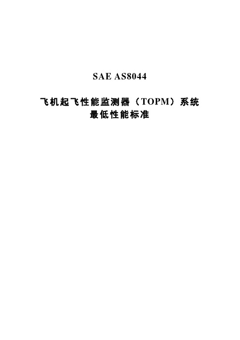
SAE AS8044飞机起飞性能监测器(TOPM)系统最低性能标准《国际自动机工程师学会(SAE )技术标准委员会章程》规定:“本报告由SAE 发布,用以促进技术与工程科学的发展水平。
使用本报告完全出于自愿,本报告对于任何特殊用途的可行性和适用性,包括由此引起的任何专利侵权问题,均由使用者个人承担责任。
”SAE 至少每五年对各技术报告审查一次,届时会重申、修订或废除这些报告。
SAE 欢迎您提出书面意见和建议。
国际自动机工程师学会2007年版权所有保留所有权利。
未经SAE 事先书面许可,不允许该出版物的任何部分被复制、存储于检索系统或被以任何形式或任何途径,包括电子、手抄、照片、录音或其他方式等传播。
订购方式: 电话: 877-606-7323(美国和加拿大境内)电话: 724-776-4970(美国境外)传真: 724-776-0790邮箱: CustomerService@SAE 网址: 航空航天 标准 AS8044发布日期: 1987-08重申日期: 2007-07飞机起飞性能监测器(TOPM )系统最低性能标准基本情况根据SAE 5年复审政策,已重申本文件。
目录章节标题 页码 1. 范围 (3)1.1范围 .................................................................................................................................. 3 1.2产品分类 .......................................................................................................................... 3 1.2.1类型 .................................................................................................................................. 3 1.2.2类别 .................................................................................................................................. 3 1.3适用范围 .......................................................................................................................... 4 1.3.1适用飞机 .......................................................................................................................... 4 1.3.2适用机场 .......................................................................................................................... 4 1.3.3 适用操作 .. (4)2. 引用文件 (4)2.1适用文件 .......................................................................................................................... 4 2.1.1SAE 出版物 ...................................................................................................................... 4 2.1.2行业规范 .......................................................................................................................... 5 2.1.3联邦航空条例 .................................................................................................................. 6 2.1.4军用规范 .......................................................................................................................... 6 2.1.5专用文件 .......................................................................................................................... 6 2.2定义 .................................................................................................................................. 6 2.3 符号和缩写词 (7)AS8044 第2页章节标题页码3. 技术要求 (7)3.1 总则 (7)3.1.1 材料和工艺 (7)3.1.2 标识 (8)3.1.3 互换性 (8)3.1.4 信息获取途径 (8)3.1.5 信息兼容 (8)3.1.6 外壳绝缘 (8)3.1.7 TOPM系统运行 (8)3.1.8 TOPM系统可靠性要求 (11)3.1.9 TOPM系统运行程序 (11)3.1.10 危害性分析 (11)3.2 性能、标准条件 (11)3.2.1 试验条件 (11)3.3 性能、环境条件 (12)3.3.1 试验条件 (12)3.3.2 性能要求 (12)3.3.3 安装—专用条件 (13)3.3.4 验证试验 (13)4. 试验或检验抽样与方法 (13)4.1 试验检验责任 (13)4.2 试验效果 (13)4.3 试样 (13)4.4 试验程序、标准试验条件 (13)4.4.1 介电试验 (13)4.4.2 密封试验 (14)4.4.3 TOPM外部干扰 (14)4.4.4 性能测定与显示 (14)4.5 试验程序—环境试验条件 (14)4.6 报告与说明 (15)4.6.1 总结报告 (15)4.6.2 试验资料/分析证明 (16)4.6.3 附录A“委员会注意事项和背景信息” (17)第3页AS80441. 范围1.1 范围:本航空航天标准(AS)确立了构成飞机起飞性能检测器(TOPM)系统的所有传感器、计算机、应答器与飞机驾驶舱控制装置/显示装置的最低性能标准。
Testo 最新一代气流速度和空气质量仪测试仪说明书

Latest generation testo air velocity & IAQ probes with fixed cableInstruction manualContents Contents1About this document (3)2Safety and disposal (3)3System description (4)4Description of the instrument (5)4.1Hot wire probe, including temperature sensor (0635 1032) (5)4.2Vane probe (Ø 16 mm) (0635 9532) (6)4.3High-precision temperature/humidity probe up to +180°C (0636 9775) 64.4Lux probe (0635 0551) (7)4.5Turbulence probe (0628 0152) (7)4.6Laboratory flue probe (0635 1052) (8)5Commissioning (9)6Maintenance (9)6.1Maintaining the probes (9)6.1.1Cleaning the instrument (9)6.1.2Calibration (9)7Technical data (10)8Accessories and spare parts (13)1 About this document1About this document•The instruction manual is an integral part of the instrument.•Please read this instruction manual through carefully and familiarize yourself with the product before putting it to use.•Pay particular attention to the safety instructions and warning advice in order to prevent injury and damage to the product.•Keep this documentation to hand so that you can refer to it when necessary.•Always use the complete original instruction manual.•Hand this instruction manual on to any subsequent users of the product.2Safety and disposalSecurity•Only use the product properly, for its intended purpose, and within the parameters specified in the technical data. Do not apply any force. •Dangers may also arise from the systems being measured or the measuring environment: always comply with the locally valid safety regulations when carrying out measurements.•Do not carry out any contact measurements on uninsulated, live parts. •Do not store the product together with solvents. Do not use any desiccants. •Only carry out maintenance and repair work on this instrument which is described in the documentation. Follow the prescribed steps exactly when doing the work. Use only original spare parts from Testo.•Temperature information given on probes/sensors relates only to the measuring range of the sensor technology. Do not expose handles and feed lines to temperatures in excess of 50°C (122°F), unless they are expressly authorized for use at higher temperatures.•Do not operate the instrument if there are signs of damage on the housing or supply lines.33 System description4Disposal• At the end of its useful life, deliver the product to the separate collectionpoint for electric and electronic devices (observe local regulations) or return the product to Testo for disposal.•WEEE Reg. no. DE 753343523 System descriptionYou have acquired a probe, if applicable with additional probe-specific accessories.The probe can be directly connected to the testo 440 measuring instrument.You will find detailed information about how each of the probes works along with the testo 440 measuring instrument in the corresponding chapter of the instruction manual for the measuring instrument.4 Description of the instrument54 Description of the instrument4.1 Hot wire probe, including temperaturesensor (0635 1032)ApplicationIn conjunction with the testo 440, the hot wire probe is suitable for flow and humidity measurements in ventilation ducts. Structure1 Sensor with protective sleeve2 Probe adapter3 Telescope with scaling 4Cable 5 Connection plugCAUTIONDamage to sensor possible! - Do not touch sensor!- Close the protective sleeve after the measurement.Low flow velocities may result in greater measurement uncertainties during temperature and humidity measurement. The probe should be switched on outside a duct under the following conditions: Ambient temperature: 20°C Flow: approx. 0 m/s.Collapse the telescope after use and do not constrict with the cable.4 Description of the instrument64.2 Vane probe (Ø 16 mm) (0635 9532)ApplicationIn conjunction with the testo 440, the vane probe (Ø 16 mm) is suitable for flow measurements in ventilation ducts. Structure1 Probe head2 Telescope3 Telescope handle4 CableCAUTIONDamage to sensor possible! - Do not touch sensor!- Put the protective sleeve on after the measurement.Collapse the telescope after use and do not constrict with the cable. 4.3 High-precision temperature/humidityprobe up to +180°C (0636 9775)ApplicationIn conjunction with the testo 440, the high-precision temperature/humidity probe is used to measure humidity and temperature. Structure1 Probe head 2Sintered cap 3 Probe shaft 4 Handle 5 CableCAUTIONDamage to sensor possible! - Do not touch sensor!4 Description of the instrument74.4 Lux probe (0635 0551)ApplicationIn conjunction with the testo 440, the lux probe is used to determine the illuminance of workplaces. In general, the illuminance measurement of warm light or white LEDs is possible because these types of LED cover the whole spectral range of the human eye. The measurement of one-colour LEDs (e.g. blue LEDs) is not recommended. Structure1 Measuring sensor2 CableCAUTIONDamage to sensor possible! - Do not touch sensor!4.5 Turbulence probe (0628 0152)ApplicationIn conjunction with the testo 440, the turbulence probe is used for temperature and air pressure measurement. Structure1 Sensor2 Guard3 Probe shaft4 Handle5 Cable4 Description of the instrument8Damage to sensor possible! - Do not touch sensor!The probe contains sensitive components. Please handle the probe with care.4.6 Laboratory flue probe (0635 1052)ApplicationIn conjunction with the testo 440, the laboratory flue probe is used to determine flow velocities in laboratory fume cupboards. Structure1 Sensor2 Protective sleeve3 Button 4Handle 5 CableATTENTIONDamage to sensor possible! - Do not touch sensor!- Push the protective sleeve over the sensor after the measurement.The probe contains sensitive components. Please handle the probe with care.Low flow velocities may result in greater measurement uncertainty during temperature measurement!5 Commissioning95 CommissioningDisplaying readings✓Sensor is connected to the measuring instrument.Readings are displayed.6 Maintenance6.1 Maintaining the probes6.1.1 Cleaning the instrumentDo not use any aggressive cleaning agents or solvents; instead use mild household cleaning agents or soapy water.Always keep the connections clean and free from grease and other deposits.Clean the instrument and the connections with a damp cloth and dry them off.6.1.2 CalibrationThe probes are supplied with a factory calibration protocol as standard. Recalibration of the probes once every 12 months is recommended in many applications. This can be carried out by Testo Industrial Services (TIS) or othercertified service providers with the aid of easy-to-use service software. Please contact Testo for further information.7 Technical data107 Technical data• Adjustment conditions for flow probes:Adjustment in free jet Ø 350 mm, reference pressure 1013 hPa, based on testo reference Laser Doppler Anemometer (LDA). • Note for flow probes:Low flow velocities may result in greater measurement uncertainties during humidity and temperature measurement! • Note for humidity probes:Please do not use the humidity probes in condensing atmospheres. For continuous use in high-humidity ranges > 80% RH at ≤ 30°C for > 12 h > 60% RH at > 30°C for > 12 hplease get in touch with Testo Service or contact us via the Testo website.Hot wire probe, including temperature sensor (0635 1032) FeatureValueMeasuring range0 to +30 m/s -20 to +70°C 700 to 1100 hPaAccuracy(at 22°C, ± 1 digit)± (0.03 m/s + 4% of m.v.) (0 to 20 m/s) ± (0.5 m/s + 5% of m.v.) (20.01 to 30 m/s) ± 0.5°C (0 to +70°C) ± 3 hPa Resolution0.01 m/s 0.1°C 0.1 hPaStorage temperature -20°C to +70°C Operating temperature -20°C to +70°C Protection class IP20DimensionsCable length: 1.7 mExtension length with telescope: 850 mm Ø probe head on the sensor: 9 mm Ø end of probe shaft: 12 mm Weight90 gDirectives, standards and testsEU Directive: 2014/30/EU7 Technical data11Vane probe (Ø 16 mm) (0635 9532) FeatureValue Measuring range0.6 to 50 m/s Accuracy(at 22°C, ± 1 digit)± (0.2 m/s +1% of m.v.) (0.6 to 40 m/s) ± (0.2 m/s +2% of m.v.) (40.1 to 50 m/s) Resolution0.1 m/s Storage temperature-10°C to +70°C Operating temperature-10°C to +70°C Protection classIP20 Dimensions Cable length: 1.7 mExtension length with telescope: 850 mmØ probe head: 16 mmØ end of probe shaft: 12 mmWeight 148 gDirectives, standards andtestsEU Directive: 2014/30/EUHigh-precision temperature/humidity probe up to +180°C (0636 9775) FeatureValue Measuring range-20 to +180°C 0 to 100% RH Accuracy(at 22°C, ± 1 digit)±0.5°C (-20 to 0°C) ±0.4°C (0.1 to +50°C) ±0.5°C (+50.1 to +180°C) Accuracy(at 25°C, ±1 digit) ±3% RH (0 to 2% RH) ±2% RH (2.1 to 98% RH)±3% RH (98.1 to 100% RH)Additional uncertainty- Long-term stability: ±1% RH / yearResolution 0.1°C0.1% RHTemperature coefficient type (k=1) ±0.03% RH/K (-20 to +50°C)type (k=1) ±0.06% RH/K (+50 to +180°C)Storage temperature -20 to 60°COperating temperature Handle: -5 to +50°CProbe head: -20 to +180°CProtection classIP207 Technical data12 FeatureValue Dimensions Cable length: 1.4 mOverall probe length: 420 mmProbe shaft length: 270 mmØ probe shaft: 12 mmWeight 255 gDirectives, standards andtestsEU Directive: 2014/30/EULux probe (0635 0551) FeatureValue Measuring range0 to 100,000 lux Accuracy(at 22°C, ±1 digit)DIN EN 13032-1 Appendix B; Class C according to DIN 5032-7 Resolution0.1 lux < 10,000 lux 1 lux ≥ 10,000 lux Storage temperature-20 to +50°C Operating temperature0 to +50°C Ambient humidityPreferred use: 20 to 80% RH DimensionsCable length: 1.4 m Housing: 110 x 55 x 22 mm Weight 110 g Directives, standards andtestsEU Directive: 2014/30/EUTurbulence probe (0628 0152)FeatureValue Measuring range 0 to +5 m/s0 to +50°C700 to 1100 hPaAccuracy (at 22°C, ± 1 digit) ± (0.03 m/s + 4% of m.v.) (0 to +5 m/s)± 0.5°C± 3 hPaResolution 0.01 m/s0.1°C0.1 hPaStorage temperature -20 to +60°COperating temperature0°C to +50°C8 Accessories and spare parts13 FeatureValue Dimensions Cable length: 1.4 mOverall probe length: 400 mmProbe shaft length: 195 mmWeight 250 gDirectives, standards andtestsEU Directive: 2014/30/EULaboratory flue probe (0635 1052) FeatureValue Measuring range 0 to +5 m/s0 to +50°C700 to 1100 hPaAccuracy (at 22°C, ± 1 digit) ± (0.02 m/s + 5% of m.v.) (0 to +5 m/s)± 0.5°C± 3 hPaResolution 0.01 m/s0.1°C 0.1 hPaStorage temperature -20 to +60°COperating temperature 0°C to +50°CDimensions Cable length: 1.4 mOverall probe length: 350 mmProbe shaft length: 195 mmWeight 230 gDirectives, standards andtestsEU Directive: 2014/30/EU8 Accessories and spare partsDescription Order no. Measuring stand with standard-compliant positioning of probes (including bag)0554 15900971 0455 en 03。
飞机航电系统故障分析方法与故障诊断技术探讨王畅

飞机航电系统故障分析方法与故障诊断技术探讨王畅发布时间:2021-10-27T02:59:04.871Z 来源:《中国科技人才》2021年第20期作者:王畅[导读] 目前,我国的经济在快速发展,社会在不断进步,现阶段民航飞机的日常地面维护工作中,绝大多数的飞机航电系统故障问题,都是经过对LRU系统的更换,或者LRM组件的更换,有效排除故障问题。
沈阳飞机工业(集团)有限公司辽宁沈阳 110000摘要:目前,我国的经济在快速发展,社会在不断进步,现阶段民航飞机的日常地面维护工作中,绝大多数的飞机航电系统故障问题,都是经过对LRU系统的更换,或者LRM组件的更换,有效排除故障问题。
相对来讲此种故障排除方法,思路较为简单,并未对地面维护人员提出较高的技能要求。
地面维护人员在对故障分析诊断过程中,只需要掌握熟悉的系统原理构造,并且经查阅有关故障系统的手册,通过航电系统的设备故障代码,就能完成系统故障分析及排除。
而飞机航电系统一旦出现故障问题,必然会对飞机的飞行安全造成影响。
同时随着科技水平不断创新,飞机航电系统组成逐步复杂化,简单的人工排查难以快速准确的定位故障。
因此,对航电系统故障诊断技术加以解决,已经成为现阶段的研究重点。
关键词:飞机航电系统;故障分析;故障诊断引言飞机航电系统故障关系到飞机的安全飞行,因此加强对航电系统故障的分析与诊断是提高飞机安全运行、提高航空事业快速发展的重要技术。
随着飞机制造技术的不断发展,飞机航电系统越来越复杂,因此掌握科学的故障分析与诊断方法是当前飞机故障检修人员需要面临的主要问题。
1飞机航电系统故障分析1.1导航/通信系统故障飞机航空系统的组件较多,系统内部集成了甚高频导航、多种类型的接收机,能够实现多种信号的处理,在完成信号处理之后能够将其各种信息传送给相应的平台,实现信息的共享和信息需求的支持,是飞机航电系统的重要组成部分。
所以,导航/通信系统故障的常见类型有COM信号收发故障、GPS卫星信号故障以及NA V收发故障。
航空装备SNS系统编码表
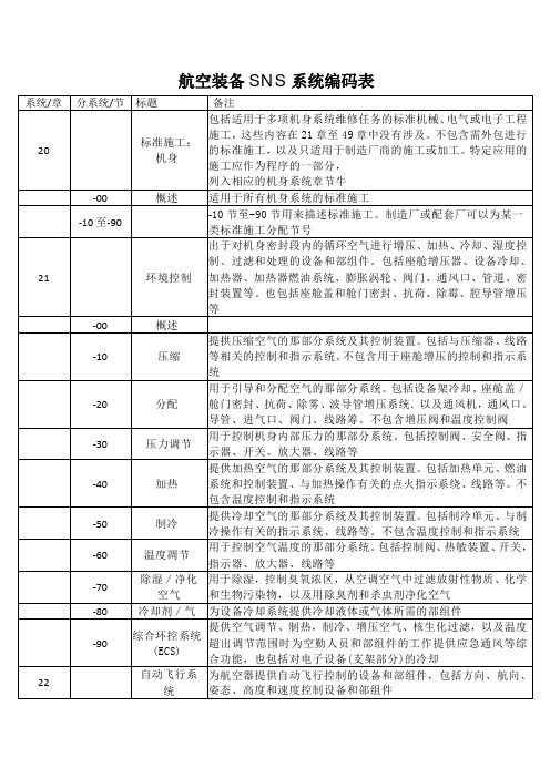
-70
-80
增升装置
28
燃油
-00
概述 用于储存燃油的那部分系统。包括油箱密封、软油箱舱、通气 系统、油泵导油装置,单元油箱之间的连通件、机翼上的加油 口和口盖等,也包括蓄油器供油增压系统和不属于分配系统的 油箱内蓄油器 用于从加油接头向储存系统分配燃油,以及从储存系统将燃油
-10
储存
-20
分配
输送到动力装置燃油快卸接头的那部分系统。包括管路、泵、 阀门、控机构等 用于在飞行时将燃油排放到机外的那部分系统。包括管路、阀 门、控制机构,放油槽等 用于指示燃油油量、温度和压力的那部分系统。包括油箱内燃 油增压压力警告系统。不包括发动机燃油流量和压力
附加舱
-60 -70 -80 26 -00 -10 -20 -30
应急设备
备注 指容纳旅客或工作人员舱室,包括不是更衣室的休息室。主要 有座椅、操纵台、设备架、卧铺、上部行李架、帘子、壁挂、 地毯、杂志架、屏风、壁挂式温度计,备用的电灯泡、保险丝 等 储存和准备饮食的区域。包括活动的和固定的橱柜,烤箱,冰 箱、垃圾箱、餐具架、咖啡机和分装器、器皿、电插座、线路 等 指包含洗手盆、梳妆台和抽水马桶的盥洗室和更衣室区域。包 括镜子,座椅,橱柜、分配装置,电插座等。有关洗手盆和抽 水马桶的内容在 38 章中 乘客和/或空勤人员使用的附加舱室。包括空勤休息舱,睡眠 舱等 在应急程序中需要使用的设备。包括撤离设备,救生艇,救生 衣,事故地点发射机,水下定位装置、急救包、恒温箱、氧气 袋,医疗担架、着陆照明弹和信号弹、减速伞、撤离信号系统 等。不包含灭火器、氧气设备或面罩 用于隔热和隔音的隔离层。包括驾驶舱、客舱以及附加的隔离 层等 探测和指示火灾或烟雾,以及储存灭火剂并将其输送到飞机所 有受保护区域的固定式和便携式设备和部组件,包括灭火瓶、 阀门、管路等 用于感知和指示过热,烟雾或火灾的那部分系统 用于灭火的固定式或便携式装置 用于感知、指示和防止火焰蔓延到燃油系统而引起爆炸的那部 分系统 用于控制飞机飞行姿态特性的设备和部组件。包括主飞行操纵 面和辅助飞行操纵面,以及增升系统的功能及维护信息,但不 包含在结构章节中说明的操纵面的结构维护信息。包括驾驶杆 手柄、方向舵脚蹬、变速箱,操纵杆及钢索,连杆、液压阀、 作动筒、控制部件、控制与显示装置、计算机、变换器,变压 器、传感器部件、显示器、陀螺仪,加速度计、伺服系统,警 告系统以及控制锁定装置等。包括旋翼飞机的旋翼操纵内容 飞机横滚操纵设备和部组件。包括驾驶盘 (杆 )、钢索、助力器, 连杆,操纵面、指示器等 飞机航向控制设备和部组件。包括方向舵脚蹬、调整片操纵轮, 钢索、助力器、连杆、操纵面、位置指示器等
I 型机载空中交通告警和防撞系统(TCAS I)机载设备
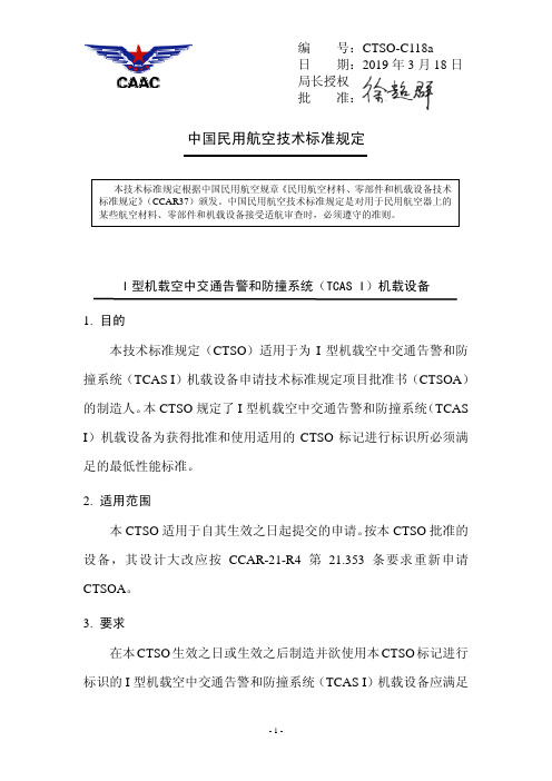
编号:CTSO-C118a局长授权批准:中国民用航空技术标准规定I型机载空中交通告警和防撞系统(TCAS I)机载设备1. 目的本技术标准规定(CTSO)适用于为I型机载空中交通告警和防撞系统(TCAS I)机载设备申请技术标准规定项目批准书(CTSOA)的制造人。
本CTSO规定了I型机载空中交通告警和防撞系统(TCAS I)机载设备为获得批准和使用适用的CTSO标记进行标识所必须满足的最低性能标准。
2. 适用范围本CTSO适用于自其生效之日起提交的申请。
按本CTSO批准的设备,其设计大改应按CCAR-21-R4第21.353条要求重新申请CTSOA。
3. 要求在本CTSO生效之日或生效之后制造并欲使用本CTSO标记进行标识的I型机载空中交通告警和防撞系统(TCAS I)机载设备应满足RTCA/DO-197A《I型主动空中交通告警和防撞系统(Active TCAS I)最低运行性能标准》(1994.9.12)第2.1节和第2.2节的要求,以及RTCA/DO-197A Change 1(1997.7.29)对第2节的修订。
a.功能本CTSO的标准适用于提供可靠交通警告和防撞功能的设备,该设备预期用于装有应答机的航空器上。
b. 失效状态类别(1)本CTSO第3.a节定义的功能失效会导致重大的失效状态。
(2)本CTSO第3.a节定义的功能丧失属微小的失效状态。
(3)设备的设计保证等级应至少与这种失效状态类别相对应。
c. 功能鉴定应按RTCA/DO-197A第2.4节中试验条件,证明设备性能满足要求。
d. 环境鉴定应按RTCA/DO-197A第2.3节中试验条件,采用该设备适用的标准环境条件和试验程序,证明设备性能满足要求。
申请人可采用除RTCA/DO-160G以外其它适用于I型机载空中交通告警和防撞系统(TCAS I)机载设备的标准环境条件和试验程序。
注:通常情况下,RTCA/DO-160D(包括Change 1和Change 2)或早期版本不再适用,如果使用该版本则需按照本CTSO第3.g节中的偏离要求进行证明。
逆向工程最新应用

美国国家航空航天局应用逆向工程测试太空时代的“宇航员救生艇”如果宇航员无论什么情况下都必须撤离国际太空站,那么,他们可能会乘坐象X-38 -NASA的机组人员往返运载器(CRV)的原型-这样的太空时代救生艇。
X-38是一种无翼飞机,它的气动升力来自机身的形状,而不是机翼。
CRV专门设计用来把七名宇航员从轨道送到离地面大约四万英尺的地方,在这里,可控的转向降落伞将展开,并把飞机带到它的着陆地点。
在脱离轨道和转向降落伞展开期间,电子机械式调节器鼓起X-38的飞行控制面,以调整它的飞行路线。
美国国家航空航天局NASA工程师面临的一个问题是如何测试调节器,它必须能够在一个不断快速变化的环境中,承受35倍的地球引力、重返大气层的热量和压力、以及超音速大气飞行紊乱所带来的影响。
高速背载为了解决这个问题,位于美国加利福尼亚州爱德华兹市的NASA Dryden飞机研究中心的工程师通过研究认为,把调节器安装在F-15 鹰式飞机上,这种飞机的高度灵敏性和高达每小时1,600多英里的速度,能够支撑X-38必须承受的各种压力。
这种方法的困难之一是,把调节器安装在F-15上,并使它们成为一个整体。
X-38的方向舵调节器是通过把它安装在位于F-15驾驶舱和垂直稳定翼之间的气动整流罩内来测试的,垂直稳定翼控制着F-15的减速板。
在飞行员的控制下,减速板伸到气流中,气动负载被X-38的调节器顶起。
F-15的上表面具有复杂的几何图形,比如,多个方向的复合曲线,所以,设计一个可以刚好安装在机身上的整流罩,是一项既辛苦又耗时的工作。
开始使用Pharaoh方法但是,一种被称为Pharaoh的逆向工程工具能让NASA工程师使用一种便携式坐标测量机(CMM, Coordinate Measuring Machine),把F-15的几何图形直接数字化到Pro/ENGINEER中。
Pharaoh是美国加利福尼亚州拉霍亚市HighRES有限公司的产品。
军用发动机之欧阳美创编

罗尔斯·罗伊斯公司『RR』 TF41 系列TF41牌号TF41用途军用涡扇发动机类型涡轮风扇发动机国家美国厂商罗尔斯·罗伊斯公司/艾利逊发动机公司生产现状停产装机对象单发攻击机A-7D(空军型)、A-7E(海军型)、A-7H及其教练型TA-7H研制情况TF41是美国艾利逊公司和英国罗尔斯·罗伊斯公司联合研制和生产的涡轮风扇发动机。
该发动机是英国罗尔斯·罗伊斯公司斯贝RB168-25的一种改型,用来装A-7攻击机。
1966年美空军与这两家公司签订合同,艾利逊公司负责研制和生产TF41发动机特有的零部件,罗尔斯·罗伊斯公司提供技术合作和与斯贝发动机通用的零部件。
TF41-A-1发动机于1967年10月首次试车,1968年6月通过试飞前规定试验。
1969年6月正式完成定型试验。
在研制过程中,发动机积累了3600h以上的试验。
经过多年的修改设计,使发动机翻修寿命达到1500h。
主要改型有TF41-A-1、TF41-A-2和TF41-A-100/-A-400。
结构和系统(TF41-A-1)进气口整体钢机匣。
无进口导流叶片。
风扇及外涵3级轴流式。
水平对开机匣。
全外涵。
低压压气机2级轴流式,与风扇同轴。
高压压气机11级轴流式。
燃烧室环管形。
有10个火焰筒和10个双油路喷嘴。
高压涡轮2级轴流式。
2级导向器叶片和第1级转子叶片气冷。
低压涡轮2级轴流式。
尾喷管内、外涵气流经简单混合在喷管排气段内混合后排出。
控制系统机械液压式。
转速和加速自动控制,应急时人工超控。
技术数据(TF41-A-2)起飞推力(daN) 6679最大起飞耗油率[kg/(daN·h)] 0.66推重比 4.97空气流量(kg/s) 119.3涵道比 0.74总增压比 21.4涡轮进口温度(℃) 1155直径(mm) 1004长度(mm) 2900质量(kg) 1370RTM322RTM322系发动机结构牌号RTM322用途军用涡轴发动机类型涡轮轴发动机国家法国厂商罗尔斯·罗伊斯公司/透博梅卡生产现状研制完毕,准备投入批生产装机对象RTM322-01 EH-101、AS322/AS.532、NH90、AH-64A、S-70C、UH-60A/B、SH-60B、WS-30、A129、卡-62R。
NAMUR接口1 4英寸和1 2英寸高流气动阀G1 4英寸和G1 2英寸用于控制空气驱动器应用说明书

aerospace climate control electromechanical filtrationfluid & gas handling hydraulics pneumatics process control sealing & shieldingD2D1"2""4"MFTD4D3Ra 3.2Description of ApplicationsControl of single or double acting pneumatic actuators, in safe or dangerous areas.NAMUR Interfaces 1/4" & 1/2"Th e interface design is conform to the NAMURstandard and to the VDI/VDE 3845 recommendations of the actuator industry. It allows a compact design of the actuator/valve unit. In case of a 3/2 function,the air of the actuator spring chamber also fl owsthrough the pilot valve (re-breather function).Th is prevents corrosion of the actuator springs.Market DescriptionProcess industriesChemical, Petrochemical industries Oil & GasWater & Sewage Pulp & Paper Food & BeveragePharmaceutical industryPowder Dosing-Transportation Air DryersF T D1 D2 D3 D4 min. M mm mm mm Mm mm M5 1/4 32 24 8 12 M5 M6 1/2 45 40 10 16 M6F: 2 mounting holes - T: 2 actuators control port - M: 2 holes for dowel pins● High fl ow: 1.250 l/min (1/4"), 3.000 l/min (1/2")● Compact design ● Long life expectancy● N3x series compatible with any Parker Lucifer coil(ATEX or not) of electrical group 2 (8/9 W coils)● Fail safe standard● Reduced inventory (3/2 & 5/2 functions with the samevalve on 341Nx5 series)● Mechanical part of the valve ATEX certifi ed accordingstandard EN 13463-1 & -5Function: 3/2 , 5/2, 3/2 <=> 5/2 and 5/3 valves.Manual override: Standard on all versions.Design: Solenoid operated spool valve with combined spring and air return & external air pressure operated versions.Mounting:For direct mounting on NAMUR interface ¼" & ½".Mounting position: I ndifferent.Material specifi cations: Aluminium body. Internal parts from stainless steel.Sealing material from NBR.Range of admissible pressure drop: Δp min. = see table. Δp max. = 10 bar.Media:Dry or lubricated air.Fluid temperature: Min. 0°C Max. + 50°C Ambient temperature: -10°C to +50°CElectrical part: N0x series are compatible with 22mm coil 496131 / 496482 / 496637 SeriesN3x series are compatible with 32/37/40 mm coils part of electrical group 2 (8/9W), including 481865 / 495870 / 495905 Series.Solenoid duty: 100% ED.Voltage: 481865 coil: 12 VDC , 24 VDC , 48 VDC , 110VDC, 24 V / 50 AC, 48 V / 50 AC,110 V / 50 AC, 220-230V/50 AC, 115 V / 60 Hz AC, 230 V / 60 AC.Voltage tolerance: ± 10% of nominal for 481865 coil.Class of insulation material: Class F for 481865 coil.Standards:Mechanical ATEX conform to EN 13463-1 & -5.Customer Value PropositionGeneral Information1313135135135135135G1/4" SeriesSolenoid Operated VersionsN03-N05 Series with 22 mm Coil3/2 Solenoid operated - Combined spring & air return (monostable)1/4 7 1250 2.5 10 10 50 NBR 331N03 - 496131 3 3 300 11/4 7 1250 2.5 10 10 50 NBR 331N03 - 496482 3 3 300 11/4 7 1250 2.5 10 10 50 NBR 331N03 - 496637 3 3 30015/2 Solenoid operated - Combined spring & air return (monostable)1/4 7 1250 2.5 10 10 50NBR 341N03 - 496131 3 3 300 21/4 7 1250 2.5 10 10 50 NBR 341N03 - 496482 3 3 300 2 1/47 1250 2.5 10 1050NBR 341N03 - 496637 3 3 30023/2 <=> 5/2 with conversion plate - Solenoid operated Combined spring & air return (monostable)1/4 7 1250 2.5 10 10 50NBR 341N05 - 496131 3 3 310 3 1/4 7 1250 2.5 10 10 50 NBR 341N05 - 496482 3 3 310 3 1/47 1250 2.5 10 1050NBR 341N05 - 496637 3 3 31035/2 Solenoid operated and return (bistable)1/47 1250 2.5 10 10 50NBR 347N03 - 496131 3 3 430 41/4 7 1250 2.5 10 10 50 NBR 347N03 - 496482 3 3 430 4 1/47 1250 2.5 10 1050NBR 347N03 - 496637 3 3 43045/3 W1 closed in center position - Solenoid operated and return1/4 7 1250 2.5 10 10 50NBR 342N03 - 496131 3 3 430 41/4 7 1250 2.5 10 10 50 NBR 342N03 - 496482 3 3 430 4 1/47 1250 2.5 10 1050NBR 342N03 - 496637 3 3 43045/3 W3 exhausted in center position Solenoid operated and return (bistable)1/4 7 1250 2.5 10 10 50NBR 343N03 - 496131 3 3 430 41/4 7 1250 2.5 10 10 50 NBR 343N03 - 496482 3 3 430 4 1/47 1250 2.5 10 1050NBR 343N03 - 496637 3 3 4304Please consult the "How to Order" part at the end of each coil chapter.Dimensions Reference 3Dimensions Reference 4404040403232322222222232326767676767505050505013 13 13 13 13 13 13 13 44 44 44 222236.536.5G1/4" (2x)G1/4" (3x)G1/4" (3x)G1/4" (3x)M5M5M5M52323232336,52424242423232323868610290 121414101212344355513332227.27.27.27.2Dimensions Reference 1Dimensions Reference 2131351351352440403232879738381313 19.519.513132222 24243232DIN 43650ADIN 43650A G1/8"G1/8"2222 1001302323232324 24 14 12245533G1/4" (3x)G1/4" (3x)M5M52222327.27.5Solenoid Operated VersionsN33-N35 Series with 32 / 37 / 40 mm CoilAdmissible Max. admissible differential fl uidPort size Orifi ce Q N pressure temperatureSeat Reference Consumption Weight Elect. Dim. (bar) (ºC)disc number Power (g) Group Ref.(Watt) max. Min. = 0ºC G mm L/min min DC= AC~ Air & Valve Housing Coil DC AC Neutral gases3/2 <=> 5/2 with conversion plate - Solenoid operated Combined spring & air return (monostable)1/4 7 1250 2.5 10 10 50NBR 341N35 2995 481865 9 8 480 2 5 1/4 7 1250 2.5 10 10 50 NBR - 2995 495870 9 8 700 - 2 1/47 1250 2.5 10 1050NBR - - 495905 8 8 740 - 25/2 Solenoid operated and return (bistable)1/47 1250 2.5 10 10 50NBR 347N33 2995 481865 9 8 750 2 6 1/4 7 1250 2.5 10 10 50 NBR - 2995 495870 9 8 1190 2 - 1/47 1250 2.5 10 1050NBR - - 495905 8 8 1270 2 -5/3 W1 closed in center positionSolenoid operated and return (bistable)1/4 7 1250 2.5 10 10 50NBR 342N33 2995 481865 9 8 750 2 6 1/4 7 1250 2.5 10 10 50 NBR - 2995 495870 9 8 1190 2 - 1/47 1250 2.5 10 1050NBR - - 495905 8 8 1270 2 -Please consult the "How to Order" part at the end of each coil chapter.Dimensions Reference 5Dimensions Reference 61313513513540404032323213 13 13 13131344 22 22 22 22 86868623232323232324 24 24 355133G1/4" (2x)G1/4" (3x)G1/4" (3x)G1/8G1/8G1/8M5M5M52222227.27.27.2External Pressure Air Operated Series 5xx N03 SeriesAdmissible Max. admissible differential fl uidPort size Orifi ce Q N pressure temperatureSeat Reference Consumption Weight Dimensions (bar) (ºC)disc number Power (g) Reference(Watt) max. Min. = 0ºC G mm L/min min DC= AC~ Air & Valve Housing Coil DC AC Neutral gases3/2 External pressure air operatedCombined spring & air return (monostable)External pressure supply 2.5 to 10 bar1/4 7 1250 2.5 10 10 50 NBR 531N03 - w/o - - 21075/2 external pressure air operatedCombined spring & air return (monostable)External pressure supply 2.5 to 10 bar1/47 1250 2.5 10 1050NBR 541N03 - w/o - - 21085/2 external pressure air operatedExternal pressure air return (bistable)External pressure supply 2.5 to 10 bar1/47 1250 2.5 10 1050NBR 547N03 - w/o - - 24095/3 W1 closed in center position - External pressure air operatedExternal pressure air return (bistable)External pressure supply 2.5 to 10 bar1/47 1250 2.5 10 1050NBR 542N03 - w/o - - 2409Dimensions Reference 7Dimensions Reference 8Dimensions Reference 913135135Solenoid Operated VersionsN34 Series with 32 / 37 / 40 mm CoilAdmissible Max. admissible differential fl uidPort size Orifi ce Q N pressure temperatureSeat Reference Consumption Weight Elect. Dim. (bar) (ºC)disc number Power (g) Group Ref.(Watt) max. Min. = 0ºC G mm L/min min DC= AC~ Air & Valve Housing Coil DC AC Neutral gases3/2 Solenoid operatedCombined spring & air return (monostable)1/2 12 3000 2.5 10 10 50NBR 331N34 2995 481865 9 8 910 2 10 1/2 12 3000 2.5 10 10 50 NBR - 2995 495870 9 8 1130 2 - 1/212 3000 2.5 10 1050NBR - - 495905 8 8 1170 2 -5/2 Solenoid operatedCombined spring & air return (monostable)1/2 12 3000 2.5 10 10 50NBR 341N34 2995 481865 9 8 900 2 11 1/2 12 3000 2.5 10 10 50 NBR - 2995 495870 9 8 1120 2 - 1/212 3000 2.5 10 1050NBR - - 495905 8 8 1160 2 -5/2 Solenoid operated and return (bistable)1/212 3000 2.5 10 10 50NBR 347N34 2995 481865 9 8 1240 2 12 1/2 12 3000 2.5 10 10 50 NBR - 2995 495870 9 8 1680 2 - 1/212 3000 2.5 10 1050NBR - - 495905 8 8 1760 2 -Please consult the "How to Order" part at the end of each coil chapter.Dimensions Reference 10Dimensions Reference 11Dimensions Reference 1213135External Pressure Air Operated Series5 xx N04 SeriesAdmissible Max. admissibledifferential fl uidPortsize Orifi ce QNpressure temperatureSeat ReferenceConsumptionWeightDimensions(bar)(ºC)disc number Power (g)Reference(Watt)max. Min. = 0ºCG mm L/min min DC= AC~ Air & Valve Housing Coil DC ACNeutralgases3/2 External pressure air operatedCombined spring & air return (monostable)External pressure supply 2.5 to 10 bar1/2 1230002.510 10 50 NBR531N04 - w/o - - 620 135/2 external pressure air operatedCombined spring & air return (monostable)External pressure supply 2.5 to 10 bar1/2 12 3000 2.5 10 10 50 NBR541N04 - w/o - - 600 14 Dimensions Reference 13Dimensions Reference 14● Power: 3W● Insulation Class: F (155°C)● Degree of Protection: IP65 (with plug)● Duty Cycle: 100% ED ●Ambient Temperature:-10°C to 50°C3 different types are available:● Ref. 496131for a safe area without plug ● Ref. 496482for a safe area with plug ● Ref. 496637for an ATEX area Zone 22Coils and Spare Parts Informations 496637 coil series with connection 2P + G when mounted together with the supplied Pg9 plug (delivered with the coil) are suitable for use in dangerous areas (dust Zone 22) according to the European directive ATEX 94/9/C. Protection mode: Ex tD A22 IP65 - T95°CAvailable Safe area Safe area ATEX Voltageswithout DIN plug with DIN plug Zone 22 EX II 3DOrder Order Order Code Code Code12VDC 496131 C1 496482 C1 496637 C124VDC 496131 C2 496482 C2 496637 C2 48VDC 496131 C4 496482 C4 496637 C4 110VDC 496131 C5 496482 C5 496637 C5 24/50-60VAC 496131 P0 496482 P0 496637 P0 48/50-60VAC 496131 S4 496482 S4 496637 S4 110/50-60VAC 496131 P2 496482 P2 496637 P2 115/60VAC 496131 K8 496482 K8 496637 K8230/50-60VAC 496131 P9496482 P9496637 P9How to OrderThe housing kit is already included into the coil reference, so it’s not needed to add it in the order code:Valve Reference Number - Coil Reference - Voltage code = Order codeExample: 341N03 - 496131 C2Valves and coils may be ordered also separately.Coils 22 mm for N03-N05 SeriesSafe Area & ATEX Zone 22 Ref. 496131 / 496482 / 496637Th ese coils with connection for 2 P+G DIN 43650 B plug are encapsulated in synthetic material, conform to the IEC/CENELEC safety standards and comply with European low voltage directive73/23/EC .S a f e A r e a & A T E X Z o n e 22● Power: 8W (AC) 9W (DC)● Insulation Class: F (155°C)● Degree of Protection: IP65 (with plug)● Duty Cycle: 100% ED● Voltage Tolerance -10%/+10%● Ambient Temperature -40°C/+50°C◗ The application can be limited alsoby the temperature range of the valveAvailable Order Voltages Code 12VDC 481865 C1 24VDC 481865 C2 48VDC 481865 C4 110VDC 481865 C5 24/50VAC 481865 A2 48/50VAC 481865 A4 110/50VAC 481865 A5 220-230/50VAC 481865 3D 380/50VAC 481865 A9 24/60VAC 481865 B2 115/60VAC 481865 K8 230/60VAC481865 J3How to OrderThis coil must be used together with a housing kit which includes a nut, a plate, and a washer. Housing Kit Order Code: 2995Valve Reference Number - Housing Reference - Coil Reference - Voltage Code = Order CodeExample: 341N35 - 2995 - 481865 C2Coils 32 mm / 37 mm / 40 mm for N33-N34-N35 Series Safe Area Ref. 481865N3x series are compatible with any Parker Lucifer coil part of electrical group 2. Th at group includes many diff erent coils for safe areas or areas submitted to ATEX certifi cations. Th ese coils are of the 8/9W class. Th ese coils with connection for 2P+G DIN 43650 A plug are encapsulated in synthetic material, conform to the IEC/CENELEC safety standards and comply with European low voltage directive 73/23/EC.S a f e A r e adtCoils and Spare Parts Informations ●Power: 8W● Insulation Class: F (155°C)● Degree of Protection: IP67 (with 4538 housing)● Duty Cycle: 100%●Voltage Tolerance -10%/+10%● Ambient Temperature -40°C/+50°C ◗ The application can be limited alsoby the temperature range of the valveHow to OrderValve Reference Number - Housing Reference - Coil Reference - Voltage Code = Order CodeExample: 331N34 - 4538 - 481000C2Housing 4538This enclosure is dust and water proof. It corresponds to the protection degree IP67 according to IEC/EN60529. Corrosion resistant, the metallic housing offers good protection for the coil against shocks. It can be 360° orientable. This housing must be equipped with 481000 series coil.Material: galvanized passivated steel - Degree of protection IP67 according to IEC/EN 60529 - Electrical connection: cable connection by cable gland according to DIN46320. Cable with outer diameter 6.5-13.5 mm (M20x1.5) can be simply sealed using a rubber gland resilient sealing rings. The enclosure is internally and externally fi tted with grounding and earthing screw terminals.Coils 32 mm / 37 mm / 40 mm for N33-N34-N35 Series Safe Area Coil 481000 Series with 4538 Watertight and dust proof housing IP67 Ref. 481000Coil 481000 series is encapsulated in synthetic material. Electrical connection is made with screw terminals for wire up to 1.5 mm. Th is coil conforms to the IEC/CENELEC safety standards and complies with European low voltage directive 73/23/EC. It must be used with a metallic housing.S a f e A r e a●II 3 G - Ex nAC IIC T3 / T4● II 3 D - Ex tD A22 IP65 - T 195°C / T 130°C● Power: 8W (AC) 9W (DC)● Insulation Class: F (155°C)● Degree of Protection: IP65 (with plug)● Duty Cycle: 100% ED● Voltage Tolerance -10%/+10%●Ambient temperature◗ T3 (gaz) T 195°C (dust) -40°C/+65°C ◗ T4 (gaz) T 130°C (dust) -40°C/+50°C◗ The application can be limited alsoby the temperature range of the valveAvailable Order Voltages Code 24VDC 495870 C2 48VDC 495870 C4 110VDC 495870 C5 24/50VAC 495870 A2 48/50VAC 495870 A4 110/50VAC 495870 A5 220-230/50VAC495870 3DA T E X Z o n e 2-22How to OrderThis coil must be used together with a housing kit which includes a nut, a plate, and a washer. Housing kit order code: 2995Valve Reference Number - Coil Reference - Voltage code = Order codeExample: 331N34 - 2995 - 495870 A5Coils 32 mm / 37 mm / 40 mm for N33-N34-N35 Series ATEX Zone 2-22 Ref. 495870Th is coil with connection 2P+G - when mounted together with the supplied Pg 9 plug (delivered with the coil), is suitable for use in Gas and Dust dangerous areas (Zone 2-22), according to the European directive ATEX 94/9/C . Certifi cate LCIE 05 ATEX 6003 X - Protection mode: non sparking / limited energy solenoid0081II 3 G-DA T E X z o n e 1-21●II 2 G - Ex d mb IIC T4● II 2 D - Ex tD A21 IP67 - T 130°C● Insulation Class H (180°C)● Power: 8W (AC-DC)● Degree of Protection IP67● Duty Cycle 100%● Voltage Tolerance -10%/+10%● Ambient Temperature: -40°C/+65°C◗ The application can be limited alsoby the temperature range of the valveAvailable Order Voltages Code 24VDC 495905 C2 48VDC 495905 C4 110VDC 495905 C5 24/50VAC 495905 A2 48/50VAC 495905 A4 110/50VAC 495905 E5 220-230/50VAC 495905 3D115/60 495905 E5240/60 495905 B8Electric connection is done in the connection box on an easily accessible connector terminals.M20x1.5 Cable glandHow to OrderThe housing kit is already included into the coil reference, so it’s not needed to add it in the order code:Valve Reference Number - Coil Reference - Voltage code = Order codeExample: 347N33 - 495905 C2Coils 32 mm / 37 mm / 40 mm for N33-N34-N35 Series ATEX Zone 1-21 Ref. 495905Th is coil is suitable for use in Gas and Dust dangerous areas (Zone 1-21), according to the European directive ATEX 94/9/C . It’s also IECEx certifi ed according to the IECEx Scheme. Certifi cate LCIE 02 ATEX 6451 X - Protection modes: Explosionproof solenoids with fl ameproof enclosure / encapsulation "d mb"0081II 2 G/Dnct c io o n n bo ox al a l s.s .Available OrderOrder Voltages Code Code 6VDC 483371 C0 - 12VDC 483371 C1 - 24VDC 483371 C2 494040 C236VDC 483371 C3 - 48VDC 483371 C4 - 60VDC 483371 M3 - 110VDC 483371 C5 - 125VDC 483371 3N 494040 3N 220VDC 483371 C7 494040 C712/50VAC 483371 A1 - 24/50VAC 483371 A2 494040 A248/50VAC 483371 A4 - 110-115/50VAC 483371 OA 494040 OA 220-230/50 483371 3D 494040 3D24/60VAC 483371 B2 - 110-115/60VAC 483371 6J - 220-240/60VAC 483371 4K-380/50-440/60VAC -494040 5PHow to OrderThe housing kit is already included into the coil reference, so it’s not needed to add it in the order code:Valve Reference Number - Coil Reference - Voltage code = Order codeExample: 347N33 - 483371C2Coils 32 mm / 37 mm / 40 mm for N33-N34-N35 Series ATEX Solutions Zone 1-21 Ref. 483371 & 494040Th ese coils are suitable for use in Gas and Dust dangerous areas (Zone 1-21), according to the European directive ATEX 94/9/C. Protection mode:encapsulated electrical parts with increased safety.483371…DC: 24V / 400mA - 48V / 250mA 110V / 100mAAC: 24V / 630mA - 48V / 315mA 110/115V / 160mA 220/230V / 80mA494040…DC: 24V / 400mA - 125V / 80mA48V /220V - 63mAAC: 24V / 630mA - 48V / 315mA 110/115V / 160mA220/230V / 80mAA T E X Z o n e 1-21Reference 483371 or HZ06 494040 or HZ23Approval LCIE 02 ATEX 6011 X LCIE 02 ATEX 6013 X Type of Gas II 2 G - Ex e mb II T4 II 2 G - Ex e mb II T3 II 2 G - Ex e mb II T4 protection Dust II 2 D - Ex tD A21 T 130°C II 2 D - Ex tD A21 T 195°C II 2 D - Ex tD A21 T 130°C Degree of protection I P67 I P67 Ambiant temperature -40°C to +65°C -40°C to +90°C -40°C to +65°CThe application is limited also by the temperature range of the valveClass of insulation F (155°) H (180°) Electrical connection By special cable gland or M20x1.5 "Ex e" on screw terminals for wires up to 1.5 mm². Cables with outside diameter 6.5 mm to 13.5 mm can be simply sealed using the rubber gland with resilient sealing rings supplied. Elect. DC Pn (hot) 8 W 8 W Power P (cold) 20°C 9 W 9 W AC Pn (holding) 8 W 8 W 32 VA (9 W) 32 VA (9 W) Voltage tolerance Tolerance -10/ +10% of the nominal voltageSolenoid duty Continuous duty solenoid (ED 100%)Fuses: Both electrical 483371… and 494040… parts have to be connected in series with asafety fuse according to CEI 60127-3.Spare Parts Mounting Kit and AccessoriesExhaust Flow RegulatorsMaterial Body: Brass Filter element: Sintered bronze Spring: Stainless Steel Seal: NBRG1/8" Order code: 496551 G1/4" Order code: 496552 G1/2" Order code: 496553Kit for G1/4" Modelswithout conversion plate (N x 3 Series)Kit includes the 2 mounting screws M5 x 25 A2, the dowel pin M5 x 10 A2, the 2 O-rings NBR 15 x 2.5Order code: 496132Kit for G1/2" Models (N x 4 Series)Kit includes the 2 mounting screws M6 x 35 A2, the dowel pin M6 x 12 A2, the 2 O-rings NBR 24 x 3Order code: 496133Kit for G1/4" Modelswith conversion plate (N x 5 Series)Kit includes the 2 mounting screws M5 x 35 A2, the dowel pin M5 x 20 A2,the conversion plate equipped with its seals Order code:496742Connector for 32 mm CoilConnector DIN43650 AA Pg9 2P+E Order code: 486586Housing for 22 mm CoilPlastic nut with O-ring Order code: 3125Connector for 22 mm CoilConnector DIN43650 AB Pg9 2P+E Order code:481043NotesAEROSPACEKey Markets• Aircraft engines• Business & general aviation• Commercial transports• Land-based weapons systems• Military aircraft• Missiles & launch vehicles• Regional transports• Unmanned aerial vehiclesKey ProductsFlight control systems& compon ntsFluid conveyance systemsFluid metering delivery& atomization devicesFuel systems & componentsHydraulic systems & componentsInert nitrogen generating systemsPneumatic systems & components• Wheels & brakesCLIMATE CONTROLKey MarketsAgricultureAir conditioningFood, beverage & dairy• Life sciences & medicalPrecision coolingProcessingTransportationKey ProductsCO2 controlsElectronic controllersFilter driersHand shut-off valvesHose & fi ttingsPressure regulating valvesRefrigerant distributorsSafety relief valvesSolenoid valvesThermostatic expansion valvesFILTRATIONKey MarketsFood & beverageIndustrial machineryLife sciencesMarineMobile equipmentOil & gasPower generationProcessTransportationKey ProductsAnalytical gas generatorsCompressed air & gas fi ltersCondition monitoringEngine air, fuel & oil fi ltration& syst msHydraulic, lubrication& coolant fi ltersProcess, chemical, water& microfi ltration fi ltersNitrogen, hydrogen & zeroair g n ratorsELECTROMECHANICALKey MarketsAerospaceFactory automationFood & beverageLife science & medicalMachine tools• Packaging machinery• Paper machinery• Plastics machinery & converting• Primary metalsSemiconductor & electronics• TextileWire & cableKey Products• AC/DC drives & systemsElectric actuatorsGearheadsHuman machine interfacesIndustrial PCs• InvertersLinear motors, slides and stagesPrecision stages• Stepper motorsServo motors, drives & controlsStructural extrusionsPNEUMATICSKey Markets• Aerospace• Conveyor & material handling• Factory automation• Food & beverage• Life science & medical• Machine tools• Packaging machinery• Transportation & automotiveKey ProductsAir preparationCompact cylindersField bus valve systemsGrippersGuided cylindersManifoldsMiniature fl uidicsPneumatic accessoriesPneumatic actuators & grippersPneumatic valves and controlsRodless cylindersRotary actuatorsTie rod cylindersVacuum generators, cups & sensorsFLUID & GAS HANDLINGKey MarketsAerospaceAgricultureBulk chemical handlingConstruction machineryFood & beverageFuel & gas deliveryIndustrial machineryMobileOil & gasTransportationWeldingKey ProductsBrass fi ttings & valvesDiagnostic equipmentFluid conveyance systemsIndustrial hosePTFE & PFA hose, tubing& plastic fi ttingsRubber & thermoplastic hose& couplingsTube fi ttings & adaptersQuick disconnectsHYDRAULICSKey Markets• Aerospace• Aerial lift• Agriculture• Construction machinery• Forestry• Industrial machinery• Mining• Oil & gas• Power generation & energy• Truck hydraulicsKey Products• Diagnostic equipment• Hydraulic cylinders& accumulators• Hydraulic motors & pumps• Hydraulic systems• Hydraulic valves & controls• Power take-offs• Rubber & thermoplastic hose& couplings• Tube fi ttings & adapters• Quick disconnectsPROCESS CONTROLKey MarketsChemical & refi ningFood, beverage & dairyMedical & dentalMicroelectronicsOil & gasPower generationKey ProductsAnalytical sample conditioningproducts & systemsFluoropolymer chemical deliveryfi ttings, valves & pumpsHigh purity gas delivery fi ttings,valves & regulatorsInstrumentation fi ttings, valves& r gulatorsMedium pressure fi ttings & valvesProcess control manifoldsSEALING & SHIELDINGKey MarketsAerospaceChemical processingConsumerEnergy, oil & gasFluid powerGeneral industrialInformation technologyLife sciencesMilitarySemiconductorTelecommunicationsTransportationKey ProductsDynamic sealsElastomeric o-ringsEMI shieldingExtruded & precision-cut,fabricated elastomeric sealsHomogeneous & insertedlastom ric shap sHigh temperature metal sealsMetal & plastic retainedcomposit s alsThermal management Parker’s Motion & Control TechnologiesAt Parker, we’re guidedby a relentless drive to helpour customers become moreproductive and achievehigher levels of profi tabilityby engineering the bestsystems for their require-ments. It means looking atcustomer applications frommany angles to fi nd newways to create value.Whatever the motion andcontrol technology need,Parker has the experience,breadth of product and globalreach to consistently deliver.No company knows moreabout motion and controltechnology than Parker.For further info call00800 27 27 5374.AE – UAE, Dubai Tel: +971 4 8127100********************AR – Argentina, Buenos Aires Tel: +54 3327 44 4129AT – Austria, Wiener Neustadt Tel: +43 (0)2622 23501-0*************************AT – Eastern Europe, Wiener NeustadtTel: +43 (0)2622 23501 900****************************AU – Australia, Castle Hill Tel: +61 (0)2-9634 7777AZ – Azerbaijan, Baku Tel: +994 50 2233 458****************************BE/LU – Belgium, Nivelles Tel: +32 (0)67 280 900*************************BR – Brazil, Cachoeirinha RS Tel: +55 51 3470 9144BY – Belarus, Minsk Tel: +375 17 209 9399*************************CA – Canada, Milton, Ontario Tel: +1 905 693 3000CH – Switzerland, Etoy Tel: +41 (0)21 821 87 00*****************************CL – Chile, Santiago Tel: +56 2 623 1216CN – China, Shanghai Tel: +86 21 2899 5000CZ – Czech Republic, Klecany Tel: +420 284 083 111*******************************DE – Germany, Kaarst Tel: +49 (0)2131 4016 0*************************DK – Denmark, Ballerup Tel: +45 43 56 04 00*************************ES – Spain, Madrid Tel: +34 902 330 001***********************FI – Finland, Vantaa Tel: +358 (0)20 753 2500parker.fi ****************FR – France, Contamine s/ArveTel: +33 (0)4 50 25 80 25************************GR – Greece, Athens Tel: +30 210 933 6450************************HK – Hong Kong Tel: +852 2428 8008HU – Hungary, Budapest Tel: +36 1 220 4155*************************IE – Ireland, Dublin Tel: +353 (0)1 466 6370*************************IN – India, MumbaiTel: +91 22 6513 7081-85IT – Italy, Corsico (MI)Tel: +39 02 45 19 21***********************JP – Japan, Tokyo Tel: +81 (0)3 6408 3901KR – South Korea, Seoul Tel: +82 2 559 0400KZ – Kazakhstan, Almaty Tel: +7 7272 505 800****************************LV – Latvia, Riga Tel: +371 6 745 2601************************MX – Mexico, Apodaca Tel: +52 81 8156 6000MY – Malaysia, Shah Alam Tel: +60 3 7849 0800NL – The Netherlands, OldenzaalTel: +31 (0)541 585 000********************NO – Norway, Ski Tel: +47 64 91 10 00************************NZ – New Zealand, Mt Wellington Tel: +64 9 574 1744PL – Poland, Warsaw Tel: +48 (0)22 573 24 00************************PT – Portugal, Leca da Palmeira Tel: +351 22 999 7360**************************RO – Romania, Bucharest Tel: +40 21 252 1382*************************RU – Russia, Moscow Tel: +7 495 645-2156************************SE – Sweden, Spånga Tel: +46 (0)8 59 79 50 00************************SG – Singapore Tel: +65 6887 6300SK – Slovakia, Banská Bystrica Tel: +421 484 162 252**************************SL – Slovenia, Novo Mesto Tel: +386 7 337 6650**************************TH – Thailand, Bangkok Tel: +662 717 8140TR – Turkey, Istanbul Tel: +90 216 4997081************************TW – Taiwan, Taipei Tel: +886 2 2298 8987UA – Ukraine, Kiev Tel +380 44 494 2731*************************UK – United Kingdom, WarwickTel: +44 (0)1926 317 878********************US – USA, Cleveland Tel: +1 216 896 3000VE – Venezuela, Caracas Tel: +58 212 238 5422ZA – South Africa,Kempton ParkTel: +27 (0)11 961 0700*****************************Parker WorldwideEuropean Product Information Centre Free phone: 00 800 27 27 5374(from AT, BE, CH, CZ, DE, EE, ES, FI, FR, IE, IL, IS, IT, LU, MT, NL, NO, PT, SE, SK, UK)E d . 2010-06-08Parker Hannifi n Ltd. Tachbrook Park DriveTachbrook Park, Warwick CV34 6TU United KingdomTel.: +44 (0) 1926 317 878Catalogue 1101/UK - 06/2010 - TMCZ© 2010 Parker Hannifi n Corporation.All rights reserved.。
法国航空直齿花键标准-概述说明以及解释

法国航空直齿花键标准-概述说明以及解释1.引言法国航空直齿花键标准是指法国航空工业领域对直齿花键设计和制造的规范和标准。
直齿花键作为一种重要的传动元件,在航空领域中起着至关重要的作用。
本文旨在对法国航空直齿花键标准进行全面介绍,包括其概述、设计特点以及在航空领域的应用。
通过深入了解这一标准,可以更好地促进直齿花键技术的发展,提高航空设备的性能和可靠性。
编写文章1.1 概述部分的内容1.2 文章结构:本文主要分为引言、正文和结论三个部分。
在引言部分中,将介绍法国航空直齿花键标准的背景和重要性,并简要说明本文的结构安排。
接着在正文部分,将详细介绍法国航空直齿花键标准的概述,设计特点和在航空领域的应用情况。
最后,在结论部分将总结法国航空直齿花键标准的重要性,展望直齿花键在未来的发展,并做出最终的结论。
通过这样的结构安排,读者可以清晰地了解法国航空直齿花键标准的相关内容,并在结尾部分得到全文的总结与展望。
1.3 目的本文旨在探讨法国航空直齿花键标准在航空工程领域中的重要性和应用。
通过详细分析直齿花键的设计特点和在航空领域的具体应用,我们旨在深入了解这一标准对于飞行器和航空发动机的关键部件设计和制造所起到的作用。
同时,本文旨在强调直齿花键标准在航空工程领域中的影响,并展望未来直齿花键技术的发展方向,以促进航空工程领域的技术创新和进步。
通过对法国航空直齿花键标准的深入研究和总结,我们旨在为航空工程师和研究人员提供有益的参考和指导,促进航空工程领域的发展和进步。
2.正文2.1 法国航空直齿花键标准概述法国航空直齿花键标准是法国航空工业界广泛采用的一项标准规范,用来指导直齿花键的设计、制造和应用。
直齿花键是一种常用的传动元件,通过在轴上切削出直齿形状,使其能够在两个零件之间传递扭矩和旋转运动。
根据法国航空直齿花键标准,直齿花键的设计需要考虑到工作载荷、传动精度和寿命等方面的要求。
标准中对直齿花键的尺寸、材料、热处理和表面处理等都有详细的规定,以确保直齿花键在使用过程中能够稳定可靠地工作。
Cessna 310G 飞行器预飞行检查清单说明书
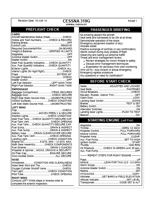
Review strategies for known threats to safetyDiscuss error management techniquesExpectation for advocacy from pilot monitoring Who will fly / duty division in actual emergency Emergency egress procedureAny questions or need for clarification? Seats………….........….…..ADJUSTED AND LOCKED Seat Belts……………...………………….…FASTENED Circuit Breakers……………………….….……...CHECK Elevator, Rudder, Aileron Trim...............................SET Cabin Door..........................................................LOCKCESSNA 310GNORMAL CHECKLISTExpected Taxi Route..................................REVIEWED Brakes……...…..TEST (do not ride brakes during taxi) Gyro Instruments/Compass.....PROPER OPERATION Engine Instruments..........................................CHECKBrakes……….………………………………………...SET Flight Controls………………….…..FREE & CORRECT Flight Instruments/GPS Flight Plan...….CHECK & SET Seats….............……….…..ADJUSTED AND LOCKED Seat Belts & Harnesses……………..………...SECURE Cabin Door.....................................................LOCKED Mixture Controls…………………………………….RICH Propeller Controls........................................HIGH RPM Throttles (one at a time)……………...……...1700 RPM Magnetos (max. 150 drop, 50 diff.)….………...CHECK Vacuum Pumps....(use vacuum source selector valve) Induction Heat..................................................CHECK Propellers……..EXERCISE (no lower than 1200 RPM) Engine Instruments & Ammeter………………..CHECK Oil Pressure..................................................30-60 PSI Throttles.....................................1000 RPM (verify idle) Fuel Selector...........................................L & R MAINS Pitot Heat…………………………………….CONSIDERElevator Trim…….………………..SET FOR TAKEOFF Induction Heat………….……….........…………...COLD Propellers....................................................HIGH RPM Aux. Boost Pumps...............................................LOW Wing Flaps……......….......….SET FOR TAKEOFF (0°) Radios and Avionics………………………………...SET Transponder…………..………….….CODE SET & ALT Landing Lights........................……...……………….ON Mixture…………….……………………..…………..RICH BRIEF PRIOR TO TAKING THE RUNWAYCross-Wind Correction…………....APPLY IF NEEDED Hold Brakes/Throttles...SLOWLY ADVANCE TO FULL Engine Instruments…………...….IN NORMAL RANGE Elevator Control……...LIFT NOSE WHEEL at 85 MPH --------- Expect to Break Ground at 95 MPH --------- Initial Climb Speed…...……………..……....…117 MPH Initial Heading...........................................DETERMINEProcedure in Case of Engine Failure:Pitch for best single-engine climb speed of 117 MPHLanding Gear.........................................UP (verify red) Climb Speed ….......130-140 MPH ABOVE 1000’ AGL Aux. Boost Pumps.................................................OFF Throttles.......................................SET 24 INCHES MP Propellers.....................................................2400 RPMPower….…......……...............................……PER POH Mixture…..…………...LEAN ENGINES SEPARATELY Trim.......................................ADJUST ONCE STABLE Landing Lights..………………………………..…….OFF Fuel Levels...................................................MONITOR Engine Instruments (EGTs, oil press/temp)............MONITORAirport Information…………………………..REVIEWED ATIS/AWOS/Local WX……………..……….OBTAINED Crosswind………………………...CONFIRMED <16 KT Landing Lights..………………………………………..ON Radio............................TUNED TO TOWER OR CTAF Transmit.............(10 nm out) POSITION AND INTENT Mixture Controls.........................ENRICH AS NEEDEDSeat Belts & Harnesses……………..………...SECURE Seats….........………….…..ADJUSTED AND LOCKED Fuel Selectors..........................................L & R MAINS Induction Heat.....................................................COLD Aux. Fuel Pumps.....................................................ON Wing Flaps………..……………………..…AS DESIRED Landing Gear................ (<140 MPH) DOWN AND GREEN Mixture…………………………………………..…..RICH Propeller Controls............FULL FORWARD ON FINAL Airspeed..……............................BLUELINE ON FINAL 95 MPH OVER THRESHOLD (flaps 30° max.)Wing Flaps…………..………………………………....UP Aux. Fuel Pumps....................................................OFF Mixture……………………………...…..LEAN FOR TAXI Lights………..…….................. LANDING LIGHTS OFF Pitot Heat…….…………………..…………………...OFFTransponder………………...………...CODE SET 1200 Storm Scope...........................................................OFF Throttles………………..…………..………….1000 RPM Avionics Master Switch………….…………………..OFF Mixtures.…………………………...……..IDLE CUTOFF Magnetos..........……..………….…………….……..OFF Alternators............……………….……………….....OFF Master Switch………………….……...……….…….OFF Control Lock………..............……….…..……..INSTALL Hobbs & Tach Numbers…….………………..RECORD Wheel Chocks……………………………….….INSTALL Post-Flight Inspection……CONDUCT WALKAROUND CLIMB CHECKTAXI CHECK INITIAL RUNUP CHECK CRUISE CHECKARRIVAL AREA CHECKBEFORE LANDING CHECKBEFORE TAKEOFF CHECK******* REQUIRED PRIOR TO ALL TAKEOFFS *******AFTER LANDING CHECKSECURING CHECKPAGE 2This checklist is a guide to coordinate Pilot Operating Handbook (POH),local procedures, and recognized best practices. The applicable POH remains the official documentation for this aircraft. The pilot in command (PIC) is responsible for complying with all items in the POH.TAKEOFF & LANDING CHARTS This checklist is to be used as a quick reference. The POH should always be consulted when time allows. The applicable POH remains the official documentation for this aircraft. The pilot in command (PIC) is responsible for complying with all items in the POH.NOTE: Takeoff and landing distance numbers shown below are the absolute minimumdistances demonstrated by a test pilot. Multiply all resulting distances from these charts by a factor of 1.5 to establish safe takeoff and landing distances to be used for your flight.CRUISE CHARTSNOTE: Additional cruise chart data for higher and lower altitudes can be found in the POH. The charts below are for quick reference at altitudes used in typical training flights.EMERGENCY CHECKLISTIMMEDIATE ACTION ITEMS ARE IN BOLD TYPEENGINE FAILUREDURING TAKEOFF BELOW 95 MPH1. Cut Power on Operative Engine2. Decelerate to a StopDURING TAKEOFF ABOVE 95 MPH WITH ROUGH TERRAIN AHEADThrottles................................FULL FORWARD Propeller Levers....................FULL FORWARD Landing Gear Switch...................................UP Inoperative Engine.....................VERIFY SIDE Propeller Lever...........FEATHER (inop engine) Initial Climb Speed....................103 MPH (Vx) Trim..........................ADJUST FOR 3-5° BANK INTO GOOD ENGINE Airspeed....................117 MPH WHEN CLEAR Flaps...............................UP IN INCREMENTS Secure Dead Engine:1. Aux. Fuel Pump..................................OFF2. Alternator Switch................................OFF3. Ignition Switch....................................OFF4. Mixture Lever.....................................OFF5. Fuel Selector (inop engine)................OFF6. Fuel Selector (good engine)........SELECT AS NEEDED TO MAINTAIN BALANCEDURING FLIGHTThrottles................................FULL FORWARD Propeller Levers....................FULL FORWARD Mixture Levers........ADJUST TO LOW RANGE Inoperative Engine.....................VERIFY SIDE Rudder.......TRIM FOR SINGLE-ENG. FLIGHTNOTE: Before securing the inoperative engine check fuel flow. If deficient turn on Aux. PumpFuel Tank Selector....MAIN TANK (unless low) CROSS-FLOW IF NEEDED Engine Instruments.........................MONITOR Failed Engine..........SHUTDOWN IF NEEDED Ignition Switches..................................CHECKNOTE: See POH guidance for securing the inoperative engine and/or for restarting an engine after feathering (page 4-6)SINGLE ENGINE CLIMBThrottle................................FULL FORWARD Propeller Lever....................FULL FORWARD Mixture Lever........ADJUST TO LOW RANGE Landing Gear Switch...................................UP Flaps..............................UP IN INCREMENTS Airspeed...................117 MPH WHEN CLEAR 103 MPH W/OBSTACLES Bank.........................5° INTO GOOD ENGINESee POH pages 4-7 and 4-8Airspeed.................APPROACH AT 103 MPH Landing Gear.....DELAY UNTIL FIELD MADE Flaps..................DELAY UNTIL FIELD MADE Airspeed………....117 MPH ON APPROACH 95 MPH ON FINAL Flare........HOLD EXTRA SPEED IF NEEDEDThrottle.........................................FULL OPEN Propeller Lever....................FULL FORWARD Landing Gear..................................RETRACT Flap Setting...............................................15° Climb Speed....................................117 MPH 103 MPH W/OBSTACLE Trim........................SET FOR S. ENG. CLIMB Flap Setting............RETRACT WHEN CLEARMaster Switch……...…………………..….OFF Vents/Cabin Air/Heat…………........CLOSED Fire Extinguisher……...………….ACTIVATEWARNING: Ventilate cabin after use of fire extinguisher.Land….…………….AS SOON AS POSSIBLEFor emergency exit, the left center cabin window can bejettisoned. Pull off the plastic cover over the emergency release ring under the window. Pull the ring to release the window retainers, then push the window out.FORCED LANDINGS C310GPAGE 1REVIEW POH EMERGENCY SECTION AFTER COMPLETING THIS CHECKLISTF L Y T H E A I R P L A N E I D E N T I F Y T H E P R O B L E M D O N O T H U R R YFLY THE AIRPLANE IDENTIFY THE PROBLEM DO NOT HURRYR e v i s i o n D a t e : 15 J U N 14 SINGLE-ENGINE LANDINGSINGLE ENGINE GO AROUNDCABIN FIRE OR SMOKE EMERGENCY EXITEMERGENCY CHECKLISTIMMEDIATE ACTION ITEMS ARE IN BOLD TYPEELECTRICAL FIREIN FLIGHTMaster Switch……………..……………….OFF Vents/Cabin Air/Heat.…………….…CLOSED Fire Extinguisher…………..………ACTIVATEWARNING: Ventilate cabin after use of fireextinguisher.Avionics Power Switch………...…….……..OFF All Other Switches (except ignition)….…...OFFIf fire appears to be out and electrical power is required for continued safe flight:Master Switch……………………………..….ONCircuit Breakers…....CHECK for faulty circuit - DO NOT RESET if breaker has tripped. Individual Radio Switches..…………..……OFF Avionics Power Switch……….……………..ON Radio/Electrical Switches…..ON one at a time until the short circuit is localized. Vents……...OPEN when fire is out completely Land…..…………….AS SOON AS POSSIBLEIN FLIGHTBoth Auxiliary Fuel Pumps.........................OFF Affected Engine..........SECURE AS FOLLOWS 1. Throttle..........................................CLOSE 2. Mixture...............................IDLE CUTOFF 3. Propeller...................................FEATHER 4. Fuel Selector.............OFF (feel for detent) 5. Magnetos...........................................OFF 6. Alternator...........................................OFF 7. Cowl Flap......................................CLOSE Cabin Heater.............................................OFF Land and evacuate the aircraft as soon as practical.ON THE GROUNDThrottles................................................CLOSE Brakes......................................AS REQUIRED Mixtures.....................................IDLE CUTOFF Battery.......................................................OFF Magnetos..................................................OFF Evacuate the airplane as soon as practical.EMERGENCY DESCENTThrottles...................................................IDLE Propellers............................FULL FORWARD Mixtures........................ADJUST AS NEEDED Wing Flaps..................................................UP Landing Gear..............................................UP Moderate Bank..................................INITIATE Airspeed...........................................220 KIASTURBULENT CONDITION SETTINGS Gear DOWN / Flaps 35 / Airspeed 158 MPHPitot Heat Switch……..…………………...ON Heading and/or Altitude………......CHANGE A heading change of 180° should return you to ice free conditions. Lower altitudes are normally warmer. Advise ATC if under IFR control.Cabin Heat Control……………....FULL OUT Cabin Air Control….ADJUST for max. flow Propeller Levers………...……....INCREASE RPM to minimize ice buildup on propellers. GPS……...…LOCATE NEAREST SUITABLE AIRPORT and plan to land there.WARNING: With extremely rapid ice buildup select a suitable off-airport landing site.Stall Speed will be significantly higher with ice accretion of 1/4 inch or more.Wing Flaps Do NOT extend as wing wake airflow change with flaps down could result in loss of elevator effectiveness.Forward Slip to land if needed for improved forward visibility.Approach at speeds higher than normal no-flap approach speeds depending on the amount of ice accumulation.SEE POH SECTION IVThis checklist is to be used as a quick reference. The POH shouldalways be consulted when time allows. The applicable POH remains the official documentation for this aircraft. The pilot in command (PIC) is responsible for complying with all items in the POH.ALWAYS REVIEW THE POH EMERGENCY SECTIONAFTER COMPLETING THIS CHECKLISTICING ENCOUNTER ENGINE / WING FIREPAGE 2OTHER EMERGENCIES C310GREVIEW POH EMERGENCY SECTION AFTER COMPLETING THIS CHECKLISTF L Y T H E A I R P L A N E I D E N T I F Y T H E P R O B L E M D O N O T H U R R YFLY THE AIRPLANE IDENTIFY THE PROBLEM DO NOT HURRY。
美国空军中意AETD发动机
美国空军中意AETD发动机作者:张晓军周军来源:《航空世界》2013年第02期2012年夏天,美国空军投资2.136亿美元,启动新一轮“自适应发动机技术研发(AETD)”项目,目标是为下一代航空发动机奠定基础,用以替代当前普遍使用的固定循环发动机。
无限繁荣的航空发动机市场美国空军在实践中发现,研发发动机比设计飞机获利更多,随之启动了一系列长期发动机技术研发项目。
60年代,美国空军启动了“先进涡轮发动机气体发生器(ATEGG)”研发计划,改变专门研制一种发动机的方式,在材料、风扇、压缩机、发动机工作模拟环境等分支技术领域全面开花。
培养先进发动机技术团队最终成为美国空军的发展战略,空军系统司令部(AFSC)成立了推进系统委员会,专门负责发动机研发项目,统筹管理所有的主要发动机制造商。
1974年,在经历多次政治性争论后,美国通用电气公司(GE)与法国斯奈克玛(snecma)公司各出资50%创立了联合投资公司,生产CFM56系列发动机。
CFM56发动机直接在F101发动机核心机的基础上发展而来,为了得到这项技术,法国王室贵族还向美国支付了一部分合同费用。
CFM56发动机在商业领域也非常成功,截止2011年,联合投资公司已经向全世界客户生产交付了22208台CFM56系列发动机。
1969年普·惠公司弗雷德里克·G·格鲁启动的“钛扩散焊接”项目是ATEGG研发计划的样板工程,由空军航空推进装置实验室的涡轮发动机分部出资,欧内斯特·c·辛普森主持。
辛普森这样的关键人物长期负责相关项目,保持了研发的延续性。
美国空军也并非先进发动机的唯一市场,70年代中期,美国空军和海军合作启动了联合技术标准发动机(JTDE)项目,研发范围包括所有的发动机零部件。
通用电气公司还得到了一项价值9300万美元的全面研制合同,为期两年,发动机正式编号为F110,与普·惠公司F100发动机的改进型竞争,用于新生产的F-15和F-16战斗机。
CTSO-C145e 《使用星基增强系统(SBAS)增强全球定位系统的机载导航传感器》英文翻译版
Number:CTSO-C145eApproved by:Xu ChaoqunChina Civil Aviation Technical Standard OrderAirborne Navigation Sensors Using The Global Positioning SystemAugmented By The Satellite Based Augmentation System (SBAS)1. Purpose.This China Civil Aviation Technical Standard Order (CTSO) is for manufacturers applying for airborne navigation sensors using the global positioning system (GPS) augmented by the satellite based augmentation system (SBAS) CTSO authorization (CTSOA). This CTSO prescribes the minimum performance standards(MPS) that airborne navigation sensors using the GPS augmented by the SBAS must first meet for approval and identification with the applicable CTSO marking.2. Applicability.This CTSO affects new application submitted after its effective date.Major design changes to article approved under this CTSO will require a new authorization in accordance with section 21.353 of CCAR-21R4.3. RequirementsNew models of airborne navigation sensors using the GPS augmented by the SBAS identified and manufactured on or after the effective date of this CTSO must meet the MPS qualification and documentation requirements for functional equipment Class Beta in RTCA, Inc. document RTCA/DO-229E, Minimum Operational Performance Standards for Global Positioning System/Satellite-Based Augmentation System Airborne Equipment dated December 15, 2016, Section 2.1. Class Beta equipment is defined in RTCA/DO-229E, Section 1.4 and Appendix 2 adds a new section 1.8.3.Note: Manufacturers have the option to use the RTCA/DO-229E change described in Appendix 3. The change is based on a past commonly granted deviation.a. An alternate method for applicants is to apply for CTSO-C145e using their existing approved design data plus additional substantiation data showing compliance with the changes in RTCA/DO-229E. The three areas where requirements changed are: 1) expanding the SBAS pseudorandom noise (PRN) codes (i.e., PRN range of 120 thru 158); 2) ensuring a graceful degradation to GPS-only operations; and, 3) prohibiting use of the broadcast Navigation Message Correction Table.Note 1: It is not necessary for applicants to re-submit previously approved deviations. Previously approved deviations, and any limitations,will apply to the CTSO-C145e CTSOA.Note 2: Applicants with Class 1 and 2, revision ‘b’ equipment must not have claimed the 3db broadband intrasystem noise credit.b. CTSO-C145e applicants have the option to use a CTSO-C204a SBAS CCA functional sensor. Applicants choosing to use a CTSO-C204a SBAS CCA can take certification compliance credit by virtue of the CTSO-C204a CTSOA for:z Meeting the MPS section 2.1 requirements;z The hardware/software qualification;z The failure condition classification; and,z MPS section 2.5 performance testing (functional qualification) except those specified in Appendix 1 of this CTSO.c. The CTSO-C145e applicant using a CTSO-C204a SBAS CCA functional sensor shall perform the testing described in Appendix 1 and satisfy the remaining paragraphs in this CTSO not covered by the bullets above to receive a CTSO-C145e CTSOA.Note: The end-use manufacturer using a CTSO-C204a SBAS CCA functional sensor as part of their CTSO-C145e application assumes full responsibility for the design and function under their CTSO-C145e authorization.d. Functionality.This CTSO’s standards apply to equipment intended to provideposition, velocity, time information for a navigation management unit application that outputs deviation commands keyed to a desired flight path, or a non-navigation application such as automatic dependent surveillance-broadcast (ADS-B) or terrain awareness and warning system (TAWS). In navigation applications, pilots or autopilots will use the deviations output by the navigation management unit to guide the aircraft. In non-navigation applications, the position, velocity, time outputs will provide the necessary input for the end-use equipment. These TSO standards do not address integration issues with other avionics.e. Failure Condition Classifications.(1) Failure of the function defined in paragraph 3.d resulting in misleading information for en route, terminal, approach lateral navigation (LNA V), and approach LNA V/vertical navigation (VNA V) position data is a Major failure condition.(2) Failure of the function defined in paragraph 3.d resulting in misleading information for approach localizer performance without vertical guidance (LP), and approach localizer performance with vertical guidance (LPV) position data is a Hazardous failure condition.(3) Loss of the function defined in paragraph 3.d for enroute through approach LP/LPV position data is a Major failure condition.(4) Design the system to at least these failure condition classifications.f. Functional Qualification.(1) Demonstrate the required functional performance under the test conditions specified in RTCA/DO-229E, Section 2.5, or(2) When using a CTSO-C204a SBAS CCA functional sensor, demonstrate the required performance under the test conditions in appendix 1 of this CTSO.g. Environmental Qualification.Demonstrate the required performance under the test conditions specified in RTCA/DO-229E, Section 2.4 using standard environmental conditions and test procedures appropriate for airborne equipment. RTCA/DO-229E requires the use of RTCA/DO-160E, Environmental Conditions and Test Procedures for Airborne Equipment, dated December 9, 2004, Sections 4.0 through 8.0 and 10.0 through 25.0. You may use a different standard environmental condition and test procedure than RTCA/DO-160E, provided the standard is appropriate for the SBAS sensor.Note1: The use of RTCA/DO-160D (with Changes 1 and 2 only, incorporated) or earlier versions is generally not considered appropriate and will require substantiation via the deviation process as discussed in paragraph 3.k of this CTSO.Note 2: Applicants using a CTSO-C204a SBAS CCA sensor must perform the environmental qualification with the SBAS CCA in theend-use equipment.h. Software Qualification.If the article includes software, develop the software according to RTCA/DO-178C, Software Considerations in Airborne Systems and Equipment Certification, dated December 13, 2011, including referenced supplements as applicable, to at least the software level consistent with the failure condition classification defined in paragraph 3.e of this CTSO. The applicant may also develop the software according to RTCA/DO-178B, dated December 1, 1992.(2) Applicants using a CTSO-C204a SBAS CCA sensor may use CTSO-C204a as substantiation for the software qualification.i. Electronic Hardware Qualification.If the article includes complex custom airborne electronic hardware, develop the component according to RTCA/DO-254, dated April 19, 2000, Design Assurance Guidance for Airborne Electronic Hardware, to at least the design assurance level consistent with the failure condition classification defined in paragraph 3.e of this CTSO. For custom airborne electronic hardware determined to be simple, RTCA/DO-254, paragraph1.6 applies.(2) Applicants using a CTSO-C204a SBAS CCA sensor may use CTSO-C204a as substantiation for the hardware qualification.j. Barometric-aided Fault Detection and Exclusion (FDE).If the equipment uses barometric-aiding to enhance FDE availability, then the equipment must meet the requirements in RTCA/DO-229E, appendix G.k. Deviations.For using alternative or equivalent means of compliance to the criteria in this CTSO, the applicant must show that the equipment maintains an equivalent level of safety. Apply for a deviation under the provision of 21.368(a) in CCAR-21R4.4. Marking.a. Mark at least one major component permanently and legibly with all the information in 21.423(b) of CCAR-21R4. The marking must include the serial number.b. Also, mark the following permanently and legibly, with at least the manufacturer’s name, subassembly part number, and the CTSO number:(1) Each component that is easily removable (without hand tools); and,(2) Each subassembly of the article that manufacturer determined may be interchangeable.c. If the article includes software and/or airborne electronic hardware, then the article part numbering scheme must identify the software andairborne electronic hardware configuration. The part numbering scheme can use separate, unique part numbers for software, hardware, and airborne electronic hardware.d. The applicant may use electronic part marking to identify software or airborne electronic hardware components by embedding the identification within the hardware component itself (using software) rather than marking it on the equipment nameplate. If electronic marking is used, it must be readily accessible without the use of special tools or equipment.e. At least one major component must be permanently and legibly marked with the operational equipment class (for example, Class 2) as defined in RTCA/DO-229E, Section 1.4.2.5. Application Data Requirements.The applicant must furnish the responsible certification personnel with the related data to support design and production approval. The application data include a statement of conformance as specified in section 21.353(a)(1) in CCAR-21R4 and one copy each of the following technical data:a. A Manual(s) containing the following:(1) Operating instructions and equipment limitations sufficient to describe the equipment’s operational capability.(2) Describe in detail any deviations.(3) Installation procedures and limitations sufficient to ensure that the SBAS sensor, when installed according to the installation or operational procedures, still meets this CTSO’s requirements. Limitations must identify any unique aspects of the installation. The limitations must include a note with the following statement:“This article meets the minimum performance and quality control standards required by a CTSO. Installation of this article requires separate approval.”(4) For each unique configuration of software and airborne electronic hardware, reference the following:(a) Software part number including revision and design assurance level;(b) Airborne electronic hardware part number including revision and design assurance level;(c) Functional description.(5) A summary of the test conditions used for environmental qualifications for each component of the article. For example, a form as described in RTCA/DO-160G, Environmental Conditions and Test Procedures for Airborne Equipment, Appendix A.(6) Schematic drawings, wiring diagrams, and any other documentation necessary for installation of the SBAS sensor.(7) List of replaceable components, by part number, that makes up the SBAS sensor. Include vendor part number cross-references, when applicable.(a) If the equipment can satisfy the requirements of RTCA/DO-229E only when used with a particular antenna, make the use of that antenna (by part number) a requirement on the installation. Include this requirement in the installation manual (IM) as a limitation.(b) If the equipment is installed with a standard antenna, include maximum tolerable currents and voltages into the antenna port. See CTSO-C144a, Passive Airborne Global Navigation Satellite System (GNSS) Antenna, applicable only to operational Class 1 equipment, or CTSO-C190, Active Airborne Global Navigation Satellite System (GNSS) Antenna, applicable to all equipment operational classes.b. Instructions covering periodic maintenance, calibration, and repair, for the continued airworthiness of the SBAS sensor. Include recommended inspection intervals and service life, as appropriate.c. If not using a CTSO-C204a SBAS functional sensor and the article includes software: a plan for software aspects of certification (PSAC), software configuration index, and software accomplishment summary.d. If not using a CTSO-C204a SBAS functional sensor and the article includes simple or complex custom airborne electronic hardware: aplan for hardware aspects of certification (PHAC), hardware verification plan, top-level drawing, and hardware accomplishment summary (or similar document, as applicable).e. A drawing depicting how the article will be marked with the information required by paragraph 4 of this CTSO.f. Adequate specifics on the interface between the SBAS sensor and other systems to ensure proper functioning of the integrated system. If the equipment depends on any external inputs (like baro-aided FDE) to satisfy the requirements of RTCA/DO-229E, make those inputs a requirement in the installation. Include this requirement in the IM as a limitation.g. If the software qualification limits eligibility of the equipment to certain aircraft types, identify the qualification level, and that the equipment is not eligible for all aircraft types. For example, RTCA/DO-178B (or RTCA/DO-178C) Level C software may be associated with a hazardous failure condition for certain aircraft types. Identify other limitations applicable to the failure condition classification, for example, that two installed units are necessary.h. If the equipment has not been demonstrated as compatible with satellite communications (SatCom) record in the limitations section that the equipment should not be installed in SatCom equipped aircraft.i. Identify functionality or performance contained in the article notevaluated under paragraph 3 of this CTSO (that is, non-CTSO functions). Non-CTSO functions are accepted in parallel with the CTSO authorization. For those non-CTSO functions to be accepted, you must declare these functions and include the following information with your CTSO application:(1) Description of the non-CTSO function(s), such as performance specifications, failure condition classifications, software, hardware, and environmental qualification levels. Include a statement confirming that the non-CTSO function(s) do not interfere with the article’s compliance with the requirements of paragraph 3.(2) Installation procedures and limitations sufficient to ensure that the non-CTSO function(s) meets the declared functions and performance specification(s) described in paragraph 5.i.(1).(3) Instructions for continued performance applicable to the non-CTSO function(s) described in paragraph 5.i.(1).(4) Interface requirements and applicable installation test procedures to ensure compliance with the performance data defined in paragraph 5.i.(1).(5) Test plans, analysis and results, as appropriate, to verify that performance of the hosting CTSO article is not affected by the non-CTSO function(s).(6) Test plans, analysis and results, as appropriate, to verify thefunction and performance of the non-CTSO function(s) as described in paragraph 5.i.(1).(7) Alternatively, identify non-CTSO functionality or performance contained in the article not evaluated under paragraph 3 and submit previously accepted data for the non-CTSO function for acceptance in parallel with this CTSO application.j. The quality system description required by section 21.358 of CCAR-21R4, including functional test specifications. The quality system should ensure that it will detect any change to the approved design that could adversely affect compliance with the CTSO MPS, and reject the article accordingly.k. Material and process specifications list.l. List of all drawings and processes (including revision level) that define the article’s design.m. Manufacturer’s CTSO qualification report showing results of testing accomplished according to paragraph 3.f of this CTSO.6. Manufacturer Data Requirements.Besides the data given directly to the authorities, have the following technical data available for review by the authorities:a. Functional qualification specifications for qualifying each production article to ensure compliance with this CTSO.b. Equipment calibration procedures.c. Schematic drawings.d. Wiring diagrams.e. Material and process specifications.f. The results of the environmental qualification tests conducted according to paragraph 3.g of this CTSO.g. If the article includes software, the appropriate documentation defined in the version of RTCA/DO-178 or RTCA/DO-178C specified by paragraph 3.h of this CTSO, including all data supporting the applicable objectives in Annex A, Process Objectives and Outputs by Software Level.h. If the article includes complex custom airborne electronic hardware, the appropriate hardware life cycle data in combination with design assurance level, as defined in RTCA/DO-254, Appendix A, Table A-l. For simple custom airborne electronic hardware, the following data: test cases or procedures, test results, test coverage analysis, tool assessment and qualification data, and configuration management records, including problem reports.i. If not using CTSO-C204a, all the data necessary to evaluate the geo stationary (GEO) satellite bias as defined in RTCA/DO-229E, Section 2.1.4.1.5.j. If the article contains non-CTSO function(s), the applicant mustalso make available items 6.a through 6.h as they pertain to the non-CTSO function(s).7. Furnished Data Requirements.a. If furnishing one or more articles manufactured under this CTSO to one entity (such as an operator or repair station), provide one copy or technical data and information specified in paragraphs 5.a and 5.b of this CTSO. Add any data needed for the proper installation, certification, use, or for continued compliance with the CTSO, of the SBAS sensor.b. If the article contains declared non-CTSO function(s), include one copy of the data in paragraphs 5.i.(1) through 5.i.(4).8. Availability of Referenced Documents.Order RTCA documents from:Radio Technical Commission for Aeronautics, Inc.1150 18th Street NW, Suite 910, Washington D.C. 20036You may also order them online from the RTCA Internet website at: .APPENDIX 1. END-USE EQUIPMENT MANUFACTURER TESTS FOR SBAS CCA FUNCTIONAL POSITION, VELOCITY, TIME (PVT) SENSORS USED FOR NA VIGATION AND NON-NA VIGATION APPLICATIONS1. Scope.This appendix describes the required supplementary equipment level testing, in addition to the environmental testing of RTCA/DO-229E, section 2.4, required by the end-use equipment manufacturer to receive a CTSO-C145e Class Beta authorization when using a CTSO-C204a SBAS CCA functional sensor. These test procedures are intended to streamline and simplify the CTSO-C145e authorization process for the end-use equipment manufacturer by allowing credit for the design and selected testing done at the SBAS CCA functional sensor level. However, the end-use equipment manufacturer retains full responsibility for the design and control of the article per their CTSO-C145e CTSOA.2. General Principles.(a) Testing methods for GPS/SBAS equipment have been standardized by RTCA/DO-229E and serve as the basis for CTSO-C145e. RTCA/DO-229E was written with the perspective of equipment that canbe installed on aircraft. Section 2.4 specifically addresses the issues of the environment in which the equipment operates and provides approved test methods to validate performance in this environment. Section 2.4represents RTCA consensus in identifying which RTCA/DO-229E requirements are sensitive to environmental effects. These requirements are listed in the environmental tables referenced in section 2.4.1.(b) The determination that a MOPS requirement is susceptible to the environment does not depend on whether or not the implementation is a CCA within some host equipment. This is the same concept as an equipment enclosure designed to protect against a benign environment compared to one designed for a severe environment; the identification of susceptible requirements is the same.(c) Therefore this appendix uses the tables of RTCA/DO-229E, section 2.4.1 to identify the MOPS requirements susceptible to environmental affects for an SBAS CCA functional sensor in the end-use equipment. The focus is on the change in environment seen by the SBAS CCA functional sensor as a result of its installation in the end-use equipment. For example, other components inside the end-use equipment may radiate RF energy that could interfere with the GPS functions; therefore the ambient testing done at CCA level is not equivalent to tests done in the end-use equipment. This is the basis for defining the RTCA/DO-229E, section 2.5 performance tests that need to be repeated by the end-use equipment manufacturer.(d) The Class Beta environmental table referenced in RTCA/DO-229E, section 2.4.1 are the prime source to determine theMOPS performance requirements susceptible to environmental conditions. Based on the table, the susceptible requirements can be grouped in two categories: those susceptible to most types of environmental conditions (described in section 3) and those susceptible to just a few (described in section 4).Note: The Tables for Class Beta-1, -2, and -3 equipment identify similar requirements susceptible to the installed environment. The only difference is the applicable MOPS requirements consistent with the operational class (i.e., class -1, - 2, or -3).3. Performance Requirements Susceptible to Most Environmental Conditions.The RTCA/DO-229E requirements for Accuracy (2.1.3.1, 2.1.4.1, and 2.1.5.1) and Sensitivity and Dynamic Range (2.1.1.10) are sensitive to most environmental conditions. However, these requirements are linked to the message loss rate requirement in 2.1.1.3.2. Section 3.1 and 3.2 below identifies the testing end-use equipment manufacturers are required to repeat to demonstrate the SBAS CCA functional sensor continues to meet the Accuracy, Dynamic Range, and Message Loss Rate performance requirements after installation in the end-use equipment. All tests will be run under conditions where the end-use equipment functions are fully enabled to create the worst-case environment.3.1 RTCA/DO-229E, 2.5.8 Accuracy Test.(a) The accuracy test described in section 2.5.8 is actually a joint test covering both accuracy, and sensitivity and dynamic range. This joint testing also applies under environment as stated in section 2.4.1.1.5 with environmental adaptation as described in section 2.4.1.1.1.(b) The demonstration of accuracy is done in accordance with section 2.5.8.1 only for the test case with a broadband external interference noise. This test must be repeated when the CCA is installed in the end-use equipment and it is sufficient to perform it using broadband interference.(1) The environmental testing is limited to broadband interference as it represents the worst case signal to noise condition which is the most sensitive to environmental effects. This applies equally to the environment for the CCA created by the end-use equipment.(2) Section 2.5.8 contains a measurement accuracy test in 2.5.8.1 with the detailed test procedure in 2.5.8.2. The 2.5.8.1 test must be run under the worst case environment identified in the “Additional considerations for internal interference sources” section below. The measurement accuracy testing can be combined with the message loss rate testing in 2.5.2.1.(3) Section 2.5.8.3 is a 24-Hour actual satellite accuracy test. The section 2.5.8.3 test exposes the equipment to a variety of signal conditions and data processing conditions over varying satellite geometrythat will increase confidence that no unforeseen interactions between components within the end-use equipment and the SBAS CCA functional sensor goes undetected. The 24 hr testing in 2.5.8.3 can be combined with the 24 hr message loss rate testing in 2.5.2.4 (see Additional Considerations for Internal Interference Sources section).(4) Section 2.5.8.4 (SBAS Tracking Bias) is an analysis of the GPS hardware and is therefore not necessary to repeat at the end-use equipment level as long as no extra RF components that affect the RF filtering response are inserted in the RF path. Otherwise the end-use equipment manufacturer must repeat the SBAS Tracking Bias test as well.(c) The test threshold is relaxed from 110% to 125% as specified in table 2-25 of the 2.5.8.2.1 test procedure to shorten test time. However, Section 2.5.8 testing (excluding the SBAS Tracking Bias test in 2.5.8.4) for the CCA in the end-use equipment shall be under ambient conditions per section 2.5 with the 110% test pass threshold for maximum test sensitivity.(d) The Section 2.5.8 testing (excluding the SBAS Tracking Bias test in 2.5.8.4) will be repeated against the accuracy requirement consistent with the desired operational class (i.e., 2.1.3.1, 2.1.4.1, and 2.1.5.1 accuracy requirements as appropriate).(e) Only the broadband external interference noise test case usingminimum satellite power will be executed in most cases to shorten test time. Section 2.5.8.1 testing will be repeated for both minimum and maximum satellite power for the worst case environment only.3.2 RTCA/DO-229E, 2.5.2 Message Loss Rate Test.(a) Section 2.5.2 specifies the message loss rate test for the 2.1.1.3.2 message loss rate requirement. This test is conducted in conjunction with the 2.5.8 accuracy testing. Section 2.5.2.2 defines the test procedure to collect data verifying the SBAS message loss rate in the presence of interference using the test cases where the SBAS satellite is at minimum power. Section 2.5.2.3 defines the pass/fail criteria.(b) The test in section 2.5.2.2 will be performed during the measurement accuracy broadband interference test case described in paragraph 3.1.(c) The test procedure in section 2.5.2.4.1 is run in conjunction with the 2.5.8.3 24-hour accuracy test. Section 2.5.2.4.2 defines the pass/fail criteria for the test case described in paragraph 3.1(b)(3).4. Performance Requirements Partially Susceptible to Environmental Conditions.(a) The class Beta tables (tables 2-14, 2-16, and 2-18) in section2.4.1 of RTCA/DO-229E indicates the requirements for Initial Acquisition Time (2.1.1.7) and Satellite Reacquisition Time (2.1.1.9) are sensitive to four environmental conditions: Icing, Lightning InducedTransient Susceptibility, Lightning Direct Effects, and Normal/Abnormal Operating Conditions. The requirements for Loss of Navigation (2.1.1.13.2, 2.1.4.12.2, and 2.1.5.12.2) and Loss of Integrity (2.1.1.13.1, 2.1.4.12.1, and 2.1.5.12.1) are sensitive to low and high operating temperature.(b) The Lightning Induced Transient Susceptibility, Lightning Direct Effects, or Icing environmental conditions are not pertinent to the environment created by the end-use equipment relative to the SBAS CCA functional sensor. However, the end-use equipment manufacturer remains responsible for meeting the overall environmental qualification at the end-use equipment level.(c) Loss of navigation and loss of integrity indications are limited to temperature testing and the information in RTCA/DO-229E, sections 2.4.1.1.2 and 2.4.1.1.3 is appropriate. The purpose is to ensure that the interface used to indicate the loss of navigation is functional under environmental conditions after the SBAS CCA functional sensor is installed in the end-use equipment. Sections 2.4.1.1.2 and 2.4.1.1.3 indicate that any source that generates the indication can be used since it is the interface and not the detection mechanism that is verified. The temperature testing done at the end-use equipment level is the worst-case scenario. It is not necessary to repeat the CCA level test at room temperature in the end-use equipment since the environmentalqualification adequately addresses testing for these requirements.(d) RTCA/DO-160E section 16 relates to aircraft power supply (refer to TSO paragraph 3.g for environmental qualification requirements). Sections 16.5.1.2 and 16.6.1.2 are for supply voltage modulation (ac) /ripple (dc). Given the potential susceptibility of the SBAS CCA functional sensor to power supply noise, it is prudent to repeat tests at the end-use equipment level on this basis.(e) Sections 4.1 and 4.2 identify the testing end-use equipment manufacturers are required to repeat to demonstrate the SBAS CCA functional sensor continues to meet the Acquisition Time and Reacquisition Time performance requirements relative to Normal/Abnormal Operating Conditions after installation in the end-use equipment. All tests will be run under conditions where the end-use equipment functions are fully enabled to create the worst-case environment.4.1 2.5.4 Initial Acquisition Test Procedures.The information in RTCA/DO-229E, section 2.4.1.1.4 on the initial acquisition test in section 2.5.4 applies. The end-use equipment manufacturer shall repeat the initial acquisition testing described in RTCA/DO-229E, section 2.5.4.4.2 2.5.6 Satellite Reacquisition Time Test.The end-use equipment manufacturer is required to repeat the。
国际民航组织飞机型号代码国际民航组织飞机型号代码
国际民航组织飞机型号代码普通旅客在航班时刻表等民航宣传品上看到的机型栏目所列机型可能并不是我们常见的机型名称,而是一些你可能不明白代码,在民航内部的航行通告、动态传递中机型也经常使用一些代码表示,这些代码实际上不是随意编写的,而是国际民航组织规定的飞机型号代码,下面就列举部分常见的、在我国空域可能出现的民航机型型号代码,更多请访问国际民航组织相关页面资料说明:飞机型号代码:1.飞机型号代码由不超过四位的数字、字母组成,尽量代表出飞机的制造厂商、型号等资料,易用被空中管制判读信息,原则上是从飞机的具体型号上抽取而来。
2.飞机型号代码一经指定,不在更改,即使生产该型号飞机的制造厂商更名、变更所有权3.某飞机机型的具体型号原则上不再指定新的代码,除非这个改进型号的性能变化较大,按原有标准判读会影响到空中管制4.“ZZZZ”:特殊代码,表示该机型尚未指定代码5.国际民航组织建议的轻型、中型、重型飞机划分标准,是在航空管制方面很重要的标准,涉及到飞机尾流对后续飞机的影响,直接关系到航空安全轻型飞机(L:Light):按相关程序批准的飞机型号合格证上,最大起飞重量7吨或以下中型飞机(M:Medium):按相关程序批准的飞机型号合格证上,最大起飞重量7吨以上,136吨以下重型飞机(H:Heavy):按相关程序批准的飞机型号合格证上,最大起飞重量136吨或以上型号代码具体型号参考译名机型特点简介制造商代码备注(本站相关)AN12An-12 安12 四发涡桨中型ANTONOVAN22An-22 /Antheus 安22 四发涡桨重型ANTONOVAN24An-24 安24 双发涡桨中型ANTONOVAN24Y-7系列、MA60 运7/新舟60双发涡桨中型XIANAN32An-32 /Sutlej/Firekiller 安32 双发涡桨中型ANTONOVAN70An-70 安70 四发涡桨中型ANTONOVAN72An-72/74 安72/74 双发涡扇中型ANTONOVA124An-124 /Ruslan 安124 四发涡扇重型ANTONOVA140An-140 安140 双发涡扇中型ANTONOVA225An-225 /Mriya 安225 六发涡扇重型ANTONOVAT43ATR42-300系列双发涡桨中型AI(R)AT44ATR42-400 双发涡桨中型AI(R)AT45ATR42-500 双发涡桨中型AI(R)AT72ATR72 双发涡桨中型AI(R)A30B A-300B2系列、C4-100 空中客车双发涡扇重型AIRBUSA30B A-300B4-100/200 双发涡扇重型AIRBUSA3ST A-300ST Beluga 双发涡扇重型AIRBUSA3ST A-300ST SuperTransporter双发涡扇重型AIRBUSA306A-300B4/C4/F4-600 双发涡扇重型AIRBUSA310A-310系列双发涡扇重型AIRBUSA318A-318 双发涡扇中型AIRBUSA319A-319、A-319 ACJ 双发涡扇中型AIRBUSA320A-320 双发涡扇中型AIRBUSA321A-321 双发涡扇中型AIRBUSA332A-330-200 双发涡扇重型AIRBUSA333A-330-300 双发涡扇重型AIRBUSA342A-340-200 四发涡扇重型AIRBUSA343A-340-300 四发涡扇重型AIRBUSA345A-340-500 四发涡扇重型AIRBUSA346A-340-600 四发涡扇重型AIRBUSB190Beech 19000 比奇双发涡桨中型BEECHBE10Beech 100 King Air 空中国王双发涡桨轻型BEECHBE20Beech 200 Super KingAir双发涡桨轻型BEECHBE30Beech 300 Super KingAir双发涡桨轻型BEECHB350Beech Super King Air350双发涡桨轻型BEECHBE99Beech 99/ Airliner 双发涡桨轻型BEECHB212Bell Anafa/212 贝尔双发涡桨直升机BELLB412Bell Arapaho/412Sentinel双发涡桨直升机BELLB214Bell 214A/B/C 双发涡桨直升机BELLB461BAe-146-100 四发涡扇中型BRITISHAEROSPACEB462BAe-146-200 四发涡扇中型BRITISHAEROSPACEB463BAe-146-300 四发涡扇中型BRITISHAEROSPACEB701707-100 波音四发涡扇中型BOEINGB703707-300 四发涡扇重型BOEINGB722727-200 三发涡扇中型BOEINGB712717-200 双发涡扇中型BOEINGB731737-100 双发涡扇中型BOEINGB732737-200/200Surveiller 双发涡扇中型BOEINGB733737-300 双发涡扇中型BOEINGB734737-400 双发涡扇中型BOEINGB735737-500 双发涡扇中型BOEINGB736737-600 双发涡扇中型BOEINGB737737-700/BBJ、BBJ 双发涡扇中型BOEINGB738737-800、BBJ2 双发涡扇中型BOEINGB739737-900 双发涡扇中型BOEINGB741747-100 四发涡扇重型BOEINGB742747-200 四发涡扇重型BOEINGB743747-300 四发涡扇重型BOEINGB744747-400 (international) 四发涡扇重型BOEINGB74D747-400 (domestic) 四发涡扇重型BOEINGB74S747SP 四发涡扇重型BOEINGB74R747SR 四发涡扇重型BOEINGBSCA747SCA Shuttle Carrier 四发涡扇重型BOEINGB752757-200 双发涡扇中型BOEINGB753757-300 双发涡扇中型BOEINGB762767-200 双发涡扇重型BOEINGB763767-300 双发涡扇重型BOEINGB764767-400 双发涡扇重型BOEINGB772777-200 双发涡扇重型BOEINGB773777-300 双发涡扇重型BOEINGC120Cessna 120 塞斯纳单发活塞轻型CESSNAC150Cessna A150 Aerobat 单发活塞轻型CESSNAC172Cessna 172/172Skyhawk单发活塞轻型CESSNAC182Cessna Skylane 单发活塞轻型CESSNAC82R Cessna Skylane RG 单发活塞轻型CESSNAC208Cessna 208Cargomaster单发活塞轻型CESSNAC525Cessna CitationJet(525)/CJ1双发涡扇轻型CESSNAC25A Cessna Citation CJ2 双发涡扇轻型CESSNAC560Cessna Citation 5 UltraEncore双发涡扇中型CESSNAC550Cessna Citation S2 双发涡扇轻型CESSNAC56X Cessna Citation Excel 双发涡扇中型CESSNAC650Cessna Citation 6/7 双发涡扇中型CESSNAC750Cessna Citation 10 双发涡扇中型CESSNACL60Challenger 600/601/604 双发涡扇中型CANADAIRCRJ1Regional Jet RJ-100 双发涡扇中型CANADAIRCRJ2Regional Jet CRJ-200 双发涡扇中型CANADAIRCRJ7Regional Jet CRJ-700 双发涡扇中型CANADAIRCRJ9Regional Jet CRJ-900 双发涡扇中型CANADAIRD228Dornier 228 双发涡桨轻型DORNIERD328Dornier 328 双发涡桨中型DORNIERDC10DC-10 三发涡扇重型MCDONNELLDOUGLASDC85DC-8-50 Jet Trader 四发涡扇轻型DOUGLASDC91DC-9-10 双发涡扇中型DOUGLASDC93DC-9-30 双发涡扇中型DOUGLASDHC4DHC-4 /CV-2Caribou 双发活塞中型DEHAVILLANDCANADADHC5C-115 /CV-7Buffalo 双发涡桨中型DEHAVILLANDCANADADHC6 DHC-6/C-138 Twin Otter 双发涡桨中型DEHAVILLANDCANADADHC7Dash 7 四发涡桨中型DEHAVILLANDCANADADH8A DHC-8-100/Dash 8 双发涡桨中型DEHAVILLANDCANADADH8B DHC-8-200/Dash 8 双发涡桨中型DEHAVILLANDCANADADH8C DHC-8-300/Dash 8 双发涡桨中型DEHAVILLANDCANADADH8D DHC-8-400/Dash 8 双发涡桨中型DEHAVILLANDCANADAE110EMB-110 Bandeirante 双发涡桨轻型EMBRAERE120EMB-120 Brasilia 双发涡桨中型EMBRAERE135EMB-135 双发涡扇中型EMBRAERE145EMB-145AEWC/LR/ER 双发涡扇中型EMBRAERE45X EMB-145XR 双发涡扇中型EMBRAERE170ERJ-170/175 双发涡扇中型EMBRAERE190ERJ-190/195 双发涡扇中型EMBRAERFA10Falcon 10 双发涡扇中型DASSAULTFA20Falcon 20 双发涡扇中型DASSAULTFA50Falcon 50 三发涡扇中型DASSAULTF900Falcon 900 三发涡扇中型DASSAULTF2TH Falcon 2000 双发涡扇中型DASSAULTF50Fokker 50 MaritimeEnforcer双发涡桨中型FOKKERF60Fokker 60 双发涡桨中型FOKKERF70Fokker 70 双发涡扇中型FOKKERF100Fokker 100 双发涡扇中型FOKKERGLF3C-20A/B/C/D/EGulfstream 3 G-1159AGulfstream 3/SRA-1双发涡扇中型GULFSTREAMGLF4C-20F/G/H Gulfstream4G-1159C Gulfstream4/SP/SRA 4双发涡扇中型GULFSTREAMGLF5C-37 Gulfstream 5G-1159D Gulfstream 5双发涡扇中型GULFSTREAMGLEX BD-700 Global Express 双发涡扇中型GULFSTREAMCL30Challenger 300 双发涡扇中型GULFSTREAMGL5T Global 5000 双发涡扇中型GULFSTREAMH25B BAe-125-700/800 双发涡扇中型BRITISHAEROSPACEIL76Il-76/78/82 四发涡扇重型ILYUSHINIL86Il-86 四发涡扇重型ILYUSHINIL96Il-96 四发涡扇重型ILYUSHINI114Il-114 双发涡桨中型ILYUSHINJ328328JET Envoy 3 双发涡扇中型FAIRCHILDDORNIERJ728728JET 双发涡扇中型FAIRCHILDDORNIERJS32Jetstream Super 31 双发涡扇中型BRITISHAEROSPACEJS41Jetstream 41 双发涡扇中型BRITISHAEROSPACEJS20Jetstream 200 双发涡扇轻型BRITISHAEROSPACELJ35Learjet 35 双发涡扇中型LEARJETLJ40Learjet 40 双发涡扇中型LEARJETLJ45Learjet 45 双发涡扇中型LEARJETLJ55Learjet 50 双发涡扇中型LEARJETLJ60Learjet 60 双发涡扇中型LEARJETL101L-1011 TriStar 三发涡扇重型LEARJETMD11MD-11 三发涡扇重型MCDONNELLDOUGLASMD81MD-81 双发涡扇中型MCDONNELLDOUGLASMD82MD-82 双发涡扇中型MCDONNELLDOUGLASMD83MD-83 双发涡扇中型MCDONNELLDOUGLASMD87MD-87 双发涡扇中型MCDONNELLDOUGLASMD88MD-88 双发涡扇中型MCDONNELLDOUGLASMD90MD-90 双发涡扇中型MCDONNELLDOUGLASRJ70RJ-70 Avroliner 四发涡扇中型BAESYSTEMSRJ85RJ-85 Avroliner 四发涡扇中型BAESYSTEMSRJ1H RJ-100 Avroliner 四发涡扇中型BAESYSTEMSSB20SAAB 2000 萨伯2000 双发涡桨中型SAABSF34SAAB 340 萨伯340 双发涡桨中型SAABT154Tu-154 图154 三发涡扇中型TUPOLEVT204Tu-204/214/224/234 图204系列双发涡扇中型TUPOLEVT334Tu-334 图334 双发涡扇中型TUPOLEVY11Y-11 运11 双发涡桨轻型HARBINY12Y-12 /Twin Panda 运12 双发涡桨轻型HARBINYK42Yak-42 雅克42 三发涡扇中型YAKOVLEV附:制造商代码说明(供参考)AI(R):Aero International (Regional) (UK/France/Italy)AIRBUS:GIE Airbus Industrie (France/Germany/UK/Spain) 空中客车:欧洲空中客车工业公司BOMBARDIER:Bombardier Inc (Canada)庞巴迪:BOEING:Boeing Aircraft Company (United States)波音:美国波音飞机公司SAAB:Saab Aircraft AB (Sweden)萨伯:瑞典萨伯飞机公司ANTONOV:Aviatsionny Nauchno-Tekhnichesky Kompleks Imeni O K Antonova (Ukraine)安东诺夫:乌克兰安东诺夫航空科学技术联合体BEECH:Beech Aircraft Corporation (United States)比奇:美国比奇飞机公司BELL:Bell Aircraft Corporation (United States)贝尔:美国贝尔飞机公司BRITISH AEROSPACE:CESSNA:Cessna Aircraft Company (United States)塞斯纳:美国塞斯纳飞机公司DASSAULT:Dassault Aviation (France)达索:法国达索航空工业公司DE HAVILLAND CANADA:Bombardier Aerospace De Havilland (Canada)德·哈维兰:加拿大庞巴迪宇航德·哈维兰公司DORNIER:Dornier GmbH (Germany)多尼尔:德国多尼尔公司DOUGLAS:Douglas Aircraft Company Inc (United States)道格拉斯:美国道格拉斯飞机公司EMBRAER:巴西航空工业公司FAIRCHILD DORNIER:Fairchild Aerospace Corporation (United States/Germany) 费尔柴尔德-多尼尔:美德费尔柴尔德宇航公司FOKKER:Fokker BV (Netherlands)福克:荷兰福克飞机公司GULFSTREAM AEROSPACE:Gulfstream Aerospace Corporation (United States) 湾流宇航:美国湾流宇航公司HARBIN:Harbin Aircraft Manufacturing Corporation (China)哈尔滨:中国哈尔滨飞机制造厂ILYUSHIN:Aviatsionnyi Kompleks Imeni S.V.Ilyushina OAO (Russia)伊留申:俄罗斯伊留申航空联合体股份公司LEARJET:Bombardier Aerospace Learjet (United States)利尔喷气:美国庞巴迪宇航利尔喷气公司LOCKHEED:Lockheed Aircraft Corporation (United States)洛克西德:美国洛克西德飞机公司MCDONNELL DOUGLAS:McDonnell Douglas Corporation (United States)麦克唐纳·道格拉斯:美国麦克唐纳·道格拉斯公司TUPOLEV:Aviatsionny Nauchno-Tekhnishesky Kompleks Imeni A N Tupoleva OAO (Russia)图波列夫:俄罗斯图波列夫航空科学技术联合体XIAN:Xian Aircraft Company (China)西安:中国西安飞机制造厂YAKOVLEV:Yakovlev Aviatsionnoye Korporatsiya OAO (Russia)雅科福列夫:俄罗斯雅科福列夫实验设计局开放型联合股份公司。
欧美直升机机载设备振动环境试验要求通用规范发展探讨
171中国设备工程Engineer ing hina C P l ant中国设备工程 2018.04 (上)直升机的工作原理和工作状态特性决定其振动环境相对其他航空器和运输平台具有非常突出、非常特殊的振动环境,其振动环境特性也非常鲜明,它属于在随机振动基础上叠加强烈周期正弦振动、很复杂的综合振动。
我国在直升机研制领域,开展了直升机振动环境的研究,取得了大量的成果。
本文针对已知直升机振动频率情况,通过探究MIL-STD-810和 RTCA /DO-160这两大规范较新版本核心技术内容的发展和变化,为开展直升机振动环境基础研究提供参考。
1 发展历程当前欧美振动环境试验通用规范主要有MIL-STD-810和RTCA /DO-160(EUROCAE ED-14),最新版分别是2008年发布的MIL-STD-810G 和2010年12月发布的RTCA /DO-160G。
军用直升机研制一般采用MIL-STD-810进行剪裁或直接采用,而民用直升机研制一般采用RTCA /DO-160进行剪裁或直接采用,或者兼顾两个规范。
1.1 MIL-STD-810体系发展MIL-STD-810是美国国防部制定的机载设备环境试验规范,目的是用谨慎设计得到的环境应力来消除“过”或者“欠”设计/测试,以确保对设计有影响的环境都已经在设计中系统地做了考虑。
MIL-STD-810强调对相关材料的剪裁以符合在它的寿命周期内所会承受的环境,并且要测试对应对象。
从基本版1962年发布至今,共有“MIL-STD-810Base”和“MIL-STD-810A 至E”8个版本。
MIL-STD-810F 是在总结国际环境工程管理和环境试验应用经验,充分吸收美国国防部D0DD 系统采购标准和英国国防部标准DEF 00-35《国防装备环境手册》等标准有关内容的基础上制订的。
1.2 DO-160体系发展《机载设备的环境条件和测试程序》是由美国航空无线电技术委员会(RTCA)135分会(SC-135)制定,为机载设备定义了一系列的最低性能环境试验条件(类别)和相应的试验方法,简称“RTCA/DO-160”或“DO-160”。
【民航】发动机性能控制管理程序

版本:03-001. 主题内容和适用范围1.1主题内容本程序在发动机状态监控、滑油消耗监控/磁堵(MCD)、检查监控和孔探检查4个方面,规定了发动机性能控制的方式和操作程序。
1.2适用范围本程序适用于工程技术公司工程技术部、公务机维修工程部。
1.3程序属性□CCAR-135 ■CCAR-91 ■CCAR-1452. 引用文件和术语2.1引用文件2.1.1 EAMM《公务机管理手册》2.1.2 MMM《维修管理手册》2.2术语1)EGT(TGT):发动机排气温度。
2)EGT裕度(EGTM):发动机排气温度与限制值之间的差值。
3)OATL:外界大气温度限制。
4)EPR:发动机压力比。
5)N1:发动机低压转子转速。
3.要求3.1所需人员岗位1) 公务机维修工程部工程技术人员;2) 公务机维修工程部维修人员、整机放行人员。
3.2所需资料、工具和器材无4.程序4.1 发动机数据收集和上网维修工作程序页次: 1版本:03-004.1.1机载自动记录系统的数据收集和上网按照飞机/发动机数据下载发动机型号机型监控方式(手册程序规定)BR710-A2 BD-700 由维修管理人员安排,维修/放行人员每个基地站航后下载发动机监控数据,将数据通过邮件发送到机型工程师,然后由机型程师发送给厂家监控部门,由厂家监控部门将数据处理后将发动机趋势反馈给机型工程师完成监控BR710-C4 G-550 由维修管理人员安排,维修/放行人员每个基地站航后下载发动机监控数据,将数据通过邮件发送到机型工程师,然后由机型程师发送给厂家监控部门,由厂家监控部门将数据处理后将发动机趋势反馈给机型工程师完成监控4.1.2 人工记录数据,如滑油添加量,发动机使用小时和循环等,由公务机维修工程部维修管理人员收集并要求公务机维修工程部工程技术人员录入第三方工程管理系统或自行建立的工程管理系统,供各数据使用人员调用。
4.2发动机趋势分析4.2.1发动机性能趋势的分析步骤。
GR.I“狂风”战斗机

1/48 威望(REVELL)s s io t isP e r ik li s S a le在1991年的海湾战争期间,编号为ZA465的GR.1“狂风”战斗机共执行了44次投弹任务,这是在这场战斗中英国皇家空军的“狂风”战机中的最高纪录,这些任务要求飞行员针对伊拉克目标进行极其大胆的低空飞行攻击。
GR.1型是一种能够携带核弹的攻击机。
ZA465于1983年8月23日进行首飞,并于冷战期间服役于西德。
海湾战争后,随同617“大坝捣毁者”中队返回德国。
威望(REVELL)推出过1/48的GR.4“狂风”战斗机,套件质量上乘,而且很容易改造成在海湾战争中行动的GR.1型。
GR.4是威望出品的第二款“狂风”,内容为14板浅灰色塑料板件,亮点为细节满满的座舱、完整长度的进气口、精细的尾喷口、可调整角度的襟翼和刹车,以及漂亮的透明件。
不过套件只有提供标准油箱(1500升的外部油箱和2500升的“兴登堡”油箱)、响尾蛇导弹、BOZ18和“天影”发射架。
这款套件质量不错,只是比现今最新的套件需要多一点补土而已。
这主要是由套件的开模方式导致的,如果扰流板、副翼、起落架舱门都选择关闭,就不会产生那么多麻烦。
不过,它堪称市面上最好的1/48“狂风”战斗机,各位值得拥有!行任务的状态。
为了在最后阶段添加座椅和飞行员,我不得不对他们动点小手术,切除了双脚…对不起了两位“兄弟”!(TAMIYA)XF-54深海灰来表现座舱内部,将漆料和MR.HOBBY溶剂以1∶1兑开后喷涂。
完成后,在仪表板和侧方控制台贴上牛魔王出品的优秀蚀刻片。
2. 喷涂几层田宫的透明漆以后,用AK2075进行渗线,凸显所有座舱细节,然后用沾了稀释剂的棉签擦除多余的颜料。
3. 完成后的座舱,整体喷涂田宫的消光透明漆。
的套件提供了完整的进气道,我将其涂成白色。
不用担心合模线,组合以后就看不见了。
优秀的AK极致金属漆来完成,漆膜不仅表面平滑,而且非常结实。
块蒙皮上。
Arris联合空客合作研发增材制造的轻型复合材料飞机辅助支架
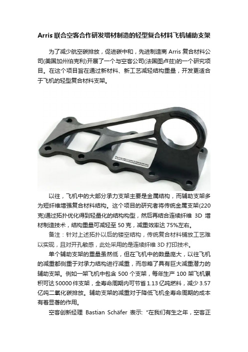
Arris联合空客合作研发增材制造的轻型复合材料飞机辅助支架为了减少航空碳排放,促进碳中和,先进制造商Arris复合材料公司(美国加州伯克利)开展了一个与空客公司(法国图卢兹)的一个研究项目。
在这个项目旨在通过新材料、新工艺减轻结构重量,开发更适合于飞机的轻型复合材料支架。
以往,飞机中的大部分承力支架主要是金属结构,而辅助支架多为短纤维增强复合材料结构。
这个项目的研究者将传统金属支架(220克)通过拓扑优化得到轻量化的结构构型,然后再结合连续纤维3D增材制造技术,结构重量可减轻至50克,减重效率达75%左右。
备注:针对上述拓扑以后的镂空结构,传统复合材料铺放工艺难以实现,且对开孔敏感,此处采用的是连续纤维3D打印技术。
单个辅助支架的重量虽然低,但在飞机中的数量庞大,以往飞机的减重都侧重于对承力结构进行减重,而忽略了具有巨大减重潜力的辅助支架。
例如一架飞机中包含500个支架,每年生产100架飞机累积可达50000件支架,全寿命周期内可节省1.13亿吨燃料,减少3.57亿吨二氧化碳排放。
辅助支架的减重对于降低飞机全寿命周期的成本有着显著的作用。
空客创新经理Bastian Schäfer表示:“在我们有生之年,空客正在朝着更清洁、更可持续的空中旅行方向发展,要实现这一改变,需要探索具有重大影响和实际应用的颠覆性想法”。
“我们设计和制造飞机的方式正在改变,因为像Arris这样的新兴科技公司实现了我们对更好的空中旅行的愿景。
我们知道仿生学、拓扑优化和先进复合材料是未来的趋势,而Arris正在帮助我们将这些设计和材料的理想结合起来,以制造未来的飞行器”。
此外,Arris增材制造技术还结合了传统增材制造(AM)和快速模压成型工艺,此项技术或可对支架等替代结构及未来的飞机结构产生重大影响,促进碳中和。
空客本身也致力于探索此类技术途径,以支持其未来可持续的发展愿景。
“批量生产”一直是工业界对于复合材料制造的一个迫切需求。
- 1、下载文档前请自行甄别文档内容的完整性,平台不提供额外的编辑、内容补充、找答案等附加服务。
- 2、"仅部分预览"的文档,不可在线预览部分如存在完整性等问题,可反馈申请退款(可完整预览的文档不适用该条件!)。
- 3、如文档侵犯您的权益,请联系客服反馈,我们会尽快为您处理(人工客服工作时间:9:00-18:30)。
ISO/TR 1151. Flight dynamics - Concepts, quantities and Symbols -Part 14:
Rotorcrafts: Classification, Geometry and Dynamic characteristics
Foreword
ISO (the International Organization for Standardization) is a worldwide federation ofnational standards bodies (ISO member bodies). The work of preparing InternationalStandards is normally carried out through ISO technical committees. Eachmemberbody interested in a subject for which a technical committee has been established hasthe right to be represented on that committee. International organizations, governmentaland non-governmental, in Iiaison with ISO, also take part in the work.
Draft International Standards adopted by the technical committees are circulated tothe member bodies for approval before their acceptance as International Standards bythe ISO Council. They are approved in accordance with ISO procedures requiring atleast 75 % approval by the member bodies voting.
International Standard ISO 1151-14 was prepared by Technical Committee ISO/TC 20,Aircraft and space vehicles.
This is the first edition
Users should note that all International Standards undergo revision from time to timeand that any reference made herein to any other International Standard implies itslatest edition, unless otherwise stated.
ISO 1151, Flight dynamics - Concepts, quantities and Symbols, comprises, atpresent, ninecompletedParts:
Part I: Aircraft motion relative to the air.
Part 2: Motions of the aircraft and the atmosphere relative to the Earth.
Part 3: Derivatives of forces, moments and their coefficients.
Part 4: Parameters used in the study of aircraft stability and control.
Part 5: Quantities used in measurements.
Part 6: Aircraft geometry.
Part 7: Flight Points and flight envelopes.
Part 8: Concepts and quantities used in the study of the dynamic behavior of the aircraft
Part 9: Model of atmospheric motions along the trajectory of the aircraft
Part 10: Physical Flight Conditions (under development)
Part 11: Control system: classification, terminology, notions and definitions (under development) Part 12: Unmanned aircraft systems (to be developed)
Part 13: Training devices (to be developed)
In all the Parts comprising ISO 1151, the term “aircraft” denotes a vehicle intended for atmosphere or space flight.
Contents
This part of ISO 1151 gives basic definitions and deals with Rotorcrafts Classification, Geometry and Dynamic characteristics.
1.
1.
1.
Lock’s inertia number represents the ratio of the aerodynamic and inertial forces on the aerodynamic and inertial forces acting on an articulated rotor blade
Where a0 – derivative of aerodynamics load factor of blade with respect to angle of attack。