BTP-6200I用户手册_V1.5
爱普生EPSON EPL-6200 installation manual说明书
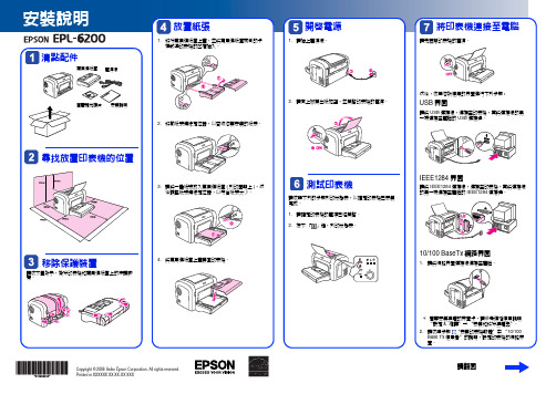
安裝說明放置紙張開啟電源將印表機連接至電腦Array請翻面Copyright © 2006 Seiko Epson Corporation. All rights reserved.Printed in XXXXXX XX.XX-XX XXX安裝印表機軟體Windows使用者1.請確定已關閉印表機的電源。
2.將印表機百寶箱光碟片放入光碟機中。
3.出現此畫面時,請按下『繼續』鍵。
4.請按下『接受』鍵。
5.出現此對話框時,請按下『安裝』鍵開始安裝。
6.請依照螢幕上的指示完成安裝。
Mac OS使用者1.請確定已關閉印表機的電源。
2.將印表機百寶箱光碟片放入光碟機中。
3.Mac OS 8/9 使用者,請雙擊〝EPSON〞圖示,然後再雙擊〝Mac OS 8/9〞圖示Mac OS X使用者,請雙擊〝EPSON〞圖示,然後再雙擊〝Mac OS X〞圖示。
請按下『接受』鍵。
出現此對話框時,請按下『安裝』鍵開始安裝。
請依照螢幕上的指示完成安裝。
10/100 BaseTX使用者EPL-6200不支援EpsonNet EasyInstall。
若要在網路界面上使用印表機,請依照下列的步驟操作:使用印表機百寶箱光碟片安裝印表機驅動程式。
Network Utilities光碟片中的EpsonNet Config來設定印表機的網路界面。
若您是使用Windows95、98或MeNetwork Utilities光碟片中安裝EpsonNet Print)新增一個Standard TCP/IP Port。
若您是使用Windows95、98或MeEpsonNet Print新增一個Standard TCP/IP Port)詳細步驟,請參考Network Utilities。
BT系列手持式抄表软件操作手册
目录第一章 BT系列抄表机简介 3 1.1概述 (3)1.2性能表 (4)第二章 BT系列手持式抄表终端深入使用 5 2.1快捷热键的定义 (5)2.2开机操作 (8)2.2.1密码验证 (8)2.3抄表 (10)2.3.1进入抄表流程 (10)2.3.2录入示数 (11)2.3.3录入异常状态码 (13)2.4分时电表的抄收 (15)2.4.1进入抄表流程 (15)2.4.2红外抄表 (16)2.4.4分时电表的集中抄收 (17)2.5功能菜单 (17)2.5.1抄表户定位(条件定位) (17)2.5.2其它定位方式 (18)2.5.3查询状态图 (19)2.5.4统计信息 (20)2.5.5密码保护 (20)2.5.6帮助(操作提示) (21)2.6补抄 (21)2.7上下装 (22)2.8设置参数 (22)2.8.1环宇补位 (23)2.8.2突变范围 (24)2.8.3运行选项 (24)2.8.4通讯配置 (26)2.8.5版本(设置运行的主台系统版本) (26)2.9退出 (27)第三章居民分时电表抄收基本步骤 28 3.1开机 (28)3.2进入执行程序 (28)3.3进入抄表主菜单 (29)3.4进入抄表界面 (29)3.5普通居民电表抄收 (30)3.6居民分时电表抄收 (30)3.7居民分时电表集中抄收 (31)第四章多功能电表抄收 32 4.1抄分时表 (32)4.2抄GB645表 (33)4.3抄兰吉尔表 (34)4.4抄ABB表 (35)4.5抄威胜企标表 (35)第五章上下装(主台) 37 5.1上下装(苏源主台系统) (37)5.1.1数据下装 (37)5.1.2数据下装(抄表机操作) (41)5.1.3数据上装 (41)5.1.4数据上装(抄表机操作) (42)5.2上下装(环宇主台系统) (42)5.2.1下装数据 (42)5.2.2上装数据 (45)5.2.3抄表机操作 (45)第六章下装抄表应用软件 46 6.1下装条件 (46)6.2下装步骤 (46)第七章维护、保养和环保 49附录 (50)第一章 BT系列抄表机简介1.1 概述BT系列手持式抄表终端主要适用于在各种流动性强的工作领域中进行数据采集和现场数据分析处理的工作。
北洋打印机BTP-6200I,6300I 用户手册V1.7

目录1概述 (4)1.1简介 (4)1.2主要特点 (4)2主要技术指标 (5)2.1主要技术规格 (5)2.2打印介质技术指标 (6)2.2.1纸张技术指标 (6)2.2.2碳带技术指标 (6)2.3打印及出纸位置 (7)3外观和组件 (8)3.1外观和组件 (8)3.2主要组件介绍 (9)3.3指示灯、按键、液晶功能说明 (9)3.3.1指示灯功能说明 (9)3.3.2按键功能说明 (10)3.3.3液晶功能说明 (11)3.4告警指示灯和蜂鸣器 (12)3.5按键配置功能说明 (13)4通讯接口 (14)4.1串行接口 (14)4.1.1接口信号 (14)4.1.2接线示意图 (14)4.2并行接口 (15)4.3USB接口 (15)4.4以太网接口 (16)5打印机的安装 (17)5.1开箱检查 (17)5.2打印机安装位置 (17)5.3连接电源 (17)5.4连接接口电缆 (18)5.5安装纸卷 (18)5.6安装碳带 (20)5.7启动打印机 (21)5.7.1开机与自检 (21)5.7.2打印自检样张 (21)5.7.3设置纸张类型 (21)5.7.4校验标记 (22)6打印机调节 (24)6.1打印头压力调节 (24)6.2打印头位置调节 (25)6.3传感器位置调节 (26)6.3.1反射传感器调整 (26)6.3.2透射传感器调整 (26)6.4打印机常用参数调整 (27)6.4.1打印机常用参数的调整及调整范围 (27)6.4.2票面上打印内容位置坐标及调整方向 (27)7打印机的日常维护 (30)7.1打印头清洁 (30)7.2传感器清洁 (30)7.3打印胶辊清洁 (31)8故障处理方法与维护 (32)8.1液晶错误信息显示 (32)8.2打印质量问题 (33)附录 (34)附录1自检样张 (34)附录2纸张的技术规格 (37)声明本手册内容未经同意不得随意更改,山东新北洋信息技术股份有限公司(以下简称新北洋)保留在技术、零部件、软件和硬件上变更产品的权利。
RVB-6200说明书
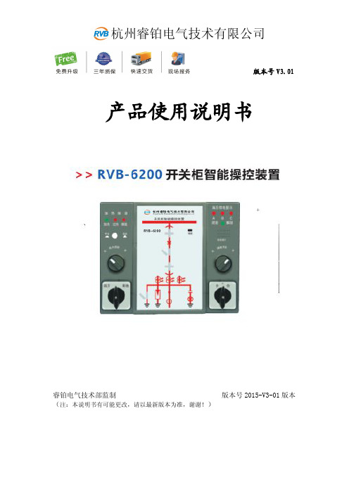
杭州睿铂电气技术有限公司
4) LED 灯显示区 当有风机工作时,风机指示灯亮,当有加热器工作时,加热指示灯亮, 当有负载故障时,断线指示灯亮。
3. 智能语音防误功能
手车柜: 当断路器处于工作位置和试验位置时,红色发光条 3(1)、3(2)和绿色发光条 4(1)、
4(2)同时闪烁;如果此时接地开关被强行合闸,则红色垂直模拟发光条 5 发光,而分 闸绿色发光条 6 闪烁,并且有“请分接地开关的”语音提示,待操作者分闸操作后停止。 此功能是用来防止操作者误合接地开关。 当断路器处于工作位置时,红色发光条 3(1)、3(2)发光如果此时 接地开关被强行合闸,则红色垂直模拟发光条 05 发光,而分闸绿色 发光条 6 闪烁,并且有“请分接地开关”的语音提示,待操作者分闸操作后停止。此功能 是用来防止操作者误合接地开关。 当以上情况同时发生时,则发光条 2 和发光条 6 同时闪烁,并且有“请分断路器,请分 接地开关”的语音提示。 固定柜: 当上隔离刀、断路器、接地开关同时闭合时,红色发光条 1、5 发光和绿色发光条 2、6 同时闪烁,并且有“请分断路器,请分接地开关”的语音提示。 当上隔离刀或下隔离刀、接地开关同时闭合时,红色发光条 3(1)或 3(2)发光,红色 发光条 5 发光,绿色发光条 6 闪烁,并且有“请分接地开关”的语音提示。
2
一、概述
杭州睿铂电气技术有限公司
RVB-6200 开关柜智能操控装置是我公司针对电力开关柜研制开发的一款新型多功能、模拟动态指示的智能 装置。本产品适用于中置柜、手车柜、固定柜、环网柜等多种开关柜。装置本身具有动态一次模拟图,带 电显示及闭锁、温湿度智能控制、断路器分合状态指示、储能指示、接地开关状态指示、手车位置指示、 分合闸回路完好指示、语音防止误操作提示、远方/就地操作、远程通信、柜内照明等功能。
otp6200测试仪表使用说明
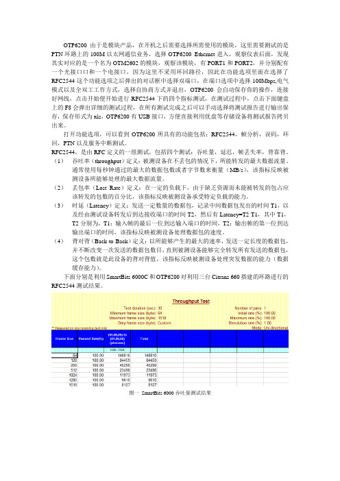
OTP6200由于是模块产品,在开机之后需要选择所需使用的模块,这里需要测试的是PTN环路上的100M以太网通信业务,选择OTP6200_Ethernet进入,观察仪表后面,发现其实对应的是一个名为OTM2602的模块,观察该模块,有PORT1和PORT2,并分别配有一个光接口口和一个电接口,因为这里不采用环回路径,因此在功能选项里面在选择了RFC2544这个功能选项之后弹出的对话框中选择双端口,在端口选项中选择100Mbps,电气模式以及全双工工作方式,选择自协商方式并退出,OTP6200会自动保存你的操作,连接好网线,点击开始便开始进行RFC2544下的四个指标测试,在测试过程中,点击下面键盘上的F8会弹出详细的测试过程,在所有测试完成之后可以手动选择将测试报告进行输出保存,保存形式为xls,OTP6200有USB接口,方便直接利用优盘等存储设备将测试报告拷贝出来。
打开功能选项,可以看到OTP6200所具有的功能包括:RFC2544,帧分析,误码,环回,PTN以及服务中断测试。
RFC2544,是由RFC定义的一组测试,包括四个测试:吞吐量,延迟,帧丢失率,背靠背。
(1)吞吐率(throughput)定义:被测设备在不丢包的情况下,所能转发的最大数据流量。
通常使用每秒钟通过的最大的数据包数或者字节数来衡量(MB/s),该指标反映被测设备所能够处理的最大数据流量。
(2)丢包率(Lost Rate)定义:在一定的负载下,由于缺乏资源而未能被转发的包占应该转发的包数的百分比,该指标反映被测设备承受特定负载的能力。
(3)时延(Latency)定义:发送一定数量的数据包,记录中间数据包发出的时间T1,以及经由测试设备转发后到达接收端口的时间T2,然后有Latency=T2-T1,其中T1,T2分别为,T1:输入帧的最后一位到达输入端口的时间,T2:输出帧的第一位到达输出端口的时间,该指标反映被测设备处理数据包的速度。
OTP6200用户手册V1.00

5.2 安装或升级应用程序................................................................................. 9 5.3 插入或取出测试模块...............................................................................10
6 设置设备..........................................................................................14
6.1 重新校准触摸屏.......................................................................................14 6.2 调整音量.................................................................................................. 14 6.3 设置日期和时间格式...............................................................................15 6.4 选择操作语言...........................................................................................17 6.5 调整背光.................................................................................................. 18 6.6 软件自恢复.............................................................................................. 18 6.7 远程控制.................................................................................................. 19 6.8 设置 IP 地址.............................................................................................20 6.9 PING 测试.................................................................................................21
plantronics voyager 6200 uc 用户指南说明书

Voyager 6200 UC 用户指南内容耳机概述3请注意安全3连接和配对4连接至 PC4配置媒体4配对至移动设备4USB 蓝牙适配器5再次配对 USB 适配器5加载软件6充电7检查耳机电池状态7配戴调整8更换耳塞8基础知识9电源开/关9调整音量9播放或暂停音频9曲目选择9快进/快退9语音控制9拨打/接听/结束通话9更多功能11选择语言11降噪11在线指示灯11更改耳机设置12重新调整耳机声音12主叫方播报(仅限手机)12更新固件13耳机恢复13故障诊断14支持15LED静音ANC主动降噪电源播放/暂停*下一首曲目*上一首曲目*蓝牙® 配对音量呼叫语音控制:Siri、Google Now™、Cortana注*功能因应用程序而异。
可能不支持运行基于网络的应用程序。
使用新耳机前,请阅读关于安全、充电、电池和管制等重要信息的安全指南。
耳机概述请注意安全您的蓝牙 USB 适配器和您的耳机已预先配对。
1打开耳机,并将蓝牙 USB 适配器插入您的笔记本电脑或 PC。
2USB 适配器 LED 将闪烁蓝色,然后一直呈蓝色亮灯,表示耳机已连接至 USB 适配器。
如果您正佩戴耳机,则会听到“PC 已连接”,表示已建立连接。
通话时,USB 适配器上的LED 会闪烁蓝色。
未通话时,LED 呈稳定蓝色。
3可选项 可通过访问 /software 加载 Windows 和 Mac 适用的 Plantronics Hub 。
这将使您能够通过高级设置和选项自定义耳机状态。
您的 USB 蓝牙适配器已经准备好接听电话,但听音乐占用了一些额外配置。
Windows 1要配置蓝牙 USB 适配器以便播放音乐,请转至“开始”菜单 > 控制面板 > 声音 > “播放”选项卡。
选择 Plantronics BT600,将其设置为默认设备,然后单击“确定”。
2要在拨打电话或接听电话期间暂停音乐,请转至“开始”菜单 > 控制面板 > 声音 > “通信”选项卡,然后选择所需的参数。
DNB6200初始数据配置(LMT)
Page12
配置时钟源
设臵参考时钟源工作模式 ( SET CLKMODE )
设臵参考时钟源工作模式
手动模式表示用户手动指定某一路参考时钟源 自动模式表示系统根据参考时钟源的优先级和可用状态自动选择 参考时钟源 自振模式表示系统工作于自由振荡状态,不跟踪任何参考时钟源
。
Copyright © 2010 Huawei Technologies Co., Ltd. All rights reserved.
Copyright © 2010 Huawei Technologies Co., Ltd. All rights reserved.
Page20
增加物理层数据
设臵E1/T1端口 ( SET E1T1)
设臵E1/T1端口属性
Copyright © 2010 Huawei Technologies Co., Ltd. All rights reserved.
一条SAAL链路只能承载一个IUBCP端口
至少添加3条SAAL链路
Copyright © 2010 Huawei Technologies Co., Ltd. All rights reserved.
Page23
增加控制面数据
增加Iub控制端口 ( ADD IUBCP)
增加由SAAL 链路承载的NCP和CCP
7号槽位系统默认识别
Copyright © 2010 Huawei Technologies Co., Ltd. All rights reserved.
Page8
增加天线
增加天线 ( ADD ANTENNA )
IWPTL系列产品操作指南说明书

|IWPTL SeriesINDUSTRIAL WIRELESS PRESSURE TRANSMITTERWhilst every effort has been taken to ensure the accuracy of this document, we accept no responsibility for damage, injury, loss, or expense resulting from errors or omissions, and reserve the right of amendment without notice.Information for usersThis equipment has been tested and found to comply with the limits for a Class B device, pursuant to part 15 of the FCC Rules. These limits are designed to provide reasonable protection against harmful interference in a residential installation. This equipment generates uses and can radiate radio frequency energy, and if not installed and used in accordance with the instructions, may cause harmful interference to radio communications. However, there is no guarantee that interference will not occur in a particular installation. If this equipment does cause harmful interference to radio or television reception, which can be determined by turning the equipment off and on, the user is encouraged to try to correct the interference by one or more of the following measures:•Reorient or relocate the receiving antenna•Increase the separation between the equipment and receiver•Connect the equipment into an outlet on a circuit different from that which the receiver is connected•Consult the dealer or an experienced radio/TV technician for helpCaution: To satisfy FCC RF Exposure requirements for mobile and base station transmission devices, a separation distance of 20cm or more should be maintained between the antenna of this device and persons during operation. To ensure compliance operation at closer than this distance is not recommended. The antenna used for this transmitter must not be co-located or operating in conjunction with any other antenna or transmitter. No other antenna may be used with this equipment other than the PCB antenna supplied with this equipment.This document may not be reproduced in any way without the prior written permission of the company.Cynergy3 Components Ltd7 Cobham Road, Ferndown Industrial Estate, WimborneDorset BH21 7PE, United KingdomTel:+44(0)1202897969,email:******************CONTENTS1.INTRODUCTION _______________________________________________________ 21.1 SAFETY INFORMATION _____________________________________________________ 21.2HARDWARE FEATURES ____________________________________________________ 22.UNPACKING__________________________________________________________ 33.PRODUCT IDENTIFICATION LABEL _____________________________________ 35.SETTING UP THE IWPT WIRELESS PRESSURE TRANSMITTER ___________ 46.TROUBLE-SHOOTING GUIDE__________________________________________ 67.SYSTEM PART NUMBERS______________________________________________ 78.SPECIFICATIONS & CERTIFICATIONS__________________________________ 9 1. INTRODUCTION1.1 Safety InformationThis manual contains information that must be observed in the interest of your safety and to avoid damage to assets. Please read this manual before installing and commissioning the device and keep the manual in an accessible location for all users.Contains FCC ID: W70MRF24J40MDMECaution: To satisfy FCC RF Exposure requirements for mobile and base station transmission devices, a separation distance of 20cm or more should be maintained between the antenna of this device and persons during operation. To ensure compliance operation at closer than this distance is not recommended. The antenna used for this transmitter must not be co-located or operating in conjunction with any other antenna or transmitter. No other antenna may be used with this equipment other than the PCB antenna supplied with this equipment.Please see the Certifications section for more information on RF Exposure Compliance 1.2 Hardware FeaturesThe IWPTL range of Wireless Pressure Transmitters has been designed to measure the pressure of the medium connected and transmit the value to one of the IWR range of receivers where the value can be outputted as either a 4-20 mA or 1-5 V dc signal.The IWR-1 has a single output and the IWR-5 has five outputs, each of which can be linked to an IWPT transmitter. The IWPT pressure transmitter works on the license-free 2.4 GHz band.Ranges of up to 500 m are possible using the standard transmitter and receiver unit with the optional 3dBi antenna giving a range of up to 750 m. The transmitter is powered by a 3.6V lithium cell and care must be taken to insert the battery in the correct polarity.2. UNPACKINGThe instrument should be carefully inspected for signs of damage that may have occurred in transit. In the unlikely case that damage has been sustained, DO NOT use the instrument, but please retain all packaging for our inspection and contact your supplier immediately.3. PRODUCT IDENTIFICATION LABELThe unit delivered should be carefully inspected to ensure it is suitable for the application required. Detailed information on the product is included in the identification label and the user manual.Please ensure in particular, that the pressure range of the IWPTL is suitable for the intended application and that the IWPT unit will not be subjected to pressures and/or temperatures greater than those specified in this manual.4. INSTALLING/CHANGING THE BATTERYA Lithium 3.6V battery is included inside the IWPTL transmitter. The battery may be changed at any time but the correct polarity must be observed at all times! After the battery has been changed, the pushbutton SW1 should be pushed for 5s at the same time as the unit is switched on using SW3. This is to ensure the battery life count is set correctly when a new battery is installed.The internal LED will flash 5 times to indicate this procedure has been carried out successfully.The battery life is determined by the rate the transmitter sends the Pressure value to the receiver, this update rate can be selected using Dip Switch 1 and the default value is 10s. Please dispose of all batteries as specified by the legislator according to the Closed Substance Cycle and Waste Management Act or country regulations.! ! WARNING !MAKE SURE THE CORRECT BATTERY POLARITY IS OBSERVED!!! WARNING !INCORRECT BATTERIES MAY DAMAGE THE UNIT USE ONLY 3.6V LITHIUM C CELL BATTERIES5.1 Mounting InstructionsEnsure that:-- The instrument is used on a pressure medium that is compatible with the wetted parts- The correct seal is used and that the maximum torque (see below) is not exceeded- Fluid is not allowed to freeze in the pressure port as the diaphragm may be ruptured- No sharp objects are inserted into the pressure port as the diaphragm may be damagedTighten the unit in place using a wrench on the 18mm A/F hexagon provided on the unit. Ensure that no more than 15Nm is applied, that the system is de-pressurized, and that a suitable pressure seal is used.5.2 SETTING UP THE IWPTL WIRELESS PRESSURE TRANSMITTERThe IWPTL instrument is shipped in a default configuration which allows the unit to connect with any default IWR receiver unit and transmit the measured pressure every 10s simply by switching the unit on using SW3 on the internal circuit board.If a different update rate is required, or a different network frequency channel is required these parameters can be selected using DIP Switch 1 as detailed below:Switches 1, 2, 3 & 4 select the RF Network the IWPTL will transmit on. The default network for both the IWPT transmitter and IWR receiver is network 1. RF NETWORK 1 2 3 4 1 0 0 0 0 2 0 0 0 1 3 0 0 1 0 4 0 0 1 1 5 0 1 0 0 6 0 1 0 1 7 0 1 1 0 8 0 1 1 1DIP SWITCHLED1BATTERYON/OFF Switch SW3SW1USB+9 1 0 0 010 1 0 0 111 1 0 1 012 1 0 1 113 1 1 0 014 1 1 0 115 1 1 1 016 1 1 1 1Switches 5, 6 & 7 select the Transmission rate of the unit. This effectively sets how often the pressure value is sent to the receiver.Transmit time 5 6 710 seconds 0 0 020 seconds 0 0 130 seconds 0 1 060 seconds 0 1 1120 seconds 1 0 0600 seconds 1 0 11 second 1 1 05 seconds 1 1 1Switches 8, 9, and 10 set the Channel Number of the transmitter. This is used with the 5 channel receiver unit (IWR-5) to select which Pressure transmitter is linked to which4-20 mA or 1-5 V dc output channel.Tx Channel Number 8 9 101 0 0 02 0 0 13 0 1 04 0 1 15 1 0 0The IWPTL transmitter is now set up and ready to be used. Install the unit into the pipework as required and switch the unit ON using SW3. Pushbutton switch SW1 can be pushed to force the unit to transmit its current pressure and LED 1 will flash twice if the transmission has been received and acknowledged by an IWR receiver unit.If the unit has transmitted successfully the 4-20 mA or 1-5 V dc output of the connected receiver unit will output a value reflecting the pressure level being measured.6.TROUBLE-SHOOTING GUIDEProblem encountered Possible CausesLED1 doesn’t flash when push button SW1 is pressed Unit not switched on, switch on using SW3. The battery is not installed correctly.The battery needs replacing.LED1 only flashes once when SW1 is pressed IWR receiver not switched on. IWR receiver is not set up for the same RFnetwork.IWR receiver not within range of the transmitter.If an IWR-1 receiver is used, ensure that the transmitter is set to Tx Channel 1Output from the IWR receiver isn’t equivalent to the Pressure being monitored IWR receiver set up incorrectly, see IWR user manual for further details.Check that the green external LED on the receiver is flashing when the transmitter push button is pressed as the receiver may be out of range.7. SYSTEM PART NUMBERSPart Number Pressure Range Receiver Output IWPT-G1000-00 0-1 Bar g 4-20 mA or 1-5 V dc IWPT-G6000-00 0-6 Bar g 4-20 mA or 1-5 V dc IWPT-GM1P9-00 -1-+9 Bar g 4-20 mA or 1-5 V dc IWPT-G1002-00 0-10 Bar g 4-20 mA or 1-5 V dc IWPT-G1602-00 0-16 Bar g 4-20 mA or 1-5 V dc IWPT-CO184-00 -1-+24 Bar g 4-20 mA or 1-5 V dc IWPT-G2502-00 0-25 Bar g 4-20 mA or 1-5 V dc IWPT-G4002-00 0-40 Bar g 4-20 mA or 1-5 V dc IWPT-G1003-00 0-100 Bar g 4-20 mA or 1-5 V dc IWPT-G2503-00 0-250 Bar g 4-20 mA or 1-5 V dc IWPT-G4003-00 0-400 Bar g 4-20 mA or 1-5 V dc IWPTU-GP015-00 0-15 psi g 4-20 mA or 1-5 V dc IWPTU-GP030-00 0-30 psi g4-20 mA or 1-5 V dc IWPTU-CO446-00 -14.5 to +150 psi g4-20 mA or 1-5 V dc IWPTU-GP075-00 0-75 psi g4-20 mA or 1-5 V dc IWPTU-GP100-00 0-100 psi g4-20 mA or 1-5 V dc IWPTU-CO447-00 -14.5 to +350 psi g4-20 mA or 1-5 V dc IWPTU-GP150-00 0-150 psi g4-20 mA or 1-5 V dc IWPTU-GP300-00 0-300 psi g4-20 mA or 1-5 V dc IWPTU-GP750-00 0-750 psi g4-20 mA or 1-5 V dc IWPTU-GP1K5-00 0-1500 psi g4-20 mA or 1-5 V dc IWPTU-GP3K6-00 0-3600 psi g4-20 mA or 1-5 V dc IWPTU-GP5K8-00 0-5800 psi g4-20 mA or 1-5 V dc IWPTL-G0050-00 0-50 mbar g 4-20 mA or 1-5 V dc IWPTL-G0100-00 0-100 mbar g 4-20 mA or 1-5 V dc IWPTL-G0250-00 0-250 mbar g 4-20 mA or 1-5 V dc IWPTL-G0500-00 0-500 mbar g 4-20 mA or 1-5 V dc IWPTL-G0750-00 0-750 mbar g 4-20 mA or 1-5 V dc IWPTL-G1000-00 0-1000 mbar g 4-20 mA or 1-5 V dc IWPTL-A0500-00 0-500 mbar abs 4-20 mA or 1-5 V dc IWPTL-A0750-00 0-750 mbar abs 4-20 mA or 1-5 V dc IWPTL-A1000-00 0-1000 mbar abs 4-20 mA or 1-5 V dcPart Number Pressure Range Receiver Output IWPTLU-GP001-00 0-1 psi g 4-20 mA or 1-5 V dc IWPTLU-GP002-00 0-2 psi g 4-20 mA or 1-5 V dc IWPTLU-GP005-00 0-5 psi g 4-20 mA or 1-5 V dc IWPTLU-GP008-00 0-8 psi g 4-20 mA or 1-5 V dc IWPTLU-GP010-00 0-10 psi g 4-20 mA or 1-5 V dc IWPTLU-GP015-00 0-15 psi g 4-20 mA or 1-5 V dc IWPTLU-AP005-00 0-5 psi abs 4-20 mA or 1-5 V dc IWPTLU-AP010-00 0-10 psi g 4-20 mA or 1-5 V dc IWPTLU-AP015-00 0-15 psi g 4-20 mA or 1-5 V dcPart Number Number of Output ChannelsIWR-1 OneIWR-5 FiveIANT-3 3 dBi Antenna IWPT-SA Swivel Adaptor (1/4” BSP)8.SPECIFICATIONS & CERTIFICATIONSUnited States FCCThis equipment has been tested and found to comply with the limits for a Class B device, pursuant to part 15 of the FCC Rules. These limits are designed to provide reasonable protection against harmful interference in a residential installation. This equipment generates, uses, and can radiate radio frequency energy, and if not installed and used in accordance with the instructions, may cause harmful interference to radio communications. However, there is no guarantee that interference will not occur in a particular installation. If this equipment does cause harmful interference to radio or television reception, which can be determined by turning the equipment off and on, the user is encouraged to try to correct the interference by one or more of the following measures:• Reorient or relocate the receiving antenna• Increase the separation between the equipment and receiver• Connect the equipment into an outlet on a circuit different from that which the receiver is connected • Consult the dealer or an experienced radio/TV technician for helpWarning: Changes or modifications not expressly approved by Cynergy3 could void the user’s authority to operate the equipment.RF ExposureContains FCC ID: W70MRF24J40MDMEIn this equipment, the antenna supplied is a PCB antenna and an alternative antenna must not be used.System PerformanceAccuracy (non-linearity & hysteresis <±0.25% / FS (BFSL)Setting ErrorsZero & Full Scale,<±0.5% / FS Thermal Zero Shift <±0.04% / FS / °C Thermal Span Shift <±0.02% / °C typicalMedia Temperature -20 to +135 °C Ambient Temperature -20 to +50 °C Storage Temperature -20 to +80 °CPressure Housing 303 Stainless Steel O Ring Seals Viton DiaphragmCeramic Enclosure Material Acetal Weight310 gRF TransmitterContains FCC W70MRF24J40MDME Power Requirements Lithium Ion C 3.6V CellBattery Life 5 Years (10s transmission rate)Dimensions 132mm x 79mm x 52mm (L x W x D) Mounting Any OrientationSensata Technologies, Inc. (“Sensata”) data sheets are solely intended to assist designers (“Buyers”) who are developing systems that incorporate Sensata products (also referred to herein as “components”). Buyer understands and agrees that Buyer remains responsible for using its independent analysis, evaluation and judgment in designing Buyer’s systems and products. Sensata data sheets have been created using standard laboratory conditions and engineering practices. Sensata has not conducted any testing other than that specifically described in the published documentation for a particular data sheet. Sensata may make corrections, enhancements, improvements and other changes to its data sheets or components without notice.Buyers are authorized to use Sensata data sheets with the Sensata component(s) identified in each particular data sheet. HOWEVER, NO OTHER LICENSE, EXPRESS OR IMPLIED, BY ESTOPPEL OR OTHERWISE TO ANY OTHER SENSATA INTELLECTUAL PROPERTY RIGHT, AND NO LICENSE TO ANY THIRD PARTY TECHNOLOGY OR INTELLECTUAL PROPERTY RIGHT, IS GRANTED HEREIN. SENSATA DATA SHEETS ARE PROVIDED “AS IS”. SENSATA MAKES NO WARRANTIES OR REPRESENTATIONS WITH REGARD TO THE DATA SHEETS OR USE OF THE DATA SHEETS, EXPRESS, IMPLIED OR STATUTORY, INCLUDING ACCURACY OR COMPLETENESS. SENSATA DISCLAIMS ANY WARRANTY OF TITLE AND ANY IMPLIED WARRANTIES OF MERCHANTABILITY, FITNESS FOR A PARTICULAR PURPOSE, QUIET ENJOYMENT, QUIET POSSESSION, AND NON-INFRINGEMENT OF ANY THIRD PARTY INTELLECTUAL PROPERTY RIGHTS WITH REGARDTO SENSATA DATA SHEETS OR USE THEREOF.All products are sold subject to Sensata’s terms and conditions of sale supplied at SENSATA ASSUMES NO LIABILITY FOR APPLICATIONS ASSISTANCE OR THE DESIGN OF BUYERS’ PRODUCTS. BUYER ACKNOWLEDGES AND AGREES THAT IT IS SOLELY RESPONSIBLE FOR COMPLIANCE WITH ALL LEGAL, REGULATORY AND SAFETY-RELATED REQUIREMENTS CONCERNING ITS PRODUCTS, AND ANY USE OF SENSATA COMPONENTS IN ITS APPLICATIONS, NOTWITHSTANDING ANY APPLICATIONS-RELATED INFORMATION OR CONTACT US EUROPE+44 (0)1202 897969********************* Cynergy3 Components Ltd.7 Cobham Road, Ferndown Industrial Estate, Wimborne, Dorset,BH21 7PE, United Kingdom USACaution: To satisfy FCC RF Exposure requirements for mobile and base station transmission devices, a separation distance of 20cm or more should be maintained between the antenna of this device and persons during operation. To ensure compliance operation at closer than this distance is not recommended. The antenna used for this transmitter must not be co-located or operating in conjunction with any other antenna or transmitter. No other antenna may be used with this equipment other than the PCB antenna supplied with this equipment.Canada (IC)EnglishThis device complies with Industry Canada license-exempt RSS standard(s). Operation is subject to the following two conditions: (1) this device may not cause interference, and (2) this device must accept any interference, including interference that may cause undesired operation of the device.Under Industry Canada regulations, this radio transmitter may only operate using an antenna of the type and maximum (or lesser) gain approved for the transmitter by Industry Canada. To reduce potential radio interference to other users, the antenna type and its gain should be so chosen that the equivalent isotropically radiated power (e.i.r.p.) is not more than that necessary for successful communication. FrenchLe présent appareil est conforme aux CNR d’industrie Canada applicables aux appareils radio exempts de licence. L’explitation est autorisée aux deux conditions suivantes: (1) l’appareil ne doit pas produire de brouillage, et (2) l’utilisateur de l’appareil doit accepter tout brouillage, et (2) l’utilisateur de l’appareil doit accepter tout brouillage radioelectrique subi, même si le brouillage est susceptible d’en compromettre le fonctionnement.Conformément à la réglementation d’Industrie Canada, le présent émetteur radio peut fonctionner avec une antenna d’un type et d’un gain maximal (ou inférieur) approuvé pour l’émetteur par Industrie Canada. Dans le but de réduire les risques de brouillage radioélectrique à I’intention des autres utilisateurs, il fait choisir le type d’antenne et son gain de sorte que la puissance isotrope rayonnée équivalente (p.i.r.e) ne dépasse pas l’intensité nécessaire à l’établissement d’une communication satisfaisante.EuropeThe MRF24J40MD/ME wireless module used in this equipment has been tested to R&TTE Directive 1995/5/EC Essential Requirements for Health and Safety (Article 3.1(a)), Electromagnetic Compatibility (EMC) Article 3.1(b)) and Radio (Article 3.2) and are summarized in the table below. A Notified Body Opinion has also been issued for this module.Certification Standards ArticleSafety EN60950-2006+A11+A1:2010 (3.1(a))Health EN50371:2002-03 (3.1(a))EMC EN301 489-1 V1..8.1 (2008-04_ (3.1(b))EMC EN301-489-17 V2.1.1(2009-05) (3.1(b))Radio EN 300 328 V1.7.1(2006-10) (3.2)。
6200面板操作指南(中文)介绍
需量*
kVA, kVAR, kW, IAVG
峰值需量(最大)* kVA, kVAR, kW, IAVG
最大/最小值
最大/最小值测量在以后的版本中会支持。
* 加*号的组显示的系统(总)值。
×1000 指示
当“×1000”的 LED 指示灯亮的时候,实际值=1000×显示值。
显示模式下的按键功能
下面表格将描述显示模式下前面板按键的功能。
前面板按键功能
深圳市中电电力技术有限公司
对于每一种模式,都会用一个表格来说明这些按键的功能。 如果在按键的后面紧跟着三个点(… ),就表示按这些按键的时候要求保持 2 秒时间。
显示模式
相量测量 该列表显示的是每一
相的测量值( A,B,C)
如果 A,B,C 下面的 LED 亮则表明测量 值为负
系统测量 该列表显示的是 系统测量值。显 示屏的每一行显 示不同的系统测 量值。
PML 6200 ION 面板操作指南
深圳市中电电力技术有限公司
PML 6200ION 面板操作指南
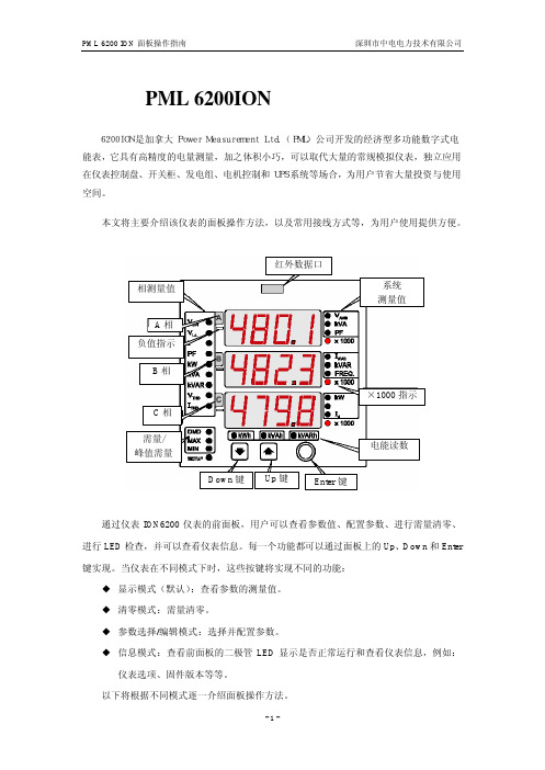
6200ION 是加拿大 Power Measurement Ltd.(PML)公司开发的经济型多功能数字式电 能表,它具有高精度的电量测量,加之体积小巧,可以取代大量的常规模拟仪表,独立应用 在仪表控制盘、开关柜、发电组、电机控制和 UPS 系统等场合,为用户节省大量投资与使用 空间。
模式
按键
功能
显示模式
(仪表默认为 显示模式。)
查看前一个参数值。 查看下一个参数值。 从一个测量组切换到下一个测量组。
查看参数测量值
ION6200 仪表默认为显示模式,并且默认显示系统测量组的参数。 下面将介绍如何在显示模式中查看测量值。
CS6200操作手册 13_维护与调试操作
维护与调试操作目录目录第1章维护和调试...............................................................................1-11.1Ping..............................................................................................................1-11.2Ping6............................................................................................................1-11.3Traceroute..................................................................................................1-11.4Traceroute6................................................................................................1-11.5Show............................................................................................................1-21.6Debug..........................................................................................................1-31.7Logging.......................................................................................................1-3第2章定时重启交换机.......................................................................2-12.1定时重启交换机简介.................................................................................2-12.2定时重启交换机任务序列.........................................................................2-1第3章CPU收发报文调试..................................................................3-13.1CPU收发报文简介.....................................................................................3-13.2CPU收发报文任务序列.............................................................................3-1第4章DCP功能调试..........................................................................4-14.1DCP功能简介.............................................................................................4-14.2DCP功能任务序列.....................................................................................4-14.3DCP功能配置举例.....................................................................................4-24.4DCP功能排错帮助.....................................................................................4-3第5章COPP功能调试.......................................................................5-15.1COPP功能简介..........................................................................................5-15.2COPP功能任务序列..................................................................................5-15.3COPP功能配置举例..................................................................................5-45.4COPP功能排错帮助..................................................................................5-5第1章维护和调试当用户配置交换机时,需要查看各项配置是否配置正确,交换机是否符合期望,工作正常;或者当网络出现了故障,用户需要诊断故障,交换机为此提供了ping、telnet、show、debug等多种调试命令,帮助用户查看系统配置、运行状态,找到故障原因。
i6200企业手机折页说明书
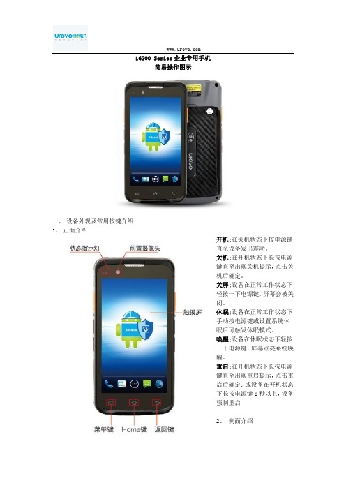
i6200 Series企业专用手机简易操作图示一、设备外观及常用按键介绍1、正面介绍开机:在关机状态下按电源键直至设备发出震动。
关机:在开机状态下长按电源键直至出现关机提示,点击关机后确定。
关屏:设备在正常工作状态下轻按一下电源键,屏幕会被关闭。
休眠:设备在正常工作状态下手动按电源键或设置系统休眠后可触发休眠模式。
唤醒:设备在休眠状态下轻按一下电源键,屏幕点亮系统唤醒。
重启:在开机状态下长按电源键直至出现重启提示,点击重启后确定;或设备在开机状态下长按电源键8秒以上,设备强制重启2、侧面介绍3、背面介绍二、锂离子充电电池客户使用、运输须知及注意事项1、客户使用须知①收到设备(含电池)后建议即刻使用,闲置时间不宜超过3个月;②不宜在温度过高或过低的环境中使用设备或对设备进行充电;③仅限使用产品标配充电器或座充对电池充电;④如果暂时不使用设备(含电池),请将电池和设备分开存放,禁止将电池装入设备内一起存放;⑤对暂时不用的电池每隔 3 个月必须进行1 次充放电操作,并补电至60%~70%电量(即3.8V~3.9V)存放;⑥锂离子电池应被储存于清凉、干燥、通风的环境中,建议在0~28℃的环境中2、运输须知①电池在环境温度高于 65℃时运输电池不可运输;②需将电池分开放置,不可将电池直接叠放在一起,避免电池与电池之间正、负极接触短路、避免造成异常事件上;③可以用包装袋、纸、泡棉等绝缘材料进行隔开即可,然后再放纸箱内,尽可能将纸箱内部塞满,避免晃动3、注意事项1、禁止把电池丢入火中,或者暴露在产生热源的地方;2、禁止把电池的正、负极反接、短路;3、禁止冲击或者震动电池;4、禁止把电池浸入水中或者使电池受潮;5、禁止把不同型号和不同生产厂商的电池混合在一起使用;6、禁止使用被改装过的或者损坏的充电器;7、禁止使用不符合厂家指定要求的充电器;8、禁止使用超出电池规格书指定的规格放电;9、禁止在强静场和强磁场的地方使用电池,否则易破坏电池安全保护装置,带来安全隐患;10、电池组合外包装膜易被镍片、尖针等尖锐部件损伤,禁止用尖锐部件碰伤电池;11、如果电池在使用或储存中发出异味、发热、变色、变形,或是在充电过程中出现任何异常现象,立即将电池从充电器或装置中移开,并停止使用;12、如果发现电池漏液或者有异味(电解液)请立即报废该电池,如电解液进入眼睛,请不要揉擦,应用清水清洗眼睛,并立即送医院治疗,否则会伤害眼睛;13、电池属于损耗品,会随着使用循环的增多其容量也会逐渐降低,建议1-2年更换新电池;14、若使用电池时发生意外,请保护现场、保留拍照等证据,及时联系我司售后处理。
用户手册

BK-W056热敏打印机(原型号:BT-W05624CKP)用户手册山东新北洋信息技术股份有限公司声明本手册内容未经同意不得随意更改,山东新北洋信息技术股份有限公司(以下简称新北洋)保留在技术、零部件、软件和硬件上改善产品的权利。
用户如果需要与产品有关的进一步信息,可以与新北洋或经销商联系。
本手册的任何章节没有新北洋的书面许可不得以任何形式、通过任何手段进行复制或传送。
版权本手册于2002年印制,版权属于新北洋。
中国印制。
1.3版本。
商标新北洋使用的注册商标是和。
z山东新北洋信息技术股份有限公司质量管理体系通过下列认证:挪威船级社(DNV)ISO9001:2000 认证z BK-W080产品已通过下列安全认证:EN55022/CISPR 22 Class BEN55024:1998EN60950:2000FCC Class B安全须知在操作使用打印机之前,请仔细阅读下面的注意事项:1.安全警告不要触摸打印机的切刀。
打印头为发热部件,打印过程中和打印刚结束,不要触摸打印头以及周边部件。
不不要触摸打印头表面和连接接插件,以免因静电损坏打印头。
2.注意事项1)打印机应安装在一个平整、稳固的地方。
2)在打印机的周围留出足够的空间,以便操作和维护。
3)打印机应远离水源。
4)不要在高温,湿度大以及污染严重的地方使用和保存打印机。
另外,还应该避免阳光、强光和热源的直射。
5)避免将打印机放在有振动和冲击的地方。
6)不允许潮湿的空气在打印机的表面结露,如果已经形成,在露水消失之前不要打开打印机的电源。
7)将打印机的电源适配器连接到一个适当的接地插座上。
避免与大型电机或其它能够导致电源电压波动的设备使用同一插座。
8)如果较长时间不使用打印机,请断开打印机电源适配器的电源。
9)避免水或导电的物质(例如:金属)进入打印机内部,一旦发生,应立即关闭电源。
10)打印机不得在无纸的状态下打印,否则将严重损害打印胶辊和热敏打印头。
山东新北洋信息技术BTP-6200I标签打印机 说明书
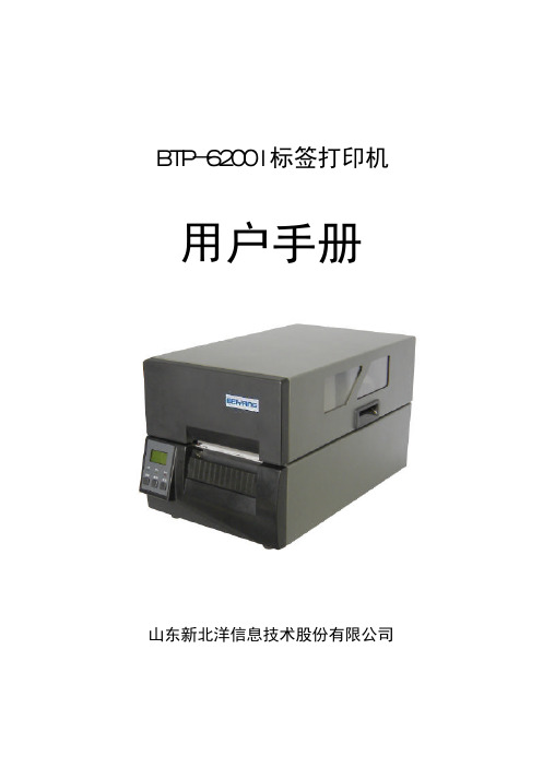
BTP-6200I标签打印机 用户手册山东新北洋信息技术股份有限公司 目录声明 (1)安全须知 (2)1概述 (3)1.1简介 (3)1.2主要特点 (3)2主要技术指标 (4)2.1主要技术规格 (4)2.2打印介质技术指标 (5)2.2.1打印纸技术指标 (5)2.2.2打印碳带技术指标 (5)2.3打印及出纸位置 (5)3外观和组件 (6)3.1外观和组件 (6)3.2主要组件介绍 (7)3.3指示灯、按键、液晶功能说明 (7)3.3.1指示灯功能说明 (7)3.3.2按键功能说明 (8)3.3.3液晶功能说明 (8)3.4告警指示灯和蜂鸣器 (9)3.5按键配置功能说明 (10)3.5.1按键配置模式下按键、指示灯功能说明 (10)3.5.2简单参数配置功能 (11)3.5.3复杂参数配置功能 (12)4通讯接口 (13)4.1串行接口 (13)4.1.1接口信号 (13)4.1.2接线示意图 (13)4.2并行接口 (14)5打印机的安装 (15)5.1开箱检查 (15)5.2打印机安装位置 (15)5.3连接电源 (15)5.4连接接口电缆 (15)5.5安装纸卷 (15)5.6安装碳带 (17)5.7启动打印机 (18)5.7.1开机与自检 (18)5.7.2打印自检样张 (18)5.7.3设置纸张类型 (18)5.7.4校验标记 (18)6打印机调节 (20)6.1打印头压力调节 (20)6.2打印头位置调节 (20)6.3传感器位置调节 (21)6.4打印机常用参数调整 (22)6.4.1打印机常用参数的调整及调整范围 (22)6.4.2票面上打印内容位置坐标及调整方向 (22)7打印机的日常维护 (24)7.1打印头清洁 (24)7.2传感器清洁 (24)7.3打印胶辊清洁 (24)8故障处理方法与维护 (26)8.1液晶错误信息显示 (26)8.2打印质量问题 (27)附录 (28)附录1 自检样张 (28)附录2 纸张的技术规格 (31)附录3 简单参数配置 (33)附录4 复杂参数配置 (34)声明 本手册内容未经同意不得随意更改,山东新北洋信息技术股份有限公司(以下简称新北洋)保留在技术、零部件、软件和硬件上变更产品的权利。
Dell PowerConnect 6200系列可堆叠交换机入门指南说明书
Dell™ PowerConnect™6200 Series Stackable SwitchesGetting Started Guide使用入门指南Příručka ZačínámeGuide de mise en routeErste SchritteΟδηγός για γρήγορο ξεκίνηµαはじめに시작 설명서Instrukcja uruchomieniaGuía de introducciónBaşlangıç KılavuzuModels PC6224, PC6248, PC6224P, PC6248P, and PC6224Fw w w.d e l l.c o m|s u p p o r t.d e l l.c o mDell™ PowerConnect™6200 Series Stackable SwitchesGetting Started GuideModels PC6224, PC6248, PC6224P, PC6248P, and PC6224Fw w w.d e l l.c o m|s u p p o r t.d e l l.c o mNotes, Notices, and CautionsNOTE: A NOTE indicates important information that helps you make better use of your computer.NOTICE: A NOTICE indicates either potential damage to hardware or loss of data and tells you how to avoid the problem.CAUTION: A CAUTION indicates a potential for property damage, personal injury, or death.____________________Information in this document is subject to change without notice.©2007Dell Inc.All rights reserved.Reproduction in any manner whatsoever without the written permission of Dell Inc.is strictly forbidden.Trademarks used in this text: Dell, the DELL logo, and PowerConnect are trademarks of Dell Inc.; Microsoft and Windows are registered trademarks of Microsoft Corporation.Other trademarks and trade names may be used in this document to refer to either the entities claiming the marks and names or their products. Dell Inc. disclaims any proprietary interest in trademarks and trade names other than its own.Models PC6224, PC6248, PC6224P, PC6248P, and PC6224FSeptember 2007P/N YC897Rev. A02Contents1InstallationSite Preparation (5)Unpacking the Switch (5)Package Contents (5)Unpacking Steps (6)Mounting the Switch (6)Installing in a Rack (6)Installing as a Free-standing Switch (7)Connecting a Switch to a Terminal (7)Connecting a Switch to a Power Supply (7)Assembling a Stack (8)2Starting and Configuring the SwitchConnecting the Terminal to the Switch (10)Booting the Switch (11)Initial Configuration (12)Initial Configuration Procedure (12)Example Session (13)Contents33Managing a StackMaster and Member Switches (16)Stack Startup (16)Topology Discovery (16)Auto Stack ID Assignment (16)Firmware Version Checking (16)System Initialization (17)CLI/ Telnet/ Web Interface (17)Insertion and Removal of Switches (17)Operating as Standalone Switch (17)Stack ID Renumbering (17)User Controls (18)4Front Panels and LEDsFront Panels (19)LEDs (20)Systems LEDs (20)RJ-45 LEDs (PoE) (21)XFP LED (21)SFP LED (21)4ContentsInstallationThis document provides basic information to install, configure, and operate Dell™PowerConnect™ PC6224, PC6248, PC6224P, PC6248P, and PC6224F systems. For more information, see the User's Guide, which is available on your User Documentation CD, or check the Dell Support web site at for the latest updates on documentation and firmware.Site PreparationPowerConnect 6200 series switches can be mounted in a standard 48.26-cm (19-inch) rack or left freestanding (placed on a flat surface). These switches can function as stand-alone switches. They can also be installed as a stack of switches that function, and are managed, as a single entity.Before installing the switch or switches, make sure that the chosen installation location meets the following site requirements:•Power — The switch is installed near an easily accessible 100–250 VAC, 50–60 Hz outlet. •Clearance — There is adequate front and rear clearance for operator access. Allow clearance for cabling, power connections, and ventilation.•Cabling — The cabling is routed to avoid sources of electrical noise such as radio transmitters, broadcast amplifiers, power lines, and fluorescent lighting fixtures.•Ambient — The ambient switch operating temperature range is 0 to 45ºC (32 to 113ºF) at a relative humidity of up to 95 percent, non-condensing.Unpacking the SwitchPackage ContentsWhen unpacking each switch, make sure that the following items are included:•One PowerConnect switch•One AC power cable•One RS-232 cable•One rack-mount kit for rack installation (two mounting brackets, bolts, and cage nuts)•One set of self-adhesive rubber pads for the free-standing switch (four pads are included)•User Documentation CD•Getting Started Guide•Product Information GuideGetting Started Guide56Getting Started Guidew w w .d e l l .c o m | s u p p o r t .d e l l .c o m Unpacking StepsNOTE: Before unpacking the switch, inspect the container and immediately report any evidence of damage.1Place the container on a clean, flat surface and cut all straps securing the container.2Open the container or remove the container top.3Carefully remove the switch from the container and place it on a secure and clean surface.4Remove all packing material.5Inspect the product and accessories for damage.Mounting the Switch CAUTION: Read the safety information in the Product Information Guide as well as the safety information for otherswitches that connect to or support the switch.The AC and DC power connectors are on the back panel of the switch. We recommend connecting a redundant power supply, such as the PowerConnect RPS-600 for non-PoE switches or the PowerConnect EPS-470 for PoE switches.Installing in a RackCAUTION: Do not use rack mounting kits to suspend the switch from under a table or desk, or attach it to a wall. CAUTION: Disconnect all cables from the switch before continuing. Remove all self-adhesive pads from theunderside of the switch, if they have been attached.CAUTION: When mounting multiple switches into a rack, mount the switches from the bottom up.1Place the supplied rack-mounting bracket on one side of the switch, ensuring that the mounting holes onthe switch line up to the mounting holes in the rack-mounting bracket. Figure 1-1 illustrates where tomount the brackets.Figure 1-1.Attaching the Brackets 2Insert the supplied bolts into the rack-mounting holes and tighten with a screwdriver. 3Repeat the process for the rack-mounting bracket on the other side of the switch.Getting Started Guide 74Insert the switch into the 48.26 cm (19 inch) rack, ensuring that the rack-mounting holes on the switch line up to the mounting holes in the rack.5Secure the switch to the rack with either the rack bolts or cage nuts and cage nut bolts with washers(depending on the kind of rack you have). Fasten the bolts on bottom before fastening the bolts on top.NOTICE: Make sure that the ventilation holes are not obstructed.CAUTION: Make sure that the supplied rack bolts fit the pre-threaded holes in the rack.Installing as a Free-standing Switch NOTICE:We strongly recommend mounting the switch in a rack.Install the switch on a flat surface if you are not installing it in a rack. The surface must be able to support the weight of the switch and the switch cables. The switch is supplied with four self-adhesive rubber pads.1Attach the self-adhesive rubber pads on each location marked on the bottom of the switch.2Set the switch on a flat surface, and make sure that it has proper ventilation by leaving 5 cm (2 inches)on each side and 13 cm (5inches) at the back.Connecting a Switch to a Terminal1Connect the supplied RS-232 cable to a VT100 terminal or to the serial connector of a personal computer running VT100 terminal emulation software.2Connect the female DB-9 connector at the other end of the RS-232 crossover cable to the serial portconnector on the rear of the switch.NOTE: If you are installing a stack of switches , connect the terminal to the Master Switch. This switch will light the Master Switch LED, the top left LED in the array on the front panel. When a stack is powered up for the first time, the switches elect the Master Switch, which may occupy any location in the stack. If you connect the terminal to a member switch, you will not be able to use the CLI.Connecting a Switch to a Power SupplyCAUTION: Read the safety information in the Product Information Guide as well as the safety information for other switches that connect to or support the switch.1Connect the supplied AC power cable to the AC power connector located on the back panel. Figure 1-2 illustrates where to connect the power cable.2To provide a redundant source of power, connect the 12 VDC power cable from a (separately purchased)PowerConnect RPS-600 for non-PoE switches or PowerConnect EPS-470 for PoE switches to the DC power connector located on the back panel.NOTE: Do not connect the power cable to a grounded AC outlet at this time. Connect the switch to a power source as described in the step detailed in "Starting and Configuring the Switch."8Getting Started Guide w w w .d e l l .c o m | s u p p o r t.d el l .c o m Figure 1-2.Connecting Power CableAssembling a StackY ou can stack PowerConnect 6200 series switches up to 12 switches high, supporting up to 576 front panel ports. Create a stack by connecting adjacent units using the stacking ports on the left side of the switch rear. See Figure 1-3.NOTE: The switches must be turned off as they are added to a stack.1Install a separately purchased stacking module in rear "Bay 1" in each of the switches to be stacked.2Use the cables supplied with the stacking modules to connect from one switch to the next until all switches are connected in a ring.3Make sure that the last stacking cable is connected from the last switch to the first switch to create a loop. 4If necessary, use a separately purchased three-meter stacking cable to connect the switches.Figure 1-3.Connecting a Stack of SwitchesNOTE: Long cable not shown in Figure1-3.The resulting ring topology allows the entire stack to function as a single switch with resilient fail-over capabilities.w w w .d e l l .c o m | s u p p o r t .d e l l .c o m Starting and Configuring the Switch After completing all external connections, connect a terminal to a switch to configure the switch or stack. Additional advanced functions are described in the User's Guide located on your User Documentation CD. NOTE: Read the release notes for this product before proceeding. You can download the release notes from the Dell Support website at . NOTE: We recommend that you obtain the most recent version of the user documentation from the Dell Support website at .Connecting the Terminal to the Switch To monitor and configure the switch via serial console, use the console port on the rear of the switch to connectit to a terminal desktop system running terminal emulation software. The console port connector is a male DB-9 connector, implemented as a data terminal equipment (DTE) connector.The following is required to use the console port:•VT100-compatible terminal or a desktop or a portable system with a serial port, running VT100 terminal emulation software.•An RS-232 crossover cable with a female DB-9 connector for the console port and the appropriateconnector for the terminal.Perform the following tasks to connect a terminal to the switch console port:NOTE: If you are installing a stack of switches , you need to assemble and cable the stack before powering upand configuring the stack.1Connect an RS-232 crossover cable to the terminal running VT100 terminal emulation software.2Configure the terminal emulation software as follows:aSelect the appropriate serial port (serial port 1 or serial port 2) to connect to the console.bSet the data rate to 9600 baud.cSet the data format to 8 data bits, 1 stop bit, and no parity.dSet the flow control to none.eSet the terminal emulation mode to VT100.f Select Terminal keys for Function, Arrow, and Ctrl keys. Make sure that the setting is for Terminal keys(not Microsoft ® Windows ® keys).NOTE: When using HyperTerminal with Microsoft Windows 2000, make sure that you have Windows 2000 Service Pack 2 or later installed. With Windows 2000 Service Pack 2, the arrow keys function properly in HyperTerminal's VT100emulation. Go to for more information on Windows 2000 service packs.3Connect the female connector of the RS-232 crossover cable directly to the switch console port, and tighten the captive retaining bolts. The PowerConnect 6200 series console ports are located on the rear panel as shown in Figure1-4.NOTE: If you are installing a stack of switches, connect the terminal to the Master Switch. This switch will light the Master Switch LED, the top left LED in the array on the front panel. When a stack is powered up for the first time, the switches elect the Master Switch, which may occupy any location in the stack. If you connect the terminal to a member switch, you will not be able to use the CLI.Figure 1-4.Connecting to the Console PortBooting the Switch1Make sure that the switch console port is connected to a VT100 terminal or VT100 terminal emulator via the RS-232 cable.2Locate an AC power receptacle.3Deactivate the AC power receptacle.4Connect the switch to the AC receptacle.5Activate the AC power receptacle.When the power is turned on with the local terminal already connected, the switch goes through a power-on self-test (POST). POST runs every time the switch is initialized and checks hardware components to determine if the switch is fully operational before completely booting. If POST detects a critical problem, the program flow stops. If POST passes successfully, valid firmware is loaded into RAM. POST messages are displayed on the terminal and indicate test success or failure. The boot process runs for approximately 60 seconds.w w w .d e l l .c o m | s u p p o r t .d e l l .c o m Initial Configuration NOTE: The initial simple configuration procedure is based on the following assumptions:•The PowerConnect switch was never configured before and is in the same state as when you received it.•The PowerConnect switch booted successfully.•The console connection was established and the Dell Easy Setup Wizard prompt appears on the screen of a VT100 terminal or terminal equivalent.The initial switch configuration is performed through the console port. After the initial configuration, you can manage the switch either from the already-connected console port or remotely through an interface defined during the initial configuration. NOTE: The switch is not configured with a default user name and password.NOTE: All of the settings below are necessary to allow the remote management of the switch through Telnet(Telnet client) or HTTP (Web browser).Before setting up the initial configuration of the switch, obtain the following information from your network administrator:•The IP address to be assigned to the management VLAN through which the switch is managed.•The IP subnet mask for the network.•The IP address of the management VLAN default gateway for configuring the default route.Initial Configuration ProcedureY ou can perform the initial configuration using the Dell Easy Setup Wizard, or by using the Command Line Interface (CLI). The Setup Wizard automatically starts when the switch configuration file is empty. Y ou can exit the wizard at any point by entering [ctrl+z], but all configuration settings specified will be discarded (the switch will use the default values). For more information on CLI initial configuration see the User Guide . This guide shows how to use the Setup Wizard for initial switch configuration. The wizard sets up the followingconfiguration on the switch:•Establishes the initial privileged user account with a valid password. The wizard configures one privileged user account during the setup. •Enables CLI login and HTTP access to use the local authentication setting only.•Sets up the IP address for the management VLAN.•Sets up the SNMP community string to be used by the SNMP manager at a given IP address. Y ou may choose to skip this step if SNMP management is not used for this switch. •Allows you to specify the management server IP or permit management access from all IP addresses.•Configures the default gateway IP address.Example SessionThis section describes an Easy Setup Wizard session. The following values are used by the example session:•IP address for the management VLAN is 192.168.1.100:255.255.255.0.•The user name is admin, and password is admin123.•The network management system IP address is 192.168.1.10.•The default gateway is 192.168.1.1.•The SNMP community string to be used is Dell_Network_Manager.The setup wizard configures the initial values as defined above. After you complete the wizard, the switchis configured as follows:•SNMPv1/2c is enabled and the community string is set up as defined above. SNMPv3 is disabled by default.•The admin user account is set up as defined.• A network management system is configured. From this management station, you can access the SNMP, HTTP, and CLI interfaces. Y ou may also choose to allow all IP addresses to access thesemanagement interfaces by choosing the (0.0.0.0) IP address.•An IP address is configured for the default management VLAN (1).• A default gateway address is configured.NOTE: In the example below, the possible user options are enclosed in [ ]. Also, where possible, the default value is provided in { }. If you press <Enter> with no options defined, the default value is accepted. Help text is in parentheses. The following example contains the sequence of prompts and responses associated with running an example Dell Easy Setup Wizard session, using the input values listed above.After the switch completes the POST and is booted, the following dialog appears:Welcome to Dell Easy Setup WizardThe setup wizard guides you through the initial switch configuration, and gets you up and running as quickly as possible. You can skip the setup wizard, and enter CLI mode to manually configure the switch. You must respond to the next question to run the setup wizard within 60 seconds, otherwise the system will continue with normal operation using the default system configuration. Note: You can exit the setup wizard at any point by entering [ctrl+z].Would you like to run the setup wizard (you must answer this question within 60 seconds)? [Y/N] y<Enter>w w w .d e l l .c o m | s u p p o r t .d e l l .c o m Step 1: The system is not configured for SNMP management by default. To manage the switch using SNMP (required for Dell Open Manage Network Manager) you can:o Set up the initial SNMP version 1 & 2 now.o Return later and set up other SNMP accounts. (For more information on setting up an SNMP version 3 account, see the user documentation). Would you like to configure the SNMP management interface now? [Y/N] y <Enter>To configure the SNMP management account you must specify the management system IP address and the "community string" or password that the particular management system uses to access the switch. The wizard automaticallyassigns the highest access level [Privilege Level 15] to this account. You can use Dell Open Manage Network Manager or other management interfaces to change this setting and to add additional management systems later. For more information on adding management systems, see the User’s Guide.To add a management station:Please enter the SNMP community string to be used {Dell_Network_Manager}: Dell_Network_Manager <Enter>NOTE: If it is configured, the default access level is set to the highest available access for the SNMP management interface. Initially only SNMPv1/2c will be activated. SNMPv3 is disabled until you return to configure security access for SNMPv3 (e.g. engine ID, view, etc.). Please enter the IP address of the Management System (A.B.C.D) or wildcard (0.0.0.0) to manage from any Management Station {0.0.0.0}: 192.168.1.10<Enter>Step 2:Now we need to configure your initial privilege (Level 15) user account. This account is used to login to the CLI and Web interface. You may set up other accounts and change privilege levels later. For more information on setting up user accounts and changing privilege levels, see the User’s Guide.To set up a user account:Please enter the user name {admin}: admin <Enter>Please enter the user password: ********<Enter>Please reenter the user password: ********<Enter>NOTE: If the first and second password entries are not identical, the user is prompted until they are.NOTE: You can create additional user accounts after completing the Easy Setup Wizard. See the User’s Guidefor more information.Step 3:Next, an IP address is set up. The IP address is defined on the default VLAN (VLAN #1), of which all ports are members. This is the IP address you use to access the CLI, Web interface, or SNMP interface for the switch.To set up an IP address:Please enter the IP address of the device (A.B.C.D):192.168.1.100<Enter>Please enter the IP subnet mask (A.B.C.D or /nn):255.255.255.0<Enter>Step 4:Finally, set up the gateway. Please enter the IP address of the gateway from which this network is reachable (e.g. 192.168.1.1): 192.168.1.1<Enter>This is the configuration information that has been collected:SNMP Interface = "Dell_Network_Manager"@192.168.1.10User Account set up = adminPassword = **********Management IP address = 192.168.1.100:255.255.255.0Gateway = 192.168.1.1Step 5:If the information is correct, please select (Y) to save the configuration, and copy to the start-up configuration file. If the information is incorrect, select (N) to discard configuration and restart the wizard: [Y/N] y<Enter>Thank you for using the Dell Easy Setup Wizard. You will now enter CLI mode.w w w .d e l l .c o m | s u p p o r t .d e l l .c o m Managing a Stack Master and Member Switches A stack of switches can be managed as a single entity when connected together. The stack can be managed from a web-based interface, an SNMP management station, or a CLI. When a stack is created, one switch automatically becomes the master switch. Y ou can manually allocate an IP address to the master switch using the console, or let DHCP do so automatically. Afterwards, you can manage the entire stack through the IP address of the Master Switch. The Master Switch detects and reconfigures the ports with minimal operational impact in the event of:•Switch failure •Inter-switch stacking link failure •Switch insertion •Switch removalIf the Master Switch goes off line, any of the Member Switches in the stack can replace it. The system will elect a new Master Switch and reconfigure the System Configuration for the stack.Stack StartupTopology DiscoveryWhen a stack is formed, a topology discovery process builds up a database that contains information about all of the switches in the stack, including the Firmware Version, Hardware Version, Management Preference, Switch MAC Address, and Switch Serial Number. Y ou can use the command line interface or the Web interface to view this information.See the CLI Reference Manual and the User’s Guide for assistance with the CLI and Web interface, respectively.Auto Stack ID AssignmentDuring the stack formation process, every switch is assigned a Stack ID. Once Stack ID assignment is complete, each switch saves its Stack ID into the nonvolatile FLASH memory. Y ou can use the CLI or the Web interface to view the stack IDs.Firmware Version CheckingFollowing Stack ID assignment, the Master Switch performs a consistency check to make sure that all switches in the stack are running the same firmware version.If the switch software versions do not match, then the ports on the member switch will not become valid for operation. This condition is known as the Suspended Stacking Mode. Y ou can then synchronize the firmware on the member switch with the firmware that is running on the Master Switch.System InitializationIf the Master Switch determines during the firmware version consistency check that all switches are running the same version of firmware, the switch will be initialized for Stacking Mode.System Initialization for Normal Stacking ModeThe Master Switch will initialize the stack using the last saved system configuration file. For those switches that do not have a configuration file, the system will apply default settings to those switches.If the configuration file is corrupted, the Master Switch will initialize the stack and set it to the Factory Default Configuration.Y ou can save the configuration file. The Master Switch will automatically distribute the configuration file to the member switches. If the Master Switch later becomes unavailable, a Member Switch can become the new Master Switch and apply the configuration file that was saved on the original Master Switch.System Initialization for Suspended Stacking ModeAfter system initialization is complete, the Master Switch will enter Suspended Stacking Mode if the firmware versions of the stack are inconsistent. In this mode, only the Master Switch is initialized with configuration file information. None of the member switches are initialized. This forces all member switches to remain in non-operational mode.CLI/ Telnet/ Web InterfaceY ou can use the CLI / WEB / SNMP to synchronize the firmware that is stored in the Master Switch to a member switch.Insertion and Removal of SwitchesY ou can insert and remove switches to/from the current stack without cycling the power. The entire network may be affected when a topology change occurs, as a stack reconfiguration will take place. A new Master Switch will not be re-elected, unless the Master Switch was removed from the stack. Stack reconfiguration takes a maximum of two minutes in a stack of twelve switches, less time for smaller stacks.Operating as Standalone SwitchIf a switch cannot detect a stacking partner on a port enabled for stacking, the switch will operate as a standalone switch. If a stacking partner is detected, the switch will always operate in stacking mode.Stack ID RenumberingY ou can manually assign Stack IDs to a switch. A switch can only be assigned a Stack ID that has not already been assigned to another switch in the stack. Any configuration information that was saved for the new Stack ID is applied to the switch that is taking that Stack ID.w w w .d e l l .c o m | s u p p o r t .d e l l .c o m User Controls Use the following CLI commands to control this feature. See the CLI Reference Guide for details on the syntax of each command.movemanagement reload member set description switch priority switch renumberstackingshow stack-portshow stack-port counters show stack-port diag show switchshow supported switchtypeFront Panels and LEDsThis appendix describes the front panels and LEDs of the Dell PowerConnect PC6224, PC6248, PC6224P, PC6248P, and PC6224F systems.Front PanelsThe front panels of the PowerConnect 6200 series systems are shown in the figures below.Figure 1-1.PC 6224PC 6248Figure 1-2.Figure 1-3.Getting Started Guide1920Getting Started Guidew w w .d e l l .c o m | s u p p o r t .d e l l .c o mFigure 1-4.PC 6248PFigure 1-5.PC 6224FLEDsThe following sections list the LEDs.Systems LEDsTable 1-1.System LEDsLED StateFan Status•Green: All Fans are operating correctly •Red: One or more fans have failed Power Supply Status •Green: PS operating correctly •Red: PS failureRedundant Power Supply•Green: Redundant supply present and operating correctly•Red: Redundant supply present and failed •Off: Redundant supply is not presentDiagnostic•Blinking Green: Diagnostics in progress•Solid Green: Diagnostics completed successfully •Red: Diagnostics failedTemperature•Green: System temperature is below threshold limit •Red: System temperature is above threshold limit。
Philips BT6000藍牙揚聲器使用手冊说明书

控制通話
在藍牙連線之後,您就能使用本揚聲器控 制來電。
按鈕 功能 按下即可接聽來電。 按住三秒即可拒絕來電。 通話時,按下即可結束目前通話。 通話時,按住三秒即可將來電轉接 到您的行動裝置。
重新連線裝置
當您開啟揚聲器時,揚聲器會自動重新連 線到上次連線的裝置;如果沒有,請在您 的藍牙裝置上選擇 [Philips BT6000] 以開始 連線。
188 x 70 x 71 公釐 0.5 公斤
10 ZH-TW
7 疑難排解
警告
• 請勿打開裝置外殼。
為維持有效的保固,請勿自行嘗試修理系 統。 如果您在使用本裝置時發生任何問題,請 在送修前先行檢查下列項目。 如果問題仍 未解決,請造訪 Philips 網頁 (www.philips. com/support)。 聯絡 Philips 時,手邊請先準 備好您的裝置、型號與序號。
注意 • 拆卸內建電池將導致保固失效,而且可能損壞本
產品。
若要取出產品的內建電池,請務必交由專 業人員處理。
環境保護資訊 所有非必要之包裝材料均已捨棄。 我們嘗 試讓包裝可以輕易拆解成三種材質:厚紙 板 (外盒)、聚苯乙烯泡棉 (防震) 以及聚乙 烯 (包裝袋、保護性泡棉膠紙)。 產品本身含有可回收並重複使用的材質, 但是需由專業公司拆解。 請根據各地法規 丟棄包裝材料、廢電池和舊機器。
一般
沒有電力 • 確定裝置的 AC 電源插頭已妥善連接。 • 請確認 AC 電源插座有電。 • 為揚聲器進行充電。 沒有聲音 • 調整本產品的音量。 • 調整連線裝置上的音量。 • 請確定您的藍牙裝置位於有效操作範
圍內。 揚聲器沒有反應 • 將電源插頭拔除後再插入,然後再開啟
BlackBerry 6200 系列 无线掌上电脑 说明书

用户指南,BlackBerry 6700 系列,BlackBerry 6200 系列,BlackBerry 7200 系列,BlackBerry 7700 系列BlackBerry 6210 Wireless Handheld™ 型号:R6220GWBlackBerry 6220 Wireless Handheld™ 型号:R6220GEBlackBerry 6230 Wireless Handheld™ 型号:R6231GEBlackBerry 6280 Wireless Handheld™ 型号:RAO31GNBlackBerry 6710 Wireless Handheld™ 型号:R6020GWBlackBerry 6720 Wireless Handheld™ 型号:R6020GEBlackBerry 7210 Wireless Handheld™ 型号:R6230GEBlackBerry 7230 Wireless Handheld™ 型号:R6230GEBlackBerry 7280 Wireless Handheld™ 型号:RAO30GNBlackBerry 7730 Wireless Handheld™ 型号:R6030GEBlackBerry 7780 Wireless Handheld™ 型号:R6030GN上次修改日期:2005 年 4 月 19 日部件号:SWD_X_HH(EN)-041.011本文档出版时依照掌上电脑软件版本 4.0.2 为准。
© 2005 Research In Motion Limited。
保留所有权利。
BlackBerry 和 RIM 相关标记、图像和符号系列是 Research In Motion Limited 的专有财产和商标。
RIM、Research In Motion、“Always On,Always Connected”和 BlackBerry 已在美国专利和商标局注册,并可能正在申请或已在其它国家(地区)注册。
- 1、下载文档前请自行甄别文档内容的完整性,平台不提供额外的编辑、内容补充、找答案等附加服务。
- 2、"仅部分预览"的文档,不可在线预览部分如存在完整性等问题,可反馈申请退款(可完整预览的文档不适用该条件!)。
- 3、如文档侵犯您的权益,请联系客服反馈,我们会尽快为您处理(人工客服工作时间:9:00-18:30)。
-1-
BTP-6200I 用户手册 5.1 开箱检查 ....................................................................................................................................................... 15 5.2 打印机安装位置 ........................................................................................................................................... 15 5.3 连接电源 ....................................................................................................................................................... 15 5.4 连接接口电缆 ............................................................................................................................................... 15 5.5 安装纸卷 ....................................................................................................................................................... 16 5.6 安装碳带 ....................................................................................................................................................... 17 5.7 启动打印机 ................................................................................................................................................... 18