periodical__zhyxtsgzz__zhyx2010__1001pdf__100123
7KH 'HVLJQHU·V XLGH GRZQORDGHG IURP ZZZ GHVLJQHUV JXLGH FRP Modeling Diffusion Resistors

overcomes many of the problems inherent to the common two-terminal model.
Last updated on January 1, 2004. You can find the most recent version at . Contact the author via e-mail at ken@. Permission to make copies, either paper or electronic, of this work for personal or classroom use is granted without fee provided that the copies are not made or distributed for profit or commercial advantage and that the copies are complete and unmodified. To distribute otherwise, to publish, to post on servers, or to distribute to lists, requires prior written permission. Copyright 2004, Kenneth S. Kundert – All Rights Reserved
This models is linear with respect to vdiff and nonlinear with a first-order dependence with respect to vavg. The coefficients for the resistance, cr, and the conductance, cg, can be related as follows. 1 -, g ( v avg ) = --------------r ( v avg ) 1 g 0 ( 1 + c g v avg ) = -------------------------------- , ( 1 + c r v avg ) r 0 ( 1 – c r v avg ) -, ( 1 + c g v avg ) = -----------------------------------------------------( 1 + c r v avg ) ( 1 – c r v avg ) ( 1 – c r v avg ) ( 1 + c g v avg ) = ---------------------------------. ( 1 – ( c r v avg ) 2 ) Assuming (crvavg)2 « 1 gives ( 1 + c g v avg ) ≈ ( 1 – c r v avg ) , or cg ≈ –cr . (11) (10) (6) (7) (8) (9)
TestKing 1Z0-025 V2.1
1Z0 - 025Leading the way in IT testing and certification tools, Important NotePlease Read CarefullyStudy TipsThis product will provide you questions and answers along with detailed explanations carefully compiled and written by our experts. Try to understand the concepts behind the questions instead of cramming the questions. Go through the entire document at least twice so that you make sure that you are not missing anything.Latest VersionWe are constantly reviewing our products. New material is added and old material is revised. Free updates are available for 90 days after the purchase. You should check for an update 3-4 days before you have scheduled the exam.Here is the procedure to get the latest version:1.Go to 2.Click on Login (upper right corner)3.Enter e-mail and password4.The latest versions of all purchased products are downloadable from here. Just click the links.Note: If you have network connectivity problems it could be better to right-click on the link and choose Save target as. You would then be able to watch the download progress.For most updates it enough just to print the new questions at the end of the new version, not the whole document.FeedbackFeedback on specific questions should be send to feedback@. You should state1.Exam number and version.2.Question number.3.Order number and login ID.We will answer your mail promptly.CopyrightEach pdf file contains a unique serial number associated with your particular name and contact information for security purposes. So if you find out that particular pdf file being distributed by you. Testking will reserve the right to take legal action against you according to the International Copyright Law. So don’t distribute this PDF file.Leading the way in IT testing and certification tools, QUESTION NO: 1What are two benefits of using RMAN with a catalog? (Choose two)A.You can copy the redo-log history into the control file.B.You can store scripts for backup and recovery operations.C.You can register the target database with recovery catalog.D.You can maintain records of backup and recovery operations.E.You can synchronize the recovery catalog and the target database.Answer: B, DExplanation:There are two benefits of using RMAN with a catalog: you can store scripts for backup and recovery operations and maintain records of backup and recovery operations.Incorrect Answers:A:You cannot copy the redo-log history into the control file with catalog or without it.C:The target database can be registered with recovery catalog and without it.E:You can synchronize the recovery catalog and the target database using RESYNC CATALOG command, but the recovery catalog is not updated when a log switch occurs, when a log file is archived, or when datafiles or redo logs are added.Oracle 8, DBA Certification Exam Guide, Jason S. Couchman, p. 615-623Chapter 13: Using Recovery Manager for BackupsQUESTION NO: 2What is recommended initial size for a tablespace containing an RMAN recovery catalog?A.10MB.20MC.100MD.10% of size of the target database.Answer: AExplanation:It’s recommended to use a tablespace for RMAN with 10M, this tablespace will be relatively small. Incorrect Answers:B:It is more then enough for RMAN tablespace if you create a tablespace with 20M size.C:Size 100M is extremely high level for RMAN tablespace.D:Size of tablespace for RMAN catalog is not related with size of the target database.Leading the way in IT testing and certification tools, Oracle 8, DBA Certification Exam Guide, Jason S. Couchman, p. 618Chapter 13: Using Recovery Manager for BackupsQUESTION NO: 3Your daily report indicating which data files need to be backed up has been misplaced. Which recovery manager command returns a report containing the files in the USER_DATA tablespace that have not been backed up within the last three days?A.Rman> list backup day 3 tablespace user_data;B.Rman> report backup days 3 tablespace user_data;C.Rman> catalog backup days 3 tablespace user_data;D.Rman> report need backup days 3 tablespace user_data;Answer: DExplanation:This command shows all files in the USER_DATA tablespace required backups within the last three days. Incorrect Answers:A:This command will not provide requested information.B:This command will not provide requested information.C:This command will not provide requested information.Oracle 8, DBA Certification Exam Guide, Jason S. Couchman, p. 625-626Chapter 13: Using Recovery Manager for BackupsQUESTION NO: 4Which command is used to allow RMAN to store a group of commands in the recovery catalog?A.ADD SCRIPTB.CREATE SCRIPTC.CREATE COMMANDD.ADD BACKUP SCRIPTAnswer: BExplanation:Leading the way in IT testing and certification tools, CREATE SCRIPT command is used to allow RMAN to store a group of commands in the recovery catalog. Scripts are created in RMAN using the CREATE SCRIPT command. Once created, the script is an object stored in the recovery catalog, and it will be backed up as part of the recovery catalog.Incorrect Answers:A:There is no ADD SCRIPT command in RMAN.C:There is no command CREATE COMMAND in RMAN.D:There is no ADD BACKUP SCRIPT command in RMAN.Oracle 8, DBA Certification Exam Guide, Jason S. Couchman, p. 627-628Chapter 13: Using Recovery Manager for BackupsQUESTION NO: 5After rebuilding the recovery catalog by resynchronizing it with a copy of the backup control file, you notice references to files that no longer exist. Which CREATE command clause should you use to remove these references?A.REMOVEB.DELETEC.UNCATALOGD.CATALOG REMOVEAnswer: CExplanation:You need to use UNCATALOG clause to remove references to files that no longer exist.Incorrect Answers:A:REMOVE clause will not remove references to files that no longer exist.B:DELETE clause will not remove references to files that no longer exist.D:There is no CATALOG REMOVE clause in RMAN exists.Oracle 8, DBA Certification Exam Guide, Jason S. Couchman, p. 625Chapter 13: Using Recovery Manager for BackupsQUESTION NO: 6What are two purposes for using the recovery manager command CATALOG? (Choose two)A.Updating recovery catalog about rollback segment creation.Leading the way in IT testing and certification tools, B.Updating recovery catalog about files created before RMAN.C.Updating recovery catalog about operating systems backup.D.Updating recovery catalog about files created before Oracle 8.E.Updating recovery catalog about files that belong to a clone database.Answer: B, CExplanation:Command CATALOG is used to update recovery catalog about files created before RMAN and about operating systems backup. A datafile image copy, backup control file, or archived redo log taken using methods other than RMAN can be used by RMAN if it is identified to the recovery catalog with the CATALOG command. Only files that are part of the database can be part of the recovery catalog for that database.Incorrect Answers:A:RMAN recovery catalog does not work with rollback segments itself.D:Only Oracle8 files can be cataloged, RMAN recovery catalog does not work with earlier versions of Oracle.E:Both the target database and the recovery catalog must be defined for this operation to work. This command does not work with the clone database.Oracle 8, DBA Certification Exam Guide, Jason S. Couchman, p. 625Chapter 13: Using Recovery Manager for BackupsQUESTION NO: 7What is the advantage of managed recovery mode?A.During recovery, most common DBA errors can be avoided.B.Prompts for applying the next available redo logs suppressed.C.The primary database automatically ships archived redo log files to the standby server.D.The standby database automatically applies the archived redo log when the files become available. Answer: DExplanation:The main advantage of managed recovery mode is that the standby database automatically applies the archived redo log when the files become available to keep the target database and the standby database in synchronization.Incorrect Answers:A:The managed recovery mode of standby databases is not used just to avoid most common DBA errors. B:Standby databases do not use prompts for applying the next available redo logs.Leading the way in IT testing and certification tools, C:The primary database automatically ships archived redo log files to the standby server not because of managed recovery mode, but because of init.ora file initialization parameters of the primary database. Oracle 8, DBA Certification Exam Guide, Jason S. Couchman, p. 1159Chapter 24: Oracle8i New Features TopicsQUESTION NO: 8What is the effect of issuing an ALTER DATABASE OPEN RESETLOGS command on the primary database?A.It invalidates the standby database.B.The standby database can only be used in read-only mode.C. A new standby database incarnation will automatically be started.D.Once the archived log files are applied to the standby database, the redo log of the standby databaseis reset.Answer: AExplanation:Resetting redo logs for the primary database will invalidate the standby database, it needs to be recreated from the primary database again.Incorrect Answers:B:The standby database cannot be used in any mode, it needs to be rebuild again.C: A new standby database incarnation will not automatically be started because of invalidation of standby database.D:The redo log of the standby database will not be reset automatically, no new archive logs can be applied to the standby database because of reset logs in the primary database.Oracle 8, DBA Certification Exam Guide, Jason S. Couchman, p. 1159Chapter 24: Oracle8i New Features TopicsQUESTION NO: 9What is the effect of activating a standby database?A.The primary database becomes a standby database.B.The standby database becomes the primary database.C.The primary database is deactivated to avoid conflicts.D.The remaining redo-log files are copied from the primary database and applied.Leading the way in IT testing and certification tools, Answer: BExplanation:The main effect of activating a standby database is that the standby database becomes the primary database. Incorrect Answers:A:Old primary database can be used as standby database for new primary database after that, but this is not mandatory.C:The primary database still can be active and used as standby database, for example.D:After switchover between the primary and the standby database no more redo log files can be applied to the standby database, because of it’s already the primary database and all redo logs for it have beenreset.Oracle 8, DBA Certification Exam Guide, Jason S. Couchman, p. 1159Chapter 24: Oracle8i New Features TopicsQUESTION NO: 10What is the difference between using NOLOGGING operations in a single database environment and a standby database environment?A.There is no difference.B.NOLOGGING operations are not available in release 0.1C.The affected data file needs to be copied from the primary to the standby server.D.NOLOGGING operations can be used on the standby database, but not on the primary database. Answer: CExplanation:NOLOGGING operations affect a standby database environment, because changes in the primary database will not be written into redo logs and will not be applied to the standby database, so the affected data files needs to be copied from the primary to the standby database manually. It’s better to avoid NOLOGGING operation usage in a standby database environment.Incorrect Answers:A:There is a difference in these two situations.B:There is no release 0.1.D:NOLOGGING operations can be used on the primary database only. Changes to the standby database will be applied with physical datafiles copying, not with archived redo log files applying only.Oracle 8, DBA Certification Exam Guide, Jason S. Couchman, p. 1159Leading the way in IT testing and certification tools, Chapter 24: Oracle8i New Features TopicsQUESTION NO: 11The command ALTER DATABASE CREATE STANDBY CONTROLFILE AS standby.ct creates a standby control file. What needs to be done next to create a standby database?A.The standby control file needs to be copied to the standby server.B.The current redo-log files of the primary database need to be archived.C.The standby database needs to be created using the standby control file.D.The standby control file needs to be copied to the standby location on the primary server. Answer: BExplanation:The current redo-log files of the primary database need to be archived after the command ALTER DATABASE CREATE STANDBY CONTROLFILE.Incorrect Answers:A:The standby control file does not need to be copied to the standby server.C:The standby database does not need to be created using the standby control file.D:The standby control file needs to be copied to the standby location on the primary server, because there is no standby location on the primary server.Oracle 8, DBA Certification Exam Guide, Jason S. Couchman, p. 1159Chapter 24: Oracle8i New Features TopicsQUESTION NO: 12What is the correct procedure for multiplexing existing online redo logs?A.Issue the ALTER DATABASE. . . ADD LOGFILE GROUP command.B.Issue the ALTER DATABASE. . . ADD LOGFILE MEMBER command.C.Shut down the database, copy the online redo-log, and start up the database.D.Shut down the database, copy the online redo-log, edit the REDO_LOG_FILES parameter, and startup the database.Answer: BExplanation:Leading the way in IT testing and certification tools, Command ALTER DATABASE . . ADD LOGFILE MEMBER is used for multiplexing existing online redo logs, it adds members to redo log file. Each member needs to be placed on separate disks to decrease possibility of corrupting all members of the group.Incorrect Answers:A:This command just creates new group, it has nothing to do with multiplexing.C:You don’t need to shut down the database to multiplex existing online redo logs.D:You don’t need to shut down the database to multiplex existing online redo logs.Oracle 8, DBA Certification Exam Guide, Jason S. Couchman, p. 572-574Chapter 12: Overview of Backup and RecoveryQUESTION NO: 13Which statement concerning archiving is true?A.Archiving occurs during a checkpoint.B.Archive logs can be written to multiple destinations.C.Backups are not required when archiving is enabled.D.Archiving copies the data files to their backup destinations.E.Archiving can be enabled through recovery manager commands.Answer: BExplanation:Archive logs can be written to multiple destinations. Oracle allows you to multiplex your archived redo logs by specifying a few new init.ora parameters. The first is LOG_ARCHIVE_DUPLEX_DEST, and it’s used to identify the second location where Oracle will store copies of archived redo logs. The second new init.ora parameter is the LOG_ARCHIVE_MIN_SUCCEED_DEST parameter. This is set a number indicating how many archive log copies Oracle should maintain.Incorrect Answers:A:Archiving works constantly, not only during a checkpoint.C:Backups are required always, with enabled archiving also.D:Archiving works only with redo log files, not with data files.E:Archiving cannot be enabled trough recovery manager commands.Oracle 8, DBA Certification Exam Guide, Jason S. Couchman, p. 583-585Chapter 12: Overview of Backup and RecoveryLeading the way in IT testing and certification tools, QUESTION NO: 14What is the function of SMON in instance recovery?A.It writes data to the archive log files.B.It writes data to the online redo log files.C.It frees resources held by user processes.D.It synchronizes data file header and control files.E.It roles forward by applying changes in the redo log.F.It writes dirty buffers from the buffer cache to the data files.Answer: EExplanation:SMON is Oracle background process, which handles instance recovery after database startup if necessary, and periodically coalesces smaller chunks of free space in tablespaces into larger chunks. The main function of SMON in instance recovery is to roll forward transactions applying changes in the redo log files. Also a function of SMON in Oracle8 is to deallocate space in temporary segments no longer in use.Incorrect Answers:A:SMON does not write data anywhere itself, ARCH process writes data to the archive log files.B:SMON does not write data anywhere itself, LGWR process writes data changes into redo log files. C:PMON process frees resources held by user processes, not SMON.D:CKPT process synchronizes data file header and control file.F:DBWR background process writes dirty buffers from the buffer cache to the datafiles.Oracle 8, DBA Certification Exam Guide, Jason S. Couchman, p. 565Chapter 12: Overview of Backup and RecoveryQUESTION NO: 15What is the function of ARCn in instance recovery?A.It writes data to the archive log files.B.It writes data to the online redo log files.C.It frees resources held by user processes.D.It synchronizes data file header and control files.E.It writes dirty buffers from the buffer cache to the data files.F.The archive process does not take part in instance recovery.Answer: FExplanation:Leading the way in IT testing and certification tools, ARCH process does not work in instance recovery itself. SMON background process just may use archived by ARCH process redo log files for recovery purposes.Incorrect Answers:A:ARCH process writes data to the archive log files, but it has nothing to do with instance recovery process.B:LGWR process writes data changes into redo log files, not ARCH.C:PMON process frees resources held by user processes.D:CKPT process synchronizes data file header and control file.E:DBWR background process writes dirty buffers from the buffer cache to the data files, not ARCH. Oracle 8, DBA Certification Exam Guide, Jason S. Couchman, p. 657Chapter 14: Database Failure and RecoveryQUESTION NO: 16What are two causes of user errors? (Choose two)A.Incorrect data is committed.B.The operating system crashes.C.There are insufficient privileges.D. A table is accidentally truncated.E.An application file is accidentally deleted.F.The application program receives an addressing exception.Answer: A, DExplanation:There are two types of user errors: committed incorrect data and accidentally truncated or dropped table. Dropped tables or other objects and committed changes may require DBA intervention and the use of EXPORT, IMPORT, and other backup and recovery strategies. Usually, the DBA will need to recover the entire database to another machine, export the dropped or deleted object data, and restore the object to the appropriate environment. You may see this situation occur quite a bit in development environments where the developers are their own DBAs. To avoid this problem in production, only the DBA should be allowed to create, alter, or drop database objects. By controlling the introduction, change, or removal of database objects in your production system, you reduce the likelihood that users become dependant upon an unrecoverable database object.Incorrect Answers:B:Usually operation system crash is not user error.Leading the way in IT testing and certification tools, C:Insufficient privileges do not cause user error.E:It’s not user error if application file is accidentally deleted.F:If application program receives an addressing exception it’s application error, not user one.Oracle 8, DBA Certification Exam Guide, Jason S. Couchman, p. 656Chapter 14: Database Failure and RecoveryQUESTION NO: 17Which option is used in the parameter file to detect corruptions in an Oracle data block?A.DBVERIFYB.DBMS_REPAIRC.DB_BLOCK_CHECKINGD.VALIDITY_STRUCTUREAnswer: CExplanation:DB_BLOCK_CHECKING parameter in the parameter file set to TRUE will force Oracle to check Oracle database data blocks for corruption.Incorrect Answers:A: Verification of structural integrity of Oracle database files is done with the DBVERIFY utility.DBVERIFY is a utility that verifies the integrity of a datafile backup or production file. It can be used either to verify that a backup is usable, to verify the usability of a production database, or to diagnose where corruption is suspected on a datafile or backup. But DBVERIFY is Oracle utility, not a parameter in the parameter file.B: DBMS_REPAIR is a package to detect data corruption, but it’s not a parameter in the parameter file. D: There is no VALIDITY_STRUCTURE parameter in the Oracle parameter file.Oracle 8, DBA Certification Exam Guide, Jason S. Couchman, p. 659-663Chapter 14: Database Failure and RecoveryQUESTION NO: 18Which statement is true when using the LogMiner utility?A.The dictionary file is created in a directory as defined by UTL_FILE_DIR.B.The CREATE DBMS LOGMSR command is used to build the dictionary file.C.The dictionary file must be created after the log file analysis has completed.Leading the way in IT testing and certification tools, D.The dictionary file is created as a backup if the data dictionary gets corrupted.Answer: AExplanation:The dictionary file will be created in a directory defined by UTL_FILE_DIR parameter in the parameter file. Incorrect Answers:B:There is no CREATE DBMS LOGMSR command in Oracle.C:The dictionary file must be created BEFORE the log file analysis has completed.D:The dictionary file is not used as a backup if the data dictionary gets corrupted.Oracle 8, DBA Certification Exam Guide, Jason S. Couchman, p. 1160Chapter 24: Oracle8i New Features TopicsQUESTION NO: 19Which statement is true when using the DBVERIFY utility to detect corruptions in an Oracle data block?A.The utility can only be invoked on a data file that is online.B.The utility can be used to verify the data files of a backup database.C.The utility can assist in archiving log files when the database load is high.D.The utility is internal to the database and so can impact database activates.Answer: BExplanation:The verification of structural integrity of Oracle database files is done with the DBVERIFY utility. DBVERIFY is a utility that verifies the integrity of a datafile backup or production file. It can be used either to verify that a backup is usable, to verify the usability of a production database, or to diagnose where corruption is suspected on a datafile or backup. The utility can be used to verify the data files of a backup database.Incorrect Answers:A:DBVERIFY utility does not work with online data files.C:This utility cannot be used to archive log files.D:This utility is external to database and cannot impact database activities.Oracle 8, DBA Certification Exam Guide, Jason S. Couchman, p. 659-661Chapter 14: Database Failure and RecoveryLeading the way in IT testing and certification tools, QUESTION NO: 20The alert log can contain specific information about which database backup activity?A.Placing datafiles in begin and end backup mode.B.Placing tablespace in begin and end backup mode.C.Changing the database backup mode from open to close.D.Performing an operating system backup of the database files.Answer: BExplanation:The alert log contains only information about placing tablespaces in begin and end backup modes.Incorrect Answers:A:The alert log file does not show information about placing individual datafiles in begin and end backup modes, only about tablespaces.C:There are no open or close backup modes in Oracle.D:The alert log file does not contain information about an operation system backup.Oracle 8, DBA Certification Exam Guide, Jason S. Couchman, p. 588-590Chapter 12: Overview of Backup and RecoveryQUESTION NO: 21In which two situations would you have to apply redo information to a read-only tablespace? (Choose two)A.When the tablespace being recovered has always been writeable.B.When the tablespace being recovered is unknown to the control file.C.When the tablespace being recovered is read-only and was read-only when the last backup occurred.D.When the tablespace being recovered is writeable, but was read-only when the last backup occurred.E.When the tablespace being recovered is read-only, but was writeable when the last backup occurred. Answer: D, EExplanation:You should apply redo log changes if the tablespace being recovered is writeable, but was read-only when the last backup occurred or when the tablespace being recovered is read-only, but was writeable when the last backup occurred..Incorrect Answers:A:If the tablespace being recovered has always been writeable, it is not in read-only mode.Leading the way in IT testing and certification tools, B:You cannot apply redo logs to the tablespace being recovered is unknown to the control file.C:If the tablespace being recovered is read-only and was read-only when the last backup occurred you don’t need to apply redo logs to it, because there are no changes to it.Oracle 8, DBA Certification Exam Guide, Jason S. Couchman, p. 593Chapter 12: Overview of Backup and RecoveryQUESTION NO: 22Which two types of data files can be considered non-essential? (Choose two)A.Data files belonging to a lost tablespace.B.Data files belonging to an index tablespace.C.Data files belonging to a SYSTEM tablespace.D.Data files belonging to a temporary tablespace.E.Data files belonging to an application data tablespace.F.Data files belonging to a rollback segment tablespace.Answer: C, FExplanation:The data files belonging to a SYSTEM and a rollback segment tablespaces can be considered non-essential, because you need a SYSTEM tablespace to startup database at least and rollback segment tablespace to rollback not committed information. The loss of SYSTEM tablespace datafiles or datafiles from tablespaces containing rollback segments may cause Oracle to stop running.Incorrect Answers:A:Data files belonging to a lost tablespace cannot be considered non-essential.B:Data files belonging to an index tablespace cannot be considered non-essential.D:Data files belonging to a temporary tablespace cannot be considered non-essential.E:Data files belonging to an application data tablespace cannot be considered non-essential.Oracle 8, DBA Certification Exam Guide, Jason S. Couchman, p. 676Chapter 14: Database Failure and RecoveryQUESTION NO: 23In which situation would you need to create a new control file for an existing database?A.When all redo-log files are lost.B.When MAXLOGMEMBERS needs to be changed.Leading the way in IT testing and certification tools, C.When RECOVERY_PARALLELISM needs to be changed.D.When the name of the parameter file needs to be changed.Answer: BExplanation:You need to recreate a control file if MAXLOGMEMBERS parameter needs to be changed. You may encounter situations requiring you to reconstruct or replace a lost or damaged control file on your Oracle database. Several situations indicate this need, including loss of all control files for your database due to media failure, needing to change option settings specified in your CREATE DATABASE statement (MAXLOGFILES, MAXDATAFILES, MAXLOGMEMBERS, and others), and wanting to change the name of the database.Incorrect Answers:A:You don’t need to create a new control file when all redo log files a lost.C:You don’t need to create a new control file when RECOVERY_PARALLELISM needs to be changed. D:You don’t need to create a new control file if the name of the parameter file is changed.Oracle 8, DBA Certification Exam Guide, Jason S. Couchman, p. 719-720Chapter 15: Advanced Topics in Data RecoveryQUESTION NO: 24A tablespace becomes unavailable because of a failure. The database is running in NOARCHIVELOG mode? What should the DBA do to make the database available?A.Perform a tablespace recovery.B.Perform a complete database recovery.C.Restore the data files, redo log files, and control files from an earlier copy of a full database backup.D.There is no possibility too make the database available.Answer: BExplanation:If there is no media failure to make the database available you need to perform a complete database recovery. Incorrect Answers:A:You cannot to perform a tablespace recovery to fix this problem because your database is in NOARCHIVELOG mode.C:It’s possible to use this way for database availability in case of media failure, but to fix problem just with one tablespace you can perform a complete database recovery.D:It’s possible to make the database available for work.Leading the way in IT testing and certification tools, 。
产品常见问题

产品常见问题书生卡问题1、书生卡驱动程序安装不上(“没找到相应硬件,请检查硬件是否插好”-)解决方法:1)我的电脑点击鼠标右键-属性-硬件-设备管理器,在有黄色警告的选项上点击鼠标右键-更新驱动程序(或选中PCI简易通讯控制器)2)选择从列表或指定位置安装3)不要搜索。
我要自己选择要安装的驱动程序。
4)选择硬件时,选择多功能卡,选中后,点右边的从磁盘安装5)在弹出的对话框中点浏览,找光盘中的文件6)继续安装后出现界面再点浏览,找win2000中的的文件 .2、书生卡安装错误报“名称已用作服务名或者服务显示名”1)把光盘下的win2000下的文件拷到电脑中,将文件的名字改为2)我的电脑点击鼠标右键-属性-硬件-设备管理器,在有黄色警告的选项上点击鼠标右键-更新驱动程序3)选择从列表或指定位置安装4)不要搜索。
我要自己选择要安装的驱动程序。
5)选择硬件时,选择多功能卡,选中后,点右边的从磁盘安装6)在弹出的对话框中点浏览,找光盘Win98下的文件7)继续安装后出现界面再点浏览,找电脑中改过名字的文件3、设备管理器右边书生卡的驱动显示为:PCI Multi-IO Controller正常显示为解决方法:重新更新书生卡驱动,步骤同问题14、设备管理器中书生卡驱动显示正常,但还是不能盖章等操作sep1程序:检查帮助菜单—关于,是否能够查到书生卡号,能看到卡号才是正常的。
若不正常,请用橡皮擦擦下书生卡金属片防止氧化或更换插槽、更换机器试下,如果还不可以,需要换卡。
sep2程序:检查C:\Program Files\Sursen\Sedcore里文件,获取书生卡硬件信息,看能不能识别到卡号。
若不正常,请用橡皮擦擦下书生卡金属片防止氧化或更换插槽、更换机器试下,如果还不可以,需要换卡。
5、飞天key-----手动删除的方法1)Program Files目录下如有ngsrv目录,删除。
2)system32目录下删除ng开头的文件。
实验平台安装

電子地圖 車輛移動模型
NS-2
首先取得 ns-allinone-2.34.tar.gz 檔案
這裡面將包括
ns-2.34 tcl8.4.18 tk8.4.18 nam-1.14 otcl-1.13 以上套件
NS-2
我們將把ns-2安裝在 /home/user資料夾 下
User為目前所使用的帳號名稱
假設我們將ns-allinone-2.34.tar.gz檔案 放在隨身碟中,我們要將此檔案複製到 /home/user之下
cp /media/隨身碟名稱/ns-allinone2.34.tar.gz /home/user/
在此我們建議隨身碟名稱不要使用中文名稱。
NS-2
接著我們進到/home/user資料夾下
SIP communicator
An audio/video Internet phone and instant messenger Completely Open Source / Free Software Freely available under the terms of the GNU Lesser General Public License. /
Click left bottom text box to enter SIP username Next to password and optionally select an endpoint to redirect calls when this endpoint is off-line then “Add/Update” button.
Oscar Setup
在C:\oscar路徑下輸入java –jar oscar-1.0.5.jar
TM_Lp-115_June20101
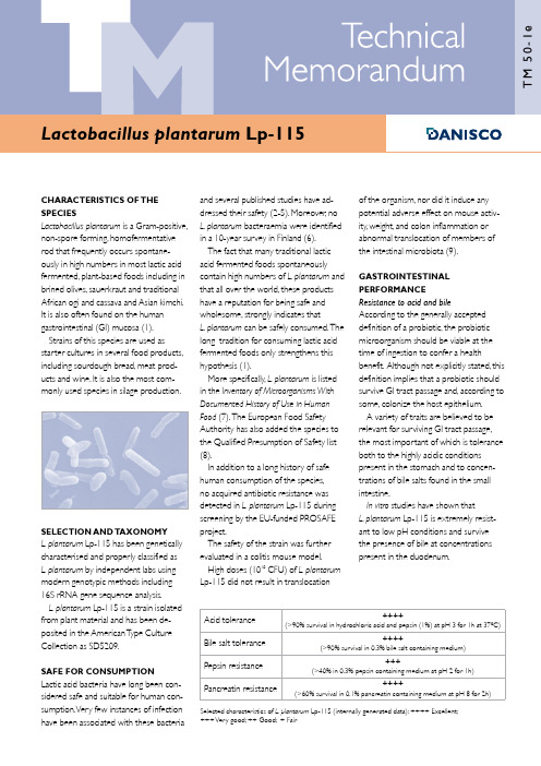
CHARACTERISTICS OF THESPECIESLactobacillus plantarum is a Gram-positive,non-spore forming, homofermentativerod that frequently occurs spontane-ously in high numbers in most lactic acidfermented, plant-based foods including inbrined olives, sauerkraut and traditionalAfrican ogi and cassava and Asian kimchi.It is also often found on the humangastrointestinal (GI) mucosa (1).Strains of this species are used asstarter cultures in several food products,including sourdough bread, meat prod-ucts and wine. It is also the most com-monly used species in silage production.SELECTION AND TAXONOMYL. plantarum Lp-115 has been geneticallycharacterised and properly classified asL. plantarum by independent labs usingmodern genotypic methods including16S rRNA gene sequence analysis.L. plantarum Lp-115 is a strain isolatedfrom plant material and has been de-posited in the American T ype CultureCollection as SD5209.SAFE FOR CONSUMPTIONLactic acid bacteria have long been con-sidered safe and suitable for human con-sumption. Very few instances of infectionhave been associated with these bacteria and several published studies have ad-dressed their safety (2-5). Moreover, no L. plantarum bacteraemia were identified in a 10-year survey in Finland (6).The fact that many traditional lactic acid fermented foods spontaneously contain high numbers of L. plantarum and that all over the world, these products have a reputation for being safe and wholesome, strongly indicates that L. plantarum can be safely consumed. T he long tradition for consuming lactic acid fermented foods only strengthens this hypothesis (1).More specifically, L. plantarum is listed in the Inventory of Microorganisms With Documented History of Use in Human Food (7). T he European Food Safety Authority has also added the species to the Qualified Presumption of Safety list (8).In addition to a long history of safe human consumption of the species, no acquired antibiotic resistance was detected in L. plantarum Lp-115 during screening by the EU-funded PROSAFE project.The safety of the strain was further evaluated in a colitis mouse model.High doses (1010 CFU) of L. plantarum Lp-115 did not result in translocation of the organism, nor did it induce any potential adverse effect on mouse activ-ity, weight, and colon inflammation or abnormal translocation of members of the intestinal microbiota (9).GASTROINTESTINAL PERFORMANCE Resistance to acid and bile According to the generally accepted definition of a probiotic, the probiotic microorganism should be viable at the time of ingestion to confer a health benefit. A lthough not explicitly stated, this definition implies that a probiotic should survive GI tract passage and, according to some, colonize the host epithelium. A variety of traits are believed to be relevant for surviving GI tract passage, the most important of which is tolerance both to the highly acidic conditions present in the stomach and to concen-trations of bile salts found in the small intestine.In vitro studies have shown that L. plantarum Lp-115 is extremely resist-ant to low pH conditions and survive the presence of bile at concentrations present in the duodenum.Selected characteristics of L. plantarum Lp-115 (internally generated data): ++++ Excellent;+++ Very good; ++ Good; + FairAcid tolerance ++++ (>90% survival in hydrochloric acid and pepsin (1%) at pH 3 for 1h at 37ºC)Bile salt tolerance ++++ (>90% survival in 0.3% bile salt containing medium)Pepsin resistance +++(>40% in 0.3% pepsin containing medium at pH 2 for 1h)Pancreatin resistance ++++(>60% survival in 0.1% pancreatin containing medium at pH 8 for 2h)Adhesion to intestinal mucosa Interaction with the intestinal mucosais considered important for a numberof reasons.Binding to the intestinal mucosa may prolong the time a probiotic strain can reside in the intestine.T his interaction with the mucosa bringsthe probiotic in close contact with the intestinal immune system,giving it a bet-ter opportunity to modulate the immune response.It may also protect against enteric pathogens by limiting their ability to colonize the intestine.Currently,adherence is measured using two in vitro cell lines,Caco-2 and HT-29. While this is not a thorough test of the ability of probiotics to adhere to intestinal mucosa in the body,attachment to these cell lines is considered a good indicator of their potential to attach.L.plantarum Lp-115 has demonstrated excellent adhesion to human epithelial cell lines (Caco-2) applied in in vitro stud-ies.Adherence to human intestinal cells in vitroHT-29:++ Caco-2:++++Selected characteristics of L.plantarum Lp-115 (internally generated data):++++ Excellent;+++ Very good;++ Good;+ FairInhibition of pathogensThe protective role of probiotic bacteria against gastrointestinal pathogens is highly important to therapeutic modulationof the enteric microbiota.Probiotics are able to inhibit,displace and compete with pathogens,although these abilities are strain-dependent.The probiotic strains’putative mechanisms of action against pathogenic microorganisms include the production of inhibitory compounds,competition with pathogens for adhesion sites or nutritional sources,inhibition of the production or action of bacterial toxins, ability to coaggregate with pathogens, and the stimulation of immunoglobulin A. In vitro inhibition is usually investigated using an agar inhibition assay,where soft agar containing the pathogen is laid overcolonies of probiotic cultures,causing thedevelopment of inhibition zones aroundthe colonies.This effect may be due to the pro-duction of acids,hydrogen peroxide,bacteriocins and other substances thatact as antibiotic agents as well as compe-tition for nutrients.It should be pointedout,however,that the extrapolation ofsuch results to the in vivo situation is notstraightforward.T he assessment in thebelow table is based on an in vitro assay.L.plantarum Lp-115 displayed in vitroinhibition of selected pathogens.Pathogeninhibitionin vitroSalmonella typhimurium:++Staphylococcus aureus:+Escherichia coli:++Listeria monocytogenes:++Selected characteristics of L.plantarum Lp-115(internally generated data):++++ Excellent;+++ Very good;++ Good;+ FairThe ability to aggregate and coaggregateare desirable properties for probioticsas they are related to the ability tointeract closely with pathogens and couldavoid or reduce their adhesion to themucosa.L.plantarum Lp-115 showedautoaggregation and high coaggregation,especially with Clostridium histolyticum andStaphylococcus aureus in vitro (10).L.plantarum Lp-115 also showedthe ability to inhibit the adhesion (P <0.05) of Bacteroides vulgatus (30.8%),Clostridium histolyticum (20.5%),Clostridium difficile (35.7%),Staphylococcusaureus (33.4%) and Enterobacter aero-genes (30%) in vitro (11).The strain was also able to displace(P < 0.05) B.vulgatus (63.1%),C.histolyti-cum (24%),C.difficile (54.2%),St.aureus(26.8%),E.aerogenes (48.9%) andL.monocytogenes (36.8%) in vitro (11).L/D- lactic acid productionLactic acid is the most importantmetabolic end product of fermentationprocesses by lactic acid bacteria andother microorganisms.Due to the molecular structure,lacticacid has two optical isomers.One isknown as L(+)-lactic acid and the other,its mirror image,is D(-)-lactic acid.L(+)-lactic acid is the normal metabolic inter-mediary in mammalian tissues.D(-)-lacticacid is normally present in the blood ofmammals at nanomolar concentrationsIn the past,D(-)-lactic acid was thoughtto be “non-physiological” and,due to theslower metabolism in the human body,the possible cause for lactate acidosis (12,13).In 1967,this led to a recommenda-tion from WHO/FAO for a maximumD(-)-lactic acid intake of 100mg per kgbody weight.More recent studies usingmodern methods have shown that,infact,the metabolism of D(-)-lactic acidin healthy humans is comparable withL-lactate.Due to the scientific evidence,WHO/FAO withdrew this intake recom-mendation in 1974,but still with therestriction not to use D(-)-lactic acid infood for infants (14).Special attention has been paid tochildren below the age of 12 months,be-cause their metabolism is premature.T heCODEX Standard for Infant Formula forthe age group below 12 months (STAN72-1981 revision 2007) contains therestriction under “Optional ingredients” :“Only L(+)-lactic acid producing culturesmay be used” as well as for the use asacidity regulator.This recommendation is based onthree studies (15,16,17) in which DL-lactic acid was added to infant formulasat concentrations of 0.35 to 0.5%.Someinfants in the study could not toleratelactic acid supplementation.T he effectswere reversed on withdrawing these highdoses of lactic acid from the diet.In another recent study (18),healthyinfants fed a D(-)-lactic acid producingLactobacillus sp.at 108 CFU/day frombirth to 12 months demonstrated nochange in serum D(-)-lactic acid levelscompared to placebo-fed control,thisstudy concluded that probiotics produc-ing D(-)-lactic acid can be safely fed toinfants.2Considering all these results,the use of D(-)-lactic acid in infant nutrition is still questioned today.Anyhow,these concerns should not be applied directly to the use of probiotic cultures as nutritional ingredients that do not produce lactic acid in the infant formula.In conclusion,despite the fact that there is no real scientific consensus to suggest that healthy infants or any healthy human would be affected detrimentally by the addition of lactobacilli that pro-duce D(-)-lactic acid,Danisco follows the CODEX recommendation not to use D(-)-lactic acid producing culturesin food for infants below the age of 12 months.L/D-lactic acid production Molar ratio45/55 Boehringer Mannheim/ R-Biopharm D-lactic acid/ L-lactic acid UV-methodInternally generated dataOxalate-degrading activityA study was undertaken to evaluate the oxalate-degrading activity of 60 Lactobacillus strains,includingL.plantarum Lp-115.In humans,an accumulation of oxalic acid can resultin a number of pathological conditions, including hyperoxaluria,kidney stones, renal failure,cardiomyopathy and cardiac conductance disorders.The oxalate-degrading activity ofL.plantarum Lp-115 was found to be 40% compared to a positive control Oxalobacter formigenes DSM 4420 (100%) and a negative control Escherichia coli ATCC 11105 (0%).T he activity of other strains of L.plantarum ranged from 0-35%.The identification of probiotic strains with oxalate-degrading activity may offer the opportunity to relieve individuals suffering from high levels of oxalate in the body and oxalate-associated disorders (13).IMMUNOMODULATIONAn immune system that functions opti-mally is an important safeguard against in-fectious and non-infectious diseases.T heintestinal microbiota represent one ofthe key elements in the body’s immunedefence system.Probiotic bacteria with the ability tomodulate certain immune functions mayimprove the response to oral vaccination,shorten the duration or reduce the riskof certain types of infection,or reducethe risk of,or alleviate the symptoms of,allergy and other immune-based condi-tions.Modulation of the immune system isan area of intense study in relation to theDanisco probiotic range.T he goal is tounderstand how each strain contributesto the maintenance and balance of opti-mal immune function.T he immune sys-tem is controlled by compounds knownas cytokines.Cytokines are hormone-likeproteins made by cells that affect thebehaviour of other cells and,thereby,playan important role in the regulation ofimmune system functions.In vitro studiesIn vitro assays are widely used to definethe cytokine expression profiles ofprobiotics and,thereby determine theirimmunological effects.By measuringthe impact of probiotic bacteria duringinteraction with cytokine-expressingperipheral blood mononucleocytes(PBMCs),information is generated that isuseful in determining the ability of eachstrain to contribute to balanced immunehealth.L.plantarum Lp-115 was investigated invitro for its ability to induce the PBMC se-cretion of selected cytokines:interleukin(IL)-10 and IL-12.T he results were com-pared with a strain of Lactococcus lactisand a strain of non-pathogenic E.coli.Similar to ctis,L.plantarum Lp-115induced moderate amounts of IL-10.However,L.plantarum Lp-115 inducedsignificantly higher PBMC excretion ofIL-12 (figure 1).T his is known to shift theimmune system towards a so-called Th1type of response which plays a key rolein,for example,warding off tumours andviruses and the anti-allergy response (20).Animal studiesL.plantarum Lp-115 was further evalu-ated in an inflammation animal model,confirming its ability to contribute to abalanced immune system.Figure 2 dem-onstrates the percentage of protectionfrom a chemically-induced intestinal in-flammation.L.plantarum Lp-115 reducesthe intestinal inflammation in this model,displaying a capacity to interact with andbeneficially modulate or balance theintestinal mucosal immune response (20).Similar results were obtained inanother study using the same model.Here intra-gastric administration ofL.plantarum Lp-115 in TNBS-treatedmice resulted in a moderate,though notsignificant reduction of the inflammatoryscore but without any significant reduc-tion of weight loss (9).Figure 1.In vitro cytokine expression of L.plantarum Lp-115 (14).3Human studiesThe ability of L. plantarum Lp-115 to stimulate specific immunity has been evaluated in a human study measuring primary immune reaction following vaccination. Human volunteers were orally vaccinated (using cholera vaccine as the vaccination model) and thenreceived either a placebo (maltodextrin, n=20 ) or L. plantarum Lp-115 (n=9). Supplementation with L. plantarumLp-115 or the placebo started on day 0 and continued for 21 days. T he subjects consumed two capsules a day with 1010 CFU L. plantarum Lp-115 or two capsules a day with maltodextrin (control). On day 7 and 14, the subjects received the oral vaccine. Blood samples were collected on day 0, 21 and 28, and antigen-specific antibodies (immunoglobulins, IgA, IgG, IgM) were determined.Supplementation with L. plantarum Lp-115 resulted in faster IgG induction than in the control group. T his indicates stimulation of specific immunity byL. plantarum Lp-115 (manuscript submit-ted, figure 3).ANTIBIOTIC RESISTANCE PATTERNSAntibiotic susceptibility patterns are an important means of demonstrating the potential of an organism to be readily inactivated by the antibiotics used in human therapy.Antibiotic resistance is a natural prop-erty of microorganisms and existed be-fore antibiotics became used by humans. In many cases, resistance is due to the absence of the specific antibiotic target or is a consequence of natural selection.Antibiotic resistance can be defined as the ability of some bacteria to survive or even grow in the presence of certain substances that usually inhibit or kill other bacteria. T his resistance may be:Inherent or intrinsic: most, if not all, strains of a certain bacterial species are not normally susceptible to a certain antibiotic. T he antibiotic has no effect on these cells, being unable to kill or inhibit the bacterium.Acquired: most strains of a bacterial species are usually susceptible to a given antibiotic. However some strains may be resistant, having adapted to survive antibiotic exposure. Possible explanations for this include:A mutation in the gene coding for the • antibiotic’s target can make an antibi-otic less efficient. T his type of antibiotic resistance is usually not transferable.A resistance gene may have been • acquired from a bacterium.Of the acquired resistances, the latter is of most concern, as it may also be passed on to other (potentially pathogenic) bacteria.Much concern has arisen in recent years regarding vancomycin resistance, as vancomycin-resistant enterococci are a leading cause of hospital-acquired infections and are refractory to treat-ment. T he transmissible nature of genetic elements that encode vancomycin resist-ance in these enterococci is an important mechanism of pathogenicity.Resistance to vancomycin in certain lactobacilli, including L. plantarum , pediococci and leuconostoc is due to intrinsic factors related to the composi-tion of their cell wall, and not due to any transmissible elements (21). L. plantarum Lp-115 has been confirmed through PCR testing to be free of Enterococcus -like vancomycin-resistance genes. As of today no case of antibiotic resist-ance transfer has ever been identified and reported for lactic acid bacteria used in foods and feed.The antibiotic susceptibility patterns for L. plantarum Lp-115 are summarised in table 1.Figure 3. Relative change in specific IgG titre in orally vaccinated humans after supplementation with L. plantarum Lp-115.Lactobacillus plantarum Lp-115 antibiogram Amoxicillin S Ampicillin S Ceftazidime R Chloramphenicol R Ciprofloxacin R Clindamycin S Cloxacillin R Dicloxacillin R Erythromycin I Gentamicin R Imipenem R Kanamycin R Neomycin R Nitrofurantoin R Penicillin G R Polymixin B R Rifampicin S Streptomycin R Sulfamethoxazole R T etracycline R Trimethoprim R Vancomycin R S = Susceptible (minimum inhibitory concentra-tion ≤ 4µg/ml)I = Intermediate (minimum inhibitory concen-tration = 8 to 32µg/ml)R = Resistant (minimum inhibitory concentra-tion ≥ 64µg/ml)Table 1.Figure 2. Percentage of protection in an acute murine model of inflammation (TNBS) (20).4BENEFIT SUMMARYExtensive in vitro and in vivo stud-ies support the health-enhancing, probiotic properties of L.plantarumLp-115.Following is a summary of these attributes:Long history of safe use•Well-suited for intestinal survival•High tolerance to gastrointestinal -conditions (acid,bile,pepsin andpancreatin)- Strong adhesion to intestinal cell lines Ability to inhibit common pathogens •Beneficial modulation of immune func-•tionsMay improve specific immune re--sponse,as demonstrated in a humanclinical study (manuscript submitted)May influence immune regulation,as -demonstrated by balancing IL-10/IL-12 in vitroREFERENCESPublications on L.plantarum Lp-115 in bold.1.Molin,G.T he Role of Lactobacillus plantarum in Foods and in Human Health In:Farnworth,E.R.(Ed),Handbook of Fermented Functional Foods.2.A guirre,M.& Collins,M.D.(1993). Lactic acid bacteria and human clinical infections.J.A ppl.Bact.75:95-107.3.Gasser,F.(1994).Safety of lactic acid bacteria and their occurrence in human clinical infections.Bull.Inst.Pasteur.92:45-67.4.Salminen S.,von Wright,A.,Morelli, L.,Marteau,P.,Brassart,D.,de Vos,W.M.,Fonden,R.,Saxelin,M.,Collins,K., Mogensen,G.,Birkeland,S.-E.& Mattila-Sandholm,T.(1998).Demonstration of safety of probiotics-a review.Int.J.Food Prot.44:93-106.5.Borriello,S.P.,Hammes,W.P.,Holzapfel, W.,Marteau,P.,Schrezenmeir,J.,Vaara,M. & Valtonen,V.(2003).Safety of probiotics that contain lactobacilli or bifidobacteria. Clin.Infect.Dis.36:775-780.6.Salminen,M.K.,T ynkkynen,S.,Rautelin,H.,Saxelin,M.,Vaara,M.,Ruutu,P.,Seppo Sarna,S.,Valtonen,V.& Järvinen,A.(2002). Lactobacillus Bacteremia during a Rapid Increase in Probiotic Use of Lactobacillusrhamnosus GG in Finland.ClinicalInfectious Diseases.2002;35:1155-60.7.Mogensen,G.,Salminen,S.,O’Brien,J.,Ouwehand,A.C.,Holzapfel,W.,Shortt,C.,Fonden,R.,Miller,G.D.,Donohue,D.,Playne,M.,Crittenden,R.,Salvadori,B.&Zink,R.(2002).Inventory of microorgan-isms with a documented history of safeuse in food.Bulletin of the InternationalDairy Federation.377:10-19.8.List of taxonomic units proposed forQPS status http://www.efsa.europa.eu/EFSA/Scientific_Opinion/sc_op_ej587_qps_en.pdf.9. Daniel,C., Poiret, S., Goudercourt,D., Dennin,V., Leyer, G. & Pot, B. (2006).Selecting Lactic Acid Bacteria forTheir Safety and Functionality by Useof a Mouse Colitis Model. A ppliedand Environmental Microbiology.72(9):5799–5805.10. Collado, M.C., Meriluoto, J. &Salminen, S. (2007). Adhesion and ag-gregation properties of probiotic andpathogen strains. Eur Food Res T echnol.DOI 10.1007/s00217-007-0632-x.11. Collado, M.C., Meriluoto, J. &Salminen, S. (2007). Role of commercialprobiotic strains against humanpathogen adhesion to intestinal mucus.Letters in Applied Microbiology.doi:10.1111/j.1472-765X.2007.02212.x.12.Cori,C.F.& Cori,G.T.(1929).Glycogen formation in the liver fromD- and L-lactic acid.J.Biol.Chem.81,389-403.13.Medzihradsky,F.M.& Lamprecht,W.(1966).Stoffwechseluntersuchungenmit Essig-,Milch- und Zitronensäure.Z.Lebensm.-Unters.-Forschung.130,171-181.14.WHO food additives series no.5,1974.Available at:http://www.inchem.org/documents/jecfa/jecmono/v05je86.htm.15.Jacobs,H.M.& Christian,J.R.(1957).Observations on full-term newborninfants receiving an acidified milk formula.Lancet.77,157-9.16.Droese,W.& Stolley,H.(1962).Funktionelle Prüfungen vonSäuglingsnahrungen;dargestelltan der Säuremilchernährung jungerSäuglinge.Dtsch.med.J.13,107-112.17.Droese,W.& Stolley,H.(1965).Die Wirkung von Milchsäure (D/L),Citronensäure und Protein auf die orga-nischen Säuren im Harn von gesundenSäugligen im 1.Lebensvierteljahr.In:Sympüber die Ernährung der Frühgeborenen,Bad Schachen,Mai 1964.Basel/New Y ork:Karger,63-72.18.Connolly,E.,Abrahamsson,T.&Bjorksten,B.(2005).Safety of D(-)-LacticAcid Producing Bacteria in the HumanInfant.J.Ped.Gastro.Nutr.41:489-492.19. T urroni, S., V itali, B., Bendazzoli,C., Candela, M., Gotti, R., Federici, F.,Pirovano, F. & Brigidi, P. (2007). Oxalateconsumption by lactobacilli: evaluationof oxalyl-CoA decarboxylase andformyl-CoA transferase activity inLactobacillus acidophilus. Journal ofApplied Microbiology (OnlineEarlyArticles). doi:10.1111/j.1365-2672.2007.03388.x.20. Foligne, B., Nutten, S., Grangette,C., Dennin, V., Goudercourt,D., Poiret,S., Dewulf, J., Brassart, D., Mercenier, A.& Pot, B. (2007). Correlation betweenin vitro and in vivo immunomodula-tory properties of lactic acid bacteria.World Journal of Gastroenterology13(2):236-243.21.Delcour,J.,Ferain,T.,Deghorain,M.,Palumbo,E.& Hols,P.(1999).T hebiosynthesis and functionality of the cell-wall of lactic acid bacteria.A ntonie VanLeeuwenhoek.76(1-4):159-84.5Danisco A/SEdwin Rahrs V ej 38 DK-8220 Brabrand,Denmark T elephone:+45 89 43 50 00 T elefax:+45 86 25 10 77info@ The information contained in this publication is based on our own research and development work and is to the best of our knowl-edge reliable.Users should,however,conduct their own tests to determine the suitability of our products for their own specific purposes and the legal status for their intended use of the product.Statements contained herein should not be considered as a warranty of any kind,expressed or implied,and no liability is ac-cepted for the infringement of any patents.Regarding Health Claims, users should conduct their own legal investigations into national demands when marketing and selling a consumer product con-taining the probiotic described in this technical memorandum.01.08。
seismicunix帮助文档

第一章(缺)第二章帮助工具就像Unix操作系统一样,Seismic Unix可以看成是一种语言(或者元语言)。
像任何语言一样,在能够有效的运用之前,必须要掌握一定量的词汇。
因为SU 含有很多的程序,所以必须得有个字典似的东西来回答词汇的问题。
这个手册的作用就是个初学字典。
SU不像Uinx一样有man pages,不过它有同等的内部文档。
对于代码的特殊方面,程序的主体有一个selfdoc-自述文档,只要在命令行的模式下键入程序名(不带任何参数)。
下面的工具提供详细程度不等的内部文档,包括主程序、shell scripts以及程序包的库函数。
SUHELP –显示CWP/SU的程序和shellsSUNAME –显示程序selfdoc的第一行以及源码的位置SUDOC – get DOC listing for codeSUFIND –从self-docs里得到信息GENDOCSSuhelp.html-是SU程序的大体信息的HTMLSUKEYWORD –对segy.h文件中的SU关键字解释这一章就讨论这些工具,希望能使读者学会查找SU的帮助。
2.1 SUHELP –显示可执行的程序和Shelll Scripts2.2 SUNAME –显示SU中每一项的名字和简短描述比上面的内容要详细。
2.3 The Selfdoc –程序的自述文档每个程序内部都有一段自述文档,当输入命令而不带任何参数就可以在屏幕上显示出来。
2.4 SUDOC-显示SU中任意项的详细在线文档。
SU中有一个数据库,包含每个主程序、shell script 和库函数的自述文档。
数据库位于$CWPROOT/src/doc目录下。
因为不是所有selfdocs的条目可执行,因此对这些条目需要额外的操作。
例如,要找Abel transform程序,位于$CWPROOT/src/cwp/lib/abel.c,可以通过:%sudoc abel会出现:In /usr/local/cwp/src/cwp/lib:ABEL - Functions to compute the discrete ABEL transform:abelalloc allocate and return a pointer to an Abel transformer..........References:Hansen, E. W., 1985, Fast Hankel transform algorithm: IEEE Trans. onAcoustics, Speech and Signal Processing, v. ASSP-33, n. 3, p. 666-671.(Beware of several errors in the equations in this paper!)Authors: Dave Hale and Lydia Deng, Colorado School of Mines, 06/01/90可以看到sudoc显示了关于函数的信息,包括名字、用法,以及所用的相关一些理论,出版的参考物和作者的名字。
Polycom RealPresence Collaboration Server 8.8.1.30

Patch NotesPolycom® RealPresence® Collaboration ServerBuild ID: 8.8.1.3015Released File: OVA, ISO, BIN, QCOW2, Upgrade FileRelease Date: June 26, 2020PurposeThis patch includes fixes for the following issues when applied over the RealPresence Collaboration Server 8.8.1.3 release.EN-171810 Stability15 minutes in the call.EN-166867 Stability A user was unable to make ISDN calls to an RMX 2000 system.EN-159667 General An RMX 1800 system could not display the Global Address Book after aRealPresence Resource Manager failover. The issue resolved after a reboot.EN-178695 Stability An RMX 2000 system became unreachable by RMX Manger while upgrading itto an 8.8.1.x build.These Patch Notes document only the changes from the prerequisite generally available (GA) release. Refer to the Release Notes for that GA release for the complete release documentation.KVM DistributionThe RealPresence Collaboration Server now offers a Kernel-based Virtual Machine (KVM) option for virtual environments. KVM is built into Linux and allows users to turn Linux into a hypervisor that can run multiple virtual machines (VMs).Hardware configuration required for KVM deployment is the same as specified for VMware deployment (Please refer to the Polycom RealPresence Collaboration Server v8.8.1 Release Notes for more details).Prerequisites and Configuration ConsiderationsFor information on prerequisites and configuration considerations, please see the Polycom RealPresence Collaboration Server v8.8.1 Release Notes and the Polycom RealPresence Collaboration Server 8.8.1 Administrator Guide.Installation and Upgrade NotesThe procedure to deploy all of the software components is documented here.Deploying a KVM ImageTo deploy a new server instance on a KVM server:1Obtain the software component image files from your Poly support representative.2For each software component, create a new volume on your KVM server and import the image file.For more on this task, see Create a new volume on the KVM server.3Optionally, set the server to automatically startup.Create a new volume on the KVM serverYou can create a new volume on the KVM server using the Virtual Machine Manager or Virsh command line depending on the toolset available to you.Using Virtual Machine ManagerTo create a new volume on the KVM server using Virtual Machine Manager:1Go to Applications > System Tools > Virtual Machine Manager and click to create a new virtual machine.2Choose Import existing disk image and click Forward.3Enter or browse to the location of the software component image file.4Choose the OS type (Linux) and Version number (CentOS 6.9) and click Forward.5Enter the Memory (RAM) and CPUs required for the chosen software component image as identified in the Prerequisites and Configuration Considerations section and click Forward.6Enter a meaningful name for the VM instance.7Click Network selection and select the network on which the KVM host is defined.8Click Finish.Using Virsh command line toolThe commands in the following procedure can be run to remote KVM servers.When connecting to remote instances, the option --connect qemu://<hostname>/system can be used, where <hostname> is the hostname or IP address of the remote KVM server.Virsh is a command line tool for managing hypervisors and guests. The tool is built on the libvirt management API and can be used as an alternative to other tools like the graphical guest manager (virt-manager) and xm.To create a new volume on the KVM server using Virsh1Determine which storage pool you would like to use:virsh pool-list2Create a new volume on the server:NOTE: We recommend using a raw disk image as it offers increased performance over the qcow2 format.virsh vol-create-as <storage_pool> <volume> <size>GB --format rawWhere:<storage_pool> is the pool determined in step 1.<volume> is the name of the raw disk volume.3Upload the image to the volume:virsh vol-upload --pool <storage_pool> <volume> <path-to-image>4Get the path of the raw disk:virsh vol-path --pool <storage_pool> <volume>Upgrade Information for the RealPresence Collaboration ServerThe following sections provide important general information about upgrading RealPresence Collaboration Servers to this release.Upgrade Package ContentsThe RealPresence® Collaboration Server 8.8.1.4 software upgrade package includes:●The *.upg file for upgrading RealPresence Collaboration Server, Virtual Edition on KVM●The *.qcow2file for deploying RealPresence Collaboration Server, Virtual Edition on KVM. Supported Upgrade PathsUpgrade of RealPresence Collaboration Server from 8.7.4.360 to 8.8.1.4 and subsequent downgrade to 8.7.4.360 has been verified.Resource CapacitiesThe benchmarks for Conferencing and Resource Capacities with KVM deployment is the same as specified for VMware deployment. For information on Resource Capacities, please refer to the Polycom RealPresence Collaboration Server v8.8.1 Release Notes.。
RD-TCP Reorder Detecting TCP

Arjuna Sathiaseelan6D,Department of Computer Science Kings College LondonStrandLondon WC2R2LSTel:+442078482595Email:arjuna@Tomasz Radzik10DA,Department of Computer Science Kings College LondonStrandLondon WC2R2LSTel:+442078482841Email:radzik@RD-TCP:Reorder Detecting TCPArjuna Sathiaseelan Tomasz RadzikDepartment of Computer ScienceKing’s College LondonJanuary23,2003AbstractNumerous studies have shown that packet reordering is common, especially in networks with a high degree of parallelism.Reorder-ing of packets decreases the TCP performance of a network,mainlybecause it leads to overestimation of the congestion of the network.We consider wired networks with transmission that follows predomi-nantly,but not necessarily exclusively,symmetric routing paths,andwe analyse the performance of such networks when reordering of pack-ets occurs.We propose an effective solution that could significantlyimprove the performance of the network when reordering of packetsoccurs.We report results of our simulation experiments which sup-port this claim.Our solution is based on enabling the senders todistinguished between dropped packets and reordered packets.1IntroductionResearch on the implications of packet reordering on TCP networks indicate that packet reordering is not a pathological network behaviour.For example, packet reordering occurs naturally as a result of local parallelism[9]:a packet can traverse through multiple paths within a device.Local parallelism is im-perative in today’s Internet as it reduces equipment and trunk costs.Packet reordering occurs also due to multi-path routing.A network path that suffers from persistent packet reordering will have severe performance degradation.TCP receivers generate cumulative acknowledgements which indicate the arrival of the last in-order data segment[10].For example,assume that four segments A,B,C and D are transmitted through the network from a sender to a receiver.When segments A and B reach the receiver,it transmits backto the sender an acknowledgement(ACK)for B which summarises that both segments A and B have been received.Suppose segments C and D have been reordered in the network.At the time segment D arrives at the receiver,it sends the ACK for the last in-order segment received which in our case is B. Only when segment C arrives,the ACK for the last in-order segment which is segment D is transmitted.TCP has two basic methods offinding out that a segment has been lost. Retransmission timerIf an acknowledgement for a data segment does not arrive at the sender at a certain amount of time,then the retransmission timer expires and the data segment is retransmitted[10].Fast RetransmitWhen a TCP sender receives three duplicate acknowledgements(DU-PACKs)for a data segment X,it assumes that the data segment Y which was immediately following X has been lost,so it resends seg-ment Y without waiting for the retransmission timer to expire[5].Fast Retransmit uses a parameter called dupthresh which isfixed at three DUPACKs to conclude whether the network has dropped a packet.Reordering of packets during transmission through the network has sev-eral implications on the TCP performance.The following implications are pointed out in[11]:1.When a network path reorders data segments,it may cause the TCPreceiver to send more than three successive DUPACKs,and this triggers the Fast Retransmit procedure at the TCP sender for data segments that may not necessarily be lost.Unnecessary retransmission of data segments means that some of the bandwidth is wasted.2.The TCP transport protocol assumes congestion in the network onlywhen it assumes that a packet is dropped at the gateway.Thus whena TCP sender receives three successive DUPACKs,the TCP assumesthat a packet has been lost and that this loss is an indication of network congestion,and reduces the congestion window to half its original size.If multiple retransmits occur for a single window,the congestion win-dow decreases quickly to a very low value,and the rate of transmission drops significantly.3.TCP ensures that the receiving application receives data in order.Per-sistent reordering of data segments is a serious burden on the TCPtype of queue standard TCP,standard TCP,RD-TCP,gateways size no reordering reordering reorderingDrop-Tail65 1.000.820.98Drop-Tail20 1.000.87 1.03RED65 1.000.860.98RED20 1.000.880.98Table1:Normalised TCP throughput in an example networkreceiver since the receiver must buffer the out-of-order data until the missing data arrive tofill the gaps.Thus the data being buffered is withheld from the receiving application.This causes unnecessary load to the receiver and reduces the overall efficiency of the system.4.When a packet is lost along with reordering,the TCP does not see theloss since reordering hides this loss.Thus the TCP has to wait for the retransmission timer to timeout to retransmit the lost packet.We used a network simulator to get indication about the extent of the deterioration of the TCP performance when reordering of packets occurs, and the summary results from some of our simulations of the simple network depicted in Figure2are shown in Table1,columns1–4(we present the details of our simulations in Sections4and5).For example,when the gateways were of the Drop-Tail type and the queue sizes were65,we observed that the TCP throughput decreased by18%when reordering of packets occurred(Table1, thefirst row).We propose extending the TCP protocol to enable TCP senders to recog-nise whether a received DUPACK means that a packet has been dropped or reordered.The extended protocol is based on storing at the gateways infor-mation about dropped packets.When an ACK for a packet X passes through a gateway on its way from the receiver to the sender,and this gateway has dropped the next packet X+1,then a specified bit is set in this ACK.If the sender receives such an ACK with the set bit,then it knows that packet X+1has been dropped and retransmits it after having received three DU-PACKs which is the standard value for dupthresh.(that is,the standard Fast Retransmit procedure is followed in this case).If the sender keeps receiv-ing ACKs for packet X but without information that packet X+1has been dropped(this packet may have been dropped or it may have been reordered), then the sender retransmits packet X+1after receiving’3+k’DUPACKs instead of3(for somefixed k≥1)i.e with an increased dupthresh value.We call this protocol RD-TCP(Reorder Detecting TCP).RD-TCP should perform better than the standard TCP,if reordering of packets commonly occurs and if the senders receive confirmation,via the bits set in ACKs,for the large proportion of dropped packets(it is not nec-essary that the senders receive confirmation for all dropped packets).Thus the performance of RD-TCP should be better than the performance of the standard TCP for the networks for which the following three conditions are true.Conditions2and3together insure that the senders are notified about most of the dropped packets.1.Reordering of packets is common.rge proportion of routing is symmetrical,that is,the acknowledge-ment packet is sent along the same path followed by the data packet.rge proportion of gateways record information of dropped packets.Paxson’s study on the Internet[3]shows that approximately half of the measured routes are symmetrical,but for the local area networks this pro-portion should be considerably higher.The performance of RD-TCP which we observed in our simulations of the network shown in Figure2is sum-marised in Table1,column5.Thus in our simulations RD-TCP performed significantly better than the standard TCP.In fact,it performed almost as well as if no reordering of packets occurred.In Section2we presents the previous work related to our study.In Section3we present the details of our proposed solution.In Sections4,5 and6we describe and discuss our simulations.We conclude this paper with a short discussion of the further research(Section7)and a summary of our work(Section8).2Related WorkSeveral methods to detect the needless retransmission due to the reordering of packets have been proposed:•The DSACK option in TCP,allows the TCP receiver to report to the sender when duplicate segments arrive at the receiver’s ing this information,the sender can determine when a retransmission is spurious[7].•The Eifel algorithm uses the TCP time stamp option to distinguish an original transmission from an unnecessary retransmission[6].•A method has been proposed by[8],for timing the ACK of a segment that has been retransmitted.If the ACK returns in less that3/4.RTT min,the retransmission is likely to be spurious.•[11]proposes various techniques for changing the way TCP senders decide to retransmit data segments by estimating the amount of re-ordering in the network path and increasing a variable called dupthresh (that is used to trigger the fast retransmit)by some value K,whenevera spurious fast retransmit occurs.These methods show ways of improving the TCP performance when a packet has been retransmitted in the event of reordering.In our paper,we try to improve the performance by preventing the unnecessary retransmits that occur due to the reordering event by allowing the TCP sender to distinguish whether a DUPACK received for a packet is for a dropped packet or for a reordered packet and takes the appropriate action.3Our proposed SolutionWhen the TCP sender sends data segments to TCP receiver through interme-diate gateways,these gateways drop the incoming data packets when their queues are full or reach a threshold value.Thus the TCP sender detects congestion only after a packet gets dropped in the intermediate gateway. When a packet gets reordered in the gateway or path due to the high de-gree of architectural parallelism in the gateway or the network,the TCP senderfinds it impossible to distinguish whether the data packet has been dropped or reordered in the network.In this paper we try to solve this prob-lem by proposing a solution to distinguish whether the packet has been lost or reordered in the gateways by having a data structure that maintains the sequence number of the packet that gets dropped in the gateway.When an ACK for some data packet P k arrives at the gateway,the data structure is searched to check whether the sequence number of the packet P k+1has been dropped by that particular gateway or not.If the packet has been dropped, then a DROPPED bit is set in the ACK.When the sender receives the ACK, it checks for the DROPPED bit and if it is set then the sender knows that the packet has been dropped and retransmits the lost packet after receiving three DUPACKs.If the DROPPED bit is not set,then the TCP sender assumes that the packet has been reordered in the network and waits for’k’more DUPACKS(’3+k’in total)instead of three DUPACKS to resend the data packet.We term our new version of TCP as RD-TCP(Reorder Detecting TCP).Figure1:Symmetric routing pathFigure1shows a network with source node A and destination node B with intermediate gateways R1and R2.Node A sends data packets P1,P2,P3,P4,P5to node B through the gateways R1and R2.If R1drops packet P2due to congestion in the network,then node B will not receive P2. On receipt of packet P3,node B sends a DUPACK(two ACKS for packet P1) through gateway R2and R1and the node A receives this DUPACK assum-ing the routing is purely symmetrical.Now in our proposed solution,when R1drops packet P2,the sequence number of packet P2is inserted into our data structure at R1,which in our case is a Hash Table.Node B will not receive packet P2.When node B receives packet P3,it send a DUPACK(2 ACKs for packet P1).When gateway R2receives an ACK(having sequence number P1),it checks whether the sequence number for packet P2(P1+1)is available in its data structure.Since R2does not have an entry,it does not set the DROPPED bit.When gateway R1receives the ACK,it checks for the sequence number for packet P2,andfinds that the sequence number is present in the data structure.Gateway R2then sets the DROPPED bit in the ACK,meaning that the packet has been dropped by the gateway.Suppose the packet P2had been reordered in the gateway,the receiver B assuming the packet has been dropped,sends a DUPACK on receipt of packet P3.When gateway R2receives the ACK,it checks for the sequence number entry in its Hash Table andfinds that there is no entry for it,and does not set the DROPPED bit.Similarly when gateway R1receives the ACK,it checks for the sequence number in its Hash Table andfinds that there is no entry for it,and does not set the DROPPED bit.When the sender node A receives a DUPACK,it checks for the DROPPED bit of each of these2ACKs,and when’3+k’DUPACKs with the DROPPED bit not set are received,the packet is resent and fast recovery is triggered.If the value of’k’is not large enough,then the TCP will continue to send unnecessary retransmissions.If the value of’k’is set too large,fast retransmit may notbe triggered leading to retransmission timeout(RTO).The goal of our paper is to explore the advantages of our proposed solution with different values of ’k’.The best value of’k’depends on the impact of reordering and could be varied depending on the current network conditions as proposed in[11]i.e.if the TCP sender detects spurious retransmits even though it has incremented the value of’k’,then the sender can further increase the value of’k’to re-duce the number of unnecessary retransmissions that occur due to reordering.We have extended the Limited Transmit Algorithm[14]to ensure that the ACK clock is preserved during reordering,by transmitting a new segment on every second DUPACK that arrives after thefirst two.3.1Data Structure implementation issuesIn our implementation we do not have to maintain the list of all theflows that pass through a particular gateway i.e.we do not maintain per-connection state.Despite the large number offlows,a common observation found in many measurement studies is that a small percentage offlow accounts for a large percentage of the traffic.It is argued in[13]that9%of theflows between AS pairs account for the90%of the byte traffic between all AS pairs.It is shown in[4]that largeflows could be tracked or monitored easily by using SRAM that copes up with the link speed.In RED gateways it is imperative that the dropped packets belong toflows that have their heighest share of the bandwidth.Theseflows are the largeflows that need to be maintained in our data structure when packets gets dropped for each of theseflows.In the case of Drop-Tail gateways,we only maintain theflow id’s offlows whose packets have been dropped.Thus we need not maintain theflow id’s of all theflows that pass through the gateway.3.2Details of the implementation3.2.1Data Structure usedWe use a Hash table to maintain theflow ids and the dropped packet numbers (P NO i)for the respectiveflow ids(F id).Theflow id is the index and the packet numbers are the items in the list for a particularflow id.F1→P NO1→P NO2→...→P NO nF2→......F n→...→P NO n3.2.2Recording information about dropped packets•Initially,the Hashtable is empty.•When a packet<F id,P NO i>gets dropped in the gateway,the cor-respondingflow id(F id)is used as the index to check the Hashtable tofind out whether there is an entry for that particularflow.If an entry is present,then sequence number of the dropped packet(P NO i) is inserted into the end of the list of the correspondingflow id.If an entry is not present,an entry is created,and the sequence number of the dropped packet is entered as thefirst entry in the list.3.2.3Processing the ACK packetsWhen an ACK<F id,P NO i>arrives at the gateway,•If the DROPPED bit is already set(someother gateway has dropped the packet),then pass on the packet.•If the DROPPED bit is not set,the correspondingflow id(F id)is used as the index to check the Hashtable.If no entry is present for that particularflow id,the DROPPED bit is not set.•If entry is present,then the corresponding list is searched to check whether the sequence number(P NO i+1)is present.If present then the DROPPED bit is set accordingly.If the entry was not present,the DROPPED bit is not set.During the searching process,if a sequence number less than the current sequence number that is used for searching is encountered,the lesser sequence number entry is deleted from the list.This means that the packet with the lesser sequence number has been retransmitted.•When the list is empty,theflow id entry is removed from the Hashtable.3.2.4Removing inactive listsThere may be cases where possible residuals(packet sequence numbers)may be left in the list even though that particularflow has become inactive. To remove these unwanted residuals and the list for that particularflowid, we could have another hash table that maintains a timestamp of the last ACK packet that has passed through the gateway for theflow whose entry is already present in the main hash table(When an entry is created in the main hash table for a particularflow,an entry is also created in this hashtablesimultaneously).It uses theflow id(F id)as the index of the hashtable. The timestamp entry for that particularflow is regularly updated with the timestamp of the last ACK that has passed through the gateway.Regularly, say every300ms,the entire hashtable is scanned,and the difference of the timestamp entry in each index with the current time is calculated.If the difference is greater than a set threshold(say,300ms),then it means that theflow is inactive currently and the entries of both the hashtables for that particularflow are removed.3.3Storage and Computational CostsManyflow monitoring devices,like the Cisco NetFlow[15],monitor every flow through the router and keep the states of allflows in a large and slow DRAM.Our monitoring process records onlyflows whose packets have been dropped.To get some rough estimate of the amount of memory needed for our implementation,let us assume that there are200,000concurrentflows passing through one gateway,10%of them have infromation about one or more dropped packets recorded in this gateway,and a non-empty list of sequence numbers of dropped packets has on average10entries.Thus the hash table will have20,000non-empty entries and the total length of the lists of sequence numbers of dropped packets will be200,000.We need4 bytes for eachflow id,4bytes for each packet sequence number,and another 4bytes for each pointer.This means that the total memory required would be about2.5MB.This is only a rough estimate of the ammount of extra memory needed,but we believe that it is realistic.Thus we expect that an extra8MB SRAM would be highly sufficient to implement our solution.The computational cost mostly depends on the average length of a list of sequence numbers of dropped packets.If aflow has not dropped any packets in the gateway,then the only extra computation done in this gateway for an ACK for a packet of thisflow is checking that the id of thisflow is not in the hash table(constant time computation).If aflow has a non-empty list of sequence numbers of dropped packets,then this list has to be searched whenever an ACK for a packet of thisflow passes through the gateway.This computation takes O(n)time,if the lists are implemented in the straightforward linear way,or O(log n)time,if the lists are implemented as suitable balanced trees(n denotes the current length of the list).We believe that the improvement of the throughput offered by our solu-tion justifies the extra memory and computational costs,but further inves-tigations are needed to obtain a good estimate of the trade-offbetween the costs and benefits.R1R2 AB C DFigure2:Simulated network4Simulation EnvironmentWe use the network simulator ns-2[12]to test our proposed solution.We created our own version of a reordering gateway and made minor changes to the TCP protocol.Figure2shows the topology used for our experiments.Nodes A and B are the sender nodes,Nodes C and D are the destination nodes and R1,R2 are routers.Nodes A and B are each connected to router R1via10Mbps Ethernet having a delay of1ms.The routers R1and R2are connected to each other via5Mbps link with a delay of10ms.Nodes C and D are each connected to router R2via10Mbps Ethernet having a delay of1ms.Our simulations use1500byte segments.We have conducted experiments with routers having maximum queue size of20and65segments with both the Drop-tail and RED queueing strategy.In our experiments we have used FTP trafficflows between source node A and destination node C via routers R1, R2and between source node B and destination node D.4.1Reordering RouterThe current version of ns-2does not have the provision for reordering data segments inside a gateway.We have modified the Drop-Tail and RED gate-way code to accommodate reordering events by swapping two segments at random time.In our modified code,a reordering event occurs only when a queue has formed.According to[9],there exists a relationship between con-gestion and reordering.Thus our method of reordering,is consistent with the abovefinding.For Drop-Tail queues we have simulated an average of6 reorder events per second and the pattern of reordering is consistent through out the experiments using Drop-Tail queues.For RED queues we have simu-lated an average of4reorder events per second and the pattern of reorderingis consistent throughout the experiments using RED queues.4.2Network Topology4.3Changes to TCPWe have made minor changes in the TCP code to form RD-TCP.We have added lines of code to check whether the DROPPED bit in the DUPACK is set.When three DUPACKs with the DROPPED bit not set is received it takes the appropriate action by not resending the packet and waits for’k’more DUPACKS(’3+k’DUPACKS in total)to resend the packet and enter Fast recovery.5Impact of ReorderingIn this section,we compare the Throughput performance of the simulated network with and without reordering events.In Case(a),we compare the Throughput performance of the network with a Drop-Tail queue size of65. The reason why we chose a queue size of65was to prevent packet drops so that we can easily verify the impact of reordering on a network where there is no packet drops.In Case(b),we compare the Throughput performance of the network with a RED queue size of65,having a min th value of20and max th value of60.In Case(a),the total bytes received by the two receivers at the end of the10minute simulation by the network using TCP without reordering was6144680bytes,whereas the total bytes received at the end of the10 minute simulation by the network using TCP with persistent reordering was 5042040bytes.Thus there is a17.9%reduction in Throughput performance when compared to the Throughput performance of a network without any reordering events.In Case(b),the total bytes received by the two receivers at the end of the10minute simulation by the network using TCP without reordering was6144680bytes,whereas the total bytes received at the end of the10 minute simulation by the network using TCP with persistent reordering was 5294600bytes.Thus there is a13.8%reduction in Throughput performance when compared to the Throughput performance of a network without any reordering events.Case(a)and(b)show that persistent reordering degrades the Through-put performance of a network to a large extent.Our primary focus in this10000020000030000040000050000060000001234567891011T h r o u g h p u t (b p s )Time (min)Throughput performance with Drop-Tail Queue size : 65’Normal’10000020000030000040000050000060000001234567891011T h r o u g h p u t (b p s )Time (min)Throughput performance with Drop-Tail Queue size : 65’Case2’Figure 3:Case (a):Comparison of Throughput performance of the network without reordering events using TCP (Normal)vs the same network with reordering events using TCP (Case2)with a Drop-Tail queue size of 65.10000020000030000040000050000060000001234567891011T h r o u g h p u t (b p s )Time (min)Throughput performance with RED Queue size : 65’Normal’10000020000030000040000050000060000001234567891011T h r o u g h p u t (b p s )Time (min)Throughput performance with RED Queue size : 65’Case2’Figure 4:Case (b):Comparison of Throughput performance of the network without reordering events using TCP (Normal)vs the same network with reordering events using TCP (Case2)with a RED queue size of 65.Queue Size0123465504204050420406007620600762060076202050420405042040586748058674805867480 Table2:Total number of bytes received by the receivers using Drop-Tail gateways with different values of’k’.Queue Size0123465529460052946006016860601686060168602053084605308460589828058982805898280 Table3:Total number of bytes received by the receivers using RED gateways with different values of’k’.section was to illustrate the fact that reordering degrades the Throughput performance of a network,and to provide a base for the subsequent sections. 6ResultsIn this section,we discuss the test results of our implementation.We varied the value of parameter’k’and have presented the results of the total number of bytes received by the two receivers at the end of the10minute simulation in the following tables.When k=0(total DUPACKs=3),the network behaves as an ordinary network with persistent reordering events using TCP.When k=1,the per-formance of the network is similar to the network with k=0.When k>1, the throughput increases rapidly by reducing the number of unnecessary re-transmits that occur due to reordering.We take the case when k=2,and discuss the results in detail.In Case(c),we compare the Throughput performance of the network with reordering events using TCP to the same network with reordering events us-ing RD-TCP with a drop-tail queue size of65.The total number of bytes received at the end of the10minute simulation by the network with reorder-ing using TCP was5042040bytes,whereas the total bytes received at the end of the10minute simulation by the network with reordering using RD-TCP was6007620bytes.Interestingly we achieved19.1%increase in Throughput performance when compared to the same network with persistent reordering using TCP.In Case(d),we compare the Throughput performance of the network10000020000030000040000050000060000001234567891011T h r o u g h p u t (b p s )Time (min)Throughput performance with Drop-Tail Queue size : 65’Case1’10000020000030000040000050000060000001234567891011T h r o u g h p u t (b p s )Time (min)Throughput performance with Drop-Tail Queue size : 65’Case2’Figure 5:Case (c):Comparison of Throughput performance of the network with reordering events using RD-TCP with k =2(Case1)vs the same net-work with reordering events using TCP (Case2)with a Drop-Tail queue size of 65.10000020000030000040000050000060000001234567891011T h r o u g h p u t (b p s )Time (min)Throughput performance with Drop-Tail Queue size : 20’Case1’10000020000030000040000050000060000001234567891011T h r o u g h p u t (b p s )Time(min)Throughput performance with Drop-Tail Queue size : 20’Case2’Figure 6:Case (d):Comparison of Throughput performance of the network with reordering events using RD-TCP with k =2(Case1)vs the same net-work with reordering events using TCP (Case2)with a Drop-Tail queue size of 20.10000020000030000040000050000060000001234567891011T h r o u g h p u t (b p s )Time (min)Throughput performance with RED Queue size : 65’Case1’10000020000030000040000050000060000001234567891011T h r o u g h p u t (b p s )Time (min)Throughput performance with RED Queue size : 65’Case2’Figure 7:Case (e):Comparison of Throughput performance of the network with reordering events using RD-TCP with k =2(Case1)vs the same net-work with reordering events using TCP (Case2)with a RED queue size of 65.with reordering events using TCP to the same network with reordering using RD-TCP with a drop tail queue size 20.The reason why we chose a queue size 20was to verify the performance of our implementation when packets get dropped in the network.The total number of bytes received at the end of the 10minute simulation by the network with reordering using TCP was 5042040bytes,whereas the total bytes received at the end of the 10minute simulation by the network with reordering using RD-TCP was 5867480bytes.We achieved 16.3%increase in Throughput performance.In either cases,the total number of unnecessary retransmits that occur due to reordering events was 0.Interestingly,our implementation achieves a 1.0%increase in Throughput performance when compared to the network without reordering using TCP (the total number of bytes received at the end of the 10minute simulation for Drop Tail Queue size 20=5787400bytes).The reason why our implementation outperformed the network without reordering was due to the significant delay in the gateways due to reordering events which decreases the rate in which the congestion window gets incremented.Thus the normal network increments the congestion window more rapidly leading to more packet drops.In Case (e),we compare the Throughput performance of the network with reordering events using TCP to the same network with reordering using RD-TCP with a RED queue size of 65.The total number of bytes received by the two receivers at the end of the 10minute simulation by the network with reordering using TCP was 5294600bytes,whereas the total bytes received by the two receivers at the end of the 10minute simulation by the network。
UnconstrainedPaths解决办法

UnconstrainedPaths解决办法⽤TimeQuest对DAC7512控制器进⾏时序分析在对某个对象下时序约束的时候,⾸先要能正确识别它,TimeQuest 会对设计中各组成部分根据属性进⾏归类,我们在下时序约束的时候,可以通过命令查找对应类别的某个对象。
TimeQuest对设计中各组成部分的归类主要有cells,pins,nets和ports ⼏种。
寄存器,门电路等为cells;设计的输⼊输出端⼝为ports;寄存器,门电路等的输⼊输出引脚为pins;ports和pins之间的连线为nets。
具体可以参照下图(此图出⾃Altera Time Quest的使⽤说明)。
下⾯我们按照本⽂第⼆部分⽤TimeQuest做时序分析的基本操作流程所描述的流程对DAC7512控制器进⾏时序分析。
建⽴和预编译项⽬的部分相对简单,涉及到的也只是QuartusII的⼀些基本操作,这⾥我们就不再做具体的叙述。
主要介绍如何向项⽬中添加时序约束和如何进⾏时序验证。
⾸先建⽴⼀个名称与项⽬top层名字⼀致的sdc⽂件,然后按照下⾯的步骤添加时序约束。
1. 创建时钟添加时序约束的第⼀步就是创建时钟。
为了确保STA结果的准确性,必须定义设计中所有的时钟,并指定时钟所有相关参数。
TimeQuest⽀持下⾯的时钟类型:a) 基准时钟(Base clocks)b) 虚拟时钟(Virtual clocks)c) 多频率时钟(Multifrequency clocks)d) ⽣成时钟(Generated clocks)我们在添加时序约束的时候,⾸先创建时钟的原因是后⾯其它的时序约束都要参考相关的时钟的。
基准时钟:基准时钟是输⼊到FPGA中的原始输⼊时钟。
与PLLs输出的时钟不同,基准时钟⼀般是由⽚外晶振产⽣的。
定义基准时钟的原因是其他⽣成时钟和时序约束通常都以基准时钟为参照。
很明显,在DAC7512控制器中,CLK_IN是基准时钟。
西门子技术问题总汇

文档标题
如何设置模拟量输入模板 SM 431-7KF00的温度补偿? 如何解决 SIMATIC BATCH 的 IL43基本设备上 hotfix 安装的问题? 如果通过 PCS7 V6.1 SP1 DVD 单独安装 SIMATIC BATCH Report 需要注意哪些设置? 为什么冗余模拟量输出模块的每个通道只有一半电流输出? 使用WinCC/Web Navigator V6.1 SP1需要什么样的操作系统和软件? 是否 COM PROFIBUS 可以使用所有版本的 GSD 文件? 如何在 WinCC flexible 中组态与S7 控制器的 Profinet 连接? 如何在操作面板上设定定时器时间, 同时如何输出定时器的剩余时间? 数据块初始值与实际值的含义 如何通过窗口对象滚动条步进调节过程值参数? 使用 SINAUT ST7 向电子邮箱接受方发送文本信息 SMS 需要做何设置? 可以使用CPU317-2PN/DP替代在iMap中组态的CPU315-2PN/DP吗? 什么情况下插入C-PLUG卡或者C-PLUG有什么作用? 通过一台PC,可以使用哪种方式访问与IWLAN/PB link PNIO或IE/PB link PNIO连接的PROFIBUS设备? 当在SINAUT网络中使用4线变压器应该注意哪些设置? 在 SINAUT 网络中,使用MD3拨号调制解调器作为专线调制解调器时,要进行哪些设置? 如何安装 DCF77 天线, 当选择 DCF77 天线时需要注意什么? 使用SINAUT ST7向传真机发送文本信息时,需要进行哪些设置? 在 SINAUT 项目中发送短消息必须进行哪些特殊服务的设置? 如何在S7-300 PN CPU和CP343-1之间建立一个open TCP 通讯连接,以及如何进行数据交换? 如何在两个S7-300 PN CPU之间建立一个open TCP 通讯连接,以及如何进行数据交换? 哪些控制系统可以成功与SINAUT ST7一起使用? 使用“零-Modem”电缆连接 TIM 模块应该注意什么? 当用 SINAUT 诊断工具的ST1协议进行诊断时,为什么TIM的状态不能显示? TIM 3V-IE 和 TIM 3V-IE Advanced 模块在以太网上通信时使用哪个端口号? 如何对没有接入网络的S7-200CPU编程? 掉电后,LOGO!的程序会丢失吗? 从 PCS7 V6.1 起,为什么没有分配任何 hierarchy (PH) 的 测量点(变量)通过编译不能在OS中自动创建相应的变量? 在SFC中,如何实现从一个 Sequencer 跳出后回到另一个 Sequencer 的某个固定位置并继续执行? 如何实现过程变量的平均值归档? 存储文件的目标路径和备份可选路径有何作用? WinCC变量归档中如何实现采集周期小于500ms的变量归档? 为什么在 OS 上会显示如下信息“时间跳变通知-永久切换为从站模式”? 在西门子A&D产品支持网站是否可以下载关于ET200M的手册? 在S7-400上怎样安装冗余电源? UDT改变后怎样更新使用UDT产生的数据块。 为什么在FB块中使用OUT变量赋值被调用FB块的IN变量时出现错误信息34:4469? 如何查看4-mation导入-导出错误 不能正确引导8212-1QU IBM/Lenovo M52 ThinkCentre 实时趋势更新缓慢的原因 如何保存变量名字典CSV文件的格式
15-712 Advanced Operating System
15-712 Advanced Operating SystemDynamic execution placement for mobileapplication adaptationRajesh Balan, Tadashi Okoshi, SoYoung Park{rajesh,slash,seraphin}@Group01_Balan_Okoshi_Park.docAbstractIn a pervasive environment, the users are mobile; the devices thatthey carry are often small and limited in resources. Therefore, theapplications that run on them benefit greatly by taking advantage of thecomputing infrastructure of the environment through adaptation andremote execution. Systems exist today that provide support for suchadaptation. However, developing such an adaptive application is achallenging task due to the lack of a well-defined method to describethe adaptive behavior of the application as well as an API to interfacewith the operating system support. In this work, we present a languagethat concisely captures the application’s behavior and an API that trulyprovides an abstract interface to the operating system.1. Project BackgroundA mobile and pervasive computing environment presents a number of challenges to application and system designers. In this environment, users are assumed to be moving around with a variety of computing devices. These could range from powerful notebook to less powerful PDAs. The computational ability of the devices used are widely different as well as their connectivity to the surrounding environment. For example, a notebook could be connected to the environment via a fast Wavelan connection while a PDA may only be connected via a low bandwidth, high latency infrared connection.However, regardless of this, users expect to get the same behavior from their applications when run on any platform. In other words, somehow all the applications that a user is depending on should still be able to be accessed regardless of which computing device is being used. The application may have to run in a degraded mode but it should still run. However, the degradation has to be dependent on the environment, as the performance of an application may be improved by re motely executing parts of it on fast servers located nearby. The overall goal of the system is thus to maximize the performance of applications as much as possible by utilizing all available resources in the environment. This may include remotely executing parts of the application on fast remote servers.Currently, Odyssey [Noble97] supports application degradation and Spectra [Flinn01] supports remote execution. However, for applications to use Odyssey and Spectra requires the application writer to make ex tensive modifications to his application. The application writer also has to understand the internal workings of the Odyssey and Spectra runtimes. This is undesirable from a software engineering perspective as it presents a large barrier to application writers wanting to port their applications to use the benefits of Odyssey and Spectra.Our project explores layer abstraction, application behavior distillation, and automatic code generation to reduce the amount of work required from the application developer. Providing the right abstraction is a core systems topic and a fine choice for a project for an operating systems course.2. System design considerationThe main goal for this project is to show that a well-designed abstraction layer can provide the services of adaptation and remote execution to application developers while shielding them from the nitty-gritty details of using the underlying layer. More specifically, our project goals are as follows:1) To develop a language which application writers can use to specify the application behavior, inquality degradation and remote execution possibilities.2) To write a stub generator that will automatically parse the input from part (1) and generateapplication specific procedures which provide the interface between the application andOdyssey/Spectra. These procedures need to be added to the application at the appropriate places.This is very similar to RPC stub generation.3) To develop one set of API for Odyssey and Spectra that isolates the developer from the details ofthese systems.2.1 Capturing application behaviorThe system can provide better support for adaptation if the application developer provides guidelines to the underlying system on how to make adaptive tradeoffs. These guidelines fall into several categories: attributes about the input that affects the resource consumption, how the application can degrade quality to met the resource availability, and how the application is partitioned for remote execution. These characteristics of the application are captured in a single application description file using a custom language that we developed.2.2 A better APIThere have been systems like Coign[Hunt99] that provided remote execution services without needing any application source code modifications. They managed to do this by exploiting externally visible closed interfaces. Not requiring applications to modify their source code is great from a software engineering perspective but we believe that we can provide a better system by requiring applications to make small changes to their source code.We have chosen Odyssey and Spectra as our system playground, so our API is tailored for those systems. The development of the API posed the following questions:• What is the minimum amount of information that needs to be exposed to the application?• What interactions do we need between the system and the application to provide the relevant services?• What is the minimum set of functions that provide those interactions?We decided that only the application-specific parts that the developer mentioned in the description file should be exposed to the application. We provide the details to the answers to these question in the subsequent sections of the report.3. Reducing application developer’s effort3.1. Problem statementA major lesson learned over the lifetime of Odyssey is that it had a steep learning curve which deterred application developers from using the system. Concrete difficulty for application developers in using Odyssey system is necessity of handling several Odyssey’s internal parameters, which are the unessential system-specific information for the applications, as well as application-specific information, such as fidelity values and parameters needed for fidelity decision-making. Figure 1 shows one of old Odyssey’s API provided by the Odyssey library to applications and one of our new Chroma stub API provided by application-specific Chroma stub to applications.Odyssey API Chroma APIbegin_fidelity_op(domain, panlite_translate_begin_op(struct *parameters);operation_type,num_params,parameters,num_fidelities,fidelities,operation_id);Figure 1: Odyssey API and Chroma APIIn begin_fidelity_op() Odyssey API, application has to provide several system-specific inf ormation, such as domain, operation_type, and operation_id. Those many arguments values for API can lead several problems in porting applications to Odyssey in terms of software engineering. (1) Those unnecessarily visible parameters for application can b e unnecessary factor of bugs. (2) Being able to set internal parameters of underlying system can be a security violation, allowing malicious application developer setting invalid values into them. And, (3) unnecessarily visible many parameters for application simply can be a barrier for application developers willing to port their application to Odyssey.Thus, in order to solve those problems above, simplifying APIs for application is a significant issue in a way of achieving wide deployment of the system. More concretely,1. Parameters irrelevant for applications, i.e. system-specific parameters, should behidden from applications.2. Out of application-specific parameters, such as fidelity value and parameters forfidelity decision-making, those which are static in application run-time should not bewritten in the application source code directly, but should be specified in some other“easier” way for application developers. Thus, only parameters which are setdynamically by application in run-time are visible into application source code,simplifying source code modification more.Figure 2 shows the difference between Odyssey and Chroma. Chroma is the replacement of Odyssey, addressing the problems of Odyssey and changing the places those parameters specified.3.2. Our solution based-on automatic stub generationWe have rectified that problem in Chroma by employing automatic function stub generation. Figure 3 illustrates the procedure which application developers port their applications to Chroma.In the following subsections, we describe detail of “application description file” for application-specific information, a stub generation tool called “Chroma stub generator”, “Chroma API” embedded into application source code, and the application developer’s effort with our solution.As mentioned before, key design point of our solution is a separation between application-specific information and system-specific information in order to minimize the application developer’s effort in porting their applications to Chrom a. In our solution, management of all system-specific information is done inside Chroma API which is generated by Chroma stub generator. Thus, application developer does not have to care about this type of information at all. Regarding the application-specific information, information which is static during application run-time is written in the application description file and the stub generator generates codes for their management inside Chroma API functions. Application developers are not required to manage those information once they specified them inside the description file. Only for application-specific information which are set dynamically during the application run-time, application developer takes care by inserting Chroma API functions into the original application source code.Figure 3: Stub generation and application compilation3.3. Application description fileApplication description file is a file which contains all application-specific information Chroma needs to know in order to support adaptation. The information includes (1) basic information about application and its operation to be executed remotely, (2) information of fidelity parameters which is needed by Chroma to provide fidelity value calculated from them to the application, and (3) information on detailed remote execution with possible execution plan specified by the application.The application description file is generated from a template file with collaboration between the application developer and the Chroma advisor who has the expertise about porting applications to Chroma.For detailed language of the application description file, please refer to Appendix A.3.4. Chroma Stub GeneratorChroma stub generator is a tool which takes in on input file, application description file, and creates two output files, (1) a header file which contains the Chroma API function prototypes needed by the application, and (2) the corresponding source file which defines the functions. The header file also contains the declarations of all the data types needed by the application to use Chroma.After the application description files is generated through the collaboration above, the application developer executes the stub generator to prepare those header file (.h) and the source code (.c) of Chroma API which will be next inserted into the developer’s original application source code.3.5. Chroma APIWe preserve the Odyssey notion of an operation as the unit of adaptation. Examples of an operation include a single speech recognition, the translation of one sentence, and the playing of a video segment. Adaptation cannot occur in the middle of an operation. Exploring a space of possibilities to make a good decision is expensive, so for multiple-stage operations it makes sense to pay all of the costs up front at the beginning of the operation. We expect that the computing environment is not so unstable that the resource state would change often in the middle of an operation.An application’s adaptaptive use of the computational resources in its environment happens through the following six basic Chroma functions:<application>_<operation>_initialize_params (<application>_<operation>_params_t * )<application>_<operation>_register (<application>_<operation>_params_t * )<application>_<operation>_find_fidelity (<application>_<operation>_params_t * )<application>_<operation>_start_operation (<application>_<operation>_params_t * )<application>_<operation>_stop_operation (<application>_<operation>_params_t * )<application>_<operation>_cleanup_params (<application>_<operation>_params_t * )The argument for the functions is a structure which encapsulates all of the variables found in the application description file as well as a few others that Chroma needs. The <application>_<operation> prefixes the function prototypes as well as the argument, thereby making them specific to a particular application and operation. For brevity, we drop the prefix when referring to a function or its argument.These functions must be used in the order listed. The initialize_params function sets the elements in the structure to legal undefined values. This must be called before the structure is used in any other Chroma function. The cleanup_params function frees any dynamically allocated structure elements.The register function registers the application with Chroma. The effect of this function is that the application has identified itself to Chroma as an adaptive application. Chroma can make use of this knowledge if it has any previous knowledge about this application, and also the number of adaptive processes in the system affects the adaptability of the entire system. This function is called once, after the Chroma function parameter has been initialized and before any operation.The find_fidelity function is where Chroma makes adaptive decisions – e.g. whether to degrade the quality of the a pplication, and whether to run parts of the computation locally or remotely. This is the single place where every variable of how an operation is executed (fidelity values as well as which specific remote server to use for remote execution) becomes concretized.After the fidelity has been decided, the operation begins. The start_operation and stop_operation functions mark the beginning and the end of the operation. These must be inserted into the application so that Chroma can monitor and later predict the application resource demand per operation.All retrieval and setting of the parameter structure elements should be done through macros that are also defined in the stub-generated files. The application developer should have no reason to dig into the structure or to be even aware of the layout of the structure.This set of Chroma API does not have the capability for remote execution. For remote execution, the following function must be called.<application>_<operation>_do_tactic (<application>_<operation>_params_t *, … )This function handles all of the coordination and data marshalling necessary to carry out the particular execution tactic chosen in find_fidelity. It is the guts of this functionality, the decision-making to choose an execution tactic as well as the mechanism to carry it out, which is the focus of this project.3.6. Application developer’s effortRequired work for application developer in porting the application is (1), (2), (3), and (4) in Figure 3. Since (2) execution of Chroma stub generator and (4) final compilation are just command execution procedures, actual work for the developer is (1) writing the application description file and (3) insertion of Chroma API functions to the original source code.Also separation of system-specific information and application-specific information will lead the following advantages.- System-specific informationNow application developer does not have to take care of this type information at all.Chroma API functions generated by the stub generator manages them internally. Thiscan achieve followings.(1) Easiness for application developers without essentially unnecessary system-specificinformation(2) Higher overall system quality by avoiding configuration of those information by thedeveloper’s hand-written code- Application-specific informationAmount of application-specific information developer is required to handle is minimizedby describing static information into the application description file. The informationwritten inside the description file is managed inside the Chtoma API functions generatedthe stub generator which reads the description file.(3) Minimizing modification inside the original application source code will contributeto bug elimination during the porting phase.(4) The developer can concentrate their effort to insertion of Chroma API functions tothe source code. This can be a good incentive of porting for application developers.We want to state that the amount of effort spent is inevitably left up to the developer. Taking advantage of a few fidelity knobs returns some benefit for some amount of work. Adding remote execution returns more benefits for more work. We want to leave the choice to the developer.4. Runtime system structureFigure 2 shows the overview of runtime system structure including the chroma stub code inside applications. Application offers parameters and remote execution possibilities to the Chroma runtime. Theto the information on available resource. Receiving these values from the runtime, application invokes the stub function to start an operation. According to the execution plan provided by the runtime, the stub executes functions of the operation either locally or remotely.5. EvaluationEvaluating the value of our work poses its own challenges. A study of usability is beyond the scope of this project. Nevertheless, we provide some arguments from our experience of using the system to port a mobile application to run adaptively using Odyssey and Spectra. First, we capture its adaptive behavior, then insert the API calls into the application code.5.1. Case study: Pangloss-LitePangloss-Lite is a language translation system. It uses three translation engines which receive the same input sentence but produce varied output phrases according to their own algorithms and data files. The output is collected and fed into a language modeler which finds the best combination among the output phrases to produce the final translation.We decided that Pangloss-Lite would degrade its quality by using fewer engines. There are several reasons for this decision. Each engine operates fairly independently from the other: each has its own data set, and the ability to switch a particular engine on or off was already a built-in feature. Each engine also had different resource consumption characteristics: one would be more CPU-bound, while another suffered noticeably from file cache misses.The data file sizes of Pangloss-Lite are enormous. The data file for the language modeler, which is needed for every translation, is too large to sit in a hand-held mobile device. Therefore, remote executionfit very well into this application. Furthermore, the three engines could potentially be run in parallel. Our language for parallel execution would greatly reduce the total latency of a translation. Since the choice of which engines to run and where to run them are tied together, we can express the both as possible remote execution tactics in the application description file. Once the hard work of making the monolithic application distributed, specifying the execution behavior was very simple.The stub generator produced the source and header files for the API. The next step was to insert the custom API into the application.The application was well-structured. This greatly eased the process of adding the API calls. Where to put them was obvious. The only change to the application code besides adding the API calls were minor: debugging code and memory allocation.6. Related workOur goal in this project was to develop a mechanism to make it easy for application developers to add new application to Odyssey [Noble97] [Flinn99] [Flinn01]. As such, we are not actually building an adaptive system, but rather, the tools needed to facilitate rapid application integration for an adaptive system. This related work will detail various runtime systems and mention the level of application developer tools provided for rapid application integration.The adaptive system that w e are using for our work is Odyssey. Odyssey was developed to support mobile applications and it currently supports fidelity degradation and remote execution of applications. However, it requires a lot of effort to add new applications into the Odyssey fra mework. This is because the application writer has to understand the internal workings of the Odyssey runtime and then write code to interface his application with Odyssey. We hope to make it easier to add applications into the Odyssey framework through the use of the specification language and the stub generator. At the same time, we hope to improve on Odyssey’s method of deciding where and how to remotely execute applications by allowing applications writers to specify the remote execution possibilities of their applications.Abacus [Amiri00] is a system that does remote function placement for data intensive applications. Abacus requires the application writer to create a few new functions for use by the Abacus runtime. Abacus also decides how to do the function placement using black box monitoring techniques. Abacus requires application writers to explicit modify their code to add the functions that the Abacus system requires.River [Arpaci99] does parallel computation of large stream-based, compute-intensive applications. River requires the application writer to explicitly state the way in which the application should be run in parallel.The Emerald [Jul88] system provides a programming framework for developing mobile code. It works at a much finer granularity than the system we are developing. Emerald is also a complete programming language that requires application writers to write their applications in this new language. Our system aims to be simpler to use for application writers who want to quickly integrate their applications into Odyssey.Rover [Joseph96] is a toolkit developed at MIT that provides a way to construct mobile applications. Exploiting two ideas, Queued RPC and Relocatable Distributed Objects (RDOs), this toolkit provides applications with a uniform distributed object system. In terms of ease of use, Rover requires the application writer to rewrite quite a bit of his application in order to make it compatible with the Rover system. In our system, we hope to minimize the number and difficulty of the changes that need to be made to an application. Rover does not seem to have any mechanisms to automatically decide where to remotely execute applications. All remote execution decisions have to be explicitly stated by the application writer.The Ninja [Gribble01] project at Berkeley is similar to Rover in that it also aims to provide a software infrastructure to support mobile applications. The Ninja architecture is basically implemented in Java and focuses on Java applications. Ninja requires application writers to write wrapper functions in order to add their new services into the Ninja infrastructure. These wrapper functions can be long and complicated to write. Ninja automatically places computational components on various servers according to the server’s load. However, applications cannot specify specific remote execution plans.There have also been several remote execution systems designed for fixed environments that analyzed application behavior to decide how to locate functionality. Coign [Hunt99] statically partitions objects in a distributed system by logging and predicting communication and execution costs. Our system is different in that it is allows application writers to specify more dynamic remote execution policies.Condor [Basney99] monitors goodput to migrate processes in a computing cluster. Our system hopes to use hints from the application developer along with the current resource availability to determine how to remotely execute applications.There have been a number of languages that allow application writers to specify remote execution possibilities for their applications. These include MPI [MPI94], PVM [Geist94], Obliq [Cardelli95], HORB [Horb], Telescript [White94], CORBA[Vinoski97] and Orca [Bal92]. Our system is different from these in that we ask the application writer to specify only the behavior of the application using our custom language. Based on this, our stub generator will create application specific code. The other languages require the application develop to code his application in those languages and this requires massive changes to the application if the application was initially coded in some other language.7. Future workThere are still a number of areas in which this research can be improved. Firstly, it is necessary to derive a way for users to also provide input as to how they would like the applications to behave. Chroma currently only obtains information from the application developer. This information may be quite different from what the user requires and a way is needed to easily obtain that information.Secondly, Chroma needs to be upgraded to make full use of the information provided by the application developer. Currently, Chroma makes very simplistic remote execution decisions even though the application writer is providing it with enough information to make more sophisticated decisions. Finally, more applications and users need to use Chroma to better evaluate our system’s usefulness.8. ConclusionIn this work, we have developed a language that allows application developers to specify the adaptive nature of their applications. This information is processed by a stub generator that generates application specify code to interface the application with the underlying runtime. We have shown, via case studies, that this method might be viable as a way of enabling rapid application integration into the Chroma environment.Bibliography[Amiri00] Amiri, K., Petrou, D., Ganger, G., Gibson, G., “Dynamic Function Placement for Data-Intensive Cluster Computing”, Usenix Annual Technical Conference, June 2000, pp. 307-322.[Arpaci99] Arpaci-Dusseau, R., Anderson, E., et. al., “Cluster I/O with River: Making the Fast Case Common”, Workshop on Input/Output for Parallel and Distributed Systems (IOPADS), May 1999, pp. 10-22.[Bal92] Bal, H.E., Kaashoek, M. F., Tanenmaum, A.S., “Orca: A Language for Parallel Programming of Distributed Systems.”, IEEE Transactions on Software Engineering, 18(3), Marc 1992, pp. 190-205. [Basney99] Basney, J. and Livny, M., “Improving Goodput by Co-scheduling CPU and Network Capacity”, International Journal of High Performance Computing Applications, 13(3), Fall 1999[Cardelli95] Cardelli, L., “A Language with Distributed Scope.”, Journal of Computing Systems, 8(1), January 1995, pp. 27-59.[Flinn99] Flinn J. and Satyanarayanan, M., “Energy-aware adaptation for mobile applications”, Proceedings of the 17th ACM Symposium on Operating Systems Principles, December, 1999, Kiawah Island Resort, SC[Flinn01] Flinn, J., Narayanan, D., and Satyanarayanan, M., “Self-Tuned Remote Execution for Pervasive Computing”, Proceedings of the 8th Workshop on Hot Topics in Operating Systems (HotOS-VIII), Schloss Elmau, Germany, May, 2001.[Geist94] Geist, A. Beguelin, A., et. al., “PVM: Parallel Virtual Machine”, MIT press, 1994.[Gribble01] Gribble, S., Welsh, M., et al., “The Ninja Architecture for Robust Internet-Scale Systems and Services”, To appear in a Special Issue of Computer Networks on Pervasive Computing.[Horb] HORB home page, http:/[Hunt99] Hunt, G. C. and Scott, M. L., “The Coign Automatic Distributed Partitioning System”, 3rd Symposium on Operating System Design and Implemetation, New Orleans, LA, Feb. 1999.[Joseph96] Joseph, A., Tauber, J., and Kaashoek, M., “Building Reliable Mobile-Aware Applications using the Rover Toolkit”, Proceedings of the Second ACM International Conference on Mobile Computing and Networking (MobiCom'96). November 1996.[Jul88] Jul, E., Levy, H., Hutchinson, N., Black, A., “Fine-Grained Mobility in the Emerald System”, ACM Transactions on Computer Systems, vol. 6, no. 1, February 1988, pp. 109-133.[MPI94] Message Passing Interface Forum, “MPI: A message-passing interface standard”, International Journal of Supercomputer Application, 8(3/4), 1994, pp. 165-416.[Noble97] Noble, B., Satyanarayanan, M., Narayanan, D., Tilton, J.E., Flinn, J., and Walker, K., “Agile Application-Aware Adaptation for Mobility”,Proceedings of the 16th ACM Symposium on Operating System Principles, October 1997, St. Malo, France.[White94] White, J. E.,”Telescript Technology: The foundation for the electronic marketplace”, White Paper, General Magic Inc., 2465 Latham Street, Mountain View, CA 94040[Wu98] Wu, D., Agrawal, D., and Abbadi, A. E., “Mobile Processing of Distributed Objects in Java”,P roceedings of the Fourth ACM International Conference on Mobile Computing and Networking (MobiCom'98). November 1998.[Vinoski97] Vinsoki, S., “CORBA: Integrating Diverse Applications Within Distributed Heterogeneous Environments”, IEEE Communications Magazine, 14(2), February 1997.。
星网锐捷软件监控工作站用户手册

安装和卸载 ............................................................................................................................. 7
GPS
星网 GPS 车载智能监控 防盗系统
监控工作站 V3.11 使用手册 版本 1.0
事 业 部
文档编号:UHS-MW311501-001 版权所有 © 2002-2008 福建星网锐捷通讯股份有限公司 公司网址:/gps/
ห้องสมุดไป่ตู้
星网 GPS 车载智能监控防盗系统 监控工作站 V3.11 使用手册
初始启动工作站 ................................................................................................................... 13
登陆工作站 ................................................................................................................... 13 断开服务器 ................................................................................................................... 16 修改密码 ....................................................................................................................... 16 注销 ............................................................................................................................... 16 查找车辆 ....................................................................................................................... 16 参数设置 ....................................................................................................................... 16
KSZ9021RN to KSZ9031RNX Migration Guide

KSZ9021RN to KSZ9031RNXMigration GuideRev. 1.1IntroductionThis document summarizes the hardware pin and software register differences for migrating from an existing board design using the KSZ9021RN PHY to a new board design using the KSZ9031RNX PHY. For hardware and software details, consult reference schematic and data sheet of each respective device.Data sheets and support documentations can be found on Micrel’s web site at: .Differences SummaryTable 1 summarizes the supported device attribute differences between KSZ9021RN and KSZ9031RNX PHY devices.Device Attribute KSZ9021RN KSZ9031RNXReduced Gigabit Media Independent Interface (RGMII) RGMII Version 1.3 (power-up default) using off-chip data-to-clock delays with register options to:•Set on-chip (RGMII Version 2.0) delays•Make adjustments and corrections to TXand RX timing pathsRGMII Version 2.0 (power-up default) using on-chip data-to-clock delays with register options to:•Set off-chip (RGMII Version 1.3) delays•Make adjustments and corrections to TXand RX timing pathsTransceiver (AVDDH)Voltage3.3V only 3.3V or 2.5V (commercial temperature only)Digital I/O (DVDDH)Voltage3.3V or 2.5V 3.3V, 2.5V or 1.8VIndirect Register Access Proprietary (Micrel defined) –Extended Registers IEEE defined –MDIO Manageable Device (MMD) RegistersEnergy-Detect Power-Down (EDPD) Mode Not Supported Supported for further power consumptionreduction when cable is disconnected; Disabledas the power-up default and enable using MMDregisterIEEE 802.3azEnergy Efficient Ethernet (EEE) Mode Not Supported Supported with:•Low Power Idle (LPI) mode for1000Base-T and 100Base-TX•Transmit Amplitude reduction for10Base-T (10Base-Te)•Associated MMD registers for EEEWake-on-LAN (WOL) Not Supported Supported with:•Wake-up using detection of Link Status,Magic Packet, or Custom-Packet•PME_N interrupt output signal•Associated MMD registers for WOL Table 1. Summary of Device Attribute Differences between KSZ9021RN and KSZ9031RNXPin DifferencesTable 2 summarizes the pin differences between KSZ9021RN and KSZ9031RNX PHY devices. Pin #KSZ9021RNKSZ9031RNXPin NameType Pin FunctionPin NameTypePin Function1 AVDDH P 3.3V analog V DD AVDDH P 3.3V/2.5V (commercial temp only) analog V DD 12 AVDDH P 3.3V analog V DD AVDDH P 3.3V/2.5V (commercial temp only) analog V DD 13VSS_PSGndDigital groundNC–No connectThis pin is not bonded and can be connected to digital ground for footprint compatibility with the Micrel KSZ9021RN Gigabit PHY.16 DVDDH P3.3V / 2.5V digital V DD DVDDH P 3.3V, 2.5V, or 1.8V digital V DD_I/O 17 LED1 /PHYAD0I/OLED Output:Programmable LED1 OutputConfig Mode:The pull-up/pull-down value is latched as PHYAD[0] during power-up / reset.LED1 /PHYAD0 /PME_N1I/O LED1 output:Programmable LED1 outputConfig mode:The voltage on this pin issampled and latched during the power-up/reset process to determine the value of PHYAD[0].PME_N output:Programmable PME_N output (pin option 1). This pin function requires an external pull-up resistor to DVDDH (digital V DD_I/O ) in a range from 1.0k Ω to 4.7k Ω. When asserted low, this pin signals that a WOL event has occurred.When WOL is not enabled, this pin function behaves as per the KSZ9021RN pin definition.This pin is not an open-drain for all operating modes.34 DVDDH P3.3V / 2.5V digital V DD DVDDH P 3.3V, 2.5V, or 1.8V digital V DD_I/O38 INT_N O Interrupt OutputThis pin provides aprogrammable interrupt output and requires an external pull-up resistor to DVDDH in the range of 1K to 4.7K ohms for active low assertion.INT_N/O Interrupt OutputThis pin provides aprogrammable interrupt output and requires an external pull-up resistor to DVDDH in the range of 1K to 4.7K ohms for active low assertion.This pin is an open-drain.PME_N2 PME_N output: Programmable PME_N output (pin option 2). When asserted low, this pin signals that a WOL event has occurred.When WOL is not enabled, this pin function behaves as per the KSZ9021RN pin definition. This pin is not an open-drain for all operating modes.40 DVDDH P 3.3V / 2.5V digital V DD DVDDHP3.3V, 2.5V, or 1.8V digitalV DD_I/O47 AVDDH P 3.3V analog V DD NC–NoconnectThis pin is not bonded and canbe connected to AVDDH powerfor footprint compatibility withthe Micrel KSZ9021RN GigabitPHY.48 ISET I/O Set transmit output levelConnect a 4.99KΩ 1%resistor to ground on thispin. ISET I/O Set the transmit output levelConnect a 12.1kΩ 1% resistorto ground on this pin.Table 2. Pin Differences between KSZ9021RN and KSZ9031RNXStrapping Option DifferencesThere is no strapping pin difference between KSZ9021RN and KSZ9031RNX.Register Map DifferencesThe register space within the KSZ9021RN and KSZ9031RNX consists of direct-access registers and indirect-access registers.Direct-access RegistersThe direct-access registers comprise of IEEE-Defined Registers (0h – Fh) and Vendor-Specific Registers (10h – 1Fh). Between the KSZ9021RN and KSZ9031RNX, the direct-access registers and their bits have the same definitions, except for the following registers in Table 3.Direct-access RegisterKSZ9021RN KSZ9031RNXName Description Name Description3h PHYIdentifier2 Bits [15:10] (part of OUI) – same asKSZ9031RNXBits [9:4] (model number) – unique forKSZ9021RNBits [3:0] (revision number) – uniquedepending on chip revision PHY Identifier 2 Bits [15:10] (part of OUI) – same asKSZ9021RNBits [9:4] (model number) – unique forKSZ9031RNXBits [3:0] (revision number) – uniquedepending on chip revisionBh ExtendedRegister –Control Indirect Register AccessSelect read/write control andpage/address of Extended RegisterReserved ReservedDo not change the default value ofthis registerCh ExtendedRegister –Data Write Indirect Register AccessValue to write to Extended RegisterAddressReserved ReservedDo not change the default value ofthis registerDh ExtendedRegister –Data Read Indirect Register AccessValue read from Extended RegisterAddressMMD Access –ControlIndirect Register AccessSelect read/write control and MMDdevice addressEh Reserved ReservedDo not change the default value ofthis register MMD Access –Register/DataIndirect Register AccessValue of register address/data for theselected MMD device address1Fh, bit [1] Software Reset 1 = Reset chip, except all registers0 = Disable resetReserved ReservedTable 3. Direct-access Register Differences between KSZ9021RN and KSZ9031RNXIndirect-access RegistersThe indirect register mapping and read/write access are completely different for the KSZ9021RN (uses Extended Registers) and KSZ9031RNX (uses MMD Registers). Refer to respective devices’ data sheets for details.Indirect registers provide access to the following commonly used functions:•1000Base-T link-up time control (KSZ9031RNX only)• Pin strapping status• Pin strapping override•Skew adjustments for RGMII clocks, control signals, and datao Resolution of skew steps are different between KSZ9021RN and KSZ9031RNX•Energy-Detect Power-Down Mode enable/disable (KSZ9031RNX only)•Energy Efficient Ethernet function (KSZ9031RNX only)•Wake-on-LAN function (KSZ9031RNX only)Revision HistoryRevision Date Summary of ChangesMigration Guide created1.0 12/7/121.1 6/7/13 Indicate PME_N1 (pin 17) for KSZ9031RNX is not an open-drain.Indicate INT_N (pin 38) is an open-drain for KSZ9021RN, but is not an open-drain for KSZ9031RNX.Indicate direct-access register 1Fh, bit [1] difference.。
2010-03BGProductInstallData

EMSEAL JOINT SYSTEMS, LTD, 25 Bridle Lane, Westborough, MA 01581Toll Free: 800-526-8365PH: 508.836.0280FX: 508.836.0281EMSEAL LLC, 120 Carrier Drive, Toronto, ON, Canada M9W 5R1PH: 416.740.2090FX: 416.740.0233Copyright © 2002, by EMSEAL Joint Systems Ltd, All Rights ReservedProduct Description•The BG System is a heavy-duty, double-celled,extruded, thermoplastic rubber gland flanked by integral side flashing sheets.•The system consists of:1) Thermoplastic (heat-weldable) BG sealing in-sert and side flashing sheets 2) Termination bar and anchors•The above components are combined in the field with a waterproofing membrane and accessories offered by the waterproofing membrane manufac-turer for use in blind forming conditions.•The waterproofing membrane is installed on the mud-slab or lagging in accordance with the water-proofing membrane manufacturer's instructions.•The BG SYSTEM sealing gland is positioned over waterproofing membrane at the centerline location of the structural expansion joint.•The underside of the BG SYSTEM side flashing sheets are adhered to the installed waterproofing membrane using an adhesive mastic provided by the waterproofing membrane manufacturer as tested and approved for this purpose.•Another layer of the adhesive mastic is applied over the top of the BG SYSTEM side flashing sheets to a width which is wider by at least two inches than the BG SYSTEM side flashing sheets.•Another full width layer of waterproofing is firmly,and without any voids, adhered into the adhesive mastic thereby completing a sandwich of the BG SYSTEM side flashing sheets and the waterproofing membrane and adhesive mastic.•The BG SYSTEM termination bar and anchors are installed to hold the system in place prior to pouring concrete.•The concrete is poured over the waterproofing mem-brane and BG SYSTEM sandwich.•The net result is the integration of the below-grade waterproofing membrane and expansion joint sys-tem on the positive side (the side that water reaches first) of the wall or floor while ensuring that movement at the joint-gap is properly es, Applications•For use at structural expansion joints in foundation and tunnel floor and wall slabs where access to the positive side is not possible after casting.•Suitable for installation where access to the positive side of walls is impossible, such as in:1--lagging or single-side forming conditions2--across the underside of foundation and tunnel slabs.•Where access to walls roof slabs is possible, the BG SYSTEM would be used on the underside of the floor slab only. A factory-fabricated upturn from the the BG SYSTEM would be welded to the components ofthe full MIGUTAN FP 110/25 (consult EMSEAL) for use on the walls, which in turn would be welded to the sealing components of the MIGUTAN FP 110/...best suited to the design requirements of the roof slab.IMPORTANT:The BG System is, in concept, a solution to the difficult problem of sealing expansion joints on the positive side of blind-side formed foundation conditions created through the choice or need to cast concrete against lagging rather than casting freestanding foundation walls.The specification of the BG SYSTEM is made as a consequence of the designer’s recognition of the merits of the principle of the BG SYSTEM solution. Likewise specification of the BG SYSTEM is made with the designer’s and owner’s understanding of the need for proper installation and control and protection of the system throughout the construction process.EMSEAL assumes no responsibility and supplies no warranty for the workmanship of the contractors involved in any part of site preparation and/or installation of the BG SYSTEM, or for the finishing of any part of the related work on any project.The BG SYSTEM will not perform in conditions that are unsuitable to the requirements for performance of the waterproofing membrane materials into which the BG SYSTEM is integrated (consult the waterproofing membrane manufacturer).Ultimately, because the BG SYSTEM is heavily dependent on proper workmanship during installation, and protection after it is installed and before and during concrete placement, EMSEAL offers no warranties for watertightness and the specification and use of the BG SYSTEM is strictly at the designer and owner’s risk and discretion.EMSEAL JOINT SYSTEMS, LTD, 25 Bridle Lane, Westborough, MA 01581Toll Free: 800-526-8365PH: 508.836.0280FX: 508.836.0281EMSEAL LLC, 120 Carrier Drive, Toronto, ON, Canada M9W 5R1PH: 416.740.2090FX: 416.740.0233Copyright © 2002, by EMSEAL Joint Systems Ltd, All Rights ReservedINSTALLATION--GENERAL:There are basically three blind conditions in which the BG SYSTEM can be installed:1)On the underside of the floor-slab (on top of a mud slab) of a foundation or tunnel with freestanding walls 2)Under the floor-slab AND on the walls of a blind-side formed (lagging retaining system) foundation or tunnel.3)On the walls only of a blind-side formed (lagging retaining system) foundation (no joint in floor slab).IMPORTANT:The BG SYSTEM is not for use on freestanding walls where access to the wall is available. For these conditions install the complete MIGUTAN FP 110/25 expansion joint system.IMPORTANT:The BG SYSTEM will not perform its intended function if in-stalled on rough and irregular surfaces. Substrates similar to rock, earth, chain-link retaining mesh, etc. that are not lag-ging ARE NOT acceptable substrates for the BG SYSTEM. In addition, the use of drainage board as a means to smooth irregular surfaces is not acceptable. If drainage board is specified, the substrate that will support the drainage board must be smooth, lagged walls.SUMMARY SUMMARY::There are several basic principles that apply throughout the use of the BG SYSTEM.1)The waterproofing membrane shall have beendetermined by the manufacturer of the membrane to be compatible with and have a proven method by which to adhere positively and permanently to the BG SYSTEM material of manufacture.Limited Warranty:EMSEAL Joint Systems, LTD. (hereinafter “EMSEAL”)warrants the BG SYSTEM to be free of defects in workmanship-in-manufacture and materials only at the time of shipment from our factory. If any BG SYSTEM materials are proven to contain manufacturing defects that substantially affect their performance, EMSEAL will,at its option, replace the materials or refund its purchase price.T HIS LIMITED WARRANTY IS THE ONLY WARRANTY EXTENDED BY EMSEAL WITH RESPECT TO THE BG SYSTEM. T HERE ARE NO OTHER WARRANTIES , INCLUDING THE IMPLIED WARRANTIES OF MERCHANTABILITY OR FITNESS FOR A PARTICULAR PURPOSE . EMSEAL SPECIFICALLY DISCLAIMS LIABILITY FOR ANY INCIDENTAL , CONSEQUENTIAL , OR OTHER DAMAGES , INCLUDING BUT NOT LIMITED TO , LOSS OF PROFITS OR DAMAGES TO A STRUCTURE OR ITS CONTENTS ARISING UNDER ANY THEORY OF LAW WHATSOEVER .Availability & PriceEMSEAL products are available throughout the United States and Canada. Prices are available from local representatives or direct from the manufacturer. The EMSEAL product range is continually being updated.Accordingly, we reserve the right to modify or withdraw any product without prior notice.2)The waterproofing membrane shall be installed continuously across the mud-slab and/or lagging walls;3) A continuous strip of waterproofing membrane willbe centered over the position of the expansion joint on the wall and/or floor slab;4)The BG SYSTEM side sheets shall be installed withoutany folds, “fish-mouths” or wrinkles, into a wet waterproofing membrane mastic suitable to adhereing the BG SYSTEM side sheets to the waterproofing membrane. The waterproofing membrane mastic is to be applied to a width wider than the BG SYSTEM flashing sheets by at least 2”(50 mm). The waterproofing membrane mastic is to be applied both below the BG SYSTEM flashing sheets as well as above the BG SYSTEM flashing sheets so as to completely encapsulate the BG SYSTEM flashing sheets.5)All BG SYSTEM flashing sheet transitions from floorto wall must be fully encapsulated (above and below) in waterproofing membrane mastic.6)The BG SYSTEM flashing sheets and wetwaterproofing membrane mastic shall be covered by another full-width strip of waterproofing membrane on each side of the belly of the BG SYSTEM gland.7)The entire BG SYSTEM/waterproofing membranesandwich shall be clamped into place using EMSEAL supplied termination bar and protruding-head anchors.8)The BG SYSTEM/waterproofing membranesandwich shall have concrete cast directly against it.9)The BG SYSTEM shall transition into the MIGUTANplaza deck joint system on the roof slab or shall be suitably transitioned into the above-grade wall joint system in the building face.10)The ultimate objective is to ensure continuity of sealaround the complete structure as shown below:EMSEAL LLC, 120 Carrier Drive, Toronto, ON, Canada M9W 5R1PH: 416.740.2090FX: 416.740.0233Copyright © 2002, by EMSEAL Joint Systems Ltd, All Rights ReservedEQUIPMENT LIST(In addition to normal tools of the trade and safety equipment, as well as tools and materials required by the manufacturer of the waterproofing membrane, the following materials and equipment must be on-site before installation can begin):For Preparing and Drilling Mud-Slab Concrete4-inch angle grinder(s) with diamond cup blade(s)minimum 2 ea - Hammer drills with depth guidesminimum 6 ea - Hammer drill bits, 3/16-inch (5 mm)diameter, suitable for masonry/concreteGenerator, fuel, and accessories or access to reliable high-amperage power source For Cutting Termination Bar hacksawFor Driving ScrewsElectric drill/driver. (minimum 14.4 volt cordless works well)minimum 6 ea - #3 screw-gun bitsOther Miscellaneous Tools and Materials100-foot (30 meter) tape measure (or length to suit project)chalk box with chalkFlat bar and small pry bar5-gal pail of toluene or xylene (depending on the size ofthe job, less may be adequate)box of clean, dry, lint-free, cloth (not paper) ragsextension cords with 4-way boxINSTALLATION:EMSEAL JOINT SYSTEMS, LTD, 25 Bridle Lane, Westborough, MA 01581Toll Free: 800-526-8365PH: 508.836.0280FX: 508.836.0281 EMSEAL LLC, 120 Carrier Drive, Toronto, ON, Canada M9W 5R1PH: 416.740.2090FX: 416.740.0233Copyright © 2002, by EMSEAL Joint Systems Ltd, All Rights ReservedEMSEAL JOINT SYSTEMS, LTD, 25 Bridle Lane, Westborough, MA 01581Toll Free: 800-526-8365PH: 508.836.0280FX: 508.836.0281EMSEAL LLC, 120 Carrier Drive, Toronto, ON, Canada M9W 5R1PH: 416.740.2090FX: 416.740.0233Copyright © 2002, by EMSEAL Joint Systems Ltd, All Rights ReservedTermination bars and BG-Anchors installed 2.75” from edge of belly of BG-gland. Anchors spaced 4” onEMSEAL JOINT SYSTEMS, LTD, 25 Bridle Lane, Westborough, MA 01581Toll Free: 800-526-8365PH: 508.836.0280FX: 508.836.0281 EMSEAL LLC, 120 Carrier Drive, Toronto, ON, Canada M9W 5R1PH: 416.740.2090FX: 416.740.0233Copyright © 2002, by EMSEAL Joint Systems Ltd, All Rights ReservedEMSEAL JOINT SYSTEMS, LTD, 25 Bridle Lane, Westborough, MA 01581Toll Free: 800-526-8365PH: 508.836.0280FX: 508.836.0281 EMSEAL LLC, 120 Carrier Drive, Toronto, ON, Canada M9W 5R1PH: 416.740.2090FX: 416.740.0233Copyright © 2002, by EMSEAL Joint Systems Ltd, All Rights ReservedEMSEAL LLC, 120 Carrier Drive, Toronto, ON, Canada M9W 5R1PH: 416.740.2090FX: 416.740.0233Copyright © 2002, by EMSEAL Joint Systems Ltd, All Rights Reserved。
EPCOS 磁环选型计算公式 GeneralDefinitions

General – Definitions
Date:
September 2006
Data Sheet
EPCOS AG 2006. Reproduction, publication and dissemination of this data sheet and the information contained therein without EPCOS’ prior express consent is prohibited.
Please read Important notes and Cautions and warnings.
3
09/06
General Definitions
2 Permeability
Different relative permeabilities µ are defined on the basis of the hysteresis loop for the various electromagnetic applications. 2.1 Initial permeability µi (∆H → 0)
Initial magnetization curve Initial magnetization curves
Commutation curve
Figure 1 Magnetization curve (schematic)
Figure 2 Hysteresis loops for different excitations and materials
General Definitions General – Definitions
5300设备命令查询

--------------------------------------------------------------------------------config-terminal 模式命令:--------------------------------------------------------------------------------_adsl[2] _adsl命令组aaa[3] aaa命令组access-list[5] access-list命令组add-rem[2] 添加注释信息到buildrun中adsl[11] 非对称数字用户线路alarm[2] 告警相关操作arp[2] arp命令组atm-terminated[5] atm-terminated命令组banner[3] 定义登录标题board-adsl ADSL用户板配置模式board-shdsl shdsl 用户板配置模式board-vdsl VDSL用户板配置模式board[6] board命令组buzzer[7] 控制蜂鸣告警clear[3] clear命令组cluster[13] Cluster配置命令connect-type[5] ADSL端口的连接类型cut 切断连接dhcp-client 添加用户地址表项dhcp-server[2] dhcp-server命令组dhcp[5] dhcp命令组domain 增加/修改/删除域dot1x[7] 802.1x 协议emu[2] emu命令组enable 修改enable密码参数exit 退出当前命令模式进入前一级命令模式,也可以退出配置环境file 调整文件系统参数frame 命令关键字frameid 命令关键字ftp[4] ftp命令组global 全局配置hdp[3] HDP配置模式命令hostname 设置系统的网络名称htp[5] HTP配置命令igmp-proxy[12] igmp-proxy命令组igmp-snooping[10] igmp-snooping命令组inner-eiu 使能支持内置EIUinner-isu[2] 使能支持内置ISUinner-label 给stacking vlan下行端口配置客户vlanidinner-priority 给stacking vlan下行端口配置客户vlan 优先级interface[2] interface命令组ip[5] ip命令组line[3] 配置终端线link-aggregation 设置接口汇聚logging 信息输出开关设置loopback-protect 配置地址环回保护mac-address-table[8] mac-address-table命令组matchport 给vlan配置端口matchslot 向指定槽位的所有端口批量配置vlan misu[4] MISU配置模式命令multi-service[2] Multi-service命令组multicast[2] multicast命令组multipvc[5] 多pvcmux-vlan[5] mux-vlan命令组mvlan-downport 设置MVLAN的下行端口mvlan-upport 设置MVLAN的上行端口no[61] no命令组ntp[9] ntp命令组pitp[2] pitp命令组privilege 设置命令权限参数pvc 永久虚连接queue-scheduler[3] 设置队列调度模式和参数radius-server Radius协议rate-monitor 速率告警设置restore 恢复单板出厂时设置的交换机MAC地址rmon[5] 配置RMONrollback 设置回退启动的主机程序route-map 创建路由映射或进入路由映射命令模式router[2] router命令组set[4] set命令组shdsl[6] 单线对高比特率数字用户线路show[5] show命令组snmp-server[13] 修改SNMP参数spanning-tree[8] 生成树协议stack 设置stack的属性stacking stacking vlan 模式tcp[3] 配置全局TCP参数test 进入测试模式tftp[4] tftp命令time-range 配置一条时间段规则trapenable[2] trapenable命令组uplink-backup[2] uplink-backup命令组user 本地用户vdsl[6] vdsl命令组vlan 配置vlanprivilege 模式命令:--------------------------------------------------------------------------------_show 显示诊断信息alarm[4] 告警相关操作cd 改变当前路径clear[14] clear命令组cluster[3] Cluster特权用户命令configure 进入配置模式copy 拷贝文件debug[37] debug命令组delete[3] delete命令组diagnose 进入下一级命令模式:调试模式dir[2] 列出文件系统中的文件disable 关闭特权EXECerase 删除保存的启动配置exit 退出当前命令模式进入前一级命令模式,也可以退出配置环境format 格式化文件系统htp HTP特权用户命令infolevel[3] 设置信息终端的信息输出级别infoswitch[3] 设置信息终端的信息输出开关load[5] load命令组loghost[4] 日志服务器配置操作mkdir 创建新目录monitor 进入下一级命令模式:监控模式more 显示文件的内容move 移动文件no[7] no命令组patch[4] 系统补丁操作pwd 显示当前的工作路径rcommand[3] 重定向到远端交换机reboot[3] 复位系统rename 重命名文件或目录rmdir 删除已经存在的目录show[70] show命令组smart 设置命令输入交互功能squeeze 永久删除回收站中的文件stack[2] stack命令组standby[2] 设置数据同步开关system 主备倒换命令terminal[3] terminal命令组Time[2] 系统时间设定undelete 恢复删除的文件write 保存系统当前配置user 模式命令:--------------------------------------------------------------------------------_showclear 功能复位cls 清屏enable 打开特权EXECexit 退出当前命令模式进入前一级命令模式,也可以退出配置环境help 交互式的帮助系统描述lock 锁住终端ping[11] 检查网络连接或主机是否可达send[3] 向其他的tty设备传送信息show[11] show命令组system 显示系统内存占用率telnet 建立一个telnet连接tracert[8] 跟踪到目的地经过了哪些路由。
- 1、下载文档前请自行甄别文档内容的完整性,平台不提供额外的编辑、内容补充、找答案等附加服务。
- 2、"仅部分预览"的文档,不可在线预览部分如存在完整性等问题,可反馈申请退款(可完整预览的文档不适用该条件!)。
- 3、如文档侵犯您的权益,请联系客服反馈,我们会尽快为您处理(人工客服工作时间:9:00-18:30)。
中华医学图书情报杂志2010年1月第19卷第l期
Chin J Med Libr Inf Sci,VN.19 No.1 Jan.2010
表1 2005—2007年7种眼科学期刊刊发论文数量与引文率
·75·
2.2 引文总数和篇均引文数 引文数量在一定程度上可以反映出著者对文献
信息的吸收利用程度、对科技信息的依从程度从及科
部,发表论文1篇。
万方数据
1.2方法 逐期统计7种眼科学期刊论文所附参考文献,
按照引文数量、文种、文献类型、普赖斯指数、期刊 自引和作者自引等进行统计分析。 2结果 2.1论文总数与引文率
引文率是指期刊文后附有引文的论文占全部 论文的比率。引文数据是评估、选择期刊的一个重 要因素旧J。2005—2007年度7种眼科学期刊共发表
引文文种是指引文发表时所用的文种。对引文 文种进行分析,可以了解作者外语水平。2005-2007 年7种眼科学期刊的引文文种主要为中文、英文、日 文及俄文。其中日文和俄文所占比例很小,笔者将 英文、日文和俄文归在一起进行分析。结果见表3。
表3 2005—2007年7种眼科学期刊引文文种统计
万方数据
·76·
普赖斯指数是评价科技期刊所载论文新颖性的
一个重要指标,是衡量某一学科文献老化的计量指 标,即出版年限不超过5年的引文数量与引文总量 之比H o。根据普赖斯的界定,可将所有被利用或引 用的文献分为“档案文献”(年限超过5年仍被引用 的)和“现实文献”(年限在5年之内被引用的)两大 类。2005—2007年7种眼科学期刊的引文数量及普 赖斯指数见表5。
表4 2005—2007年7种眼科学期刊引文类型
表4显示,7种眼科学期刊的引文主要为期刊文 献,共54 330篇,占91.3%;其次为图书,共有4 939 篇,占8.3%;其他各类型文献很少,仅有220篇,占 0.4%。这与期刊论文周期短、知识更新快,而图书 知识较成熟有关。 2.5引文量与普赖斯指数
自引是指作者引用了自己以前发表的论文。从表6可 见,7种期刊自引率相差较大。其中《中华眼科杂志》、 《眼科新进展》、《眼外伤职业眼病杂志》的自引率较 高,《中国实用眼科杂志》、《眼科研究》、《眼视光学杂 志》的自引率较低。2005—2007年《眼外伤职业眼病杂 志》与《眼视光学杂志》的自引率相差14%、15.9%和
表6 2005—2007年7种眼科学期刊自引及作者自引
3分析与评价 在经济全球化、国际化的形势下,科技期刊国际
化已成为必然的发展趋势。与国际接轨,不仅要求 科研人员提高科研水平,而且要求作者按规范和标 准撰写论文。参考文献是科研论文的重要组成部分, 期刊中论文的参考文献著录能从侧面反映该期刊的 标准化和规范化程度。通过对2005—2007年7种眼科 学期刊引文的各种指标分析,可以得出以下结论。 3.1 引文率
2005—2007年《中华眼科杂志》36期、《中华眼底 病杂志》18期、《中国实用眼科杂志》36期、《眼科研 究》24期、《眼外伤职业眼病杂志》36期、《眼视光学 杂志》16期和《眼科新进展》30期引用的参考文献。
[作者单位]《眼科新进展》杂志编辑部,河南新乡453003 [作者简பைடு நூலகம்]方红玲(1978一),女,河南平顶山人,硕士,参编专著2
从表2可以看出,2005—2007年《中华眼科杂志》、 《中华眼科底杂志》、《眼视光学杂志》和《眼科新进 展》的篇均引文量均高于我国自然科学核心期刊的篇 均引文量(8.81条)旧]。《眼外伤职业眼病杂志》的篇 均引文量除2005年较低外,2006、2007年均超过9条。 《中华眼科杂志》的篇均引文数则达11.7条,比其 2001—2004年(8.05条/篇)∞o有很大提高。但作为国 内眼科专业的核心期刊和重要期刊,与国际上科技论 文的篇均引文量(15条)相比,尚有一定的差距。因 此,这7种眼科学期刊编辑部还应采取措施帮助作者
Citations in seven Chinese ophthalmology journals in 2005-2005
FANG Hong——ling (Editorial Department of Recent advances in ophthd,,,olos锣,Ydnxiang 453003,Henan Province,China)
[Key words]ophthalmology journal;bibliometry;reference;citation analysis
为了解我国眼科学领域科研人员对文献的需 求及其对情报信息的吸收与利用状况,笔者选取国 内眼科学的所有核心期刊《中华眼科杂志》、《中华 眼底病杂志》、《中国实用眼科杂志》、《眼科研究》、 《眼科新进展》¨o和另外2种重要期刊《眼视光学杂 志》和《眼外伤职业眼病杂志》进行引文统计分析与 比较,探讨这些期刊的编辑质量和论文的学术水平。 l对象和方法 1.1调查对象
提高引用参考文献的意识,增加论文的引文量,缩小 与国外的差距。 3.3引文文种
从表3可以看出,除《眼外伤职业眼病杂志》外, 其余6种期刊论文引用的外文文献比例均在70%左 右,比《中国矫形外科杂志}2005—2006年英文引文 率(54.01%)¨0|、《白求恩军医学院学报)2003—2006 年英文引文率(42.67%)¨¨高,与《中华肿瘤杂志》 1997—2001年外文引文率(79.9%)¨21接近,说明我 国多数眼科学者能够经常阅读国外相关文献,注意 吸收和借鉴国外先进研究成果,有助于提高国内眼 科专业技术水平。《眼外伤职业眼病杂志》论文的中 文引文比例较大,该刊编辑部应注意引导作者撰写 论文时多吸收和借鉴国外先进研究成果。另外,7种 眼科期刊论文引用俄文和日文文献较少,说明我国 眼科学学者借鉴和利用俄、日文文献较少。这可能 与各国大多采用用英文发表科技文献有关¨3I。 3.4引文类型
研人员利用信息的能力‘3】。2005—2007年7种眼科学 期刊刊载的6 523篇论文的引文共59 489篇,篇均引 文9.1篇。各刊的引文总数和篇均引文率见表2。
表2 2005—2007年7种眼科学期刊引文总数及篇均引文数
从表2可见,7种眼科期刊各年篇均引文数相差 不大,但《眼外伤职业眼病杂志}2005年篇均引文数 较低。《中华眼科杂志}2005—2007年篇均引文数在 7种期刊中最高,均为11.7条。 2.3引文文种统计
从表4可见,除《眼视光学杂志》外,其余6种期 刊引用的参考文献99%以上为期刊和图书,其他文 献类型,如会议文献、学术报告和网络文献则很少。 在信息技术飞速发展的时代,网络文献信息已成为 科研人员获取最新信息,了解学科、行业发展动态的 最主要途径。所以,应引导科研人员积极利用网络 文献,使自己的科研走在世界前列,多出快出成果。 3.5普赖斯指数
中华医学图书情报杂志2010年1月第19卷第1期
Chin J Med Libr Inf Sei,V01.19 No.1 Jan.2010
2.4引文类型 对引文类型进行统计分析,可以掌握本领域中
科研人员的阅读范围和科研工作的主要情报源。7
种眼科学期刊的引文大致分为期刊论文、图书和其 它(包括学位论文、标准、规范、手册、专利、报纸、电 子文献等)三大类(见表4)。
的普赖斯指数比2001-2004年(平均35.50%)旧1有 所提高,2005年达到最高,为45.50%,此后有所降 低。作为国内眼科学的核心期刊,仍低于《中华男科 学杂志))2001—2002年的普赖斯指数(56.03%)u引。 这可能与国内眼科学发展较慢,眼科学者吸收和借鉴 国外先进科研成果不够相关。因此,国内眼科学期刊 编辑部应注意引导论文作者尽量引用权威的、高水平 的最新眼科学文献,以增强引文的时效性,提高引文 的普赖斯指数值,增强学科发展活力。 3.6作者自引与期刊自引
国内科技期刊的普赖斯指数均值为50%【14]。 从表5可见,我国7种眼科学期刊的普赖斯指数均 低于该均值。但是,2005—2007年《中华眼科杂志》
万方数据
·78·
中华医学图书情报杂志2010年1月第19卷第1期
Chin J Med Libr Inf Sci,V01.19 No.1 Jan.2010
opbtbalmology,Journal of optometry,and Journal of eye trauma and occupational diseases during 2005—2007 were analyzed and comprehensively evaluated.How to increase the level of editors and the academic level of papers was discussed in order to improve the quality of ophthalmology journals and promote the development of ophthalmol— ogy in China.
·74·
中华医学图书情报杂志2010年1月第19卷第1期
Chin J Med Libr Inf Sci,V01.19 No.1 Jan.2010
·文献计量
2005—2007年我国7种眼科学期刊引文分析与比较
方红玲
[摘要】对2005—2007年《中华眼科杂志》、《中华眼底病杂志》、《中国实用眼科杂志》、《眼科研究》、《眼科新进展》、《眼视
论文6 523篇,有引文的论文6 046篇,占92.7%。 各刊刊登有引文的论文篇数及其所占比倒见表1。
从表1可以看出,2005—2007年度《中华眼底病 杂志》的引文率最高,除2006年1篇论文没有引文 外,其余论文全部附有引文。而其他6种期刊需要 引导作者在撰写论文时尽可能引用相关文献,以提 高论文吸收新理论、新技术或他人学术观点的能 力,提高论文质量。
表5 2005—2007年7种眼科学期刊的引文■及普赖斯指数
表5显示,《中华眼科杂志}2005年的普赖斯指 数较高,2006—2007年下降,《眼科新进展》杂志2005 —2007年普赖斯指数呈逐年上升趋势。 2.6期刊自引与作者自引