ADPSS-LAB实时仿真系统介绍9页
RTLAB系统仿真培训知识课件资料
稳定表观抖动
记住,因为SC(控制台)子系统相对于主计算(SM和SS)是异 步运行的:
• 控制台子系统不包括实时模型依赖的计算
• 只有来自于同一个获取组(OpComm)的信号才能互相比较,来 自不同OpComm模块的信号不是一起同步的。
这包括命令区域和计算节点间的通信,以及分布式仿 真假定下计算节点间的通信。
所有到顶层子系统的输入,在使用前都必须首先通过OpComm模 块
OpComm 布局规则
在计算子系统中 (SM or SS):
– 一个OpComm接收来自其他计算子系统的实时同步信号 – 一个OpComm同步接收来自控制台子系统的信号
1 distance s
Integrator
acceleration
velocity
distance
在 Simulink中进行模型开发
依次传递:
– 如果你不熟悉Simulink,请进入下一个幻灯片所展示的实例控制系统 模型模块图表
– 如果你已经熟悉Simulink,通过从文件\\models\x1_cntrl_sys_theoretical.mdl 加载模型保存几分钟
1 s
Integrator
velocity
1 distance s
Integrator1
x
(
F m
dt
c1)dt
c2
带数据示波器仿真…
force
Signal Generator
10 mass
Constant
acceleration Product
1 s
Integrator
velocity
航空航天 •航空电子设备测试工作台 •可重构工程飞行模拟器 •飞行器试验台
实时仿真系统介绍
由于电力电子、电力系统中大量的采用高频电力电子器件,由此给实时仿真带来许多前所未有的问题。比如:如何准确的捕捉PWM信号?如何准确的产生高频PWM信号?如何设计合理的控制策略实现误差补偿等问题。
4)系统的升级和扩展问题
整个系统要具有良好的维护和升级扩展性,且维护和升级成本低廉。系统应采用COTS货架式产品和通用的总线标准,用户对设备提供商的依赖度低,便于用户后续的升级和扩展要求。
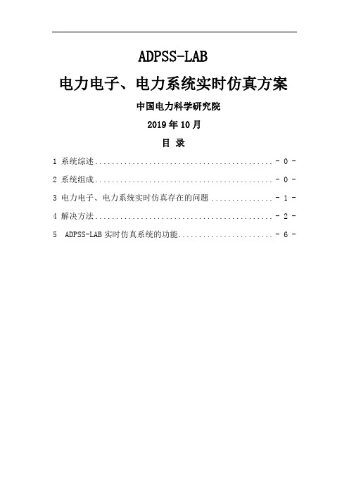
AD, 16-bits,500kS/s, +- 10V 16通道;
DA, 16-bits, 500kS/s, +-10V 16通道;
普通DO,转换速率5MHz,光电隔离, 5to28V,32通道;
普通DI,转换速率5MHz,光电隔离, 5to28V,32通道;
带时间戳TSDO,转换速率5MHz,光电隔离, 5to28V,32通道;
带时间戳TSDI,转换速率5MHz,光电隔离, 5to28V,32通道;
带时间戳的DIO主要用于PWM信号或事件信号的捕获和产生等功能。
图:实时仿真的硬件平台
3)实时PWM信号的捕捉和产生问题
电力电子、电力系统实时仿真的核心是如何精确的模拟高频开关器件的工作特性,以及这些器件工作时对电网的影响的问题。我们采取ADPSS-LAB提供的软件包来解决这些问题。
2)仿真的实时性问题
电力电子、电力系统往往在一个小范围内包含了十几个到几十个器件,相应的模型求解过程中包含了大量的矩阵计算(如:矩阵相乘,矩阵求逆等运算),如此大的计算量无法在给定的一个几十个微秒的仿真步长内由一个CPU结算出结果。因此,为了实现实时仿真的目标,必须将大的电力电子系统解耦成几个小的子系统,每个子系统分别运行在不同的CPU上,达到降低每个CPU的计算量,实现整个系统实时仿真的目的。
LabVolt系列电机器学习系统仿真软件(LVSIM-EMS)8970说明书

LabVolt Series DatasheetElectromechanical Systems Simulation Software (LVSIM ®-EMS)8970* The product images shown in this document are for illustration purposes; actual products may vary. Please refer to the Specifications section of each product/item for all details. Festo Didactic reserves the right to change product images and specifications at any time without notice.Festo Didactic en12/2023Electromechanical Systems Simulation Software (LVSIM®-EMS), LabVolt SeriesTable of ContentsGeneral Description_________________________________________________________________________________3 Virtual Instrumentation_____________________________________________________________________________4 Metering Window__________________________________________________________________________________5 Oscilloscope_______________________________________________________________________________________5 Phasor Analyzer____________________________________________________________________________________6 Harmonic Analyzer_________________________________________________________________________________6 Data Table and Graph Windows_______________________________________________________________________7 Software Protection and Licensing____________________________________________________________________7 Online Edition_____________________________________________________________________________________7 Computer Requirements_____________________________________________________________________________8 Topic Coverage_____________________________________________________________________________________8 Features & Benefits_________________________________________________________________________________8 List of Available Training Systems_____________________________________________________________________9 List of Manuals____________________________________________________________________________________9 Table of Contents of the Manual(s)____________________________________________________________________9Electromechanical Systems Simulation Software (LVSIM®-EMS), LabVolt Series••••••••General DescriptionThe Electromechanical Systems Simulation Software (LVSIM ®-EMS) is a simulation software that covers the same courseware as the following systems:Computer-Assisted 0.2 kW Electromechanical Training System, Model 8006-1DC and AC Power Circuits Training System, Model 8010-1Electromechanical Training System, Model 8010-9AC Power Transmission Training System, Model 8010-BAll workbooks parts of the systems above are available in the navigation menu of LVSIM-EMS for online consultation. To obtain the printing rights, Campus Licenses for each are available and must be ordered separately.With LVSIM-EMS, all the standard EMS laboratory equipment is replaced by images of the actual EMS modules that students can manipulate on the computer screen. Students can identify and set up equipment for a given exercise, make the necessary connections between the virtual EMS modules, and verify the connections made without the need for actual EMS equipment.Sophisticated mathematical models fully simulate the electrical and mechanical characteristics of all the actual EMS modules: power supplies, motors, generators, transformers, electrical and mechanical loads, etc. All modules simulated in the LVSIM-EMS software feature the same front panel information as the actual EMSmodules. Short-circuit connections in the virtual equipment setup cause the virtual circuit-breaker protection to trip. This trip condition is clearly indicated on the virtual EMS modules.Used either as a complement to the actual EMS laboratory equipment, or as a stand-alone product, LVSIM-EMS is a cost-effective tool that enables students to perform the same exercises as in the courseware of the above-mentioned training systems. When used as a stand-alone package, the LVSIM-EMS software allows students to perform hands-on activities related to electrical power and machines, including active, reactive, and apparent power, phasors, ac/dc motors and generators, three-phase circuits, and transformers.LVSIM-EMS is a web-browser based application available in three different configurations. The simulation software can either be installed locally on a Windows ® personal computer (local version), on a Windows server (network version), or accessed directly online through the website at (onlineversion). Both network and local versions are delivered with perpetual license for the current version. The online version is delivered as a annual license with possibility to expand for more years.Please visit https:// and try the online version!The LVSIM-EMS virtual equipment is so representative of the actual EMS laboratory equipment that it allows students to develop hands-on abilities as they would with actual equipment. It also allows students to prepare laboratories in advance by virtually making the connections required in the exercise, validating theirconnections, and finally saving and printing the setup. Such a preparation can significantly reduce laboratory time and the need for physical hardware. By combining stations using virtual equipment with stations using actual equipment, with students using each type alternately, it is possible to set up an electromechanical training station that maximizes cost-effectiveness.LVSIM-EMS simulates the following modules from the 8006-1, 8010-1, 8010-9, and 8010-B training systems:Capacitive Load, Model 8331Capacitor-Start Motor, Model 8251Data Acquisition Interface, Model 9062Data Acquisition and Control Interface, Model 9063Electromechanical Systems Simulation Software (LVSIM®-EMS), LabVolt Series•••••••••••••••••••••DC Motor/Generator, Model 8211Four-Pole Squirrel-Cage Induction Motor, Model 8221Four-Quadrant Dynamometer / Power Supply, Model 8960-2Full-Size Blank Module, Model 8160Half-Size Blank Module, Model 8161Inductive Load, Model 8321Lead-Acid Battery Pack, Model 8802Permanent-Magnet DC Motor, Model 8213Power Supply, Model 8821Power Supply, Model 8823Prime Mover / Dynamometer, Model 8960-1Regulating Autotransformer, Model 8349Resistive Load, Model 8311Single-Phase Transformer, Model 8341Synchronizing Module, Model 8621Synchronizing Module / Three-Phase Contactor, Model 8621-A Synchronous Motor/Generator, Model 8241Synchronous Motor/Generator with Thermistor Output, Model 8241-2 Three-Phase Transformer, Model 8348Three-Phase Transmission Line, Model 8329Universal Motor, Model 8254Make sure to select the right license type (8970 Series for local or network installations, 8972 Series for online access).Virtual InstrumentationLVSIM-EMS comprises a set of conventional and specialized instruments that can be used for measuring, observing, and analyzing electrical and mechanical parameters in electric power systems and power electronic circuits. Each instrument appears as a window on the computer screen. The conventional instruments include ac/dc voltmeters and ammeters, power meters, and an eight-channel oscilloscope. The specialized instruments include a six-channel phasor analyzer, a harmonic analyzer, torque, speed, and mechanical power meters, and user-programmable meters. The software is also provided with data-recording and graph-plotting capabilities. The various instruments are briefly described in the next section of this datasheet.Electromechanical Systems Simulation Software (LVSIM®-EMS), LabVolt SeriesMetering WindowThe Metering window displays up toeighteen meters, which can beconfigured individually for measuringac/dc voltage and current, electricalpower (active, reactive, and apparent),torque, speed, mechanical power, etc.The voltage and current meters haveseveral modes of operation that allowmeasurement of the mean (dc) value,RMS value, crest factor, RMS value of aparticular harmonic (up to the 15th value), RMS value of the harmonics, and total harmonic distortion (THD). Six of the eighteen meters are user-programmable and give access to a larger variety of functions for measurement of power factor, efficiency, impedance, frequency, energy, phase shift, etc. The layout of the meters in the Metering window is user-customizable.OscilloscopeThe Oscilloscope displays up to eightwaveforms simultaneously, each of adifferent color for easy identification.Each channel has independent verticalcontrols similar to those found onconventional oscilloscopes. Anautomatic scale-setting functionallows the sensitivity of each channelto be set automatically according tothe magnitude of the observedparameter. The time base and triggercontrols are similar to those found onmost oscilloscopes. The RMS value,average value, and frequency of eachobserved parameters can be displayed in the Oscilloscope window. Two vertical cursors can be activated to perform precise measurements at particular points on the displayed waveforms. The Oscilloscope toolbar includes two memory buttons for saving displayed waveforms.Electromechanical Systems Simulation Software (LVSIM®-EMS), LabVolt Series Phasor AnalyzerThe Phasor Analyzer displays thephasors related to the measuredvoltages and currents. The amplitudeand phase angle of each voltage andcurrent is clearly represented by theorientation and length of theircorresponding phasors, allowing easycomparison between the displayedparameters. This produces a uniqueand dynamic display of the voltagesand currents in a circuit (especially inthree-phase circuits) that cannot beobtained with conventionalinstruments. The RMS value, phase angle, and frequency of the voltage or current related to each phasor isdisplayed in the Phasor Analyzer window.Harmonic AnalyzerThe Harmonic Analyzer allowsobservation and analysis of theharmonic components in themeasured voltages and currents. Thefundamental frequency can bemanually set to the ac power networkfrequency or automatically set to thefrequency of the fundamentalcomponent of the selected voltage orcurrent. The harmonic components ofthe selected voltage or current can bedisplayed using a vertical scalegraduated in either absolute or relative values. A group of data displays in the Harmonic Analyzer indicates thevalues of the dc component of the selected voltage or current, as well as the total harmonic distortion (THD).Vertical and horizontal cursors can be displayed to perform precise measurements at particular points on the display. Since the equipment simulated by LVSIM-EMS produces only dc and sinusoidal ac signals (without harmonics), the Harmonic Analyzer, which is intended for use with devices that produce harmonics, is not oftenused with LVSIM-EMS.Electromechanical Systems Simulation Software (LVSIM®-EMS), LabVolt SeriesData Table and Graph WindowsThe values indicated by the variousmeters in the Metering window, aswell as values measured by the otherinstruments, can be recorded in theData Table window with a click of themouse. The values recorded in theData Table can be saved to a file(ASCII-formatted file). The recordeddata can also be used to plot graphsby selecting which parameter(s) toplot in the Graph window. This allowslab results to be plotted quickly andeasily. More sophisticated graphs canbe created by exporting the contentsof the Data Table window to anyspreadsheet program, such as Microsoft Excel®, directly through the Windows Clipboard.Software Protection and LicensingThe local and network version provides a perpetual licence and the online access version provides a annual licence (additional years can be purchased when ordering).The local and network version of LVSIM-EMS are copy-protected by means of a hardlock security device. When LVSIM-EMS detects the security device, students have complete access to all measuring functions of the virtual instruments and other protected features of LVSIM-EMS, as well as to the student manuals included with the simulation software. Note that students are allowed to copy the software onto their personal computer to allow them to prepare laboratories in advance.Two different security devices are available for LVSIM-EMS: a single-user hardlock key, which can be inserted in the USB port of the user's computer, and a multiple-user hardlock key, which can be inserted in the USB port of the network server or any computer in the same network. Once the hardlock key is active on the network, the other computer will see the available licences. Alternately, the multiple-user hardlock key can be inserted in a USB port inside the server using a circuit board with edge-type connector (provided with the key) that can be installed in a PCI expansion slot of the server.The multiple-user hardlock key can be installed in servers running under one of the following Microsoft®operating systems: Windows 7, Windows 8, Windows 10, Windows 2008 Server, and Windows 2013 Server. As its name indicates, the multiple-user hardlock key allows several users of a network to run LVSIM-EMS simultaneously. Different versions of LVSIM-EMS are available, each allowing a particular number of users.Online EditionThe online version of LVSIM-EMS is accessible directly via the internet, and requires no software installation nor any update since the latest version of the software is always available. The online version of LVSIM-EMS also includes a demo mode that allows students to prepare laboratories in advance by familiarizing with the equipment and connections. The demo mode does not require any login.Electromechanical Systems Simulation Software (LVSIM®-EMS), LabVolt Series••••••••••••••▪▪▪▪▪▪▪•••Topic CoverageFundamentals for Electric Power Technology Alternating CurrentCapacitors in AC Circuits Inductors in AC CircuitsPower, Phasors, and Impedance in AC Circuits Three-Phase CircuitsSpecial Transformer Connections Single- and three-Phase Transformers Fundamentals for Rotating Machines DC Motors and GeneratorsSpecial Characteristics of DC Motors AC Induction and Synchronous Motors Three-Phase Synchronous GeneratorsFeatures & BenefitsReplicates the Electromechanical Training System, enabling students to perform actual experiments using virtual equipment Install, move, and remove EMS modules in and from the workstation Modify module connections at any time and change the color of wires Install a timing belt between two EMS machines Verify module connections using a tool that highlights all wires connected to a same circuit point Perform measurements of voltage, current, power, speed, torque, impedance, resistance, reactance,and frequency and display the values on digital or analog meters Record measurements in a data table and plot graphs using the recorded data Display waveforms on a multi-channel oscilloscope and ac voltages and currents as phasors Students prepare for laboratories in advance using virtual equipment, thereby decreasing the time they require to perform the exercises using actual equipmentDecreases the quantity of actual equipment required per studentAllows students to practice with EMS equipment operation and connection at home on a personal computer••Computer RequirementsLocal and Network Versions:One (1) USB 2.0 port for the security dongle, Microsoft Windows 10 operating system recommended (compatible with Windows 7 and 8), basic dual core CPU, Google Chrome web browser installed (for better experience)Online Version:Microsoft Windows 10 operating system recommended (compatible with Windows 7 and 8 but not fully compatible with mobile devices), basic dual core CPU, internet access (bandwidth usage of 50 KB/s maximum), Google Chrome web browser installed (for better experience)Electromechanical Systems Simulation Software (LVSIM®-EMS), LabVolt Series••••List of Available Training SystemsQty Description Model number1Electromechanical Systems Simulation Software (LVSIM ®-EMS) - 1 User with USB Dongle ____ 586920 (8970-00)1Electromechanical Systems Simulation Software (LVSIM ®-EMS) - 5 Users with USB Dongles __ 586923 (8970-A0)1Electromechanical Systems Simulation Software (LVSIM ®-EMS) - 10 Users with USB Dongles _ 586926 (8970-B0)1Electromechanical Systems Simulation Software (LVSIM ®-EMS) - 15 Users with USB Dongles _ 586929 (8970-C0)1Electromechanical Systems Simulation Software (LVSIM ®-EMS) - 20 Users with USB Dongles _ 586932 (8970-D0)1Electromechanical Systems Simulation Software (LVSIM ®-EMS) - 25 Users with USB Dongles _ 586935 (8970-E0)1Electromechanical Systems Simulation Software (LVSIM ®-EMS) - 30 Users with USB Dongles _ 586938 (8970-F0)1Electromechanical Systems Simulation Software (LVSIM ®-EMS) - 35 Users with USB Dongles _ 586941 (8970-G0)1Electromechanical Systems Simulation Software (LVSIM ®-EMS) - 40 Users with USB Dongles _ 586944 (8970-H0)1Electromechanical Systems Simulation Software (LVSIM ®-EMS) - 5 Users Network __________ 586947 (8970-P0)1Electromechanical Systems Simulation Software (LVSIM ®-EMS) - 10 Users Network _________ 586950 (8970-Q0)1Electromechanical Systems Simulation Software (LVSIM ®-EMS) - 15 Users Network _________ 586953 (8970-R0)1Electromechanical Systems Simulation Software (LVSIM ®-EMS) - 20 Users Network _________ 586956 (8970-S0)1Electromechanical Systems Simulation Software (LVSIM ®-EMS) - 25 Users Network _________ 586959 (8970-T0)1Electromechanical Systems Simulation Software (LVSIM ®-EMS) - 30 Users Network _________ 586962 (8970-U0)1Electromechanical Systems Simulation Software (LVSIM ®-EMS) - 35 Users Network _________ 586965 (8970-V0)1Electromechanical Systems Simulation Software (LVSIM ®-EMS) - 40 Users Network ________ 586968 (8970-W0)1Electromechanical Systems Simulation Software (LVSIM ®-EMS) - 1 User Online, 1 year ______ 586971 (8972-00)1Electromechanical Systems Simulation Software (LVSIM ®-EMS) - 5 Users Online, 1 year _____ 586974 (8972-A0)1Electromechanical Systems Simulation Software (LVSIM ®-EMS) - 10 Users Online, 1 year ____ 586977 (8972-B0)1Electromechanical Systems Simulation Software (LVSIM ®-EMS) - 15 Users Online, 1 year ____ 586980 (8972-C0)1Electromechanical Systems Simulation Software (LVSIM ®-EMS) - 20 Users Online, 1 year ____ 586983 (8972-D0)1Electromechanical Systems Simulation Software (LVSIM ®-EMS) - 25 Users Online, 1 year ____ 586986 (8972-E0)1Electromechanical Systems Simulation Software (LVSIM ®-EMS) - 30 Users Online, 1 year ____ 586989 (8972-F0)1Electromechanical Systems Simulation Software (LVSIM ®-EMS) - 25 Users Online, 1 year ____ 586992 (8972-G0)1Electromechanical Systems Simulation Software (LVSIM ®-EMS) - 40 Users Online, 1 year ____ 586995 (8972-H0)List of ManualsDescriptionManual numberElectromechanical Systems Simulation Software (User Guide) ______________________________583879 (20858-E0)Computer-Based Instruments for EMS (User Guide) ______________________________________584396 (36221-E0)Table of Contents of the Manual(s)Electromechanical Systems Simulation Software (User Guide) (583879 (20858-E0))1 Overview of LVSIM-EMS2 Installing the Security Device3 Installing and Running LVSIM-EMS Computer-Based Instruments for EMS (User Guide) (584396 (36221-E0))1 Familiarization with the Metering Window and the Data TableElectromechanical Systems Simulation Software (LVSIM®-EMS), LabVolt Series••••2 Familiarization with the Oscilloscope3 Familiarization with the Phasor Analyzer4 Familiarization with the Harmonic Analyzer5 Measuring Three-Phase Power Using the Metering WindowElectromechanical Systems Simulation Software (LVSIM®-EMS), LabVolt SeriesReflecting the commitment of Festo Didactic to high quality standards in product, design, development, production, installation, and service, our manufacturing and distribution facility has received the ISO 9001 certification.Festo Didactic reserves the right to make product improvements at any time and without notice and is not responsible for typographical errors. Festo Didactic recognizes all product names used herein as trademarks or registered trademarks of their respective holders. © Festo Didactic Inc. 2023. All rights reserved.Festo Didactic SERechbergstrasse 373770 DenkendorfGermanyP. +49(0)711/3467-0F. +49(0)711/347-54-88500Festo Didactic Inc.607 Industrial Way WestEatontown, NJ 07724United StatesP. +1-732-938-2000F. +1-732-774-8573Festo Didactic Ltée/Ltd675 rue du CarboneQuébec QC G2N 2K7CanadaP. +1-418-849-1000F. +1-418-849-166611© Festo Didactic。
电网仿真装置简介及应用情况

1电网全数字实时仿真装置概述1.1电网全数字实时仿真装置简介电网全数字实时仿真装置,也称为电力系统全数字仿真装置(A dvanced D igital P ower S ystem S imulator,ADPSS),是由中国电力科学研究院研发的基于高性能PC机群的全数字仿真系统。
该仿真系统利用机群的多节点结构和高速本地通讯网络,采用网络并行计算技术对计算任务进行分解,并对进程进行实时和同步控制,实现了大规模复杂交直流电力系统机电暂态和电磁暂态的实时和超实时仿真以及外接物理装置试验。
利用该仿真系统,可以进行1000台机, 10000个以上节点的大系统交直流电力系统机电暂态仿真以及机电、电磁暂态混合仿真研究,可接入继电保护、安全自动装置、FACTS控制装置以及直流输电控制装置等实际物理装置进行闭环仿真试验,可接入MATLAB等商用软件进行局部和子任务计算,接入用户自定义模型以完成用户指定功能和任务。
图1-1、1-2、1-3分别为仿真系统外观图、硬件架构图和总体结构图。
图1-1仿真系统外观图图1-2仿真系统硬件架构图1-3仿真系统结构图仿真系统获授权发明专利3项——电力系统数字仿真装置、电力系统数字仿真方法、电力系统潮流分网并行计算,其中“电力系统数字仿真装置”获得中国专利优秀奖;获软件著作权一项。
仿真系统获2009年度国家科学技术进步一等奖。
专家鉴定认为:“成果具有自主知识产权,总体技术达到了国际领先水平。
”图1-4、1-5、1-6分别为仿真系统知识产权、鉴定及获奖情况。
图1-4 仿真系统专利及软件著作权图1-5 中国电机工程学会鉴定意见图1-6 仿真系统获2009年度国家科学技术进步一等奖1.2基于ADPSS用户开展工作情况ADPSS为研究大电网的稳定、事故分析、电网控制、新能源接入、特高压分析、高铁对电网的冲击、数字化变电站等等一切提供了平台和试验工具,为驾驭大电网安全提供了强有力手段。
2ADPSS应用案例2.1线路光纤电流差动保护试验采用典型输电系统模型进行线路光纤电流差动保护试验,试验系统如图9-1、图9-2所示。
ADPSS数字实时仿真技术发展

电流( A)
ADPSS ATP 25 20 15 10 5 0 -5 -10 -15 -20
0.16
0.18
0.2
0.22
0.24
0.26
0.28
0.3
时 间 t(s)
14
3. ADPSS新功能
3. ADPSS仿真模型库完善 – 多端柔直电磁模型 • 基于平均模型的换流器算法,能够较好地反映多端柔直 的系统级特性 • 已实现舟山5端柔直仿真建模
1. 机电-电磁混合仿真并行批量计算:针对方式专业的交直 流电网离线分析需求开发专用扫描工具,能够在暂稳数据 基础上自动生成混合仿真数据、利用单机/机群资源进行 串行/并行批量计算,提高方式计算效率。
技术特点: • 面向实际工程的直流输电电磁暂态模型库; • 直流电磁暂态模型初始工况自动调整和模型初始化; • 基于并行平台的混合仿真批量作业扫描; • 混合仿真故障集生成、电磁暂态仿真结果后处理。
23
ADPSS数字实时仿真技术发展
张星 中国电力科学研究院
2015年7月28日
1 ADPSS发展情况 2 ADPSS新功能 3 ADPSS典型应用
2
1 ADPSS发展情况
3
1. ADPSS发展情况
1998年 2006年 2009年
2013年
2015年
获国家科 技进步一 第一套仿 等奖 真系统投 项目预研 运 启动
20
3. ADPSS典型应用
2. 机网协调闭环试验技术 • 以ADPSS系统作为电网仿真核心,外接励磁/调速控制 器、汽机/水机/热工仿真系统或模型。
21
3. ADPSS典型应用
2. 机网协调闭环试验技术
电源侧:汽机、水机、热工仿真系统
电力系统仿真软件综述

Operator
actions LFC
Prime mover control
Protection
Generator control HVDC, FACTS,
etc.
Frequency variations
Tie-line regulation
Daily load variation
Long term dynamicsLong-duration
目前,国内常用的机电暂态仿真程序是电力系统综合程序(PSASP)和中国版BPA 电力系统分析程序。国际上常用的有美国PTI公司的PSS/E、美国EPRI的ETMSP 、ABB的SIMPOW程序、德国西门子的NETOMAC、德国Powerfactory的 DIgSILENT。
1.PSS/E
电力系统仿真软件综述
内 容
电力系统仿真概述 机电暂态仿真软件 电磁暂态仿真软件 电力电子仿真工具 配电网的仿真软件 实时物理仿真工具
一. 电力系统仿真概述
现代电力系统是集发电、输电、配电和用电为一体的复 杂非线性网络系统。对其物理本质的研究涉及到短至1μs 到长至1h的动态过程。为了保证实际运行的电力系统的 安全稳定性,不便采用在线物理试验的方法对电力系统的 动态行为进行研究。目前主要利用电力系统仿真软件离线 计算的方法对电力系统及装置的动态行为进行仿真研究。
根据需要研究的动态过程的作用时间长短,电力系统暂 态过程分为机电暂态过程和电磁暂态过程两大类。
根据仿真研究的对象,分为输电网和配电网仿真。
根据对元件描述的精细程度,分为集总元件仿真和分布 参数电磁场仿真。
电力仿真的时间尺
度
Electromagnetic transient modeling and simulation
电力系统仿真软件介绍(作业)
电力系统分析软件介绍1 EMTDC/PSCADEMTDC是一种世界各国广泛使用的电力系统仿真软件,PSCAD是其用户界面,一般直接将其称为PSCAD。
使得用户能更方便地使用EMTDC进行电力系统分析,使电力系统复杂部分可视化成为可能。
PSCAD/EMTDC基于dommel电磁暂态计算理论,适用于电力系统电磁暂态仿真。
EMTDC(Electro Magnetic Transient in DC System)即可以研究交直流电力系统问题,又能完成电力电子仿真及其非线性控制的多功能工具。
PSCAD由Manitoba HVDC research center开发。
2 PSAPACPSAPAC由美国EPRI开发,是一个全面分析电力系统静态和动态性能的软件工具。
其包含多个模块,其中部分模块可以单独使用。
模块和功能如下:DYNRED(Dynamic Reduction Program):网络化简与系统的动态等值,保留需要的节点。
LOADSYN(Load Synthesis Program):模拟静态负荷模型和动态负荷模型。
IPFLOW(Interactive Power Flow Program):采用快速分解法和牛顿-拉夫逊法相结合的潮流分析方法,由电压稳态分析工具和不同负荷、事故及发电调度的潮流条件构成。
TLIM(Transfer Limit Program):快速计算电力潮流和各种负荷、事故及发电调度的输电线的传输极限。
DIRECT:直接法稳定分析软件弥补了传统时域仿真工作量大、费时的缺陷,并且提供了计算稳定裕度的方法,增强了时域仿真的能力。
LTSP(Long Term Stability Program):LTSP是时域仿真程序,用来模拟大型电力系统受到扰动后的长期动态过程。
为了保证仿真的精确性,提供了详细的模型和方法。
VSTAB(V oltage Stability Program):该程序用来评价大型复杂电力系统的电压稳定性,给出接近于电压不稳定的信息和不稳定机理。
伟福LAB2000P系列 单片机仿真实验系统000
伟福®伟福Lab2000P系列单片机仿真实验系统使用说明书南京伟福实业有限公司® 伟福Lab2000P 单片机仿真实验系统 目录 - i -目录第一章 概述 (1)第二章 伟福实验系统组成和结构 (3)第三章 板上仿真器使用方法 (12)第四章 MCS51系列单片机实验 (19)MCS96系列单片机实验 (20)8088/86系列CPU 实验 (21)软件实验1. 存储器块清零(51/96/88) (22)2. 二进制到BCD 码转换(51/96/88) (23)3. 二进制到ASCII 码转换(51/96/88) (24)4. 内存块移动(51/96/88) (25)5. 程序跳转表(51/96/88) (26)6. 数据排序(51/96/88) (27)硬件实验1. P1口输入输出(51/96) (28)2. 继电器控制(51/96) (30)3. 用74LS245读入数据(51/96/88) (31)4. 用74LS273输出数据(51/96/88) (32)5. PWM 转换电压实验(51/96) (33)6. 音频控制(51/96) (34)7. 用8255输入、输出(51/96/88) (35)8. 串行数转换并行数(51/96) (36)9. 并行数转换串行数(51/96) (38)10. 计数器实验(51) (40)11. 外部中断实验(51/96) (41)12. 定时器实验(51/96) (43)13. D/A 转换实验(51/96/88) (45)14. A/D 转换实验(51/96/88) (47)15. 外部中断实验(急救车与交通灯) (51/96) (49)16. 八段数码管显示(51/96/88) (51)17. 键盘扫描显示实验(51/96/88) (53)18. 电子时钟(51/96/88) (55)19. 单片机串行口通讯实验(51/96) (57)® 伟福Lab2000P 单片机仿真实验系统 目录 - ii -20. 打印机控制实验(51/96/88) (59)21. 直流电机控制实验(51/96/88) (61)22. 步进电机控制实验(51/96/88) (63)23. 温度传感器实验(51/96/88) (66)24. 液晶显示屏控制实验(51/96/88) (67)25. 电子琴(51/96/88) (69)26. 空调温度控制实验(51/96/88) (71)27. 计算器实验(51/96/88) (74)28. 用HSO 方式输出PWM 波形(96) (76)29. 用HSI 方式测量脉冲宽度(96) (77)30. 用HSI 中断方式统计脉冲个数(96) (78)31. 计数器实验(96) (80).... 32. 用片内A/D 做A/D 转换实验(96).. (81)33. PWM 转换电压实验(88) (82)34. 8253计数器实验(88) (83)35. 8259外部中断实验(88) (84)36. 8253定时器实验(88) (86)37. 8251A 串行口通讯实验(88) (88)第五章 逻辑分析工具 (90)本实验说明书包括8051,80C196,8088/86三种实验说明(8051单片机有6个软件实验、27个硬件实验,80C196单片机有6个软件实验、31个硬件实验,8088/86CPU 有6个软件实验、21个硬件实验)。
SICElab赛思开放式综合实验 仿真系统 说明书
目 录产品简介0.1 系统组成 (1)0.2 实验内容 (5)0.3 实验方式 (5)0.4 支持器件 (5)实验平台1.1 实验模块 (6)1.2 常用逻辑门电路 (17)1.3 自由实验插座 (17)1.4 跳线器选择 (17)1.5 直流电源外引插座 (18)1.6 总线插孔 (18)1.7 空间分配 (18)G6W仿真器2.0 G6W/G6S型仿真器 (20)2.1 可配置仿真头 (21)2.2 G6W/G6S外形示意图 (21)2.3 POD8051仿真头 (22)2.4 POD89C52仿真头 (22)2.5 POD196KB/KC仿真头 (23)2.6 POD552仿真头 (24)2.7 POD16C5X仿真头 (25)G2K仿真板(选件)3.1 G2K仿真板与G2010实验平台的安装方法 (26)3.2 键盘使用说明 (27)3.3 键盘方式下的仿真方法 (30)软件安装WINDOWS平台的安装方法 (34)DOS平台的安装方法 (36)KEIL C51编译器的安装方法 (37)程序清单安装 (37)硬件安装j连接Lab8051CPU板 (38)j仿真器与实验平台的连接 (38)j仿真器与计算机的连接 (39)j实验连线 (39)实验例程(MCS51)第一节“验证式”实验例程实验一 拆字程序(键盘调试) (40)实验二 拼字程序(键盘调试) (47)实验三 数据区传递子程序(DOS平台) (48)实验四 数据排序实验(WINDOWS平台) (52)实验五 清零程序(模拟调试) (55)实验六 定时器/计数器(模拟调试) (57)实验七 中断系统(模拟调试) (58)实验八 串行口实验(模拟调试) (59)实验九 P1口输入、输出实验 (60)实验十 P3.0口输入、P1口输出实验 (62)实验十一 八段码管显示实验 (64)实验十二 键盘扫描显示实验 (66)实验十三 脉冲计数(定时/计数器记数功能实验) (69)实验十四 电子时钟(定时/计数器定时实验) (71)实验十五 INT0中断实验 (73)实验十六 A/D0809转换实验 (75)实验十七 D/A0832转换实验 (77)实验十八 电子琴 (79)实验十九 步进电机控制 (81)实验二十 数据存储器6264RAM实验 (86)实验二十一 EPROM固化及脱机运行 (87)实验二十二 逻辑分析仪在教学/实验中的利用 (88)第二节“模仿式”实验例程实验一 工业顺序控制(INTO INT1)综合实验 (91)实验二 扩展时钟系统(DS12887)实验 (93)实验三 双机通讯实验 (97)实验四 V/F压频转换实验 (99)实验五 力测量实验 (101)实验六 直流电机转速测量与控制实验 (104)实验七 点阵式LCD液晶显示屏实验 (108)实验八 温度测量实验 (116)实验九 微型打印机打印字符 (118)实验十 点阵LED广告屏实验 (120)实验十一 红外线遥控实验 (122)第三节“探索式”实验例程实验一 8031最小系统组成实验(AT89C51) (126)实验二 程序存储器扩展实验 (129)实验三 静态数据存储器扩展实验 (131)实验四 并行I/O口扩展实验 (134)实验五 串行口扩展并口实验 (137)实验六 多个外中断源扩展实验 (139)实验七 MCS51单片机与IBM微机通信 (141)实验八 8155接口芯片使用实验 (143)实验九 键盘、显示接口芯片8279使用实验 (147)实验十 8255控制交通灯实验 (150)实验十一 可编程计数/定时器8253实验 (153)实验十二 串行E2PROM93C46扩展实验 (155)实验十三 I2C总线E2PROM AT24C01扩展实验 (159)实验十四 AT89C2051控制步进电机 (161)实验十五 GAL16V8实验 (164)实验十六 译码器实验 (170)第四节“自检式”演示实验 (173)0 -- LCD液晶显示器实验1 -- V/F压力频率转换实验2 -- 脉冲计数实验3 -- DA0832转换实验4 -- AD0809转换实验5 -- 红外线遥控实验6 -- 温度测量实验7 -- 力测量实验8 -- 电子琴9 -- 直流电机转速测量与控制实验A -- 点阵LED广告屏实验B -- 步进电机控制C -- RS232通讯实验D -- 八段码管显示实验E -- 键盘扫描显示实验F -- 扩展时钟系统(DS12887)实验实验例程(MCS96)…………………………………………………………见MCS96分册实验例程(IN8086) ……………………………………………… 见8086/8088分册教师手册………………………………………………………………………………见分册自检测方法及维护方法问答集合MCS51 实验例程程序清单MCS96 实验例程程序清单8088 实验例程程序清单附:主要器件引脚图 G2010+实验平台原理图推荐资料: 《MCS51-51系列单片机实用接口技术》李华主编北京航空航天大学出版社《单片机的C语言应用程序设计》马忠梅等编著北京航空航天大学出版社《液晶显示应用技术》郭强等编著电子工业出版社《单片机原理及接口技术学习辅导》朱定华主编电子工业出版社产品简介随着社会对人才素质要求的不断提高,同时也随着国家对教育投入的不断加大,向学生提供高性能的实验/开发设备成为必要和可能。
04_ADPSS建模及仿真应用tips

举例:基于给定的一回直流模型,建立另一回直流模型,可批量将与原直流名称相关的标 识替换成待建直流模型的标识
编辑 更改元件名
批量替换元件名、 中间变量名
13
UDM加密
应用:在不影响案例计算的情况下,选择性地实现对二次系统 的保护
14
调试经验总结
3. 调试tips
15
机电-电磁混合仿真系统调试
小贴士
仿真结果不正确的可能原因: 1. 二次系统输入信号连接有误; 2. 二次系统输入信号处理有误。直接从ADPSS电磁暂态计算程 序一次电路输入的信号为标幺值,如二次系统是基于有名值建模 或虽然基于标幺值建模但基准与系统基准不同时,需进行转换
27
28
18
机电-电磁混合仿真系统调试
STEP3:无故障下,纯电磁暂态计算调试
– 调试方法:电磁网与机电网的边界母线接不含内阻抗的 电压源,线电压有效值和A相电压相角同该母线潮流数 据
– 要求:元件或模型输出变量曲线正常
19
机电-电磁混合仿真系统调试
STEP4:混合仿真参数配置检查
机电侧任务分配
电磁子网计算类型选 择“电磁暂态”
小贴士
脉冲分度(或时标) = 脉冲发生时刻距上一仿真时刻的时间 / 仿真步 长) RC缓冲电路参数选择方法:
1. R、C时间常数大于2倍的采样周期:R 2
2. 当器件截止时,流过RC的基波电流小于额定电流的0.1%:
C 1000 2
其中, 为变流器功率,VA; 为线电压,V;f为基波频率; 为采
样周期
牵引变电所 • 所建模型牵引变压器采用V/x接线
牵引网
• 牵引网供电方式有直接供电、BT(吸流变压器)供电、AT(自耦变压器) 供电、CC(同轴电缆)供电、带回流线的直接供电方式
电力系统仿真软件介绍(作业)

电力系统分析软件介绍1 EMTDC/PSCADEMTDC是一种世界各国广泛使用的电力系统仿真软件,PSCAD是其用户界面,一般直接将其称为PSCAD。
使得用户能更方便地使用EMTDC进行电力系统分析,使电力系统复杂部分可视化成为可能。
PSCAD/EMTDC基于dommel电磁暂态计算理论,适用于电力系统电磁暂态仿真。
EMTDC(Electro Magnetic Transient in DC System)即可以研究交直流电力系统问题,又能完成电力电子仿真及其非线性控制的多功能工具。
PSCAD由Manitoba HVDC research center开发。
2 PSAPACPSAPAC由美国EPRI开发,是一个全面分析电力系统静态和动态性能的软件工具。
其包含多个模块,其中部分模块可以单独使用。
模块和功能如下:DYNRED(Dynamic Reduction Program):网络化简与系统的动态等值,保留需要的节点。
LOADSYN(Load Synthesis Program):模拟静态负荷模型和动态负荷模型。
IPFLOW(Interactive Power Flow Program):采用快速分解法和牛顿-拉夫逊法相结合的潮流分析方法,由电压稳态分析工具和不同负荷、事故及发电调度的潮流条件构成。
TLIM(Transfer Limit Program):快速计算电力潮流和各种负荷、事故及发电调度的输电线的传输极限。
DIRECT:直接法稳定分析软件弥补了传统时域仿真工作量大、费时的缺陷,并且提供了计算稳定裕度的方法,增强了时域仿真的能力。
LTSP(Long Term Stability Program):LTSP是时域仿真程序,用来模拟大型电力系统受到扰动后的长期动态过程。
为了保证仿真的精确性,提供了详细的模型和方法。
VSTAB(V oltage Stability Program):该程序用来评价大型复杂电力系统的电压稳定性,给出接近于电压不稳定的信息和不稳定机理。
电力系统仿真技术介绍

电力系统实时仿真器主要有:ADPSS、ARENE、DDRTS、 HYPERSIM、RTDS、RT-LAB、dSPACE。 RTDS 全称为实时数字仿真仪,由加拿大曼尼托巴 RTDS 公司开发制造,是最早设计用于研究电力系统中电 磁暂态现象的装置。加拿大魁北克水电研究所的 TEQSIM 公司开发了电力系统实时仿真系统( HYPERSIM ),主要 用于电力系统电磁暂态仿真,其核心软件是 EMTP 程序。 法国电力公司( EDF )开发的 ANENE 实时仿真系统,其核 心软件也是 EMTP 。由殷图科技发展有限公司、东北电力 调度通信中心和清华大学联合研制、开发的数字动态实 时仿真系统(简称DDRTS),是国内自主研发的实时数字 仿真系统。中国电力科学研究院开发了世界上首套可模 拟大规模电力系统(1000台机、10000个节点)的全数字 实时仿真装置ADPSS,大规模电力系统的实时数字仿真也 得以实现。
不同软件仿真的适用范围并无严格定义,通常情况下同样的问题可以选用多种不同的软件进 行分析研究, 但选取适合的软件工具能够减少不必要的工作量。红色标注了使用频率高的软件。
4.1 机电暂态仿真软件
机电暂态过程的仿真,主要研究电力系统受到大扰动后的暂态稳定和 受到小扰动后的静态稳定性能。其中暂态稳定分析是研究电力系统受到诸 如短路故障,切除线路、发电机、负荷,发电机失去励磁或者冲击性负荷 等大扰动作用下,电力系统的动态行为和保持同步稳定运行的能力。 电力系统机电暂态仿真的算法是联立求解电力系统微分方程组和代数 方程组,以获得物理量的时域解。微分方程组的求解方法主要有隐式梯形 积分法、改进尤拉法、龙格-库塔法等,其中隐式梯形积分法由于数值稳定 性好而得到越来越多的应用。代数方程组的求解方法主要采用适于求解非 线性代数方程组的牛顿法。按照微分方程和代数方程的求解顺序可分为交 替解法和联立解法。 目前,国内常用的机电暂态仿真程序是电力系统综合程序(PSASP)和中 国版BPA电力系统分析程序。国际上常用的有美国PTI公司的PSS/E、美国 EPRI的ETMSP、ABB的SIMPOW程序、德国西门子的NETOMAC、德国 Powerfactory的DIgSILENT。
最新ADPSS-LAB实时仿真系统介绍汇总

A D P S S-L A B实时仿真系统介绍ADPSS-LAB电力电子、电力系统实时仿真方案中国电力科学研究院2012年10月目录1 系统综述................................................................................................................................... - 0 -2 系统组成................................................................................................................................... - 1 -3 电力电子、电力系统实时仿真存在的问题........................................................................... - 1 -4 解决方法................................................................................................................................... - 2 -5 ADPSS-LAB实时仿真系统的功能 ....................................................................................... - 8 -电力电子系统实时仿真方案1 系统综述实时仿真是研究电力电子、电力系统复杂的工作过程、优化系统与运行的重要手段。
电力电子、电力系统实时仿真经历了从第一代模拟分析系统,到第二代模拟/数字混合仿真系统,再到第三代数字实时仿真系统的发展过程。
ADPSS-LAB实时仿真系统介绍

ADPSS-LAB电力电子、电力系统实时仿真方案中国电力科学研究院2012年10月目录1 系统综述.................................................................................................................................. - 1 -2 系统组成.................................................................................................................................. - 2 -3 电力电子、电力系统实时仿真存在的问题.......................................................................... - 2 -4 解决方法.................................................................................................................................. - 3 -5 ADPSS-LAB实时仿真系统的功能..................................................................................... - 9 -电力电子系统实时仿真方案1 系统综述实时仿真是研究电力电子、电力系统复杂的工作过程、优化系统与运行的重要手段。
电力电子、电力系统实时仿真经历了从第一代模拟分析系统,到第二代模拟/数字混合仿真系统,再到第三代数字实时仿真系统的发展过程。
ADPSS-LAB正是第三代数字实时仿真系统的代表产品。
面向未来电力的ADPSS融合仿真

融合仿真的概况
6
ADPSS®72ADPSS的融合仿真技术
8
ADPSS融合仿真技术的技术方案
通用仿 真软件 电网设 备模型
分析控 制功能
ADPSS
®
跨领域 仿真
9
9
ADPSS融合仿真技术的技术方案
参与系统矩阵 修改的紧耦合 融合仿真 多软件之间的引擎级融 合仿真 HLA信号级互联融合方案
C++用户接口方案
If you dream it, you simulate it[1].
通过引入可视化编程为基础的交互模式, 提供用户广阔的创造力空间。各种领域的 模型和工具的融合,真正创造无限可能。 我们开发团队回归电力系统仿真软件的本 质,从模型算法,并行仿真和平台融合三 个方面发力,贡献给客户最具想象力的产 品。
DLL外接库连接方案
10
ADPSS融合仿真技术的技术方案
DLL
External Function Equvilent Block UDM 1
.cpp, .c
11
ADPSS融合仿真技术的技术方案
Init
创新、创造
Step
注入电流源 系统矩阵 开关标志位
+ +
元件初始化API: I0%sinit(I0* dI0); Gy%sinit(Gac* yGac); 元件运行API: I0%supdate(I0* dI0); Gy%supdate(Gac* yGac); GFlag%supdate(Gac* yGac); 元件结束API: %sterminate();
面向未来电力的ADPSS融合仿真
——ADPSS仿真的开发者集成环境
穆清 博士
Contents
ADPSS-LAB实时仿真系统介绍共9页文档
ADPSS-LAB电力电子、电力系统实时仿真方案中国电力科学研究院2019年10月目录1 系统综述........................................... - 0 -2 系统组成........................................... - 0 -3 电力电子、电力系统实时仿真存在的问题............... - 1 -4 解决方法........................................... - 2 -5 ADPSS-LAB实时仿真系统的功能....................... -6 -电力电子系统实时仿真方案1 系统综述实时仿真是研究电力电子、电力系统复杂的工作过程、优化系统与运行的重要手段。
电力电子、电力系统实时仿真经历了从第一代模拟分析系统,到第二代模拟/数字混合仿真系统,再到第三代数字实时仿真系统的发展过程。
ADPSS-LAB正是第三代数字实时仿真系统的代表产品。
ADPSS-LAB是一种基于并行计算技术、采用模块化设计的电力电子、电力系统实时仿真系统。
它既可以在普通PC机上进行离线仿真,也可通过并行计算机与实际的电力电子器件联接而进行实时在线仿真。
与前两代仿真系统相比,ADPSS-LAB具有以下优势:1)既可以对电力电子、电力系统机电和电磁暂态分别进行实时仿真,同时也可以对机电和电磁暂态混合系统进行实时仿真。
2)仿真精度高;ADPSS-LAB在实时仿真过程中采用32位双精度浮点数运算,其仿真的精度与公认的离线分析软件MATLAB的仿真精度相当。
3)良好的升级和扩充性;ADPSS-LAB由于直接采用商用的基于PC Cluster的连接方式,当仿真的系统规模增大时,只需增加CPU数目和增大内存容量即可,从系统的升级和扩展灵活性等方面有很好的发展前景。
2 系统组成软件部分:实时操作系统:QNX建模软件:MATLAB/simulink,SimPowerSystem电力电子、电力系统实时仿真包电力电子模型库硬件部分:并行处理系统(12-core INTEL CPU)I/O接口模块信号调理模块3 电力电子、电力系统实时仿真存在的问题1)建模的问题仿真系统能够提供友好的图形用户界面,丰富的电力电子、电力系统元件库且模型精度满足仿真要求,同时还要允许用户方便的添加自己的模型。
LabX Laboratory Software 产品介绍说明书

LabXPower the BenchLabX Laboratory Software Efficient Workflows One SystemMaximum SecurityL a b o r a t o r y S o f t w a r e2One SystemHaving one common software forall instruments brings a variety ofadvantages, including:• Centralized management• Less complexity• Less training• Fewer validation costs• Data exchange• Avoid transcription errors• One single interface to otherlab systemsMaximum SecurityLabX fully supports the currentrequirements of regulatorybodies. Security features such aselectronic signatures and anAudit Trail makes your labsystem audit-ready at any time.• Audit Trail• Electronic Signatures• User RightsOneSoftwareforAllLabX Laboratory Software connects to multiple METTLER TOLEDOlab instruments. Benefit from increased workflow efficiency,optimal security support and centralized management of oneor multiple instruments, users and data.LabX is not just a connection to an instrument, it is a complete laboratory solution.There is no need for PCs in the laboratory, the system works remotely via the network.LabX automates all administrative work. The paperless lab is a reality.LabX makes your laboratory lean and provides highest security.LabXLaboratory Instrument SoftwareEfficient WorkflowsSimplify your daily routines bothin the lab and in the office withLabX software. Secure yourprocesses and SOPs and makesure they are properly followedby having the right information atyour fingertips.• Easy application development• Automatic generation andrecalculation of results• Reports• User guidance at theinstrument3 InstrumentsDensity MetersRefractometersUV/VIS SpectrophotometersTitratorsKarl Fischer TitratorspH MetersBalancesMelting Point DevicesAutomated Quantos Dosing SystemsAutomated Sample Changers4Are your instruments and your sensors in the right condition for analysis? Are all tasks planned properly?• Set-up the daily task list and assign tasks to users • Define analysis in external systems and send to LabX • Automatic recognition of expired sensors and other equipment• Automatic blocking of instruments outside of specifications• Automatic tests, adjustments and calibrations ofinstruments and sensorsAre you using the appropriate SOP? Did you follow the SOP correctly? Did you choose the right instrument?• Create user-specific shortcuts• Automatic check of correct instrument specifications • Intuitive user guidance at the instrument touchscreen • Fully automated multiparameter measurementsE f fi c i e n t W o r k fl o w sDaily routines both in the lab and in the office are greatly simplifiedthanks to the power of LabX. You can rest assured that SOPs are followed, processes are secure, and all the information you need is at your fingertips.Optimize your complete laboratory workflow with LabX − from sample data entry to measurements, reporting and data export or integrate it fully into your LIMS, LES or any other system. You can work at the instrument touchscreen, at the PC or both concurrently – whatever fits your needs best.LabX Workflow SupportOptimize Your Processes with LabXHave you thought about the analysis workflow? Do you have all the information and sample data ready?• Develop and implement SOP-compliant application methods, ready for use on the relevant instrument • Define the rights of individual users and set-up the daily task list• Prepare sample data and measurements in external systems (e.g. LIMS) and send the data to LabXPlanningPreparationExecutionAre the results within specifications? Have you recalculated correctly? Do you have the complete data?• Real-time storage of all data and metadata• Automated calculations• Automated evaluationof results according to predefined specifications (out-of-spec results are highlighted)• Forwarding of evaluated data to LIMS and other external systems Have you recorded andcompiled all data clearlyand correctly?• Automated and centralizedresult documentation throughLabX• Possibility to view andreview complete data andmetadata at all times• User-defined reports• Network printing or reportstorage as customized file(e.g. pdf, xml, csv)Is your system audit-readyat all times? Did you signyour work? Can you find allmetadata in time?• Audit trail with customizedsearch folders• Single/double electronicsignature processes• Secure database• Single database with alldata and metadata of allconnected instrumentsAnalysis & Data Management Reporting & Archiving Audit56With LabX as a single solution for METTLER TOLEDO lab instruments you can reduce complexity while improving processes and data quality in your lab. The benefits of such a system are efficient and safe data handling, high process security and full SOP user guidance at the instrument terminal without the need of a PC next to each instrument.Once an SOP has been converted into a LabX workflow it will be available on each relevant device and guide the user automatically. All the collected measurement data, raw data and contextual metadata is stored automatically in the central database. Data can be exchanged safely. Manual data transfer is no longer necessary, thus eliminating potential transcription errors. With the ability to generate automatic reports, time-consuming administrative work is reduced to a minimum. The operator can concentrate on executing the actual analysis effectively, achieving the best possible results.One SystemFor Multiple InstrumentsO n e S y s t e mLean IntegrationMuch more than just data import and export. Save time and avoid transcription errors by integrating METTLER TOLEDO labinstruments to external systems such as ELN, LIMS, SAP and Excel with LabX.• Exchange of csv or xml files • Integrated APICentralized Management One software which is able to create one system with a variety of instruments allows you to manage everything:• Connected instruments• Resources used in the system • Workflows over various instruments• Data and metadata generated in this system• Users and user rightsLims Lab1Lab27“LabX makes your lab paperless and lean and providesmaximum security.”/labx8To ensure the quality of the data generated in a laboratory, data integrity is key in current Good Manufacturing Practices (cGMP).In the event of an inspection it must be ensured that all analytical data is accurate, complete and consistent.LabX has all the technical controls in place to support laboratories around the globe with regulatory compliance. The FDA ALCOA+ requirements for data integrity are fully supported. Keep your system secured with the LabX validation products and services offered by METTLER TOLEDO and be ready for an audit at any time.Ensure System Securityand Audit-Readiness at All TimesM a x i m u m S e c u r i tyValidation SupportPredefined validation manuals ensure validation of all critical aspects and assist withcompliance procedures. The total cost of ownership is significantly reduced by validating one system for many instruments.• Ready-to-use Validation Manuals• Less total cost of ownershipRegulatory SupportBuilt-in security features such as electronic signatures and user management options assist you in complying with regulations and ensure your lab is audit-ready at all times.• Secure database, full traceability • Audit Trail• Management of instrument tests• User rights• Review/approve data9Tailored ServicesOur trained and experienced technical specialists will support you in anything you require to keep your system compliant and running at peak performance.• Maintenance contracts • Professional installation • Validation service • On site trainings• Application development • Support & maintenance10LabX is fully adaptable to meet your needs. Connect the instruments you want in a simple or a distributed system. A range of options allows you to choose extra functionalities to match your requirements.You can either install LabX on one PC or on one or several servers in a network. Connect one or several instruments to one LabX system and add extra functionalities as you need them.Tailor LabX to Your Needs Start Small, Expand LaterS t a r t S m a l l , E x p a n d L a t erFull Network SolutionProfit from full LabX functionality throughout your company network. Access all methods from several labs and collect data in a lean and secure way.• Work in the office or in the lab • Connect several labs to one LabX systemExpansion at Any TimeExtend your LabX installation with extra options, such as user management or regulation sup-port according to your needs.• Extend the functionality with various options• Connect up to 30 instrumentsBasic Installation Profit from extendedfunctionalities in workflowguidance and data management for your instrument.• Installed on one PC• Connect up to 3 instruments11Options• User Management• Import/Export• Integration• Statistical Evaluation• Advanced Report Designer • RegulationFor more information Explore the benefits of LabX /labxVisit our website to see whatLabX laboratory software canbring to your lab – on the labbench and in the office LabX Laboratory Software One System to Simplify Your Lab LabX Power the BenchMETTLER TOLEDO GroupLaboratory WeighingLocal contact: /contactsSubject to technical changes© 07/2017 METTLER TOLEDO. All rights reserved 30427583Global MarCom 2181 LB/MD。
电力系统ADPSS仿真系统方案

电力系统ADPSS仿真系统方案目录1.项目背景 (3)2.技术原理 (3)3.ADPSS仿真系统结构 (4)3.1仿真集群 (5)3.1.1 仿真机群 (5)3.1.2 终端工作站(工作台) (5)3.1.3 通信系统 (6)3.1.4 操作系统 (6)3.2信号输出部分 (6)3.2.1 物理接口箱 (6)3.2.2 功率放大器 (7)3.2.3 继电保护及自动控制装置综合试验台 (7)3.2辅助设备 (7)4. ADPSS仿真系统的功能 (7)4.1电网分析计算 (8)4.2电力系统故障的再现和分析 (8)4.3装置的检验和试验研究 (8)4.4电网控制系统控制策略的验证研究 (9)1.项目背景“十三五”期间,国家电网负荷需求急剧增长、电源装机也逐年增加。
同时, 1000kV特高压线路、智能变电站相继投运,电网中各种安全自动装置使得电网的运行控制变得十分复杂。
电力工作人员在电力系统仿真装置的研究过程中,力求利用先进的仿真手段和装置,为国家电网的运行、分析、控制等提供优质的技术支持和解决方案。
电力工作人员希望通过全数字实时仿真装置,提高电网稳定分析能力,以及准确地掌握整个管辖区域内电力系统的运行状况,特别是在操作、扰动和故障情况下系统的动态和暂态运行行为。
2.技术原理电力系统全数字实时仿真装置(ADPSS)由中国电力科学研究院研发,基于高性能微机机群的电力系统全数字仿真系统。
该仿真系统利用机群已有的多节点结构,以及其高速的通讯网络,采用并行计算技术对电力系统模拟任务进行分解。
ADPSS仿真系统利用进程实时同步控制,实现了复杂交直流电力系统的大规模机电暂态、电磁暂态的实时仿真,并且利用接口装置对外接物理装置进行试验。
该仿真系统的仿真规模可达到1000台发电机、超过10000节点。
同时该仿真系统可以与调度自动化系统相连,以取得在线调度数据进行仿真。
也可接入继电保护、安全稳控装置、柔性交流输电控制装置以及直流输电控制装置等,进行闭环仿真试验研究。
- 1、下载文档前请自行甄别文档内容的完整性,平台不提供额外的编辑、内容补充、找答案等附加服务。
- 2、"仅部分预览"的文档,不可在线预览部分如存在完整性等问题,可反馈申请退款(可完整预览的文档不适用该条件!)。
- 3、如文档侵犯您的权益,请联系客服反馈,我们会尽快为您处理(人工客服工作时间:9:00-18:30)。
ADPSS-LAB电力电子、电力系统实时仿真方案中国电力科学研究院2012年10月目录1 系统综述................................................ - 0 -2 系统组成................................................ - 0 -3 电力电子、电力系统实时仿真存在的问题.................... - 1 -4 解决方法................................................ - 2 -5 ADPSS-LAB实时仿真系统的功能........................... -6 -电力电子系统实时仿真方案1 系统综述实时仿真是研究电力电子、电力系统复杂的工作过程、优化系统与运行的重要手段。
电力电子、电力系统实时仿真经历了从第一代模拟分析系统,到第二代模拟/数字混合仿真系统,再到第三代数字实时仿真系统的发展过程。
ADPSS-LAB正是第三代数字实时仿真系统的代表产品。
ADPSS-LAB是一种基于并行计算技术、采用模块化设计的电力电子、电力系统实时仿真系统。
它既可以在普通PC机上进行离线仿真,也可通过并行计算机与实际的电力电子器件联接而进行实时在线仿真。
与前两代仿真系统相比,ADPSS-LAB具有以下优势:1)既可以对电力电子、电力系统机电和电磁暂态分别进行实时仿真,同时也可以对机电和电磁暂态混合系统进行实时仿真。
2)仿真精度高;ADPSS-LAB在实时仿真过程中采用32位双精度浮点数运算,其仿真的精度与公认的离线分析软件MATLAB的仿真精度相当。
3)良好的升级和扩充性;ADPSS-LAB由于直接采用商用的基于PC Cluster的连接方式,当仿真的系统规模增大时,只需增加CPU数目和增大内存容量即可,从系统的升级和扩展灵活性等方面有很好的发展前景。
2 系统组成软件部分:➢实时操作系统:QNX➢建模软件:MATLAB/simulink,SimPowerSystem➢电力电子、电力系统实时仿真包➢电力电子模型库硬件部分:➢并行处理系统 (12-core INTEL CPU)➢I/O接口模块➢信号调理模块3 电力电子、电力系统实时仿真存在的问题1)建模的问题仿真系统能够提供友好的图形用户界面,丰富的电力电子、电力系统元件库且模型精度满足仿真要求,同时还要允许用户方便的添加自己的模型。
2)仿真的实时性问题电力电子、电力系统往往在一个小范围内包含了十几个到几十个器件,相应的模型求解过程中包含了大量的矩阵计算(如:矩阵相乘,矩阵求逆等运算),如此大的计算量无法在给定的一个几十个微秒的仿真步长内由一个CPU结算出结果。
因此,为了实现实时仿真的目标,必须将大的电力电子系统解耦成几个小的子系统,每个子系统分别运行在不同的CPU上,达到降低每个CPU的计算量,实现整个系统实时仿真的目的。
3)实时PWM信号的捕捉和产生问题由于电力电子、电力系统中大量的采用高频电力电子器件,由此给实时仿真带来许多前所未有的问题。
比如:如何准确的捕捉PWM信号?如何准确的产生高频PWM信号?如何设计合理的控制策略实现误差补偿等问题。
4)系统的升级和扩展问题整个系统要具有良好的维护和升级扩展性,且维护和升级成本低廉。
系统应采用COTS货架式产品和通用的总线标准,用户对设备提供商的依赖度低,便于用户后续的升级和扩展要求。
4 解决方法针对以上问题,我们分别采用以下的方法来解决。
1)建模的问题模型开发工具采用MATLAB/Simulink和SimPowerSystem软件包。
这两个软件包一方面提供了友好的图形用户界面,用户只需通过鼠标操作即可完成整个建模工作;另一方面两个软件包提供了丰富的电力电子、电力元件模型库,用户可以方便的利用这些模型搭建出各种复杂结构的电力电子、电力系统模型。
另外,用户还可以将C代码编写的模型集成到仿真系统中。
ADPSS-LAB还提供了专门针对实时仿真的电力电子、电力模型库,做为对SimPowerSystem元件库的补充。
当安装好ADPSS-LAB软件后,这些模型库被自动的添加到Simulink软件中。
ADPSS-LAB提供的模型库包括:➢带时间戳的整流电路模型;➢带时间戳的逆变器模型;➢电力电子元器件模型库;➢实时逻辑处理模型库;➢事件产生信号模型库等。
2)仿真的实时性问题对电力电子、电力系统的实时仿真问题,我们分别从软件和硬件两方面入手解决该问题。
软件方面:通过将一个大的电力电子、电力系统模型分解成多个子系统,不同的子系统算由不同的CPU单元完成计算,从而大大减小了每个CPU 单元的计算任务,缩短了整个系统的计算时间,提高了实时性;不同的CPU 单元间在每个步长内根据信号传递关系交换数据。
硬件方面:通过采用并行处理系统,为实时仿真提供相应的硬件平台。
考虑到电力电子、电力系统的具体情况:一个区域通常大约有十几个或几十个电力电子、电力器件,所以推荐采用包含12个CPU core的并行处理系统,整个系统的实时仿真的步长最小可以达到20us左右。
并行计算机通过FPGA卡控制IO接口机。
IO接口机本身带有AD,DA,DIO等IO模块,通过这些IO模块与实际设备相连。
IO模块的性能指标如下:✓AD, 16-bits, 500kS/s, +- 10V 16通道;✓DA, 16-bits, 500kS/s, +-10V 16通道;✓普通DO,转换速率5MHz, 光电隔离, 5 to 28V, 32通道;✓普通DI,转换速率5MHz, 光电隔离, 5 to 28V, 32通道;✓带时间戳TSDO, 转换速率5MHz, 光电隔离, 5 to 28V, 32通道;✓带时间戳TSDI, 转换速率5MHz, 光电隔离, 5 to 28V, 32通道;带时间戳的DIO主要用于PWM信号或事件信号的捕获和产生等功能。
图:实时仿真的硬件平台3)实时PWM信号的捕捉和产生问题电力电子、电力系统实时仿真的核心是如何精确的模拟高频开关器件的工作特性,以及这些器件工作时对电网的影响的问题。
我们采取ADPSS-LAB提供的软件包来解决这些问题。
(一)RTE blockset:PWM信号处理工具包该软件包主要用来处理PWM开关信号,其主要功能有两个:➢实时产生开关事件(如:PWM信号,编码信号等)➢与FPGA卡配合,实时捕捉采样间隔之间的触发脉冲,记录脉冲产生的时间以及逻辑状态的改变情况,然后在模型的计算过程中进行补偿,达到提高实时仿真精度的目的。
PWM信号处理工具包针对电力电子元件提供了许多专业处理模块。
软件安装时会自动在MATLAB/Simulink目录下添加所有的处理模块,这些模块包括:用于实时仿真的逆变器模型,整流器模型,实时逻辑处理模型库,产生事件信号模型库等。
PWM信号处理工具包的工作原理如下图所示。
当需要产生PWM信号时,利用工具包提供的模块可以产生出包含时间和状态的PWM信号,特别是介于两个相邻采样间隔之间的PWM信号。
产生出来的PWM信号通过FPGA卡上的TSDO模块输出。
当需要从外部捕获PWM信号时,PWM信号通过FPGA卡上的TSDI 模块输入。
FPGA卡可以做到很高的采样频率(如100MHz),FPGA 卡作为事件发生记录仪,在仿真运行过程中,实时捕获输入的PWM 信号,记录PWM信号产生的时间以及逻辑状态的改变情况,然后在模型的计算过程中进行补偿,达到提高实时仿真精度的目的,其工作原理如下图所示。
4)系统的升级和扩展问题传统的电力系统实时仿真装置是由原厂商提供非标化的软件、硬件和运行平台。
用户购买后,后续的系统维护、升级完全依赖原厂商。
实时仿真装置超过一年的质保期后,每年都需要向原厂商支付高额的费用购买系统的技术支持和软件升级。
用户在使用中如果需要原厂商增加额外的功能或开放系统的部分接口,都需要与原厂商进行协商,付出高额的时间和费用,用户完全处于被动服从的地位。
ADPSS-LAB系统采用通用的多核服务器结构,支持标准的PCI 或cPCI总线结构,用户可以灵活的对系统进行升级和扩展。
当实时仿真的电力电子系统规模增大时,只需增加多核服务器或IO接口机的数目即可实现扩大系统仿真规模的目的。
5 ADPSS-LAB实时仿真系统的功能1)电力电子、电力系统电磁暂态仿真ADPSS-LAB可完整的模拟包括:电机、传输网络以及控制系统的电力电子、电力系统,可计算电力电子、电力系统的电磁暂态问题。
可模拟系统的不同运行和干扰状况,包括各种短路故障等。
2)电力电子、电力系统闭环实时测试ADPSS-LAB系统通过高速IO接口机同外部设备相连,可进行系统的实时闭环测试。
ADPSS-LAB对电力电子、电力系统进行实时闭环测试的原理如下图所示。
借助该功能,ADPSS-LAB可以方便地实现评估电力系统的功能以及测试电力电子系统性能的目的。
3)控制系统仿真使用ADPSS-LAB系统可以方便的创建各种开环和闭环控制器,进行控制系统的仿真研究。
所有取自电力电子器件和电机的变量都可作为控制器的输入;另外,其它控制器的信号量也可作为控制器的输入。
同时,这些控制器的输出以电压、电流、阻抗和功率的形式作用于系统,所有控制模块的输入信号量及输出信号量都可绘制出来。
总之,与传统的电力实时仿真器相比,ADPSS-LAB系统提供了实时仿真的准确性、并行处理的强大计算能力以及离线仿真的灵活性,比传统的模拟仿真器更加灵活、简单、廉价,满足电力电子、电力系统实时仿真的要求。
希望以上资料对你有所帮助,附励志名言3条:1、生气,就是拿别人的过错来惩罚自己。
原谅别人,就是善待自己。
2、未必钱多乐便多,财多累己招烦恼。
清贫乐道真自在,无牵无挂乐逍遥。
3、处事不必求功,无过便是功。
为人不必感德,无怨便是德。