台湾大毅1206合金大功率电阻RLM12系列选型手册
大品牌采样电阻,台产大毅品牌合金电阻
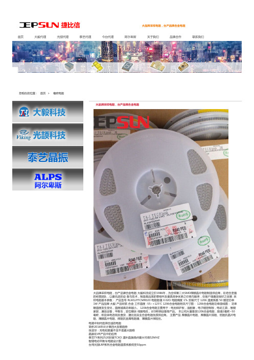
大品牌采样电阻,台产品牌合金电阻首页大毅代理光颉代理泰艺代理今台代理阿尔卑斯关于我们品牌合作联系我们大品牌采样电阻,台产品牌合金电阻大品牌采样电阻,台产品牌合金电阻 大毅科技成立於1986年,为全球第二大SMD厚膜晶片电阻制造供应商,在结合坚强的经营团队,以最先进的设 备与技术,制造高品质的零组件及最具竞争优势之价格与服务,在客户端奠定良好之信誉. 采样电阻基本参数: 产品型号 RLM12FTCMR020 电阻阻值 0.02Ω 电阻精度 1% 封装尺寸 1206 温度系数 50 额定功率1W 产品品牌 大毅 产品材质 合金 工作温度 -55~+125℃ 1206合金电阻相关尺寸图: 1206合金电阻功率曲线图: 功率随温度发生变化,温度越高功率越小。
1206合金电阻主要用于:电池保护板,适配器,电子烟控制板,电动工具,智能家居,通信设备,平衡车,定位模块 伺服电机,LED照明设备等产品。
本公司大量备货1206合金电阻,阻值1毫欧~50毫欧,欢迎来电咨询及查货,捷比信实业合金电阻优质供应商。
主要产品 厚膜晶片电阻、厚膜晶片排阻、低阻抗晶片电阻、薄膜晶片电阻、微阻抗金属电阻器、薄膜晶片保险丝。
电路中如何选择合适的电阻简析2016年云计算四大发展趋势张进华:充电桩数量不足不是最大阻碍晶振在VR产品中的应用泰艺TY系列2520封装TCXO 温补晶振频点最大可做52MHZ智能电动平衡车电路设计图台湾光颉LRP系列合金电阻温漂系数低至50ppm满足航空应用对电阻性能的新需求您现在的位置:首页 >毫欧电阻满足航空应用对电阻性能的新需求光颉0201*4贴片排阻军标级电阻 0.01%精密电阻 万分之一精度电阻 薄膜精密电阻精密电阻 合金电阻 大功率电阻 采样电阻 毫欧电阻 台湾大毅 台湾光颉 产品中心 联系方式 品牌合作 Kingbright代理 今台代理知识版权所有 Copyright © All RIGHTS RESERVED. 网站统计。
LR1206-21R050F4系列规格书贴片合金电阻推荐

0.074±0.010 (1.880±0.254) 0.044±0.010 (1.118±0.254) 0.079±0.010 (2.02±0.254) 0.074±0.010 (1.880±0.254) 0.044±0.010 (1.118±0.254) 0.066±0.010 (1.676±0.254) 0.044±0.010 (1.118±0.254) 0.085±0.010 (2.159±0.254) 0.071±0.010 (1.803±0.254)
自行注意版本更新
註
非經允許,禁止自行影印文件
60 Series No.
RALEC
旺詮
LR 金屬板微電阻規格標準書
4 尺寸及構造
1206 / 2010 / 2512 / 2725 / 2728
L
文件編號 版本日期 頁次
IE-SP-060 2015/07/01
4/19
4527 / 4527S
L
W H
T1
T2
0.038±0.010 (0.965±0.254) 0.038±0.010 (0.965±0.254)
備
非發行管制文件
發行管制章 DATA Center.
自行注意版本更新
註
非經允許,禁止自行影印文件
60 Series No.
RALEC
旺詮
LR 金屬板微電阻規格標準書
文件編號 版本日期 頁次
4.1 合金板材料:
7.0~50.0 --
7.0~49 7.0~50
0.3~50.0 0.3~1.0 0.5~100 0.3~100
LR2512
0.3mΩ: ≦±150
大毅合金电阻规格书-RLP系列
High Temperature Exposure
IEC60115-1- 4.23.2
JIS-C5201-4.23.2
170℃, 1000hrs
< ±1%
Low Temperature Storage
EC60115-1- 4.23.4
JIS-C5201-4.23.4
-55℃, 1000hrs
Moisture no Load
Reference
standard
IEC60115-1-4.8
JIS-C5201-4.8
IEC60115-1-4.25.1
JIS-C5201-4.25.1
Condition of Test
+25℃ ~ +125℃
Test Limits
Refer 4.0
1000hours at rated power, 70℃,
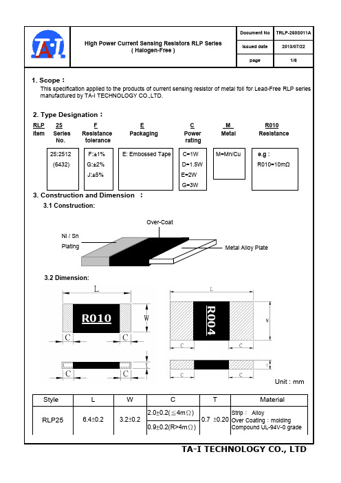
3.2 Dimension:
R004
R010
Unit : mm
Style
L
W
C
T
Material
2.0±0.2(≦4mΩ)
RLP25
6.4±0.2
3.2±0.2
Strip: Alloy
0.7 ±0.20 Over Coating:molding
0.9±0.2(R>4mΩ)
Compound UL-94V-0 grade
< ±1%
1.5hours “ON”, 0.5hour “OFF”
IEC60115-1-4.13
JIS-C5201-4.13
5 X rated power for 5s
< ±0.5%
IEC60115-1- 4.24.2.1a)
台湾天二大阻值合金采样电阻TGL系列选型规格书
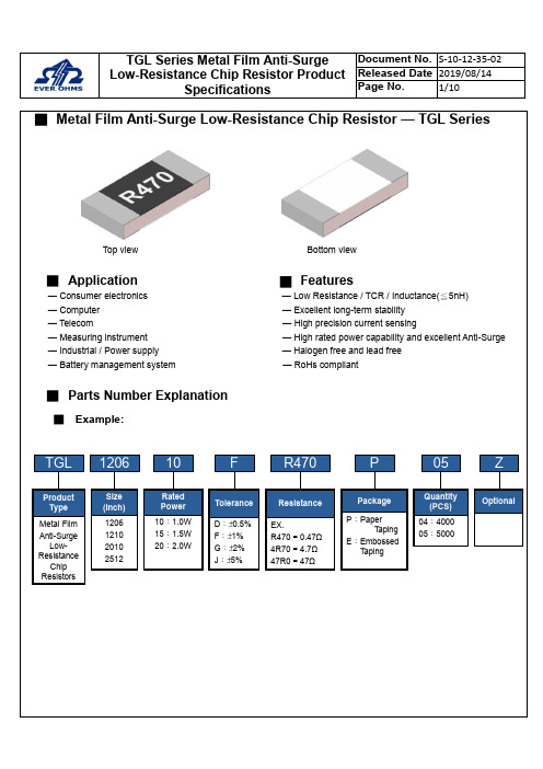
■Metal Film Anti-Surge Low-Resistance Chip Resistor — TGL SeriesTop view Bottom view■Application█Features— Consumer electronics — Low Resistance / TCR / Inductance(≦5nH)— Computer — Excellent long-term stability— Telecom — High precision current sensing— Measuring instrument — High rated power capability and excellent Anti-Surge — Industrial / Power supply — Halogen free and lead free— Battery management system — RoHs compliant■Parts Number Explanation■Example:Final Milestone DateCheckpointTGL1206F R470P05Size (Inch) 1206 1210 2010 2512ToleranceD:±0.5%F:±1%G:±2%J:±5%PackageP:PaperT apingE:EmbossedT apingQuantity(PCS)04:400005:5000ZOptionalProductTypeMetal Film Anti-SurgeLow-ResistanceChip ResistorsResistanceEX.R470=0.47Ω4R70=4.7Ω47R0=47Ω10RatedPower10:1.0W15:1.5W20:2.0W■Standard Electrical SpecificationsType RatedPowerat 70℃Max.RatedCurrentMax.OverloadCurrentT.C.R.(ppm/℃)Resistance RangeD(0.5%), F(1.0%), G(2.0%), J(5.0%)TGL1206 1W 3.16A 7.07A±50 100 mΩ ≦R ≦50 ΩTGL1210 1W 3.16A 7.07ATGL2010 1.5W 3.87A 8.66A±50 100 mΩ ≦R ≦50 ΩTGL2512 2W 4.47A 10.00A● For non-standard parts, please contact our sales dept.● Operating Temperature Range :−55℃〜+155℃.■Anti-Surge Ability:■Type Dimension■Construction Unit:mmTYPE L W H I1I2 TGL1206 3.10±0.10 1.60±0.10 0.55±0.10 0.40±0.20 0.45±0.20 TGL1210 3.10±0.10 2.50±0.15 0.55±0.10 0.50±0.20 0.50±0.20 TGL2010 5.00±0.20 2.50±0.15 0.55±0.10 0.60±0.25 0.60±0.25 TGL2512 6.30±0.20 3.20±0.20 0.55±0.10 0.65±0.25 0.65±0.25①Alumina Substrate ⑥Top Protective Overcoat②Resistive Layer ⑦Marking③Bottom Inner Electrode (Cu) ⑧Side Inner Electrode④Top Inner Electrode ⑨Barrier Layer (Ni)⑤Bottom Protective OvercoatWhite⑩Solder coating (Sn)■ Perfo r mance CharacteristicsPower Derating Curve ■The Operating Temperature Range: -55°C ~+155°C.Power rating or current rating is in the case based on continuous full-load at ambient temperature of 70℃. For operation at ambient temperature in excess of 70℃, the load should be derated in accordance with figure of derating Curve.■ Rated CurrentResistance Range: ≦ 1ΩRated Current: The resistor shall have a DC continuous working current or a AC (rms) continuous working current at commercial-line frequency and wave form corresponding to the power rating, as determined formula as following:I = Rated current (A) P= Rated Power (W) R= Resistance(Ω)■ Rated VoltageResistance Range: > 1ΩRated Voltage: The resistor shall have a DC continuous working voltage or a RMS AC continuous working voltage at commercial-line frequency and wave form corresponding to the power rating, as determined formula as following:V = Rated voltage (V)V = √P ×R P = Rated power (W)R = Nominal resistance (Ω)-5520406080100020406080100120140155℃Ambient Temperature (℃)Power Ratio(%)DERATING CURVE70160■Reliability Test and RequirementTest Item Test Method Procedure Requirements TemperatureCoefficient of Resistance(T.C.R) JIS C 5201-1clause 4.8TCR +125 ℃, 25 ℃is the reference temperatureRefer to StandardElectrical SpecificationsShort Time Overload JIS C 5201-1clause 4.135 times rated power for 5 seconds. ±(1.0%+0.001Ω)Insulation Resistance JIS C 5201-1clause 4.6100V for 1 minute. ≧10GΩDielectric Withstanding Voltage JIS-C5201-1clause 4.71206、1210、2010、2512 for 500 VAC 1minNo short or burned on theappearance.Core Body Strength JIS-C5201-1clause 4.15Central part pressurizing force:10N , 10 seconds No brokenSolderability JIS C 5201-1clause 4.17245±5°C for 3±0.5secs.>95% CoverageNo Visual damageResistance to Soldering Heat JIS-C5201-1clause 4.181. Molten solder, 260±5 °C,10±1 seconds immersion time2. IR reflow, refer to solder reflow temperature condition±(1.0%+0.001Ω)No Visual damageLeaching JIS-C5201-1clause 4.18260±5℃for 30 seconds.>95% CoverageNo Visual damageTemperature Cycling JIS C 5201-1clause 4.19-55℃to +155℃, 300 cycles±(1.0%+0.001Ω)No Visual damageLoad Life in Humidity JIS C 5201-1clause 4.2440±2℃, 90~95% R.H. , Rated power or Max. workingcurrent whichever is less for 1000 hrs with 1.5 hrs〝ON〞and 0.5 hr〝OFF〞.±(1.0%+0.001Ω)Load Life (Endurance) JIS C 5201-1clause 4.2570±2℃, Rated power, or Max. working current whichever isless for 1000 hrs with 1.5 hrs〝ON〞and 0.5 hr〝OFF〞.±(1.0%+0.001Ω)High Temperature Exposure JIS C 5201-1clause 4.25155±5℃for 1000 +48/-0 hours. ±(1.0%+0.001Ω)Resistance to Solvent JIS C 5201-1clause 4.29The tested resistor be immersed into isopropyl alcohol of20~25℃for 60 secs.Then the resistor is left in the room for 48 hrs.±(1.0%+0.001Ω)No Visual damageTerminal Strength JIS-C5201-1clause 4.32Pressurizing force for 10 seconds1206 and above:17.7NNo brokenTerminal Bending Strength JIS C 5201-1clause 4.33Bending once for 5 secondsD:1206、1210 = 3mm2010、2512 = 2mm±(1.0%+0.001Ω)No Visual damage● Temperature Coefficient of Resistance test to - 55 ℃is available on request■MarkingSolder reflow Temperature condition■Appendix For SMD Chip ResistorSIZE A ΦB ΦC■Packaging Information■Tapping SpecificationUnit: mm Packaging Type A B W E F G H T ΦD PPaper Type1206 1.90±0.2 3.05±0.28.0±0.2 1.75±0.1 3.5±0.05 4.0±0.1 2.0±0.050.75±0.1 4.0±0.11210 2.85±0.2 3.05±0.28.0±0.2 1.75±0.1 3.5±0.05 4.0±0.1 2.0±0.050.75±0.1 4.0±0.1■Embossed DimensionUnit: mm Packaging Type A B W E F G H T ΦDΦD1T1 PEmbossedType 2010 2.80±0.25.60±0.212±0.1 1.75±0.15.5±0.05 4.0±0.1 2.0±0.050.23±0.1 1.50±0.10.85±0.15 4.0±0.1 2512 3.40±0.2 6.70±0.212±0.1 1.75±0.15.5±0.05 4.0±0.1 2.0±0.050.23±0.1 1.50±0.10.85±0.15 4.0±0.1PaperCarrier■ Packing Material Data / Storage Data■ Front & Back Lead Dimension■ Top Adhesive Peel Off Strength :10~70g■ PackageInner Box Size Reel Size H(mm) 1 13 2 24 3 36 5 60 10113■ Storage Data :Storage time at the environment temp: 25±5℃& humidity: 60±20% is valid for one year from the date of delivery. External Box SizeContain (Kpcs) Length (mm)Width (mm)Width (mm)25K 180 180 60 50K 180 180 110 150K 430 200 200 300K400400200。
大毅2512合金低温漂采样电阻RLM25系列选型手册

pull 300 mm/min standard: 0.1 ~ 0.7 N
12. Storage Conditions:
Temperature: 5℃~35℃,Humidity:40%~75%
13. Shelf Life:
2 years from manufacturing date.
TA-I TECHNOLOGY CO., LTD
www.jepsun.com
Document No
TRLM-250S149C 2015/11/24 4/6
Lead-Free Current Sensing Resistors RLM Series ( Halogen-Free )
Issued date Page
7. Number of Package: 4000 Pieces / package
2. Type Designation:
RLM Item 25 Series No. 25:2512 (6432) F Resistance tolerance F:±1% G:±2% J:±5% E Packaging C Power rating C=1W D=1.5W E=2W R010 Resistance
Iron Solder:350±10℃ , 3+1/-0 sec
℃ , 5 sec
15. ECN
Engineering Change Notice: The customer will be informed with ECN if there is significant modification on the characteristics and materials described in Approval Sheet.
台湾大毅锰铜合金采样电阻RLF06系列选型手册
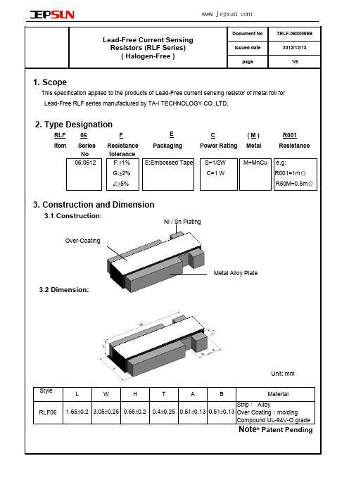
1. Scope
This specification applied to the products of Lead-Free current sensing resistor of metal foil for Lead-Free RLF series manufactured by TA-I TECHNOLOGY CO.,LTD.
www.jepsun.com
Document No TRLF-060S009B 2012/12/13 6/6
Lead-Free Current Sensing Resistors (RLF Series) ( Halogen-Free )
Issued date page
14. Recommend IR – Reflow profile : (solder: Sn96.5 / Ag3 / Cu0.5)
5. Reliability Tests
Test Items
Temperature Coefficient of Resistance Load Life Short Time Overload Moisture no Load Temperature cycle Resistance to Soldering Heat Solderability High Temperature Exposure Low Temperature Storage Substrate Bending Insulation Resistance
深圳捷比信--高品质精密元件供应商
www.jepsun.com
Document No TRLF-060S009B 2012/12/13 1/6
Lead-Free Current Sensing Resistors (RLF Series) ( Halogen-Free )
大毅AECQ汽车级合金采样电阻RLM25选型手册

Operation life Resistance to Soldering Heat Mechanic al Shock
Resistance to vibration
Condition of Test
Test Limits
+25 ~ 125℃
Refer 4.0
T=125℃,1000hrs,Measurement at 24hrs after test conclusion.
( Halogen-Free ) AEC-Q 200-Ver D qualified
10. Reel Specification
Document No TRLM-250S149E
Issued date
2019/03/14
Page
5/6
Series RLM 25
ψA
+0
180
-3
ψB 60 ±1.0
ψC 13.0±1.0
( Halogen-Free ) AEC-Q 200-Ver D qualified
Document No TRLM-250S149E
Issued date
2019/03/14
Page
4/6
7. Number of Package: 4000 Pieces / package
8. Label:
LOT NO:
Lead-Free Current Sensing Resi stors RLM Series
( Halogen-Free ) AEC-Q 200-Ver D qualified
Document No TRLM-250S149E
Issued date
Ralec合金电阻规格书
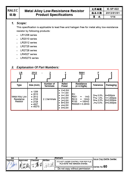
(0.645±0.254) (0.787±0.254)
LR2512
LR2725 LR2728
0.5 ~ 3.0
1.0 & 1.5
3.1 ~ 4.0 4.1 ~75.0
75.1 ~ 100.0
0.5 ~ 3.0
2.0
3.1 ~ 4.0
0.246±0.010 (6.248±0.254)
4.1 ~75.0
文件編號 版本日期 頁次
IE-SP-022 2013/01/01
3/14
3.1 Power Derating Curve: Operating Temperature Range: - 55 ~+170 ℃ For resistors operated in ambient temperatures 70°C, power rating shell be derated in accordance with the curve below:
Do not copy without permission
Issue Dep.DATA Center.
Series No.60
RALEC
旺詮
Metal Alloy Low-Resistance Resistor Product Specifications
文件編號 版本日期 頁次
IE-SP-022 2013/01/01
5/14
Type LR4527S (without heat sink)
LR4527
Maximum
Power Resistance
Rating Range (mΩ)
L
(Watts)
Dimensions - in inches (millimeters)
大毅1206毫欧低阻采样电阻RL12(20-91)系列选型手册
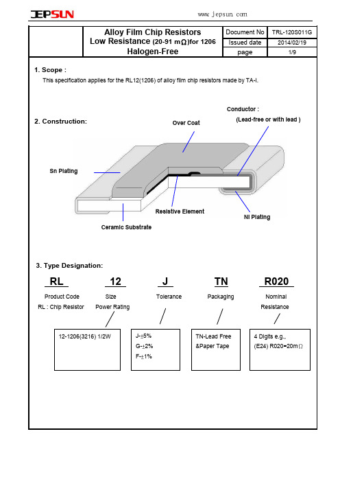
深圳捷比信--高品质精密元件供应商
www.jepsun.com
9. Label 9.1 Manufacture Label : Date Code QTY: 5000 PCS Lot No: T336B0026K C6 1336
page
Resistance Tolerance Type
R020
RL12JT
J
Manufacture Label
9.2 Customer Label( By customer request ): Lead-Free Products
TA-I TECH
Product Spec. Customer No:
1206 5%(T) 0.02Ω 105A702723 RL12JTNR020
LEAD FREE
04.05.21
Date
Year Month 10. Recommended land patterns
Land pattern Type Size
Solderability
IEC60115-1-4.17 JIS-C5201-1-4.17
245±5℃ solder, 2±0.5 sec dwell. Solder : Sn96.5 / Ag3.0 / Cu0.5
Robustness of Termination (Bending Strength)
Sn Plating
Resistive Element Ceramic Substrate
大毅厚膜高功率电阻RMH04-12系列选型手册

Thick Film High Power Chip Resistors (RMH series standard Halogen-Free) 6. Reliability Tests:
Test Items
Temperature Coefficient of Resistance
TRMH-XX0S001D
TRMH-XX0S001D
2012/09/28 3/11
For resistors operated at ambient temperature over 70℃ , power rating shall be derated in accordance with figure 1.
P Max
Power ratio(%)
Rapid Change of Temperature Solderability
IEC60115-1-4.19 JIS-C5201-1-4.19
-55℃ (30 min. ) / +155 ℃(30 min. ) 5 cycles
1%:±(0.5%+0.05Ω) 5%:±7 JIS-C5201-1-4.17
深圳捷比信--高品质精密元件供应商
www.jepsun.com
Document No. Revise Date page number
Thick Film High Power Chip Resistors (RMH series standard Halogen-Free)
5.1 Derating Curve :
Ambient Temp.(℃) Figure 1 5.2 Rated Voltage:
The rated voltage is calculated by the following formula:
旺诠电阻规格书
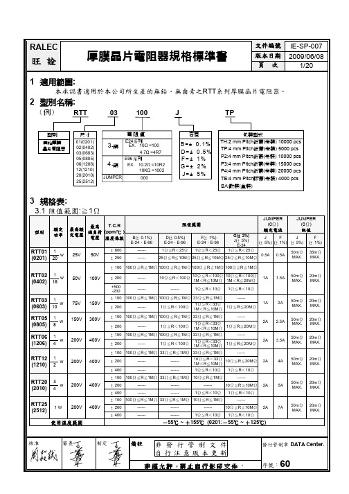
± 1000
19 ≦R<25 mΩ
± 700
25 ≦R<50 mΩ
± 400
50 ≦R<100 mΩ
± 200
100 ≦R<1000 mΩ
± 1500
10 ≦R<19 mΩ
± 1200
19 ≦R<25 mΩ
± 900
25 ≦R<50 mΩ
± 500
50 ≦R<100 mΩ
± 200
100 ≦R<1000 mΩ
6
2nd 保護層
2nd Protective coating
2 背面內部電極 Bottom inner electrode 7
字碼
Marking
3 正面內部電極 Top inner electrode 8 側面內部電極 Terminal inner electrode
4
電阻層
Resistive layer
序號:60
RALEC
旺詮
4 尺寸:
5 結構圖:
厚膜晶片電阻器規格標準書
文件編號 版本日期 頁次
IE-SP-007 2009/06/08
4/20
Unit : mm
Dimensions
L
W
TYPE Size Code
H
L1 L2
RTT01
0201 0.60± 0.03 0.30± 0.03 0.23± 0.03 0.15± 0.05 0.15AX.
核准
審查
制定
備註 非 發 行 管 制 文 件
自行注意版本更新
發行管制章 DATA Center.
非 經 允 許 ,禁 止 自 行 影 印 文 件 。
序號:60
RALEC
大毅1206、2010耐高压电阻RH12-20系列选型手册
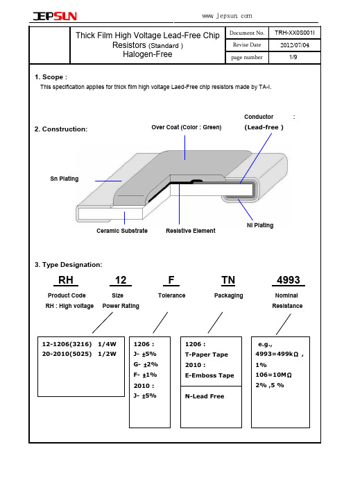
Rating voltage
Feature RH12 1/4W RH20 1/2W
Measurement Method JIS Code 3A / JIS Code 3D Refer to JIS C 5201-1-4.5 Refer to JIS C 5201-1-4.8
47Ω ~ 22MΩ
Checked by visual examination .
Temperature Coefficient of Resistance
IEC60115-1-4.8 JIS-C5201-1-4.8
-55 ~ +125 ℃
Refer to paragraph 5
Dielectric Withstanding Voltage ( Voltage Proof )
7.2 ±1% (E96 )
Resistance value is expressed by 4digits, the first three digits represent the significant figures of nominal resistance value inΩ, and the fourth digit represents exponent for base of 10. Ex. 4993 =499×10 =499000Ω=499kΩ
深圳捷比信--高品质精密元件供应商
www.jepsun.com
Document No. Revise Date page number TRH-XX0S001I 2012/07/04 3/9
Thick Film High Voltage Lead-Free Chip Resistors (Standard ) Halogen-Free
精密电阻电容电感选型手册

精密电阻电容电感选型手册,Resistor 电阻Automotive GradeNew Resistance TCR Product Type Series SPEC Tolerance Size Product Range (ppm/?)Automotive Grade ThinFilm Precision Chip 0402/0603/0805Resistor AR..A 10Ω~1MΩ ?0.05%~?1% 25/50 1206/1210 汽车等级高精密薄膜芯片2010/2512电阻Automotive Grade Chip 0402/0603/0805/1206 Resistor CR..A1Ω~100MΩ ?0.1%~?5%, 100/200/400 1210/2010/2512 汽车等级厚膜芯片电阻Automotive GradeAnti-Sulfurated Chip 0402/0603/0805/1206 AS..A1Ω~10MΩ ?0.5%,?1%,?5% 100/200 Resistor 1210/2010/2512汽车等级抗硫化芯片电阻Automotive Grade Current 0402/0603/0805Sensing Chip Resistor 100/150/200 1206/1210/2010 CS..A3mΩ~8000mΩ ?1%,?2%,?5% 汽车等级电流感应芯片电300/400/6002512/1225/3720阻 7520 Thin filmNew Resistance TCR Product Type Series SPEC Tolerance Size Product Range (ppm/?)0201/0402/0603 Thin Film Precision Chip Resistor 5/10/15 AR1Ω~3MΩ ?0.01%~?1% 0805/1206/1210 高精密薄膜芯片电阻 25/50 2010/2512Anti-Corrosive Thin Film 0402/0603/0805 Precision Chip Resistor PR 10Ω~1.5MΩ ?0.1%~?0.5% 15/25/50 1206/2010/2512 抗蚀高精密薄膜芯片电阻Thin Film Current Sensing Chip 0402/0603/0805 Resistor TCS50mΩ~1000mΩ ?0.5%,?1% 50/100/200 1206/2010/2512 电流感应芯片电阻Wire Bondable Chip Resistor WB 10Ω~332KΩ ?0.1%~?10% 25/50/100 0201/0402/0603 打线式芯片电阻Thin Film Anti-Sulfurated Chip TAS 24.9Ω~499KΩ ?0.05%~?1%10/15/25/50 0603/0805 Resistor曹小姐提供 010 - 5 6 0 3 4 1 9 5 viking台湾光颉提供高精密薄膜抗硫化芯片电阻Thin Film Array Chip Resistor TFAN 100Ω~33KΩ ?0.1%~?1% 10/15/25/50 0603x4 高精密薄膜芯片排阻Resistor ArrayNew TCR Product Type Series SPEC Resistance Range Tolerance Size Product (ppm/?)Thin Film Array Chip Resistor ?0.1%,?0.25% TFAN 100Ω~33KΩ10/15/25/50 0603x4 高精密薄膜芯片排阻 ?0.5%Thick Film Array Chip Resistor CN 1Ω~1MΩ ?1%,?5% 200 0402x4 厚膜芯片排阻 CNAThick Film Flat Array Chip Resistor CN-21 0201x2 10Ω~1MΩ ?5% 200 厚膜芯片平板排阻 CN-41 0201x4MELF/CarbonNew TCR Product Type Series SPEC Resistance Range Tolerance Size Product (ppm/?)Metal Film Precision Resistor 10/15/25 CSR 0.1Ω~10MΩ ?0.1%~?5% 0102/0204/0207tr> 金属精密薄膜电阻 50/100Metal Film Precision Resistor 10/15/25 CSRV 0.1Ω~1MΩ ?0.1%~?5% 0204/0207 金属精密薄膜电阻 50/100Carbon Film Resistor CFS 1Ω~1MΩ ?2%,?5% - 0204/0207/0309 碳膜无脚电阻Thick filmNew Resistance TCR Product Type Series SPEC Tolerance Size Product Range (ppm/?)01005/0201/0402 Thick Film Chip Resistor CR 1Ω~100MΩ ?0.1%~?5%50/100/200/400 /0603/0805/1206/ 厚膜芯片电阻 1210/2010/2512High Ohmic Chip Resistor HMR 110MΩ~1GΩ ?5% 500/1000 0805/1206 高阻值厚膜芯片电阻曹小姐提供 010 - 5 6 0 3 4 1 9 5 viking台湾光颉提供Pulse Withstanding Chip 0603/0805/1206 Resistor PWR1Ω~20MΩ ?0.5%~?5% 100/200 1210/2010/2512 耐突波贴片电阻Surge Withstanding Chip 0603/0805/1206 Resistor SWR1Ω~20MΩ ?5%~?20% 100/200 1210/2010/2512 抗浪涌芯片电阻High Voltage Thick Film 0402/0603/0805 Chip Resistor HVR10Ω~100MΩ ?1%,?5% 100/200/400 1206/2010/2512 耐高压厚膜芯片电阻Anti-Sulfurated Thick Film 0201/0402/0603Chip Resistor AS 1Ω~10MΩ ?0.5%,?1%,?5% 100/200 0805/1206/1210 抗硫化芯片电阻 2010/2512Trimmable Thick Film 0402/0603/0805Chip Resistor RT 1Ω~10MΩ -10%~-30% 100/200 1206/1210/2010 可雷切芯片电阻 2512 LeadedNew Resistance TCR Product Type Series SPEC Tolerance Size Product Range (ppm/?)Metal Film Leaded Precision 5/10/15/25 0318/0623/0932 Resistor MFR 0.1Ω~10MΩ ?0.05%~?1% 50/100 1145/1550 插件式金属精密电阻Me tal Film Leaded Resistor ?0.02%,?0.05%, MFD 10Ω~1MΩ 5/10/15/25 0727/1040 高精密金属膜固定电阻器 ?0.1%Carbon Film Leaded Resistor 0318/0623/0932 CFR 0.1Ω~22MΩ ?2%,?5% - 插件式碳膜电阻 1145/1550Metal Oxide Leaded Film 0623/0932/1145 Resistor MOF0.1Ω~22MΩ ?1%,?2%,?5% 200 1550/1765/2485 插件式金属氧化皮膜电阻Current sensingNew Resistance TCR Product Type Series SPEC Tolerance Size Product Range (ppm/?)0201/0402/0603 Current Sensing Chip 100/150/200/300 0805/1206/1210 Resistor CS 3mΩ~8000mΩ ?1%,?2%,?5% 400/600/1000 2010/2512/1225 电流感应芯片电阻 3720/7520 曹小姐提供 010 - 5 6 0 3 4 1 9 5 viking台湾光颉提供Thin Film Current 0402/0603/0805 Sensing Chip Resistor TCS50mΩ~1000mΩ ?0.5%,?1% 50/100/200 1206/2010/2512 薄膜电流感应芯片电阻Current Sensing Thick 0402/0603/0805 200/500/800 Film Chip Resistor RS 10mΩ~976mΩ ?1%, ?5% 1206/1210/2010 1200/1500 电流感应芯片电阻 2512Ultra Low Ohm (MetalStrip) Chip Resistor LR 0.5mΩ~15mΩ ?1%,?3%,?5% 50/75/100/1501206/2010/2512 1W~3W合金超低阻芯片电阻Chip Shunt Resistor 50/60/75 LRS 0.5mΩ~4mΩ ?1%,?2%,?5% 1050/1575分流芯片电阻 100/120Current Sensing Metal 0805/1206 Chip Resistor CSM10mΩ~100mΩ ?1%,?2%,?5% 50/100 2010/2512 电流感应金属芯片电阻Low Ohm (Metal Strip)Chip Resistor LRM 5mΩ~100mΩ ?1%,?2%,?5% 75/100 1206/2010/2512 合金低阻芯片电阻Power resistorPower ResistorNew TCR Product Type Series SPEC Resistance Range Tolerance power Product (ppm/?)TO-220 Power Resistor ?0.5%,1%, 5%, TR20 0.05Ω~10KΩ 50/100/200/300 20W 插件式功率电阻 10%TO-220 Power Resistor ?0.5%,1%, 5%, TR30 0.05Ω~10KΩ 50/100/200/300 30W 插件式功率电阻 10%TO-220 Power Resistor ?0.5%,1%, 5%, TR35 0.05Ω~10KΩ 50/100/200/300 35W 插件式功率电阻 10%TO-220 Power Resistor ?0.5%,1%, 5%, TR50 0.1Ω~10KΩ 50/100/200/300 50W 插件式功率电阻 10%TO-247 Power Resistor ?0.5%,1%, 5%, TR100 0.05Ω~10KΩ50/100/200/300 100W 插件式功率电阻 10%曹小姐提供 010 - 5 6 0 3 4 1 9 5 viking台湾光颉提供TO-220 Power Resistor ?0.5%,1%, 5%, TR50-H 0.1Ω~10KΩ50/100/200/300 50W 插件式功率电阻 10%,Inductor 电感高频电感(RF Inductor)New Inductance Product Product Description Series SPEC Curve Tolerance SRF(MHZ) DCR(Ω) IDC(mA) Size Product RangeThin Film Chip 0201 Inductor ?0.1,0.2,0.3nH AL 0.1nH~100nH1000~14000 0.1~7.5 75~800 0402 高频薄膜精密芯片电?1%,2%,3%,5% 0603 感Multilayer Chip ?0.3nH 0402 Inductor CL 1nH~220nH 600~10000 0.1~2.7 100~500 ?5%,10% 0603 高频陶瓷积层电感Wire Wound Chip 0402Inductor 0603(Low Profile, High Q, WL 1nH~15000nH ?2%, 5%,10% 15~12700 0.02~11.5 80~2400 0805 Current, High SRF) 1008高频陶瓷绕线电感 1206功率电感(Power Inductor)New Product Inductance Product Series SPEC Tolerance DCR(Ω) I DC(A) Size Product Description RangeNon-shielded,High Power, WireWound Power ?20% 1608/1813/3316 PDH 0.47u~100uH 0.003~1.6 0.4~30 Inductor +40%-20% 4920/5022 开磁路绕线功率电感Non-shielded,Wire Wound Power 1608/3308/3316 Inductor PD 0.18u~1000uH ?20%,30% 0.007~13.8 0.1~40 3340/5022 开磁路绕线功率电感曹小姐提供 010 - 5 6 0 3 4 1 9 5 viking台湾光颉提供Non-shielded,Low Profile Wire 0301/0302/0402/0403 Wound Power PCD1.0u~1000uH ?10%,20% 0.01~10.19 0.09~9.5 0502/0503/0504/0703 Inductor 0705/1004/1005/1006 开磁路绕线功率电感Low Profile , Mini Wire Wound Power Inductor MPI 1.2u~1000uH ?20%, 0.04~22.6 0.08~2.5 0610/0612/0620 小型绕线功率电感Low Profile , Mini Wire Wound Power Inductor MPE 1u~68uH ?20%,30% 0.08~4.2 0.17~1.4 0312 小型绕线功率电感Shielded, Wire Wound Power Inductor PS 1u-10000uH ?10%,20%0.021~32.8 0.02~5 1608/3316/5022 闭磁路绕线功率电感Shielded, Wire Wound Power ?20% 62B/64B/73/74 Inductor PCS 1.2u-1000uH 0.007~9.44 0.14~9.8 +40%-20% 124/125/127 闭磁路绕线功率电感Shielded, Wire Wound Power 0628/0728/0730Inductor PCDR 1.2u~1500uH ?20%,30% 0.0069~4.78 0.13~130732/0745/1045 闭磁路绕线功率1255/1265/1275电感Shielded, Low Cost, Wire Wound Power Inductor PCDS10u~820uH ?20%,30% 0.03~2 0.33~3.15 63B/74B/105B/125B 闭磁路绕线功率电感Shielded, Low Profile Wire Wound Power 5D28 PSDB 1.3u~1000uH ?30% 0.006~1.989 0.4~10.5 Inductor 1003/1004/1005 闭磁路绕线功率电感曹小姐提供 010 - 5 6 0 3 4 1 9 5 viking台湾光颉提供Shielded, Low Profile Wire Wound Power 2D12/2D15 SCDB1.2u~47uH ?20%,30% 1.2~47 0.22~1.1 Inductor 2D18 闭磁路绕线功率电感Shielded, Low Profile Wire 3D18Wound Power 4D18/4D22/4D28 SCDS 1u~470uH ?30% 0.012~6.56 0.13~6.15 Inductor 5D18/5D28 闭磁路绕线功率6D28/6D38电感Shielded Wire 4010/4020/4030 Wound Power 5010/ 5020/5030 Inductor PCF 0.36u~10000uH ?20%,30% 0.005~201.16 0.026~12.6 6915/6919/7040 闭磁路绕线功率1015/1040/1062 电感Shielded, Low Profile Wire Wound Power 0.47u~ 0302/0303/0418PDRH ?20%,30% 0.009~175.4 17~4820 Inductor 27000uH 0501/0502/0503 闭磁路绕线功率电感Shielded, Wire Wound Power Inductor SDRH 1.0u~100uH ?30% 0.0095~0.43 0.75~9 0830/0840/0845 闭磁路绕线功率电感Shielded, Wire Wound Power Inductor SDB 0.10u~47uH ?20% 0.0015~0.210 1.2~32.5 0630/1040 闭磁路绕线功率电感Miniature Wire Wound Power 0312/0412/0612 Inductor SDIA1u~100uH ?20% 0.016~60 0.05~8.16 0820/0825/0840 小型绕线功率电感Shielded, 201609E/201514 Non-shielded, ?5%,10% 321618C/322515 Miniature Wire VLH 0.1u~10000uH 0.0098~140 0.023~50 ?20%,30%322520C/453226C Wound Power 575047C Inductor曹小姐提供 010 - 5 6 0 3 4 1 9 5 viking台湾光颉提供小型绕线功率电感Shielded, LowProfile Wire 2D10/2D15/2D18 SCDA 0.47uH~100uH ?20%,?30% 0.035~3.840.18~3.9 Wound Power 3D12/3D15/3D18 Inductor磁芯电感(Ferrite Inductor)New Product Inductance Product Series SPEC Tolerance SRF(MHZ) DCR(Ω) IDC(mA) Size Product Description RangeMultilayerFerrite ChipInductor ML 0.01~33uH ?10%,20% 13~320 0.15~2.55 5~300 0603/0805/1206 积层芯片式黑电感Multilayer 0402/0603/0805/1204 Chip Bead CB 5~2700Ω ?25% - 0.01~250~6000 1206/1210/1808/1812 贴片磁珠Wound ChipInductors(Ferrite) ?5%,10% 0805/1008/1210 NL 0.12uH~1000uH 0.5~800 0.03~150 30~1800 铁芯绕线电感?20% 1812/2220 (开放,铸膜及背胶)Chip CommonMode Choke CM 67~2200Ω ?20% - 0.25~1.2 200~400 0805/1206 共模滤波器插件式电感(DIP Power Inductor)New Product Inductance Product Series SPEC Tolerance DCR(Ω) IDC(A) Size Product Description RangeDIP PowerInductor DRGH 10u~47000uH ?10%,20% 0.022~96.4 0.038~5.3664/855/875/895/106/108/110 插件式开磁路功率电感曹小姐提供 010 - 5 6 0 3 4 1 9 5 viking台湾光颉提供DIP PowerInductor DRGR 10u~10000uH ?10%,20% 0.023~35 0.074~3.51664/875/108/110 插件式闭磁路功率电感DIP Power 0708/0808/1210 DM 0.22u~33uH ?20% 0.0006~0.025 6~56 Inductor 1310/1818,Capacitor 电容积层电容(SMD Capacitor)New Product Capacitance Picture Series SPEC Tolerance Voltage Material Size Product Description Range Multilayer ?0.1,0.25,0.5pF Ceramic 6.3V,10V,16V NPO/X7R 0402/0603/0805 MC-1 0.5pF~100uF ?5%,10%,20% Capacitor 25V,50V,100V X5R/Y5V 1206/1210/1812 -20/+80% 迭层贴片电容MultilayerCeramicCapacitor ?0.25,0.5pF (Middle & 200V,250V,500V NPO/X7R0603/0805/1206 MC-2 0.5pF~0.68uF ?5%,10%,20% High 630V,1KV,2KV,3KV Y5V 1210/1808/1812 -20/+80% Voltage)中高壓迭层贴片电容MultilayerCeramicCapacitor ?0.25,0.5pF 6.3V,10V,16V NPO/X7R (Ultra-Small MC-30.3pF~0.1uF 0201 ?5%,10%,20% 25V,50V X5R Capacitor)小型迭层贴片电容MultilayerCeramicCapacitor ?0.1,0.25,0.5pF MCHL 0.5pF~3300pF 16V,25V,50V,100V NPO0402/0603/0805 (High Q, Low ?5%ESR)迭层贴片电容Multilayer ?0.05,0.1,0.25,0.5pF 6.3V,10V,25V 0201/0402/0603 Ceramic MCRF 0.1pF~100pF NPO ?1%,2%,5% 50V,100V,250V 0805 Capacitor曹小姐提供 010 - 5 6 0 3 4 1 9 5 viking台湾光颉提供(Ultra HighQ, Low ESR)高频迭层贴片电容MultilayerCeramicCapacitor(Low MCLI 10nF~150nF ?10%,20% 50V X7R 0612 Inductance)低感迭层贴片电容------------------------------ 咨询及样品申请,请联系光颉viking代理: 曹小姐提供**************************曹小姐提供 010 - 5 6 0 3 4 1 9 5 viking台湾光颉提供。
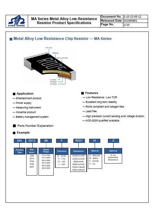
台湾天二汽车级合金采样电阻MA系列选型手册
■ Marking Format:
● All the other products marking are 4 digits. ● “R” designates the decimal location in ohms
6.800±0.254 6.600±0.254
1.650±0.254 3.050±0.20±0.254 0.630±0.254 0.430±0.254 0.650±0.254
0.510±0.254
0.410±0.254 0.650±0.254
— ACE-Q200 qualified available.
R001
M
Z
Product Type
Size (Inch)
1206 2512 2725 2728 4527
Rated Power
07=0.75W 10=1.00W 20=2.00W 30=3.00W 40=4.00W 50=5.00W
Tolerance
e.g. 1mΩ the product marking is R001. 25mΩ the product marking is R025. 100mΩ the product marking is R100.
● “m” designates the decimal location in milli-ohms e.g. 0.25mΩ the product marking is 0m25. 0.5mΩ the product marking is 0m50. 5.5mΩ the product marking is 5m50. 25.5mΩ the product marking is 25m5.
台湾华新科SF-H系列高精度厚膜电阻选型手册
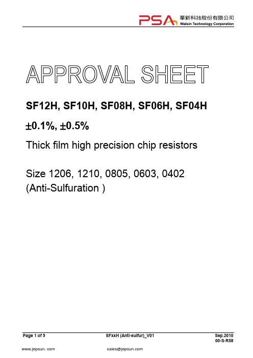
SF12H, SF10H, SF08H, SF06H, SF04H ±0.1%, ±0.5%Thick film high precision chip resistorsSize 1206, 1210, 0805, 0603, 0402 (Anti-Sulfuration )FEATURE1. High reliability and stability±1%2. Sulfuration resistant 1000ppm3. Automotive grade AEC Q-200 Compliant4. 100% CCD inspection5. RoHS compliant and Lead free productsAPPLICATION∙Automotive application∙Consumer electrical equipment∙EDP, Computer application∙Telecom applicationDESCRIPTIONThe resistors are constructed in a high grade ceramic body (aluminum oxide). Internal metal electrodes are added at each end and connected by a resistive paste that is applied to the top surface of the substrate. The extra protective metal film is added onto top side electrodes to protect termination from sulfuration. The composition of the paste is adjusted to give the approximate resistance required and the value is trimmed to within tolerance by laser cutting of this resistive layer.The resistive layer is covered with a protective coat. Finally, the two external end terminations are added. For ease of soldering the outer layer of these end terminations is a Tin (lead free) alloy.Fig 1. Construction of a Chip-RQUICK REFERENCE DATANote : 1. This is the maximum voltage that may be continuously supplied to the resistor e lement,see “IEC publication 60115-8”2.Max. Operation Voltage : So called RCWV (Rated Continuous Working Voltage) is determined byValue Res is tance Power Rated RCWV ⨯=or Max. RCWV listed above, whichever is lower.DIMENSIONS (unit : mm)MARKING3-digits marking(0603)4-digits marking(1210/1206/0805)Each resistor is marked with a four digits code on the protective coating to designate the nominal resistance value. ExampleFUNCTIONAL DESCRIPTIONProduct characterizationStandard values of nominal resistance are taken from the E24& E96 series for resistors with a tolerance of ±0.5%, ±0.1%. The values of the E24/E96 series are in accordance with “IEC publication 60063”DeratingThe power that the resistor can dissipate depends on the operating temperature; see Fig.2Figure 2 Maximum dissipation in percentage of rated power as afunction of the ambient temperatureMOUNTINGDue to their rectangular shapes and small tolerances, Surface Mountable Resistors are suitable for handling by automatic placement systems.Chip placement can be on ceramic substrates and printed-circuit boards (PCBs).Electrical connection to the circuit is by individual soldering condition.The end terminations guarantee a reliable contact.SOLDERING CONDITION Array The robust construction of chip resistors allowsthem to be completely immersed in a solder bathof 260︒C for 10 seconds. Therefore, it is possibleto mount Surface Mount Resistors on one side ofa PCB and other discrete components on thereverse (mixed PCBs).Surface Mount Resistors are tested forsolderability at 235︒C during 2 seconds. The testcondition for no leaching is 260︒C for 30 seconds.Typical examples of soldering processes thatprovide reliable joints without any damage aregiven in Fig 3.Fig 3. Infrared soldering profile for Chip Resistors CATALOGUE NUMBERSThe resistors have a catalogue number starting with .* Anti-Sulfur test conditions: H2S 1000ppm, 25’C, RH 90%, 720hrs, acceptance criteria: +/-1.0%.SF10, SF12, SF08, SF06:1. Reeled tape packaging : 8mm width paper taping 5000pcs per 7” reel, 10kpcs per 10” reel, 20kpcs per 13” reel.2. Bulk packaging : 5000pcs per poly-bagSF04:1. Reeled tape packaging : 8mm width paper taping 10,000pcs per reel,2. Bulk packaging : 10,000pcs per poly-bagTEST AND REQUIREMENTSEssentially all tests are carried out according to the schedule of IEC publication 115-8, category LCT/UCT/56(rated temperature range : L ower C ategory T emperature, U pper C ategory T emperature; damp heat, long term, 56 days). The testing also meets the requirements specified by EIA, EIAJ and JIS.The tests are carried out in accordance with IEC publication 68, "Recommended basic climatic and mechanical robustness testing procedure for electronic components" and under standard atmospheric conditions according to IEC 60068-1, sub-clause 5.3. Unless otherwise specified, the following value supplied :Temperature: 15°C to 35°C.Relative humidity: 45% to 75%.Air pressure: 86kPa to 106 kPa (860 mbar to 1060 mbar).All soldering tests are performed with midly activated flux.PACKAGING(unit :mm)Paper Tape specifications7” Reel dimensions。
大毅0.5mR合金采样电阻RLM25_R50m系列选型规格书

RLM series manufactured by TA-I TECHNOLOGY CO.,LTD.
深圳捷比信--高品质精密元件供应商
www.jepsun.com
Lead-Free Current Sensing Resistors
RLM Series
( Halogen-Free )
Document No
TRLM-25OS153A
Issued date
2012/12/1esistance
e.g :
R50m=0.5mΩ
3. Construction and Dimension :
3.1 Construction:
Over-Coat
Ni / Sn
Plating
Metal Alloy Plate
3.2 Dimension:
R50m
UNIT : mm
Style
RLM25
±200ppm/℃
±1%、±2%、±5%
Over 100MΩ
(P*R)1/2
Operation Temperature Range
Temperature Coefficient of Resistance
Tolerance
Insulation Resistance
Maximum Working Voltage(V)
V:Rated Voltage(V)
V= ×
P:Rated Power(W)
1206 50r贴片电阻
1206 50r贴片电阻什么是1206 50r贴片电阻?1206 50r贴片电阻是一种被广泛使用的电子元件,是电子设备中常见的电阻器。
其中,“1206”代表了该电阻的尺寸,50r代表了其电阻值。
在电子领域中,贴片电阻的尺寸通常由其长度和宽度来表示,以毫米为单位。
1206贴片电阻的尺寸为1.2毫米长和0.6毫米宽。
为什么要使用1206 50r贴片电阻?贴片电阻主要用于调整和限制电流的流动,以及改变电路中的电压。
它们在电子设备中的应用非常广泛,因为它们具有小尺寸、容易安装和耐用等优点。
1206 50r贴片电阻是尺寸较大的一种贴片电阻,因此在电路中较为容易识别和操作。
如何使用1206 50r贴片电阻?使用1206 50r贴片电阻的第一步是确认其正确的引脚连接。
通常,它们具有两个金属引脚,其中一个是电阻的输入端,另一个是输出端。
将电阻与正确的引脚连接,以确保其可以正确工作。
接下来,根据所需的电阻值,在电路中正确选择并连接1206 50r贴片电阻。
贴片电阻的电阻值标识通常以欧姆(ohms)为单位,并在电阻身上使用彩色或数字编码进行标记。
在这种情况下,50r代表电阻值为50欧姆。
将电阻与电路中的其他元件正确连接,以实现所需的电流或电压控制。
这通常涉及将电阻插入电路中的正确位置,并使用焊接或其他连接方法进行固定。
最后,确保电路连接安全可靠,并进行必要的测试和检查。
使用仪器检测电阻的电阻值,并确认其是否符合制造商提供的规格。
总结:1206 50r贴片电阻是一种常用的电子元件,用于调整和限制电流流动以及改变电路中的电压。
使用它们的第一步是确认正确的引脚连接,然后根据所需的电阻值选择和连接电阻。
最后,确保电路连接安全可靠,并进行必要的测试和检查。
通过正确使用和处理1206 50r贴片电阻,可以确保电子设备的正常运行。
1206合金采样电阻 -回复
1206合金采样电阻-回复1206合金采样电阻是一种常见的电子元器件,它在电路设计和制造中起着重要的作用。
本文将从以下几个方面详细介绍1206合金采样电阻的相关知识。
一、什么是1206合金采样电阻?1206合金采样电阻是一种贴片电阻,也称为表面贴装电阻。
它采用1206封装尺寸,封装尺寸的命名方式是指器件的封装尺寸为0.12英寸长、0.06英寸宽。
1206合金采样电阻的使用广泛,可以应用于各种电子设备和电路中。
二、1206合金采样电阻的结构和特点是什么?1206合金采样电阻的结构相对简单,它主要由一条或多条金属电阻体组成,两端焊有金属引脚,以便能够与电路板上的焊盘连接。
1206合金采样电阻的特点包括以下几个方面:1. 封装小巧:1206封装尺寸的电阻相对较小,适合在空间有限的电子设备中应用。
2. 贴片结构:1206合金采样电阻采用贴片结构,使得它可以方便地焊接在电路板上,节省了安装的时间和人力成本。
3. 稳定性好:1206合金采样电阻的稳定性较高,能够提供精确的电阻值,并且能够在较宽的温度范围内保持稳定。
4. 工作电压范围广:1206合金采样电阻能够在较宽的电压范围内工作,适用于不同电路和设备的需求。
5. 耐高温性能好:1206合金采样电阻能够在一定的温度范围内工作,具有良好的耐高温性能,可以在高温环境下使用。
三、1206合金采样电阻的应用领域有哪些?由于1206合金采样电阻的特点和性能优势,它在各种电子设备和电路中都有广泛的应用。
以下是一些常见的应用领域:1. 通信设备:1206合金采样电阻可以用于手机、无线通信设备等电子产品中,起到电路保护和电阻匹配的作用。
2. 汽车电子:1206合金采样电阻可以应用于汽车电子中,如车载导航、空调控制等,帮助实现电子设备的正常工作。
3. 智能家居:1206合金采样电阻在智能家居产品中也有一定的应用,如智能插座、智能灯具等,帮助实现电路的精确控制。
4. 数字设备:1206合金采样电阻可以用于各类数字设备,如计算机、平板电脑等,辅助完成电路的功能。
大毅合金电阻
大毅合金电阻1. 简介大毅合金电阻是一种广泛应用于电子领域的电阻器件。
它采用合金材料制成,具有高温、高精度、耐腐蚀等优点。
在电子电路中,电阻器常用于控制电流、调节电压以及实现信号传输与分配等功能。
大毅合金电阻作为一种重要的电阻器件,在各个领域都有着广泛的应用。
2. 原理与优势大毅合金电阻的工作原理基于电阻材料的特性,通过材料的电导率、电阻率以及截面积等参数来控制电阻的大小。
合金材料具有较高的电阻率,因此可以制成较大阻值的电阻器。
同时,合金材料具有优良的温度稳定性,能够在高温环境下保持较好的电阻特性。
大毅合金电阻的优势主要体现在以下几个方面:2.1 高温性能大毅合金电阻采用高温电阻材料制成,能够在较高温度下正常工作。
这使得它在高温环境下的应用得到了广泛的推广,例如汽车发动机控制系统、焊接设备等。
2.2 高精度大毅合金电阻具有较高的精度,通常可以达到1%或更高的精度要求。
这使得它在精密电子仪器、测量设备以及自动控制系统等领域中得到了广泛应用。
2.3 耐腐蚀性大毅合金电阻采用耐腐蚀材料制成,能够在恶劣环境中稳定工作,并具有较长的使用寿命。
这使得大毅合金电阻在化学工业、海洋工程等领域中起到了重要的作用。
2.4 温度系数小大毅合金电阻的温度系数小,即在一定温度范围内,电阻值变化较小。
这使得它在温度变化较大的环境下,仍能保持较好的电阻特性,不会对电子电路的稳定性产生较大影响。
3. 应用领域大毅合金电阻广泛应用于各个领域,以下是几个主要的应用领域:3.1 汽车电子在汽车电子系统中,大毅合金电阻用于各种传感器电路、控制模块、点火系统等。
它能够在高温环境下保持稳定的电阻特性,确保车辆的稳定性和安全性。
3.2 工控自动化在工业自动化领域中,大毅合金电阻常用于控制系统、测量仪器以及精密设备等。
它的高精度和稳定性能,能够满足各个工业应用的要求。
3.3 通信设备在通信设备中,大毅合金电阻主要用于电子滤波器、耦合器、终端设备等。
- 1、下载文档前请自行甄别文档内容的完整性,平台不提供额外的编辑、内容补充、找答案等附加服务。
- 2、"仅部分预览"的文档,不可在线预览部分如存在完整性等问题,可反馈申请退款(可完整预览的文档不适用该条件!)。
- 3、如文档侵犯您的权益,请联系客服反馈,我们会尽快为您处理(人工客服工作时间:9:00-18:30)。
www.jepsun.com
Document No TRLM-120S030A 2012/12/13 1/6
Current Sensing Resistors RLM Series ( Halogen-Free )
Issued date page
1. Scope:
This specification applied to the products of current sensing resistor of metal foil for Lead-Free RLM series manufactured by TA-I TECHNOLOGY CO., LTD.
1.1 ± 0.30 (R=1mΩ)
t
0.75 ± 0.20 (R=1mΩ) 0.6 ± 0.20 (2mΩ≦R≦30mΩ)
Material
Strip: Alloy Over Coating : molding Compound UL-94 grade
RLM12 3.2±0.20 1.6±0.20
0.5 ± 0.30 (2mΩ≦R≦30mΩ)
深圳捷比信--高品质精密元件供应商
www.jepsun.com
Document No TRLM-120S030A 2012/12/13 6/6
Current Sensing Resistors RLM Series ( Halogen-Free )
Issued date page
14. Recommend IR – Reflow profile: (solder: Sn96.5 / Ag3 / Cu0.5)
L 1.0 1.6 Unit: mm
深圳捷比信--高品质精密元件供应商
www.jepsun.com
Document No TRLM-120S030A 2012/12/13 4/6
Current Sensing Resistors RLM Series ( Halogen-Free )
Issued date page
Power Ratio (%)
100
-55
70 Ambient Temperature (℃)
170
5.2 Rated Voltage
The rated voltage is calculated by the following formula:
V: Rated Voltage (V)
V PR
1000hours at rated power, 70℃, 1.5hours < ±1% “ON”, 0.5hour “OFF” 5 X rated power for 5s < ±1%
IEC60115-1 4.24.2.1a) 85℃, 85%RH, 1000hrs < ±0.5% JIS C 5201-1 4.24.2.1a) -55℃ & +155℃, IEC60115-1 4.19 < ±0.5% 300cycle, 15min per JIS C 5201-1 4.19 extreme condition IEC60115-1 4.18 260±5℃ for20±1 sec < ±0.5% JIS C 5201-1 4.18 At least 95% of surface area IEC60115-1 4.17 245±5℃, 2±0.5sec of electrode shall be JIS C 5201-1 4.17 covered with new solder IEC60115-1 4.23.2 170℃, 1000hrs < ±1% JIS C 5201-1 4.23.2 EC60115-1 4.23.4 -55℃, 1000hrs <±1% JIS C 5201-1 4.23.4 IEC60115-1 4.33 Bending width 2mm < ±0.5% JIS C 5201-1 4.33 IEC60115-1 4.6 100V DC for 1 minute >100 MΩ JIS C 5201-1 4.6
ψA 178±2.0
ψB 60.0±1.0
ψC 13.0±1.0
W 9.0±1.0
T 11.5±1.0
11. Peeling Strength of Top Cover Tape
Test Condition: 0.1 to 0.7 N at a peel-off speed of 300 mm / min.
2. Type Designation:
RLM Item 12 Series No 12:1206 (3216) F Resistance tolerance F:±1% G:±2% J:±5% T Packaging C Power Rating M Metal R001 Resistance
T: Paper Tape
Top cover tape 10 ~15∘ Carrier tape
Pull 300 mm/min standard: 0.1 ~ 0.7 N
12. Storage Conditions:
Temperature: 5℃~35℃,Humidity:40%~75%
13. Shelf Life:
2 years from manufacturing date.
深圳捷比信--高品质精密元件供应商
www.jepsun.com
Document No TRLM-120S030A 2012/12/13 3/6
Current Sensing Resistors RLM Series ( Halogen-Free )
Issued date page
5.1Derating Curve
6. Recommended Solder Pad Dimension
L
P: Rated Power (W) R: Resistance Value (Ω)
b
a
Cu Trace
Sensing Trace
Resistance Range (Ω ) 0.001 0.002~0.030
a 1.8 1.8
b 2.3 1.7
Customer Label
9. Taping
Packing
Type
A
B
3.6±0.2
W
8.0.±0.2
F
3.5±0.05
E
1.75±0.1
P1
4.0±0.1
P2
2.0±0.05
P0
4.0±0.1
D0
T
0.84±0.1
Paper Tape RLM12 2.0±0.15
ψ1.5 (+0.1/-0)
深圳捷比信--高品质精密元件供应商
深圳捷比信--高品质精密元件供应商
www.jepsun.com
Document No TRLM-120S030A 2012/12/13 2/6
Current Sensing Resistors RLM Series ( Halogen-Free )
Issued date page
4. Features: Type Power Rating Resistance Value Operation Temperature Range Temperature Coefficient of Resistance Tolerance Insulation Resistance Maximum Working Voltage(V) RLM12 1/4W & 1/2W & 1W 1~30mΩ -55℃~+170℃ ±200ppm/℃ R=1mΩ ±100ppm/℃ 2mΩ≦R≦10mΩ ±75ppm/℃ R>10mΩ ±1%、±2%、±5% Over 100MΩ (P*R)1/2
7. Number of Package: 5000 Pieces / package
8. Label:
Date Code
Series
Resistance
QTY: 5000 PCS
LOT NO:
R010 FTC
RLM12FTC
T019C0071H
1019
Tolerance
Package
Power Rating
5 ℃ , 5 sec 0 Pre–heat zone : 150 to 180 ℃, 90±30 sec Soldering zone : 230℃ or higher , 30±10 sec
Peak : 250
15. ECN
Engineering Change Notice: The customer will be informed with ECN if there is significant modification on the characteristics and materials described in approval sheet.
2
Note*:1 Watts with total solder pad and trace size of 300mm
5. Reliability Tests:
Test Items Temperature Coefficient of Resistance Load Life Short Time Overload Moisture no Load Temperature cycle Resistance to Soldering Heat Solderability High Temperature Exposure Low Temperature Storage Substrate Bending Insulation Resistance Reference standard IEC60115-1 4.8 JIS C 5201-1 4.8 IEC60115-1 4.25.1 JIS C 5201-1 4.25.1 IEC60115-1 4.13 JIS C 5201-1 4.13 Condition of Test +25℃ ~ +125℃ Test Limits Refer 4.0
