LE8200使用说明书
013 8100、8200控制屏说明

Logo
8120控制屏说明
主控制器为BE24控制器
科泰电源设备(上海)有限公司
COOLTECH POWER(SHANGHAI)LTD.
Logo
8120控制屏说明
主控制器参量信息
1、低燃油液位报警指示 2、紧急停机报警指示 3、低油压停机报警指示 4、高水温停机报警指示 5、电池电压值 6、皮带断裂/充电发电机故障报警指示 7、超/低频率停机报警指示 8、启动失败停机报警指示 9、交流发电机故障
科泰电源设备(上海)有限公司
COOLTECH POWER(SHANGHAI)LTD.
Logo
8100控制屏说明 8100控制屏(501K) 8100控制屏(501K)电路原理 控制屏
科泰电源设备(上海)有限公司
COOLTECH POWER(SHANGHAI)LTD.
Logo
8120控制屏说明
二、8120控制屏说明 8120控制屏说明
Logo
8100、8120、8200、8220控制屏说明 8100、8120、8200、8220控制屏说明
科泰电源设备(上海)有限公司
—销售服务中心
版本编号:VO.0801-13
Logo
8100、8200控制屏说明 8100、8200控制屏说明 目 录 1、8100控制屏说明 2、8120控制屏说明 3、8200控制屏说明 4、8220控制屏说明 5、KX系列ATS
科泰电源设备(上海)有限公司
COOLTECH POWER(SHANGHAI)LTD.
Logo
8120控制屏说明
控制屏外面板 1.主控制器:整个系统的主控制器; 2.微型空气开关:控制线路过流及短路保护; 3.紧急停机按钮
3
LENZE8200简明调试及典型接线
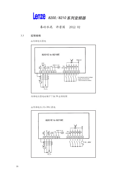
,(00 D11 D1/ D1&
f/02Lij8 # kl " f/0mn8 f/02Lio8 # kl " h g
,(10 )*#,
)*&+
r8& D11 $D1/$D1& /stp 100 u $ vwxyz{|P $ }~ 8 & E@FGH / %
!"
+)
+),)
,&’(),BCDEFGHIJ #KLMN,6OPQRSTUVWXYZ? $
! .-(( [\]^_‘ ! ! !
abc .-(( 0 .-,( 4$%defg]^ $ hijklm #.-(( n .-,( [\ ]^l’of Z?p’ qr_stu,6EF4$%./
vKL6wx # yz){|}~P $ }~P & e +1.(123 l 4$% $
!"
#$5(!
56 56
uM B vwxXyz{|}~v C MX{|} $ ]^
R "ST5UV0WXY #$0%D Z[ $ \]^ %_‘a[bcC ! V* #%$&E/%/
-./012 !3
,&, @A $4’&55 DE*+,
@ABCHI @A $4’&55 *+8=
,4, @ABC $ DE*+,
@ABCHI @A 67*89 *+8=
,3, @A 67*89 DE*+,
@A 67*89 HI @A 67*89 *+8=
*’’%! 8=
*+
,’, JK63 ,;, L$M,NOPQRS=T ,%, L$U,NOPVR8=T ,3, L$U,NOPQ ! VR
8200说明书
放大/缩小:放大、缩小键。按下“放大”、“缩小”键,即可缩放屏幕上 的图像。
- 14 -
HV-8200
遥控器操作指南
电源
1 旋转
存储
4 负片
7 文本 删除
投 影 切换 机
2 冻结
5 镜像
8 黑白
放大
设置 运行
聚远
电脑 展台
自动 缩小
音量+ 亮度+
画面 上移
音量- 亮度-
画面 下移
3 灯光
6 9
退出
展示台与其它设备连接图(连接其它设备之前,请先关掉电源)
调部件
调节镜头方向
垂直旋转330度
- 10 -
调节臂灯方向
HV-8200
收藏展示台
1. 将臂灯倒向展示台面。
- 11 -
HV-8200 2. 小心地把镜头从上向内方向旋转到镜头朝外位置,然后把镜头支杆
倒向控制面板。
注意:请将展示台平放,严禁用展示台的侧面或后面着地,请勿将镜头 支杆用作搬移提手。
MIC:
麦克风输入接口;
PROJECTOR: 展台控制投影机 RS232 接口;
-7-
HV-8200
遥控面板 遥控器上按键的使用方法,请参考“操作指南”。
电源
1 旋转
存储
4 负片
7 文本 删除
投 影 切换 机
2 冻结
5 镜像
8 黑白
放大
3 灯光
6 9
退出
设置 聚远 自动
运行
电脑 展台
缩小
音量+ 亮度+
HV-8200
部件名称
镜头
镜头支杆
底灯 遥控器插槽
科立讯8200车台说明书
使用说明书INSTRUCTION MANUAL7PIZ-1939-C01AO 警告:易爆环境(气体、粉尘以及烟雾等)加油或者停车于加油站时,请关闭车载电台。
O 注意事项请遵守以下注意事项,以避免发生火灾、人身伤害以及损坏车载电台:·建议车载电台使用率为发射1分钟,接收4分钟。
长时间发射或在高功率模式下连续使用将造成本机背面发热.·无论在任何情况下请不要拆装本机。
·请勿让车载电台受到长时间的阳光直射,也不要将车载电台放在加热装置附近。
·请勿将车载电台放在极度多尘、潮湿以及溅水之处,也不要将它放在不平稳的表面上。
·如果发现从车载电台发出异常气味或者冒烟,请立即关闭电源。
目录1.开箱和装置检查 (1)2.熟悉本机 (3)3.基本操作..............................................................................5 1.1随机附件1、开箱和装置检查请在使用本机前,详细检查包装盒内的主机及下表列出的随机附件,如果发现有任何物品丢失或损坏,请立即与经销商联系。
1.2 准备工作1.2.1 电源线的连接* * * 车载电台1.2.2 车载电台的安装车载电台车载* 车载电台* 车载车载电台* 将天线及电源线与车载电台连接。
* *车载电台首先,查找一下隔热板上是否有可以方便穿过电源线的孔。
如果没有可用的孔,请使用合适的钻头在隔热板上钻孔,并装上橡胶护孔环。
然后,将电源线穿过隔热板,从车内引入发动机室。
将红色导线连接在蓄电池的正极端子,将黑色导线连接在蓄电池的负极端子。
最后,将剩余导线绕成环状并加以固定。
注意:请保持电源线在车内有充分的松弛量,以便可以在连接电源的状态下可方便地拆装维修。
警告:为了保证乘车人员的安全,请使用固定支架牢固地安装,使得发生碰撞时电台不会松脱.使用固定支架作为样板,在仪表板上画出位置进行钻孔,然后使用4颗M5*16的自攻螺丝将固定支架安装固定。
伦次变频器使用说明
伦茨(Lenze)变频器8200Vector系列使用说明注:本说明适用于梳棉机FA231A所使用Lenze E82EV系列变频器包括内容:1.标准接线及安装1.1 400V控制器的主电源接线1.2 电机接线1.3符合EMC标准的安装1.4控制端子接线及说明2. 用操作面板进行参数设定2.1访问,设定所有参数2.2拷贝参数到操作面板2.3从操作面板复制参数到变频器2.4 输出转速的在线调整--用操作面板输入频率(hz)与其他给定值相加3.重要参数代码说明3.1 C0014代码可设置控制模式3.2 电机数据的输入/自动检测(C0087;C0088;C0089;C0090;C0091;C0084;C0092;C0148)3.3 JOG固定频率给定值(C0037,C0038,C0039)3.4 给定值选择(C0001)3.5 模拟输入给定的调整(C0026;C0027)3.6 PTC电机温度监控(C0119)3.7 数字输入信号配置(C0007)3.8 最小输出频率(C0010)3.9 最大输出频率(C0011)3.10 主加速时间(C0012)3.11主减速时间(C0013)3.12快停减速时间(C0105)3.13数字输入信号E1-E6电平反相(C0114)3.14 模拟量输入范围设定(C0034)3.15电流极限设定(C0022,C0023)4.故障诊断及排除4.1运行状态显示4.2故障查询5. 梳棉机FA231A变频器参数设定表5.1 E82EV222S4B参数设定表5.2 E82EV751S4B参数设定表6.变频器调试程序表7.产品维护,保养要点1.标准接线及安装1.1 400V控制器的主电源接线1.2 电机接线见上图注:BR1,BR2外部制动电阻T1,T2电机温度监控PTC热敏电阻或热继电器1.3符合EMC标准的安装注:将控制线及电源线与电机电缆分开使用低寄生电容电缆。
每单位长度电容值:●芯/芯≤75pF/m●芯/屏蔽层≤150pF/mEMC电缆密封垫按铭牌进行电机接线使用表面导电的安装板以尽可能大的导电表面将电缆屏蔽层连到PE上。
伦次变频器说明书
伦茨(Lenze)变频器8200Vector系列使用说明注:本说明适用于梳棉机FA231A所使用 Lenze E82EV系列变频器包括内容:1.标准接线及安装400V控制器的主电源接线电机接线符合EMC标准的安装控制端子接线及说明2. 用操作面板进行参数设定访问,设定所有参数拷贝参数到操作面板从操作面板复制参数到变频器输出转速的在线调整--用操作面板输入频率(hz)与其他给定值相加3.重要参数代码说明C0014代码可设置控制模式电机数据的输入/自动检测(C0087;C0088;C0089;C0090;C0091;C0084;C0092;C0148)JOG固定频率给定值(C0037,C0038,C0039)给定值选择(C0001)模拟输入给定的调整(C0026;C0027)PTC电机温度监控(C0119)数字输入信号配置(C0007)最小输出频率(C0010)最大输出频率(C0011)主加速时间(C0012)主减速时间(C0013)快停减速时间(C0105)数字输入信号E1-E6电平反相(C0114)模拟量输入范围设定(C0034)电流极限设定(C0022,C0023)4.故障诊断及排除运行状态显示故障查询5. 梳棉机FA231A变频器参数设定表 E82EV222S4B参数设定表E82EV751S4B参数设定表6.变频器调试程序表7.产品维护,保养要点1.标准接线及安装400V控制器的主电源接线电机接线见上图注:BR1,BR2外部制动电阻T1,T2电机温度监控PTC热敏电阻或热继电器符合EMC标准的安装注:将控制线及电源线与电机电缆分开使用低寄生电容电缆。
每单位长度电容值:●芯/芯≤75pF/m●芯/屏蔽层≤150pF/mEMC电缆密封垫按铭牌进行电机接线使用表面导电的安装板以尽可能大的导电表面将电缆屏蔽层连到PE上。
使用Lenze提供的固定支架。
控制端子接线及说明●插上端子排前,先接好线!●仅可在控制器禁止时插拔端子排!●不用的端子排也应插上,以保护连接部件。
伦茨(Lenze)82008210系列变频器中文说明书

782031C N Lenze伦茨橾作手册Global Drive8200/8210系列变频器功率范围0.37…11KW怎样用这些操作指令…对特定的功能,可先参考表中的内容,然后根据索引可看到详细的操作说明为了查阅方便操作指南中用了不同的符号,并在重要的条款中做了加黑处理这个符号给出方便操作信息注意!尽可能避免损坏设备注意!操作时小心人身安全Lenze 1本技术说明用于带有以下名牌的设备8201 E.lx.lx 8203 E.lx.lx 8211 E.Ox.lx 8213 E.Ox.lx 8202 E.lx.lx 8204 E.lx.lx 82l2 E.Ox.lx 82l4 E.0x.lx82l5 E.Ox.lx 82l7 E.Ox.lx 82ll E.lx.2x 82l3 E.lx.2x 82l5 E.lx.2x 82l7 E.lx.2x 82O2E.lx.lx.YOO282l6 E.Ox.lx82l8 E.Ox.lx82l2 E.lx.2x82l4 E.lx.2x82l6 E.lx.2x82l8 E.lx.2x82O2 E.2x.lx.YOO2 装配深度减少的改型变频器类型IP2O封装硬件版本号和索引号软件版本和索引号改型编辑:O3.ll.l994 打印日期 O5.l2.l994 改变软件版本号2x 13.02.199507.08.19952 Lenze目录设计和安装8200/8210系列的特点 (6)1.变频器的数据 (7)1.1通用数据 (7)1.2与型号有关的数据 (8)1.3制造商声明 (9)1.3.1直接应用 (9)2.尺寸和安装 (10)2.1安装 (10)2.2外型尺寸 (11)3.01 (14)3.18200系列变频器的主电路连接 (14)3.28210系列的主电路连接 (15)3.3控制接线 (16)3.4控制输入和输出 (17)3.5并联直流母线运行 (18)3.5.1多台变频器的并联 (18)3.5.2直流电压供电 (18)3.6射频干扰的抑制和屏蔽 (19)4.23 (21)4.1操作面板8201BB (21)4.2操作面板的引出端子的8272BB (22)4.3设定电位器 (23)4.4制动斩波器 (23)4.5主电抗器 (25)4.6熔断器 (26)4.7抑制射频干扰滤波器 (27)4.8电机滤波器 (28)4.9电机电压滤波器 (29)4.10附件 (30)编程:1.开关初始化 (31)2 (32)3.显示 (34)3.1运行状态显示 (34)3.2操作面板8201BB (34)3.3显示值 (36)3.4启动显示 (36)4.基本控制操作 (37)4.1操作编程结构 (37)Lenze 34.2参数代码的设定和改变 (37)4.3操作模式 (40)4.4参数集 (40)5.8200变频器的编程 (41)5.1基本设定 (41)5.1.1最小输出频率f mn (41)5.1.2最大频率设定f_ (41)5.1.3加、减速时间设定 (42)5.1.4V/f 额定频率 (42)5.1.5V/f特性和提升电压设定V_ (43)5.2给定值选择 (44)5.2.1模拟量给定值选择 (44)5.2.2通过LCD操作面板给定 (44)5.2.3寸动频率JOG (45)5.2.4模拟电机电位器 (45)5.3UVWXYZ (46)5.3.1控制器使能(RFR) (46)5.3.2改变旋转方向(CW/CCW) (46)5.3.3快速停止(QSP) (47)5.3.4DC 制动(DC INJ) (47)5.3.5改变参数集(PAR) (47)5.3.6跳闸设定(TRIP) (48)5.3.7端子配置一览 (48)5.3.8继电器输出 (49)5.3.9模拟量输出 (50)5.4扩展设置 (51)5.4.1起动选择/瞬间重起动电路 (51)5.4.2最大电流限制 (52)5.4.3I2.t 监视 (53)5.4.4滑差补偿 (53)5.4.5跳闸复位 (54)5.4.6运行时间表 (54)5.4.7软件版本和变频器型号 (54)5.58200系列代码表 (59)6.8210系列变频器编程 (59)6.1基本设置 (59)6.1.1最小输出频率f;^ (59)6.1.2最大输出频率fj/4 (60)6.1.3加速和减速时间 (61)6.1.4V/f额定频率t (62)6.1.5控制方式 (62)6.1.6提升电压V/i n设定 (62)6.2设定值选择 (62)6.2.1模拟量给定值选择 (63)6.2.2通过操作面板给定 (64)4Lenze6.2.3寸动频率(JOG) (64)6.2.4电机电位器 (64)6.3控制端子功能 (65)6.3.1控制器使能(RFR) (65)6.3.2改变旋转方向(CW/CCW) (66)6.3.3快停(QSP) (66)6.3.4直流制动(DC INJ) (66)6.3.5参数集(TRIP)改变 (67)6.3.6跳闸设定 (68)6.3.7端子配置一览 (69)6.3.8继电器输出 (70)6.3.9模拟量输出 (70)6.4扩展设定 (71)6.4.1起动选择/瞬间重起动 (72)6.4.)最大电流限制 (72)6.4.3电机数据输人 (73)6.4.4I2.t 监控 (73)6.4.5滑差补偿 (74)6.4.6斩波频率 (74)6.4.7跳闸复位 (74)6.4.8运行时间表 (74)6.4.9软件版本和变频器型号 (75)6.4.10运行速度显示 (75)6.58210系列代码表 (76)维护1.监视报警 (81)2.故障报警 (81)2.1主电路连接中错误指示 (81)2.2操作中的故障报警 (81)3.故障确定 (83)3.1电机不转 (83)3.2LED绿灯闪烁 (83)3.3LED红灯闪烁(每0.4秒) (83)3.4LED红灯闪烁(每秒) (83)3.5LED 不亮 (83)3.6电机运行不平稳 (83)3.7电机的电流过大 (84)Lenze 58200/8210系列的特点230V电压等级的8200系列包括4种型号的变频器。
8200系列网络视频解码器 快速使用指南

8200系列网络视频解码器快速使用指南8200系 列 网 络 视 频 解 码 器 (Network Video Sever)快 速 使 用 指 南(V1.0)第 1 页 共 32 页8200系列网络视频解码器快速使用指南注明:本手册可能在某些技术细节方面描述不够准确或存在印刷错误,假如您在使用过程中按照快速使用指南无法解决问题时,请致电我公司客服部垂询相关操作方法。
本手册的内容将做不定期的更新,恕不另行通知。
第 2 页 共 32 页8200系列网络视频解码器快速使用指南目 录1.功能简介 (4)2.外观与说明 (5)3.解码器的连接 (6)4. 软件的基本操作 (7)4.1遥控器控制解码器 (7)4.1.1通过遥控器操作叠加菜单 (8)4.1.2主菜单 (9)4.2通过软件设置解码器 (11)4.2.1解码器参数设置 (15)4.2.2解码器通道设置 (17)4.2.3报警参数设置 (18)4.2.4音频、对讲 (21)4.2.5轮巡设置 (22)4.2.6云台控制及工具 (24)4.2.7工具 (25)4.2.8使用软件IMagineWordlDMatrix升级 (28)5.常见问题解答 (31)附录球型摄像机键盘的使用 (32)第 3 页 共 32 页8200系列网络视频解码器快速使用指南1.功能简介支持1路D1解码,用户可以根据实际使用情况监视;支持485接口的键盘的使用,通过该接口,用户可以控制GUI菜单及连接视频服务器端的云台功能;支持H.264视频解码,支持D1、Half-D1、CIF分辨率;支持音频输入输出,音频支持G711U、G722解码,对讲功能采用G722编码;支持解码器管理软件、遥控器及键盘控制设备。
第 4 页 共 32 页8200系列网络视频解码器快速使用指南第 5 页 共 32 页2.外观与说明经济型H.264网络视频解码器接口说明:【DC12V】:电源插口,与配套DC12V/ 2.0A 电源相连。
珠江灯光8200说明书
XPar 348PR-8200注意:本说明书包含如何安全地进行安装以及使用的重要信息,请仔细阅读后按要求进行安装和操作,同时请将此说明书妥善保存,以备不时之需。
珠江灯光音响实业有限公司PR LIGHTING LTD.目录安全警告信息 3灯具结构及安装 4控制信号与电源的联接 4DMX回路插 5灯具功能设置 5灯具DMX起始地址设置 6操作菜单7DMX通道表9操作面板LED数码管显示信息说明 12 维护保养12一般故障检修12主要技术参数13电路接线图15零部件订购代码16本产品在出厂时,性能完好,包装完整。
所有使用者应严格遵守本说明书所陈述的警告事项和操作说明,任何因误用而导致的损坏不在本公司保证之内,对忽视操作手册而导致的故障和问题亦不在经销商负责的范围内。
本手册如有技术改动,恕不另行通知。
随机附件以下随机附件已随灯具一起包装,请注意检查核对:名称数量单位备注遮光器 1 个聚光筒 1 个选购件保险绳 1 条本说明书 1 本安全警告信息收到灯具后,请拆封检查是否有因运输而导致的损坏。
如出现运输而导致的损坏,请不要使用此灯具,并尽速与经销商或制造商联系。
本产品适用于室内外,其防护等级为IP67。
请不要将灯具直接安装在普通可燃物质表面上。
有资格的专业人员方可进行灯具的安装、操作和维修,并保证严格按本操作说明书所述规程操作。
请勿将灯具直接投射在可燃物体上,灯具和被照射物体之间的距离请保持在5米以上。
5m不要直视灯具的光源(尤其对于癫痫病患者),以免对眼睛造成损伤!请不要打开灯具自行维修,也不要对灯具结构作任何修改。
进行电气部分连接的人员必须有相应的资格方可进行操作。
在安装前,请确认您所使用的电源电压和灯具所标识的电压相符。
应将每一台灯具正确接地,并按照相关的标准进行电气安装。
不要将本灯具连接到其他任何调光装置上。
当灯具悬挂于高处工作时,基于安全的原因,请将随灯具配备的保险绳穿过把手或相关部位进行辅助吊装,具体安装方法请参照本说明书相关部分。
伦茨8200系列说明书
Information for the operator of the machine/systemEDK82MVXXX !N;,Global Drive 8200motecFrequency inverter0.25...7.5kWÄ!N ;,äThis documentation applies to8200motec inverters as of versionE82MV xxx_x B001XX Vx2xTypePower(e.g.551=55×101W=0,55kW)(e.g.752=75×102W=7,5kW)Voltage class2=230V4=400V/500VHardware versionSoftware versionã2002Lenze AGThis documentation contains all information the machine operator require in orderto operate the drive controller of the8200motec series installed in yourmachine/system.If you do not change the content,you are allowed to use the information in thisdocumentation for your purposes without contacting Lenze.The information necessary for the project planning of a machine/system can be found inthe Mounting Instructions and Operating Instructions for the8200motec frequencyinverters.The Mounting Instructions are included in the scope of delivery,the OperatingInstructions can be ordered at your Lenze representative.The downloading of the Lenze documentation can be made in the internet as an AdobeAcrobat file:http://www.lenze.de1.003/2002TD14Safety informationLenzecontrollers3lEDK82MVXXX EN 1.01Safety information1.1General safety and application notes for Lenze controllers(according to Low-Voltage Directive 73/23/EEC)1.GeneralLenze controllers (frequency inverters,servo inverters,DC controllers)can carry a voltage or parts of the controllers can rotate during operation.Surfaces can be hot.If the required cover is removed,the controllers are used inappropriately or installed or operated incorrectly,severe damage to persons or material assets can occur.For more information please see the documentation.All operations concerning transport,installation,and commissioning as well as maintenance must be carried out by qualified,skilled personnel (IEC 364and CENELEC HD 384or DIN VDE 0100and IEC report 664or DIN VDE 0110and national regulations for the prevention of accidents must be observed).According to this basic safety information qualified,skilled personnel are persons who are familiar with the assembly,installation,commissioning,and operation of the product and who have the qualifications necessary for their occupation.2.Intended useDrive controllers are components which are designed for the installation into electrical systems or machinery.They are not to be used as domestic appliances,but only for industrial purposes according to EN 61000-3-2.The documentation contains information about the compliance of the limit values with EN 61000-3-2.When installing controllers into machines,commissioning of the drive controllers (i.e.the starting of operation as directed)is prohibited until it is proven that the machine corresponds to the regulations of the EC Directive 98/37/EG (Machinery Directive);EN 60204(VDE 0113)must be observed.Commissioning (i.e.starting of operation as directed)is only allowed when there is compliance with the EMC Directive (89/336/EEC).The drive controllers meet the requirements of the Low-Voltage Directive 73/23/EEC.The harmonised standards EN 50178/DIN VDE 0160apply to the controllers.The technical data as well as the connection conditions can be obtained from the nameplate and the documentation.The instructions given must be strictly observed.Warning:Controllers are products with restricted availability according to EN 61800-3.These products can cause interferences in residential premises.If controllers are used in residential premises,corresponding measures are required.3.Transport,storageThe notes on transport,storage and appropriate handling must be observed.Climatic conditions according to EN 50178apply.4.InstallationThe controllers must be installed and cooled according to the regulations given in the corresponding Instructions.Ensure careful handling and avoid mechanical overload.Do not bend any components and do not change the insulation distances during transport and storage.Electronic components and contacts must not be touched.Controllers contain electrostatically sensitive components which can easily be damaged by inappropriate handling.Do not damage or destroy any electrical components since this could mean hazards for your health!5.Electrical connectionWhen working on live controllers,the valid national regulations for the prevention of accidents (e.g.VBG 4)must be observed.The electrical installation must be carried out in compliance with the corresponding regulations (e.g.cable cross-sections,fuses,PE connection).Additional notes and information can be obtained from the corresponding Instructions.The Instructions contain notes concerning wiring according to EMC regulations (shielding,earthing,filters and cable routing).These notes must also be observed when using CE-marked controllers.The compliance with limit values required by the EMC legislation is the responsibility of the manufacturer of the machine or system.6.OperationIf necessary,systems including controllers must be equipped with additional monitoring and protection devices according to the applying safety regulations (e.g.regulation for technical equipment,regulation for the prevention of accidents).The controller can be adapted to your application.Please observe the corresponding information given in the Instructions.After a controller has been disconnected from the voltage supply,all live components and power connections must not be touched immediately because capacitors can still be charged.Please observe the corresponding stickers on the controller.All protection covers and doors must be shut during operation.Note for UL-approved systems with integrated controllers:UL warnings are notes which only apply to UL systems.The Instructions give UL-related information.7.Safe standstillThe variant V004of 9300and 9300vector,the variant Bx4x of 8200vector controller and the axis controller ECSXA064support the function ”Safe standstill”,protection against unexpected start,according to the requirements of Annex I No.1.2.7of the EC Directive ”Machinery”98/37/EG,DIN EN 954-1category 3and DIN EN 1037.Please observe the notes on the function ”Safe standstill”given in the corresponding Instructions.8.Maintenance and servicePlease observe the Instructions given by the manufacturer.Please observe the product-specific safety and application notes in these Instructions.Safety informationLenze low-voltagemachinery4lEDK82MVXXX EN 1.01.2General safety and application notes for Lenze low-voltage machinery(in conformity with the Low-Voltage Directive 73/23/EEC)1.GeneralLow-voltage machines have dangerous,live and rotating parts as well as possibly hot surfaces.All operations serving transport,connection,commissioning and maintenance are to be carried out by skilled,responsible technical personnel (observe EN 50110-1(VDE 0105-100);IEC 60364).Improper handling cancause severe injuries or damages.Synchronous machines induce voltages at open terminals during operation.2.Application as directedThese low-voltage machines are intended for industrial and commercial installations.They comply with the harmonized standards of the series EN 60034(VDE O53O).Their use in hazardous areas is prohibited unless they are expressly intended for such use (follow additional instructions).The enclosures ≤IP23are by no means intended for outdoor use.Air-cooled designs are rated for ambient temperatures between -15°C and -10°C and +40°C and altitudes ≤1000m a.m.s.l.,from -20°C to +40°C without brake or with spring-operated brake,with separate ventilation or self ventilation,from -15°C to +40°C with permanent magnet brake and from -10°C to +40°C with separate fan.Check indications on the nameplate and if they are different,observe them.The conditions on site must correspond to all nameplate data.Low-voltage machines are components for the installation into machines as defined in the Machinery Directive 98/37/missioning is prohibited until the conformity of the end product with this Directive has been established (follow a.o.EN 60204-1).The integrated brakes cannot be used as safety brakes.It cannot be ruled out that factors which cannot be influenced,such as oil ingression because of a defective A-side shaft seal,cause a torque reduction.3.Transport,storageThe forwarder must be informed directly after receipt of the goods about all damages or deficiencies;if necessary,commissioning must be stopped.Tighten screwed-in ring bolts before transport.They are designed for the weight of the low-voltage machine,do not apply extra loads.If necessary,use suitable and adequately dimensioned means of transport (e.g.rope guides).Remove the shipping brace before commissioning.Reuse it for further transports.For storage of low-voltage machines ensure a dry,dust-free and low-vibration (v rms ≤0.2mm/s)environment (danger of bearing damage at rest).Measure the insulation resistance before commissioning.If the values are ≤1k Ωper volt of rated voltage,dry the winding.4.InstallationEnsure an even surface,solid foot or flange mounting and exact alignment if a direct clutch is connected.Avoid resonances with the rotational frequency and double mains frequency which may be caused by the assembly.Turn rotor by hand,listen for unusual slipping noises.Check the direction of rotation when the clutch is not active (observe section 5).Use appropriate tools to mount or remove belt pulleys and clutches (heat generation!)and cover them with a touch guard.Impermissible belt tensions must be avoided (technical list).The machines are half-key balanced.The clutch must be half-key balanced,too.The visibly protruding part of the key must be removed.If required,provide pipe connections.Mounting positions with shaft end at top must be protected with a cover which avoids the ingression of foreign particles into the fan.Free circulation of the cooling air must be ensured.The exhaust air -also the exhaust air of other machines next to the drive system -must not be immediately taken in again.5.Electrical connectionAll operations must be carried out only by qualified and skilled personnel when the low-voltage machine is at standstill and when the machine is de-energized and protected against unintentional restart.This also applies to auxiliary circuits (e.g.brake,encoder,separate fan).Check safe isolation from the supply!If the tolerances in EN 60034-1;IEC 34(VDE 0530-1)-voltage ±5%,frequency ±2%,waveform,symmetry -are exceeded,more heat will be generated and the electromagnetic compatibility will be influenced.Observe the indications on the nameplate,operating notes,and the connection diagram in the terminal box.The connection must ensure a continuous and safe electrical supply (no loose wire ends);use appropriate cable terminals.The connection to the PE conductor must be safe.The plug-in connector must be screwed up tightly (to stop).The clearances between bare,live parts and earth must not fall below:8mm at V rated ≤550V,10mm at V rated ≤725V,14mm at V rated ≤1000V.The terminal box must be clean and dry;foreign particles,dirt and moisture affect operation.All unused cable entries and the box itself must be sealed against dust and water.For the trial run without output elements,lock the key.Check brake operation before the commissioning of low-voltage machines with brakes.6.OperationVibration severities v rms ≤3.5mm/s (P rated ≤15kW)or 4.5mm/s (P rated >15kW)are acceptable when the clutch is activated.If deviations from normal operation occur,e.g.increased temperature,noise,vibration,find the cause and,if necessary,contact the manufacturer.Switch-off the machine in problematic situations.If the drive is exposed to dirt,clean it regularly.Do not switch-off the protection devices,not even for trial runs.Integrated temperature sensors do not provide full protection.If necessary,limit the maximum current.Connect the function blocks to the option switch-off after several seconds of operation at I >I rated ,especially if blocking may occur.Shaft seals and bearings have a limited service life.Regrease the bearings using the relubrication facility while the low-voltage machine is running.Observe the saponification number.If the grease drain hole is sealed with a plug (IP54drive end;IP23drive end and non-drive end),remove the plug before commissioning.Seal the bore holes with grease.Replace the prelubricated bearings (2Z-bearings)after approx.10.000h -20.000h,at the latest however after 3-4years.Observe the manufacturer’s instructions.Safety informationResidual hazards,Layout of the safetyinstructions5lEDK82MVXXX EN 1.01.3Residual hazardsProtection of persons•Before working on the motec or opening the housing,check that no voltage is applied.Wait for at least 3minutes,since after mains switch-offthe power terminals U,V,W;BR0,BR1,BR2andthe pins of the FIF interface remain live.–After you have opened the motec check whether the power terminals L1,L2,L3;U,V,W;BR0,BR1,BR2,relay outputs K11,K12,K14and pins of the FIF interface are not live any more.–Even if the motec is separated from the mains,the relay outputs K11,K12,K14can remain live!•If you use the not fail-safe function “Selection of direction of rotation”via the digital signal DCTRL1-CW/CCW (C0007=-0-...-13-,C0410/3≠255):–In the event of an open circuit or failure of the control voltage,the drive can change its direction of rotation.•If you use the function ”Flying-restart circuit”(C0142=-2-,-3-)with machines with a low moment of inertia and a minimum friction:–After controller enable in standstill,the motor can start for a short time or change its direction of rotation for a short time.•The motec heatsink temperature is >60°C:–Direct skin contact with the heatsink results in burnings.Controller protection•8200motec 3...7,5kW (E82MV302_4B,E82MV402_4B,E82MV552_4B,E82MV752_4B):–Cyclic connection and disconnection of the controller supply voltage atL1,L2,L3canexceed and destroy the input current limit!–In case of cyclic mains switching over a longer period of time three minutes have to pass between two starting operations!•Depending on the controller settings,the connected motor can be overheated:–at,for instance,longer DC-braking operations.–at longer operation of self-ventilated motors at low speed.Overspeeds •Drives can reach dangerous overspeeds (e.g.setting of inappropriately high field frequencies):–The controllers do not offer any protection against these operating conditions.For this,use additional components.1.4Layout of the safety informationAll safety information given in these Operating Instructions have the same layout:Signal word (characterises the severity of danger)Note (describes the danger and gives information how to avoid it)Parameter settingParameter setting using thekeypad6lEDK82MVXXX EN 1.02Parameter setting2.1Parameter setting using the keypadThe keypad is available as accessory.A full description can be obtained from the information included in the keypad delivery.2.1.1Menu structureAll parameters for controller setting or monitoring are saved in codes under the menus User and all .The codes have numbers 6and are abbreviated in the text with a ”C”before the number.Some codes store the parameters in numerical “subcodes”7to ensure that parameter setting is clearly structured (example:C0517menu User ).•The menu User–is active after every mains switching or keypad attachment during operation.–contains all codes for a standard application with linear V/f characteristic control (Lenze setting).–can be modified as required under C0517.•The menu all–contains all codes.–shows a list of all codes in ascending order.•The change between User and all and how to change parameters in the codes is describedon the following pages.Parameter settingParameter setting using thekeypad7lEDK82MVXXX EN 1.02.1.2The menu U s e r -The 10most important drive parametersAfter mains switching or plugging in the keypad during operation,the 10codes defined to be the most important in the user menu User (Code C0517)are available immediately.In default setting the menu contains User all codes required for a standard application with linear V/f characteristic control.CodeNameLenze settingC0050Output frequencyDisplay:Output frequency without slip compensation selection -0-Standard I/OX3/8:0...5V /0...10V /0...20mAC0034Setpoint range0Application I/OX3/1U:0...5V /0 (10V)X3/2U:0...5V /0 (10V)-0-E4E3E2E1C0007Fixed configuration of digital inputsCW/CCW DCB JOG2/3JOG1/3CW/CCW rotation DC-injection brakeSelection of fixed setpoints C0010Minimum output frequency 0.00Hz C0011Maximum output frequency 50.00Hz C0012Acceleration time main setpoint 5.00sec C0013Deceleration time main setpoint 5.00sec C0015V/f rated frequency 50.00HzC0016U min boostdepending on the inverter type C0002Parameter set transfer/reset see code tableTip!Use C0002”Parameter set transfer”to easily transfer configurations from one controller to the other or to reset the controller to Lenze settings.Parameter settingParameter setting using thekeypad8lEDK82MVXXX EN 1.02.1.3Change between the menus U S E r and A L L2.1.4Parameter change in menusStep KeysDisplayNoteExample1.Controller inhibit s dc Only necessary if you want to change codes marked with “[]”in the code table,e.g.[C0002].All other parameters can be changed during operation.2.Set parameters wx fReduce C00123.pz XXXX Select code0012(acceleration time)500100s4.x k 001For codes without subcodes:Jump to i (and then 6.)from5.00s to 1.005.yz XXX Select subcode6.x i 5.00s7.yz XXXXX Set parameters1.00s8.v STOreAcknowledge entry if p blinkingwAcknowledge entry if p is not blinking;v is not active 9.Restart the ”loop”at 2.to set other parameters.广州科沃—工控维修的120 www.gzkowo.comTroubleshooting and fault eliminationMaloperation of thedrive9lEDK82MVXXX EN 1.03Troubleshooting and fault elimination3.1Maloperation of the driveFaultCauseRemedyMotor does not rotateDC-bus voltage too low(Red LED is blinking every 0.4s;keypad display LU )Check mains voltageController inhibited(Green LED is blinking,keypad display:c )Remove the controller inhibit,controller inhibit can be set through several sources Automatic start inhibited (C0142=0or 2)LOW-HIGH edge at X3/28If necessary,correct start condition (C0142)DC injection brake active (DCB)Deactivate DC-injection brakeMechanical motor brake is not releasedManual or electrical release of mechanical motor brake Quick stop (QSP)active (keypad display:c )Remove quick stop Setpoint =0Setpoint selectionJOG setpoint activated and JOG frequency =0JOG setpoint selection (C0037...C0039)Active faultEliminate faultWrong parameter set activeChange to correct parameter set via terminal Control mode C0014=-4-,-5-,but no motor parameter identificationMotor parameter identification (C0148)Under C0410several functions,which exclude each other,are assigned to the same signal source.Correct configuration in C0410Use internal voltage source X3/20for function modules Standard-I/O,INTERBUS,PROFIBUS-DP or LECOM-B (RS485):Bridge between X3/7and X3/39is missingJumper terminalsdoes not Defective motor cableCheck motor cableMotor Maximum current too low (C0022,C0023)Adaptation to applicationrotate smoothly Motor underexcited or overexcitedCheck parameter setting (C0015,C0016,C0014)C0084,C0087,C0088,C0089,C0090,C0091and/or C0092are not adapted to the motor dataManual adaptation or identification of motor parameters (C0148)Setting of C0016too high Correct setting Current Setting of C0015too lowCorrect settingconsumption of motor too high C0084,C0087,C0088,C0089,C0090,C0091and/or C0092are not adapted tothe motor dataManual adaptation or identification of motor parameters (C0148)Motor rotates,setpoints are “0”With the function j of the keypad a setpoint has been selected.Set the setpoint to ”0”by C0140=0Motor parameter Motor too small compared with rated power identificationstops with error LP1DC brake active via terminal Unacceptable drive response with vector controlvarious Vector control optimisationTroubleshooting and fault eliminationErrormessages10lEDK82MVXXX EN 1.03.2LEDs at the controller (operating status display)LED Operating statusgreen red on off Controller enabledonon Mains switched on and automatic start inhibited blinking offController inhibitedoff blinking every second Fault active,check under C0161offblinking every 0.4seconds Undervoltage switch-offfast blinkingoffMotor parameter identification3.3Fault messages at the keypad or in the parameter setting program Global Drive ControlDisplayFaultCause Remedy Keypad PC 1)noer0No fault --ccr71System faultStrong interferences on control cables Shield control cablesa y Ground or earth loops in the wiringce0a 61Communication error to AIF Transmission of control commands via AIF is interferedPlug the communication module firmly into the hand terminalce1a 62Communciation error at CAN-IN1with sync control CAN-IN1object receives faulty data or communication interrupted•Plug-in connection for bus module óCheck FIF •Check transmitter•Increase monitoring time under C0357/1if necessary ce2a 63Communication error to CAN-IN2CAN-IN2object receives faulty data or communication is interrupted •Plug-in connection for bus module óCheck FIF •Check transmitter•Increase monitoring time under C0357/2if necessary ce3a 64Communication error to CAN-IN1with event or time controlCAN-IN1object receives faulty data or communication interrupted •Plug-in connection for bus module óCheck FIF •Check transmitter•Increase monitoring time under C0357/3if necessary ce4a 65BUS-OFF(many communication errors occurred)Controller has received too many faulty telegrams via system bus and has been disconnected from the bus •Check whether the bus terminator is available •Check screen contact of the cables •Check PE connection•Check the bus load,if necessary,reduce the baud rate ce5a66CAN Time-OutWith remote parameter setting via system bus (C0370):Slave does not munication monitoring time exceeded•Check wiring of the system bus •Check system bus configurationOperation with module on FIF:Internal errorContact Lenze ce6a 67Function module system bus (CAN)is set to ”Warning”or ”BUS-OFF”(only generated if C0128=1)CAN controller sends ”Warning”or ”BUS-OFF”•Check whether the bus is terminated•Check screen contact of the cables •Check PE connection•Check the bus load,if necessary,reduce the baud rate EEr a 91External error (TRIP-SET)A digital signal used for the function TRIP set has been activated.Check external encoder H05a 105Internal faultContact Lenzeid1a 140Faulty parameter identification Motor not connectedConnect motorLP1a 32Error in motor phase(only generated if C0597=1)•Failure of one/several motor phase(s)•Motor current too low•Check motor cables•V boost C t t ith di d tLP1182Error in motor phase(only generated if C0597=2)min •Connect motor with corresponding power or adapt motor under C0599LU 1030DC-bus undervoltage Mains voltage too low Check mains voltage cgDC-bus voltage too lowCheck supply module400V controller connected to 240V mainsConnect the controller to the appropriate mains voltageTroubleshooting and fault eliminationErrormessages11lEDK82MVXXX EN 1.0Display RemedyCauseFault Keypad PC 1)OC111short-circuit short-circuit•Find reason for short circuit;check motor cables •Check brake resistora Excessive capacitive charging current of the motor cableUse shorter/low-capacity motor cables OC212Earth faultGrounded motor phaseCheck motor,check motor cableaExcessive capacitive charging current of the motor cableUse shorter/low-capacity motor cablesEarth fault detection can be deactivated for checking OC313Overload inverter during acceleration or short circuitAcceleration time (C0012)too short •Increase acceleration time •Check drive selection aDefective motor cable Check wiring Interturn fault in the motorCheck motorOC4a 14Overload controller during deceleration Deceleration time too short (C0013)•Allow longer deceleration time•Check the external brake resistor selection OC5a 15Controller overload in stationary operationLong and frequent overload periodsCheck drive selection16Motor overload (I 2x t overload)Motor thermally overloaded by for instanceOC6a ()•impermissible continuous current•Check drive selection•frequent or too long acceleration processes•Check setting under C0120OH a 50Heatsink temperature >+85°CAmbient temperature T amb >+60°C •Allow controller to cool down and ensure betterventilation•Check ambient temperatureOH -Heatsink temperature >+80Heat sink very dirtyClean heat sinke p °CImpermissible high current or frequent and long acceleration processes•Check drive selection•Check load,if necessary replace sluggish,defective bearingsOH353PTC monitoring (TRIP)(only generated if C0119=1Motor too hot because of impermissibly high current or frequent and long acceleration processes Check drive selection a (y g or 4)PTC not connected Connect PTC or switch-off monitoring (C0585=3)OH4a 54Controller overtemperatureController inside too hot•Reduce controller load •Improve cooling•Check fan in the controller OH51203PTC monitoring (only generated if C0119=2)Motor too hot because of impermissibly highcurrent or frequent and long acceleration processes Check drive selection(y g or 5)PTC not connected Connect PTC or switch-off monitoring (C0585=3)OU 1020DC-bus overvoltage Mains voltage too high Check voltage supplycgBraking operation•Prolong deceleration times.•For operation with external brake resistor:–Check dimensioning,supply and connection of brake resistor–Increase the deceleration timesEarth leakage on the motor sideCheck motor cable and motor for earth fault (disconnect motor from inverter)Pr a 75Faulty parameter transfer when using the keypadAll parameter sets are faulty It is absolutely necessary to repeat the data transfer or load the factory setting before the controller is enabled.Pr1a 72Faulty transmission of PAR1when using the keypad PAR1is faulty.Pr2a 73Faulty transmission of PAR2when using the keypad PAR2is faulty.Pr3a 77Faulty transmission of PAR3when using the keypad PAR3is faulty.Pr4a 78Faulty transmission of PAR4when using the keypad PAR4is faulty.Pr5a 79Internal faultContact LenzePt5a81Time error during parameter set transferData flow interrupted by keypad or PC,e.g.keypad disconnected during data transmission.It is absolutely necessary to repeat the data transfer or load the factory setting before the controller is enabled.。
Schlage 8200系列桌面门控控制台说明书
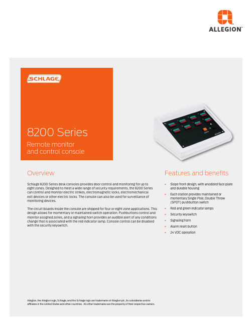
OverviewSchlage 8200 Series desk consoles provides door control and monitoring for up to eight zones. Designed to meet a wide range of security requirements, the 8200 Series can control and monitor electric strikes, electromagnetic locks, electromechanicalexit devices or other electric locks. The console can also be used for surveillance of monitoring devices.The circuit boards inside the console are shipped for four or eight zone applications. This design allows for momentary or maintained switch operation. Pushbuttons control and monitor assigned zones, and a signaling horn provides an audible alert of any conditions change that is associated with the red indicator lamp. Console control can be disabled with the security keyswitch.Features and benefits §Slope front design, with anodized face plate and durable housing§Each station provides maintained or momentary Single Pole, Double Throw(SPDT) pushbutton switch§Red and green indicator lamps§Security keyswitch§Signaling horn§Alarm reset button§24 VDC operationAllegion, the Allegion logo, Schlage, and the Schlage logo are trademarks of Allegion plc, its subsidiaries and/or affiliates in the United States and other countries. All other trademarks are the property of their respective owners.About AllegionAllegion (NYSE: ALLE) is a global pioneer in seamless access, with leading brands like CISA ®, Interflex ®, LCN ®, Schlage ®, SimonsVoss ® and Von Duprin ®. Focusing on security around the door and adjacent areas, Allegion secures people and assets with a range of solutions for homes, businesses, schools and institutions. Allegion had $2.7 billion in revenue in 2020, and its security products are sold around the world. For more, visit Ordering informationLast digit indicates number of zones4 station console 8 station console 8204 8208Pushbutton function§Select pushbutton function by zone.§Select M (momentary) or A (alternate action, maintain) for each zone.1 2 3 4 5 6 7 8 §8204 _ _ _ _ §8208__ _ _ _ _ _ _AccessoriesField installable push buttons§8200MS – Momentary switch assembly§8200AS– Alternate action (maintained) switch assemblySpecificationsSwitches (momentary or maintained) 1.0 amps 24 VDC Lamps #85 red/green 40 mA @24 VDC Terminal block 18/22 gauge wireAlarm output 0.5 amps @ 24 VDC (breaker protected)Temperature range 32° to 120°F (0° to 49°C)Input voltage24 VDC, +/- 15%System design guideThere are a number of applications where an 8200 Series Console is used to monitor and control multiple door openings. It is ideal for use at a guard or nurse station. (An example of a riser diagram for a two door nurse’s station console is shown below.)Description of system operationTwo single doors, each normally closed and secured by a magnetic lock. Magnetic lock to include Magnetic Bond Sensor (MBS) for remote monitoring of secure/not-secure condition. Legal access to be provided by keypad system. Egress to be provided by touch sensitive exit bars. Remote control and monitoring to be by a slope front desktop console. Each of two stations shall provide a momentary pushbutton switch for legal release, a red indicator for “not-secure” condition and a green indicator for “secure” condition.Riser diagram© 2022 Allegion 005004, Rev. 02//us。
8200-Series 桌面控制台操作指南说明书

8200-Series Desk Console*82000*82000Installation Instructions for Single Locks2LIST OF PARTS• Pushbuttons/Hole Plugs• Maintained or Momentary Pushbutton Assembly*• Hole Plug*•Keyswitch Keys (2)* Each console will have installed any combination of these in the switch/hole plug positionSPECIFICATIONS/FUNCTIONPower• 24 VDC ± 15%• 50 milliamp internal console excluding lamps • For UL applications, the power source shall be a UL294 listed class 2 (power limited) power supply Pushbutton (Momentary or Maintained)• 1 Amp, 24 VDCLamps (Green or Red)• 0.04 Amps @ 24 VDC (#85 lamp)T erminal Blocks • Maximum of 14 Ga wire, 18-22 recommended • Rated torque/screw size 0.50 Nm/M³Alarm Output • 0.5 Amp @ 24 VDC common to all zones, protected by automatically resetable breaker Keyswitch• Off (CCW) – Powers NC (FS) outputs and removes power from NO (FSE) outputs by breaking pushbutton common. Powering NC contacts can be field modified to eliminate this feature - see User Selectable Options • ON (CW) – Powers pushbutton common and allows the pushbuttons to have full control over the zone Reset Button • Momentary pushbutton that resets the internal latching horn and the Alarm Output that has been triggered by voltage on the RED terminal T emperature Range • 32°F – 120°FMaintained or Momentary Pushbutton Assemby*Hole Plug*Keyswitch Keys (2)3Wiring Examples(LIGHT , SOUNDER ETC.)MAX. LOAD 1/2A @24VDC• When pushbutton is depressed, the CHEXIT device is disarmed and the GREEN light is on.• When pushbutton is released, the CHEXIT is armed and the pushbutton light is off.• If the pushbar is depressed while the CHEXIT is armed, the RED light will come on and the alarm will sound.Typical L1910 WiringRED BLKBLUVIO GRN HORNL1910YELRED BLU GRN RED C NO NCTB(1-3)TB 9DESK CONSOLEL1910. DPS24VDC POWER SUPPL YDOOR POS. SWITCHSHOWN WITH DOOR CLOSEDGND +24•When pushbutton is depressed, the L1910 horn isdisarmed (passage through door allowed) and GREEN light in pushbutton will come on.•When pushbutton is released, the L1910 horn is armed (passage through door will sound alarm) and RED light in pushbutton will come on.Typical Magnetic Lock with DPS & HFS Option WiringDESK CONSOLEMAGNETIC LOCK24VDC POWER SUPPL YDOOR POSITION SWITCH HOLD FORCE SENSORMAGNETICLOCKGRN RED C NONCGND +24NO CC NC NC NC V+V-TB(1-8)TB 9• When pushbutton is depressed, the magnetic lock is unlocked and the GREEN light will come on.• When the pushbutton is released, the magnetic lock is locked and the pushbutton light is off.•If the door is forced open while the magnetic lock is locked, the RED light will come on and the alarm will sound.TYPICAL EXTERNAL HORN WIRING4Typical 6000 Series Electric Strike WiringELECT STRIKE• When pushbutton is depressed, the electric strike is unlocked and the GREEN light is on.• When pushbutton is released, the strike is locked and the pushbutton light is off.•If the door is forced open while the strike is locked, the RED light will come on and the alarm will sound.Typical EL Device WiringDESK CONSOLE24VDC POWER SUPPL YEL DEVICEEL DEVICEGRN RED C NO NCGND +24TB(1-8)TB 9•When pushbutton is depressed, the EL devices are unlocked and the GREEN light in the pushbutton will come on.•When pushbutton is released, the EL devices are locked and the pushbutton light is off.•Refer to PS914 x 900-2RS PCB instructions for proper wiring instructions for the EL device.INSTALLATION/WIRING1REMOVE ALL FOUR (4) SCREWS52 REMOVE I/O PANEL AND DRILL HOLE FOR WIRE USEDIf required, use a strain relief or cable connector for wires.Conduit SizeDrill Size Z\x ”M\,”C\v ”1Z\,”3 REASSEMBLE BOX4 REMOVE ALL FOUR (4) FACEPLATE SCREWSI/O PanelWiring65 CONNECT PROPER GAUGE WIRE TO THE APPROPRIATE TERMINALS AS REQUIRED• TB1 corresponds to pushbutton 1, TB2 to pushbutton 2, etc.• Keep excess wire out of console for easier installation.• For ease of wiring, faceplate with pushbuttons can be unplugged and reconnected later.6 RECONNECT PUSHBUTTONS, IF NEEDEDMake sure they are properly polarized, then replace faceplate and secure screws.TROUBLESHOOTINGPushbutton contacts and lights do not work• Check that the pushbutton connector is fullyseated in the proper plugLamp does not work• Check for 24 VDC on the RED or GRN terminal• Replace the bulb - see MaintenanceMAINTENANCELamp ReplacingReplace with #85 lamp as shown belowReplacing/Adding a Pushbutton Pushbuttons can be replaced, changed (either from maintained to momentary, or viceversa) or added. With the faceplate removed, using a small flathead screwdriver, removethe two pushbutton holder springs. Remove the pushbutton assembly from the faceplate.Note: Make sure pushbuttons are plugged into the proper zones per T able 1 and the redlens is in the lower position.Cleaning Use a mild cleaner to clean the console off.Do not spray directly onto the face.7USER SELECTABLE OPTIONS1. Pushbutton common isolation: Normally all pushbutton commons are connected to +PWR INPUT whenkeyswitch is ON. To isolate any pushbutton from +PWR INPUT voltage, cut proper diode (CR20-27) see Table 1.2. NC contact control: When the keyswitch is in the OFF position, the NC output is powered (pushbutton has nocontrol). T o control NC contacts, select and cut proper diode (CR9-16), see Table 1.3. Red terminal latch disable: Application of 24 VDC to the RED terminal not only lights the RED light, but latches theinternal buzzer and 24 VDC on the Alarm Output. If the latching feature is not desired on a zone, cut proper diode (CR1-8), see Table 1.TYPICAL ONE ZONE BUTTON++__0PWR INPUTGRNREDCNO (FAIL SECURE)NC (FAIL SAFE)ALARM OUTPUTTable 1Pushbutton (or TB#)12345678PCB PlugP1P2P3P4P5P6P7P8Pushbutton Common Isolation CR20CR21CR22CR23CR24CR25CR26CR27NC Contact Control CR9CR10CR11CR12CR13CR14CR15CR16Red Term. Latch DisableCR1CR2CR3CR4CR5CR6CR7CR8© Allegion 2014Printed in U.S.A.82000 Rev. 12/14-e。
卡利福音频系统8200用户手册说明书
help. NOTE: Shielded cables may be required to be used with this unit to ensure compliance with the Class B FCC limits.
1
1. IMPORTANT SAFETY INSTRUCTIONS
Before using this product, read the instruction manual for important safety information. Please retain this manual for future reference and warranty information. Troubleshooting & Servicing Do not attempt to service or repair the device yourself. Refer all servicing to qualified service personnel. Do not attempt to modify the device in any way. Doing so could invalidate your warranty. Moisture and heat sources Do not use this apparatus near water (for example, sinks, baths, pools) or expose it to rain, moisture, dripping or splashing liquids. Do not expose the unit to high temperatures, high humidity or direct sunlight. Cleaning When cleaning the device, please use a soft, dry cloth. Never use benzene, paint-thinner, or other chemicals on the device. Location Place the device in stable location, so it will not fall causing damage to the device or bodily harm. Intended use The product may only be used with the original parts intended for it. The product may only be used in closed and dry rooms. The intended use includes adherence to the specified installation instructions. The manufacturer accepts no liability for damage arising due to improper use.
LE系列电泵使用和维护手册说明书

Manual del PropietarioElectrobomba centrifuga LE LE 14-20LE 25-32LE 40-50En este manual están indicadas las instrucciones para el uso y mantenimiento de las electro-bombas de la serie s electrobombas mencionadas son del tipo centrífugas monoblock, para elevar el agua.La utilización de la bomba está subordinada a las directivas de la legislación local.Antes de instalar y utilizar la bomba leer con atención las siguientes instrucciones.El fabricante declina toda responsabilidad en caso de incidentes o daños debidos a negligen-cia o incumplimiento de las instrucciones descriptas en este manual,o bajo condiciones dife-rentes de aquellas indicadas en la placa de las características.T ambien declina toda responsabilidad por los daños causados por un uso impropio de la electrobomba.Descripción de la electrobombaLa electrobomba serie LE se entrega embalada en cajas de cartón,junto al manual de ins-trucciones correspondiente,lista para ser instalada.En caso de almacenaje,no colocar peso u otras cajas encima de la misma.SeguridadAntes de realizar cualquier control o mantenimiento,cortar la tensión de la instalación y desconectar el enchufe del tomacorrientes.La bomba tiene que funcionar con agua limpia o líquidos químicamente no agresivos y no es idónea para bombear líquidos inflamables o para trabajar en locales con peligro de explosión. Las electrobombas cumplen con las normasinternacionales IEC 60335-1,IEC 60335-2-41,incluídas las últimas modificaciones,sobre las condiciones de seguridad para los aparatos electrodomésticos y las normas particulares,apli-cables a estos productos.Previa instalación,asegurese que la red de alimentación tenga co-nexión a tierra conforme a la normativa.Dado que la alimentación de la bomba es eléctrica,evite el contacto entre la alimentación eléctrica y el líquido por bombearse.No modifique lo componentes de la electrobomba.Reparar o hacer reparar la bomba por personal no autorizado por el fabricante,significa perder la garantía y trabajar con aparatos inseguros y peligrosos.Inspección preliminarExtraer de la caja y verificar la integridad de la misma.T ambién verifique que los datos de la placa correspondan a las características deseadas. Ante cualquier anomalia comuníquese inmediatamente con el proveedor indicando el tipo de defecto encontrado.Atención:no utilice la electrobomba si tiene dudas sobre la seguridad de la misma.Condiciones de empleoLa electrobomba debe utilizarse respetando las siguientes condiciones:• T emperatura máxima del líquido:hasta +40ºC (para todos los modelas LE)• Densidad máxima del líquido bombeado:1Kg/dm3• pH del líquido:6/8• Variación de tensión permitida +/–5%,cuya tensión monofásica nominal es 220v-50Hz • Indice de protección:IP55• Asegúrese que la bomba trabaje en el rango de funcionamiento nominal.• El funcionamiento de la bomba con la esclusa cerrada (caudal cero),no debe exceder los 2 (dos) minutos.• Nivel de presión acústica inferior a los valores máximos permitidos:menor 77db. InstalaciónLa instalación es una operación que puede resultar algo compleja.Por lo tanto se sugiere que sea realizada por instaladores competentes y autorizados. Atención:durante la instalación aplicar todas las disposiciones de seguridad emanadas por los organismos competentes y dictadas por el sentido común.T odas las partes vivas (con tensión) tienen que estar inaccesibles.La conexión a tierra debe estar conectada al cableado fijo.En la instalación eléctrica debe incorporarse un interruptor bipolar con una separación en-tre contactos de al menos 3 milímetros.Las partes que incorporan componentes eléctricos deben instalarse en forma fija.Instalar la bomba en un lugar seco y bien ventilado.Fijar la bomba con las tuercas específicas sobre una superficie plana y sólida con el fin de evitar vibraciones.Se aconseja la instalación en posición horizontal.En la aspiración,el diámetro del tubo no debe ser inferior al diámetro de la boca de la bomba.Asegúrese que el tubo esté completamente sellado contra la entrada de aire y que perma-nezca sumergido en el líquido que debe bombear al menos 20cm,con la finalidad de evitar la formación de remolinos.El diámetro del tubo de impulsión condiciona el caudal y la pre-sión disponibles en los puntos de utilización.Prever algún tipo de fijación para las tuberías de forma que no se transmita ningún tipode rebaba u obstrucción que reduzca la sección útil de paso del fluido.Enroscar o fijar las tuberías en las respectivas bocas sin forzar demasiado para evitar daños.Cebado de la bombaEl funcionamiento en seco de la electrobomba,causa daños al sello mecánico.Esta operación se realiza a través del tapón de cebado,llenando la bomba y también la tu-bería de succión,con el líquido que se desea bombear.Finalizada la operación,roscar nuevamente el tapón y encender la bomba.Se recomienda colocar una válvula de retención en el extremo inferior de la tubería de as-piración,para evitar que se descebe.El cebado debe repetirse cada vez que la bomba quede sin funcionar por largos períodos. Conexiones eléctricasLas electrobombas se entregan listas para ser conectadas.Atención:es precaución del instalador efectuar la conexión respetando las normas vigentes en el país de instalación.Antes de efectuar la conexión asegurarse que no haya tensión en los cables de alimentación.Verificar la correspondencia entre los datos de la placa y los valores nominales de la línea. Efectuar la conexión (asegurándose de la existencia de un circuito de tierra eficaz) según el esquema indicado en el interior de la tapa de bornes o en la placa.El conductor de tierra tiene que ser más largo que los conductores de fase y tiene que ser el primero a ser conectado durante el montaje y el último a ser desconectado durante el desmontaje.Se recomienda instalar siempre un interruptor diferencial con una sensibilidad de fuga de 30mA.En las electrobombas serie LE,el motor está protegido de las sobrecargas mediante un dis-positivo térmico (salvamotor) insertado en el bobinado.En las electrobombas LE,el sentido de rotación ya está prefijado de fábrica y no se puede invertir.MantenimientoAntes de cualquier operación,asegúrese que la tensión esté desconectada y que no haya posibilidad de conexiones accidentales.Reparar o hacer reparar la bomba a personal no autorizado por el fabricante significa per-der la garantía y correr el riesgo de operar con un aparato inseguro y potencialmente peli-groso.Atención:cada modificación puede hacer disminuir el rendimiento y poner en peligro a personas y/o cosas.Las bombas no requieren ningún tipo de mantenimiento siempre que se tomen las siguientes precauciones.En el caso de que el eje no gire libremente,proceder a desbloquearlo mediante un destornillador accionando el eje desde el lado del ventilador.Si esto no fuese suficiente desmontar el cuerpo bomba y proceder a remover eventuales inscrustaciones.LE 14 / 20LE 25 / 32LE 40 / 50Detección de fallasDefectos Causas SoluciónEl motor no se pone Falta de Alimentación Controle la tensión de la líneaen marcha Controle las conexiones eléctricasRodete bloqueado Desmonte el rodete y límpieloDefecto en la parte Diríjase al proveedoreléctricaEl motor gira sin bombear Altura de aspiración Acerque la bomba al nivelagua,o suministra poco excesiva estático del aguacaudalAire en la aspiración Verifique la estanqueidad deltubo de aspiración.Interviene el interruptor El motor se recalienta Verifique la tensión de alimentación automático de máxima y la ventilación del motor(protector térmico)Rodete bloqueado Desbloquear el rotorDeclaración de ConformidadElektrim S.R.L.,declara bajo su exclusiva responsabilidad que los productos de las series LE,a los cuales se refiere esta declaración,son producidos y comercializados conforme a las nor-mas ,comprendidas en últimas modificaciones,y a la respectiva legislación nacional que las incorpora,sobre:IEC 60335-1,IEC 60335-2-41,IEC 55014,IEC 55014-2Luis María Drago 178 I B1876AHD Bernal I Buenos Aires I Argentina T el:(54-11)4251-3507 I *********************.ar I .ar En los mejores negocios de piscinas del pais。
Philips 8200系列4K UHD LED Android TV产品说明书
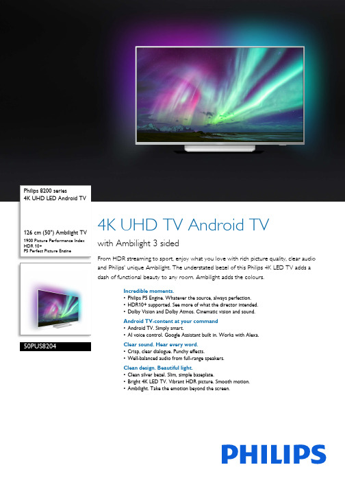
Philips 8200 series4K UHD LED Android TV126 cm (50") Ambilight TV 1900 Picture Performance IndexHDR 10+P5 Perfect Picture Engine50PUS82044K UHD TV Android TVwith Ambilight 3 sidedFrom HDR streaming to sport, enjoy what you love with rich picture quality, clear audio and Philips' unique Ambilight. The understated bezel of this Philips 4K LED TV adds a dash of functional beauty to any room. Ambilight adds the colours.Incredible moments.•Philips P5 Engine. Whatever the source, always perfection.•HDR10+ supported. See more of what the director intended.•Dolby Vision and Dolby Atmos. Cinematic vision and sound.Android TV-content at your command•Android TV. Simply smart.•AI voice control. Google Assistant built in. Works with Alexa.Clear sound. Hear every word.•Crisp, clear dialogue. Punchy effects.•Well-balanced audio from full-range speakers.Clean design. Beautiful light.•Clean silver bezel. Slim, simple baseplate.•Bright 4K LED TV. Vibrant HDR picture. Smooth motion.•Ambilight. Take the emotion beyond the screen.HighlightsAmbilight 3 sidedWith Philips Ambilight, movies and games feel more immersive. Music gets a light show. And your screen will feel bigger than it is. Intelligent LEDs around the edges of the TV cast on-screen colours onto the walls and into the room, in real time. You get perfectly tuned ambient lighting. And one more reason to love your TV.4K UHDBright 4K LED TV. Vibrant HDR picture. Smooth motion. A Philips 4K UHD TV brings content to life with rich colours and crisp contrast. Images have more depth and motion is smooth. Movies, shows, games and more look great no matter the source.P5 Perfect Picture EngineThe Philips P5 Perfect Picture Engine delivers an image as brilliant as the content you love.Details have noticeably more depth. Colours are vivid, while skin tones look natural.Contrast is so crisp you'll feel every detail. And motion is so smooth that you'll never lose sight of the ball, no matter how fast the play.Dolby Vision and Dolby AtmosSupport for Dolby's premium sound and video formats means the HDR content you watch will look—and sound—gloriously real.Whether it's the latest streaming series or a Blu-Ray disc set, you'll enjoy contrast, brightness and colour that reflect the director's original intentions. And hearspacious sound with clarity, detail and depth.HDR10+ supportedYour Philips TV is primed to get the most out of the HDR10+ video format. Contrast, colour and brightness levels are adjusted from frame to frame. Whether it's a must-watch series or the new blockbuster, shadows will be deeper. Bright surfaces will shine. Colours will be truer.Android TV.Make your Philips Android TV your own. If it's all about Amazon and YouTube this week and Rakuten TV and Netflix next week - no problem. A clear, intuitive interface lets you put the content you love front and centre. Easily pick up where you left off in the latest series, or check out the new movie releases.AI voice control.Control your Philips Android TV with your voice. Want to play a game, watch Netflix or find content and apps in the Google Play store? Just tell your TV. You can even command all Google Assistant-compatible smart home devices, like dimming the lights and setting the thermostat on movie night. Without leaving the sofa. The days of searching for the TV remote are over. Now you can use your voice to control your Philips smart TV via Alexa-enabled devices, like Amazon Echo. Turn your TV on, change the channel, switch to your gaming console and more with Alexa.Clean designClean silver bezel. Slim, simple baseplate.Punchy effectsCrisp, clear dialogue. Punchy effects.Well-balanced audioWell-balanced audio from full-range speakers.Ambilight•Ambilight Features: Built-in Ambilight+hue, Ambilight Music, Game Mode, Wall colour adaptive, Lounge mode•Ambilight Version: 3 sidedPicture/Display•Aspect ratio: 16:9•Diagonal screen size (metric): 126 cm •Display: 4K Ultra HD LED•Panel resolution: 3840 x 2160•Picture engine: P5 Perfect Picture Engine•Picture enhancement: Wide Colour Gamut 90%DCI/P3, Micro Dimming Pro, Ultra Resolution,Dolby Vision, HDR10+•Diagonal screen size (inch): 50 inchSupported Display Resolution•Computer inputs on all HDMI: up to 4K UHD3840 x 2160 @60 Hz, HDR supported, HDR10/HLG•Video inputs on all HDMI: up to 4K UHD 3840 x2160 @60 Hz, HDR supported, HDR10/HLG(Hybrid Log Gamma), HDR10+/Dolby VisionTuner/Reception/Transmission•Digital TV: DVB-T/T2/T2-HD/C/S/S2•Video Playback: NTSC, PAL, SECAM•MPEG Support: MPEG2, MPEG4•TV Programme guide*: 8-day ElectronicProgramme Guide•Signal strength indicationIssue date 2023-10-21 Version: 4.0.1EAN: 87 18863 02113 2© 2023 Koninklijke Philips N.V.All Rights reserved.Specifications are subject to change without notice. Trademarks are the property of Koninklijke Philips N.V. or their respective owners.•Teletext: 1000 page Hypertext•HEVC supportAndroid TV•OS: Android TV™ 9 (Pie)•Pre-installed apps: Google Play Movies*, Google Play Music*, Google Search, YouTube •Memory size (Flash): 16 GB*Smart TV Features•User Interaction: SimplyShare•Interactive TV:HbbTV•Programme: Pause TV, USB recording*•Ease of Installation: Auto detect Philips devices, Device connection wizard, Network installation wizard, Settings assistant wizard•Ease of Use: One-stop smart menu button, On-screen user manual•Firmware upgradeable: Firmware auto upgrade wizard, Firmware upgradeable via USB, Online firmware upgrade•Screen Format Adjustments: Basic - Fill Screen, Fit to screen, Advance - Shift, Zoom, stretch, Wide screen•Philips TV Remote app*: Apps, Channels, Control, NowOnTV, TV Guide, Video On Demand •Remote Control: with Keyboard, with Voice Multimedia Applications•Video Playback Formats: Containers: AVI, MKV, H264/MPEG-4 AVC, MPEG-1, MPEG-2, MPEG-4, WMV9/VC1, HEVC (H.265), VP9•Music Playback Formats: AAC, MP3, WAV, WMA (v2 up to v9.2), WMA-PRO (v9 and v10)•Subtitles Formats Support: .SRT, .SUB, .TXT, .SMI •Picture Playback Formats: JPEG, BMP, GIF, PNG, 360 photo, HEIFProcessing•Processing Power: Quad CoreSound•Output power (RMS): 20 W•Speaker configuration: 2 x 10 W full-range speaker •Sound Enhancement: 5 Band Equalizer, A.I. Sound, Clear Dialogue, Dolby Bass Enhancement, Dolby Volume Leveller, Night mode, Dolby Atmos®Connectivity•Number of HDMI connections: 4•HDMI features: 4K, Audio Return Channel •Number of components in (YPbPr): 1•EasyLink (HDMI-CEC): Remote control pass-through, System audio control, System standby,One touch play•Number of USBs: 2•Wireless connection: Bluetooth 4.2, Wi-Fi802.11ac, 2 x 2, Dual band•Other connections: Common Interface Plus (CI+),Digital audio out (optical), Satellite Connector,Ethernet-LAN RJ-45, Audio L/R in, Headphone out•HDCP 2.2: Yes on all HDMIPower•Mains power: AC 220 - 240 V 50/60 Hz•Ambient temperature: 5°C to 35°C•Standby power consumption: <0.3 W•Energy Label Class: A•EU Energy Label power: 81 W•Power Saving Features: Auto switch-off timer,Light sensor, Picture mute (for radio), Eco mode•Off mode power consumption: N/A•Annual energy consumption: 119 kW·h•Presence of lead: Yes*•Mercury content: 0 mgAccessories•Included batteries: 2 x AAA Batteries•Included Accessories: Legal and safety brochure,Mini-jack to L/R cable, Mini-jack to YPbPr cable,Power cord, Quick start guide (x 1), RemoteControl, Tabletop standColour & Finish•TV Front: Light SilverDimensions•Set Width: 1119.8 mm•Set Height: 651.8 mm•Set Depth: 77.7 mm•Product weight: 14.5 kg•Set width (with stand): 1119.8 mm•Set height (with stand): 696.8 mm•Set depth (with stand): 207.0 mm•Product weight (+stand): 16.1 kg•Box width: 1240.0 mm•Box height: 850.0 mm•Box depth: 174.0 mm•Weight incl. Packaging: 20.0 kg•Stand width: 520.0 mm•Stand height: 45.0 mm•Stand depth: 251.5 mm•Wall-mount compatible: 300 x 200 mm*EPG and actual visibility (up to 8 days) is country- and operator-dependent.*Android App offerings vary per country. For more details please visityour local Google Play Store.*Energy consumption in kWh per year based on the powerconsumption of the television operating 4 hours per day for 365days. The actual energy consumption will depend on how thetelevision is used.*The TV supports DVB reception for 'Free to air' broadcast. SpecificDVB operators may not be supported. An up to date list can befound in the FAQ section of the Philips support website. For someoperators Conditional Access and subscription are required.Contact your operator for more information.*Philips TV Remote app and related functionalities vary per TV model,operator and country, as well as smart device model and OS. Formore details please visit: /TVRemoteapp.*Smart TV app availability varies per TV model and country. For moredetails please visit: /smarttv.*USB recording for digital channels only, recordings may be limited bybroadcast copy protection (CI+). Country and channel restrictionsmay apply.*Please note that your Amazon Apps may not always be available inyour country. (Currently Amazon apps works only in the UK,Germany and Austria)*This television contains lead only in certain parts or componentswhere no technology alternatives exist in accordance with existingexemption clauses under the RoHS Directive.*Its functionality is subject to ChromeCast built-in apps and smartdevices. For more details, please visit ChromeCast built-in productpages.。
Philips 8200 4K UHD LED Android TV 说明书

Philips 8200 series4K UHD LED Android TV126 cm (50")Major HDR formats supported P5 Perfect Picture Engine50PUT82154K UHD LED Android TVwith P5 Perfect Picture EngineFamily movie night. The big game. Whatever the occasion, settle down to superb picture quality and great sound. This TV makes all your content look great,Slim TV. Beautiful light.•Bright 4K LED TV. Vibrant HDR picture. Smooth motion.Android TV-content at your command•Google Play store and Philips app gallery. More to love.•Google Assistant. Control the TV with your voice.•Android TV. Simply smart.•Voice control. Google Assistant built-in. Works with Alexa.•DTS Play-Fi. Multi-room audio.Smooth motion. Real color. Incredible depth.•Philips P5 Engine. Whatever the source, always perfection.•Dolby Vision and Dolby Atmos. Cinematic vision and sound.Crisp sound. Hear every word.•Well-balanced audio. Crisp, clear dialogue. Punchy effects.HighlightsP5 Perfect Picture EngineThe Philips P5 engine delivers a picture as brilliant as the content you love. Details have noticeably more depth. Colors are vivid, while skin tones look natural. Contrast is so crisp you'll feel every detail. Motion is perfectly smooth.Dolby Vision and Dolby AtmosSupport for Dolby's premium sound and video formats means the HDR content you watch will look-and sound-gloriously real. Whether it's the latest streaming series or a Blu-Ray disc set, you'll enjoy contrast, brightness, and color that reflect the director's original intentions. And hear spacious sound with clarity, detail, and depth.TV ContentGo beyond traditional TV programming with Google Play Store and Philips App Gallery.Experience endless movies, TV, music, apps and games online. More to love.4K UHDBright 4K LED TV. Vibrant HDR picture. Smooth motion.A Philips 4K UHD TV brings content to life with rich colors and crispcontrast. Images have more depth, and motion is smooth. Movies, shows, games, and more look great no matter the source.Android TVMake your Philips Android TV your own. If it's all about Amazon and YouTube this week, and Netflix next week-no problem. A clear,intuitive interface lets you put the content you love front and center. Easily pick up where you left off in the latest series, or check out the new movie releases.Google AssistantControl your Philips Android TV with your voice. Want to play a game, watch Netflix, or find content and apps in the Google Play store? Just tell your TV. You can even command all Google Assistant-compatible smart home devices-like dimming the lights and setting the thermostat on movie night. Without leaving the sofa.Voice assistantControl your Philips Android TV with your voice. Want to play a game, watch Netflix, or find content and apps in the Google Play store? Just tell your TV. You can even command all Google Assistant-compatible smart home devices, like dimming the lights and setting the thermostat on movie night. Without leaving the sofa. The days of searching for the TV remote are over. Now you can use your voice to control your Philips smart TV via Alexa-enabled devices, like Amazon Echo. Turn your TV on, change the channel, switch to your gaming console and more with Alexa.Well-balanced audioWell-balanced audio. Crisp, clear dialogue. Punchy effects.DTS Play-FiWith DTS Play-Fi on your Philips TV you can connect to compatible speakers in any room. Got wireless speakers in the kitchen? Listen to the movie while you make a snack, or keep up with the sports commentary while you geteveryone a drink.Issue date 2023-08-21 Version: 6.1.1EAN: 87 18863 02569 7© 2023 Koninklijke Philips N.V.All Rights reserved.Specifications are subject to change without notice. Trademarks are the property of Koninklijke Philips N.V. or their respective owners.SpecificationsPicture/Display•Aspect ratio: 16:9•Display: 4K Ultra HD LED•Panel resolution: 3840x2160•Picture engine: P5 Perfect Picture Engine •Picture enhancement: Ultra Resolution, Micro Dimming ProSupported Display Resolution •Computer inputs on all HDMI: HDR supported, HDR10/ HLG, up to 4K UHD 3840x2160 @60Hz •Video inputs on all HDMI: up to 4K UHD3840x2160@60Hz, HDR10/HLG (Hybrid Log Gamma), HDR10+/Dolby VisionTuner/Reception/Transmission•Digital TV: DVB-T/T2•Video Playback: NTSC, PAL, SECAM•MPEG Support: MPEG2, MPEG4•TV Program guide*: 8 day Electronic Program Guide•Signal strength indication•HEVC supportAndroid TV•OS: Android TV™ 9 (Pie)•Pre-installed apps: Google Play Movies*, Google Play Music*, Google Search, YouTube •Memory size(Flash): 16GB*•Memory size to install apps: 5GBSmart TV•SmartTV apps*: NetflixSmart TV Features•User Interaction: SimplyShare•Program: Pause TV, USB recording*•Ease of Installation: Auto detect Philips devices, Network installation wizard, Settings assistant wizard•Ease of Use: One-stop smart menu button, Onscreen usermanual•Firmware upgradeable: Firmware auto upgrade wizard, Firmware upgradeable via USB, Online firmware upgrade•Screen Format Adjustments: Basic - Fill Screen, Fit to screen, Advance - Shift, Zoom, stretch •Philips TV Remote app*: Apps, Channels, Control, TV Guide Multimedia Applications•Video Playback Formats: Containers: AVI, MKV,H264/MPEG-4 AVC, MPEG-1, MPEG-2, MPEG-4,WMV9/VC1, HEVC (H.265), VP9•Music Playback Formats: AAC, MP3, WAV, WMA(v2 up to v9.2), WMA-PRO (v9 and v10)•Subtitles Formats Support: .SRT, .SUB, .TXT, .SMI•Picture Playback Formats: JPEG, BMP, GIF, PNG,360 photo, HEIFProcessing•Processing Power: Quad CoreSound•Output power (RMS): 16W•Speaker configuration: 2x8W full range speaker•Sound Enhancement: Auto Volume Leveler, DolbyAtmos, Clear Sound, Smart SoundConnectivity•Number of HDMI connections: 4•HDMI features: 4K, Audio Return Channel•EasyLink (HDMI-CEC): Remote control pass-through, System audio control, System standby,One touch play•Number of USBs: 2•Wireless connection: Bluetooth 4.2, Wi-Fi802.11n, 2x2, Dual band•Other connections: Digital audio out (optical),Ethernet-LAN RJ-45, Headphone out•HDCP 2.2: Yes on all HDMIPower•Mains power: AC 220 - 240 V 50/60Hz•Ambient temperature: 5 °C to 35 °C•Power Saving Features: Auto switch-off timer,Picture mute (for radio), Light sensorAccessories•Included accessories: Remote Control, Quick startguide, Legal and safety brochure, Power cord,Table top stand•Included batteries: 2 x AAA BatteriesDimensions•Set Width: 1113 mm•Set Height: 660.1 mm•Set Depth: 87.2 mm•Product weight: 11.1 kg•Set width (with stand): 1113 mm•Set height (with stand): 717 mm•Set depth (with stand): 269 mm•Product weight (+stand): 11.38 kg•Box width: 1240 mm•Box height: 800 mm•Box depth: 160 mm•Weight incl. Packaging: 15.6 kg•Wall mount compatible: 200 x 200 mm*EPG and actual visibility (up to 8 days) is country and operatordependent.*Android App offerings vary per country. For more details please visityour local Google Play Store.*The TV supports DVB reception for 'Free to air' broadcast. SpecificDVB operators may not be supported. An up to date list can befound in the FAQ section of the Philips support website. For someoperators Conditional Access and subscripction are required.Contact your operator for more information.*Philips TV Remote app and related functionalities vary per TV model,operator, and country, as well as smart device model and OS. Formore details please visit: /TVRemoteapp.*Smart TV app offerings vary per TV model and country. For moredetails please visit: /smarttv.*Please note that your Amazon Apps may not always be available inyour country. (Currently Amazon apps works only in UK, Germany,Austria)*Its functionality is subject to ChromeCast built-in apps and smartdevises. For more details, please visit ChromeCast built-in productpages.*Image depicted on the website are non-contractual pictures. Pleasealways refer to the actual TV that are sold in the retail or stores.。
- 1、下载文档前请自行甄别文档内容的完整性,平台不提供额外的编辑、内容补充、找答案等附加服务。
- 2、"仅部分预览"的文档,不可在线预览部分如存在完整性等问题,可反馈申请退款(可完整预览的文档不适用该条件!)。
- 3、如文档侵犯您的权益,请联系客服反馈,我们会尽快为您处理(人工客服工作时间:9:00-18:30)。
1.1 连接方法 ・・・・・・・・・・・・・・・・・・・・・・・・ 7 测试RS-232C时的连接 ・・・・・・・・・・・・・・・・・・・・ 7 测试RS-422、RS-485时的连接 ・・・・・・・・・・・・・・・・ 8 测试其他接口时的连接 ・・・・・・・・・・・・・・・・・・・・ 8 1.2 测试流程 ・・・・・・・・・・・・・・・・・・・・・・・・ 9 开机 ・・・・・・・・・・・・・・・・・・・・・・・・・・・・ 9 主菜单画面 ・・・・・・・・・・・・・・・・・・・・・・・・・ 9 参数设置 ・・・・・・・・・・・・・・・・・・・・・・・・・・ 9 连接测试对象 ・・・・・・・・・・・・・・・・・・・・・・・ 10 开始测试 ・・・・・・・・・・・・・・・・・・・・・・・・・ 10 结束测试 ・・・・・・・・・・・・・・・・・・・・・・・・・ 10 使用测试数据 ・・・・・・・・・・・・・・・・・・・・・・・ 10 关闭电源 ・・・・・・・・・・・・・・・・・・・・・・・・・ 10
第 2 章 监听功能 ・・・・・・・・・・・・・・・・・・・・・・・・・・・・・ 11
2.1 在线监听功能(ONLINE) ・・・・・・・・・・・・・・・・・ 11 设置 ・・・・・・・・・・・・・・・・・・・・・・・・・・・ 11 操作 ・・・・・・・・・・・・・・・・・・・・・・・・・・・ 11 暂停 ・・・・・・・・・・・・・・・・・・・・・・・・・・・ 12 停止测试动作 ・・・・・・・・・・・・・・・・・・・・・・・ 12 滚屏 ・・・・・・・・・・・・・・・・・・・・・・・・・・・ 12 跳转 ・・・・・・・・・・・・・・・・・・・・・・・・・・・ 12 在线监听实例 ・・・・・・・・・・・・・・・・・・・・・・・ 13 2.2 信号电压以及延迟时间的测试功能(AI&DELAY) ・・・・・・・ 18
第 3 章 仿真功能 ・・・・・・・・・・・・・・・・・・・・・・・・・・・・・ 22
3.1 仿真的准备 ・・・・・・・・・・・・・・・・・・・・・・ 23 发送数据用表格(Data send table)・・・・・・・・・・・・・・・ 23 方便的数据编辑方法:复制、删除、固定发送数据的输入 ・・・・ 26 编辑选项:复制数据表、复制缓冲内存、模式重复(数据文件) ・ 27 3.2 手动仿真模式(MANUAL) ・・・・・・・・・・・・・・・・ 30 设置 ・・・・・・・・・・・・・・・・・・・・・・・・・・・ 30 操作 ・・・・・・・・・・・・・・・・・・・・・・・・・・・ 30 3.3 通信再现测试(BUFFER) ・・・・・・・・・・・・・・・・・ 32 准备 ・・・・・・・・・・・・・・・・・・・・・・・・・・・ 32 设置 ・・・・・・・・・・・・・・・・・・・・・・・・・・・ 32 动作 ・・・・・・・・・・・・・・・・・・・・・・・・・・・ 33 3.4 流控制测试(FLOW) ・・・・・・・・・・・・・・・・・・・ 34 设置 ・・・・・・・・・・・・・・・・・・・・・・・・・・・ 34 动作 ・・・・・・・・・・・・・・・・・・・・・・・・・・・ 35 3.5 折返测试(ECHO) ・・・・・・・・・・・・・・・・・・・・ 36 设置 ・・・・・・・・・・・・・・・・・・・・・・・・・・・ 36 动作 ・・・・・・・・・・・・・・・・・・・・・・・・・・・ 36 3.6 多点轮询通信测试(POLLING) ・・・・・・・・・・・・・・ 38 设置 ・・・・・・・・・・・・・・・・・・・・・・・・・・・ 38
)----------( )----------( )----------( )----------(
1 2 3 4
) ) ) )
( 同号针脚号码相同 )
●
( 24 )------------( 24 )------- ( 24 ) ( 25 )------------( 25 )------- ( 25 )
发送以及接收测试数据(仿真功能)时 = 分析仪与测试对象机器1对1连接时。
第 1 章 简介
1.1 连接方法 测试RS-232C时的连接
测试 RS-232C(V.24) 时,需要将“Interface”设置画面的“Port”项设置为“RS-232C” 。 测试端口设置
Dsub25pin 转接器 Dsub9pin 转接器 监听用数据线 (LE-259M1)
监听用数据线 (LE-25M1)
计时器和计数器功能(Timer / Counter) ・・・・・・・・・・・・・ 60 要因(Factor) ・・・・・・・・・・・・・・・・・・・・・・・・ 61 动作(Action) ・・・・・・・・・・・・・・・・・・・・・・・・ 62 2.4 记录控制(3:Record control) ・・・・・・・・・・・・・・・ 66 Auto save(长时间记录功能) ・・・・・・・・・・・・・・・・・ 67 Idle time (闲置时间表示功能) ・・・・・・・・・・・・・・・・ 68 Time stamp(时间标记功能) ・・・・・・・・・・・・・・・・・ 68 Line state(信号线状态) ・・・・・・・・・・・・・・・・・・・ 69 Auto backup(自动备份) ・・・・・・・・・・・・・・・・・・・ 70 2.5 时间波形测试功能(4:Wave monitor) ・・・・・・・・・・・ 71 设置 ・・・・・・・・・・・・・・・・・・・・・・・・・・・ 71 操作 ・・・・・・・・・・・・・・・・・・・・・・・・・・・ 73 表示 ・・・・・・・・・・・・・・・・・・・・・・・・・・・ 73
第 6 章 系统菜单设置 ・・・・・・・・・・・・・・・・・・・・・・・・・・・ 75
Buzzer & interlocks(蜂鸣器设置以及Run键的锁定) ・・・・・・ 75 Power saving(省电设置) ・・・・・・・・・・・・・・・・・・・ 76 Print out condition(打印输出设置) ・・・・・・・・・・・・・・・ 76 AUX(RS-232C) condition的设置・・・・・・・・・・・・・・・・ 76 通常印刷 ・・・・・・・・・・・・・・・・・・・・・・・・・ 77 测试数据的印刷格式 ・・・・・・・・・・・・・・・・・・・・ 78 文本印刷例 ・・・・・・・・・・・・・・・・・・・・・・・・ 78 自动开始/结束测试功能(Auto Run) ・・・・・・・・・・・・・・ 82
DB25pin 插头 DB25pin 插头 DB25pin 插座 ( ( ( ( 1 2 3 4 )------------( )------------( )------------( )------------( 1 2 3 4
●
DB25pin 插头 DB9pin 插座 DB9pin 插头 ( 8 )------------( 1 ( 3 )------------( 2 ( 2 )------------( 3 ( 20 )------------( 4 ( 7 )------------( 5 ( 6 )------------( 6 ( 4 )------------( 7 ( 5 )------------( 8 ( 22 )------------( 9 )----------( )----------( )----------( )----------( )----------( )----------( )----------( )----------( )----------( 1 2 3 4 5 6 7 8 9 ) ) ) ) ) ) ) ) )
RS-232C 端口
RS-2Байду номын сангаас2C 端口
使用附带的监听用数据线 (LE-25M1) 监听对象通信 数据时,以上图方式连接。 [LE-25M1 的接线图]( ) 中为针脚号码
RS-232C 数据线两端为 Dsub9pin 转接器时,需要配 件的 Dsub9pin 用监听数据线 (LE-259M1) 进行连接。 [LE-259M1 的接线图 ]( ) 中为针脚号码
便携式多功能通信协议分析仪
非常感谢您购买本公司产品 请在使用本产品之前阅读使用说明书。特别是《前言》中关于安全的说明, 并在使用中注意安全。阅读使用说明书后, 请务必妥善他保存,在今后的使用以及技术支持中有可能会用到本使用说明书。
目录
第 1 章 简介 ・・・・・・・・・・・・・・・・・・・・・・・・・・・・・・・ 7
从站模式 ・・・・・・・・・・・・・・・・・・・・・・・・・ 38 主站模式 ・・・・・・・・・・・・・・・・・・・・・・・・・ 39 动作 ・・・・・・・・・・・・・・・・・・・・・・・・・・・ 40 3.7 程序仿真测试(PROGRAM) ・・・・・・・・・・・・・・・・ 41 概要 ・・・・・・・・・・・・・・・・・・・・・・・・・・・ 41 关于数据帧缓冲 ・・・・・・・・・・・・・・・・・・・・・・ 41 程序的输入方法 ・・・・・・・・・・・・・・・・・・・・・・ 42 程序仿真的开始与结束 ・・・・・・・・・・・・・・・・・・・ 44
第 4 章 线路质量测试 (BERT) ・・・・・・・・・・・・・・・・・・・・・・・・ 45
连接方法 ・・・・・・・・・・・・・・・・・・・・・・・・・ 45 设置 ・・・・・・・・・・・・・・・・・・・・・・・・・・・ 45 4.2 测试的开始和结束 ・・・・・・・・・・・・・・・・・・・ 48 开始 ・・・・・・・・・・・・・・・・・・・・・・・・・・・ 48 结束 ・・・・・・・・・・・・・・・・・・・・・・・・・・・ 48 4.3 数据使用 ・・・・・・・・・・・・・・・・・・・・・・・ 49
设置 ・・・・・・・・・・・・・・・・・・・・・・・・・・・ 18 动作 ・・・・・・・・・・・・・・・・・・・・・・・・・・・ 18 显示 ・・・・・・・・・・・・・・・・・・・・・・・・・・・ 19 2.3 统计分析功能(TREND) ・・・・・・・・・・・・・・・・・ 20 设置 ・・・・・・・・・・・・・・・・・・・・・・・・・・・ 20 测试和结束 ・・・・・・・・・・・・・・・・・・・・・・・・ 20 显示 ・・・・・・・・・・・・・・・・・・・・・・・・・・・ 21
