六角隔离柱HTS-M317
MZM 100 ST2-1P2PWRE-A 监控防锁 M12 8杆连接器与 M23 8+1 杆自动拉
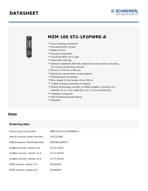
DATASHEETDataOrdering dataProduct type description MZM 100 ST2-1P2PWRE-A Article number (order number)101211066EAN (European Article Number)4030661389127eCl@ss number, version 9.027-27-26-03eCl@ss number, version 11.027-27-26-03eCl@ss number, version 12.027-27-26-03ETIM number, version 7.0EC002593ETIM number, version 6.0EC002593Approvals - StandardsCertificates TÜVcULusEACGeneral dataStandards EN 60947-5-3EN ISO 13849-1EN ISO 14119IEC 61508Coding Universal codingLowCoding level according to ISO14119Working principle inductiveEnclosure material Glass-fibre, reinforced thermoplastic Gross weight700 gTime to readiness, maximum4,000 msReaction time, maximum150 msDuration of risk, maximum150 msGeneral data - FeaturesPower to lock YesSolenoid interlock monitored YesLatching YesShort circuit detection YesCross-circuit detection YesSeries-wiring YesSafety functions YesIntegral system diagnostics, status YesNumber of safety contacts2Number of series-wiring of sensors31Safety classificationStandards EN ISO 13849-1IEC 61508Safety classification - Interlocking functionPerformance Level, up to eCategory4PFH value 3.54 x 10⁻⁹ /h3Safety Integrity Level (SIL),suitable for applications inMission time20 Year(s)Mechanical dataMechanical life, minimum1,000,000 OperationsNote (Mechanical life)Actuating speedOperations for door weights ≤ 5 kg Holding force, typically750 NHolding force, guaranteed500 NLatching force, minimum30 NLatching force, maximum100 NMechanical data - Connection techniqueType of connection Connector M12, 8-poleMechanical data - DimensionsLength of sensor40 mmWidth of sensor40 mmHeight of sensor179 mmAmbient conditionsDegree of protection IP65IP67Ambient temperature, minimum-25 °CAmbient temperature, maximum+55 °CStorage and transport-25 °Ctemperature, minimum+70 °CStorage and transporttemperature, maximumRelative humidity, minimum30 %Relative humidity, maximum95 %Note (Relative humidity)non-condensingnon-icingResistance to vibration to EN10 … 150 Hz, amplitude 0.35 mm 60068-2-6Restistance to shock30 g / 11 msProtection class IIIAmbient conditions - Insulation values32 VDCRated insulation voltage Ui0.8 kVRated impulse withstand voltage UimpOvervoltage category IIIDegree of pollution to VDE 01003Electrical dataOperating voltage, minimum20.4 VDCOperating voltage, maximum26.4 VDC600 mANo-load supply current, maximum IOperating current1,000 mA50 mARequired rated short-circuit100 Acurrent to EN 60947-5-1Note Cable length and cable section alter the voltage drop depending on the outputcurrentSwitching frequency, maximum 1 HzElectrical data - Magnet controlSwitching thresholds-3 V … 5 V (Low)15 V … 30 V (High)Classification ZVEI CB24I, Sink C0Classification ZVEI CB24I, Source C1C2C3Electrical data - Safety digital inputsSwitching thresholds−3 V … 5 V (Low)15 V … 30 V (High)Classification ZVEI CB24I, Sink C1Classification ZVEI CB24I, Source C1C2C3Electrical data - Safety digital outputsRated operating current (safety250 mAoutputs), maximum 1 VVoltage drop UdLeakage current I0.5 mArVoltage, Utilisation category DC-1324 VDCCurrent, Utilisation category DC-130.25 AClassification ZVEI CB24I, Source C1Classification ZVEI CB24I, Sink C1Electrical data - Diagnostic outputsVoltage drop Ud, maximum 2 V Voltage, Utilisation category DC-1324 VDC Current, Utilisation category DC-130.05 AStatus indicationNote (LED switching conditions display)Operating condition: LED green Error / functional defect: LED red Supply voltage UB: LED greenPin assignmentPIN 1A1 Supply voltage UBPIN 2X1 Safety input 1PIN 3A2 GNDPIN 4Y1 Safety output 1PIN 5OUT Diagnostic outputPIN 6X2 Safety input 2PIN 7Y2 Safety output 2PIN 8IN Solenoid controlScope of deliveryScope of delivery Actuators must be ordered separately.AccessoryRecommendation (actuator)MZM 100-B1.1NoteNote (General)As long as the actuating unit is applied to the solenoid interlock, the unlockedsafety guard can be relocked. In this case, the safety outputs are re-enabled, sothat the safety guard must not be opened.Ordering codeProduct type description:MZM 100(1)(2)(3)(4)(5)(1)without Solenoid interlock monitoredB Actuator monitored(2)ST2Connector plug M12, 8-poleST Connector plug M23, 8+1-pole(3)1P2P 1 p-type diagnostic output and 2 p-type safety outputs(only in connection with "Solenoid interlock monitored") 1P2PW serial diagnostic output and 2 p-type safety outputs(4)without electrically adjustable latching force 30 … 100 N(5)PicturesProduct picture (catalogue individual photo)dpi| 22.1 kB | .png | 74.083 x 100.189 mm - 210 x 284 px - 72 dpiDimensional drawing basic component| 20.7 kB | .swf || 5.2 kB | .png | 74.083 x 50.8 mm - 210 x 144 px - 72 dpi| 160.8 kB | .jpg | 352.778 x 242.358 mm - 1000 x 687 px - 72dpiDimensional drawing miscellaneous| 12.9 kB | .swf || 290.8 kB | .jpg | 352.425 x 362.656 mm - 999 x 1028 px - 72dpiWiring example| 37.0 kB | .cdr || 86.9 kB | .jpg | 352.778 x 161.572 mm - 1000 x 458 px - 72 dpiContact arrangement| 139.8 kB | .jpg | 352.778 x 380.647 mm - 1000 x 1079 px - 72dpiSchmersal, Inc., 15 Skyline Drive, Hawthorne, NY 10532The details and data referred to have been carefully checked. Images may diverge from original. Further technical data can be found in the manual. Technical amendments and errors possible.Generated on: 6/28/2022, 2:44 AM。
伊顿电动机断路保护器
电动机保护断路器PKZ
1.1 xStart系列电动机保护断路器
1
电动机保护断路器PKZ . . . . . . . . . . . . . . . . . . . . . . . . . . . . . . . . . . . . . . . . . . . . . . . . . . . . 3
PKE电子式电动机保护断路器 . . . . . . . . . . . . . . . . . . . . . . . . 8
标准辅助触点 . . . . . . . . . . . . . . . . . . . . . . . . . . . . . . . . . . . . 10
辅助触点、分励脱扣器、欠压脱扣器 . . . . . . . . . . . . . . . . . . 12
P
P
kW kW
440 V
P kW
500 V 660 V 690 V
P
P
kW kW
额定 持续 电流
Iu A
电动机保护断路器,“1”类和“2”类配合
–
–
–
–
0.06 0.16
–
0.06 0.06 0.06 0.12 0.25
0.06 0.09 0.12 0.12 0.18 0.4
0.09 0.12 0.18 0.25 0.25 0.63
2.5…4
56
4…6.3
88
6.3…10 140
8…12
168
10…16
224
16…20
280
20…25
350
25…32
448
10…16
224
16…25
高性能热电阻断路器4140说明书
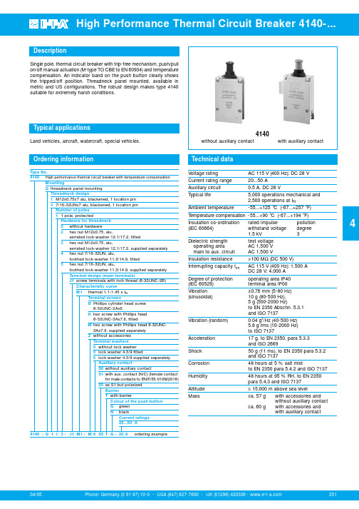
Phone: Germany (0 91 87) 10-0 - USA (847) 827-7600 - UK (01296) 420336 - 04/052514DescriptionTypical applicationsTechnical dataSingle pole, thermal circuit breaker with trip-free mechanism, push/pull on/off manual actuation (M-type TO CBE to EN 60934) and temperature compensation. An indicator band on the push button clearly shows the tripped/off position. Threadneck panel mounted, available in metric and US configurations. The robust design makes type 4140suitable for extremely harsh conditions.Land vehicles, aircraft, watercraft, special vehicles.4140without auxiliary contact with auxiliary contactVoltage ratingAC 115 V (400 Hz); DC 28 V Current rating range 20...50 AAuxiliary circuit 0.5 A, DC 28 VTypical life5,000 operations mechanical and 2,500 operations at I NAmbient temperature -55...+125 °C (-67...+257°F) T emperature compensation -55...+90 °C (-67...+194 °F)Insulation co-ordination rated impulse pollution (IEC 60664) withstand voltage degree1.5 kV 3Dielectric strength test voltage operating area AC 1,500 V main to aux. circuit AC 1,500 V Insulation resistance >100 M Ω(DC 500 V)Interrupting capacity I cnAC 115 V (400 Hz): 1,500 A DC 28 V: 4,000 ADegree of protection operating area IP40 (IEC 60529)terminal area IP00Vibration ±0.76 mm (5-80 Hz) (sinusoidal) 10 g (80-500 Hz),5 g (500-2000 Hz)to EN 2350 Abschn. 5.3.1and ISO 7137Vibration (random) 0.04 g 2/Hz (40-500 Hz)5.8 g rms (10-2000 Hz)to ISO 7137Acceleration 17 g, to EN 2350, para 5.3.3and ISO 2669Shock 50 g (11 ms), to EN 2350 para 5.3.2and ISO 7137Corrosion 48 hours at 5 % salt mistto EN 2350 para 5.4.2 and ISO 7137Humidity 48 hours at 95 % RH, to EN 2350para 5.4.3 and ISO 7137Altitude ≤15,000 m above sea level Massca. 57 gwith accessories andwithout auxiliary contactca. 60 g with accessories andwith auxiliary contactOrdering informationType No.4140High performance thermal circuit breaker with temperature compensationMountingG threadneck panel mounting Threadneck design1M12x0.75x7 alu, blackened, 1 location pin 37/16-32UNx7 alu, blackened, 1 location pin Number of poles 1 1 pole, protectedHardware for threadneck 0without hardware2hex nut M12x0.75, alu,serrated lock-washer 12.1/17.2, fitted 3hex nut M12x0.75, alu,serrated lock-washer 12.1/17.2, supplied separately 4hex nut 7/16-32UN, alu,toothed lock-washer 11.3/14.9, fitted 5hex nut 7/16-32UN, alu,toothed lock-washer 11.3/14.9, supplied separately Terminal design (main terminals)J1screw terminals with inch thread (8-32UNC-2B)Characteristic curveM1thermal 1.1-1.45 x I NTerminal screwsB Phillips cylinder head screw 8-32UNC-2Ax6K hex screw with Phillips head 8-32UNC-3Ax7.6, fittedM hex screw with Phillips head 8-32UNC-3Ax7.6, supplied separately Z without accessories Terminal washers 0without lock washer 5lock washer 4.3/9 fitted6lock washer 4.3/9 supplied separately Auxiliary contactS0without auxiliary contactS1with aux. contact (N/C) (female contactfor male contacts to EN3155-016M2018)S5as S1 but polarizedBarrierT with barrierColour of the push button G green N blackCurrent ratings 20...50 A 4140 -G 11 3 -J1 M1 -M 6S5T G -20 Aordering example。
负压隔离器说明
dzprc
16 17 18 19 20 21 22 23 24
25 26 27 28 29 30
31
排水球阀 触摸屏 电器柜 变频器 CPU 模块 安装导轨 电源模块 PLC 接线端子 MMC 存储卡 防安全门锁 急停开关 电磁阀 防爆灯具 插座 手动蝶阀 αβ阀
316L 不锈钢,1.5” 套
苏州东中机械设备有限公司
2015-12-21
第 12 页
PQ 确认的目的:在安装确认和运行确认的基础上,根据使用厂家的具体生产工艺加入 相应的试验品进行试验,确认设备的运行性能符合设计要求,并符合新版 GMP 的相关要求 详细文本资料在做现场验证时提供
7.售后服务
第 11 页
dzprc
保修内容:设备质保期为1年,自设备安装调试验收合格之日起计算,质保期内公司提 供免费维修服务。 (1) 在质保期内的保修内容
不锈钢桶
过滤器及其它
压差表 压差变送器 手套 喷枪 喷枪快速接头 氧含量传感器 手套圈 氮气流量计 氮气球阀
过滤效率 99.993
个
过滤效率 H13
套
SMC 气管接头;PU 管
路;pull 仪表、初效 套
过滤器等
0~250Pa/500Pa
个
0‐250PA
个
8Y15 32A
支
枪 1 把;气枪 1 把 把
1) 公司按照双方签订的合同内容提供设备的安装、调试,验证合格后,提供现场操作 及维修、管理人员的培训;培训的具体时间、地点、人数由用户公司协商安排。
2) 质保期内技术人员将会跟踪设备的运行情况,如产品运行不正常,用户就产品问题 向公司技术部门咨询,判定是否属于质量问题。用户可以通过售后电话咨询有关技 术问题,并得到明确的解决方案。若在电话中不能解决的问题,我司将在1小时内 响应用户的服务需求,并在48小时内到现场。
光伏连接器知识

光伏连接器知识1.连接器类型光伏连接器主要分为MC4、MC3、T型、J型、C型、E型、M型等类型。
其中,MC4型连接器由于其高可靠性、高防水性及易于安装等优点,在光伏系统中得到了广泛应用。
2.连接器材质光伏连接器的材质主要分为铜和铝两种。
铜质连接器具有更好的导电性能和机械强度,而铝质连接器则更轻便且成本更低。
选择哪种材质的连接器应根据具体的应用场景和需求进行决定。
3.连接器规格光伏连接器的规格主要根据其额定电流和电压进行划分。
不同的规格适用于不同的光伏系统,选择合适的规格可以确保连接器的可靠性和安全性。
4.连接器使用注意事项在使用光伏连接器时,应注意以下几点:a.确保连接器接触良好,避免松动或接触不良导致发热或烧毁;b.避免在恶劣的环境条件下使用连接器,如高温、潮湿、腐蚀等;c.在安装和拆卸连接器时,应使用合适的工具,避免损坏连接器或电缆;d.在使用过程中,应定期检查连接器的状态,确保其正常工作。
5.连接器维护与保养对于光伏连接器的维护与保养,应定期进行以下操作:a.清洁连接器表面,去除灰尘和污垢;b.检查连接器的紧固件是否松动,如有需要,进行紧固;c.对于损坏或老化的连接器,应及时更换。
6.连接器常见问题及解决方案光伏连接器在使用过程中可能会出现以下问题:a.接触不良:可能是由于接触点氧化或污垢导致。
解决方案为清洁接触点并确保其接触良好;b.松动或脱落:可能是由于紧固件松动或老化导致。
解决方案为检查并紧固所有紧固件;c.过热:可能是由于电流过大或接触不良导致。
解决方案为检查并调整电流或更换接触点更好的连接器;d.损坏:可能是由于过载、短路或外部因素导致。
解决方案为更换损坏的连接器并检查其他可能的故障原因。
7.连接器选型指南在选择光伏连接器时,需要考虑以下因素:a.电流和电压要求:根据光伏系统的需求选择合适的额定电流和电压;b.环境条件:考虑工作环境中的温度、湿度、腐蚀等因素,选择适应的材质和防护等级;c.成本:在满足性能要求的前提下,选择性价比高的产品;d.易于安装和维护:选择易于安装和维护的连接器类型和规格。
Agilent SPME Fiber or Arrow Manual Injection Kit U

12345SPME Fiber or Arrow Manual Injection KitSPME manual samplingThe Agilent manual injection kit will allow the end user to extract samples using SPME fibers or Arrows. They can then inject the samples into a GC inlet.Manual SPME SamplingSPME fibers and Arrowsp/n 5191-58772PAL3 alignment ring (gray) for split/splitless (S/SL) inletManual injectionManual injection guidePAL3 alignment ring (Gray) for S/SL inlet (G7371-67001)The manual injection guide sits on thealignment ring for manual sample injection.3Methodology—manual samplingInstalling a PDMS SPME (100 μm) Arrow into the manual syringeLoosen the cap at the base of the syringe and remove it.Depress the black plunger completely.Screw the hub of an SPME fiber/Arrow into the bottom of the plunger at the end of thesyringe bodyRetract the black plunger and slide the cap over the SPME fiber/Arrow and tighten itonto the syringe.4The extraction guide has two positions where the syringe can be installed.The upper position is used for headspace extraction.The lower position is used for immersion extraction.Incorrect and correct position of the lower locking screw.Do not tighten the screw against the black plunger or you will not be able to move the SPME fiber/Arrow intoposition for sampling.Setting the locking screwsLarge inner diameter (id) locking screwSmall inner diameter (id) locking screwSlide the locking screws onto the syringe from the plunger side (the right side as shown above).• Install the large id locking screw onto the silver body of the syringe.• Install the small id locking screw onto the wider portion of the black plunger.•Tighten the locking screws until finger-tight. Do not overtighten, as they will be adjusted in later steps.5• Raise the syringe plunger to the fully extended position and insert the syringe and lower locking screw into the upper position of the extraction guide.•Lock the syringe into place by rotating it until the locking screw is positioned in the notch.• Adjust the syringe so that the SPME fiber/Arrow is protruding ~1 cm beyond the inner base of the extraction guide (A).• Tighten the lower locking screw securely.•The tip of the SPME fiber/Arrow will be recessed at least 1 mm in from the end ofthe extraction guide (B).A BSetting the locking screws for septum penetration depthPlace the extraction guide (with syringe in place) on a headspace sampling vial and loosen the upper locking screw.Adjust the SPME fiber/Arrow to the desired exposure depth by moving the black plunger.Choose a depth that ensures that the SPME fiber/Arrow will be in the gas phase.Once the SPME fiber/Arrow is at the proper depth, hold the plunger in place and slide the upper locking screw until it is flush against the top of the silver syringe body. Then tighten the upper locking screw securely.Setting the exposure depth for headspace extraction6Fine depth adjustment for direct immersion extractionAdjusting the injector penetration depthInsert the syringe into the lower position of the extraction guide.1. Manual SPME injection guide2. PAL3 alignment ring (gray) forS/SL inlet (G7371-67001)• Carefully insert the syringe into the injection guide.• Use caution to avoid damaging the SPME fiber/Arrow when threading it through the hole in the base of the injection guide.•Lock the syringe into place by rotating it until the locking screw is positioned in the notch.Penetrate a vial and fully expose the SPME fiber/Arrow within the vial.Adjust the lower locking screw and upper locking screw to obtain the desired exposure depth (to ensureimmersion in the sample liquid).127Setting injector penetration depthWith the appropriate GC-specific adaptor cup on the end of the injection guide, measure the distance from the tip of the SPME fiber/Arrow to the groove inside the adaptor cup.Adjust the desorption depth by screwing the body of the injection guide up or down (maximum depth = 67 mm).Twist the locking ring down until it locks on the body of the injection guide./chemDE.3985648148This information is subject to change without notice.© Agilent Technologies, Inc. 2020 Printed in the USA, March 6, 2020 5994-1732ENInjection onto the GC inletRemove the adapter cup from the injection guide.The adapter cup is placed onto the GC inlet to guide the manual injection.Push the plunger down until the top locking screw is resting on the body of the syringe.The sample is then injected.。
美国Eaton公司产品Eaton Moeller系列SVB安卓铜锁定功能说明书
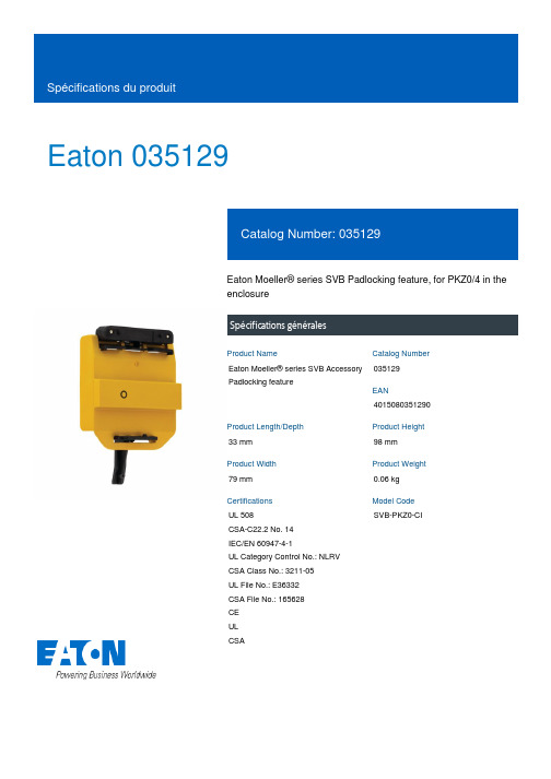
Eaton 035129Eaton Moeller® series SVB Padlocking feature, for PKZ0/4 in theenclosureSpécifications généralesEaton Moeller® series SVB AccessoryPadlocking feature035129401508035129033 mm98 mm79 mm0.06 kgUL 508CSA-C22.2 No. 14IEC/EN 60947-4-1UL Category Control No.: NLRV CSA Class No.: 3211-05UL File No.: E36332CSA File No.: 165628CEULCSA SVB-PKZ0-CIProduct Name Catalog NumberEANProduct Length/Depth Product Height Product Width Product Weight Certifications Model CodeLockable in the 0 (Off) position Polycarbonate AccessoriesMain switch to IEC/EN 60204-25 °C 55 °C 0 W0 W0 W0 A0 WMeets the product standard's requirements.Meets the product standard's requirements.Meets the product standard's requirements.Meets the product standard's requirements.Please enquireDoes not apply, since the entire switchgear needs to be evaluated.Does not apply, since the entire switchgear needs to be evaluated.Meets the product standard's requirements.Locking facility Material Product Category Suitable asAmbient operating temperature - min Ambient operating temperature - max Equipment heat dissipation, current-dependent PvidHeat dissipation capacity PdissHeat dissipation per pole, current-dependent PvidRated operational current for specified heat dissipation (In) Static heat dissipation, non-current-dependent Pvs10.2.2 Corrosion resistance10.2.3.1 Verification of thermal stability of enclosures10.2.3.2 Verification of resistance of insulating materials to normal heat10.2.3.3 Resist. of insul. mat. to abnormal heat/fire by internal elect. effects10.2.4 Resistance to ultra-violet (UV) radiation10.2.5 Lifting10.2.6 Mechanical impact10.2.7 InscriptionsDoes not apply, since the entire switchgear needs to be evaluated.Meets the product standard's requirements.Does not apply, since the entire switchgear needs to be evaluated.Does not apply, since the entire switchgear needs to be evaluated.Is the panel builder's responsibility.Is the panel builder's responsibility.Is the panel builder's responsibility.Is the panel builder's responsibility.Is the panel builder's responsibility.Not applicable.Is the panel builder's responsibility. The specifications for the switchgear must be observed.Is the panel builder's responsibility. The specifications for the switchgear must be observed.The device meets the requirements, provided the information in the instruction leaflet (IL) is observed.DA-CE-ETN.SVB-PKZ0-CIIL03402031Zeaton-manual-motor-starters-enclosure-ci-k-accessory-dimensions-002.epseaton-manual-motor-starters-padlock-svb-padlocking-feature-3d-drawing.epseaton-manual-motor-starters-transformer-pkzm0-wiring-diagram.eps10.3 Degree of protection of assemblies10.4 Clearances and creepage distances10.5 Protection against electric shock10.6 Incorporation of switching devices and components 10.7 Internal electrical circuits and connections10.8 Connections for external conductors10.9.2 Power-frequency electric strength10.9.3 Impulse withstand voltage10.9.4 Testing of enclosures made of insulating material 10.10 Temperature rise10.11 Short-circuit rating10.12 Electromagnetic compatibility10.13 Mechanical function eCAD model Instructions d'installation SchémasSchémas électriquesEaton Corporation plc Eaton House30 Pembroke Road Dublin 4, Ireland © 2023 Eaton. Tous droits réservés. Eaton is a registered trademark.All other trademarks areproperty of their respectiveowners./socialmedia。
AMP Mini CT 连接器系列说明书
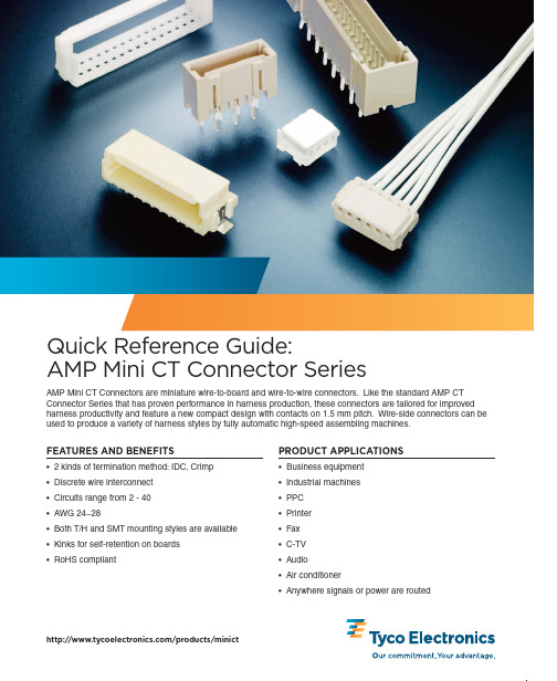
2AMP Mini CT Connector SeriesDUAL ROW ASSEMBLIESPHOTO KEY/products/minictAll part numbers are RoHS compliant.Requires a holder to be used along with a single row housing.Photos correspond to part numbers on page 3.Shows an unstripped wire inserted into an MT Housing.Shows a contact crimped onto a stripped wire to be inserted into a crimp housing.MT Mini CT ConnectorCrimp Mini CT ConnectorCrimp Mini CT Contact MASS TERMINATION (MT) VS. CRIMP POKEMTCrimp Poke Time savingsCost effective Preloaded IDC contacts Flexibility (AWG)AutomationManual laborMates w/ same headers as Crimp Mates w/ same headers as MT35392335390835390763.67.47.47.4688Receptacle Connector (single)Single Row HousingDual Row HousingHolderPost HeaderBoss663.63.6AMP Mini CT HousingAMP Mini CT HousingAMP Mini CT ContactAMP Mini CT HeaderAMP Mini CT HolderAMP Mini CT HeaderAMP Mini CT HeaderAMP Mini CT HeaderAMP Mini CT HeaderAMP Mini CT Panel MountPhoto APhoto EPhoto IPhoto JPhoto FPhoto GPhoto HPhoto BPhoto CPhoto DAMP Mini CT Connector Series3PCB CONNECTORSCABLE SIDE CONNECTORSHOW TO SELECT AN AMP MINI CT CONNECTOR PART NUMBERMT CONNECTORSCrimp Type Connectors/products/minictAll part numbers are RoHS compliant.CONTACTS SINGLE ROW POST HEADER ASSEMBLIES BOARD-MOUNT SINGLE ROW POST HEADER ASSEMBLIES PANEL-MOUNT DUAL ROW HEADERS DUAL ROW POST HEADER ASSEMBLIES - BOARD-MOUNT DUAL ROW POST HEADER ASSEMBLIES - PANEL-MOUNT RATINGSRECEPTACLE CONNECTORS (WIRE APPLICATION)CRIMP TYPE HOUSING Mating Part Numbers: 292206; 292207; 292227; 292228; 292239; 292231; 292215; 292208; 292216Specifications : BMating Part Numbers: (MT) 353293 or (Crimp) 353908 w/ 353907-1 or 353918-1Specifications : A, X353294 w/ 2 x MT or 2 x Crimp Single Row HeadersSpecifications : A, C, X353294 w/ 2 x MT or 2 x Crimp Single Row HeadersSpecifications : C, XMating Part Numbers: 2 x (MT) 353293 or 2 x (Crimp) 353908 w/ 353907-1 or 353918-1Specifications : C, XSpecifications : A, XPart Number Receptacle Contact Specifications 353907-1Reel - AWG: 26-28B, Y 353918-1Loose Piece - AWG 24-28 (See Photo B on page 2)B, YVoltageCurrent (Amps)TemperatureProduct Specifications AWG 2224262830A 108-6001850 V (AC/DC)AMPS 21-30 to 105°CB 108-6002550 V (AC/DC)AMPS 22-30 to 105°C C 108-5225250 V ACAMPS 33221-65 to 105°CMating Part Numbers: (MT) 353293 or (Crimp) 353908 w/ 353907-1 or 353918-1Specifications: A, XApplication Specifications X 114-5223Y 114-5245The charts on this page highlight the relationship between the number of contacts (positions) to the part number. Please see the sample chart below that was designed to help you select the correct part number for your needs. For single digit position to dash numbers, attach the digit to the end of the base number. For double digit position to dash numbers, attach the first digit to the front of the part number, add a dash and the base part number, then follow the base part number with a dash and the second digit.© 2009 Tyco Electronics Corporation. All Rights Reserved.AMP , DECAM, TE LOGO and TYCO ELECTRONICS are trademarks. Other products, logos and company names mentioned herein may be trademarks of their respective owners.Dimensions are in millimeters with inches (if shown) in brackets. Specifications subject to change.For more information, contact your Tyco Electronics sales engineer at the numbers listed below, or visit our Website at: . USA: 1-800-522-6752S. America: 55-11-2103-6000 France: 33-1-3420-8686Canada: 1-905-470-4425Germany: 49-6251-133-1999 Netherlands: 31-73-6246-999Mexico & C. America: 52-55-1106-0814UK: 31-73-6246-431 China: 86-400-820-60156-1773454-5–1K–CIS–AH–04/09DisclaimerWhile Tyco Electronics has made every reasonable effort to ensure the accuracy of the information in this catalog,Tyco Electronics does not guarantee that it is error-free, nor does Tyco Electronics make any other representation,warranty or guarantee that the information is accurate, correct, reliable or current.Tyco Electronics reserves the right to make any adjustments to the information contained herein at any time without notice. Tyco Electronics expressly disclaims all implied warranties regarding the information contained herein,including, but not limited to, any implied warranties of merchantability or fitness for a particular purpose. The dimensions in this catalog are for referencepurposes only and are subject to change without notice.Specifications are subject to change without notice. Please consult Tyco Electronics for the latest dimensions and design specifications.Restriction on the use of Hazardous Substances (RoHS)At Tyco Electronics, we’re ready to support your RoHS requirements. We’ve assessed more than 1.5 million end items/components for RoHS compliance, and issued new part numbers where any change was required to eliminate the restricted materials. Part numbers in this catalog are identified as:RoHS Compliant — Part numbers in this catalog are RoHS Compliant, unless marked otherwise. These products comply with European Union Directive 2002/95/EC as amended 1 January 2006 that restricts the use of lead, mercury, cadmium, hexavalent chromium, PBB, and PBDE in certain electrical and electronic products sold into the EU as of 1 July 2006.NOTE:For purposes of this Catalog, included within the definition of RoHS Compliant are products that are clearly “Out of Scope” of the RoHS Directive such as hand tools and other non-electrical accessories.NOTE:Information regarding RoHS compliance is provided based on reasonable inquiry of our suppliers and represents our current actual knowledge based on the information provided by our suppliers. This information is subject to change. For latest compliance status, refer to our website referenced at right.Getting the Information You NeedOur comprehensive on-line RoHS Customer Support Center provides a forum to answer your questions and support your RoHS needs. A RoHS FAQ (Frequently Asked Questions) is available with links to more detailed information. You can also submit RoHS questions and receive a response within 24 hours during a normal work week. The Support Center also provides:Cross-Reference from Non-compliant to Compliant ProductsAbility to browse RoHS Compliant Products in our on-line catalogDownloadable Technical Data CustomerInformation Presentation More detailed information regarding the definitions used aboveSo whatever your questions when it comes to RoHS, we’ve got the answers at /leadfreeRoHSCustomer Support CenterQUESTIONS TO ASK AT DESIGN IN•What wire gauge will you be using?More flexibility with AWG when using Crimp (24~28 AWG) vs.MT (26~28 AWG).•Are the connectors available for IDC?Yes, we offer an MT version that is preloaded with IDC contacts.•Is your process automated?MT housings are suitable for automated processes.•What current, voltage and operating temperature is required?Please see product specification information on the charts on page 3 of this document.•Which is a more standard header, with or without a locating boss?The most standard headers tend to have a locating boss as it makes it easier for the customer to align the connector onto their board.•What special retention mechanisms are available to provide stability?Tyco Electronic's T/H headers have a staggered tine design to provide stability.•What are my tooling options?Tyco Electronics offers comprehensive tooling optionsincluding manual pistol-grips, manual mini-press, pneumatic mini-press, semi-auto DECAM and an automatic DECAM tool.For more information, please visit .YOU ARE HERE (E-CATALOG)Product Overview Page/products/minict Breakdown From Main PageAMP Mini CT Connector Series。
固定座隔离柱规格
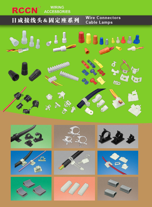
六角内螺纹隔离柱六角内螺纹隔离柱日成接线头&固定座系列Wire ConnectorsCable Lamps六角内螺纹隔离柱六角内螺纹隔离柱日成保护部品&扣具系列Bushings&Fasteners接线组:12对/条 可定制其它孔数Terminal blocks:12 pcs/barKW-1KW-3KW-2KW-10KW-12KW-11KW-5KW-4KW-6KW-6L接线组:12对/条 可定制其它孔数Terminal blocks :12 pcs/barHMPHC-4PHC-1509PHC-8PHC-6.5PHC-5PHC-5B3M背胶GM TYPEGM-0603 GMC TYPEKG开孔式KGS Opening type 密封式Closed typeKGS直切式KGS Cutting in barED密封式ED Closed type梯形结构梯形结构直形结构推荐Straight constructionTerraced constructionTerraced construction适用电线尺寸铁板孔径MountingHole 线扣长度PartL.材 质:UL合格之NYLON66(黑色),防火等级94V-2使用方法:按上序3图装配即可。
RH-648RH-667RH-496RH-51RH-5RH-6RH-487RH-497RH-498RH-53RH-59RH-50RH-488RH-502RH-549脚部可开式RH-54RH-52开后效果RCCN日成KWSN型马鞍型夹线套 KWS-1110KWS-1308KWS-1106KWS-1310KWS-2314RCCN 日成SP型隔离柱 。
各国插头标准汇总
各国插头标准汇总--1 主要国家 ( 地域 ) 的电源电压和电源线插头形式主要国家(地域)的电源电压和电源线插头形式是在Q/FSX 10235的基础上加以增补见附录A,依据入口国或合同要求在详细产品标准中规定。
2 主要国家 ( 地域 ) 的电源线插头图形2.1主要国家 ( 地域 ) 的电源线插头图形见附录B,依据入口国或合同要求选择使用。
2.2各个国家 ( 地域 ) 的标准对电源线插头的绝缘尺寸有相应的要求,但对外形和颜色没有强迫要求,不一样的生产厂家其产品外形可能有所不一样,插头的颜色可依据客户的要求进行选择,故附录 B 中的电源线插头图形不是独一的选择。
2.3选择电源线插头时,要考虑到入口国对电源线插头获得市场准入认证的要求。
2.4电源线插头合用设施种类a)Ⅱ类设施:是指其防触电不单依赖基本绝缘并且采纳诸如两重绝缘或增强绝缘之类的附带安全举措的设施,俗称非接地设施。
b)Ⅰ类设施:是指其防触电不单依赖基本绝缘并且采纳附带安全举措的设施,俗称接地设施。
---主要国家 ( 地域 ) 的电源电压和电源线插头型式表 A.1主要国家 ( 地域 ) 的电源电压和电源线插头型式AC Supply Colour BroadcastingCertificatioCountry/Area System Stereo Subtitles Channel System Plug TypeSystem nVoltage Frequency VHF UHFAfghanistan( 阿富汗 )220V50Hz PAL B D W.European A见图 14、15、16、17Albania(阿尔巴尼亚 )220v50Hz PAL B G W.European A见图 14、15、16、17Algeria(阿尔及利亚 )220V50Hz PAL B W.European A见图 14、15、16、17Angola( 安哥拉 )220V50Hz PAL I A见图 14、15、16、17Argentina( 阿根廷 )220V50Hz PAL N American G见图 1、2Australia(澳大利亚 )240V50Hz PAL B FM-FM Teletext Australian F见图 3、4Austria(奥地利 )230V50Hz PAL B G FM-FM Teletext W.European A见图 14、15、16、17Antigua & Barbuda(安提瓜和巴布达 )120V60Hz NTSC M American C见图 52Bahamas(巴哈马 )120/240V60Hz NTSC M American C见图 52Bahrain(巴林 )230V50Hz PAL B G W.European A见图 14、15、16、17Bangladesh( 孟加拉 )220V50Hz PAL B W.European A见图 14、15、16、17Andorra(安道尔 )220v50Hz NTSC M A见图 14、15、16、17Belgium( 比利时 )230V50Hz PAL B G NICAM Teletext W.European A见图 14、15、16、17Belize( 伯利兹 )120V60Hz NTSC M American C、E见图 52Benin( 贝宁 )220V50Hz SECAM K1A见图 14、15、16、17Bhutan( 不丹 )220V50Hz PAL B A、H见图 14、15、 16、17、49、50、 51 Bolivia(玻利维亚 )110/220V50Hz NTSC M American A、C见图 52、14、15、16、17Bosnia/Hercegovina(波斯尼亚 / 塞尔维亚 - 克罗地亚 )220V50Hz PAL B G W.European A见图 14、15、16、17---表A.1续AC Supply Colour BroadcastingCountry/Area SystSystemVoltage Frequency VHF UHF Botswana( 博茨瓦纳 )220V50Hz SECAM K1Brazil(巴西 )127/220V60Hz PAL M M Brunei(文莱 )230V50Hz PAL BBulgaria(保加利亚 )220V50Hz SECAM D K Burkina Faso(布基纳法索 )220V50Hz SECAM K1Burundi(布隆迪 )220V50Hz SECAM K1Cameroon(喀麦隆 )220V50Hz PAL BCanada( 加拿大 )120V60Hz NTSC M M Canary Islands(加那利群岛 )127/220V50Hz PAL B G Cape Verde(Cape 佛得角 )220V50Hz PAL B G Chad( 乍得 )220V50Hz SECAM DChile( 智利 )220V50Hz NTSC MCook islands(科克群岛 )220V50Hz PAL BChina( 中国 )220V50Hz PAL DColombia( 哥伦比亚 )120V60Hz NTSC M M Comoros( 科摩罗 )220V50Hz SECAM K1Congo( 刚果 )220V50Hz PAL DCosta Rica( 哥斯达黎加 )110V60Hz NTSC M M Cote d' Ivoire220V50Hz SECAM K1Croatia(克罗地亚 )220V50Hz PAL B G Cuba( 古巴 )110V60Hz NTSC MCyprus( 塞浦路斯 )240V50Hz PAL B G Czech( 捷克 )220V50Hz PAL B/D G/KStereo Subtitles Channel System Certification Plug TypeH见图 13、43、49、50、51MTS CC American A、 E见图 5、6、 7、 8、9、52W.European A见图 14、15、16、17E.European A见图 14、15、16、17A见图 14、15、16、17A见图 14、15、16、17A见图 14、15、16、17American C见图 52、53、54W.European A见图 14、15、16、17、27、28A见图 14、15、16、17A见图 14、15、16、17、43American A见图 14、15、16、17、27、28、29、30F、 D见图 3、4、 10、 11、 12Chinese D见图 10、11、12American C、 E见图 52、53、54A见图 14、15、16、17A见图 14、15、16、17、43American C、 E见图 52、53、54A见图 14、15、16、17E.European A见图 14、15、16、17American A、 C、E、见图 14、15、16、 17、 52 、 53、54W.European H见图 13、49、50、51W.European A见图 14、15、16、17-----Denmark( 丹麦 )230V50Hz PAL B G NICAM Teletext W.European A见图14、15、16、17表 A.1AC Supply Colour BroadcastingCountry/Area SystemSystemVoltage Frequency VHF UHF Djibouti(吉布提 )220V50Hz SECAM K1Dominican(rep)(多米尼加共和国 )110/220V60Hz NTSC MEcuador( 厄瓜多尔 )110V60Hz NTSC MEgypt( 埃及 )220V50Hz SECAM/PALB GEl Salvador( 萨尔瓦多 )110V60Hz NTSC M M Equatorial Guinea(赤道几内亚 )220V50Hz SECAM BEstonia(爱沙尼亚 )220V50Hz SECAM D K Ethiopia(埃俄比亚 )127/220V50Hz PAL B GFiji( 斐济 )240V50Hz PAL BFinland(芬兰 )230V50Hz PAL B G France( 法国 )230V50Hz SECAM L L French guiana( 法属圭亚那 )120/220V50Hz SECAM K1Gambia( 冈比亚 )230V50Hz PAL BGabon(加蓬 )220V50Hz SECAM K1Germany(德国 )230V50Hz PAL B G Ghana(加纳 )240V50Hz PAL BGreece( 希腊 )230V50Hz PAL B G Guam(关岛 )120V60Hz NTSC MGreenland( 格陵兰 )220V50Hz PAL BGrenada( 格林纳达 )220V50Hz NTSC MGuatemala( 危地马拉 )120V60Hz NTSC MGuinea( 几内亚 )220V50Hz PAL K1续Stereo Subtitles Channel System Certification Plug TypeA见图 14、15、16、17American C见图 52 、53、54American C、E见图 52 、53、54W.European A见图 14、15、16、17American C、E见图 52 、53、54A见图 14、15、16、17E.European A见图 14、15、16、17H、ITALY见图 43 、44、45、46、27、28、29、30A见图 1、3、 4、 10、 11、 12NICAM Teletext W.European A见图 14、15、16、17Antiope French A见图 14、15、16、17A见图 14、15、16、17、43H见图 13、49、50、51A见图 14、15、16、17IGR/A2W.European A见图 14、15、16、17W.European H见图 13、49、50、51W.European A见图 14、15、16、17American C见图 52 、53、54W.European A见图 14 、13American H见图 13、49、50、51American C、E见图 52、53、54、1、3、 4、 10A见图 13、14、15、16、17-----Guinea Bissau( 几内亚比绍 )220V50Hz PAL I A见图 14、15、16、17 Guyana( 圭亚那 )110/220V50/60Hz NTSC M American C、E见图 52、53、54表 A.1AC Supply Colour BroadcastingCountry/Area SystemVoltage Frequency System VHF UHF Haiti(海地 )110/220V60Hz NTSC MHonduras( 洪都拉斯 )110V60Hz NTSC MHong Kong( 香港 )220V50Hz PAL IHungary( 匈牙利 )220V50Hz PAL D K Iceland( 冰岛 )230V50Hz PAL B G India(印度 )240V50Hz PAL BIndonesia(印尼 )110/240V50Hz PAL BIran(伊朗 )220V50Hz SECAM BIraq(伊拉克共和国 )220V50Hz SECAM BIreland(爱尔兰 )230V50Hz PAL I Israel(以色列 )230V50Hz PAL B GItaly(意大利 )220V50Hz PAL B G Jamaica( 牙买加 )110/220V60Hz NTSC MJapan( 日本 )100V50/60Hz NTSC MJordan( 约旦 )220V50Hz PAL B G Kenya( 肯尼亚 )240V50Hz PAL BKiribati(基里巴斯 )240V50HzKorea(N) (朝鲜 )220V60Hz SECAM/PALD K Korea(S)(韩国 )110/220V60Hz NTSC MKuwait( 科威特 )240V50Hz PAL B G Laos( 老挝 )220V50Hz PAL M---续Stereo Subtitles Channel System Certification Plug TypeAmerican C见图 52、53、54American C见图 52、53、54NICAM British H见图 18E.European A见图 14、15、16、17W.European A见图 14、15、16、17W.European A见图 19、20、21W.European A见图 22、23、24、25、26W.European A见图 14、15、16、17W.European A、 H见图 13、14、15、16、17、49、50、51NICAM Teletext Irish A、 H见图 13、14、15、16、17、49、50、51W.European A见图 14、15、16、17、27、28 FM/FM Teletext Italian A见图 27、28、29、30American C见图 52、53、54Japanese E见图 52、53、54W.European A、 H见图 13、14、15、16、17、49、50、51W.European A见图 14、15、16、17F见图 3、4E.European A见图 14、15、16、17American B见图 34、35、36W.European A见图 14、49、50、51American A见图 52、53、54Latvia( 拉脱维亚 )220V50Hz SECAM D K E.European A见图 14、15、16、17 Lebanon( 黎巴嫩 )110/220V50Hz PAL B G W.European A见图 52、14、、43、50表 A.1续AC Supply Colour BroadcastingCountry/Area System Stereo Subtitles Channel System Certification Plug TypeSystemVoltage Frequency VHF UHFLesotho(莱索托 )230V50Hz PAL I South African F见图 1、2、 3、 4Liberia(利比里亚 )120V60Hz PAL B W.European E见图 52、53、54Libya( 利比亚 )127/230V50Hz SECAM B W.European H见图 43Luxemburg( 卢森堡 )110/230V50Hz PAL/SECAM PAL-B SECAM-L Teletext W.European A见图 14、15、16、17 Madagascar( 马达加斯加 )110/220V50Hz SECAM K1A见图 14、43、44、45、46 Macedonia( 马其顿 )220V50Hz PAL B G W.European A见图 14、15、16、17Malawi( 马拉维 )230V50Hz PAL B G H见图 14、49、50、51 Malaysia(马来群岛 )240V50Hz PAL B W.European A见图 14、49、50、51Mali( 马里 )220V50Hz SECAM K1A见图 14、15、16、17Malta( 马耳他 )240V50Hz PAL B W.European H见图 13、49、50、51 Mauritania( 毛利塔尼亚 )220V50Hz SECAM B W.European A见图 14、15、16、17 Mauritius(毛里求斯 )240V50Hz SECAM B W.European A见图 14、15、16、17、50 Mayotte(France)( 法属马约特岛 )220V50Hz SECAM K1A见图 14、15、16、17Mexico( 墨西哥 )127V60Hz NTSC M M MTS CC American C见图 52、53、54Mongolia(蒙古 )220V50Hz SECAM D E.European D见图 14、15、16、17 Morocco( 摩洛哥 )127/220V50Hz SECAM B Morrocan A见图 14、15、16、17 Mozambique( 莫桑比克 )220V50Hz PAL B European(UHF)A、H见图 14、15、16、17、43、50 Myanmar(缅甸 )220V50Hz NTSC M Japanese A见图 14、15、16、17、43、50 Namibia( 纳米比亚 )220/240V50Hz PAL I South African H见图 43Nauru( 瑙鲁 )220V50Hz D、F见图 1、2、 3、 4、10、---Nepal( 尼泊尔 )220V50Hz PAL B W.European A见图 14、15、16、17、43 Monaco( 摩纳哥 )220V50Hz SECAM/PAL SECAM-LPAL-G A、H见图 14、15、16、17、43 Netherlands( 荷兰 )230V50Hz PAL B G FM/FM TeletextW.European A见图 14、15、16、17 New Caledonia( 新喀里多尼亚群岛 )220V50Hz SECAM K1A见图 14、15、16、17表 A.1AC Supply Colour BroadcastingCountry/Area SystemVoltage Frequency System VHF UHF New Zealand( 新西兰 )240V50Hz PAL BNicaragua(尼加拉瓜 )120/240V60Hz NTSC M M Niger( 尼日尔 )220V50Hz SECAM K1Nigeria( 尼日利亚 )230V50Hz PAL B G Norway( 挪威 )230V50Hz PAL B G Oman(阿曼 )220V50Hz PAL B G Pakistan( 巴基斯坦 )230V50Hz PAL BPanama(巴拿马 )110/220V60Hz NTSC M M Polynesia(玻利尼西亚 )220V60Hz SECAM K1Papua New Guinea( 巴布亚新几内亚 )240V50Hz PAL B G Paraguay( 巴拉圭 )120/220V50Hz PAL N N Peru( 秘鲁 )220V60Hz NTSC MPhilippines(菲律宾 )240V60Hz NTSC MPoland( 波兰 )220V50Hz PAL D K Portugal( 葡萄牙 )230V50Hz PAL B G Qatar( 卡塔尔 )240V50Hz PAL B G Reunion Is.(France)(留尼旺)220V50Hz SECAM K1Romania( 罗马 )220V50Hz PAL D K Russia( 俄罗斯 )220V50Hz SECAM D K 续Stereo Subtitles Channel System Certification Plug TypeNICAM Teletext New Zealand F见图 3、4American C、E见图 52、 53、 54A、E、 H见图 14、 43、 52、 53、 54W.European A见图 13、 43、 49、 50、 51 NICAM W.European A见图 14、 15、 16、 17W.European A、H见图 14、 15、 16、 17、 49、 50、51W.European A见图 14、 15、 16、 17、 43、 49American C、E见图 52、 53、 54E见图 52、 53、 54A见图 1、3、4、 10American C、E见图 52、 53、 54American A、C见图 52、 14American A见图 14、 15、 16、 17 Teletext W.European A见图 14、 15、 16、 17NICAM Teletext W.European A见图 14、 15、 16、 17W.European H见图 13、 43、 49、 50、 51A见图 14、 15、 16、 17W.European A见图 14、 15、 16、 17W.European A见图 39、 40、---Rwanda(卢旺达 )220V50Hz PAL/SECAM D K A、Switzerland 见图 14、 15、 16、 17、 44、 45、46Saipan( 塞班岛 )110V60Hz NTSC M American C见图 52、 53、 54Sao Tome and Principe( 圣多美和普林西比) 220V50Hz PAL B GSaudi Arabia ( 沙特阿拉伯 )127/220V50/60Hz PAL B G W.European A见图 13、 49、 50、 51 Senegal( 塞内加尔 )127V50Hz SECAM K1A、H见图 14、 43、 13表A.1续AC Supply Colour BroadcastingCountry/Area SystemVoltage Frequency System VHF UHF San Marino(圣马力诺 )220V50Hz PAL B G Serbia( 塞尔维亚 )220V50Hz PAL B G Seychelles(塞舌尔 )240V50Hz PAL BSierra Leone(塞拉利昂 )230V50Hz PAL BSingapore(新加坡 )230V50Hz PAL BSlovenia( 斯洛文尼亚 )220V50Hz PAL B H Solomon Islands( 所罗门岛 )240V50HzSomalia( 索马里 )230V50Hz PAL BSouth Africa(南非 )220/240V50Hz PAL ISpain( 西班牙 )220V50Hz PAL B GSri Lanka(斯里兰卡 )220V50Hz PAL BSwaziland(斯威士兰 )220V50Hz PAL B G Sudan( 苏丹 )240V50Hz PAL BSuriname( 苏里南 )120V60Hz NTSC MSweden(瑞典 )230V50Hz PAL B G Switzerland(瑞士 )230V50Hz PAL B G Syrian Arab REP220V50Hz PAL BTahiti Islands(塔希提岛 )127V60Hz SECAM K1Stereo Subtitles Channel System Certification Plug TypeW.European见图 14、15、16、17W.European A见图 14、15、16、17W.European H见图 13、49、50、51W.European A、H见图 13、43、49、50W.European A见图 13、49、50、51W.European A见图 14、15、16、17A见图 14、15、16、17W.European A见图 14、15、16、17South African A见图 43NICAM W.European A见图 14、15、16、17W.European A见图 44、45、46W.European H见图 44、45、46W.European A、H见图 14、43American A见图 14、15、16、17 NICAM Teletext W.European A见图 14、15、16、17FM/FM Teletext W.European A见图 44、45、46W.European A见图 14、27、28、29、30A见图 52、53、54、14---Taiwan( 台湾 )110V60Hz NTSC M American C见图 52、53、54 Tanzania( 坦桑尼亚 )230V50Hz PAL B W.European A、H见图 13、43、49、50、51 Thailand( 泰国 )220V50Hz PAL B M W.European A见图 52、53、54、14、Togo( 多哥 )220V50Hz SECAM K1 E.European A见图 14、15、16、17 Tunisia( 突尼斯 )127/220V50Hz SECAM B G W.European A见图 14、15、16、17 Tonga( 汤加 )240V50Hz NTSC M American G、F、 D见图 1、 3、4、10表 A.1续AC Supply Colour BroadcastingCountry/Area System Stereo Subtitles Channel System Certification Plug TypeSystemVoltage Frequency VHF UHFTuvalu( 图瓦卢 )240V50HzTurkey( 土耳其 )220V50Hz PAL B G W.European A见图 14、15、16、17U.S.A( 美国 )110V60Hz NTSC M M MTS CC American C见图 52、53、54UAE(阿联酋 )220V50Hz PAL B G W.European A见图 14、43、50 Uganda(乌干达 )240V50Hz PAL B W.European H见图 13、43、49、50、51 UK(英国 )240V50Hz PAL I NICAM Teletext British H见图 13、43、49、50、51 Uruguay( 乌拉圭 )220V50Hz PAL N N American A见图 2、4、29 Venezuela( 委内瑞拉 )120/240V60Hz NTSC M American C见图 52Vanuatu( 瓦努阿图 )240V50Hz SECAM D KVietnam( 越南 )220V50Hz SECAM D K E.European A见图 52、14、50Yemen(也门 )230V50Hz PAL B G W.European E、 H见图 52、14、50Zaire( 扎伊尔 )220V50Hz SECAM K1 E.EuropeanZambia( 赞比亚 )230V50Hz PAL B W.European A、 H见图 14、43、50注: Plug Type栏中, A 表示欧州(含VDE,BS 等); B 表示 Korea ; C 表示美国 UL 和 / 或加拿大 CSA; D表示中国 CCC;E 表示 UL(无极性);F 表示澳大利亚 SAA; H表示英国BS;G表示 Argentin等国家标准模式的插头电源线。
GMW3172解读全
4.2 A/D/V过程流程
❖ 4.2.1 测试计划讨论 ❖ 4.2.2 硬件设计审查 ❖ 4.2.3 分析行动 ❖ 4.2.4 开发设计行动 ❖ 4.2.5 设计验证行动 ❖ 4.2.6 生产验证行动
4.2.1 测试计划讨论
❖ 供应商应在采购定点六周内依GM的格式提交完 整的可编辑的部件环境测试计划。
5.3.1 电气负载代码
❖ 规定了稳定状态下的最小和最大测试电压。同时 用于定义部件标准要求,除非CTS中另外定义。
❖ 最普遍的:测试电压范围9V~16V ❖ 在规定的电压范围内,功能等级应为A ❖ 在电压范围-13.5V~Umin和Umax~+26V,功能
等级应为C ❖ 依不同的操作模式有不同的测试电压
6.性能确认
❖ 6.1 5-点功能/参数检查 ❖ 6.2 1-点功能/参数检查 ❖ 6.3 持续监控 ❖ 6.4 功能循环 ❖ 6.5 外观检查和拆解-DRBTR
6.1 5-点功能/参数检查
❖ 目的: 该检查应确认在3温度和3电压下CTS中定义部件的全功能 ❖ 适用性: 在试验分组开始和结束时进行 ❖ 操作模式: 1.2/3.2 ❖ 监控: 依下述项目要求进行 ❖ 程序: 执行5种电压和温度组合: 1) Tmin, Umin 2) Tmin, Umax 3) Troom, Unom 4) Tmax, Umin 5) Tmax, Umax ❖ 在检查前,应在温度稳定至少半小时 ❖ 使用实车负载或等同负载,在测试计划中明定 ❖ 电源供应应可以提供足够的电流以避免在满载条件下的电流限制 ❖ 5-点功能/参数检查应: 1) 通过监控和记录所有输出来验证功能性在给定输入和时序条件下处于正确状态 2) 通过对所有输入和输出监控和记录特定电压、电流和时序值来量测参数值用以确认包含误差在内
LM317AHVT_NL中文资料
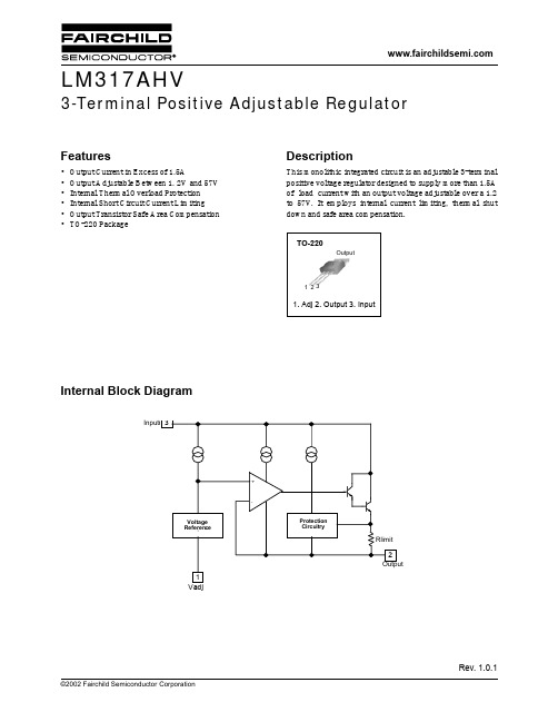
Description
This monolithic integrated circuit is an adjustable 3-terminal positive voltage regulator designed to supply more than 1.5A of load current with an output voltage adjustable over a 1.2 to 57V. It employs internal current limiting, thermal shut down and safe area compensation.
1. Life support devices or systems are devices or systems which, (a) are intended for surgical implant into the body, or (b) support or sustain life, and (c) whose failure to perform when properly used in accordance with instructions for use provided in the labeling, can be reasonably expected to result in a significant injury of the user.
DISCLAIMER
FAIRCHILD SEMICONDUCTOR RESERVES THE RIGHT TO MAKE CHANGES WITHOUT FURTHER NOTICE TO ANY PRODUCTS HEREIN TO IMPROVE RELIABILITY, FUNCTION OR DESIGN. FAIRCHILD DOES NOT ASSUME ANY LIABILITY ARISING OUT OF THE APPLICATION OR USE OF ANY PRODUCT OR CIRCUIT DESCRIBED HEREIN; NEITHER DOES IT CONVEY ANY LICENSE UNDER ITS PATENT RIGHTS, NOR THE RIGHTS OF OTHERS.v
电感全型号尺寸封装
1.63
0.26
HSM32-820K 82.0
1.82
0.23
HSM32-101K 100.0
2.41
0.20
HSM32-121K 120.0
2.72
0.18
HSM32-151K 150.0
3.12
0.16
HSM32-181K 180.0
3.67
0.15
HSM32-221K 220.0
4.99
0.14
5-21
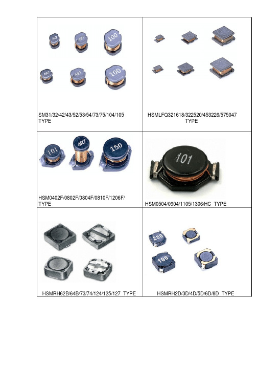
HSMLFQ321618/322520/453226/575047 TYPE HSM0402F/0802F/0804F/0810F/1206F/ TYPE HSM0504/0904/1105/1306/HC TYPE
22-28 29-36 37-41
HSMRH62B/64B/73/74/124/125/127 TYPE HSMRH2D/3D/4D/5D/6D/8D TYPE
开磁路设计具有大功率 .高饱和电流 ..低阻抗 .小型化之特点。
APPLICATIONS( 用途 )
Power supply for vtr,OA equipment Digiht camera ,LCD television set notebook PC,portable
communication
→EXTERNAL DIMENSION UNIT:mm( 外形尺寸 )
PART NO.
A
B
C
H
I
J
HSM31A
3.5± 0.3 3.0
±0.2 1.1
±0.3
3.5 1.6 0.8
HSM31B HSM32
3.5± 0.3 3.0 3.5± 0.3 3.0
SPD综合1
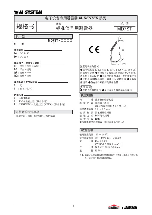
订货时的指定事项
·机型代码(例如 : MD7ST - 24FF00)
95
98 (mm)
主要的功能与特长 ●放电电流为 20 kA(8/20 µs)、1 kA(10/350 µs) 的超高容量型 ●厚度仅有7 mm的薄形避雷器,省空间, 适合用于多点保护 ●多极保护电路设计,保护性能优秀 ●使用金属 DIN 导轨扣,通过 DIN 导轨接地 ●备有屏 蔽端子 ●备有兼作断路开关的保险丝
有保险丝∶7.5 Ω ± 10 %(每条导线)
有保险丝∶12.5 Ω ± 10 %(每条导线)
适用标准
EC 指 令 : 电磁兼容指令(EMC指令)(89/336/EEC) EMI EN61000-6-4 EMS EN61000-6-2
浪涌保护性能 : IEC 61643-21(类别 C1、C2、D1)
接地端子(G) (兼安装固定端)
安装尺寸图(单位 : mm)
25以上
2-M4螺丝
北京森海瑞
8
规格书
电子设备专用避雷器 M-RESTER 系列
电池内置型、带寿命显示功能
※1、发信器的输出容量超过100mA时,需设置电路保护器。 ※2、本产品为信号保护用避雷器,保护电源时要另外使用电源保护用避雷器。
7
北京森海瑞
90
100 90 80
45
外形尺寸图(单位 : mm)·端子编号图
23.5 P+ P-
2-φ 5 安装孔 主机
80
53
27
底座
4 - M4 端子螺丝 S+ S-
伊顿电子产品参考手册说明书

提供动力。
探索今天的伊顿。
我们提供:• 方案• • •动及动力总成解决方案马达控制设备命令和控制设备终端保护产品自动化和驱动产品134MOEM 市场综合样本目录2马达和线路控制设备伊顿拥有超过百年的接触器研发和制造经验,为用户提供至3185A 的线路控制解决方案,并提供不同系列的产品以满足用户的的多种要求Xstart 系列接触器:全球化的产品,提供包括UL 在内的主流认证,最高达3185安培(AC-1)的产品:• 独特的CT 型励磁机构,功耗更小;• 115A 以上集成电子线路板,降低功耗同时工作电压幅度更宽;• 580A 以上真空灭弧,应对严苛使用环境,业界最长预期寿命;• 提供本地化的XstartC 系列(认证情况请咨询当地销售办事处)。
D 系列接触器:本地化的产品,提供最高到500A 的高效控制和保护方案,应用于泵、风机、压缩机等场合,提供功能全面的辅助触点和宽幅的控制线圈电压选项。
• 齐全的线圈控制电压,185A 以上更提供交直流通用产品;• 全系列内置辅助触点• 百万次以上电气寿命• 使用温度-20 °C ~ +55 °CE 系列接触器:全球最小的电磁接触器之一,有效地利用空间,可靠性增强,材料使用更高效。
E 系列接触器额定值可至AC-3, 95A@400V ,最高工作电压高达660V ,体积小巧,却提供强大的性能。
• 百万次以上电气寿命• 690V 绝缘额定值• 最多可加装6个辅助触点模块• 常用交流控制电压及直流24VDC 线圈1马达控制设备目录电机控制产品 xStart C 接触器式继电器DILA..C 接触器DILM..C 过载继电器ZB..C电动机保护断路器PKZMC 电机控制产品 D 系列接触器 XTCD 热过载继电器 XTOD 电气行业解决方案 Eline 控制继电器 XTRG 接触器 XTCG热过载继电器 XTOD/XTOG电机控制产品 xStart C电机控制产品 D 系列电气行业解决方案Eline1接触器式继电器DILA..C目录系统概览 . . . . . . . . . . . . . . . . . . . . . . . . . . . . . . . . . . . . . . . . . . . . . . . . . . . . . . . . . . . . . . . . . . . . .本体DILA..C . . . . . . . . . . . . . . . . . . . . . . . . . . . . . . . . . . . . . . . . . . . . . . . . . . . . . . . . . . . . . . . . . .辅助触点模块 . . . . . . . . . . . . . . . . . . . . . . . . . . . . . . . . . . . . . . . . . . . . . . . . . . . . . . . . . . . . . . . .附件 . . . . . . . . . . . . . . . . . . . . . . . . . . . . . . . . . . . . . . . . . . . . . . . . . . . . . . . . . . . . . . . . . . . . . . . . .操作电压 . . . . . . . . . . . . . . . . . . . . . . . . . . . . . . . . . . . . . . . . . . . . . . . . . . . . . . . . . . . . . . . . . . . . .特性曲线,触点行程图 . . . . . . . . . . . . . . . . . . . . . . . . . . . . . . . . . . . . . . . . . . . . . . . . . . . . . . . .技术数据 . . . . . . . . . . . . . . . . . . . . . . . . . . . . . . . . . . . . . . . . . . . . . . . . . . . . . . . . . . . . . . . . . . . . .尺寸 . . . . . . . . . . . . . . . . . . . . . . . . . . . . . . . . . . . . . . . . . . . . . . . . . . . . . . . . . . . . . . . . . . . . . . . . .4极触点多种组合约定发热电流(I th )16A 交流与直流操作的产品尺寸相同直流操作的产品内置浪涌抑制器••••接触器式继电器DILA..C35791112131911接触器式继电器DILA..C说明121接触器式继电器DILA..C系统概览31接触器式继电器DILA..C系统概览4系统概览本体AC 或DC 操作电磁系统AC DC 可以扩展到8对触点反向互锁触点模块化系统螺钉连接和卡装手指接触防护螺钉端子第5页起抑制电路用于直流操作接触器式继电器的保护电路(所有直流型均内置)用于交流操作接触器式继电器的保护电路第32页起辅助触点模块23, 42或4极反向互锁触点第7页起124 – 400V, 50, 60, 50/60 Hz0.8 – 1.1 × U c 24 VA/3.4 VA 24 – 220 V DC0.8 – 1.1 × U c 于24 V :0.7 – 1.3 × U c 无附加辅助触点模块环境温度+40°C 3W/3W1接触器式继电器DILA..C本体5接线方式:螺钉端子触点N/O = 常开N/C = 常闭带反向互锁触点的本体额定工作电流AC – 15220 V230 V240 VI e约定发热电流,敞开,于60°CI th代码序号触点序号380 V400 V415 VI e1本体DILAC-XHI(V)...DILAC-XHI(V)...DILAC-XHI(V)...DILA-40C(220-230V50Hz)114842DILA-31C(220-230V50Hz)114852DILA-22C(220-230V50Hz)114862DILA-40C(24VDC)114847DILA-31C(24VDC)114857DILA-22C(24VDC)1148671件1件1件可以组合辅助触点模块标准包装说明AC 操作型号订货号操作电压220-230V50HzDC 操作型号订货号操作电压24VDC附件1 抑制器2 辅助触点模块操作电压页数32711触点编号,符合EN 50011线圈端子标记,符合EN 50005直流操作的接触器式继电器具有一个内置的保护电路。
AZ 17 长寿命小体型多码位电缆孔盖 M16 双隔电保护 8个操作方向 30mm x 60mm x
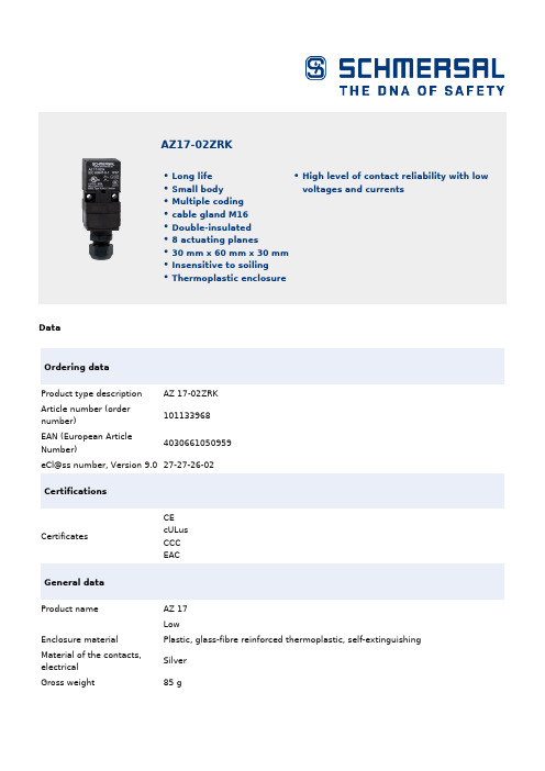
DataOrdering dataProduct type descriptionAZ 17-02ZRK Article number (ordernumber)101133968EAN (European ArticleNumber)4030661050959eCl@ss number, Version 9.027-27-26-02CertificationsCertificates CEcULusCCC EACGeneral dataProduct name AZ 17LowEnclosure materialPlastic, glass-fibre reinforced thermoplastic, self-extinguishing Material of the contacts,electricalSilver Gross weight 85 g AZ17-02ZRKLong lifeSmall bodyMultiple codingcable gland M16Double-insulated8 actuating planes30 mm x 60 mm x 30 mmInsensitive to soilingThermoplastic enclosure High level of contact reliability with low voltages and currentsGeneral data - Featureshigher Latching force YesNumber of safety contacts2Safety appraisalStandards ISO 13849-1Mission Time20 Year(s)Safety appraisal - Safety outputsB10d Normally-closed2,000,000 Operations contact (NC)Mechanical dataMechanical life, minimum1,000,000 Operations Latching force30 Npositive break travel11 mmPositive break force,17 NminimumActuating speed, maximum 2 m/sMechanical data - Connection techniqueTerminal Connector IDC method of termination Cable section, minimum 1 x 0.75 mm²Cable section, maximum 1 x 1 mm²Mechanical data - DimensionsHeight of sensor85 mmLength of sensor30 mmWidth of sensor30 mmAmbient conditionsProtection class IP 67 to IEC/EN 60529Ambient conditions - Insulation valueRated impulse withstand4 kVvoltageElectrical dataThermal test current10 AUtilisation category AC-15230 VACUtilisation category AC-15 4 AUtilisation category DC-1324 VDCUtilisation category DC-13 4 ASwitching element Opener (NC) Switching principle Creep circuit elementScope of deliveryIncluded in delivery Actuators must be ordered separately. Slot sealing plugsNotesNote (General)This type termination (IDC) method enables simple connetion of flexible conductors without the need for the use of conductor ferrulesOrdering codeProduct type description:AZ 17-(1)Z(2)K-(3)-(4)-(5)(1)11 1 NO contacts/1 NC contact 02 2 NC contact(2)without Latching force 5 NR Latching force 30 N(3)without M16 cable gland2243Front cable entry2243-1Rear cable entryST M12 connector, 4 pole(4)1637Gold-plated contacts(5)5M Cable length 5 m6M Cable length 6 mPicturesProduct picture (catalogue individual photo)ID: kaz17f16| 125,7 kB | .png | 74.083 x 177.094 mm - 210 x 502Pixel - 72 dpi| 183,8 kB | .jpg | 32 x 76.5 mm - 320 x 765 Pixel - 254dpi| 670,2 kB | .jpg | 221.192 x 529.167 mm - 627 x 1500Pixel - 72 dpiDimensional drawing basic componentID: 1az17g01| 3,7 kB | .png | 74.083 x 51.858 mm - 210 x 147 Pixel- 72 dpi| 32,7 kB | .cdr || 17,2 kB | .jpg | 112.889 x 79.022 mm - 320 x 224Pixel - 72 dpi| 67,0 kB | .jpg | 352.778 x 247.297 mm - 1000 x 701Pixel - 72 dpiSwitch travel diagramID: kaz17s02| 20,1 kB | .cdr || 16,2 kB | .jpg | 112.889 x 40.217 mm - 320 x 114Pixel - 72 dpi| 2,0 kB | .png | 74.083 x 26.458 mm - 210 x 75 Pixel -72 dpiDiagramID: k2o--k01| 17,0 kB | .jpg | 112.889 x 40.217 mm - 320 x 114Pixel - 72 dpiK.A. Schmersal GmbH & Co. KG, Möddinghofe 3, D-42279 WuppertalThe details and data referred to have been carefully checked. Images may diverge from original. Further technical data can be found in the manual. Technical amendments and errors possible.Generated on 08.07.2020 18:38:00。