HAPN.HPS2DN软驱说明书
伺服驱动器用户手册
2.2.2、通风间隔
2.2.3、安装方法 1)、安装方向:伺服驱动器的正常安装方向是垂直直立方向。 2)、安装固定:上紧伺服驱动器上的四颗 M5 固定螺钉。 3)、通风散热:采用自然冷却方式,在电气控制柜内必须安装散热风机。
z 拆装带轮时,不可敲击电机或电机轴,防止损坏编码器。应采用螺旋式压 拔工具拆装
z 驱动器端子 U、V、W 必须与电机 U、V、W 一一对应 z 用户在使用本产品时务必在设计与装配时考虑安全防护措施,以防止
因错误的操作引起意外事故 z 驱动器和电机必须良好接地 z 在拆卸本驱动器前,必须断电 5 分钟以上
3.1、标准接线
本交流伺服驱动器的接线与使用的电机和控制方式等有关。
10
3.1.1、与武汉华大、常州常华、常州新月 4 对极电机控制接线图 3-1,对南 京苏强 110SQMA4IE 系列 4 对极电机只需将 UVW 接电机的 423 脚 对应参数 P34=2360、P35=4
20A
30A
50A
75A
100A 150A
≤1.2KW
25A ≤3.7KW
≤2.3KW ≤3.7KW ≤5.5KW ≤7.5KW
AC380V -15%~+10%
50A
75A
≤7.5KW ≤11KW
≤11KW
工作:45℃
存贮:-40℃~55℃
40%~80%无结露 86-106kpa ①位置控制 ②JOG 控制 ③速度控制 ④转矩控制 ⑤位置和速度控制 ⑥内部脉冲控制 ⑦电动刀架控制 ⑧位置和转矩控制 ①脉冲+方向 ②CW+CCW 脉冲 ③两相 AB 正交脉冲 0.01% ≤200Hz ≥500kHz 1:5000 内置 1/30000~30000/1 ≥300% 2500p/r 电机转速、电机电流、电机转矩、电机位置、位置偏差、指 令脉冲数、脉冲频率、直线速度、输入输出诊断 超速、过流、过压、欠压、过载、超差、编码器故障、温度 过高、内部芯片故障、模块故障
山特士汽车连接器说明书

Samtec delivers Sudden Service® solutions for standard and customer-specific automotive designs by providing an array of options to meet the robust quality, production and compliance requirements of our customers. Our automotive interconnect systems are ideal for applications requiring high-performance, high-density, high-reliability / high mating cycles, optics and microelectronics solutions, with varying degrees of PPAP options.STANDARD CATALOG PRODUCT A-SERIES FOR AUTOMOTIVECATALOGACD-SERIESFORCUSTOMIZATIONCertified ISO-9001Built to Samtec’s drawing Sudden Samples for prototyping Short lead timesfor volumeCertified to IATF 16949to support Level 3PPAP requirements– Controlled IATF facility– Registered InternationalMaterial Data System (IMDS)Built to Samtec’sdrawings & standardsShort lead timesfor volumeCertified to IATF 16949to support all agreedupon customer specificrequirements– Controlled IATF facility– Registered InternationalMaterial Data System (IMDS)Vendor Managed Inventoryoptions for volume2From the technology systems inside the cabin, to sensor and lighting systems outside the cabin, designers can create, build and manufacture with the confidence of Samtec quality and support.DRIVER INFORMATIONSYSTEMS (DIS) / AUDIONavigation & TrackingRadar Controlled Cruise ControlGPSSatellite RadioEntertainment SystemsHeads-up Display SystemINTERIORPower Windows & SeatsSunroof, Moonroof ControlsDay / Night MirrorsInterior LightingNight Vision SystemClimate ControlCONTROLInstrument Panel & CockpitSteering ModulesBrake ModulesEngine Control SystemsPower Door LocksAutomatic Transmission (Tiptronic)SAFETYWarning SensorsAnti-theft SystemsSafety Trunk ReleaseHands Free SystemAirbag Release SystemEmergency CommunicationLidar & ADASIR Sensor & Camera Systems35G SOLUTIONS Connectors meet PPAP Level 3 process; cable assemblies are in process.Connectors meet PPAP Level 3 process.SEARAY ™ Open-Pin-Field Arrays EDGE RATE ® Rugged High-Speed Connector Strips SEARAY ™ High-Density Array Cable Assembly 50 Ω High-Frequency RF Flexible Cable Assembly AcceleRate ® Rugged Slim Body Cable Assembly Connected vehicles are the future of mobility. Leveraging next gen 5G networks and cloud services, V2X technologies enable vehicle intelligence, improve traffic flow and increase safety. Samtec’s expanding automotive interconnect portfolio helps route data from 5G radios to sensors throughout the vehicle. Combined with its IATF 16949 certification, Samtec offers technical expertise to support the unique challenges of automotive and transportation applications.CONNECTED VEHICLES V2H V2G V2I V2D V2V V2P E-Mobility is moving automotive technology forward, especially the need for power. Electric cars require DC-DC/AC-DC power conversion, and thermal management for durability and long-life, as well as energy storage and efficient ways to heat or cool the cabin. From charging stations and remote or mobile (vehicle-to-vehicle) charging to a full battery swap, users require options to quickly power their vehicles at home and on the road. Whether inside or outside of the vehicle, Samtec offers a wide variety of interconnects and high-power solutions to meet these needs.E-MOBILITY POWER SOLUTIONS mPOWER ™ Ultra Micro Power Connectors Mini Mate ® Rugged System with Individually Shrouded Contacts PowerStrip ™/30 Amp Signal/Power Combo System One–Piece 2.54 mm Pitch Rugged Interconnect 4FUTURE MOBILITYAutonomous vehicles are a rapidly advancing technology. To meet the industry needs, Samtec offers a broad line of interconnect solutions for all five levels of autonomy, from our Core Products to Silicon-to-Silicon Solutions for full channel signal integrity optimization.LEVEL 0 No Automation Full-time human driver for all aspects of driving.LEVEL 1 Driver Assistance Assistance of either steering or acceleration/deceleration with human driver for all other aspects of driving.LEVEL 2 Partial Assistance Assistance of both steering and acceleration/deceleration with human driver for all other aspects of driving.LEVEL 3 Conditional Automated Driving of all dynamic driving tasks with human driver responding to a prompt to intervene or take control.LEVEL 4 High Automation Automated Driving of all driving tasks under select conditions, without human driver input or oversight.LEVEL 5 Full Automation Full-time Automated Drivingunder all roadway andenvironmental conditions.CORE PRODUCTSOLUTIONSLEVELS 0-5 (PG 8-9)Rugged Tiger Eye™Contact SystemsFlexible Stacking SystemsOne-Piece SystemsMicro Pitch SystemsDiscrete Wire ComponentsSealed I/O SystemsSILICON-TO-SILICONSOLUTIONSLEVELS 3-5 (PG 6-7)High-Density ArraysRugged SI Edge Rate®Contact SystemsEdge Card SystemsGround Plane ConnectorsUltra Micro InterconnectsUltra Micro, High PowerInterconnectsHigh-Speed CableAssembliesRF Cables andComponentsHUMAN MONITORINGMACHINE MONITORING5 LEVELS OF AUTONOMY5HIGH-DENSITY ARRAYSSEARAY™ open-pin-field arrays for maximum grounding and routing flexibilitySEARAY™ 0.80 mm pitch arrays provide2x the density of 1.27 mm pitch arraysUp to 720 Edge Rate® contacts for 56 GbpsPAM4 performanceLP Array™ low profile arrays down to 4 mm Compatible with mPOWER™ for signal/power flexibilityEDGE RATE® SYSTEMSRugged Edge Rate® contacts are optimized for signal integrity performance and less prone to damage when “zippered” to unmate56 Gbps PAM4 rugged connectors with1.50 mm contact wipe on 0.80 mm pitchStack heights from 7 mm to 18 mmCompatible with mPOWER™ for signal/power flexibilityHIGH-SPEED EDGE CARD SYSTEMS 0.80 mm and 1.00 mm pitch with up to 200 total pins Vertical, right-angle and edge mountRugged edge card/power combinationLatches and weld tabs available GROUND PLANE CONNECTOR STRIPSSurface mount ground plane between signal rowsfor improved electrical performanceIntegral metal plane for power to 25 Amps Increased 1.20 mm contact wipe for a reliable connection in rugged applicationsCompatible with mPOWER™ for signal/power flexibility 6ULTRA-MICRO INTERCONNECTSRazor Beam ™ LP connectors on 0.40 mm and 0.50 mm pitchUltra low stack heights down to 2 mmRazor Beam ™ hermaphroditic connectors4-6x greater mating/unmating forces vs. typical micro pitch connectorsmPOWER ™ ULTRA MICRO POWER INTERCONNECTSMicro 2.00 mm pitch with up to 21 Amps per bladeDesign flexibility for power-only or power/signal applicationsSmall form factor allows space for other components on the boardSelectively loaded contacts for creepage and clearance requirements30 A solution in developmentHIGH-SPEED CABLE ASSEMBLIES0.80 mm pitch Edge Rate ® coax and twinax assembliesHermaphroditic Razor Beam ™ coax assemblies with rugged shielding0.50 mm and 0.80 mm pitch integral ground plane assembliesEye Speed ® cable for excellent signal integrity, small bend radii and dynamic high flexing cyclesACCELERATE ® SLIM BODY CABLE ASSEMBLIESSlimmest cable assembly in the industry at 7.6 mm body widthEye Speed ® ultra low skew twinax cableRugged metal latching system and shielded board level mateSupports 56 Gbps PAM4 applicationsRF CABLE AND COMPONENTSSMP and SMPM miniature push-on connectors to 65 GHzMicro-miniature interconnects with snap on-coupling; high vibration availableShielded twisted pair system with high-reliability contactsHigh frequency cable to 10 GHz with U.FL/W.FL compatible plugsSamtec’s Silicon-to-Silicon Solutions are available as standard catalog products and automotive A-Series, or customer-specific automotive ACD-Series. For more information or to discuss your specific automotive application, please contact *************************. 7FLEXIBLE STACKING SYSTEMS0.80 mm to 2.54 mm pitch systemsPass-through contacts to connect multiple boardsUp to six rows and 300 total pinsLow profile and skyscraper solutionsContact flexibilityONE-PIECE SYSTEMSRobust design and mechanical hold-downs for high shock and vibration applications1.00 mm and .100" (2.54 mm) pitchProfiles up to 10 mmVertical and right-angle applicationsTIGER EYE ™ CONTACT SYSTEMSHigh-reliability multi-finger, BeCu contact system for rugged environments and high cycle applications0.80 mm, 1.27 mm and 2.00 mm pitch systemsOptional ruggedizing features, including alignment pins, weld tabs and screw downsVertical and right-angle for parallel, perpendicularor coplanar applicationsCONTACT FLEXIBILITYTIGER CLAW ™Pass-ThroughTIGER EYE ™High-Reliability TIGER BUY ™High-Retention POWER EYEHigh-CurrentRUGGED FEATURES Friction LocksGuide Posts Screw Downs Alignment Pins 8MICRO PITCH SYSTEM0.50 mm pitch with up to 60 contacts Mitigates misalignment in X and Y directions Choice of body heightIdeal for multiple connectors on a board DISCRETE WIRE COMPONENTS 1.00 mm to 2.54 mm pitchdiscrete wire componentsHigh-reliability Tiger Eye™multi-finger BeCu contact systemMini Mate® rugged shroudeddiscrete wire componentsSingle and double rowRugged latching and polarizationACCLIMATE™ IP68 SEALED CIRCULAR SYSTEMS Kitted components (Field Termination Kits) for efficient field assemblyChoice of 12 mm (up to 5 A) or 16 mm (up to 11.6 A) metal or plastic shellsTerminals and sockets with 0.50 mm,1.00 mm or 1.50 mm diameter pinsInsertion tools and dust caps availableCUSTOM SOLUTIONS PinModificationsBodyModificationsCustomConnectorsPrototypingSpecialPlatingsTesting QualificationTestingSamtec’s Core Product Solutions are available as standard catalog products and automotive A-Series,or customer-specific automotive ACD-Series. For more information or to discuss your specific automotive application, please contact *************************.9CERTIFICATIONSSamtec is IATF 16949, ISO 14001 and ISO 9001 certified, and is fully integrated with in-house tooling, plating and automated manufacturing capabilities that provide for advanced development, low-cost, quick turn and high volume production. In addition, Samtec is compliant with International Traffic and Arms Regulations (ITAR) and with EU WEEE and RoHS directives. Please visit /quality for additional certification information.RoHS COMPLIANT LEAD FREE CERTIFIED COMPLIANT REACH COMPLIANT IMDS CERTIFIED ISO 14001CERTIFIED ISO 90011. INDEX PAGE2. SERIES DESIGN RECORD — SAMTEC RELEASED PRINT3. CHANGE HISTORY4. SERIES DESIGN FMEA5. PROCESS FLOW DIAGRAM6. PROCESS FMEA7. CONTROL PLAN — PRE-LAUNCH8. CONTROL PLAN — SERIAL PRODUCTION9. MEASUREMENT SYSTEM STUDIES (GAGE R&R) a. Total Gage R&R < 10% is acceptable b. Total Gage R&R >10% , <30% is acceptable for non-critical characteristics 10. ASSEMBLY DIMENSIONAL RESULTS (100% FAI & BALLOONED PRINT) a. Tabular Summary Format (according to AIAG manual) 100% layout for 5 parts for each cavity (1 cavity) 100% layout for 3 parts for each cavity (2 cavities) 100% layout for 2 parts for each cavity (3 or 4 cavities) 100% layout for 1 part for each cavity (6 or more cavities)b. Drawing numbered to correlate with submitted dimensional results and drawing notes PRODUCTION PART APPROVAL PROCESSSamtec uses proven processes that meet our IATF 16949 certification. Samtec designates these products with an A-Series part number. For each A-Series product, a customer will receive a Level 3 Product Part Approval Process (PPAP) package. Contents shown below are the supporting documents required to meet Level 3 PPAP .11. INITIAL PROCESS STUDY (SPC) Cpk > 1.67 or 100% in process inspection 12. COMPONENT PPAP 13. MATERIAL CERTIFICATION 14. QUALIFIED LABORATORY DOCUMENTATION 15. CAPACITY & RUN AT RATE DATA FORM — DATA FROM PRODUCTION TRIAL RUN Data must come from a minimum run of 300 parts 16. RUN @ RATE CHECKLIST17. EVIDENCE OF IMDS SUBMISSIONProof of submission into the International Material Data System 18. PART SUBMISSION WARRANT (PSW)19. FACILITY IATF CERTIFICATION GREEN: SUBMITTED, WHITE: RETAINED 10TESTINGSamtec automotive products are subject to a wide variety of test procedures, from standard testing to those that push the industry limits ensuring quality and durability in any application. Design Qualification Testing includes: Gas Tight, Normal Force, Thermal Aging, mating/unmating/durability, IR/DWV and Current Carrying Capacity (CCC).EXTENDED LIFE PRODUCT™E.L.P.™ products are tested to rigorous standards,which evaluate contact resistance in simulatedstorage and field conditions.• 10 year Mixed Flowing Gas (MFG)• High Mating Cycles (250 to 2,500)• Certain plating and/or contact options will apply• For complete details on Samtec's E.L.P.™program, a list of qualifying products andtest results, visit /ELP or emailthe Customer Engineering Support Groupat **************SEVERE ENVIRONMENT TESTINGSevere Environment Testing (SET) is a new Samtecinitiative to test our products beyond typical industrystandards and specifications, many set forth bycommon requirements for rugged industries. Severalof our products undergo additional testing to ensurethey are more than suitable for industrial, military,automotive and other extreme applications.Contact ************** for more information andtest results as available.TESTING INCLUDES:• Higher Mating Cycles with 100% Humidity• Intense Shock and Vibration: LLCR & Event Detection • Temperature Cycling• Non-Operating Class Temperature• DWV at High Altitude• Electrostatic Discharge (ESD)All Samtec products undergo Design Qualification Testing.SET and E.L.P.™ are complimentary tests in addition to DesignQualification Testing; visit for more information.Customer specific testing is also available; please contact************** for testing capabilities.PITCH TYPE CONTACT SERIES*0.50 mm Q Series® Strip Blade & Beam QSH/QTHBasic Strip Blade & Beam BSH/BTH0.635 mm Q Series® Strip Blade & Beam QSS/QTSBasic Strip Blade & Beam BSS/BTS 0.80 mmEdge Rate® Strip Edge Rate®ERF8/ERM8Edge Card Edge Rate®HSEC8Q Rate® Strip Edge Rate®QRM8/QRF8Q Series® Strip Blade & Beam QSE/QTEBasic Strip Blade & Beam BSE/BTEStrip Tiger Eye™SEM/TEM 1.00 mm Strip Tiger Claw™CLM/FTMH1.27 mmSEARAY™ Array Edge Rate®SEAF/SEAMStrip Tiger Eye™SFM/TFMStrip Tiger Claw™CLP/FTSHStrip Tiger Beam™FLE/FTSH2.00 mm Strip Tiger Eye™SMM/TMMStrip Tiger Claw™CLT/TMMH2.54 mm Strip Tiger Claw™SSM/TSMStrip Tiger Claw™BCS/TSW * Tested socket/terminal combination shown. Other mating headers also available. Contact Samtec if header design you need is not shown.DESIGN QUALIFICATION TESTING10 YEAR MFGEXTENDED LIFEPRODUCTHIGH MATINGCYCLES11© AUGUST 2019, SAMTEC INC.SU D D ENSA M P LEFREE SAMPLES IN 24 HOURSWORLD DIRECT2-DAY SHIPPING TO ALL MAJOR MARKETS3-DAY SHIPPING OF MOST PRODUCTS#1 CONNECTOR MANUFACTURER BISHOP & ASSOCIATESSUPPORT CENTERS MANUFACTURING SALESSAMTEC CABLENEW ALBANY, INDONGGUANCOSTA RICAPENANG JOHORSINGAPOREVIETNAMSAMTEC TOOLSIGNAL INTEGRITY GROUPTUCSON DESIGN CENTERCOLUMBIA DESIGN CENTER SAMTEC OPTICAL GROUPSAMTEC MICROELECTRONICSSCOTTSBURG, INHUIZHOUTAIWANBELGIUMJAPAN。
中、高压固态软起动器HPMV-DN操作指导说明书

使用操作指导说明书中、高压固态软起动器HPMV-DN换脸安全● 操作本设备之前,请仔细阅读操作指导手册并严格遵循手册的操作规范。
● 安装及维护操作,应严格按照本手册及相关国家标准及行业惯例,否则因没有按照相应指导规范操作所引起的一切不良后果制造商概不负责。
● 维护软起动器或电机之前,必须断开一切电源输入。
● 安装后应仔细检查核实无任何零部件(如:螺钉、垫圈等)落入带电器件部位。
注意事项1、本产品设计依据IEC947-4-2A类设备等级标准要求。
2、进一步的信息详见技术说明。
警告● 本产品与主电源连接后其内部局部器件及PCB上局部位置所带的电压等同于主电压,若违规接触它将非常危险,可引起触电伤亡事故。
● 本产品接上主电源后,即使断开控制电压或停止起动器后,在软起动器的输出端仍然会出现用于采样的全电压信号。
● 产品必须要良好接地,以保证正常操作的安全,不致发生意外触电击伤。
● 禁止将功率因数补偿电容器连接在起动器输出端。
本公司保留改进产品设计及修改相关技术说明而不预先通知之权利!1目录主题起动器选型安装说明内部设定控制端子操作面板控制端子控制接线接线图柴油发电机供电的接线图带通讯的接线图起动停止参数电机和起动器保护电机和起动器故障查询表前面板显示模式参数设置低压检测(测试)泵起停参数设置起动程序菜单描述故障分析技术总结34-56-78-91011-12131415-1617-1819-2021-22232425-3233343536-3839-4041-42页码2HPMV-DN中压固态软起动器是最新一代完美可靠的高科技产品,是专门为标准中压三相三线鼠笼感应式电机设计的高科技产品。
为电机提供最佳的限流降矩起动方式。
HPMV-DN中压固态软起动器的起动方式是向电机提供平缓渐增的电压来完成的,从而实现了以起动电机所需的最小电流来平稳加速起动电机。
HPMV-DN是基于第三代数字微处理器基础上设计的,具有泵控制功能,全面的电机保护以及模拟输出等功能。
HMServo V2.0上位机软件说明书(中文版)

伺服驱动器上位机软件HMServo说明书(V 2.0)目录1 软件概述 (3)1.1 软件介绍 (3)1.2 软件功能 (3)1.2.1 系统名称 (3)1.2.2 核心功能 (3)2 软件使用 (4)2.1 参数配置功能 (4)2.1.1 基本配置 (4)2.1.2 电机编码器反馈配置 (5)2.1.3 电机参数设置 (8)2.1.4 参数计算 (10)2.1.5 温度保护/Brake功能设置 (10)2.1.6 Endat编码器电机Initphase (11)2.2 三环设置功能 (12)2.2.1 电流环设置 (12)2.2.2 速度环设置 (13)2.2.3 位置环设置 (14)2.3 自动换相功能 (15)2.4 波形监测功能 (18)2.5 波形分析功能 (20)2.6 数字IO功能 (21)2.6.1 数字输入信号配置 (21)2.6.2 数字输出信号配置 (21)2.7 固件更新功能 (22)2.8 参数管理功能 (23)2.9 用户自定义轨迹功能 (24)2.9.1 UDM主界面 (24)2.9.2 UDM Function简介 (26)2.9.3 常用UDM函数详解 (27)2.10 高级操作面板 (37)2.11 急停功能 (38)3 操作实例 (39)4 常见问题(FAQ) (40)1 软件概述1.1 软件介绍HMServo V2.0是大族电机伺服驱动器系列产品的上位机软件,支持大族电机所有型号的伺服驱动器的联机调试功能,目前所支持的型号有:●ST3-S-4/230Vac●ST3-S-15/380Vac●ST3-S-30/380Vac●ST3-S-50/380Vac●ST3-S-15/150Vdc●ST3-S-6/220Vac共6款驱动器,功率涵盖从500W到30kW ,其中ST3-S-15/150Vdc是直流供电高性能驱动器,其他型号为交流供电高性能驱动器;驱动器型号各字段的含义见具体型号硬件说明书。
汉邦斯HBS系列高性价比步进电机驱动器 - 汉邦斯科技说明书

Alarm Signal: OC output signal, active when one of the following protection is activated: over-voltage, 3 ALM+ O over current and position following error. This port can sink or source 20mA current at 24V. In default,
6 ENA- I level for enabling.The active level of ENA signal is software configurable.
Pin Name I/O
Stator Signal Connector – Screw Terminal Description
1 Pend+ O In-position Signal: OC output signal, active when the difference between the actual position and the command position is zero. This port can sink or source 20mA current at 24V. The resistance between Pend+ and Pend- is active at high impedance.
Right of techn. modifications is reserved
2
Technische Änderungen vorbehalten, 11.05.13
HYBRID STEPPER DRIVER HBS86H
h系列伺服驱动器使用手册

h系列伺服驱动器使用手册伺服驱动器是一种用于控制电机瞬时电流和位置的装置,广泛应用于机械设备、自动化系统和工业领域。
H系列伺服驱动器是一款高性能的伺服驱动器,具备稳定性、精准性和可靠性。
本使用手册将详细介绍H系列伺服驱动器的技术参数、连接方式、参数调节和故障排除等内容,以帮助用户正确、高效地使用H系列伺服驱动器。
一、技术参数H系列伺服驱动器的技术参数直接影响其性能和应用范围。
在本章节中,我们将详细介绍H系列伺服驱动器的输入电压、额定电流、保护等级、通信接口等重要参数。
请用户在使用前仔细阅读,并根据实际需求进行正确设置。
二、连接方式正确的连接方式对于伺服驱动器的性能和稳定性至关重要。
在本章节中,我们将详细介绍H系列伺服驱动器的电源连接、控制信号连接和电机接线等内容。
请用户按照说明书中的连接图进行连接,并确保连接牢固可靠。
三、参数调节H系列伺服驱动器具备多项参数可调节功能,以满足用户对于电机控制的个性化需求。
在本章节中,我们将详细介绍H系列伺服驱动器的参数设置方法和参数含义。
请用户在调节参数时,结合实际需要和设备要求,适当调整参数值,并注意保存参数设置。
四、故障排除在使用过程中,可能会遇到各种故障和问题,影响伺服驱动器的正常工作。
在本章节中,我们将列举常见的故障现象和解决办法,以帮助用户快速定位故障原因并进行修复。
请用户在遇到故障时,按照故障排除流程进行检查和修复,并及时与售后服务联系以获取更多的支持。
五、常见应用场景H系列伺服驱动器广泛应用于各种机械设备和自动化系统中,以提供精准的位置和速度控制。
在本章节中,我们将介绍H系列伺服驱动器在机床、工业机器人、包装设备和印刷机等领域的应用案例。
请用户参考这些案例,了解伺服驱动器在不同场景下的应用特点和优势。
六、维护和保养正确的维护和保养可延长H系列伺服驱动器的使用寿命和性能稳定性。
在本章节中,我们将介绍H系列伺服驱动器的日常维护方法和保养事项。
请用户按照说明书中的建议,及时进行维护和保养,以确保伺服驱动器的正常工作。
U2NAS-2 中文说明书

声 明首先感谢您选择购买并使用本产品,为了您能够更好的使用本产品的所有功能,请您在正式使用本产品前仔细阅读本手册内所提及的在产品使用过程中应注意的事项以及详细功能操作说明。
本手册内所描述之产品组件已申请并注册国家专利,任何仿冒均属侵权行为,须承担牵连之法律责任。
本产品组件符合国家低压电子产品安全标准。
本产品机身及包装盒标贴的专有系列号码标签是产品保修时的重要凭证,当产品需要保修时,用户需出示产品的系列号条码标签。
如果该标签遭到破坏,无法辨认或撕毁,本公司将不予保修。
本产品享有三个月保换,二年免费保修的售后服务。
本产品并非所有的环境都适合于产品的使用;本公司仅对产品本身质量按照本公司承诺的保修条款提供售后服务,因为技术上或者其他外部因素导致本产品设计规格上的变更,本公司将不再另行单独通知。
免除义务条款¾铁威马(Terra Master)对因地震、雷电等自然灾害、不是因为铁威马(Terra Master)的责任而发生的火灾、第三方操作、失盗、损坏、意外事故等,或在不正常情况下使用(如不正常的操作、误操作或其他问题)引起的损失不承担任何责任。
¾铁威马(Terra Master)对因故不能使用本产品或使用本产品而带来损失(利润损失、工作中断等)不承担任何责任。
¾铁威马(Terra Master)对因未遵守本使用说明书而引起的任何损失不承担任何责任。
¾铁威马(Terra Master)对因与铁威马(Terra Master)无关的设备或软件结合使用而引起的故障造成的任何损失不承担任何责任。
¾铁威马(Terra Master)对硬盘的损坏以及数据的丢失不承担任何法律责任。
¾铁威马(Terra Master)对软件使用界面与实际产品不符合、软件BUG未及时升级、说明书内容、光盘内容等与实际产品不符甚至不能操作,主机按键标识与实际有误等不承担任何有关法律的责任。
交流伺服电机驱动器说明书H N技术应用手册第 版
伺服驱动器的安装环境和方法及安全检查 伺服驱动器所有参数的说明 伺服驱动器的控制功能介绍 伺服驱动器的试运行操作说明 应用过程中出现的异常及排除方法
本手册可适用使用者如下:
安装及配线人员 系统试运行调机人员 检查和维护人员
II
安全注意事项
交流伺服驱动器
使用环境
◆禁止将本系列产品暴露在有水气、腐蚀性气体、可燃性气体等物质的场合使用,否则 会导致触电或火灾。 ◆禁止将本产品应用于有阳光直射、粉尘、盐粉及金属粉末较多的场合。 ◆禁止将本系列产品应用于有油及药品附着或者滴落的场合。
安装
◆请确认接地端子接地良好,接地电阻小于 100 欧姆。 ◆本产品适用电源为有效值 220V 的交流电源,请勿将 380V 三相交流电直接接入。 ◆驱动器的 U、V、W 为输出端,应与电机相连接,请勿将其与输入电源相连接。 ◆驱动器 U、V、W 三相输出与电机的三相输入端连接时,切勿接错相序。 ◆配线时,请参照线材选择指示进行配线,否则可能造成火灾。
第三章 信号接口及接线 ...................................................................................................... 8
3.1 概述................................................................................................................... 8 3.2 CN1 接口 .......................................................................................................... 8
SDX-2P超长距离HDBaseT双DVI-D、双RS232、音频、USB键盘和鼠标扩展器说明书
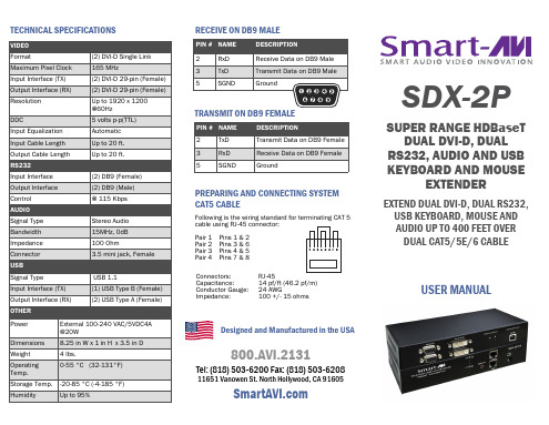
SDX-2P-TX Back
SDX-2P-RX Front
SDX-2P-RX Back
11651 Vanowen St. North Hollywood, CA 91605
SDX-2P
SUPER RANGE HDBaseT DUAL DVI-D, DUAL
RS232, AUDIO AND USB KEYBOARD AND MOUSE
EXTENDER
EXTEND DUAL DVI-D, DUAL RS232, USB KEYBOARD, MOUSE AND AUDIO UP TO 400 FEET OVER DUAL CAT5/5E/6 CABLE
The SDX-2P also has USB keyboard and mouse, audio and RS232 extension, giving you the ability to control your displays or devices remotely.
FEATURES
Extends dual DVI-D up to 400 feet (120m) from the source
(2) DVI-D Single Link 165 MHz (2) DVI-D 29-pin (Female) (2) DVI-D 29-pin (Female) Up to 1920 x 1200 @60Hz 5 volts p-p(TTL) Automatic Up to 20 ft. Up to 20 ft.
port on the SDX-2P-TX. 4. Optionally connect RS232 for control functions. 5. Connect the SDX-2P-TX to the SDX-2P-RX with
ABB 软启动器 PS D 和 PS DH 产品说明书

Softstarter range type PSD & PSDH2ABB Automation Technology Products AB/ Control, Id No: 1SFC132002C0201, March 2003Softstarters type PS D and PS DHABB’s solid state starter range is used when it is important to have a smooth start-up of various types of motor drives.Instead of switching directly to full voltage the softstarter ensures a gradual voltage increase.ABB’ s Softstarter is available in four versions, PS 75…840and PS DH 30…720.PS D 75…PS D 840 and PS DH 30…PS DH 720 softstart-ers have a robust design in metal housing for many types of applications, both normal duty and heavy duty. Flexible parameter settings with potentiometers and clear indication with LEDs of status and faults on front of the unit. Theoptional built in advanced electronic overload relay (always included as standard for PS DH versions) provides much better motor protection than a conventional bimetallic relay,for example in intermittent duty.DescriptionThe operator panels for PS DH have LED´s, potentiometers and switches for indication and settings.1S F T 98899-032Quck guide for selectionBy using the guide below you can quickly select a suitable ABB Softstarter for the most common applictions. If a more precise selection is required you can use Prosoft, a selection software available at /lowvoltage.3ABB Automation Technology Products AB/ Control, Id No: 1SFC132002C0201, March 2003Motor power Rated220-230 V 380-400/415 V 500 V 690 Vmotor current Order codeP e P e P e P e I e Type Supply voltage U s Supply voltage U s kWkWkWkWAPS D110-127 V,50/60 Hz220-240 V,50/60 Hzkg2237––28–757510––45–28-7575103055––70–1101101SFA 88 4205-F 1SFA 88 4205-L 11––75–70–110110113775––87.5–14514513––90–87.5–145145134590––105–17517525––110–105–1751752555110––140–21021028––132–140–2102102875132––140–25025028––160–140–2502502890160––175–30030028––200–175–30030028110200––210–37037051––250–210–37037051–––355100–3703701SFA 88 6211- A51132250––280–47047051––315–280–47047051–––450250–4704701SFA 88 6212- A 51160315––350–57057054––400–350–57057054–––560300–5705701SFA 88 6213-1SFA 88 6213-A 54200400––420–72072054––500–420–72072054–––710375–7207201SFA 88 6214-1SFA 88 6214-A 64250450––525–84084064––560–525–84084064–––800500–8408401SFA 88 6215-1SFA 88 6215-A 64Ordering data Softstarter PS D 75 (840)PS D 75…840 For normal startsWeight4ABB Automation Technology Products AB/ Control, Id No: 1SFC132002C0201, March 2003Ordering data Softstarter PS DH 30 (720)Motor power Rated 220-230 V 380-400/415 V 500 V motor current Order codeP e P e P e I e Type Supply voltage U s Supply voltage U s WeightkWkWkWAPS DH110-127 V,50/60 Hz220-240 V,50/60 Hzkg7.515–14–30301SFA 88 4301-B 1SFA 88 4301-10––18.514–30301SFA 88 5301-B 1SFA 88 5301-101522–28–45451SFA 88 4302-B 1SFA 88 4302-10––3028–45451SFA 88 5302-B 1SFA 88 5302-1018.530–35–60601SFA 88 4303-B 1SFA 88 4303-10––3735–60601SFA 88 5303-B 1SFA 88 5303-102237–42–75751SFA 88 4304-B 1SFA 88 4304-11––4542–75751SFA 88 5304-B 1SFA 88 5304-113055–70–1101101SFA 88 4305-B 1SFA 88 4305-13––7570–1101101SFA 88 5305-B 1SFA 88 5305-133775–87.5–1451451SFA 88 4306-B 1SFA 88 4306-25––9087.5–1451451SFA 88 5306-B 1SFA 88 5306-254590–105–1751751SFA 88 4307-B 1SFA 88 4307-28––110105–1751751SFA 88 5307-B 1SFA 88 5307-2855110–140–2102101SFA 88 4308-B 1SFA 88 4308-28––132140–2102101SFA 88 5308-B 1SFA 88 5308-2875132–140–2502501SFA 88 4309-B 1SFA 88 4309-28––160140–2502501SFA 88 5309-B 1SFA 88 5309-2890160–175–3003001SFA 88 4310-B 1SFA 88 4310-52––200175–3003001SFA 88 5310-B 1SFA 88 5310-52110200–210–3703701SFA 88 4311-B 1SFA 88 4311-52––250210–3703701SFA 88 5311-B 1SFA 88 5311-52132250–280–4704701SFA 88 4312-B 1SFA 88 4312-55––315280–4704701SFA 88 5312-B 1SFA 88 5312-55160315–350–5705701SFA 88 4313-B 1SFA 88 4313-55––400350–5705701SFA 88 5313-B 1SFA 88 5313-55200400–420–7207201SFA 88 4314-B 1SFA 88 4314-65––500420–7207201SFA 88 5314-B1SFA 88 5314-65PS DH 30...720 For heavy duty starts* For 690V red code letters are used.5ABB Automation Technology Products AB/ Control, Id No: 1SFC132002C0201, March 2003General technical dataGeneral technical data PS D 75...840 and PS DH 30 (720)PS D 75 (145)PS D 175 (840)PS DH 30 (110)PS DH 145 (720)Rated insulation voltage U i V 690690690690Rated operational voltage U e V 220–500220–690220–500220-500Starting capacity at max rated current I e4,5 x I e for 14s5 x I e for 7s 5 x I e for 25s 5 x I e for 25s Number of starts per hour6 4) 3 4) 6 4) 1 4)Overload capacity Overload class A 10103030Service factor %100100100100Ambient temperature During operation 1)°C 0 – 500 – 500 – 500 – 50During storage°C -40 – +70-40 – +70-40 – +70-40 – +70Degree of protectionIP 00IP 00IP 00IP 00SettingsRamp time during start sec 0.5 – 600.5 – 600.5 – 600.5 – 60Initial voltage during start %10 – 6010 – 6010 – 6010 – 60Ramp time during stopsec 0.5 – 2400.5 – 2400.5 – 2400.5 – 240Step down voltage special ramp %100 – 30100 – 30100 – 30100 – 30Current limit function2 – 5 x I e 2 – 5 x I e 2 – 5 x I e 2 – 5 x I e Adjustable rated motor current I e 2)%70 – 10070 – 10070 – 10070 – 100Switches forEnergy saving function ON/OFF (PF)Yes Yes Yes Yes Kick start, YES/NO(KICK)Yes Yes Yes Yes High current switch off, YES/NO (SC)Yes Yes Yes Yes Reaction time for energy saving normal/slow(TPF)Yes Yes Yes Yes Signal relays Fault signalK6Yes Yes Yes Yes By-pass signal, start ramp completed K5Yes Yes Yes Yes Run signalK4Yes Yes Yes Yes Overload signalYes Yes Yes Yes Rated operational voltage U e V 250250250250Rated thermal current I thA 5555Rated operational current I e at AC-15 (U e =250V)A1.51.51.51.5Signal indication (LED)Fault (F1 and/or F2) red Yes Yes Yes Yes Overload (OVL) yellow 3)Yes 3)Yes 3)Yes Yes Ready to start/stand by (ON) green Yes Yes Yes Yes Running (R) yellow Yes Yes Yes Yes Completed start ramp (T) yellow Yes Yes Yes Yes Energy saving function active (P) yellow Yes Yes Yes Yes1) Above 40 °C, up to max 50 °C, reduce the rated current with 0.8 % per °C. 2) For U e = 690 V; setting 50 – 100 %. 3) Optional for PSD types.4) When more than stated starts per hour are required, contact your sales office.Cross section of connection cables PS D and PS DHType PS D 75110...145175...570720840Type PS DH 30 (60)75 (110)145 (470)570720Main circuitConnection clampCu-cable mm 235––––Al-cable mm 235––––Connection barWidth x thickness mm –15x425x640x650x6Hole diameter mm –7111111Tightening torque min.Nm 2.5 2.4(M6)12.0(M10)12.0(M10)12.0(M10)(For guidance only)max.Nm 3.0 3.2(M6)16.0(M10)16.0(M10)16.0(M10)Supply and control circuit Connection clampmm 22.52.52.52.52.56ABB Automation Technology Products AB/ Control, Id No: 1SFC132002C0201, March 2003Recommended ABB Power re-Overload protection Maxquirements Current rangepower loss of supply at max /e Max fuse rating main circuit 4)circuit SizeTypeAWBussman fusesFerraz fusesVAPS S03TA 25 DU 2.2–3.1–16 A 170M1359212TA 25 DU 10–14–40 A 170M1363225TA 25 DU 18–25–50 A 170M13645PS S18/30TA 25 DU 6–183)50 A 170M13645)63 A 6.6 URB 000 D08 V 0063930/52TA 25 DU 10–303)80 A 170M13665)100 A 6.6 URB 000 D08 V 0100937/64TA 42 DU 22–373)125 A 170M13685)160 A 6.6 URB 000 D08 V 0160944/76TA 75 DU 29–443)160 A 170M13695)200 A 6.6 URD 30 D08 A 0200950/85TA 75 DU 29–503)160 A 170M13695)200 A 6.6 URD 30 D08 A 02001060/105TA 75 DU 29–603)200 A 170M13705)250 A 6.6 URD 30 D08 A 02501072/124TA 75 DU 45–723)250 A 170M13715)315 A 6.6 URD 30 D08 A 03151085/147TA 110 DU 65–853)315 A 170M13725)400 A 6.6 URD 30 D08 A 040036105/181TA 110 DU 65–1053)400 A 170M30196)400 A 6.6 URD 30 D08 A 040036142/245TA 200 DU 100–1423)450 A 170M30206)500 A 6.6 URD 30 D08 A 050036175/300TA 200 DU 100-1753)500 A 170M30216)530 A 6.6 URD 30 D08 A 055065250/430TA 450 DU 130-2503)700 A 170M40176)630 A 6.6 URD 31 D08 A 063065300/515TA 450 DU 130-3003)900 A 170M50156)900 A 6.6 URD 32 D11 A 090065PS D75TA 75 DU 7)45–753)250 A 170M13715)315 A 6.6 URD 30 D08 A 031540110TA 110 DU 7)65–1103)315 A 170M13725)400 A 6.6 URD 30 D08 A 040040145TA 200 DU 7)100–1453)400 A 170M30196)400 A 6.6 URD 30 D08 A 050040175TA 200 DU 7)100–1752)450 A 170M30206)500 A 6.6 URD 30 D08 A 050065210TA 450 DU 7)130–2102)500 A 170M30216)530 A 6.6 URD 30 D08 A 055065250TA 450 DU 7)130–2502)630 A 170M40166)550 A 6.6 URD 31 D08 A 055065300TA 450 DU 7)130–3002)700 A 170M40176)630 A 6.6 URD 31 D08 A 063065370TA 900 DU 7)265–3702)900 A 170M50156)900 A 6.6 URD 32 D11 A 090090470TA 900 DU 7)265–4702)900 A 170M50156)1250 A 6.6 URD 33 D11 A 125090570TA 900 DU 7)265–5702)1500 A 170M60186)1250 A 6.6 URD 33 D11 A 125090720TA 900 DU 7)465–7202)1800 A 170M60206)2000 A 6.6 URD 233 PLAF 200090840TA 900 DU 7)465–8402)1800 A170M60206)2000 A6.6 URD 233 PLAF 200090PS D(690V)370TA 450 DU 130–3702)900 A 170M50156)900 A 6.6 URD 32 D11 A 090090470TA 900 DU 265–4702)1250 A 170M50186)1250 A 6.6 URD 33 D11 A 125090570TA 900 DU 265–5702)1500 A 170M60186)1250 A 6.6 URD 33 D11 A 125090720TA 900 DU 465–7202)1500 A 170M60186)2000 A 6.6 URD 233 PLAF 200090840TA 900 DU465–8402)1500 A 170M60186)2000 A 6.6 URD 233 PLAF 200090PS DH301)3)125 A 170M13685)160 A 6.6 URD 30 D08 A 016040451)3)200 A 170M13705)200 A 6.6 URD 30 D08 A 020040601)3)250 A 170M13715)250 A 6.6 URD 30 D08 A 025040751)3)315 A 170M13725)315 A 6.6 URD 30 D08 A 0315401101)3)400 A 170M30196)450 A 6.6 URD 30 D08 A 0450401451)2)450 A 170M30206)500 A 6.6 URD 30 D08 A 0500651751)2)500 A 170M30216)550 A 6.6 URD 30 D08 A 0550652101)2)630 A 170M40166)630 A 6.6 URD 31 D08 A 0630902501)2)700 A 170M40176)700 A 6.6 URD 32 D08 A 0700903001)2)900 A 170M50156)900 A 6.6 URD 32 D08 A 0900903701)2)900 A 170M50156)1000 A 6.6 URD 33 D08 A 1000904701)2)1250 A 170M50186)1250 A 6.6 URD 33 D08 A 1250905701)2)1500 A 170M60186)1600 A 6.6 URD 33 TTF A 1600907201)2)1800 A 170M60206)2000 A 6.6 URD 233 PLAF 200090Technical data1) Electronic overload relay built in, class 305) Fuse holder 170H 10072) Total power loss: P Ltot = [3 x I e x 1.0] + 100 (W) Reduced to 100 W only when using by-pass 6) Fuse holder 170H 30043) Total power loss: P Ltot = [3 x I e x 1.0] + 50 (W) Reduced to 50 W only when using by-pass 7) Not required if using the optional electronic o.l.4) For the supply circuit: 6 A delayedSize related data7ABB Automation Technology Products AB/ Control, Id No: 1SFC132002C0201, March 2003DimensionsPS D 75PS DH 30 (60)PS D 370...840PS DH 300 (720)PS D 110...145PS DH 75 (110)PS D 175...300PS DH 145 (250)1S F T 98899-0141S F T 98899-0191S F T 98899-0181S F T 98899-0151S F T 98899-020 e d .21S F T 98899-021All dimensions in the table +/- 5 mmDimensionTypeE F K L M N PS D370…570PS DH300…47033.52562.5125173.526PS D720PS DH570414060110173.55PS D840PS DH720465060100173.551S F T 98899-027Dimensions Type No.E F G H PS D75PS DH30...60280360313218PS D110...145PS DH75...110280*********PS D175...300PS DH145...250382444402310PS D370...840PS DH300 (720)540600600310Minimum distance to wall/front A = 20 mm B = 10 mm C = 100 mm Both top and bottom D = 150 mm Both top and bottomMinimum distance to wall/front8ABB Automation Technology Products AB/ Control, Id No: 1SFC132002C0201, March 2003Circuit diagramsE1Circuit board E3–E5FanF6Temperature monitor J1–J3Contact blocks K4Relay, actuated in operational position K5Relay, actuated at full voltage (U e = 100 %)K6Relay, fault signal T2Current transformer T5Control transformerV1–V6Thyristor X1–X3Terminal blockPS D without electronic overload relayE1Circuit board E2Circuit board OVL E3–E5Fan F6Temperature monitor J1–J3Contact blocks K3Relay, overload K4Relay, actuated in operational position K5Relay, actuated at full voltage (U e = 100 %)K6Relay, fault signal T2Current transformer T3Current transformer T5Control transformerV1–V6Thyristor X1–X3Terminal blockPS D and PS DH with electronic overload relay1S F T 98899-0241S F T 98899-025。
埃森平衡变频驱动器 HMX34AG20522-N 商品说明说明书

Eaton HMX34AG20522-NH-Max Drive, 150 hp, 205A, 380-480V, Open NEMA Type 2 IP54, No brake chopper, Software A, Three-phase, Graphical panel keypad, EMC C2 input, Frame size 8General specificationsEaton H-Max variable frequency drive HMX34AG20522-N 78668547384013.76 in 38.02 in 11.42 in 154.3 lbEaton Selling Policy 25-000, one (1) year from the date of installation of the Product or eighteen (18) months from the date of shipment of the Product, whichever occurs first.CE MarkedUL 508C EN 61800-5-1 cUL Certified IEC 61800-5-1All boards are varnished. Corrosion resistant. Battery included in all drives for real-time clock. Keypad kit includes HOA bypass. Keypad kit includes HOA, back reset for Europe application. EMI/RFI filters included. DC link choke included.Product NameCatalog Number UPCProduct Length/Depth Product Height Product Width Product Weight WarrantyCompliances Certifications Catalog NotesEaton Corporation plc Eaton House30 Pembroke Road Dublin 4, Ireland © 2023 Eaton. All Rights Reserved. Eaton is a registered trademark.All other trademarks areproperty of their respective owners./socialmediaFR8EMC C2Three-phase No brake chopper 150 hp Graphical panel Type A Open NEMA 2 IP54380-480 V 205AVariable frequency drive - Product overview Eaton H-Max HVAC Drives Eaton's Volume 6—Solid-State Motor Control HMX_(FR8)2D PDFHMX_(FR8) AutoCAD 2D Footprint HMX_(FR8) 3D Model Xchange HMX_(FR8) AutoCAD 2D Footprint (mm)HMX_(FR8) 3D Inventor HMX_(FR8) 2D Drawing Xchange H-Max Series Adjustable Frequency Drive Installation Manual Eaton Specification Sheet - HMX34AG20522-NFrame size Input Phase Brake chopper Horsepower Keypad Software EnclosureVoltage rating Amperage Rating BrochuresCatalogsDrawings Installation instructionsSpecifications and datasheets。
hsha025a驱动器说明书

hsha025a驱动器说明书第一章:产品概述HSHA025A驱动器是一种用于驱动电机的设备。
它具有高效、稳定、可靠的特点,可广泛应用于工业自动化、机器人、医疗设备等领域。
本说明书将介绍HSHA025A驱动器的主要特点、技术规格以及使用方法。
第二章:技术规格1.输入电压:AC220V2.输出电压范围:DC0-220V3.输出电流范围:0-5A4.控制方式:模拟控制、数字控制5. 外形尺寸:150mm*100mm*50mm6.工作温度:-20℃~60℃7.防护等级:IP20第三章:安装与连接1.在安装之前,请确保所有电源已经关闭,并且拔出插头,以避免电击或设备受损。
2.驱动器应安装在通风良好、干燥的环境中,远离热源和腐蚀性气体。
3.请按照正确的接线方式连接电源和电机,确保接线牢固可靠。
4.在驱动器工作时,不要随意拔下或插上电缆,以避免电击或设备故障。
第四章:使用方法1.HSHA025A驱动器有两种控制方式:模拟控制和数字控制。
-模拟控制方式:通过旋钮或开关调节输入信号,实现电机的转速、方向等控制。
-数字控制方式:通过外部控制器或计算机连接驱动器,通过软件设置驱动器的各种参数,实现电机的高级控制功能。
2.控制器的参数设置:-转速设定:通过设置控制器的转速参数,可以精确地控制电机的转速。
-方向设定:通过设置控制器的方向参数,可以实现电机的正反转控制。
-力矩设定:通过设置控制器的力矩参数,可以限制电机的最大力矩,以保护电机和传动部件。
-其他功能设定:控制器还可以设置加减速时间、速度曲线、保护参数等功能。
3.在使用过程中,应注意以下事项:-在启动或停止电机之前,请确保工作区域不会发生意外伤害。
-在调试或使用过程中,避免触摸驱动器的裸露部分,以免被电击。
-使用计算机控制时,请确保计算机系统正常运行,并设置正确的通信参数。
第五章:维护与保养1.使用HSHA025A驱动器时,请定期检查其工作状态和接线是否正常。
3.驱动器在长时间不使用时,请将其存放在干燥、洁净的环境中,避免灰尘、湿气等对设备的损坏。
文件分类:使用说明书

文件分类:使用说明书资料编号:TXJ-2/SSM文件版本:V1.0型别:S第二代通信机组态工具 使用说明书 共 43 页编制:____________________ 审核:_____________________审定:_____________________批准: ______________________珠海优特电力产品配套有限公司2001 年7月9日1 概述 通信机2组态工具是为第二代通信机量身定做的工具软件包,主要提供给第二代通信机调试人员,用于现场的调试及维护工作。
随着第二代通信机功能的不断丰富和发展,根据工程的需要和开发者现场经验的积累,结合调试人员的反馈意见,我们将不断改进和完善工具的使用性能,同步第二代通信机功能的扩展,以全面满足实际工程应用的需要。
1.1 工具的安装及启用 1.1.1 安装运行环境 l 586/200以上PC机 l 64M以上内存(建议128M以上) l 300M以上硬盘空间(建议800M以上) l 256色显示卡(建议用真16位,分辨率1024*768,小字体) l 3.5”软驱和/或光驱 l Windows95/98/2000 1.1.2 工具的安装 第二代通信机组态工具软件的安装程序发布在3.5”软盘或本公司制作的光盘上。
安装工具时,只需运行盘上的Setup.exe程序,可选择安装的目录路径和是否创建程序组文件夹,再按提示的过程执行即可。
工具软件安装完成后,会在桌面自动生成TXJ2TOOL工具的快捷方式和开始菜单的程序的通信机组态工具的TXJ2TOOL菜单项。
1.1.2.1工具的安装步骤 运行盘上DISK1上的Setup.exe程序,按照其体示进行安装. 12第一步:安装向导,按next按钮进行下一步安装第二步:版权信息,按YES按钮进行下一步安装第三步:工具信息,按Next按钮进行下一步安装第四步:按Next按钮进行下一步安装3第五步:选择安装目录,按Next按钮进行下一步安装第六步: 按Next按钮进行下一步安装4第七步: 按Next按钮进行下一步安装第八步: 按Next按钮进行下一步安装5第九步: 文件拷贝第十步: 安装结束 1.1.3 启用工具 可以通过程序组或桌面的快捷方式,启动第二代通信机组态工具软件包的6集成环境,参见图1-1:第二代通信机组态工具主窗口。
潜在产品名称:电源设备操作指南说明书
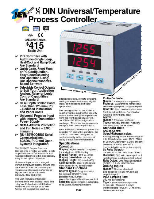
M A N U A L T R A N S F E R S W I T C H E SF R O MINSTALLATION AND OPERATING INSTRUCTIONSResidential Wattage RequirementsAppliance RunningWatts Add watts for startingFurnace blower, gas or fuel1/8 hp300 5001/8 hp500 7501/6 hp500 7501/4 hp600 10001/3 hp700 14001/2 hp875 2100Shallow well pump1/3 hp750 14001/2 hp1000 2350Sump pump1/3 hp800 13001/2 hp1050 2150Refrigerator or freezer 800 2300Garage door opener1/4 hp550 11001/3 hp750 1400Lights onbulb0 Radio 50-2000 Television 100-3000 Microwave oven 600-1500 0Coffee maker, typical 1750 0Toaster/toaster oven 1050-18500Portable heater 1100-15000Dehumidifier 650-800Electric blanket 400 0Clothes washer 1150 2300Clothes dryer, gas 700 1800Dishwashercool dry700 1400hot dry1450 1400Vacuum cleaner 800-1100 0Hair dryer 300-1500 0Iron 1200Warning:damage or personal injury by electrocution or fire. Installation must be Warning:switch are to be considered live unless both switches controlling theReliance Controls Corporation is not responsible for damage or injury caused by incorrect installation of this transfer switch.Member, National Electrical Manufacturers AssociationKey Components of the Reliance Transfer SwitchCircuit breakers. Each transfer switch circuit has a 15- or 20-amp push-to-reset circuit breaker that protects the branch circuit when the circuit selector is in the GEN position. In the LINE position, each branch circuit is protected by the breaker in the load center.Circuit selector switches. These switches allow you to select either GEN (generator) or LINE (utility) as the power source for the branch circuits that have been wired through the transfer switch. The OFF position is generally not used, as a switch in the OFF position removes that branch circuit from both utility and generator power.Handle ties. Handle ties are used for 240-volt circuits. They may be removed for 120-volt circuits. See page 6 for instructions on removing and adding handle ties.Power inlet (cord-connected models only). The power cord from the generator is plugged into this inlet. This is supplied separately for indoor models to encourage the use of a remote connection outdoors reducing the likelihood of running the generator indoors which is extremely dangerous (see page 7 for installation instructions). If this indoor model is installed outdoors, make sure it is protected from the outdoor elements.Power inlet filler plate . Models without the power inlet installed have a filler plate covering the hole in the wiring compartment cover (models shown on cover). This can be replaced with a power inlet (see Power inlet above).Wiring Compartment Cover. All models include a wiring compartment that can be used to hard-wire the unit to a remote power inlet box.Watt meters (select models only). These meters indicate the total load, in watts, on each side of the generator when the generator is supplying power as follows:The left meter measures the load on The right meter measures the load on A, B and C 6-circuit D, E and F 6-circuitA, B, C, and D 8-circuit E, F, G and H 8-circuitA, B, C, D and E 10-circuit F, G, H, I and J 10-circuitNote: The watt meters will register only if power is being used from the generator.Circuit breakers Circuit selector switchesWatt meters(select models only)Wiring CompartmentCoverHandle tiePower Inlet (not installed onindoor models).Figure 1Preparing for InstallationYou will need the following items:Electric drillScrewdriverWire cutters/stripperHammerFour anchors and screws4, 6, 8 or 10 yellow wire connectors (depending on the model)4 red wire connectors for the 20A and 30A hard-wire models4 blue wire connectors for the 50A hard-wire modelsThe following five steps generally apply to all transfer switch installations. For flush mounted units (model number begins with the letter "F"), please see the supplemental installation instructions packaged with each unit, as they will supercede some of the instructions shown here. For outdoor units (model number begins with the letter "R"), connect the wires from the unit to the main panel per these installation instructions. Please note the special conduit for the outdoor unit is included but not installed on the unit. Install the conduit supplied using acceptable practices for a raintight application.The transfer switch may be installed on either side of the load center.1. Turn off the main circuit breaker in the load center to ensure your2. Remove the cover of the load center.3. Locate and remove a knockout (ko)in the bottom of the load center(Figure 2). Use a 1/2" ko for 4-circuitmodels, a 3/4" ko for 6-circuitmodels, and a l" ko for 8-to 10-circuitmodels.4. Insert the wires extending from theend of the flexible conduit throughthe ko. Attach the conduit connectorsecurely with the locknut provided.5. Anchor the transfer switch to the wallusing the external feet. Do notattempt to bend the flexible conduitbeyond its structural capabilities .Wiring the Reliance Transfer Switch to the Load CenterDetermine which circuits will be used during an emergency. See the residential wattage requirement chart on the inside front cover of this manual. If a selected circuit is part of a multi-wire branch circuit, ensure the other branch circuit that shares the neutral is also connected to the transfer switch. The two circuits must be connected to opposing legs (phases) of the generator power and a handle tie must be installed on the switch handles so that both legs are transferred at the same time.Warning:overloading the neutral wire.branch circuits depends on the model of the transfer switch as follows:Model Max Available for multi-wire branch circuits 15114A, 30114A 4 None31404A, B or C, 20504B, 30504B 4 Circuits B and C.All 6-Circuit Models 6 Circuits C and D only on indoor models.Any two adjacent circuits on outdoor models(models with an "R" prefix).All 8-Circuit Models 8 Any two adjacent circuits.All 10-Circuit Models 10 Any two adjacent circuits.Balancing the LoadTo maximize the efficiency of your generator,divide appliance circuits and others requiringhigher wattage between the left and right sideof the transfer switch so that a usage balanceis achieved.For example, on a 6-circuit transfer switch,consider wiring the refrigerator to Switch Aand the furnace to Switch D (Figure 3).Figure 3Installing 120-volt CircuitsWarning:caps) must be installed on only those branch circuits with 20 amp branch circuit breakers. Transfer switch circuits with 15 amp breakers can be installed on 15 or Wire the most critical circuits first, starting with Switch A on the transfer switch. Let's assume that Switch A will be designated to supply power to the refrigerator.1. Turn off the refrigerator circuit breaker. Loosen the screw that secures the wire to thecircuit breaker. Disconnect the wire from the circuit breaker.2. On the transfer switch, find the black and red wires marked A.3. Feed the red wire to the selected breaker, in this case the refrigerator breaker.4. Cut the red wire A to a convenient length. Strip approximately 5/8" from the end of thewire. Connect the red wire to the refrigerator circuit breaker and retighten the screw. 5. Cut the black wire A to a convenient length for aligning with the wire removed from therefrigerator circuit breaker in step 1. Strip approximately 5/8" from the end of the wire. 6. Insert both wires (the wire removed from the circuit breaker in step 1 and the blackwire) into a yellow wire connector. Twist the connector tightly and push the wires back into the wiring compartment of the load center.This completes the installation of the transfer switch for your refrigerator.Repeat steps 1-6 for each of the remaining considering the following:• See the following section for 240-volt circuits and the removal of handle ties if 240-volt circuits are not required.• Remember to "balance the load"—dividing the appliances requiring higher wattage between the left and right sides of the transfer switch.• If you are installing model 15114A or 30114A, follow the same steps for B, C andD circuits, and proceed to the instructions for completing the installation on page8.Installing 240-volt CircuitsOn certain models, two adjacent circuit selector switches may be used for 240-volt operation. A handle tie is used to connect the two circuit selector switches for the following circuits:Models 15114A, 30114A None (these are for 120-volt use only) Models 31404A, B or C, 20504B, 30504B Circuits B and C.All 6-Circuit Models Circuits C and D only on indoor and flushmodels. Any two adjacent circuits on outdoormodels (Models with an "R" prefix)*.All 8-Circuit Models Any two adjacent circuits*All 10-Circuit Models Any two adjacent circuits**Note: Circuits used for multi-wire branch circuits are not available for 240-volt circuitsRemoving handle ties. If there are no 240-volt or multi-wire circuits in the transfer switch installation, handle-ties on the switches are not needed. To remove a handle tie, place the handle-tied switch in the GEN position. Loosen the two screws and remove the handle tie. Adding handle ties. If additional ties are needed to accommodate additional 240-voltor multi-wire circuits, they can be added to adjacent pairs of switches according to the table above.Warning:caps) must be installed on only those branch circuits with 20 amp branch circuitbreakers. Transfer switch circuits with 15 amp breakers can be installed on 15Installing 240-volt circuit(s)1. Locate the two red and two black wires for the circuits with the handle tie.2. Turn off the double-pole breaker in the load center.3. Loosen the screws that secure each wire to each circuit breaker. Disconnect the wiresfrom the circuit breakers.4. Feed the two red wires from the handle-tied switch(es) to the double-pole circuitbreaker.5. Cut the red wires to a convenient length. Strip 5/8" from the end of each wire. Connectthe two red wires to the double-pole circuit breaker.6. Cut the black wires to a length convenient for aligning with wires removed from thecircuit breaker. Strip 5/8" from the end of each wire.7. Insert one wire removed from the circuit breaker and one black wire into a yellow wireconnector. Twist to tighten and push the wires back into the wiring compartment of the load center. Do the same for the other wire removed from the circuit breaker and the other black wire from the transfer switch.Repeat steps 1-7 for the other double-pole circuits (8- and 10-circuit models only).For Indoor Surface Mount Models (those with no power inlet) or to hard-wire cord-connected Models (those with a suffix "A" in the Model number), continue to the next section entitled "Hard-wire Installation" to complete the installation.For all other models, skip to "Completing the installation" on page 8.Figure 5 Hard-wire Installation"Hard-wire" installation to a power inlet box located remotely from the transfer switch (Figure5) requires additional steps to complete the installation. The wire connections to the wires from the power inlet boxare made in the wiringcompartment of the transfer switch. Accessthe wiring compartmentby removing the wiring compartment cover (SeeFigure 1). This done byremoving the two screwslocated at the bottom ofthe front of the transferswitch. Replace thecover when installation is complete.Watt Meters. SomeModels are supplied with watt meters to measure the generator output. When connecting the transfer switch to either a power inlet or power inlet box, run the black wire lead going to the inlet through the hole in the current transformer (the small black doughnut-shaped device) attached to the left hand meter before connecting it to the power inlet or the wires from the power inlet box. Run the red wire lead through the hole in the current transformer attached to the right hand meter before connecting it to the power inlet or the wires from the power inlet box. No direct connection to the meter is necessary for the meters to function as describe on the bottom of page 2.Hard-wire Models. All of these Models have leads in the transfer switch wiring compartment that need to be connected to the incoming wires from the remote power inlet box. See Watt Meters above for Models ending with a suffix "C". Connect the wire leads in the transfer switch to the remote power inlet box using the following color key:the black wire to the power inlet X or Y terminal.the white wire to the power inlet neutral W terminal.the red wire to the power inlet X or Y terminal.the green wire to the power inlet ground G terminal.The incoming power from the generator may be supplied to any of the above models through the optional power inlet. This optional inlet enables a cord connection directly to the front of the transfer switch. Simply remove the plastic cover plate with the Reliance name embossed on it, install the appropriately sized power inlet and wire according to the inlet instructions using the same color key as used for the remote power inlet box. Inlet InstallationSuffix A models have a power inlet included. The inlet can be installed on the unit by removing the wiring compartment cover (described in the proceeding section) and the power inlet cover plate, installing the inlet with the enclosed screws onto the wiring compartment cover, and connecting the wire leads to the inlet as described in the instructions included with the inlet. See Watt Meters above before making the connections. Make sure the transfer switch is protected from the outdoor elements when installed outdoors.Completing the InstallationWhen you have wired all the load circuits in the transfer switch, only the white neutral wire and the green ground wire remain.1. Insert the white neutral wire into an unused opening in the neutral bar in the loadcenter and tighten the screw (Figure 4).2. Insert the green ground wire into an unused opening in the ground bar, if existing, andtighten the screw. If no ground bar exists, insert the green wire into an unused hole in the neutral bar and tighten the screw.3. Replace the cover to the load center.4 Fill in the chart on the transfer switch to identify your emergency circuits andcorresponding circuit numbers in the load center.5 Turn on all branch circuit breakers and the main breaker that were turned off forinstallation in the load center.6 Turn all switches on the transfer switch to the LINE position.Installation is now complete.Using your Reliance Transfer Switch and Your Portable Generator Warning:You want your generator to be ready when you need it. Therefore, it is important to perform the following steps at least once a month to keep the generator in peak running condition.• Start and run your generator under load regularly.• Keep the fuel tank filled with fresh fuel.It is not necessary to turn off any circuits in the load center when supplying generator power with the transfer switch, even when the utility power is operating normally. The double-throw action of these switches prevents feeding generator power to the utility and, conversely, prevents feeding utility power to the generator.Transferring from Utility Power to Generator Power1. Plug the female connector of the generator power cord into the power inlet box or thepower inlet on the transfer switch. All circuit selector switches on the transfer switch should be in the LINE or OFF position.2. Insert the male plug of the power cord into the outlet on the generator.3. Start the generator outdoors. Follow the procedures described in the generatorowner's manual furnished by the manufacturer of the generator.4. Select the circuits to be powered by the generator by moving the correspondingswitches on the transfer switch to the GEN position. Use only necessary household items when under generator power.5. Alternate use of larger loads (furnace motors, well pumps, refrigerators, etc.) tobalance the load. See "Balancing the load" on page 4. Do not exceed the maximum wattage of the transfer switch.6. Some circuits are limited by the transfer switch circuit breaker to a maximum of 15amps when switched to the GEN position. If you have switched on a circuit selector switch on such a 15-amp circuit to the GEN position that normally draws more than 15 amps, turn off some of the appliances on that circuit to avoid exceeding the 15-amp load for that circuit.7. Test your circuits by using the watt meters on the transfer switch or determine wattagefrom the nameplate on each appliance or motor.8. Models 15114A, 30114A, and all suffix "B" Models except the 8-circuit Models do nothave watt meters. See the note below for additional information on these models.9. Make a note of any excessive loads. These loads must be turned off duringgenerator operation.Transferring from Generator Power to Utility Power1. Return all circuit selector switches to the LINE position.2. Follow the procedures in the generator owner's manual to turn off the generator.3. Unplug the power cord.Notes on Models Without Watt MetersIf there are no watt meters for checking appliance or motor load, check the nameplate on each appliance or motor and note the load for each.The total running wattage for each of these models is as follows:Model 15114A 1875 wattsModel 30114A 3750 watts30A Models (see Maximum Input on cabinet label) 7500 watts50A Models (see Maximum Input on cabinet label) 12500 wattsDuring an emergency, the switches should be in the OFF or LINE position when a particular load is not needed. Failure to limit the total load to the total running wattage may cause the generator to stall or burn out the appliance motor.Model # / Configuration 15114A 30114A 20A6-Cir30A6-Cir50A6-Cir30A8-Cir50A8-Cir30A10-Cir50A10-CirMax. Watts 1875 3750 5000 7500 12500 7500 12500 7500 12500 Max. single-pole circuits 4 6 8 10Max. double-pole and multi-wire circuits 0 1 45# of handle ties provided n/a 1 2Max. combined loadsAmps @ 125 VAC 15 3040 60 100 60 100 60 100 Max. combined loadsAmps @ 250VAC n/a 20 30 50 30 50 30 50Max. load/circuit fromgenerator 15 amps 4-15 amps & 2-20 amps 6-15 amps & 2-20 amps6-15 amps & 4-20 ampsMax. load/circuit fromload center 20 ampsPower inlet, NEMA*configuration - CordConnected Models5-15 L5-30 L14-20 L14-30 CS6365 L14-30 CS6365 L14-30 CS6365 Minimumcordgauge 14 10 12 10 6 10 6 10 6 No. of conductors (wires) 3-wire 4-wire Conduit length 18"Conduit, trade-sizediameter1/2" 3/4" 1"Optional Power InletCatalog #PB15 PB31 PB20 PB30 PB50 PB30 PB50 PB30 PB50 Shipping weight 9 lbs. 10 lbs. 13 lbs.Dimensions (H x W x D) 7 1/2" x 7" x 4 1/2" 13 1/4"x 7"x 4"*National Electrical Manufacturer's Association Note: If your model is not listed here, pleaserefer to the supplemental installation instructionspackaged with that unit.Transfer Switch Parts List3Description Part#Circuit breaker, 15A 6291Circuit breaker, 20A 6292Wattmeter, 30A (3750 watts)6293Current Transformer (3750 6294Switch, 30A SPDT7801Power inlet, 20A6503Power inlet, 30A 6702Handle tie6295Power Inlet Filler Panel 6271Power Inlet BoxesIdeal for installations where the house electrical panel is locatedindoors. No need to run the power cord from the generator to thetransfer switch through a door or window. This weather-tight powerinlet box can be mounted on the exterior of the house. Run wiringthrough the wall from the inlet box to the transfer switch installationinside. The generator power cord may then be plugged into thepower inlet box. Catalog# Connector configuration Inlet description For use with modelsPB15 5-15 3-wire weather-tight male 15114APB20 L14-20 4-wireweather-tight male20216APB30 L14-30 4-wire weather-tight male All 30A ModelsPB31 L5-30 3-wire weather-tight male30114APB50 CS6364 4-wire weather-tight maleAll 50A Models Flush KitsHinged CoversPower CordsThese heavy duty cord sets are the connecting linkbetween the generator and the Reliance transfer switch orthe power inlet box. The 4-wire locking plug and connectormatch up with the power inlet on each Reliance transferswitch and with the inlet on the power inlet box. Mostportable generators suitable for 120/240 full-poweroperation are supplied with either a 20-amp or 30-amp, 4-wire locking receptacle that accepts the locking plug and connector on each end of the cord set.Watt Meter PanelKits for flush mounting all Pro/Tran® indoortransfer switches are available. Order KF6 for the four- and six-circuit models and KF10 for the eight- andten-circuit models.High-impact clear plastic covers protect from accidental con-tact with transfer switch. Order CK6 for the four- and six-circuit models and CK10 for the eight- and ten-circuit models.Watt Meter Panel WP7500 may replace the blank cover onany indoor suffix B Pro/Tan® model to provide importantinformation on the output from a 20A or 30A, 125/250VACgenerator. Accuracy is plus or minus 3%.Reliance Controls Corporation is pleased that you have made the decision to purchase this product. We have been manufacturing innovative, quality electrical controls for nearly 100 years. Our products are backed by one of thebest warranties in the industry.Reliance transfer switches areWarrantyEach Reliance transfer switch or accessory is guaranteed against mechanical or electrical failure dueto manufacturing defects for a period of 24 months following shipment from the factory. The manufacturer's responsibility during this warranty period is limited to repair or replacement, free of charge, of products proving defective under normal useor service when returned to the factory, transportationcharges prepaid. Guarantee is void on products that have been subjected to improper installation, misuse,alteration, abuse or unauthorized repair. The manufacturer makes no warranty with respect to the fitness of any goods for a user's particular applicationand assumes no responsibility for proper selection andinstallation of its products. This warranty is in lieu of allother warranties, expressed or implied, and limits themanufacturer's liability for damages to the cost of theproduct. This warranty gives you specific legal rights,and you may have other rights, which vary from stateto state.Reliance Controls Corporation / 2001 Young Court / Racine, Wl 53404Phone: (800) 634-6155 Fax: (262) 634-6436© Copyright 2000 Reliance 2/25/10。
欧诺克 DE2系列伺服驱动器 产品说明书

DE2系列伺服驱动器使用说明书DE 2 series servo driver instruction manual深圳市欧诺克科技有限公司DE2系列伺服驱动器型号说明DE2系列驱动器规格汇总表18~90VDC 增量式绝对值驱动器型号供电电压连续电流 Amps(Arms) 峰值电流 Amps(Arms)6S 反馈类型外形尺寸重量DE2PC-09003-OPEA 3A (2.1A ) 6A (4.2A )208*118*40mm0.7kg5A (3.5A ) 10A (7A )DE2PC-09005-OPEA DE2PC-09010-OPEA 25A (17A )10A (7A )DE2PC-09016-OPEA 16A (11A )48A (33A )DE2PC-09024-OPEA 24A (16A )50A (35A )DE2PC-09040-OPEA 40A (28A ) 80A (56A )DE2PC-09050-OPEA 50A (35A ) 100A (70A )DE2PC-09075-OPEA 75A (52A ) 150A (105A )245*148*59mm 1.65kg DE2PC-090100-OPEA100A (70A ) 200A (140A )DE2PC-090150-OPEA 150A (105A ) 250A (175A )DE2PC-18024-OPEA 18~180VDC24A (16A ) 50A (35A )208*118*40mm 0.7kg 50A (35A ) 100A (70A )245*148*59mm1.65kgDE2PC-18050-OPEA DE2PC-18075-OPEA 75A (52A ) 150A (105A )18~135VDC DE2PC-135100-OPEA 100A (70A ) 200A (140A )备注: 1.驱动器供电电压必须大于或者等于电机额定电压2.驱动器的额定电流必须大于或者等于电机的额定电流DE2PC-09012- OP E B系列DC/DE/DE2/BC/BC2/DH/BH制动单元B:带制动单元反馈E:光电增量式A/B 正交C:磁电增量式A/B 正交 A17:光电绝对值17bit C17:磁电绝对值17bit R:旋转变压器 H:数字霍尔 S:模拟量正余弦输入指令P:脉冲Hp:高速脉冲A:模拟量R:RS485 C:CANopen E:EtherCAT特殊功能OP:脉冲输出 OA:模拟量输出R:轮切 F:追剪 Z:攻丝机专用额定电流16:16Amps(11Arms) 50:50Amps(35Arms) 150:150Amps(105Arms)供电电压090:18-90VDC 180:18-180VDC 135:18-135VDC 220:220VAC 380:380VAC A:单相B:三相DE2系列端子定义DE2系列外形尺寸图LL 1H1H2H 3H4H WWJ3J4 J5 J6 J7 J8 SWJ1 & J11J10J2 & J9型号L L1W H H1H2H3H4DE2PC-09003A~50A 20819840118101/4-4.8192DE2PC-09075A~150A 24523559148 8034.54-5.0229DE2PC-18024A 20819840118101/4-4.8192DE2PC-18050A~75A 245235591488034.54-5.0229DE2PC-135100A1、产品简介:1.1概述DE2系列可编程智能伺服驱动器是一款通用、高性能、直流供电、结构紧凑的全数字伺服双驱动控制器。
Endress+Hauser H12012 PID控制器说明书
P-971⁄4DIN Universal/TemperatureߜPID Controller withAutotune–Single Loop,Heat/Cool and Ramp/Soak Are StandardߜQuick Code, Front Faceor PC Configuration–Easy Commissioning and Operation Using Our Optional Windows-Based SoftwareߜSelectable Control Outputsto Suit Your Application–Analog, Relay or Logic Control Capabilities Are StandardߜCase Depth Behind PanelLess Than 125 mm (5") – Reduced Installation and Panel CostsߜUniversal Process Inputwith Integral Transmitter Power SupplyߜNEMA-4X/IP66 Protectionand Full Noise + EMC ImmunityߜRS-485/MODBUS SerialCommunications –SCADA, PLC and Open Systems IntegrationCN3420 Series$415Basic UnitThe CN3420 Series ProcessController is a highly versatile, single loop controller in 1⁄4DIN format that has been designed to be exceptionally easy to set up and operate.Universal input and an integraltransmitter power supply ensure that the CN3420 has the capability to measure a wide range of process signals such as temperature,pressure,flow and level.The unit features enhancedperformance with analog, logic and relay control outputs, all fitted as standard, and an option to add further I/O capabilities such asSpecifications OperationDisplay:High intensity 7-segment, 2 x 4-digit red LED display. Display Range:-999 to +9999Display Resolution:±1 digit Display Height:12 mm (0.43")Configuration:User-defined via front panel or PC configuratorStandard FunctionsControl Types:Programmable for manual, ON/OFF, time proportioning, currentproportioning and heat/cool control Setpoints:Local, remote, 4 selectable,fixed value, ramping setpointNumber:4 ramp/soak segments Features:Guaranteed ramp/soak, self-seeking setpoint, program repeat Controls:Run, hold and stop from front panel switches. Run/hold or run/stop from digital input Alarms:Number:Two user-definedType:High/low process, high/low deviation, loop break alarmStandard BuildAnalog ControlOutput/Retransmission:Analog, configurable in the range of 4 to 20 mA. Max. load: 15 V (750 Ωat 20 mA); Accuracy: 0.25% of span;Dielectric: 500 Vdc from input(not isolated from dc pulse output)dc Pulse Output:18 Vdc at 20 mA; Min. load: 400 Ω;Dielectric:500 Vdc from input (not isolated from analog control output)Relay Output:One relay as standard (SPDT); 5 A @ 115/230 VacAnalog InputsNumber:One as standard; one optional 4 to 20 mA remote setpoint inputInput Sampling Rate:250 ms per channelType:Universally configurable to provide (Channel 1 only);thermocouple (TC), RTD, millivolt,current, dc voltageanalog retransmission and digital input, as needed to suit your application.The configuration of the CN3420 is achieved by moving the security switch and entering a simple code from the front panel keys or via our CN34-SW PC configuration package. There are no passwords,no input links, no complications.With NEMA-4X/IP66 front panel and superior RF immunity standard, the CN3420 has been designed to control reliably in the harshest of today’s industrial environments.ProgramIN STOCK FOR FAST DELIVERY!Input Impedance:mA: 100 ΩmV, V: >10M ΩLinearizer Functions:Programmable for standard inputs: TC types B, E, J, K, N, R, S, T or Pt100 RTDBroken Sensor Protection:Upscale drive on TC and RTD; Downscale drive on milliamps and voltageCold Junction Compensation:Automatic CJC incorporated as standard; Stability <0.05°C/°C change in ambient temperature Input Protection:Common mode isolation: >120 dB at 50/60 Hz with 300 Ωimbalance; Series mode rejection: >60 dB 50/60 HzTransmitter Power Supply:24 V, 30 mA max.Relay Output:SPDT: 5 A @ 115/230 Vac Digital Input:Type: Volt-freeMinimum pulse: 250 msMODBUS Serial Communications:Connections: RS-422/485, 2- or 4-wire Speed: 2.4 k or 9.6 k baud rate Protocol: MODBUS RTU slaveRemote Setpoint Input:4 to 20 mA dc, 100 Ωnominal input impedance.Preset to process variable engineering unitsAuxiliary Analog Output:Analog,configurable in the range of 4 to 20 mA.Max. load: 15 V (750Ωat 20 mA);Dielectric: 500 Vdc from inputPhysicalSize:96 W x 96 H x 122.5 mm D (3.78 x 3.78 x 4.82")Weight:520 g (1.1 lb) approx.ElectricalVoltage:85 to 265 Vac (50/60 Hz), 24 Vdc Power Consumption:<6 VA Power Interruption Protection:<60 ms/<3 cycles, no effect<60 ms/>3 cycles, instrument returns to operation after a controlled resetEnvironmentalOperating Limits:0 to 55°C (32 to 131°F);5 to 95% RH non-condensing Temperature Stability:<0.02% of reading or 2 µV/°C (1 µV/°F)Front Face:NEMA-4X (IP66), rear IP20EMCEmissions:Meets requirements of EN50081-2Immunity:Meets requirements of EN50082-2Electrical Safety:EN61010-1PAccuracy (% of reading)ThermocoupleSee Section A.GEQSS-14G-12CANADA www.omega.ca Laval(Quebec) 1-800-TC-OMEGA UNITED KINGDOM www. Manchester, England0800-488-488GERMANY www.omega.deDeckenpfronn, Germany************FRANCE www.omega.frGuyancourt, France088-466-342BENELUX www.omega.nl Amstelveen, NL 0800-099-33-44UNITED STATES 1-800-TC-OMEGA Stamford, CT.CZECH REPUBLIC www.omegaeng.cz Karviná, Czech Republic596-311-899TemperatureCalibrators, Connectors, General Test and MeasurementInstruments, Glass Bulb Thermometers, Handheld Instruments for Temperature Measurement, Ice Point References,Indicating Labels, Crayons, Cements and Lacquers, Infrared Temperature Measurement Instruments, Recorders Relative Humidity Measurement Instruments, RTD Probes, Elements and Assemblies, Temperature & Process Meters, Timers and Counters, Temperature and Process Controllers and Power Switching Devices, Thermistor Elements, Probes andAssemblies,Thermocouples Thermowells and Head and Well Assemblies, Transmitters, WirePressure, Strain and ForceDisplacement Transducers, Dynamic Measurement Force Sensors, Instrumentation for Pressure and Strain Measurements, Load Cells, Pressure Gauges, PressureReference Section, Pressure Switches, Pressure Transducers, Proximity Transducers, Regulators,Strain Gages, Torque Transducers, ValvespH and ConductivityConductivity Instrumentation, Dissolved OxygenInstrumentation, Environmental Instrumentation, pH Electrodes and Instruments, Water and Soil Analysis InstrumentationHeatersBand Heaters, Cartridge Heaters, Circulation Heaters, Comfort Heaters, Controllers, Meters and SwitchingDevices, Flexible Heaters, General Test and Measurement Instruments, Heater Hook-up Wire, Heating Cable Systems, Immersion Heaters, Process Air and Duct, Heaters, Radiant Heaters, Strip Heaters, Tubular HeatersFlow and LevelAir Velocity Indicators, Doppler Flowmeters, LevelMeasurement, Magnetic Flowmeters, Mass Flowmeters,Pitot Tubes, Pumps, Rotameters, Turbine and Paddle Wheel Flowmeters, Ultrasonic Flowmeters, Valves, Variable Area Flowmeters, Vortex Shedding FlowmetersData AcquisitionAuto-Dialers and Alarm Monitoring Systems, Communication Products and Converters, Data Acquisition and Analysis Software, Data LoggersPlug-in Cards, Signal Conditioners, USB, RS232, RS485 and Parallel Port Data Acquisition Systems, Wireless Transmitters and Receivers。
RH3操作说明
I. 综 合 描 述
图象识别
0.36秒/件
0.45秒/件
0.6秒/件
0.7秒/件
(*1)在NC数据中规定插入速度如果要自动转换到另外一档须要满足下面条件的规定: ——与XY移动工作台的距离 ——插入元件的备用料站号码
(*2)对于0.36秒/件 和0.45秒/件 的初始插入速度为0.6秒/件 .
适合的PC板尺寸 最大料仓装载容量 插入间距 插入方向 工作温度 气动控制部
Ⅱ操 作
2) MACHINE CHECK菜单简介
MACHINE CHECK
F1 NC AXIS JOG CHECK
F2
NC AXIS MOVE CHECK
F1 MOVE
F3
NC DATA TEACHING
F5
RECOGNITION SCREEN
F6
SEQUENCE TIMER
F1 YES F2 NO
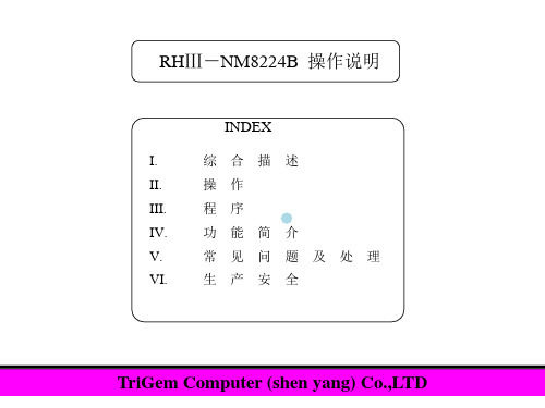
RHⅢ-NM8224B 操作说明
INDEX
I.
综合描述
II.
操作
III.
程序
IV.
功能简介
V.
常见问题及处理
VI.
生产安全
TriGem Computer (shen yang) Co.,LTD
I.
综合描述
设备构造简介:
I.
综合描述
急停开关 集尘箱
Head drive Unloader
后控制台
自动补正部分 主控制面板 急停开关 灯塔
X-Y轴:绝对指令。 Z轴:部件所用料仓号指令。 0.01mm/1脉冲
3.5英寸软盘。 在线数据通过RS232C输入/输出。 手动数据输入是通过字符键入完成。
打印机
深圳朗仁科技XTOOL PS2 Heavy Duty柴油说明书
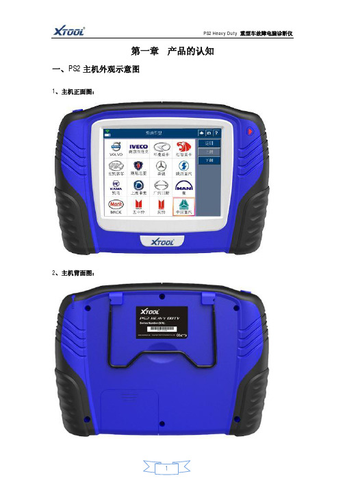
主机信息键,点击该键将显示该主机相关信息(包括软、硬
件版本,发布日期和产品序列号等)。
帮助键,点击该键将显示帮助信息、技术资料等。
无线蓝牙信号提示。
主机电池电量提示。
4、子菜单功能键说明:
功能键功能说明
抓图键,点击该键将对屏幕进行抓图,所抓图存
放在主机SD
卡中“Snapshot”文件夹。
返回键,点击该键将以当前界面为基础返回到上一界面。
下翻键,点击该键将以当前界面为基础下翻到下一界面。
键即可显示主机软、硬件版本,发布日期和产品序列号信息,如下图所示。
▼
2、PS2主机的设置:
在主界面下方点击
语言设置菜单,进入该菜单可进行多语言切换。
屏幕校准菜单,进入该菜单可进行触摸屏校准。
亮度调整菜单,进入该菜单可进行显示屏亮度调整。
蜂鸣器设置菜单,进入该菜单可进行蜂鸣器的开、关设置。
公、英制切换菜单,进入该菜单可进行公、英制切换。
显示设置菜单,进入该菜单可进行主题选择和控制按钮的位置设置。
用户信息菜单,进入该菜单可输入用户信息。
USB连接设置菜单,进入该菜单可设置主机与PC进行连接通讯,进行数据同步。
联机诊断设置菜单,进入该菜单可设置主机进行有线诊断或无线诊断设置。
h系列伺服驱动器使用手册
h系列伺服驱动器使用手册摘要:I.引言- 简述H 系列伺服驱动器的背景和应用领域II.产品概述- 介绍H 系列伺服驱动器的型号和特点- 说明伺服驱动器的工作原理和基本构成III.安装与接线- 指导用户进行H 系列伺服驱动器的安装- 详细说明接线步骤和注意事项IV.操作与调试- 介绍H 系列伺服驱动器的操作方法- 指导用户进行调试和故障排查V.维护与保养- 说明H 系列伺服驱动器的维护方法和保养周期- 强调安全操作和设备维护的重要性VI.附录- 提供相关技术参数和联系方式正文:H 系列伺服驱动器使用手册H 系列伺服驱动器是一款高性能、高精度的驱动设备,广泛应用于工业生产领域。
本手册将为您介绍H 系列伺服驱动器的使用方法、安装技巧和维护保养知识,帮助您充分发挥设备性能,确保设备安全可靠运行。
一、产品概述H 系列伺服驱动器是公司生产的一款具有先进技术和卓越性能的驱动设备,具有以下特点:1.型号齐全:H 系列伺服驱动器包括多种型号,适用于不同功率和转矩需求的场合。
2.高精度:采用高分辨率编码器,实现精确的位置控制和速度控制。
3.高响应:快速响应指令,提高生产效率。
4.高可靠性:采用先进的技术设计和严格的质量控制,确保设备运行稳定可靠。
二、安装与接线1.安装环境:H 系列伺服驱动器应安装在通风、干燥、无腐蚀性气体的环境中,避免阳光直射和潮湿。
2.安装步骤:a.确定安装位置,确保地面平整、坚实。
b.将驱动器安装在支架上,用螺丝固定。
c.连接电源,注意电压和频率符合设备要求。
d.安装电机,将电机与驱动器用联轴器连接。
e.安装编码器,注意接线正确。
2.接线注意事项:a.使用规定的电缆和接线端子。
b.接线前,请仔细阅读接线图,确保接线正确。
c.接线时,请确保接线端子紧密连接,防止松动。
d.接线后,请检查接线是否牢固,防止因松动导致设备故障。
三、操作与调试1.开机准备:确保电源、电机、编码器接线正确后,打开电源开关。
Endurance Equipment EFP1.5H 消防泵用户手册说明书

USING YOUR FIRE PUMP
Whether you are washing down a tennis court or preparing for an approaching fire, the same basic procedures of fire pump operation apply:
2. Attach intake hose to pump. Take female cam lock on end of intake hose and clamp onto male cam lock that is now attached to the pump. 3. Attach the foot valve strainer to opposite end of intake hose. 4. Drop strainer end of intake hose into water source.
Gasoline Fire Pump 40/1.5 70/230 (100psi) 8/26 13.5/477 65 Forced Air cooled, 4-stroke OHV 6.5/3600 3.6/1 Unleaded gasoline Recoil 25/55 520x385x470 / 20.5x15x18.5 50’ Fire Hose, Fog/Stream Nozzle, 8’ Intake Hose with Strainer & Camlock Couplers
STORAGE
Proper storage of your fire pump system is essential to ensure that it is ready for the next use.
