NRLM223M350V22X30F中文资料
22 寸宽屏液晶显示器HW222 HW223 用戶手册
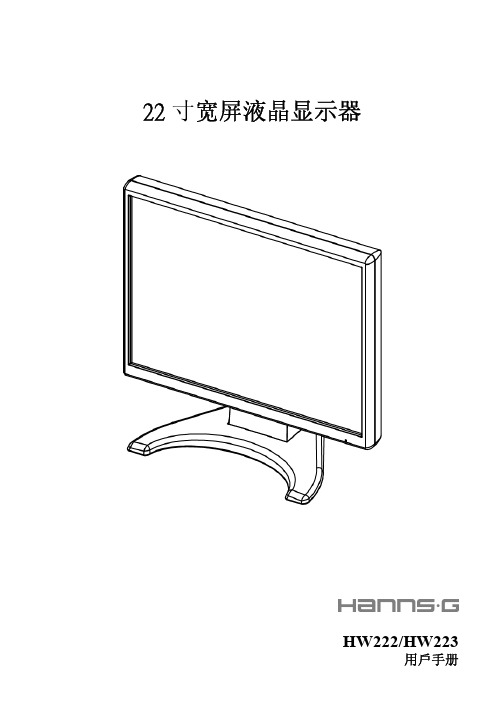
22寸宽屏液晶显示器HW222/HW223用戶手册用户说明书在操作显示器前请全部阅读此说明书,说明书应保留好,便于供将来参考用。
FCC B 类射频干扰声明经测试,本设备符合 FCC 规则第 15 部分对“B 类”数字设备的限制规定。
这些限制旨在提供合理的保护措施,以防该设备在住宅区安装时产生有害干扰。
本设备产生、使用并辐射射频能量,如果未遵照说明进行安装和使用,可能会对无线电通信产生干扰。
但也不能保证在特定的安装中不会产生干扰的问题。
如果本设备确实对无线电或电视接收造成干扰(可以通过开关设备来确定),建议用户采取以下一种或多种措施排除干扰:重新调整接收天线的方向或位置。
增大本设备与接收器的间距。
将设备电源连接到不同于接收器所连接到的电路的电源插座上。
咨询经销商或有经验的无线电/电视机技术人员以获取帮助。
本设备符合 FCC 规则第 15 部分的规定。
操作应符合以下两个条件:(1) 本设备不会造成有害干扰,并且(2) 本设备一定能够承受接收到的所有干扰,包括可能会造成意外操作的干扰。
加拿大本 B 类数字设备符合 Canadian Interference-Causing Equipment Regulations(加拿大设备引起干扰法规)的所有要求。
本设备符合电磁兼容性方面的 EMC 法令 89/336/EEC 的规定以及低压法令方面的73/23/EEC 和 93/68/EEC 规定。
电源插座应靠近设备并可以够到。
用户说明书Congratulations!The display you have just purchased carries the TCO’03Displays label. This means that your display is designed,manufactured and tested according to some of the strictestquality and environmental requirements in the world. This makesfor a high performance product, designed with the user in focusthat also minimizes the impact on our natural environment.Some of the features of the TCO’03 Display requirements:Ergonomics• Good visual ergonomics and image quality in order to improve the working environment for the user and to reduce sight and strain problems. Important parameters are luminance, contrast, resolution, reflectance, colour rendition and image stability.Energy• Energy-saving mode after a certain time – beneficial both for the user and the environment• Electrical safetyEmissions• Electromagnetic fields• Noise emissionsEcology• The product must be prepared for recycling and the manufacturer must have a certified environmental management system such as EMAS or ISO 14 001• Restrictions onchlorinated and brominated flame retardants and polymersheavy metals such as cadmium, mercury and lead.The requirements included in this label have been developed by TCO Development in cooperation with scientists, experts, users as well as manufacturers all over the world. Since the end of the 1980s TCO has been involved in influencing the development of IT equipment in a more user-friendly direction. Our labelling system started with displays in 1992 and is now requested by users and IT-manufacturers all over the world.For more information, please visit用户说明书回收信息我们,Hanns.G 极为重视环境保护战略,深信:通过在工业技术设备寿命结束时进行适当的处理和回收可以更好地保护我们的地球这些设备包含有可回收材料,可以将这些材料重新分解处理后用到新的产品中。
RE22R2AMR产品数据手册说明书

RE22R2AMR.T h e i n f o r m a t i o n p r o v i d e d i n t h i s d o c u m e n t a t i o n c o n t a i n s g e n e r a l d e s c r i p t i o n s a n d /o r t e c h n i c a l c h a r a c t e r i s t i c s o f t h e p e r f o r m a n c e o f t h e p r o d u c t s c o n t a i n e d h e r e i n .T h i s d o c u m e n t a t i o n i s n o t i n t e n d e d a s a s u b s t i t u t e f o r a n d i s n o t t o b e u s e d f o r d e t e r m i n i n g s u i t a b i l i t y o r r e l i a b i l i t y o f t h e s e p r o d u c t s f o r s p e c i f i c u s e r a p p l i c a t i o n s .I t i s t h e d u t y o f a n y s u c h u s e r o r i n t e g r a t o r t o p e r f o r m t h e a p p r o p r i a t e a n d c o m p l e t e r i s k a n a l y s i s , e v a l u a t i o n a n d t e s t i n g o f t h e p r o d u c t s w i t h r e s p e c t t o t h e r e l e v a n t s p e c i f i c a p p l i c a t i o n o r u s e t h e r e o f .N e i t h e r S c h n e i d e r E l e c t r i c I n d u s t r i e s S A S n o r a n y o f i t s a f f i l i a t e s o r s u b s i d i a r i e s s h a l l b e r e s p o n s i b l e o r l i a b l e f o r m i s u s e o f t h e i n f o r m a t i o n c o n t a i n e d h e r e i n .Product data sheetCharacteristicsRE22R2AMROn-delay Timing Relay - 0.05s…300h - 24…240V AC/DC - 2C/OMainRange of product Zelio TimeProduct or component typeModular timing relay Discrete output type Relay Device short name RE22Nominal output current8 AComplementaryContacts type and composition 1 C/O timed or instantaneous contact, cadmium free 1 C/O timed contact, cadmium free Time delay type A AwTime delay range0.3...3 s 1...10 s 0.05...1 s 3...30 s 10...100 s 30...300 s 3...30 min 30...300 min 3...30 h 30...300 hControl typeExternal potentiometer Diagnostic button Rotary knob[Us] rated supply voltage 24...240 V AC/DC at 50/60 Hz Release input voltage <= 2.4 V Voltage range 0.85...1.1 Us Supply frequency 50...60 Hz (+/- 5 %)Connections - terminalsScrew terminals : 2 x 0.2...2 x 1.5 mm², AWG 24...AWG 16 flexible cable with ca-ble endScrew terminals : 1 x 0.2...1 x 2.5 mm², AWG 24...AWG 14 flexible cable with ca-ble endScrew terminals : 2 x 0.5...2 x 2.5 mm², AWG 20...AWG 14 solid cable without cable endScrew terminals : 1 x 0.5...1 x 3.3 mm², AWG 20...AWG 12 solid cable without cable endTightening torque 0.6...1 N.m conforming to IEC 60947-1Housing material Self-extinguishingRepeat accuracy +/- 0.5 % conforming to IEC 61812-1Temperature drift +/- 0.05 %/°C Voltage drift+/- 0.2 %/VSetting accuracy of time delay +/- 10 % of full scale at 25 °C conforming to IEC 61812-1Control signal pulse width 30 ms100 ms (with load in parallel)Insulation resistance 100 MOhm at 500 V DC conforming to IEC 60664-1Recovery time120 ms (on de-energisation)Immunity to microbreaks <= 10 ms Power consumption in VA3 VA at 240 V ACPower consumption in W 1.5 W at 240 V DCSwitching capacity in VA2000 VAMinimum switching current10 mA 5 V DCMaximum switching current8 AMaximum switching voltage250 V ACElectrical durability100000 cycles for 2 A at 24 V DC-1100000 cycles for 8 A at 250 V AC-1Mechanical durability10000000 cyclesRated impulse withstand voltage 5 kV for 1.2...50 µs conforming to IEC 60664-1Power on delay< 100 msCreepage distance 4 kV/3 conforming to IEC 60664-1Overvoltage category III conforming to IEC 60664-1Mounting position Any positionMounting support35 mm DIN rail conforming to EN/IEC 60715Status LED Yellow LED (slow flashing) for timing in progress and output relay energisedYellow LED (fast flashing) for timing in progress and output relay de-energisedYellow LED (steady) for output relay energisedGreen LED backlight (steady) for dial pointer indicationProduct weight0.105 kgEnvironmentDielectric strength 2.5 kV for 1 mA/1 minute at 50 Hz between relay output and power supply withbasic insulation conforming to IEC 61812-1Standards IEC 61812-1UL 508Directives2004/108/EC - electromagnetic compatibility2006/95/EC - low voltage directiveProduct certifications CCCCECSAGLULRCMEACChina RoHSAmbient air temperature for operation-20...60 °CAmbient air temperature for storage-40...70 °CIP degree of protection IP50 (front panel) conforming to IEC 60529IP20 (terminals) conforming to IEC 60529IP40 (housing) conforming to IEC 60529Pollution degree 3 conforming to IEC 60664-1Vibration resistance20 m/s² (f = 10...150 Hz) conforming to IEC 60068-2-6Shock resistance 5 gn (in operation) (duration = 11 ms) conforming to IEC 60068-2-2715 gn (not operating) (duration = 11 ms) conforming to IEC 60068-2-27 Relative humidity95 % at 25...55 °CElectromagnetic compatibility Immunity to microbreaks and voltage drops (test level: 100 % - 20 ms) conform-ing to IEC 61000-4-11Immunity to microbreaks and voltage drops (test level: 30 % - 500 ms) conform-ing to IEC 61000-4-11Fast transient bursts (test level: 2 kV, level 3 - direct contact) conforming to IEC61000-4-4Conducted RF disturbances (test level: 10 V, level 3 - 0.15...80 MHz) conformingto IEC 61000-4-6Radiated radio-frequency electromagnetic field immunity test (test level: 10 V/m,level 3 - 80 MHz...1 GHz) conforming to IEC 61000-4-3Electrostatic discharge (test level: 8 kV, level 3 - air discharge) conforming to IEC61000-4-2Electrostatic discharge (test level: 6 kV, level 3 - contact discharge) conforming toIEC 61000-4-2Surge immunity test (test level: 2 kV, level 3 - common mode) conforming to IEC61000-4-5Surge immunity test (test level: 1 kV, level 3 - differential mode) conforming toIEC 61000-4-5Fast transients immunity test (test level: 1 kV, level 3 - capacitive connecting clip)conforming to IEC 61000-4-4Product data sheetRE22R2AMR Dimensions DrawingsDimensionsProduct data sheetRE22R2AMR Connections and SchemaWiring DiagramProduct data sheetRE22R2AMRTechnical DescriptionFunction A: Power On-DelayDescriptionOn energisation of power supply, the timing period T starts. After timing, the output(s) R close(s).The second output (R2) can be either timed (when set to "TIMED") or instantaneous (when set to "INST").Function: 1 OutputFunction: 2 OutputsFunction Aw : Power On-Delay With Retrigger / Restart ControlDescriptionOn energisation of power supply, the timing period T starts.At the end of the timing period T, the output(s) R close(s).Energization of Y1 makes the output(s) R open(s).Deenergization of Y1 restarts timing period T.At the end of timing period T, the output(s) R close(s).The second output (R2) can be either timed (when set to "TIMED") or instantaneous (when set to "INST")Function: 1 OutputFunction: 2 OutputsLegendRelay de-energisedRelay energisedOutput openOutput closedUSupply-TTiming period-R1/2 timed outputsR2-R2The second output is instantaneous if the right position is selected inst.-Retrigger / Restart controlY1-RE22R2AMR.。
三星2232MW用户手册

2
清洁
安全说明
请将加热装置尽量放置在远离电源线或本产品的地方。 • 否则可能导致触电或起火。
请勿将其安装在书柜或壁橱等通风不良的地方。 • 否则可能因产品内部温度升高而导致起火。
请小心轻放显示器。 • 否则可能会损坏显示器。
要断开设备的电源,必须将插头从电源插座拔出,因此电源插 头应易于操作。 • 这可能导致电击或火灾。
仅可使用本公司提供的电源线。请勿使用其它产品随附的电源 线。 • 否则可能导致起火或触电。
如果要在多尘、高温或低温、湿度高或曝露于化学物质中的环境安装显 示器,以及在需要 24 小时不间断运作的机场或火车站等地方安装显示 器,请务必与授权的服务中心联系。 否则,显示器可能会严重受损。
清洁布
HDMI 缆线
DVI 至 HDMI 缆线
耳塞/耳机
RCA 缆线
电视天线缆线
组合缆线
RCA 至立体声(适用于 PC) 缆线
S-VIDEO 缆线
10
介绍
显示器 正面
SOURCE 激活一个高亮显示的菜单项。 从 PC 模式切换到视频模式。 仅在有外部设备同时连接到显示器时才可以更改输入源。 要转换屏幕模式: [PC] → [DVI] → [电视] → [AV] → [S-Video] → [分量输出]→ [HDMI] >> 单击此处观看动画剪辑 MENU 打开 OSD 菜单。也用于退出 OSD 菜单或回到上一菜单。 - VOL + 在菜单项之间水平移动或调整选定的菜单值。还可以调整音量。
如果使用室外天线,则天线和附近电线之间应留有足够的距 离,以避免因天线被强风刮倒而彼此发生接触。 • 翻倒的天线可能会导致人身伤害或电击。
LM331中文资料 中文手册 芯片中文资料 芯片中文手册

电压-频率变换器LM331LM331是美国NS公司生产的性能价格比较高的集成芯片。
LM331可用作精密的频率电压(F/V)转换器、A/D转换器、线性频率调制解调、长时间积分器以及其他相关的器件。
LM331为双列直插式8脚芯片,其引脚如图3所示。
LM331内部有(1)输入比较电路、(2)定时比较电路、(3)R-S触发电路、(4)复零晶体管、(5)输出驱动管、(6)能隙基准电路、(7)精密电流源电路、(8)电流开关、(9)输出保护点路等部分。
输出管采用集电极开路形式,因此可以通过选择逻辑电流和外接电阻,灵活改变输出脉冲的逻辑电平,从而适应TTL、DTL和CMOS 等不同的逻辑电路。
此外,LM331可采用单/双电源供电,电压范围为4~40V,输出也高达40V。
引脚1(PIN1)为电流源输出端,在f0(PIN3)输出逻辑低电平时,电流源IR输出对电容CL充电。
引脚2(PIN2)为增益调整,改变RS的值可调节电路转换增益的大小。
引脚3(PIN3)为频率输出端,为逻辑低电平,脉冲宽度由Rt和Ct决定。
引脚4(PIN4)为电源地。
引脚5(PIN5)为定时比较器正相输入端。
引脚6(PIN6)为输入比较器反相输入端。
引脚7(PIN7)为输入比较器正相输入端。
引脚8(PIN8)为电源正端。
LM331频率电压转换器V/F变换和F/V变换采用集成块LM331,LM331是美国NS公司生产的性能价格比较高的集成芯片,可用作精密频率电压转换器用。
LM331采用了新的温度补偿能隙基准电路,在整个工作温度范围内和低到4.0V电源电压下都有极高的精度。
同时它动态范围宽,可达100dB;线性度好,最大非线性失真小于0.01%,工作频率低到0.1Hz时尚有较好的线性;变换精度高,数字分辨率可达12位;外接电路简单,只需接入几个外部元件就可方便构成V/F或F/V等变换电路,并且容易保证转换精度。
图2是由LM331组成的电压频率变换电路,LM331内部由输入比较器、定时比较器、R-S触发器、输出驱动、复零晶体管、能隙基准电路和电流开关等部分组成。
开关电源磁芯参数

.开关电源磁芯参数MnZn功率铁氧体EPC 功率磁芯特点:具有热阻小、衰耗小、功率大、工作频率宽、重量轻、结构合理、易表面贴装、屏蔽效果好等优点,但散热性能稍差。
用途:广泛应用于体积小而功率大且有屏蔽和电磁兼容要求的变压器,如精密仪器、程控交换机模块电源、导航设备等。
EPC 型功率磁芯尺寸规格磁芯型号尺寸 Dimensions(mm)Type A B C D Emin F G HminEPC10/810.20 ±0.20 4.05 ±0.30 3.40 ±0.20 5.00 ±0.207.60 2.65 ±0.20 1.90 ±0.20 5.30EPC13/1313.30 ±0.30 6.60 ±0.30 4.60 ±0.20 5.60 ±0.2010.50 4.50 ±0.30 2.05 ±0.208.30EPC17/1717.60 ±0.508.55 ±0.30 6.00 ±0.307.70 ±0.3014.30 6.05 ±0.30 2.80 ±0.2011.50EPC19/2019.60 ±0.509.75 ±0.30 6.00 ±0.308.50 ±0.3015.807.25 ±0.30 2.50 ±0.2013.10EPC25/2525.10 ±0.5012.50 ±0.308.00 ±0.3011.50 ±0.3020.659.00 ±0.30 4.00 ±0.2017.00EPC27/3227.10 ±0.5016.00 ±0.308.00 ±0.3013.00 ±0.3021.6012.00 ±0.30 4.00 ±0.2018.50EPC30/3530.10 ±0.5017.50 ±0.308.00 ±0.3015.00 ±0.3023.6013.00 ±0.30 4.00 ±0.2019.50EPC39/3939.00 ±0.5019.60 ±0.3015.60 ±0.3018.00 ±0.3030.7014.00 ±0.3010.00 ±0.3024.50EPC42/4442.40 ±1.0022.00 ±0.3015.00 ±0.4017.00 ±0.3033.5016.00 ±0.307.40 ±0.3026.50. EPC46/4946.00 ±1.0024.80 ±0.3019.50 ±0.4020.80 ±0.4035.7018.40 ±0.4011.90 ±0.3028.40EPC46.5/4446.50 ±1.0022.30 ±0.3019.40 ±0.4021.00 ±0.4036.9015.80 ±0.4012.00 ±0.3029.40EPC54/5454.50 ±1.2027.20 ±0.3021.50 ±0.4026.50 ±0.4043.0019.30 ±0.4014.00 ±0.3034.30EPC 功率磁芯电气特性及有效参数有效参数 Effective parameters 磁芯型号材质AL(nH/N2)C1Le Ae Ve重量功耗约设计功率( W)Type Material±25%(mm-1)(mm)(mm2)(mm3)(g/PRS)(W/PRS,max)1KHz/0.25v EPC10/8TP4950 1.9017.89.39167 1.10.133 EPC13/13TP4830 2.4530.612.5382 2.10.246 EPC17/17TP41150 1.7640.222.8917 4.50.5213 EPC19/20TP4900 2.0346.122.71047 5.30.6115 EPC25/25TP41550 1.2859.246.4274713.0 1.5040 EPC27/32TP41550 1.3473.154.6399120.0 2.3060 EPC30/35TP41500 1.3481.661497723.0 2.6570 EPC39/39TP442500.53901691521073.08.40220 EPC42/44TP428000.56951691605578.49.02235 EPC46/49TP441000.49111.222725242122.414.08360 EPC46.5/44TP448000.4410122923129125.014.38370 EPC54/54TP460000.39130.833643949200.023.00600注:AL 值测试条件为1KHz,0.25v,100Ts,25 ±3℃. Pc值测试条件为 100KHz,200mT,100 ℃EE、 EEL 、EF 型功率磁芯.特点:引线空间大,绕制接线方便。
FTM-350 中文说明书

[SET](设置模式)键
按此键可进入设置模式。
[DIAL] 旋钮
旋转该旋钮可以选择左侧 接收机的操作频率 (或存储信道)。 按住该旋钮一秒钟,能够以每次 1 MHz 的步 进调整 VFO 频率。 当左侧 接收机设置为“主”频段时,按一下 该旋钮即可激活频谱功能。 当左侧 接收机设置为“次”频段时,按一下 该旋钮即可将左侧 接收机切换至“主”频段。
[DIAL] 旋钮
旋转该旋钮可以选择右侧 接收机的操作频率 (或存储信道)。 按住该旋钮一秒钟,能够以每次 1 MHz 的步 进调整 VFO 频率。 当右侧 接收机设置为“主”频段时,按一下 该旋钮即可激活频谱功能。 当右侧 接收机设置为“次”频段时,按一下 该旋钮即可将右侧 接收机切换至“主”频段。
[PTT] 键
按下该键可进行发射。
麦克风
[B](频段)键
按下该键可更改主频段的操作频段。 可用频段包括 : 左频段 :调幅广播、调频广播、144 MHz 频段、
430 MHz 频段和音频线路输入 右频段 :144 MHz 频段和 430 MHz 频段 你可以通过设置模式项“B05 :RX EXPANSION” 调用增加的操作频段。见 35 页。
前面板的控制按钮与开关
[FWD]/[BCK](翻页)键
通过这两个键可以方便地选择操作功能页面。 可用的页面包括:“电台”页面、“定时器”页面、 “气压 / 海拔”页面、“导航”页面※ 以及“GPS 状态”页面※。 ※ :所需选购的“FGPS-1”GPS 设备。 按住这些键可以在双频接收功能的“开”和“关” 之间进行切换。
[F](功能)键
按该键可更改 [SMART FUNCTION] 键的当前 功能。
DIAL 照明 [VOL] 旋钮
NRLM222M35V22X30F中文资料
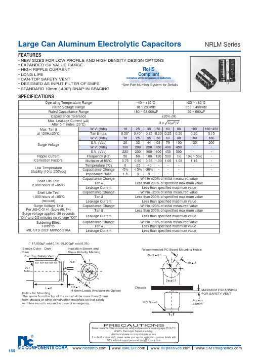
Large Can Aluminum Electrolytic CapacitorsFEATURES• NEW SIZES FOR LOW PROFILE AND HIGH DENSITY DESIGN OPTIONS • EXPANDED CV VALUE RANGE• HIGH RIPPLE CURRENT• LONG LIFE • CAN-TOP SAFETY VENT• DESIGNED AS INPUT FILTER OF SMPS • STANDARD 10mm (.400") SNAP-IN SPACING NRLM SeriesSPECIFICATIONS(* 47,000µF add 0.14, 68,000µF add 0.35.)Notice for MountingThe space from the top of the can shall be more than (3mm) from chassis or other construction materials so that safety vent has room to expand in case of emer g en c y.Sleeve Color: DarkBlueCan Top Safety VentInsulation Sleeve and Minus Polarity Marking(4.0mm Leads Available As Option)D+1Max.L ± 26.3 ± 10.810(-)(+)MAXIMUM EX P AN S IONFOR SAFETY VENT Approx. 3.0mmRecommended PC Board Mounting Holes:10 ± .1∅= 2 ± 0.1D ∅ ± 0.5ChassisPC BoardPRECAUTIONSPlease review the notes on correct use, safety and precautions found on pages T10 & T11of NIC’s Electrolytic Capacitor catalog . Operating Temperature Range-40 ~ +85°C-25 ~ +85°C Rated Voltage Range 16 ~ 250Vdc 350 ~ 450Vdc Rated Capacitance Range 180 ~ 68,000µF56 ~ 680µFCapacitance Tolerance ±20% (M)Max. Leakage Current (µA)After 5 minutes (20°C)3 x C(µF)VMax. Tan δat 120Hz/20°C W.V. (Vdc)162535506380100160~450Tan δ max.0.50*0.40*0.350.300.250.200.200.15Surge VoltageW.V. (Vdc)162535506380100160S.V. (Vdc)2032446379100125200W.V. (Vdc)180200250350400450--S.V. (Vdc)220250300400450500--Ripple CurrentCorrection Factors Frequency (Hz)50601001205001K 10K ~ 50K -Multiplier at 85°C0.750.800.95 1.00 1.05 1.08 1.15-Low TemperatureStability (10 to 250Vdc)Temperature (°C)0-25-40-----Capacitance Change-5%-15%-30%-----Impedance Ratio 1.539-----Load Life Test2,000 hours at +85°CCapacitance ChangeWithin ±20% of initial measured value Tan δLess than 200% of specifi ed maximum valueLeakage Current Less than specifi ed maximum value Shelf Life Test1,000 hours at +85°C (no load)Capacitance Change Within ±20% of initial measured value Tan δLess than 200% of specifi ed maximum valueLeakage Current Less than specifi ed maximum value Surge Voltage Test Per JIS-C-5141 (table #6, #4)Surge voltage applied: 30 seconds"On" and 5.5 minutes no voltage "Off"Capacitance Change Within ±20% of initial measured value Tan δLess than 200% of specifi ed maximum valueLeakage Current Less than specifi ed maximum value Soldering EffectRefer to MIL-STD-202F Method 210A Capacitance Change Within ±10% of initial measured valueTan δLess than specifi ed maximum value Leakage CurrentLess than specifi ed maximum valueRoHS Compliantincludes all homogeneous materials*See Part Number System for DetailsLarge Can Aluminum Electrolytic CapacitorsNRLM SeriesNRLM 222 M 50V 20X25 FRoHS compliant Case Size (mm) Voltage Rating Tolerance Code PART NUMBER SYSTEMLarge Can Aluminum Electrolytic Capacitors NRLM Series STANDARD PRODUCT LIST, CASE SIZE AND SPECIFICATIONS。
MAX3232中文资料.pdf
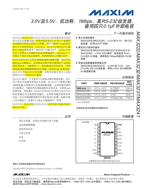
MAX3222/MAX3232/MAX3237/MAX32413.0V至5.5V、低功耗、1Mbps、真RS-232收发器,使用四只0.1µF外部电容________________________________________________________________Maxim Integrated Products119-0273; Rev 7; 1/07MegaBaud和UCSP是Maxim Integrated Products, Inc.的商标。
本文是英文数据资料的译文,文中可能存在翻译上的不准确或错误。
如需进一步确认,请在您的设计中参考英文资料。
有关价格、供货及订购信息,请联络Maxim亚洲销售中心:10800 852 1249 (北中国区),10800 152 1249 (南中国区),或访问Maxim的中文网站:。
M A X 3222/M A X 3232/M A X 3237/M A X 32413.0V至5.5V、低功耗、1Mbps、真RS-232收发器,使用四只0.1µF外部电容2_______________________________________________________________________________________ABSOLUTE MAXIMUM RATINGSELECTRICAL CHARACTERISTICS(V CC = +3.0V to +5.5V, C1–C4 = 0.1µF (Note 2), T A = T MIN to T MAX , unless otherwise noted. Typical values are at T A = +25°C.)Stresses beyond those listed under “Absolute Maximum Ratings” may cause permanent damage to the device. These are stress ratings only, and functional operation of the device at these or any other conditions beyond those indicated in the operational sections of the specifications is not implied. Exposure to absolute maximum rating conditions for extended periods may affect device reliability.Note 1:V+ and V- can have a maximum magnitude of 7V, but their absolute difference cannot exceed 13V.V CC ...........................................................................-0.3V to +6V V+ (Note 1)...............................................................-0.3V to +7V V- (Note 1)................................................................+0.3V to -7V V+ + V- (Note 1)...................................................................+13V Input VoltagesT_IN, SHDN , EN ...................................................-0.3V to +6V MBAUD...................................................-0.3V to (V CC + 0.3V)R_IN.................................................................................±25V Output VoltagesT_OUT...........................................................................±13.2V R_OUT....................................................-0.3V to (V CC + 0.3V)Short-Circuit DurationT_OUT....................................................................ContinuousContinuous Power Dissipation (T A = +70°C)16-Pin TSSOP (derate 6.7mW/°C above +70°C).............533mW 16-Pin Narrow SO (derate 8.70mW/°C above +70°C)....696mW 16-Pin Wide SO (derate 9.52mW/°C above +70°C)........762mW 16-Pin Plastic DIP (derate 10.53mW/°C above +70°C)...842mW 18-Pin SO (derate 9.52mW/°C above +70°C)..............762mW 18-Pin Plastic DIP (derate 11.11mW/°C above +70°C)..889mW 20-Pin SSOP (derate 7.00mW/°C above +70°C).........559mW 20-Pin TSSOP (derate 8.0mW/°C above +70°C).............640mW 28-Pin TSSOP (derate 8.7mW/°C above +70°C).............696mW 28-Pin SSOP (derate 9.52mW/°C above +70°C).........762mW 28-Pin SO (derate 12.50mW/°C above +70°C).....................1W Operating Temperature RangesMAX32_ _C_ _.....................................................0°C to +70°C MAX32_ _E_ _ .................................................-40°C to +85°C Storage Temperature Range.............................-65°C to +150°C Lead Temperature (soldering, 10s).................................+300°CMAX3222/MAX3232/MAX3237/MAX32413.0V至5.5V、低功耗、1Mbps、真RS-232收发器,使用四只0.1µF外部电容_______________________________________________________________________________________3TIMING CHARACTERISTICS—MAX3222/MAX3232/MAX3241(V CC = +3.0V to +5.5V, C1–C4 = 0.1µF (Note 2), T A = T MIN to T MAX , unless otherwise noted. Typical values are at T A = +25°C.)ELECTRICAL CHARACTERISTICS (continued)(V CC = +3.0V to +5.5V, C1–C4 = 0.1µF (Note 2), T A = T MIN to T MAX , unless otherwise noted. Typical values are at T A = +25°C.)A X 3222/M A X 3232/M A X 3237/M A X 32413.0V至5.5V、低功耗、1Mbps、真RS-232收发器,使用四只0.1µF外部电容4_______________________________________________________________________________________典型工作特性Ω, T A = +25°C, unless otherwise noted.)LOAD CAPACITANCE (pF)0246810121416182022150MAX3222/MAX3232SLEW RATEvs. LOAD CAPACITANCELOAD CAPACITANCE (pF)S L E W R A T E (V /µs )20003000100040005000510152025303540MAX3222/MAX3232SUPPLY CURRENT vs. LOAD CAPACITANCEWHEN TRANSMITTING DATALOAD CAPACITANCE (pF)S U P P L Y C U R R E N T (m A )20003000100040005000TIMING CHARACTERISTICS—MAX3237(V CC = +3.0V to +5.5V, C1–C4 = 0.1µF (Note 2), T A = T MIN to T MAX , unless otherwise noted. Typical values are at T A = +25°C.)Note 2:MAX3222/MAX3232/MAX3241: C1–C4 = 0.1µF tested at 3.3V ±10%; C1 = 0.047µF, C2–C4 = 0.33µF tested at 5.0V ±10%.MAX3237: C1–C4 = 0.1µF tested at 3.3V ±5%; C1–C4 = 0.22µF tested at 3.3V ±10%; C1 = 0.047µF, C2–C4 = 0.33µF tested at 5.0V ±10%.Note 3:Transmitter input hysteresis is typically 250mV.MAX3222/MAX3232/MAX3237/MAX32413.0V至5.5V、低功耗、1Mbps、真RS-232收发器,使用四只0.1µF外部电容_______________________________________________________________________________________5-7.5-5.0-2.502.55.07.50MAX3241TRANSMITTER OUTPUT VOLTAGEvs. LOAD CAPACITANCELOAD CAPACITANCE (pF)T R A N S M I T T E R O U T P U T V O L T A G E (V )2000300010004000500046810121416182022240MAX3241SLEW RATEvs. LOAD CAPACITANCELOAD CAPACITANCE (pF)S L E W R A T E (V /µs )20003000100040005000510152025303545400MAX3241SUPPLY CURRENT vs. LOADCAPACITANCE WHEN TRANSMITTING DATALOAD CAPACITANCE (pF)S U P P L Y C U R R E N T (m A )20003000100040005000-7.5-5.0-2.502.55.07.50MAX3237TRANSMITTER OUTPUT VOLTAGE vs. LOAD CAPACITANCE (MBAUD = GND)LOAD CAPACITANCE (pF)T R A N S M I T T E R O U T P U T V O L T A G E (V )200030001000400050000102030504060700MAX3237SLEW RATE vs. LOAD CAPACITANCE(MBAUD = V CC )LOAD CAPACITANCE (pF)S L E W R A T E (V /µs )500100015002000-7.5-5.0-2.502.55.07.50MAX3237TRANSMITTER OUTPUT VOLTAGE vs. LOAD CAPACITANCE (MBAUD = V CC )LOAD CAPACITANCE (pF)T R A N S M I T T E R O U T P U T V O L T A G E (V )5001000150020001020304050600MAX3237SUPPLY CURRENT vs.LOAD CAPACITANCE (MBAUD = GND)LOAD CAPACITANCE (pF)S U P P L Y C U R R E N T (m A )200030001000400050000246810120MAX3237SLEW RATE vs. LOAD CAPACITANCE(MBAUD = GND)LOAD CAPACITANCE (pF)S L E W R A T E (V /µs )2000300010004000500010302040506070MAX3237SKEW vs. LOAD CAPACITANCE(t PLH - t PHL )LOAD CAPACITANCE (pF)1000150050020002500____________________________________________________________________典型工作特性(续)(V CC = +3.3V, 235kbps data rate, 0.1µF capacitors, all transmitters loaded with 3k Ω, T A = +25°C, unless otherwise noted.)M A X 3222/M A X 3232/M A X 3237/M A X 32413.0V至5.5V、低功耗、1Mbps、真RS-232收发器,使用四只0.1µF外部电容6_________________________________________________________________________________________________________________________________________________________________引脚说明MAX3222/MAX3232/MAX3237/MAX32413.0V至5.5V、低功耗、1Mbps、真RS-232收发器,使用四只0.1µF外部电容_______________________________________________________________________________________7_______________________________详细说明双电荷泵电压转换器MAX3222/MAX3232/MAX3237/MAX3241的内部电源由两路稳压型电荷泵组成,只要输入电压(V CC )在3.0V至5.5V范围以内,即可提供+5.5V (倍压电荷泵)和-5.5V (反相电荷泵)输出电压。
国内外压敏电阻型号及参数
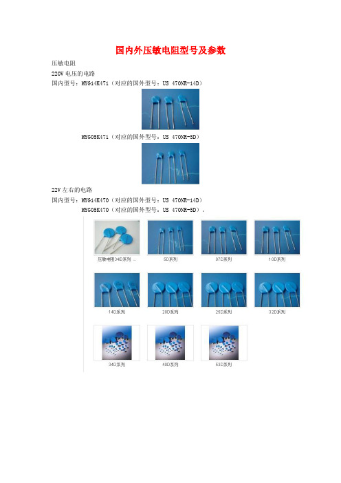
国内外压敏电阻型号及参数压敏电阻220V电压的电路国内型号:MYG14K471(对应的国外型号:US 470NR-14D)MYG05K471(对应的国外型号:US 470NR-5D)22V左右的电路国内型号:MYG14K470(对应的国外型号:US 470NR-14D)MYG05K470(对应的国外型号:US 470NR-5D)。
压敏电阻型号及参数压敏电阻百科名片压敏电阻“压敏电阻"是中国大陆的名词,意思是在一定电流电压范围内电阻值随电压而变,或者是说"电阻值对电压敏感"的阻器。
英文名称叫“Voltage Dependent Resistor”简写为“VDR”,或者叫做“Varistor"。
压敏电阻器的电阻体材料是半导体,所以它是半导体电阻器的一个品种。
现在大量使用的"氧化锌"(ZnO)压敏电阻器,它的主体材料有二价元素(Zn)和六价元素氧(O)所构成。
所以从材料的角度来看,氧化锌压敏电阻器是一种“Ⅱ-Ⅵ族氧化物半导体”。
在中国台湾,压敏电阻器称为"突波吸收器",有时也称为“电冲击(浪涌)抑制器(吸收器)”。
目录[隐藏]1、压敏电阻电路的“安全阀”作用2、压敏电阻的应用类型3、保护用压敏电阻的基本性能4. 压敏电阻的基本参数1、压敏电阻电路的“安全阀”作用2、压敏电阻的应用类型3、保护用压敏电阻的基本性能4. 压敏电阻的基本参数[编辑本段]1、压敏电阻电路的“安全阀”作用压敏电阻有什么用?压敏电阻的最大特点是当加在它上面的电压低于它的阀值" UN"时,流过它的电流极小,相当于一只关死的阀门,当电压超过UN时,流过它的电流激增,相当于阀门打开。
利用这一功能,可以抑制电路中经常出现的异常过电压,保护电路免受过电压的损害。
[编辑本段]2、压敏电阻的应用类型不同的使用场合,应用压敏电阻的目的,作用在压敏电阻上的电压/电流应力并不相同,因而对压敏电阻的要求也不相同,注意区分这种差异,对于正确使用是十分重要的。
22 G3VM-351A D MOS FET 电容式开关新标准系列说明书

G3VM-351A/D MOS FET RelaysNew Standard Series with 350-V LoadVoltage.•Upgraded G3VM-2 Series.•Continuous load current of 120 mA.•Dielectric strength of 2,500 Vrms between I/O.•Operating time of 0.3 ms (typical)RoHS compliant!■Application Examples•Measurement devices•Security systems•Amusement machinesNote:The actual product is marked differently from the imageshown here.■List of Models■DimensionsNote:All units are in millimeters unless otherwise indicated.■Terminal Arrangement/Internal Connections (Top View)■PCB Dimensions (Bottom View)Contact form Terminals Load voltage (peak value)Model Number per stick Number per tape SPST-NO PCB terminals350 VAC G3VM-351A100---Surface-mountingterminalsG3VM-351DG3VM-351D(TR)---1,500G3VM-351A G3VM-351DNote:The actual productis marked different-ly from the imageshown here.Note:The actual productis marked different-ly from the imageshown here.G3VM-351AG3VM-351AG3VM-351A/DG3VM-351A/D■Absolute Maximum Ratings (Ta = 25°C)■Electrical Characteristics (Ta = 25°C)■Recommended Operating ConditionsUse the G3VM under the following conditions so that the Relay will operate properly.■Engineering DataLoad Current vs. Ambient TemperatureG3VM-351A(D)■Safety PrecautionsRefer to “Common Precautions” for all G3VM models.ItemSymbol Rating Unit Measurement ConditionsInputLED forward currentI F 50mARepetitive peak LED forward currentI FP1A 100 µs pulses, 100 pps LED forward current reduction rate∆ I F /°C −0.5mA/°C Ta ≥ 25°CLED reverse voltageV R 5V Connection temperatureT j 125°C OutputOutput dielectric strength V OFF 350V Continuous load current I O 120mA ON current reduction rate ∆ I ON /°C −1.2mA/°C Ta ≥ 25°CConnection temperatureT j 125°C Dielectric strength between input and output (See note 1.)V I-O 2,500Vrms AC for 1 minOperating temperature T a −40 to +85°C With no icing or condensation Storage temperature T stg −55 to +125°C With no icing or condensation Soldering temperature (10 s)---260°C10 s Note:1.The dielectric strength between the input andoutput was checked by applying voltage be-tween all pins as a group on the LED side and all pins as a group on the light-receiving side.Item Symbol Mini-mum Typical Maxi-mum UnitMeasurement conditions InputLED forward voltage V F 1.0 1.15 1.3V I F = 10 mA Reverse currentI R ------10µA V R = 5 V Capacity between terminals C T ---30---pF V = 0, f = 1 MHz Trigger LED forward currentI FT ---13mA I O = 120 mA OutputMaximum resistance with output ONR ON---2535ΩI F = 5 mA,I O = 120 mA, t < 1 s ---3550ΩI F = 5 mA, I O = 120 mA Current leakage when the relay is openI LEAK ------ 1.0µA V OFF = 350 V Capacity between I/O terminals C I-O ---0.8---pF f = 1 MHz, Vs = 0 V Insulation resistance R I-O 1,000------M ΩV I-O = 500 VDC, RoH ≤ 60%Turn-ON time tON ---0.3 1.0ms I F = 5 mA, R L = 200 Ω, V DD = 20 V (See note 2.)Turn-OFF timetOFF---0.11.0ms Note:2.Turn-ON and Turn-OFFTimesItemSymbol MinimumTypicalMaximum UnitOutput dielectric strength V DD------280V Operating LED forward current I F 57.525mA Continuous load current I O ------100mA Operating temperatureT a− 20 ---65°CCommon Precautions!WARNINGBe sure to turn OFF the power when wiring the Relay, other-wise an electric shock may be received.!WARNINGDo not touch the charged terminals of the SSR, otherwise an electric shock may be received.!CautionDo not apply overvoltage or overcurrent to the I/O circuits of the SSR, otherwise the SSR may malfunction or burn.!CautionBe sure to wire and solder the Relay under the proper soldering conditions, otherwise the Relay in operation may generate ex-cessive heat and the Relay may burn.Typical Relay Driving Circuit ExamplesUse the following formula to obtain the LED current limiting resis-tance value to assure that the relay operates accurately.Use the following formula to obtain the LED forward voltage value to assure that the relay releases accurately.Protection from Surge Voltage on the Input TerminalsIf any reversed surge voltage is imposed on the input terminals, insert a diode in parallel to the input terminals as shown in the fol-lowing circuit diagram and do not impose a reversed voltage value of 3V or more.Surge Voltage Protection Circuit ExampleProtection from Spike Voltage on the Output TerminalsIf a spike voltage exceeding the absolute maximum rated value isgenerated between the output terminals, insert a C-R snubber or clamping diode in parallel to the load as shown in the following circuit diagram to limit the spike voltage.Spike Voltage Protection Circuit ExampleUnused Terminals (6-pin models only)Terminal 3 is connected to the internal circuit. Do not connect anything to terminal 3 externally.Pin Strength for Automatic Mountingn order to maintain the characteristics of the relay, the force imposed on any pin of the relay for automatic mounting must not exceed the following.In direction A: 1.96 NIn direction B: 1.96 NLoadTransistor10 to 100 kΩLoadR1 =V CC− V OL− V F (ON) 5 to 20 mAV F (OFF) = V CC− V OH < 0.8 VLoad ConnectionDo not short-circuit the input and output terminals while the relay is operating or the relay may malfunction.Solder MountingPerform solder mounting under the following recommended con-ditions to prevent the temperature of the Relays from rising.<Flow Soldering>Through-hole Mounting (Once Only)Note:We recommend that the suitability of solder mounting be verified under actual conditions.<Reflow Soldering>Surface Mounting DIP or SOP Packages (Twice Max.) Surface Mounting SSOP Packages (Twice Max.)Note: 1.We recommend that the suitability of solder mounting be verified under actual conditions.2.Tape cut SSOPs are packaged without humidity resis-tance. Use manual soldering to mount them.Manual Soldering (Once Only)Manually solder at 350°C for 3 s or less or at 260°C for 10 s or less.SSOP Handling Precautions<Humidity-resistant Packaging>Component packages can crack if surface-mounted components that have absorbed moisture are subjected to thermal stress when mounting. To prevent this, observe the following precau-tions.1.Unopened components can be stored in the packaging at 5to 30°C and a humidity of 90% max., but they should be used within 12 months.2.After the packaging has been opened, components can bestored at 5 to 30°C and a humidity of 60% max., but they should be mounted within 168 hours.3.If, after opening the packaging, the humidity indicator turnspink to the 30% mark or the expiration data is exceeded, bake the components while they are still on the taping reel, and use them within 72 hours. Do not bake the same com-ponents more than once.Baking conditions: 60±5°C, 64 to 72 hExpiration date: 12 months from the seal date(given on the label)4. f the same components are baked repeatedly, the tapedetachment strength will change, causing problems when mounting. When mounting using dehumidifying measures, always take countermeasures against component damage from static electricity.5.Do not throw or drop components. If the laminated packag-ing material is damaged, airtightness will be lost.6.Tape cut SSOPs are packaged without humidity resistance.Use manual soldering to mount them.AC ConnectionDC Single Connection DC Parallel Connection LoadLoadLoadLoadSolder type Preheating SolderingLead solderSnPb150°C60 to 120 s230 to 260°C10 s max.Lead-free solderSnAgCu150°C60 to 120 s245 to 260°C10 s max.Solder type Preheating SolderingLead solderSnPb140→160°C60 to 120 s210°C30 s max.Peak240°C max.Lead-free solderSnAgCu180→190°C60 to 120 s230°C30 to 50 sPeak260°C max.Solder type Preheating SolderingLead solderSnPb140→160°C60 to 120 s210°C30 s max.Peak240°C max.Lead-free solderSnAgCu150→180°C120 s max.230°C30 s max.Peak250°C max.。
FR22中文资料
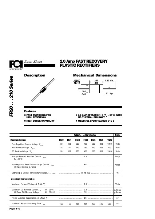
NOTES: 1. Measured @ 1 MHz and applied reverse voltage of 4.0V. 2. Thermal Resistance Junction to Ambient, Jedec Method.
Page 4-11
FR20 . . . 210 Series
Pulse Generator Note 2
+.5A
Reverse Recovery Characteristics tRR
Ratings at 25 Deg. C ambient temperature unless otherwise specified. Single Phase Half Wave, 60 Hz Resistive or Inductive Load. For Capacitive Load, Derate Current by 20%.
FR20 . . . 210 Series Maximum Ratings Peak Repetitive Reverse Voltage...VRRM RMS Reverse Voltage...VR(rms) DC Blocking Voltage...VDC Average Forward Rectified Current...IF(av) TA = 55°C Non-Repetitive Peak Forward Surge Current...IFSM @ Rated Current & Temp Operating & Storage Temperature Range...TJ, TSTRG Electrical Characteristics Maximum Forward Voltage @ 2.0A...VF Maximum DC Reverse Current...IR @ Rated DC Blocking Voltage @ @ 25°C 100°C ............................................. 1.3 ............................................... FR20 50 35 50 FR21 100 70 100 FR22 200 140 200 FR24 400 280 400 FR26 600 420 600 FR28 800 560 800 FR210 1000 700 1000
LM350中文文档
LM3503端3A正电压可调电压调节器钟原2012‐4‐4摘自数据手册LM3503端3A正电压可调电压调节器特性●输出一个1.3V到33V之间的可调的电压●有效3A输出电流●内部温度过载保护●负载规则 (典型: 0.1%)●线性规则 (典型: 0.015%/V)●内部短路电流限制●输出晶体管安全区域补偿描述LM350是一个可调的3端正电压调节器能够提供一个超过3A的电流,输出电压范围1.2V到33V。
内部框图绝对极限等级参数 符号 值 单位输入输出电压差别 VI-VO 35 VDC导热(焊接,10秒) TLEAD 300 ℃ 电压消耗 PD 内部限制 - 工作温度范围 TORR 0~+125 ℃存放温度范围 TSTG -65~+150 ℃典型运用CI:如果调节器处于一个来自电源滤波器可预知的范围则CI是必须的。
CO:输出电容是范围在1uF到100uF之间的铝或陶瓷电容,一般被用于提供改善输出阻抗和消除抖动。
在运用中,LM35O使用了一个名义上的1.25V参考电压,VREF,在输出和调节端之间。
这个参考电压通过R1被传送。
自从电压稳定后,一个稳定的电流I1通过输出偏置电阻R2,产生一个输出电压VO=1.25V(1+R2/R1)+IADJR2;自从来自调节端的IADJ电流(远少于100UF)代表一个错误的术语,LM250被设计成最小的IADJ 和使它非常稳定成线性变化。
这样做,所有静止工作的电流被返回到输出一个最小的负载电流需求。
如果这儿是不合适的负载在输出端,这个输出端电压将上升。
自从LM350是一个浮点型调节器,它只有电压差是电路的重要的性能,工作在高电压时使用涉及到地是可能的。
当IADJ被控制到远少于100uA时,在大多数运用中使用这种术语的错误关系是微不足道的。
LM350AT中文资料

LM150/LM350A/LM3503-Amp Adjustable RegulatorsGeneral DescriptionThe LM150series of adjustable 3-terminal positive voltage regulators is capable of supplying in excess of 3A over a 1.2V to 33V output range.They are exceptionally easy to use and require only 2external resistors to set the output voltage.Further,both line and load regulation are compa-rable to discrete designs.Also,the LM150is packaged in standard transistor packages which are easily mounted and handled.In addition to higher performance than fixed regulators,the LM150series offers full overload protection available only in IC’s.Included on the chip are current limit,thermal overload protection and safe area protection.All overload protection circuitry remains fully functional even if the adjustment termi-nal is accidentally disconnected.Normally,no capacitors are needed unless the device is situ-ated more than 6inches from the input filter capacitors in which case an input bypass is needed.An output capacitor can be added to improve transient response,while bypass-ing the adjustment pin will increase the regulator’s ripple re-jection.Besides replacing fixed regulators or discrete designs,the LM150is useful in a wide variety of other applications.Since the regulator is “floating”and sees only the input-to-output differential voltage,supplies of several hundred volts can be regulated as long as the maximum input to output differential is not exceeded,i.e.,avoid short-circuiting the output.By connecting a fixed resistor between the adjustment pin and output,the LM150can be used as a precision currentregulator.Supplies with electronic shutdown can be achieved by clamping the adjustment terminal to ground which programs the output to 1.2V where most loads draw little current.The part numbers in the LM150series which have a K suffix are packaged in a standard Steel TO-3package,while those with a T suffix are packaged in a TO-220plastic package.The LM150is rated for −55˚C ≤T J ≤+150˚C,while the LM350A is rated for −40˚C ≤T J ≤+125˚C,and the LM350is rated for 0˚C ≤T J ≤+125˚C.Featuresn Adjustable output down to 1.2V n Guaranteed 3A output current n Guaranteed thermal regulation n Output is short circuit protectedn Current limit constant with temperature n P +Product Enhancement tested n 86dB ripple rejectionn Guaranteed 1%output voltage tolerance (LM350A)n Guaranteed max.0.01%/V line regulation (LM350A)nGuaranteed max.0.3%load regulation (LM350A)Applicationsn Adjustable power supplies n Constant current regulators n Battery chargersConnection Diagrams(TO-3STEEL)Metal Can PackageDS009061-4Case is OutputBottom ViewOrder Number LM150K STEELor LM350K STEELSee NS Package Number K02A Order Number LM150K/883See NS Package Number K02C(TO-220)Plastic PackageDS009061-5Front ViewOrder Number LM350AT or LM350T See NS Package Number T03BMay 1998LM150/LM350A/LM3503-Amp Adjustable Regulators©1999National Semiconductor Corporation Absolute Maximum Ratings(Note1)If Military/Aerospace specified devices are required, please contact the National Semiconductor Sales Office/ Distributors for availability and specifications.(Note4)Power Dissipation Internally Limited Input-Output Voltage Differential+35V Storage Temperature−65˚C to+150˚C Lead TemperatureMetal Package(Soldering,10sec.)Plastic Package(Soldering,4sec.)300˚C260˚C ESD Tolerance TBD Operating Temperature RangeLM150−55˚C≤T J≤+150˚C LM350A−40˚C≤T J≤+125˚C LM3500˚C≤T J≤+125˚CElectrical CharacteristicsSpecifications with standard type face are for T J=25˚C,and those with boldface type apply over full Operating Tempera-ture Range.Unless otherwise specified,V IN−V OUT=5V,and I OUT=10mA.(Note2)Parameter Conditions LM150UnitsMin Typ MaxReference Voltage3V≤(V IN−V OUT)≤35V, 1.20 1.25 1.30V10mA≤I OUT≤3A,P≤30WLine Regulation3V≤(V IN−V OUT)≤35V(Note3)0.0050.01%/V0.020.05%/V Load Regulation10mA≤I OUT≤3A(Note3)0.10.3%0.31% Thermal Regulation20ms Pulse0.0020.01%/W Adjustment Pin Current50100µA Adjustment Pin Current Change10mA≤I OUT≤3A,3V≤(V IN−V OUT)≤35V0.25µA Temperature Stability T MIN≤T J≤T MAX1% Minimum Load Current V IN−V OUT=35V 3.55mA Current Limit V IN−V OUT≤10V 3.0 4.5AV IN−V OUT=30V0.31A RMS Output Noise,%of V OUT10Hz≤f≤10kHz0.001% Ripple Rejection Ratio V OUT=10V,f=120Hz,C ADJ=0µF65dBV OUT=10V,f=120Hz,C ADJ=10µF6686dB Long-Term Stability T J=125˚C,1000hrs0.31% Thermal Resistance,Junction K Package 1.2 1.5˚C/W to CaseThermal Resistance,Junction K Package35˚C/W to Ambient(No Heat Sink)Electrical CharacteristicsSpecifications with standard type face are for T J=25˚C,and those with boldface type apply over full Operating Tempera-ture Range.Unless otherwise specified,V IN−V OUT=5V,and I OUT=10mA.(Note2)Parameter Conditions LM350A LM350UnitsMin Typ Max Min Typ Max Reference Voltage I OUT=10mA,T J=25˚C 1.238 1.250 1.262V3V≤(V IN−V OUT)≤35V, 1.225 1.250 1.270 1.20 1.25 1.30V10mA≤I OUT≤3A,P≤30WLine Regulation3V≤(V IN−V OUT)≤35V(Note3)0.0050.010.0050.03%/V0.020.050.020.07%/V Load Regulation10mA≤I OUT≤3A(Note3)0.10.30.10.5%0.310.3 1.5% Thermal Regulation20ms Pulse0.0020.010.0020.03%/W Adjustment Pin Current5010050100µAAdjustment Pin Current Change 10mA≤I OUT≤3A,3V≤(V IN−V OUT)≤35V0.250.25µA2Electrical Characteristics(Continued)Specifications with standard type face are for T J=25˚C,and those with boldface type apply over full Operating Tempera-ture Range.Unless otherwise specified,V IN−V OUT=5V,and I OUT=10mA.(Note2)Parameter Conditions LM350A LM350UnitsMin Typ Max Min Typ Max Temperature Stability T MIN≤T J≤T MAX11% Minimum Load Current V IN−V OUT=35V 3.510 3.510mA Current Limit V IN−V OUT≤10V 3.0 4.5 3.0 4.5AV IN−V OUT=30V0.310.251A RMS Output Noise,%ofV OUT10Hz≤f≤10kHz0.0010.001% Ripple Rejection Ratio V OUT=10V,f=120Hz,C ADJ=0µF6565dBV OUT=10V,f=120Hz,C ADJ=10µF66866686dB Long-Term Stability T J=125˚C,1000hrs0.2510.251% Thermal Resistance,Junction K Package 1.2 1.5˚C/W to Case T Package3434˚C/W Thermal Resistance,Junction K Package35˚C/W to Ambient(No Heat Sink)T Package5050˚C/WNote1:Absolute Maximum Ratings indicate limits beyond which damage to the device may occur.Operating Ratings indicate conditions for which the device is in-tended to be functional,but do not guarantee specific performance limits.For guaranteed specifications and test conditions,see the Electrical Characteristics. Note2:These specifications are applicable for power dissipations up to30W for the TO-3(K)package and25W for the TO-220(T)package.Power dissipation is guaranteed at these values up to15V input-output differential.Above15V differential,power dissipation will be limited by internal protection circuitry.All limits(i.e., the numbers in the Min.and Max.columns)are guaranteed to National’s AOQL(Average Outgoing Quality Level).Note3:Regulation is measured at a constant junction temperature,using pulse testing with a low duty cycle.Changes in output voltage due to heating effects are covered under the specifications for thermal regulation.Note4:Refer to RETS150K drawing for military specifications of the LM150K.Typical Performance CharacteristicsLoad RegulationDS009061-33Current LimitDS009061-34Adjustment CurrentDS009061-35Dropout VoltageDS009061-36Temperature StabilityDS009061-37Minimum Operating CurrentDS009061-38 3Typical Performance Characteristics(Continued)Ripple RejectionDS009061-39Ripple RejectionDS009061-40Ripple RejectionDS009061-41Output Impedance DS009061-42Line Transient Response DS009061-43Load Transient ResponseDS009061-44 4Application HintsIn operation,the LM150develops a nominal 1.25V reference voltage,V REF ,between the output and adjustment terminal.The reference voltage is impressed across program resistor R1and,since the voltage is constant,a constant current I 1then flows through the output set resistor R2,giving an out-put voltage ofSince the 50µA current from the adjustment terminal repre-sents an error term,the LM150was designed to minimize I ADJ and make it very constant with line and load changes.To do this,all quiescent operating current is returned to the output establishing a minimum load current requirement.If there is insufficient load on the output,the output will rise.EXTERNAL CAPACITORSAn input bypass capacitor is recommended.A 0.1µF disc or 1µF solid tantalum on the input is suitable input bypassing for almost all applications.The device is more sensitive to the absence of input bypassing when adjustment or output capacitors are used but the above values will eliminate the possibility of problems.The adjustment terminal can be bypassed to ground on the LM150to improve ripple rejection.This bypass capacitor prevents ripple from being amplified as the output voltage is increased.With a 10µF bypass capacitor 86dB ripple rejec-tion is obtainable at any output level.Increases over 10µF do not appreciably improve the ripple rejection at frequen-cies above 120Hz.If the bypass capacitor is used,it is sometimes necessary to include protection diodes to prevent the capacitor from discharging through internal low current paths and damaging the device.In general,the best type of capacitors to use is solid tanta-lum.Solid tantalum capacitors have low impedance even at high frequencies.Depending upon capacitor construction,it takes about 25µF in aluminum electrolytic to equal 1µF solid tantalum at high frequencies.Ceramic capacitors are also good at high frequencies,but some types have a large decrease in capacitance at frequencies around 0.5MHz.For this reason,0.01µF disc may seem to work better than a 0.1µF disc as a bypass.Although the LM150is stable with no output capacitors,like any feedback circuit,certain values of external capacitance can cause excessive ringing.This occurs with values be-tween 500pF and 5000pF.A 1µF solid tantalum (or 25µF aluminum electrolytic)on the output swamps this effect and insures stability.LOAD REGULATIONThe LM150is capable of providing extremely good load regulation but a few precautions are needed to obtain maxi-mum performance.The current set resistor connected be-tween the adjustment terminal and the output terminal (usu-ally 240Ω)should be tied directly to the output (case)of the regulator rather than near the load.This eliminates line drops from appearing effectively in series with the reference and degrading regulation.For example,a 15V regulator with 0.05Ωresistance between the regulator and load will have a load regulation due to line resistance of 0.05Ωx I OUT .If the set resistor is connected near the load the effective line re-sistance will be 0.05Ω(1+R2/R1)or in this case,11.5times worse.Figure 2shows the effect of resistance between the regula-tor and 240Ωset resistor.With the TO-3package,it is easy to minimize the resistance from the case to the set resistor,by using two separate leads to the case.The ground of R2can be returned near the ground of the load to provide remote ground sensing and im-prove load regulation.PROTECTION DIODESWhen external capacitors are used with any IC regulator it is sometimes necessary to add protection diodes to prevent the capacitors from discharging through low current points into the regulator.Most 10µF capacitors have low enough internal series resistance to deliver 20A spikes when shorted.Although the surge is short,there is enough energy to damage parts of the IC.When an output capacitor is connected to a regulator and the input is shorted,the output capacitor will discharge into the output of the regulator.The discharge current depends on the value of the capacitor,the output voltage of the regu-lator,and the rate of decrease of V IN .In the LM150,this dis-charge path is through a large junction that is able to sustain 25A surge with no problem.This is not true of other types of positive regulators.For output capacitors of 25µF or less,there is no need to use diodes.The bypass capacitor on the adjustment terminal can dis-charge through a low current junction.Discharge occurs when either the input or output is shorted.Internal to the LM150is a 50Ωresistor which limits the peak discharge cur-rent.No protection is needed for output voltages of 25V orDS009061-7FIGURE 1.DS009061-8FIGURE 2.Regulator with Line Resistancein Output Lead5Application Hints(Continued)less and 10µF capacitance.Figure 3shows an LM150with protection diodes included for use with outputs greater than 25V and high values of output capacitance.Schematic DiagramDS009061-9D1protects against C1D2protects against C2FIGURE 3.Regulator with Protection DiodesDS009061-10 6Typical ApplicationsNote:Usually R1=240Ωfor LM150and R1=120Ωfor LM350.1.2V–25V Adjustable RegulatorDS009061-1Full output current not available at high input-output voltages.†Optional —improves transient response.Output capacitors in the range of 1µF to 1000µF of aluminum or tantalum electrolytic are commonly used to provide improved output impedance and rejection of transients.*Needed if device is more than 6inches from filter capacitors.Precision Power Regulator with Low TemperatureCoefficientDS009061-13*Adjust for 3.75V across R1Slow Turn-ON 15V RegulatorDS009061-14Adjustable Regulator with ImprovedRipple RejectionDS009061-15†Solid tantalum*Discharges C1if output is shorted to groundHigh Stability 10V RegulatorDS009061-167Typical Applications(Continued)Digitally Selected OutputsDS009061-17*Sets maximum V OUTRegulator and Voltage ReferenceDS009061-310A RegulatorDS009061-18*Minimum load current 50mA 8Typical Applications(Continued)5V Logic Regulator with Electronic Shutdown *DS009061-19*Min output ≈1.2V0to 30V RegulatorDS009061-20Full output current not available at high input-output voltages5A Constant Voltage/Constant Current RegulatorDS009061-21†Solid tantalum*Lights in constant current mode9Typical Applications(Continued)12V Battery ChargerDS009061-22 Adjustable Current RegulatorDS009061-23Precision Current LimiterDS009061-24*0.4≤R1≤120Ω1.2V–20V Regulator withMinimum Program CurrentDS009061-25*Minimum output current≈4mA3A Current RegulatorDS009061-26 10Typical Applications(Continued)Tracking PreregulatorDS009061-27Adjusting Multiple On-Card Regulatorswith Single Control *DS009061-28†Minimum load —10mA*All outputs within ±100mVAC Voltage Regulator DS009061-29Simple 12V Battery ChargerDS009061-30DS009061-48Use of R S allows low charging rates with fully charged battery.**1000µF is recommended to filter out any input transients11Typical Applications(Continued)Temperature ControllerDS009061-11Light ControllerDS009061-12Adjustable10A RegulatorDS009061-31Current Limited6V ChargerDS009061-32*Sets peak current(2A for0.3Ω)**1000µF is recommended to filter out any input transients.6A RegulatorDS009061-2 12Physical Dimensions inches(millimeters)unless otherwise noted2Lead TO-3Metal Can Package(K)Order Number LM150K STEEL or LM350K STEELNS Package Number K02A2Lead TO-3Metal Can Package(K)Mil-Aero ProductOrder Number LM150K/883NS Package Number K02C13Physical Dimensions inches(millimeters)unless otherwise noted(Continued)LIFE SUPPORT POLICYNATIONAL’S PRODUCTS ARE NOT AUTHORIZED FOR USE AS CRITICAL COMPONENTS IN LIFE SUPPORT DE-VICES OR SYSTEMS WITHOUT THE EXPRESS WRITTEN APPROVAL OF THE PRESIDENT OF NATIONAL SEMI-CONDUCTOR CORPORATION.As used herein:1.Life support devices or systems are devices or sys-tems which,(a)are intended for surgical implant intothe body,or(b)support or sustain life,and whose fail-ure to perform when properly used in accordancewith instructions for use provided in the labeling,canbe reasonably expected to result in a significant injuryto the user.2.A critical component is any component of a life supportdevice or system whose failure to perform can be rea-sonably expected to cause the failure of the life supportdevice or system,or to affect its safety or effectiveness.National SemiconductorCorporationAmericasTel:1-800-272-9959Fax:1-800-737-7018Email:support@National SemiconductorEuropeFax:+49(0)180-5308586Email:europe.support@Deutsch Tel:+49(0)180-5308585English Tel:+49(0)180-5327832Français Tel:+49(0)180-5329358Italiano Tel:+49(0)180-5341680National SemiconductorAsia Pacific CustomerResponse GroupTel:65-2544466Fax:65-2504466Email:sea.support@National SemiconductorJapan Ltd.Tel:81-3-5639-7560Fax:81-3-5639-75073Lead Molded TO-220(T)Order Number LM350AT or LM350TNS Package Number T03BLM15/LM35A/LM353-AmpAdjustableRegulatorsNational does not assume any responsibility for use of any circuitry described,no circuit patent licenses are implied and National reserves the right at any time without notice to change said circuitry and specifications.。
MEMORY存储芯片MAX3232ESE中文规格书
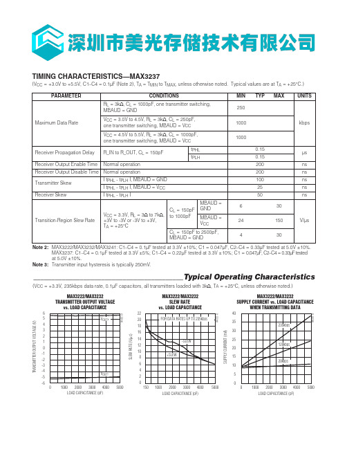
__________________________________________Typical Operating Characteristics(V CC = +3.3V, 235kbps data rate, 0.1µF capacitors, all transmitters loaded with 3k Ω, T A = +25°C, unless otherwise noted.)TIMING CHARACTERISTICS—MAX3237(V CC = +3.0V to +5.5V, C1–C4 = 0.1µF (Note 2), T A = T MIN to T MAX , unless otherwise noted. Typical values are at T A = +25°C.)Note 2:MAX3222/MAX3232/MAX3241: C1–C4 = 0.1µF tested at 3.3V ±10%; C1 = 0.047µF, C2–C4 = 0.33µF tested at 5.0V ±10%.MAX3237: C1–C4 = 0.1µF tested at 3.3V ±5%; C1–C4 = 0.22µF tested at 3.3V ±10%; C1 = 0.047µF, C2–C4 = 0.33µF tested at 5.0V ±10%.Note 3:Transmitter input hysteresis is typically 250mV.-6-5-4-3-2-101234560MAX3222/MAX3232TRANSMITTER OUTPUT VOLTAGEvs. LOAD CAPACITANCELOAD CAPACITANCE (pF)T R A N S M I T T E R O U T P U T V O L T A G E (V )20003000100040005000246810121416182022150MAX3222/MAX3232SLEW RATEvs. LOAD CAPACITANCELOAD CAPACITANCE (pF)S L E W R A T E (V /μs )20003000100040005000510152025303540MAX3222/MAX3232SUPPLY CURRENT vs. LOAD CAPACITANCEWHEN TRANSMITTING DATALOAD CAPACITANCE (pF)S U P P L Y C U R R E N T (m A )20003000100040005000MAX3222/MAX3232/MAX3237/MAX32413.0V to 5.5V, Low-Power, up to 1Mbps, True RS-232 Transceivers Using Four 0.1µF External CapacitorsFigure 4a. MAX3241 Transmitter Output Voltage vs. Load Current per Transmitter3.0V to 5.5V , Low-Power, up to 1Mbps, True RS-232Transceivers Using Four 0.1µF External CapacitorsMAX3222/MAX3232/MAX3237/MAX3241CC = 3.3V5μs/divFigure 5. Loopback Test CircuitHigh Data RatesThe MAX3222/MAX3232/MAX3241 maintain the RS-232±5.0V minimum transmitter output voltage even at high data rates. Figure 5 shows a transmitter loopb ack test circuit. Figure 6 shows a loopb ack test result at 120kbps, and Figure 7 shows the same test at 235kbps. For Figure 6, all transmitters were driven simultaneously at 120kb ps into RS-232 loads in parallel with 1000pF. For Figure 7, a single transmitter was driven at 235kbps, and all transmitters were loaded with an RS-232 receiver in parallel with 1000pF.The MAX3237 maintains the RS-232 ±5.0V minimum transmitter output voltage at data rates up to 1Mb ps. Figure 8 shows a loopb ack test result at 1Mb ps with MBAUD = V CC . For Figure 8, all transmitters were loaded with an RS-232 receiver in parallel with 250pF.fdzfdfbbFigure 6. MAX3241 Loopback Test Result at 120kbpsCC = 3.3V2μs/divFigure 7. MAX3241 Loopback Test Result at 235kbps0V +5V 0V -5V +5V 0VT_INT_OUT = R_IN 5k R_OUT 150pF200ns/divCC = 3.3VFigure 8. MAX3237 Loopback Test Result at 1000kbps (MBAUD = V CC )___________________Chip Topography___________________Chip InformationT1INT2IN 0.087"(2.209mm)R2OUTR2IN T2OUT R1OUTR1INT1OUTV CCV+C1+ENC1-C2+C2-V-GNDTRANSISTOR COUNT: 339SUBSTRATE CONNECTED TO GNDMAX3222/MAX3232/MAX3237/MAX3241 3.0V to 5.5V, Low-Power, up to 1Mbps, True RS-232Transceivers Using Four 0.1µF External Capacitors。
RLN22 NAMUR 隔离信号放大器 24 V DC 产品说明书
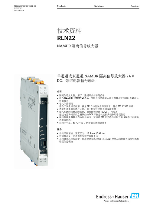
单通道或双通道NAMUR 隔离信号放大器24 V DC,带继电器信号输出应用•隔离信号放大器,用于二进制开关信号的传输•符合NAMUR(EN60947-5-6)的接近传感器输入和开路触点或带电阻性耦合元件的触点•电气3路隔离适合于安全相关应用,满足SIL 2功能安全等级要求,符合IEC 61508标准•选装配备电阻性耦合元件,用于机械开关触点的线路监测•输入回路的线路故障监测,如断路和短路(LFD),可分离通过电源和错误信息模块处的DIN 导轨总线连接头获取组错误信息•输出侧继电器触点作为信号输出,可通过DIP 开关选择动作方向(操作状态或静态电流状态)•应用于–40 … 60 °C (–40 … 140 °F)的环境温度下优势•外壳结构紧凑,宽度仅为:12.5 mm (0.49 in)•有防爆认证,允许选择安装在防爆2区•采用直插式接线端子,快速便捷完成接线;通过DIN 导轨总线连接头选配电源和错误信息模块Products Solutions Services技术资料RLN22NAMUR 隔离信号放大器TI01560K/28/ZH/02.21-00715777272021-10-19RLN222Endress+Hauser目录功能与系统设计 (3)产品描述 ..................................3可靠性....................................3输入 (3)类型......................................3输入数据.. (3)输出.....................................3继电器输出参数..............................3报警信号...................................3防爆连接参数................................4电气隔离...................................4电源.....................................4接线端子分配................................4连接电源...................................4性能参数...................................4接线端子...................................4性能参数 (5)响应时间 (5)安装 (5)安装位置...................................5安装DIN 盘装型设备 (5)环境条件 (5)重要环境条件................................5抗冲击性和抗振性............................5电磁兼容性(EMC) (5)机械结构 (6)设计及外形尺寸..............................6重量......................................6颜色......................................6材质........ (6)显示与操作单元 (7)现场操作...................................7真值表,单通道..............................8真值表,双通道 (8)订购信息..................................8附件.....................................9设备专用附件................................9服务专用附件.. (9)证书和认证 (9)CE 认证....................................9功能安全性.. (10)文档资料 (10)《简明操作指南》(KA)......................10《操作手册》(BA).........................10《安全指南》(XA).........................10补充文档资料...............................10RLN22Endress+Hauser 3功能与系统设计产品描述产品设计NAMUR 隔离放大器,单通道•在订购选项中选择“单通道转换触点”,单通道NAMUR 隔离信号放大器可配备电阻性耦合元件,用于操作接近开关(符合EN 60947-5-6(NAMUR)标准)、断开触点和机械触点。
MAX232中文资料(官方版)
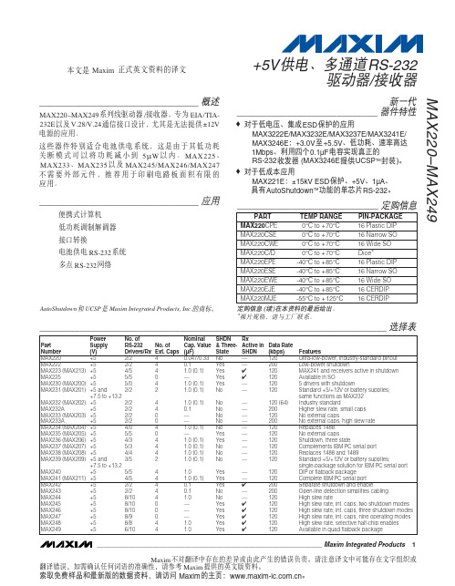
新一代 器件特性 ____________________________
♦ 对于低电压、集成 ESD 保护的应用 MAX3222E/MAX3232E/MAX3237E/MAX3241E/ MAX3246E:+3.0V 至 +5.5V、低功耗、速率高达 1Mbps、利用四个 0.1µF 电容实现真正的 RS-232 收发器 (MAX3246E 提供 UCSPTM 封装 )。 ♦ 对于低成本应用 MAX221E:±15kV ESD 保护、+5V、1µA、 具有 AutoShutdownTM 功能的单芯片 RS-232。
________________________________ 应用
便携式计算机 低功耗调制解调器 接口转换 电池供电 RS-232 系统 多点 RS-232 网络
_____________________________ 定购信息
PART MAX220CPE MAX220CSE MAX220CWE MAX220C/D MAX220EPE MAX220ESE MAX220EWE MAX220EJE MAX220MJE TEMP RANGE 0°C to +70°C 0°C to +70°C 0°C to +70°C 0°C to +70°C -40°C to +85°C -40°C to +85°C -40°C to +85°C -40°C to +85°C -55°C to +125°C PIN-PACKAGE 16 Plastic DIP 16 Narrow SO 16 Wide SO Dice* 16 Plastic DIP 16 Narrow SO 16 Wide SO 16 CERDIP 16 CERDIP
贴片电容电阻参数及详解
公司主营产品相关知识一.贴片电容贴片电容全称:多层(积层,叠层)片式陶瓷电容器,也称为贴片电容,片容。
英文缩写:MLCC。
1.品牌:日系:TDK 、村田(MURATA)、京瓷(Kyocera)、太阳诱电(TAIYO YUDEN)、松下(Panasonic)、罗姆(ROHM)、KOA(KOA SpeerElectronics.Inc)台系:国巨(YAGEO)、华科(WALSIN)韩系:三星(Samsung)国产:风华(FH)、宇阳(E YANG)2.主要参数:容值电压误差材质(精度)尺寸3.各个参数详解:①.容值容值的算法常用容值单位:UF 、 NF 、 PF (微法、纳法、皮法)容值都为千进制(以上前者为后者的1000倍)如:1,000PF =1NF =102 =0.001UF10,000PF =10NF =103 =0.01UF100,000PF =100NF =104 =0.1UF另注:5PF = 509用二位数字表示有效数字,再用一个字母表示数值的量级。
如:1p2表示1.2pF, 220n表示0.22uF,3u3表示3.3uF, 2m2表示2200uF。
另一种表示法,是用三位数字表示电容量,最后用一个字母表示误差。
三位数字中的前两位表示有效值,第三位表示10的n次方,n 一般为1—8。
特殊情况是:当n=9时,不表示10的9次方,而表示为10的 -1次方。
例如:"102"表示10*100=1000pF"223"表示22*1000=22000pF=0.022uF"474"表示47*10000=0.47uF"159"表示15*0.1=1.5pF②.电压各个品牌电容的电压表示方法各不相同。
系列电压有6.3V、10V、16V、25V、50V、100V、200V、500V、1000V、2000V、3000V、 4000V③.误差电容的容值误差通常用字符表示:第一种,绝对误差,通常以电容量的值的绝对误差表示,以PF为单位,即:B代表±0.1PF、C代表±0.25PF、D代表±0.5PF,Y代表±1PF,A代表±1.5PF,V代表±5PF。
施耐德RM22TR33 RM22控制继电器,三相监测 数据表

Product data sheetCharacteristicsRM22TR33RM22控制继电器,三相监测,380…480Vac, 2 C/O主要信息产品系列Harmony Control Relays 继电器类型控制继电器产品类型3-phase control relay 电网相数 3 相继电器名称RM22TR 继电器监测参数过压与欠压监测 相位顺序相位故障监测延时类型可调的 0.1...30 s, +/- 10 % 满量程值 Tt- time delay upon fault 开关能力以 VA 2000 VA测量范围380...480 V 电压 AC 触点类型2 OC补充信息复位时间1500 Ms 在最大电压最大开关电压250 V AC最小开关电流 [Imin]10 MA 在…上 5 V DC 最大开关电流8 A AC 额定电源电压 [Us]交流/直流电源电压范围304…576 V 交流控制电压限额- 20 % + 20 % Un功耗 VA 15 VA 在…上 480 V AC 60 Hz 电压监测阈值< 100 V AC 供电频率50...60 Hz +/- 10 %输出触头 2 C/O 额定输出电流8 A设置精度+/- 10 % 满量程开关阈误差<= 0.05 % 每摄氏度 基于许可的环境空气温度而定 <= 1 % 供电电压范围内延时准确性设置10 P延时误差<= 0.05 % 每摄氏度 基于许可的环境空气温度而定 <= 1 % 供电电压范围内迟滞2 % 固定式 的 可选通电时的上涨延迟650 MsMaximum measuring cycle 150 Ms 以真 rms 值测量周期阈值调节电压2...20 % 选择的 UnT h e i n f o r m a t i o n p r o v i d e d i n t h i s d o c u m e n t a t i o n c o n t a i n s g e n e r a l d e s c r i p t i o n s a n d /o r t e c h n i c a l c h a r a c t e r i s t i c s o f t h e p e r f o r m a n c e o f t h e p r o d u c t s c o n t a i n e d h e r e i n .T h i s d o c u m e n t a t i o n i s n o t i n t e n d e d a s a s u b s t i t u t e f o r a n d i s n o t t o b e u s e d f o r d e t e r m i n i n g s u i t a b i l i t y o r r e l i a b i l i t y o f t h e s e p r o d u c t s f o r s p e c i f i c u s e r a p p l i c a t i o n s .I t i s t h e d u t y o f a n y s u c h u s e r o r i n t e g r a t o r t o p e r f o r m t h e a p p r o p r i a t e a n d c o m p l e t e r i s k a n a l y s i s , e v a l u a t i o n a n d t e s t i n g o f t h e p r o d u c t s w i t h r e s p e c t t o t h e r e l e v a n t s p e c i f i c a p p l i c a t i o n o r u s e t h e r e o f .N e i t h e r S c h n e i d e r E l e c t r i c I n d u s t r i e s S A S n o r a n y o f i t s a f f i l i a t e s o r s u b s i d i a r i e s s h a l l b e r e s p o n s i b l e o r l i a b l e f o r m i s u s e o f t h e i n f o r m a t i o n c o n t a i n e d h e r e i n .电压范围380...480 V P-P重复精度+/- 0.5 % 适用 输入和测量电路+/- 3 % 适用 时间延时测量误差在整个量程上 < 1 % 带有电压变化< 0.05 %/°C 带有温度变化响应时间<= 300 ms过电压种类III 符合 IEC 60664-1III 符合 UL 508绝缘电阻> 100 MΩ 在…上 500 V DC 符合 IEC 60255-27安装位置任意位置接线能力螺钉端子, 2 x 0.5...2 x 2.5 mm² (AWG 20...AWG 14) 硬线 不带接线端子螺钉端子, 2 x 0.2...2 x 1.5 mm² (AWG 24...AWG 16) 软线 带接线端子螺钉端子, 1 x 0.5...1 x 3.3 mm² (AWG 20...AWG 12) 硬线 不带接线端子螺钉端子, 1 x 0.2...1 x 2.5 mm² (AWG 24...AWG 14) 软线 带接线端子紧固扭矩0.6…1 N.M 符合 IEC 60947-1覆盖材料阻燃性塑料LED状态LED (黄色) 继电器ONLED (绿色) 通电安装方式35 mm DIN 轨 符合 IEC 60715电气寿命100000 次机械寿命10000000 次使用类别AC-15 符合 IEC 60947-5-1DC-13 符合 IEC 60947-5-1AC-1 符合 IEC 60947-4-1DC-1 符合 IEC 60947-4-1额定电源电压 [Us], self-powered 电源安全可靠的数据MTTFd = 388.1 yearsB10d = 350000触点材料无镉控制类型With test button宽度22.5 Mm净重0.09 Kg环境抗瞬时断电10 Ms电磁兼容性免用于居住、商业与轻工业环境的传输标准 conforming to IEC 61000-6-1免用于工业环境 conforming to IEC 61000-6-2居住、商业与轻工业环境的传输标准 conforming to IEC 61000-6-3工业环境的传输标准 conforming to IEC 61000-6-4抗静电干扰 - test level: 6 kV 3级 (接触放电) conforming to IEC 61000-4-2抗静电干扰 - test level: 8 kV 3级 (空气放电) conforming to IEC 61000-4-2射频电磁场辐射抗扰度试验 - test level: 10 V/m 3级 conforming to IEC 61000-4-3抗快速瞬变 - test level: 4 kV 4级 (直连) conforming to IEC 61000-4-4抗快速瞬变 - test level: 2 kV 4级 (电容耦合) conforming to IEC 61000-4-4浪涌放电抗干扰 - test level: 4 kV 4级 (共模) conforming to IEC 61000-4-5浪涌放电抗干扰 - test level: 2 kV 4级 (差模) conforming to IEC 61000-4-5传导和辐射干扰 B组1 conforming to CISPR 11传导和辐射干扰 B级 conforming to CISPR 22符合标准IEC 60255-1产品认证GL[RETURN]CSA[RETURN]RCM[RETURN]CE[RETURN]EAC[RETURN]CCC[RETURN]UL 贮存环境温度-40…70 °C环境温度-20…50 °C 在…上 60 Hz-20…60 °C 在…上 50 Hz AC/DC相对湿度93…97 % 在…上 25…55 °C 符合 IEC 60068-2-30抗振动0.075 mm (f= 10…58.1 Hz) 非运行 符合 IEC 60068-2-61 gn (f= 10…58.1 Hz) 非运行 符合 IEC 60068-2-60.035 mm (f= 58.1…150 Hz) 运行期间 符合 IEC 60068-2-60.5 gn (f= 58.1…150 Hz) 运行期间 符合 IEC 60068-2-6抗冲击15 gn (持续时间 = 11 ms) 适用 非运行 符合 IEC 60068-2-275 gn (持续时间 = 11 ms) 适用 运行期间 符合 IEC 60068-2-27IP 保护等级IP20 符合 IEC 60529 (螺钉端子)IP40 符合 IEC 60529 (外壳)IP50 符合 IEC 60529 (前面板)污染等级 3 符合 IEC 60664-13 符合 UL 508介电测试绕组与绕组、绕组对地电压 2.5 KV AC 50 Hz, 1分钟 符合 IEC 60255-27包装单位Unit Type of Package 1PCENumber of Units in Package 11Package 1 Height 2.6 CmPackage 1 Width8.2 CmPackage 1 Length9.5 CmPackage 1 Weight104.0 GUnit Type of Package 2S02Number of Units in Package 240Package 2 Height15.0 CmPackage 2 Width30.0 CmPackage 2 Length40.0 CmPackage 2 Weight 4.535 KgUnit Type of Package 3P06Number of Units in Package 3640Package 3 Height75.0 CmPackage 3 Width60.0 CmPackage 3 Length80.0 CmPackage 3 Weight81.06 Kg可持续性产品类型Green Premium 产品REACh法规REACh 声明欧盟ROHS指令主动合规性(超出欧盟 RoHS 法定范围的产品)Mercury free支持RoHS exemption information支持中国 ROHS 管理办法中国 ROHS 声明环境披露产品环境文件流通资料产品使用寿命终期信息WEEE该产品必须经特定废物回收处理后弃置于欧盟市场,绝不可丢弃于垃圾桶中。
欧姆龙-3G3MX2变频器介绍

电压等级
功率(KW)
0.1 0.2
型号
3G3MX2-AB001 3G3MX2-AB002-Z 3G3MX2-AB004-Z 3G3MX2-AB007-Z
单相200V
0.4 0.75
1.5 2.2
欧姆龙武汉
3G3MX2-AB015-Z 3G3MX2-AB022-Z
电压等级
功率(KW)
0.1 0.2 0.4 0.75
在低频时,由于V较小,定子阻抗压降的分量比较显著,不在能忽略。 当转矩增大到最大值以后,特性就向下弯了。 最大转矩随着f的降低而减少。 尽管可以采取低频补偿措施,但通常认为V/F控制的下限频率应不小于 0.3HZ.
欧姆龙武汉
3.V/f、矢量控制调速原理
• • • 3)矢量控制 由于V/F控制是基于异步电动机的静态数学模型,因此,其 动态指标不高,对于轧钢、造纸等行业,还需要高品质动态 指标的控制方式。 矢量控制是根据交流电动机的动态数字模型,利用坐标变换 手段,将电机的定子电流分解成磁场分量电流和转矩分量电 流,通过对一次定子电流的大小、频率及相位进行适当的控 制,可实现矢量分解及控制。
•MX2 •电机:3.7kW 4P 200V •控制方式:无传感器矢量控制
•转矩[%] • [N・m]
•
•
200[%] •(39.3 [N・m])
100[%] •(19.6 [N・m])
•
•
100[%] •(19.6 [N・m])
•0 •1 •3 •6 •运行频率[Hz]
欧姆龙武汉
•0 •1 •3
•0.5
欧姆龙武汉
• MX2-z 商品产品线
•MX2产品的输入电压有单相200V、三相200V和三相380V三种规格,具体 功率范围如下表。
- 1、下载文档前请自行甄别文档内容的完整性,平台不提供额外的编辑、内容补充、找答案等附加服务。
- 2、"仅部分预览"的文档,不可在线预览部分如存在完整性等问题,可反馈申请退款(可完整预览的文档不适用该条件!)。
- 3、如文档侵犯您的权益,请联系客服反馈,我们会尽快为您处理(人工客服工作时间:9:00-18:30)。
Large Can Aluminum Electrolytic Capacitors
FEATURES
• NEW SIZES FOR LOW PROFILE AND HIGH DENSITY DESIGN OPTIONS • EXPANDED CV VALUE RANGE
• HIGH RIPPLE CURRENT
• LONG LIFE • CAN-TOP SAFETY VENT
• DESIGNED AS INPUT FILTER OF SMPS • STANDARD 10mm (.400") SNAP-IN SPACING NRLM Series
SPECIFICATIONS
(* 47,000µF add 0.14, 68,000µF add 0.35.)Notice for Mounting
The space from the top of the can shall be more than (3mm) from chassis or other construction materials so that safety vent has room to expand in case of emer g en c y.
Sleeve Color: Dark
Blue
Can Top Safety Vent
Insulation Sleeve and Minus Polarity Marking
(4.0mm Leads Available As Option)
D+1Max.
L ± 2
6.3 ± 10.8
10
(-)
(+)
MAXIMUM EX P AN S ION
FOR SAFETY VENT Approx. 3.0mm
Recommended PC Board Mounting Holes:
10 ± .1
∅= 2 ± 0.1
D ∅ ± 0.5
Chassis
PC Board
PRECAUTIONS
Please review the notes on correct use, safety and precautions found on pages T10 & T11
of NIC’s Electrolytic Capacitor catalog . Operating Temperature Range
-40 ~ +85°C
-25 ~ +85°C Rated Voltage Range 16 ~ 250Vdc 350 ~ 450Vdc Rated Capacitance Range 180 ~ 68,000µF
56 ~ 680µF
Capacitance Tolerance ±20% (M)Max. Leakage Current (µA)After 5 minutes (20°C)
3 x C(µF)V
Max. Tan δ
at 120Hz/20°C W.V. (Vdc)162535506380100160~450Tan δ max.
0.50*0.40*0.350.300.250.200.200.15Surge Voltage
W.V. (Vdc)162535506380100160S.V. (Vdc)
2032446379100125200W.V. (Vdc)180200250350400450--S.V. (Vdc)220250300400450500--Ripple Current
Correction Factors Frequency (Hz)50601001205001K 10K ~ 50K -Multiplier at 85°C
0.750.800.95 1.00 1.05 1.08 1.15-Low Temperature
Stability (10 to 250Vdc)
Temperature (°C)
0-25-40-----Capacitance Change
-5%-15%-30%-----Impedance Ratio 1.5
39-----Load Life Test
2,000 hours at +85°C
Capacitance Change
Within ±20% of initial measured value Tan δ
Less than 200% of specifi ed maximum value
Leakage Current Less than specifi ed maximum value Shelf Life Test
1,000 hours at +85°C (no load)Capacitance Change Within ±20% of initial measured value Tan δ
Less than 200% of specifi ed maximum value
Leakage Current Less than specifi ed maximum value Surge Voltage Test Per JIS-C-5141 (table #6, #4)Surge voltage applied: 30 seconds
"On" and 5.5 minutes no voltage "Off"
Capacitance Change Within ±20% of initial measured value Tan δLess than 200% of specifi ed maximum value
Leakage Current Less than specifi ed maximum value Soldering Effect
Refer to MIL-STD-202F Method 210A Capacitance Change Within ±10% of initial measured value
Tan δ
Less than specifi ed maximum value Leakage Current
Less than specifi ed maximum value
RoHS Compliant
includes all homogeneous materials
*See Part Number System for Details
Large Can Aluminum Electrolytic Capacitors
NRLM Series
NRLM 222 M 50V 20X25 F
RoHS compliant Case Size (mm) Voltage Rating Tolerance Code PART NUMBER SYSTEM
Large Can Aluminum Electrolytic Capacitors NRLM Series STANDARD PRODUCT LIST, CASE SIZE AND SPECIFICATIONS。
