原子钟8130 Militarized Rubidium Frequency Standard
有关原子钟的中英文翻译资料
A.2 中文翻译摘自:光学学报原子钟原子钟,它最初本是由物理学家创造出来用于探索宇宙本质的;他们从来没有想过这项技术有朝一日竟能应用于全球的导航系统上。
根据量子物理学的基本原理,原子是按照不同电子排列顺序的能量差,也就是围绕在原子核周围不同电子层的能量差,来吸收或释放电磁能量的。
这里电磁能量是不连续的。
当原子从一个“能量态”跃迁至低的“能量态”时,它便会释放电磁波。
这种电磁波特征频率是不连续的,这也就是人们所说的共振频率。
同一种原子的共振频率是一定的—例如铯133的共振频率为每秒9192631770周。
因此铯原子便用作一种节拍器来保持高度精确的时间。
30年代,拉比和他的学生们在哥伦比亚大学的实验室里研究原子和原子核的基本特性。
也就是在这里,他们在依靠这种原子计时器来制造时钟方面迈出了有价值的第一步。
在其研究过程中,拉比发明了一种被称为磁共振的技术。
依靠这项技术,他便能够测量出原子的自然共振频率。
为此他还获得了1944年诺贝尔奖。
同年,他还首先提出“要讨论讨论这样一个想法”(他的学生这样说道),也就是这些共振频率的准确性如此之高,完全可以用来制作高精度的时钟。
他还特别提出要利用所谓原子的“超精细跃迁”的频率。
这种超精细跃迁指的是随原子核和电子之间不同的磁作用变化而引起的两种具有细微能量差别的状态之间的跃迁。
在这种时钟里,一束处于某一特定“超精细状态”的原子束穿过一个振荡电磁场。
当原子的超精细跃迁频率越接近磁场的振荡频率,原子从磁场中吸收的能量就越多,从而产生从原始超精细状态到令一状态的跃迁。
通过一个反馈回路,人们能够调整振荡场的频率直到所有的原子完成了跃迁。
原子钟就是利用振荡场的频率即保持与原子的共振频率完全相同的频率作为产生时间脉冲的节拍器。
人们日常生活需要知道准确的时间,生产、科研上更是如此。
人们平时所用的钟表,精度高的大约每年会有1分钟的误差,这对日常生活是没有影响的,但在要求很高的生产、科研中就需要更准确的计时工具。
看原子钟的原理
看原子钟的原理140亿年内误差不超过1/10秒!原子钟让计时精度走向极限2021年01月15日新浪科技综合根据原子物理学的基本原理,当原子从一个能量态跃迁至低的能量态时,它便会释放电磁波。
同一种原子的电磁波特征频率是一定的,可用作一种节拍器来保持高度精确的时间。
原子钟就是利用保持与原子的电磁波特征频率同步作为产生时间脉冲的节拍器。
根据原子物理学的基本原理,原子是按照围绕在原子核周围不同电子层的能量差,来吸收或释放电磁能量的。
当原子从一个“能量态”跃迁至更低的“能量态”时,它便会释放电磁波。
这种不连续的电磁波的频率,就是人们所说的共振频率。
同一种原子的共振频率是一定的——例如铯133的共振频率为每秒9192631770周。
原子钟就是使用激光来测量原子的共振频率,从而实现精准计时。
氢原子钟将氢原子保持在四周由特殊材料制成的容器中,从而使氢原子保持所需的能级,而不至于太快失去其较高的能量状态,环境温度变化及微波谐振腔老化会引起其输出频率的变化,从而导致氢原子钟长期性能变差,为了减小这些影响,可借助自动调谐器来确保谐振腔的频率始终工作在所需的频率上,并采用新的温度控制系统来改善氢原子钟的长期性能。
铷原子钟是所有原子钟中最简单也最紧凑的一种,它使用装有铷气的玻璃腔,铷气在周围的微波频率恰到好处时,就会按照铷原子的振荡频率改变其光吸收率。
铷原子钟溯源同步到GPS卫星铯原子钟上,输出频率几乎没有漂移,性能与铯原子钟相近,而且不存在铯原子钟那样铯束管寿命短需要高成本更换的问题。
由于引力会影响时间的流逝,因此距离海平面更近的时钟实际上比珠穆朗玛峰上的时钟慢一点,这意味着物理学家可以使用原子钟来测定地球的形状、大小和地球重力场等,这是一个被称为大地测量学的科学领域。
如果原子钟能够更准确地测量原子振荡,那么它们将足够灵敏以检测诸如暗物质和引力波之类的现象。
看了文章当原子从一个能量态跃迁至低的能量态时,它便会释放电磁波,原子是带电的。
原子钟的精确值

原子钟的精确值原子钟是一种利用精确的原子振荡频率来测量时间的仪器。
它是现代科学和技术领域中最精确的时间标准之一。
原子钟的精确值是以一个实际的原子频率来定义的,通常是通过气体或固体中的原子核或电子的特定能级间的跃迁频率来实现的。
原子钟的精确值通常以秒为单位,定义为国际单位制中的基本单位。
目前,世界上最准确的原子钟是通过测量铯(Cs)原子的振荡频率来实现的,其精确值为每秒9,192,631,770次跃迁。
铯原子钟的工作原理基于铯-133同位素的性质。
在一个典型的铯原子钟中,铯原子会被冷却至接近绝对零度(-273.15摄氏度)并被捕获在一个恒温的腔体中。
然后,通过激光束或微波辐射来激发铯原子内的能级跃迁。
铯原子钟中的精确值通过以下过程实现:首先,激光或微波辐射会激发铯原子从基态跃迁到高能级的超精细能级。
然后,一个周期性的微波信号被施加到铯原子中,使其内部的电子从高能级回退到基态。
当微波信号的频率等于特定跃迁的频率时,原子会吸收这个信号的能量并发生辐射跃迁。
通过测量微波信号的频率,我们可以确定铯原子内特定跃迁的频率。
通过比较这一频率与国际标准定义的秒数,我们可以得到原子钟的精确值。
国际上的原子钟被公认为是最准确的时间标准,它们可以在实验室、天文台和卫星等场所使用。
原子钟的精确值对于现代社会的许多方面至关重要。
它们用于卫星导航系统、电信网络、金融交易和科学研究等领域。
在导航系统中,原子钟通过提供高精度的时间信息,使得卫星能够精确确定地面位置。
在电信网络中,原子钟用于确保精确的数据传输和同步。
在金融交易中,原子钟可以提供精确的时间戳,以确保交易的准确性和安全性。
在科学研究中,原子钟用于测量时间间隔、粒子的速度和天体运动等。
虽然原子钟被认为是最准确的时间测量仪器,但它们也存在一些局限性。
其中一个问题是原子钟的体积和复杂性。
目前的原子钟主要是实验室级别的设备,其尺寸较大且不能轻松移动。
此外,原子钟也需要特殊的环境条件和高度的技术要求,以保持其精确度和稳定性。
原子钟的原理应用有哪些

原子钟的原理应用有哪些原子钟的原理原子钟是利用原子内部的电子转跃来测量时间的高精度时钟。
它基于原子的稳定性和精确的振荡频率来实现时间的准确测量。
常见的原子钟主要是以原子内部的电子转跃为基础的。
原子的稳定性原子钟中使用的原子通常是铯(Cesium)或铷(Rubidium),因为这两种元素的原子非常稳定。
原子钟中通常使用铯-133的同位素或铷-87的同位素。
电子转跃原子钟的工作原理基于原子内部的电子从低能级跃迁到高能级的过程。
电子转跃是原子内部的能量变化,对应着原子获得或失去能量的过程。
这种转跃是具有确定的能级差的,因此可以用时间来描述。
原子内部振荡频率的测量原子钟利用原子内部振荡频率的稳定性来测量时间。
原子在特定能级转跃过程中会发射或吸收特定频率的辐射。
原子钟通过测量辐射频率的稳定性来确定精确的时间。
原子钟的应用原子钟已经广泛应用于各个领域,具有重要的意义。
下面列举了几个原子钟的主要应用:•精确时间测量:原子钟可以提供非常高精度的时间测量。
它被广泛用于科学研究、航天航空、导航系统等领域,确保时间的准确性。
•全球定位系统(GPS):原子钟作为GPS系统的核心组件之一,用于测量卫星和地面定位站之间的微小时间差。
通过计算这些时间差,可以准确确定接收机的位置。
•时频传输:原子钟的高精度时间信号可以用于时频传输。
它被广泛应用于电信、金融、能源等领域,确保数据传输的准确性。
•科学研究:原子钟在科学研究中扮演着重要角色。
比如,在物理学研究中,原子钟被用来验证相对论、研究引力波等重要课题。
•防御和安全:原子钟在防御和安全领域有重要应用。
它被用于导弹发射系统、核电站控制、网络安全等领域,确保系统的稳定和安全。
•天体测量:原子钟可以提供精确的时间信号,用于测量地球和天体之间的微小差异。
它对于天体物理学研究和星际导航有着重要的作用。
•原子钟的进一步发展:随着科学技术的不断发展,原子钟也在不断进化。
目前,一些实验室已经实现了更高精度的原子钟,其应用前景更加广阔。
原子钟的原理

原子钟的原理
原子钟是一种利用原子的振动频率来测量时间的精密仪器。
它的原理基于原子
内部的能级跃迁,利用原子的振动频率来稳定地计量时间。
原子钟的原理可以追溯到上世纪50年代,当时由于原子钟的高精度和稳定性,被广泛用于国际时间标准
的制定以及导航系统的精确定位。
在原子钟中,原子的振动频率是非常稳定的,这是因为原子内部的能级结构是
固定的,不受外界影响。
比如,氢原子的能级结构是通过光谱线的观测得到的,而铯原子钟则是利用铯原子的超精细结构来测量时间。
原子的振动频率非常稳定,可以达到每秒钟数以千万计的振动次数,因此原子钟的时间测量精度非常高,可以达到几千亿分之一秒的精确度。
原子钟的主要原理是利用原子内部的能级跃迁来稳定地计量时间。
在原子钟中,原子的振动频率是通过外加的电磁场来激发的,当原子受到电磁场的作用时,原子会发生能级跃迁,从而产生特定频率的辐射。
这个频率就是原子的振动频率,利用这个频率来稳定地计量时间。
原子钟的原理基于原子的振动频率非常稳定这一特性,它可以作为时间的标准
来使用。
在实际应用中,原子钟通常会和地面上的标准时间进行比对,从而保证时间的准确性。
原子钟的高精度和稳定性使得它在科学研究、导航系统、通信系统等领域都有着重要的应用价值。
总的来说,原子钟的原理是利用原子内部的能级跃迁来稳定地计量时间。
原子
钟的高精度和稳定性使得它在现代科技领域有着广泛的应用,成为了当今世界上时间测量的标准。
随着科技的不断发展,原子钟的精度和稳定性还将进一步提高,为人类社会的发展和进步提供更加精准的时间标准。
原子钟的基本原理与应用
原子钟的基本原理与应用1. 引言原子钟是一种利用原子的稳定振动频率来测量时间的高精度钟表。
它采用了精密的原子物理技术,具有非常高的准确性和稳定性。
本文将介绍原子钟的基本原理和其在现代科学、导航系统和通信领域的应用。
2. 原子钟的基本原理2.1 原子振荡器•原子钟的基础是原子的稳定振荡器,通常使用铯、铷或氢等原子作为振荡器。
•这些原子具有明确的共振频率,称为“原子振荡频率”。
2.2 原子与外界的相互作用•原子与外界电磁波的相互作用会导致原子能级的变化。
•当频率与原子振荡频率相等时,原子吸收或发射电磁波并发生能级跃迁。
•这种频率稳定的相互作用是原子钟工作的基础。
2.3 反馈系统•原子钟利用反馈系统将原子振荡频率与一个参考频率对比。
•当两者频率不同,反馈系统调整原子振荡器的频率直到与参考频率相等。
•反馈系统确保原子振荡器始终保持稳定的频率。
3. 原子钟的应用3.1 科学研究•原子钟的极高精确度使其成为一种重要的科学工具。
•在相对论、引力波探测、宇宙学等领域,原子钟的时间测量精度至关重要。
•原子钟被广泛应用于实验室研究和科学计算。
3.2 导航系统•原子钟在全球定位系统(GPS)中起到关键作用。
•GPS系统利用卫星上的原子钟提供准确的时间信号,用于测量地球上任意位置的准确位置。
•定位和导航系统的精确性依赖于原子钟的准确性。
3.3 通信领域•原子钟在通信领域的应用也日益重要。
•通信网络中需要精确的时间同步,原子钟可提供高精度的时间标准。
•原子钟在电信、金融交易等行业中起到关键作用,确保全球通信的准确性和可靠性。
4. 总结原子钟基于原子的稳定振荡频率,利用反馈系统保持精准的时间测量准确性。
其应用范围广泛,包括科学研究、导航系统以及通信领域。
原子钟的高精确性和稳定性使其成为现代技术发展中必不可少的工具,推动了科学研究和技术进步的发展。
以上是对原子钟的基本原理和应用的介绍,通过了解原子钟的工作原理和广泛的应用领域,我们更加认识到了原子钟在现代社会中的重要性和价值。
原子钟的精确值
原子钟的精确值原子钟是一种利用原子物理定律测量时间的装置。
它基于原子内部跃迁过程的稳定性和可重复性,能够提供非常高精度的时间测量,因此广泛应用于科学研究、航天导航、GPS定位等领域。
下面将详细介绍原子钟的精确值。
原子钟的精确值主要取决于两个因素:原子内部跃迁频率的稳定性和测量过程中的误差。
首先,我们来看原子内部跃迁频率的稳定性。
原子钟通常利用原子或离子的电子状态跃迁来实现时间计量。
常用的原子钟包括铯钟、铷钟和氢钟等。
这些钟的原理是让原子内部的电子或核子在特定能级之间跃迁,并利用这一过程在时间尺度上的稳定性来进行时间测量。
以铯钟为例,它利用铯原子的两个能级间的跃迁来测量时间。
铯钟中的铯原子首先被冷却到接近绝对零度的温度,然后通过激光束将铯原子激发到高能级。
当激光频率与铯原子内部跃迁频率完全匹配时,铯原子会发生跃迁并辐射出特定的微波信号。
通过测量这个微波信号的频率,我们可以得到一个非常准确的时间标准。
在理想情况下,原子内部跃迁频率是非常稳定的,可以达到非常高的精确度。
对于铯钟来说,其频率稳定度可以达到每秒钟10亿分之一的量级,也就是约为每秒钟一纳秒。
这相当于说,在铯钟运行一秒钟的时间里,其测量误差大约只有一纳秒。
而对于更高精度的铷钟和氢钟来说,其频率稳定度可以达到每秒钟千亿分之一,甚至更好。
然而,在实际应用中,原子钟的精确值会受到多种因素的影响,其中包括环境温度、磁场干扰、辐射干扰、激光频率稳定性等。
这些因素都会引入误差,从而影响原子钟的精确值。
为了最大程度地减小这些误差,原子钟通常会采用多种技术手段进行优化和校准。
例如,可以利用温度稳定的晶体振荡器和磁场和温度控制系统来提高原子钟的稳定性。
此外,还可以通过对钟的比对和校准来修正误差,确保其精度和准确度。
总结起来,原子钟具有非常高的精确度和稳定性。
在理想条件下,铯钟的频率稳定度可以达到每秒钟10亿分之一,而更高精度的铷钟和氢钟可达到每秒钟千亿分之一甚至更好。
原子时钟世界上最精确的时间测量工具

原子时钟世界上最精确的时间测量工具原子时钟是目前世界上最精确的时间测量工具。
它利用原子物理的基本定律来测量时间,准确到纳秒甚至更小的时间单位。
原子时钟的应用范围十分广泛,从科学研究到日常生活都离不开它的存在。
原子时钟的工作原理基于原子的稳定振荡,常用的原子时钟有铷原子钟、氢原子钟和铯原子钟等。
其中,铯原子钟是最为常见的一种。
它利用铯(Cs)原子在特定频率下发出的微波信号来测量时间。
通过精确控制和测量这个频率,我们可以得到非常准确的时间。
铯原子钟的精度可以达到每天几纳秒级别。
这意味着在经过几百万年的累积时间后,原子钟的误差仅为几毫秒。
这样的精度对于很多应用来说已经足够,比如导航系统、无线通信、天文观测等。
在导航系统中,原子时钟的准确性是非常关键的。
例如,全球定位系统(GPS)需要精确的时间同步来计算卫星和接收器之间的距离。
原子时钟为GPS提供了高精度、高稳定性的时间信号,确保导航系统的正常运行。
原子时钟的应用还延伸到科学研究领域。
它在天文学、物理学、化学等领域具有重要的作用。
在天文学中,精确的时间测量可以帮助研究宇宙的起源和演化。
在物理学和化学中,原子时钟可以用来研究原子和分子的运动和相互作用,进而推动科学的前沿。
除了科学研究,原子时钟在日常生活中也起到了不可或缺的作用。
例如,我们的手机、电脑、电视等电子设备都需要准确的时钟来同步操作。
原子时钟为这些设备提供了高精度的时间信号,确保它们能够正常运行。
尽管原子时钟的精度已经非常高,但科学家们仍在不断努力提升它的性能。
他们致力于研发更精确的原子钟,以满足不断提高的测量需求。
另外,研究人员还在探索基于其他原子或分子的新型时钟,以便在更广泛的范围内提供高精度的时间测量。
总的来说,原子时钟作为世界上最精确的时间测量工具,为我们提供了极其准确的时间信号。
它的应用范围十分广泛,不仅在科学研究中发挥重要作用,也在日常生活中扮演着不可或缺的角色。
随着技术的不断发展,原子时钟的精度将进一步提高,为更多领域的发展和进步带来更多可能。
cpt原子钟型号
CPT原子钟,即基于相干布局囚禁(Coherent(Population(Trapping)原理实现的原子钟,是一种芯片级原子钟。
CPT原子钟的型号包括但不限于以下几种:
1.SA.45S:由美国Symmetricom公司发布,整机功耗为115mW,体积为16cm³,频
率稳定度为2×10⁻¹⁰τ−1/2,启动时间为120s。
2.SA.53m/SA.55m:由Microchip公司发布,该系列原子钟充分借助CSAC和前代
SA.3Xm产品的CPT技术,是微型原子振荡器的新进展。
3.SYN010H:国产芯片级原子钟,采用国产元器件和工艺研制而成,工作温度范围-
40℃~+75℃,可在该温度范围内保证PPb量级的频率精度。
其外形及安装尺寸兼容SA.45s,具有低功耗、小尺寸、快启动的优点,可广泛应用于多种便携式设备及无人值守时频设备中。
这些原子钟型号各有其特点和优势,选择时需要根据具体的应用场景和需求进行考虑。
原子钟精确测量时间的科学壮举
原子钟精确测量时间的科学壮举时间,是我们日常生活中无法逃避的现实。
我们用时间来划分一天的工作和休息,用时间来衡量活动的快慢,用时间来安排生活的各个方面。
然而,关于时间的精确测量一直是一个挑战。
幸运的是,科学家们的努力使得原子钟成为目前世界上最精确的时间测量工具之一。
原子钟是基于原子物理学原理的设备,利用原子的稳定振荡特性来精确测量时间。
在这个精密的仪器中,原子的振荡频率被作为“秒”的定义基准。
相比传统的机械钟或者石英钟,原子钟能够提供更高的准确性和稳定性。
原子钟的核心技术是基于原子的共振现象。
其中最常用的一种原子钟是铯原子钟。
铯是一种碱金属元素,它具有非常稳定的原子结构。
在这种钟中,铯原子通过外加的射频电磁场被激发到特定能级,然后在高能态和低能态之间发生共振跃迁。
这个共振频率被定义为“原子钟的秒”。
根据国际单位制的定义,一秒被定义为铯原子跃迁所需的时间。
原子钟的制造非常精密和复杂。
首先,科学家们需要冷却铯原子以减小其热运动引起的频率不稳定性。
通常,液氮或者液氦被用来冷却原子,使其停止热运动。
接下来,激光系统被使用来与铯原子进行相互作用,激发其共振转变。
最后,通过精确计数原子的共振频率和参考标准,原子钟能够提供非常准确的时间测量。
原子钟的精确度非常高,通常在几个亿分之一秒(纳秒)的范围内。
这种准确性对于许多领域来说至关重要。
比如,全球的通信和导航系统都依赖于原子钟来同步信息并计算精确的时间间隔。
空间探测器和卫星也需要原子钟来精确测量其位置和速度。
除了铯原子钟,还有其他类型的原子钟,如氢原子钟和铯氢混合原子钟。
每一种原子钟都有其特定的优势和应用领域。
无论是铯原子钟还是其他类型的原子钟,它们都是现代科学技术中不可或缺的一部分。
原子钟的发展和应用推动了时间测量领域的进步。
随着科学技术的不断发展,原子钟的精确度将继续提高,甚至可能达到更小的时间单位。
同时,原子钟的应用也将不断扩大到更多的领域,为人类的日常生活和科学研究提供更精准的时间参考。
原子钟的原理
原子钟的原理原子钟是一种利用原子的振动来计量时间的精密时钟。
它的原理是基于原子的稳定振动频率,利用原子内部的能级跃迁来实现极高精度的时间测量。
原子钟的出现,标志着人类时间测量技术的重大突破,也为各种科学实验和技术应用提供了精准的时间基准。
首先,原子钟的核心部件是原子振荡器,它通常采用铯或铷原子。
在原子钟中,原子振荡器通过外部的稳定激光或微波场,使原子的能级跃迁达到稳定的频率。
这种稳定的振荡频率就成为了原子钟的时间基准。
而这种原子内部能级跃迁的频率是非常稳定的,因此原子钟可以获得极高的时间精度。
其次,原子钟的原理基于原子的量子特性。
在原子内部,电子围绕原子核旋转,不同的轨道对应不同的能级。
当原子受到外界激发时,电子会跃迁到更高的能级,然后再返回到低能级,释放出特定频率的光子。
这种能级跃迁的频率是原子的固有特性,不受外界影响,因此可以作为极为稳定的时间基准。
另外,原子钟还利用了原子的共振现象。
在原子内部,电子的能级跃迁会受到外界激光或微波场的影响。
当外界场的频率与原子内部能级跃迁的频率匹配时,就会出现共振现象,这时原子会吸收外界的能量,从而实现精确的频率测量。
利用这种原理,原子钟可以实现极高的时间稳定性和精度。
最后,原子钟的原理还涉及到频率标准的传递和比较。
原子钟通过与国际标准频率的比较,可以实现时间的精确测量和校准。
同时,原子钟还可以通过信号传输技术,将精确的时间信号传输到各个地方,为全球的时间同步提供了可能。
总之,原子钟的原理是基于原子内部的稳定振动频率和量子特性,利用原子的共振现象和频率标准的传递和比较,实现了极高精度的时间测量。
原子钟的出现,不仅推动了时间测量技术的发展,也为各种科学实验和技术应用提供了精准的时间基准。
它的应用领域涵盖了航天、卫星导航、通信、地球物理测量等多个领域,对人类社会的发展起到了重要的推动作用。
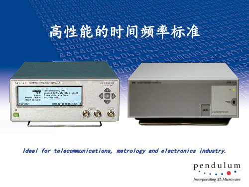
原子钟频率标准
中国 上海天文台
4×10-13 5×10-14 8×10-15 6×10-15 5×10-15
3×10-14 1.4×10⁻¹⁴/高斯
External signal
1.08×0.52×0.68
Ion pump
150
主要时间频率标准产品
• 铯钟: –Symmetricom
• 5071A • Cs4000 • CsIII • 4400 • 4500
第一光学 作用区 铯炉
外部受控振 荡器
原子束
光束
铯束管
激光器
第二光学作 用区
No Image
铯钟的工作原理(喷泉钟)(美国 NIST)
1. 由铯原子组成的气体,被引入 到时钟的真空室中,用激光减 慢了原子的运动速度并将其冷 却到接近绝对零度。
2. 两束垂直的激光轻轻地将这个 铯原子气球向上举起,穿过微 波腔,形成“喷泉”式的运动。
Cavity frequency switching
1.090.460.76
Ion pump
200
瑞士 T4science
1.5×10⁻¹³ 2×10-14 5×10-15 2×10-15 2×10-15 2×10-15
5×10-15 1×10-14/高斯
?
0.950.60.8
?
100
No Image
1×10-15 1×10-14/高斯
Cavity frequency switching
0.70.480.6
Getter pump
95
美国Symmetricom MHM- 2010
1.5×10⁻¹³ 5×10-14 1.3×10⁻¹⁴ 3.2×10⁻¹⁵ 3×10-15 3×10-15
原子钟——精选推荐

原⼦钟利⽤原⼦的⼀定共振频率⽽制造的精确度⾮常⾼的计时仪器。
是世界上已知最准确的时间测量和频率标准,也是国际时间和频率转换的基准,⽤来控制电视⼴播和全球定位系统。
现在⽤在原⼦钟⾥的元素有氢、铯、铷等,最好的铯原⼦钟精度可以达到每500万年相差1秒。
现在的世界标准时间,即是由原⼦钟报时的协调世界时。
环球⽹:由于格林尼治标准时间跟不上计算机时代的发展,今后⼈们可能将以原⼦钟标准时间为准。
原⼦钟以原⼦共振频率标准来计算及保持时间的准确,是世界上已知最准确的时间测量和频率标准,也是国际时间和频率转换的基准,⽤来控制电视⼴播和全球定位系统卫星的讯号。
原⼦钟⾥的元素有氢、铯(sè)、铷(rú)等。
最好的铯原⼦钟精度可以达到每500万年相差1秒。
这为天⽂、航海、宇宙航⾏提供了强有⼒的保障。
[1]原⼦钟直到20世纪20年代,最精确的时钟还是依赖于钟摆的有规则摆动。
取代它们的更为精确的时钟是基于⽯英晶体有规则振动⽽制造的,这种时钟的误差每天不⼤于千分之⼀秒。
即使如此精确,但它仍不能满⾜科学家们研究爱因斯坦引⼒论的需要。
根据爱因斯坦的理论,在引⼒场内,空间和时间都会弯曲。
因此,在珠穆朗玛峰顶部的⼀个时钟,⽐海平⾯处完全相同的⼀个时钟平均每天快三千万分之⼀秒。
所以精确测定时间的唯⼀办法只能是通过原⼦本⾝的微⼩振动来控制计时钟。
[2]1945年,哥伦⽐亚⼤学物理教授Isidor Rabi建议采⽤他在⼆⼗世纪三⼗年代开发的原⼦束磁共振法制造时钟。
1949年,国家标准局(NBS,现称美国国家标准技术协会,简称NIST)宣告开发了全球第⼀台将氨分⼦⽤做振荡源的原⼦钟;1952年,该机构宣告开发了第⼀台将铯原⼦⽤做振荡源的原⼦钟,即NBS-1。
1955年,英国国家物理实验室制造出了第⼀台可⽤做振荡源的铯束原⼦钟。
在其后的⼗年中,越来越多的先进时钟相继问世。
1967年,第13届度量衡⼤会在铯原⼦振荡技术的基础上制定了SI秒,从此,全球的计时系统不再以天⽂学技术为基础。
原子钟的基本原理及应用

原子钟的基本原理及应用1.原子钟的概念原子钟,是一种利用原子、分子能级差为基准信号来校准晶体振荡器或激光器频率,以使其输出标准频率信号的一种装置。
它利用原子能级跃迁产生的光信号,通过光电转化、信号处理后获得用来修正晶振或激光器频率的负反馈纠偏信号,使其输出稳恒振荡频率,这种输出频率可以用来精确计量时间。
根据采用的原子种类和技术手段的不同,原子钟可以分为很多种。
因为特定原子能级之间的能极差是很稳定的,所以原子钟的准确度很高,可以达到千万年仅差一秒或者更高的水平。
2.几种常见的原子钟随着物理学技术的发展,特别是与原子钟技术有关的原子、分子和光学物理方面的进步,极大地促进了原子钟技术的发展,人们研制出了不同种类的原子钟。
现代原子钟所采用的许多技术都与脉泽、激光以及后来的激光光谱学新领域的发展密不可分。
这些技术的发展导致原子和离子的激光冷却和囚禁技术的产生,很多新型原子钟也应运而生。
2.1冷原子喷泉钟冷原子喷泉钟主要有铯原子喷泉钟和铷原子喷泉钟两种,它们的工作原理相同,结构也大同小异。
喷泉原子钟工作时,冷原子云在电磁场以及重力的作用下沿喷泉管上下运动,以完成原子能级变化的检测,就像喷泉一样,所以取了一个形象的名字—喷泉钟。
2.2原子光钟原子光钟是一种作为参考标准的原子能级跃迁频率处于光频波段的原子钟。
原子光钟的工作原理与微波原子钟相似,除了跃迁频段不同之外,其频率发生器是稳频激光器而不是微波原子钟的晶体振荡器。
原子光钟用稳频激光器的脉冲去探测被激光冷却的工作物质(原子或离子),激励被冷却的工作物质发生跃迁,使用一个声光调制器(AOM)调节探测激光的频率,使它接近原子的共振频率,跃迁信息通过光电倍增管来检测,以原子跃迁产生的信号作为参考信号,并通过声光调制器和伺服系统调制探测激光的频率,使其锁定到原子的共振中心频率。
因为光频率比微波频率高大约5个量级,激光冷却可以把元素样品冷却到μK 量级的低温,从而使谱线具有很高的Q值,所以原子光钟可以达到很高的准确度和稳定度,频率稳定度可以达到10-17甚至10-18量级。
原子钟 秒稳定义
原子钟秒稳定义原子钟是一种利用原子的持续振荡来测量时间的仪器。
在原子钟中,原子的振荡频率非常稳定,可以用来定义时间的单位——秒。
因为原子钟的秒稳,所以可以用它来精确测量时间。
原子钟是利用原子的特性来测量时间的。
原子是构成物质的基本单位,每种原子都有自己独特的性质。
原子钟中常用的原子是铯(Cesium)和铷(Rubidium)原子。
这些原子具有稳定的振荡频率,在特定条件下能产生非常稳定的振荡信号。
原子钟的工作原理是通过利用原子的电磁性质来进行测量。
原子钟中的原子会受到恒定的微波辐射,这些微波辐射会使原子的电子从一个能级跃迁到另一个能级。
原子在不同能级之间跃迁时,会发射或吸收特定频率的光子。
原子钟通过测量这些光子的频率来确定时间的流逝。
原子钟的秒稳是指秒的定义是通过原子的振荡频率来确定的。
国际单位制中,秒被定义为铯原子的超精细能级跃迁所对应的振荡周期。
这个定义确保了秒的稳定性和准确性。
原子钟的秒稳意味着不同的原子钟测量出来的时间是一致的,可以互相校准。
原子钟的秒稳使得时间的测量变得非常准确。
相对于以前的机械钟或石英钟,原子钟具有更高的精度和稳定性。
原子钟的误差通常在纳秒或皮秒级别,可以满足现代科学研究和导航定位的需求。
原子钟的秒稳对于现代科学和技术的发展有着重要的意义。
在粒子物理学实验中,测量粒子的寿命或者相互作用时间需要非常精确的时间测量,原子钟提供了这样的准确性。
在卫星导航系统中,原子钟被用于测量信号的传播时间,以确定接收器的位置。
原子钟还被广泛应用于通信、金融和天文学等领域。
值得一提的是,原子钟的秒稳不仅仅是对时间的测量,还对时间的定义起到了关键的作用。
原子钟的秒稳是国际上统一的时间标准,各国的时间都基于原子钟的秒稳来确定。
这使得时间在全球范围内保持了一致性,方便了国际交流和合作。
原子钟的秒稳是利用原子的振荡频率来定义时间单位——秒的稳定性。
原子钟通过测量原子的电磁性质来确定时间的流逝,具有非常高的精度和稳定性。
原子钟 时频功能

原子钟的时频功能是指其提供高精度时间频率的能力。
原子钟利用原子能级跃迁的原理,以原子吸收或释放特定频率的光作为信号源,再通过反馈振荡系统,产生持续且高度稳定的振荡。
由于原子在不同能级间跃迁时,吸收或释放的能量是恒定的,因此原子钟产生的振荡频率具有极高的稳定性。
这种稳定性意味着原子钟能够提供非常精确的时间测量和频率标准,其频率误差和时间误差都极小。
此外,原子钟的时频功能还包括提供标准时间信号和标准频率信号。
这些信号可以用于各种需要高精度时间频率的应用,如全球卫星导航系统(GNSS)、电信、互联网、广播电视、军事等。
通过接收GNSS信号并与原子钟进行对比,可以进一步修正原子钟的误差,提高其精度。
总之,原子钟的时频功能是其最核心的功能之一,它可以提供高精度、高稳定性的时间频率信号,为各种应用提供可靠的时间和频率基准。
原子钟的精确值

原子钟的精确值介绍原子钟是一种利用原子的振动频率来测量时间的精确仪器。
它利用原子核或原子外层的电子在能级间跃迁的特性来产生稳定的振动信号。
原子钟的精确值极高,能够达到极高的时间稳定性和精确度,目前已经成为国际标准时间的主要依据。
原理原子钟的原理基于原子的量子特性,通过测量原子跃迁的频率来实现时间的计量。
常用的原子钟包括氢原子钟和铷原子钟。
氢原子钟氢原子钟利用氢原子的超精细能级跃迁来实现时间的测量。
氢原子的超精细能级间距非常稳定,因此可以用来作为时间的基准。
氢原子钟的工作原理可以简述如下:1. 首先,采用恒温腔来保持原子的温度稳定; 2. 然后,通过激光将氢原子激发到激发态; 3. 接着,在恢复态和激发态之间进行超精细能级间的跃迁; 4. 最后,通过计数原子跃迁的次数来测量时间。
铷原子钟铷原子钟利用铷原子的基态超精细能级跃迁来实现时间的测量。
铷原子的基态超精细能级间距也非常稳定,因此可以用来作为时间的基准。
铷原子钟的工作原理可以简述如下: 1. 首先,通过喷射铷原子到一个恒温腔中; 2. 然后,通过激光将铷原子激发到激发态; 3. 接着,在恢复态和激发态之间进行超精细能级间的跃迁;4. 最后,通过计数原子跃迁的次数来测量时间。
精确度和稳定性原子钟的精确度和稳定性是其最重要的特点之一。
原子钟的频率稳定度可以达到百万分之一或更高,这意味着在几百万年内,原子钟只会有几秒钟的误差。
这种高精确度和稳定性使原子钟成为许多领域重要的时间基准,如科学实验、导航系统、通信系统等。
应用原子钟的精确值在许多领域都有广泛的应用。
导航系统原子钟的高精确度和稳定性对全球导航系统(如GPS)至关重要。
导航系统需要准确的时间信息来确定物体的位置和速度,而原子钟提供了可靠的时间基准。
科学实验在科学实验中,时间的精确测量对于研究各种现象和性质至关重要。
例如,在物理学研究中,原子钟可以用于测量粒子的飞行时间,从而获得其速度和能量的信息。
原子钟定义的时间
原子钟定义的时间介绍原子钟是一种利用原子或分子振动的准确度极高的时钟。
它能够以极高的精确度测量时间,并被广泛用于科学实验、航空航天、导航、通信等领域。
本文将详细介绍原子钟的定义以及其与时间的关系。
什么是原子钟原子钟是一种基于原子或分子的振动频率来测量时间的装置。
它利用了自然界某些物质的稳定的振动行为,如铷原子和氢原子的振动。
原子钟通过稳定的原子或分子振荡来精确测量时间。
在原子钟中,原子或分子的振动周期非常稳定,可以达到非常高的精确度。
因此,原子钟可以被认为是时间的一个官方定义。
原子钟的工作原理原子钟的工作原理基于原子或分子的振动频率。
典型的原子钟利用原子中的电子能级跃迁产生的辐射,这些辐射的频率非常稳定。
常用的原子钟是基于铷原子或氢原子进行测量的。
1.铷原子钟的工作原理:–铷原子钟利用了铷原子在外加微波辐射下的能级跃迁。
当微波辐射的频率等于铷原子的电子能级跃迁频率时,铷原子会发生共振吸收。
–原子钟通过微波辐射的频率调节,使之刚好与铷原子的共振吸收频率相等。
通过不断调节微波辐射的频率,使之与铷原子的共振频率保持同步,就可以精确测量时间。
2.氢原子钟的工作原理:–氢原子钟是利用氢原子在外加精细结构常数辐射下的能级跃迁进行测量的。
–氢原子的能级结构比较复杂,由精细结构和超精细结构等组成。
两个不同能级之间的跃迁频率非常稳定,可用来作为时间的参考标准。
原子钟的时间定义原子钟测量的时间由国际单位制(SI)定义。
国际单位制中的时间单位是秒(second),它是通过原子钟定义的。
1.国际单位制秒的定义:–SI秒被定义为铯原子基态的两个能级之间跃迁辐射波长的9,192,631,770倍。
–这个定义基于铯原子的发射光谱特性,使得秒的精确度能够达到千分之一纳秒级别。
原子钟的重要性和应用原子钟在现代科技和社会中扮演着至关重要的角色,其应用广泛,以下是一些重要的应用领域:1.科学实验:–原子钟的高精确度对于科学实验是至关重要的。
原子钟影响因素
原子钟影响因素原子钟是一种利用原子物理性质来测量时间的设备,其精度非常高,能够达到每天误差不超过一秒。
原子钟的精确度和稳定性对于现代科学研究、通信、导航以及卫星定位等领域具有重要意义。
然而,原子钟的精确度受到多种因素的影响,下面将逐一介绍。
1. 原子的振荡频率:原子钟中使用的原子通常是铯、铷或氢原子等。
这些原子的振荡频率是原子钟精确计时的基础。
而原子的振荡频率受到原子核结构和电子轨道布局等因素的影响。
因此,原子钟的精确度和稳定性与所选用的原子种类和原子结构密切相关。
2. 温度变化:原子钟的精确度对温度变化非常敏感。
温度的变化会引起原子钟中原子的振荡频率发生变化,从而影响到计时的准确性。
为了减小温度变化对原子钟的影响,通常会对原子钟进行温度控制,使其保持在较为稳定的温度范围内。
3. 磁场干扰:磁场是原子钟的另一个影响因素。
磁场会对原子的能级结构产生影响,进而改变原子的振荡频率。
为了减小磁场对原子钟的干扰,通常会采取屏蔽措施,如使用磁屏蔽材料来减小外界磁场的干扰。
4. 外界干扰:原子钟的精确度还受到外界干扰的影响。
例如,机械振动、空气湿度、辐射等因素都可能对原子钟的准确性产生影响。
为了减小外界干扰,通常会将原子钟放置在稳定的环境中,并采取相应的防护措施。
5. 电磁辐射:原子钟中使用的原子通常是通过激光来操控和测量的。
而激光本身会产生电磁辐射,这种辐射也会影响原子钟的精确度。
为了减小电磁辐射对原子钟的影响,通常会采取屏蔽措施,如使用屏蔽材料或调整激光功率等。
6. 供电稳定性:原子钟对供电的稳定性要求非常高。
供电不稳定会导致原子钟中电子设备的工作不正常,从而影响到计时的准确性。
为了保证供电的稳定性,通常会采取多种措施,如使用稳定的电源、增加电源滤波器等。
7. 维护和校准:原子钟的精确度也与维护和校准的情况有关。
长时间的使用会导致原子钟的某些组件或部件出现老化或损坏,从而影响原子钟的精确度。
因此,定期的维护和校准对于保持原子钟的准确性至关重要。
- 1、下载文档前请自行甄别文档内容的完整性,平台不提供额外的编辑、内容补充、找答案等附加服务。
- 2、"仅部分预览"的文档,不可在线预览部分如存在完整性等问题,可反馈申请退款(可完整预览的文档不适用该条件!)。
- 3、如文档侵犯您的权益,请联系客服反馈,我们会尽快为您处理(人工客服工作时间:9:00-18:30)。
8130 Militarized Rubidium Frequency StandardOPERA TING MANUAL 8130A MILITARIZED RUBIDIUMFREQUENCYSTANDARD #14830-201, Rev C8130A Militarized Rubidium Frequency Standard TABLE OF CONTENTSCHAPTER ONEIntroduction/Product Overview4Purpose of Equipment5Options5Preparation for Shipment6Contact Information8CHAPTER TWOInstallation and Operation9Mounting9Basic Operation9Installation10Connections10Analog Monitors14Digital Monitors16Status Monitors17CHAPTER THREEFrequency Adjustments19CHAPTER FOURUse of RS-232 Terminal/Emulator21Introduction21Setup21User Interface Command Syntax24User Interface Commands25Software Description27Command Description28CHAPTER FIVESpecifications30INTRODUCTION/PRODUCT OVERVIEWThis Operating Manual contains procedures and descriptive information for proper installation and operation of the Symmetricom 8130A Militarized Rubidium Frequency Standard.OPERATING MANUAL SUMMARYThis Operating Manual is divided into the following chapters:A.CHAPTER ONE – INTRODUCTION/PRODUCT OVERVIEWThis chapter includes a general description of the Symmetricom 8130A and provides some basic product information.B.CHAPTER TWO – INSTALLATION AND OPERATIONDescribes initial inspection; installation and operation of the Symmetricom 8130A.C.CHAPTER THREE – FREQUENCY ADJUSTMENTSDescribes the procedures for the three means of frequency adjustment.C.CHAPTER FOUR – USE OF RS-232 TERMINAL/EMULATORDescribes command structure and rules for using the serial RS-232 port.D.CHAPTER FIVE – SPECIFICATIONSDescribes the detailed specifications for the 8130AChapter One8130A8130APURPOSE OF EQUIPMENTThe Symmetricom 8130A Militarized Rubidium Frequency Standard is an enhanced version of the pop-ular M-100 Rubidium Oscillator. This modern off-the-shelf militarized rubidium frequency standard isideal for use in tactical applications where shock, vibration, humidity and other environmental factorsare a challenge. The circuit boards are conformally coated for moisture resistance, and special pre-cautions are taken for improved shock and vibration hardening. Use of a filtered power/monitor con-nector minimizes EMI emissions and susceptibility. Designed for ease of integration into frequency andtime systems, the Symmetricom Model 8130A offers a smaller size militarized rubidium clock with aheritage of over 25 years of proven experience in the design, qualification and production of atomic fre-quency references.FEATURESSome of the important features of the Symmetricom 8130A are as follows:• Modern Militarized Design• COTS/SMD/PEM Devices for Lower Cost, Enhanced Features and Improved Performance• RS-232 Digital Control and Monitoring• Ruggedized High-Performance Rb Physics Package• Dual 5 or 10 MHz Sine or Square Wave Outputs• Separate Heater and Electronic Power Lines• +15 or +22 to 32 Vdc Power Options• Low Phase Noise Option• Internal Temperature Compensation OptionOPTIONSThe Symmetricom 8130A is available with several options, including operation from +15 Vdc condi-tioned power, 5 or 10 MHz sine or square wave outputs, low phase noise, and internal temperaturecompensation. Unless stated otherwise, this Operating Manual assumes the standard Symmetricom8130A configuration that operates from +22 to +32 Vdc, has 5 and 10MHz sine wave outputs with nor-mal phase noise, and no internal temperature compensation. All currently-available Symmetricom8130A configurations have a 15-pin male subminiature "D" power/monitor connector with the pinassignments shown in Table 2-2 in Chapter Two.8130APREPARATION FOR SHIPMENTTo turn off the Symmetricom 8130A prior to shipment, remove all connections from the front panel.Package the instrument in its original packing if possible. If the original packing materials are notavailable, pack in a reinforced cardboard carton using foam to take up any space inside the carton.Do not use foam popcorn or crushed paper for packing, and follow normal ESD preacuations.If the instrument is being returned to Symmetricom, contact the Service Department at (800) 938-9888to advise of the product return.TYPOGRAPHICAL AND OTHER CONVENTIONSThis Operating Manual uses the following conventions:Acronyms and Abbreviations – Terms are spelled out the first time they appear in thisOperating Manual. Thereafter, only the acronym or abbreviation is used. In addition, the glossarydefines the acronyms and abbreviations.Table 1-1 describes the typographical conventions that this Operating Manual uses todistinguish between the different types of information according to how they are used.TABLE 1-1. TYPOGRAPHICAL CONVENTIONS8130AWARNINGS, CAUTIONS, RECOMMENDATIONS, AND NOTESWarnings, Cautions, Recommendations, and Notes attract attention to essential or criticalinformation in this Operating Manual. The types of information included in each are explained asfollows:WARNING …All warnings have this symbol. Do not disregard warnings. They are installation,operation, or maintenance procedures, practices, or statements that if not strictlyobserved, may result in personal injury or loss of life.ELECTRICAL SHOCK HAZARD …All electrical shock hazard warnings have this symbol. To avoid serious personal injuryor death, do not disregard electrical shock hazard warnings. They are installation,operation, or maintenance procedures, practices, or statements that if not strictlyobserved, may result in personal injury or loss of life.CAUTION …All cautions have this symbol. Do not disregard cautions. They are installation, operation,or maintenance procedures, practices, conditions, or statements that if not strictlyobserved, may result in damage to or destruction of equipment or may cause a long-termhealth hazard.CAUTION …All Electrostatic Discharge (ESD) cautions have this symbol. They are installation,operation, or maintenance procedures, practices, conditions, or statements that if notstrictly observed, may result in electrostatic discharge damage to, or destruction of,static sensitive components of the equipment.RECOMMENDATION …All recommendations have this symbol. Recommendations indicate manufacturer-testedmethods or known functionality. They contain installation, operation, or maintenanceprocedures, practices, conditions, or statements that provide you with importantinformation for optimum performance results.NOTE …All notes have this symbol. Notes contain installation, operation, or maintenanceprocedures, practices, conditions, or statements that alert you to important informationwhich may make your task easier or increase your understanding.8130AWHERE TO FIND ANSWERS TO PRODUCT AND DOCUMENT QUESTIONSIf you believe that this product is not performing as expected, or if you have comments aboutthis Operating Manual, please contact your Symmetricom representative or sales officeWe appreciate your suggestions on ways to improve this Operating Manual. Please mark or writeyour suggestions on a copy of the page and mail or fax it to …Symmetricom – Timing, Test & Measurement3750 Westwind BoulevardSanta Rosa, CA 95403US Toll Free:1-888-367-7966Phone:+1-707-528-1230Fax:+1-707-527-6640E-mail:ttmsales@Thank you for providing the information.NOTE …Symmetricom offers a number of applicable training courses designed to enhanceproduct usability. Contact your Symmetricom representative or sales office for acomplete list of courses and outlines.8130A Chapter TwoINSTALLATION AND OPERATIONMOUNTINGThe 8130A is designed to be mounted on its bottom plate, using 4 tapped #8 holes, as shown in Figure2-1. This mounting surface also serves as a means of heat transfer. The unit is specified for operationto +68ºC baseplate temperature, and the corresponding upper ambient temperature limit will dependon the thermal properties of the 8130A mounting arrangement. The use of a thermal pad between thebottom of the 8130A and its heat sink is recommended. Access to the front of the unit is required forpower and RF connections.FIGURE 2-1. MODEL 8130A OUTLINE DRAWING ArrayBASIC OPERATION8130A operation requires only the application of DC power. After a short warm-up time, high stability 5or 10 MHz standard frequency outputs are available. The power supply for the unit must be capableof supplying +22 to +32 Vdc (+28 Vdc nominal) at 1.5 A.8130AINSTALLATIONInstallation of the 8130A requires that the unit be mounted as described above, and connected to thehost system as described below.CONNECTIONSThe 8130A has three connectors, a 15-pin male subminiature "D" power/monitor connector (J1) andtwo SMA receptacle RF output connectors (J2 and J3), as shown in Figure 2-2. Detailed informationabout these connectors is shown in Tables 2-1 and 2-2.FIGURE 2-2. SYMMETRICOM 8130A CONNECTIONS8130A TABLE 2-1. SYMMETRICOM 8130A CONNECTOR TYPESTABLE 2-2. SYMMETRICOM 8130A CONNECTOR PINOUTS8130A NOTES …[1]The electronic and heater power leads are not common.[2]The electronic and heater voltage is normally +22 to +32 Vdc, (+28 Vdc nominal), butmay be +15 ±0.5 Vdc as an option.[3]The heater monitors are voltages proportional to the heater currents.[4]This pin may be used instead for the optional external C-field voltage.[5]The DC returns are common, apply to all signals, and are connected to thechassis ground.The heater and electronic returns may be separated as an option.[6]The TX and RX designations are from the perspective of the Symmetricom 8130A.Standard bipolar RS-232 levels are used.[7]The PLL monitor applies to the low noise OCVCXO option.[8]These pins may be used for other options.[9] Lock = 0V, unlock = +5V, open collector and reverse logic optional.J1 POWER, MONITOR AND CONTROL CONNECTIONSThe 8130A J1 power/monitor/control connections are shown in Table 2-2. The only J1 connectionsnecessary for operation are those to the external DC power supply (pins 1, 7, 8 and 9). The other con-nections are for optional monitoring and control purposes.POWER INPUTThe 8130A requires a power supply voltage between +22 and +32 Vdc. Pins 1 and 7 (the heater andelectronic power connections respectively) are normally connected together externally, and should beconnected to the positive lead of a 28 V nominal DC power supply. Pins 8 and 9 (the DC return andcase ground) are connected together internally, and either or (preferable) both should be connectedto the negative lead of the power supply. No internal ground (case) isolation is provided, although thiscould be accomplished externally by mounting the unit on an electrical insulator (with considerationgiven to the thermal resistance added thereby). Reverse polarity protection is provided by a seriesdiode, and transient over-voltage protection is provided by a 33-47 V zener diode. The power sourceshould by current-limited or fused. The maximum supply current is 1.3 A at +32 Vdc during warm-up.Under steady-state conditions (after the physics package ovens are in control), the power consump-tion will depend inversely on the baseplate temperature. At constant baseplate temperature, becausethe oven power is constant, and an internal DC/DC converter conditions the electronic power, the totalpower is essentially independent of supply voltage. A skeleton schematic of the DC input circuit isshown in Figure 2-3.8130A FIGURE 2-3. POWER INTERFACE8130AANALOG MONITORSThe 8130A has eight analog monitors that may be used to determine its status. These monitors aredescribed in Table 2-3.TABLE 2-3. ANALOG MONITORSWhile it is not necessary to do anything with these monitors, it is recommended that, at a minimum,the Lock (BITE) signal be used to indicate that the unit is functioning properly. A skeleton schematic ofthe analog and status monitors is shown in Figure 2-4a.8130A FIGURE 2-4A. ANALOG AND STATUS MONITORS8130ADIGITAL MONITORSThe digital monitors provide a 2-byte (4 hex character) number with a 0 to 4095 count range thatcorresponds to a value of 0 to 2.048 volts. This value can be scaled as shown in the table below toprovide the actual monitor reading These monitors are produced by a 12-bit analog-to-digital converterdata acquisition system and are described in Table 2-4.TABLE 2-4. DIGITAL MONITORSIn addition, the unit has a temperature monitor that indicates the temperature on the motherboard. Itis representative of the internal ambient temperature and is used as the basis for the internal temper-ature compensation.It is not necessary to do anything with these monitors.8130ASTATUS MONITORSThe 8130A has five digital status monitors that may be used to determine its status, as described inTable 2-5.TABLE 2-5. STATUS MONITORSC-FIELD VOLTAGEThe external C-field voltage input can be used to make analog frequency adjustments (such as lockingthe Symmetricom 8130A to a GPS time and frequency reference). This control characteristic is shownin Figure 2-5.FIGURE 2-5. SYMMETRICOM 8130A C-FIELD CHARACTERISTIC8130ARS-232 INTERFACEThe RS-232 interface can be used be used for control and monitoring purposes. Its main function is tomake frequency adjustments. See Chapter Four for detailed information about using the RS-232 userinterface through the Windows Terminal Emulator.FUNCTIONAL TEST SETUPA typical 8130A functional test setup is shown in Figure 2-6. Connections to the 8130A power, monitorand control leads can be facilitated with a breakout box. This device connects between an 8130Aunder test, its power supply, a PC serial port, an oscilloscope and a digital voltmeter. The PC can usea terminal emulation or other program to communicate with the 8130A via its RS-232 interface. Inaddition, the oscilloscope can observe the Rb signal, and the digital voltmeter can measure the vari-ous RFS monitors, and its heater and electronic DC supply currents via the 4-terminal current sensingresistors.FIGURE 2-6. 8130A FUNCTIONAL TEST SETUP8130A Chapter ThreeFREQUENCY ADJUSTMENTSThe Symmetricom 8130A has three means of frequency adjustment:1.RS-232 user interface2.Analog C-field voltage3.C-Field circuit resistanceThe preferred frequency adjustment method is via the RS-232 user interface using a terminal emulatoror other program that implements the following (upper-case ASCII) commands:F Read frequencyI Increment frequencyD Decrement frequencyW Write frequencyX Store frequencyThe F and W commands each transmit or receive 32 bits (4-bytes) of tuning data as 8 ASCII hex char-acters to or from the external terminal. The I and D commands make up/down tuning adjustments insteps of about 3.41x10⁻¹³. The X command causes the current tuning data to be permanently stored inthe EEPROM memory within the Symmetricom 8130A.The analog C-field interface implements a traditional means of frequency adjustment whereby thevalue of the internal physics package DC magnetic bias field can be varied. In the Symmetricom8130A, this adjustment is deliberately limited to a range of about ±5x10⁻¹⁰to reduce sensitivity to exter-nal magnetic fields. Coarse frequency adjustments must be made with the self-contained digital fre-quency synthesizer. Fine analog adjustments are supported for applications such as locking the unitto an external reference or GPS receiver.The Symmetricom 8130A C-field tuning characteristic is:Relative Frequency, pp1010 = [(V ext+ 6.9)2• 4.43x10⁻²] – 8.43which is plotted in Figure 3-1 below.The Symmetricom 8130A does not have an internal frequency adjustment potentiometer. If a meansfor mechanical frequency adjustment is needed, it can be implemented by connecting a variableresistance between the J1 Pin 12 C-Field connection and ground. Because of the limited adjustmentrange, this method of frequency adjustment is intended only to supplement, not replace, the digitalinterface.8130A If not used for voltage or resistance tuning, the C-Field pin is normally not connected. While it can beused to monitor the internal C-field reference voltage, for best stability, it should not be externallyloaded.FIGURE 3-1. C-FIELD CHARACTERISTIC8130A Chapter FourUSE OF RS-232 TERMINAL/EMULATORINTRODUCTIONThe most basic way to communicate with a Symmetricom 8130A Rubidium Frequency Standard via itsuser interface is by means of an RS-232 terminal or terminal emulator. This can be useful to test theinterface, to perform simple operations, or to control the unit automatically. For example, sending the"N" command will provide the serial number of the unit, and sending the A00 01 command will turn onthe internal temperature compensation. The screen of a PC running the Microsoft Terminal programand connected to an 8130A is shown in Figure 4-1 below.FIGURE 4-1. MICROSOFT TERMINAL PROGRAMSETUPBefore the 8130A RS-232 interface can be used, the unit must be connected via a custom cable to theserial port of an RS-232 terminal (or a PC running a terminal emulator program). Three wires arerequired (in addition to those supplying power to the unit and providing other control and monitoringfunctions), as shown below:Signal Name 8130A PC Serial Port& Abbreviation J2 Pin 9-Pin25-PinTransmit Data TD1132Receive Data RD10 23Signal Ground SG8 & 9578130A Note that the signal names are from the perspective of the PC. The 8130A interface uses standard ±12VRS-232 signal levels and requires the following communications port settings:Baud Rate= 9600# Data Bits= 8# Stop Bits= 1Parity= NoneFlow Control= NoneThese parameters must be set, and the correct COM port must be selected, as shown for the MicrosoftTerminal program in Figure 4-2 below. The connection may be tested by issuing a "#" command, whichshould elicit a response of "8130A".FIGURE 4-2. COMMUNICATIONS SETTINGS8130A WARNING …It is possible to impair or even stop the operation of a 8130A Rubidium FrequencyStandard by loading incorrect parameters into it via the RS-232 user interface. It isstrongly recommended that the original hex values of the frequency and modulation ratebe read with the F and M commands (see Figure B.2.1), and those values recordedbefore making any changes. It is particularly important not to permanently store incor-rect values into the 8130A EEPROM memory with the X command. If necessary, the fol-lowing default values can be used to restore operation of an improperly programmed8130A Rubidium Frequency Standard:Parameter Hex Value Write CommandHigh Freq44 08 E0 00 WB0E8064400E00844Low Freq44 06 E8 B0Mod Rate7EIt could also become necessary to restore all the temperature compensation data to itsdefault hex value of 00.Under no circumstances should the modulation rate be changed.8130A TABLE 4-1. USER INTERFACE COMMAND SYNTAXSee notes on the following page.8130A NOTES …1. The [ ] brackets indicate data sent to unit – they are not actual characters.2. All commands must be upper case.3. All command sequences end with LF/CR ("\n\r").4. All invalid commands return the error code E.5. All data bytes are formatted as pairs of hex characters.6. Spaces in the command sequences must be observed as shown.7. The total # of chars does not include LF/CR after command.8. The frequency data is transmitted as low freq, high freq, LS bytes first.9. The status bits and monitor channels are as follows:Bit Status Chan Monitor0N/A0Light1Lock1VCXO2Ovens2Lamp Oven3Light3Cavity Oven4PLL4Signal5O/P5+15V Supply6N/A6PLL7N/A7SRD Bias10. The * command should not be used to change the S/N of a unit.USER INTERFACE COMMANDSThe Symmetricom 8130A user interface can be activated to read status, monitor or frequency param-eters by sending one of the commands listed in Table 4-2 as a single of ASCII character followed by acarriage return character. The 8130A will respond by sending 2-8 ASCII hex (0-F) characters repre-senting the value of the requested parameter, followed by a carriage return. In all cases, the first hexcharacter sent or received represents the most significant 4 bits of the most significant byte, and thecharacter sequence continues in descending order toward the least significant 4 bits of the least sig-nificant byte. Some of these commands (such as loading the S/N and temperature compensation data)are reserved for factory calibration and test purposes. The user interface can also be used to writetuning data by sending the W command as a pair of ASCII characters, 8 ASCII hex characters repre-senting the nominal frequency value, and a carriage return character. The unit will make no response,but the new frequency can be verified with the "F" command. Similarly, the optional O/P DDS can bewritten and read with the "P" and "O" commands. Temperature compensation data are written andread with the "T" and "A" commands respectively. These are one-byte incremental corrections that areadded to the nominal four-byte DDS frequency word. With the PIC16F628 microcontroller, correctionvalues are stored at ² 1.28ºC increments from -40ºC to +80ºC with a resolution of ² 3.41x10⁻¹³.Table 4-2 is a complete list of commands for the Symmetricom 8130A.8130A TABLE 4-2. RS-232 USER INTERFACE COMMANDS8130A NOTES …1.By sending [W] tuning commands that increment or decrement only one of thehigh and low DDS words, it is possible to adjust the frequency of the 8130A in stepsof about 3.41x10⁻¹³. The resulting change in the modulation deviation is negligible(4 mHz).2.The sense of the [I] and [D] commands corresponds to the RFS O/P frequency; theDDS frequency changes in the same direction. The high and low DDS hex words areincremented and decremented alternately, providing a resolution of 3.41x10-13.3.Send [<] command before any other command sequence to stop timer interruptsthat can interfere with external RS-232 communications, and [>] command afterwardsto re-enable elapsed time and (optional) temperature compensation. Two [<]commands, or checking for a LF/CR response, are recommended to avoid possibilityof one occurring during timer isr.SOFTWARE DESCRIPTIONThe 8130A user interface responds to the ASCII character commands shown in the preceding table. Most ofthese commands are processed only by the processor on the motherboard, but the [I], [D], [W] and [R] commandsalso involve the processor on the RF board via the PBus internal communications bus. The motherboard softwarecomprises two sections, a main loop that waits for and processes user commands, and a timer interrupt serviceroutine that accumulates elapsed time and performs optional temperature compensation. The timer interruptsare automatically disabled while the software is processing user commands. But because it is possible for theunit to fail to respond to a user interface command while it is processing a timer interrupt, it is necessary that thetimer interrupts be manually disabled at the start of a command sequence by the [<] command. Because thatcommand itself could be missed, sending two such commands is recommended. It is also necessary that the [>]command be sent at the end of a command sequence to re-enable the timer interrupts.All non-volatile data is stored in the EEPROM of the motherboard processor. These data include S/N, frequency,modulation rate, # turnons, elapsed time, TC flag and TC values. The model # is hard-coded into the software.The stored frequency is the uncompensated value at +25ºC. TC values can be written into the unit using the [A]command. When activated by the [A00 01] command sequence, TC corrections are applied to the DDS frequencyat 20-second intervals.The [W] command enters frequency data into working memory, but does not store it in EEPROM. The new fre-quency will be lost if the unit is shut off, or if the TC flag is turned off. Subsequent TC corrections are appliedincrementally and remain applicable after a frequency load. The uncompensated +25ºC frequency value is readfrom EEPROM when the TC corrections are deactivated. The [X] command stores the current frequency data inEEPROM. The unit may be syntonized by using the [W] command to zero the frequency error, followed by the [X]command to save it in EEPROM. That should be done only at +25ºC unless the TC flag is on.8130A TABLE 4-3. COMMAND DESCRIPTIONSFIGURE 4-3. FREQUENCY SYNTONIZATION8130A The elapsed time indication is a 3-byte count of minutes having a range of about 32 years. The weightof one count for the three bytes is about 1 minute, 4.3 hours and 46 days. More exactly, the minutecount is based on 60 1-second counts having an actual rate of 20 MHz divided by 4*256*256*76, or1.0038677015 Hz. Thus the minute count is high by about 0.39% (334 seconds/day). That bias can becorrected by scaling the elapsed time reading. The exact LSB weight is 0.9961472 minute, and thewhole elapsed time count can be converted to hours by dividing it by 60.2320621. Two other factorstend to bias the elapsed time low, truncation of the LS byte and loss of counts during user commandprocessing. Only the two most significant bytes are stored in EEPROM, so, on average, about 128 min-utes are lost when a unit is turned off. This error can be corrected for approximately by adding 2hours for each turn-on that is recorded for the unit. The count loss due to command processing issmall in any normal operating scenario.8130A Chapter FiveSPECIFICATIONSNOTE …ELECTRICAL SPECIFICATIONSOutput Frequency/Waveform: 5 or 10 MHz sine or square waveOutput Level (2 outputs):+7.0 ±1.5 dBm (each output)0.5 Vrms nominal into 50Output Impedance:50 nominal at 5 or 10 MHzPhase Noise SB Freq Standard Low Noise Low Noise(SSB),10 MHz10 MHz 5 MHz£(f), dBc/Hz: 1 Hz-70 dBc/Hz-85 dBc/Hz-95 dBc/Hz10 Hz-90 dBc/Hz-115 dBc/Hz-125 dBc/Hz100 Hz-120 dBc/Hz-140 dBc/Hz-140 dBc/Hz1 kHz-135 dBc/Hz-150 dBc/Hz-150 dBc/Hz10 kHz-140 dBc/Hz-150 dBc/Hz-150 dBc/Hz100 kHz-140 dBc/Hz-150 dBc/Hz-150 dBc/HzSpectral Purity:Harmonics:<-30 dBcNon-Harmonics:<-80 dBcAging:Monthly (after 1 month):<3 E-11/month10 Years<1 E-9Frequency Accuracyat Shipment 1 E-11 (@ +25° C)Frequency Retrace<5 E-11Short Term Stability Standard Low Noise10 MHz10 MHzt = 1 sec<1 E-11<3E-11t = 10 sec<3 E-12<3E-11t = 100 sec<1 E-12<1E-12Frequency Control:Analog Freq. Adj. Range 1 E-9Digital Freq. Adj. Resolution 3.4 E-13Warm-up:AT –40° C At 25° CTime to Lock:<14 min<8 minTime to 5 E-10:<17 min<10 minMax. Input (Watts) @ 28 V<35 Watts<35 Watts。
