1808SAZAT3A中文资料
ARTISAN

390National Instruments • Tel: (800) 433-3488•Fax: (512) 683-9300•***********•C o u n t e r /T i m e r A c c e s s o r i e s a n d C a b l e sD a t a A c q u i s i t i o n a n d S i g n a l C o n d i t i o n i n gAccessory and Cable Selection ProcessStep 1.Select your counter/timer device from Tables 1 and 2.Step ing Tables 1 and 2 as a guide,determine which accessories are appropriate for that device.Select an accessory using Table 3 as reference.Step ing Tables 1 and 2,determine the appropriate cable solution for your selected counter/timer device and accessory.AccessoriesBNC-2121 (See Figure 1)Connector block with BNC and spring terminal connections for easy connection of I/O signals to counter/timer devices.The BNC-2121 offers spring terminals,as well as eight dedicated and six user-defined BNC connectors,which provide access to all I/O signals.This connector block is also a full-featured test accessory that provides pulse-train,trigger,and quadrature encoder signals.For the connections,refer to the BNC-2121 user guide at /manualsBNC-2121......................................................................................................778289-01Dimensions – 26.7 by 11.2 by 5.5 cm (8.0 by 4.4 by 2.2 in.)CA-1000 (See Figure 2)Configurable signal connectivity solution for connecting counter/timers to different types of standard I/O connectors.You can also incorporate switches and LED indicators.You can place the CA-1000 under a laptop PC,on a benchtop,or in a 19 in.rack.CA-1000......................................................................................................See page 351Dimensions – 30.7 by 25.4 by 4.3 cm (12.1 by 10 by 1.7 in.)Counter/Timer Accessories and CablesFigure 2. CA-1000 Configurable Signal Conditioning SolutionFigure 1. BNC-2121 Connector BlockAccessory DescriptionPage BNC-2121BNC connector block with built-in test features390CA-1000Configurable connector accessory 390SCB-68Shielded screw connector block 391TB-2715Front-mount terminal block for PXI-660x391TBX-68DIN-rail connector block 391CB-68LP Low-cost screw connector block 391CB-68LPR Low-cost screw connector block 391Table 1. Accessories and Cables for PXI-6601 and PCI-6602Table 2. Accessories and Cables for PXI-6602 and PXI-6608Table 3. Overview of AccessoriesPCI-6601, PCI-6602AccessoriesCables BNC-2121, CA-1000, SCB-68,–TBX-68, CB-68LP , and CB-68LPR R6868 or SH68-68-D1TB-2715N/APXI-6602, PXI-6608AccessoriesCables BNC-2121, CA-1000, SCB-68,–TBX-68, CB-68LP , and CB-68LPR R6868 or SH68-68-D1TB-2715Connects directly to the deviceCounter/Timer Accessories and CablesSCB-68 Shielded I/O Connector Block (See Figure 3)Shielded I/O connector block for easy connection of I/O signals to the counter/timer devices.T he screw terminals are housed in a metal enclosure for protection from noise bined with a shielded cable,the SCB-68 provides rugged,very low-noise signal termination.T he SCB-68 also includes two general-purpose breadboard areas.SCB-68..............................................................................................................776844-01Dimensions – 19.5 by 15.2 by 4.5 cm (7.7 by 6.0 by 1.8 in)TB-2715 Terminal Block (See Figure 4)With the T B-2715 terminal block for PXI counter/timer devices,you can connect signals directly without additional cables.Screw terminals provide easy connection of I/O signals.The TB-2715 latches to the front of your PXI module with locking screws and provides strain relief.TB-2715............................................................................................................778242-01Dimensions – 8.43 by 10.41 by 2.03 cm (3.32 by 4.1 by 0.8 in.)TBX-68 I/O Connector Block with DIN-Rail Mounting (See Figure 5)Termination accessory with 68 screw terminals for easy connection of field I/O signals to the counter/timer devices.The TBX-68 is mounted in a protective plastic base with hardware for mounting on a standard DIN rail.TBX-68..............................................................................................................777141-01Dimensions – 12.50 by 10.74 cm (4.92 by 4.23 in.)CB-68LP and CB-68LPR I/O Connector Blocks (See Figure 6)Low-cost termination accessories with 68 screw terminals for easy connection of field I/O signals to the counter/timer devices.The connector blocks include standoffs for use on a desktop or mounting in a custom panel.T he CB-68LP has a vertically mounted 68-pin connector.The CB-68LPR has a right-angle mounted connector for use with with the CA-1000.CB-68LP............................................................................................................777145-01Dimensions – 14.35 by 10.74 cm (5.65 by 4.23 in.)CB-68LPR ........................................................................................................777145-02Dimensions – 7.62 by 16.19 cm (3.00 by 6.36 in.)391National Instruments • Tel: (800) 433-3488•Fax: (512) 683-9300•***********•Counter/Timer Accessories and CablesData Acquisition andSignal ConditioningFigure 6. CB-68LP and CB-68LPR I/O Connector BlocksFigure 5. TBX-68 I/O Connector BlockFigure 4. TB-2715 I/O Terminal BlockFigure 3. SCB-68 Shielded I/O Connector Block392National Instruments • Tel: (800) 433-3488•Fax: (512) 683-9300•***********•C o u n t e r /T i m e r A c c e s s o r i e s a n d C a b l e sD a t a A c q u i s i t i o n a n d S i g n a l C o n d i t i o n i n gCablesRTSI Bus Cables (See Figures 7 and 8)Use RT SI bus cables to connect timing and synchronization signals among measurement,vision,motion,and CAN boards for PCI.For systems using long and short boards,order the extended RTSI cable.2 boards ..........................................................................................................776249-023 boards ..........................................................................................................776249-034 boards ..........................................................................................................776249-045 boards ..........................................................................................................776249-05Extended,5 boards ........................................................................................777562-05SH68-68-D1 Shielded Cable (See Figure 9)Shielded 68-conductor cable terminated with two 68-pin female 0.050 series D-type connectors.This cable connects counter/timer devices to accessories.1 m..................................................................................................................183432-012 m..................................................................................................................183432-02R6868 Ribbon I/O Cable (See Figure 10)68-conductor flat ribbon cable terminated with two 68-pin e this cable to connect the NI PCI-6601 to an accessory.For signal integrity with high-frequency signals,use the SH68-68-D1 with the NI 6602 and NI 6608.1 m..................................................................................................................182482-01Custom Connectivity Components68-Pin Custom Cable Connector/Backshell Kit (See Figure 11)68-pin female mating custom cable kit for use in making custom 68-conductor cables.Solder-cup contacts are available for soldering of cable wires to the connector.68-pin custom cable kit ................................................................................776832-01PCB Mounting ConnectorsPrinted circuit board (PCB) connectors for use in building custom accessories that connect to 68-conductor shielded and ribbon cables.Two connectors are available,one for right-angle and one for vertical mounting onto a PCB.68-pin,male,right-angle mounting..............................................................777600-0168-pin,male,vertical mounting....................................................................777601-01Counter/Timer Accessories and CablesFigure 10. R6868 Ribbon I/O CableFigure 9. SH68-68-D1 Shielded CableFigure 8. Extended RTSI Bus CableFigure 7. RTSI Bus CableFigure 11. 68-Pin Custom Cable Kit。
AZ AQUATAR家族产品系列介绍说明书

9F3C
1F3C
PFOS
CF2 CF2 CF2 SO3OH
CF2 CF2 CF2
PFOA
CF2 F3C
CF2 CF2 CF2
C8 Telomer
CF2 CF2 CF2 CH2CH2OH CF2 CF2 CF2 CF2
CF2
CF2
CF2
COOH
AZ Electronic Materials Confidential
(1.44/1.48/1.56)
(1.40/1.43/1.45)
AQUATAR-3S (1.42/1.44/1.49)
PFOS
AQUATAR-6 (1.40/1.43/1.45)
Fluoro Polymer
AQUATAR-8A (1.41/1.45/1.52)
AQUATAR-8B
for KrF “N” resist
4
AZ, the AZ logo, BARLi, Aquatar, nLOF, Kwik Strip, Klebosol, and S5pinfil are
registered trademarks and AX, DX, HERB, HiR, MiR, NCD, PLP, Signiflow,
SWG, and TARP are trademarks of AZ Electronic Materials.
SWG, and TARP are trademarks of AZ Electronic Materials.
2.4 Resist swing reduction effect in 365nm application
Substrate TARC Develop
: Silicon with HMDS(90C/60s) : 64nm FT, NO PAB : AZ 300MIF(2.38%) , puddle 60s
JMT1808R 微控制器用户手册说明书

JMT1808R MCU用户手册江苏宏云技术有限公司*************Dec. 2016 V1.12微控制器JMT1808R 1产品概述 (20)1.1功能描述 (20)1.2主要特性 (20)1.3框图 (22)1.4应用范围 (22)1.5引脚配置 (23)1.5.1 LQFP48L引脚图 (23)1.5.2 LQFP32L引脚图 (24)1.5.3 QFN32L引脚图 (25)1.5.4 TSSOP28L引脚图 (26)1.5.5 引脚说明 (27)2电源管理(PMU) (30)2.1概述 (30)2.2低功耗控制 (30)2.2.1 降低系统时钟频率 (31)2.2.2 外设时钟门控 (32)2.2.3 关闭模拟模块 (32)2.2.4 四种低功耗模式 (32)2.2.5 OSC开关说明 (34)2.3寄存器 (34)2.3.1 低功耗控制寄存器(PMUCTR) [0xA1] (35)3时钟复位管理(CRM) (36)3.1时钟管理 (36)3.1.1 概述 (36)3.1.2 框图 (36)3.1.3 功能描述 (37)3.1.4 寄存器描述 (42)3.2复位管理 (52)3.2.1 概述 (52)3.2.2 框图 (53)3.2.3 功能描述 (53)3.2.4 寄存器 (56)1微控制器JMT1808R4JMT51 MCU核 (61)4.1概述 (61)4.2指令集 (61)5JMT018 DSP核 (67)5.1概述 (67)5.1.1 框图 (67)5.1.2 系统总线 (67)5.1.3 运算单元(ALU) (68)5.1.4 乘累加单元(MAC) (68)5.1.5 除法单元(DIV) (68)5.1.6 硬件循环(HW loop) (69)5.1.7 数据传输 (69)5.1.8 存储单元 (69)5.2指令集 (69)5.2.1 数据传输指令 (69)5.2.2 算术运算指令 (71)5.2.3 移位运算指令 (72)5.2.4 逻辑运算指令 (73)5.2.5 乘法运算指令 (73)5.2.6 并行运算指令 (74)5.2.7 程序控制指令 (77)5.3数据运算器 (78)5.3.1 通用寄存器 (78)5.3.2 累加器A (79)5.3.3 乘法 (83)5.3.4 乘加运算 (84)5.3.5 加减运算 (86)5.3.6 移位运算 (86)5.3.7 四舍五入方法 (87)5.4DSP存储空间 (87)5.4.1 数据存储空间 (87)5.4.2 程序存储空间 (88)5.5DSP工作配置 (89)2微控制器JMT1808R 5.6DSP代码生成与下载 (89)5.6.1 DSP代码生成 (89)5.6.2 DSP代码下载 (89)5.7DSP内部寄存器 (90)5.7.1 DSP通用寄存器R0 (90)5.7.2 DSP通用寄存器R1 (91)5.7.3 DSP通用寄存器R2 (91)5.7.4 DSP通用寄存器R3 (91)5.7.5 DSP通用寄存器R4 (91)5.7.6 DSP通用寄存器R5 (91)5.7.7 DSP通用寄存器R6 (91)5.7.8 DSP通用寄存器R7 (91)5.7.9 X数据空间指针寄存器DP0 (92)5.7.10 Y数据空间指针寄存器DP1 (92)5.7.11 DSP程序地址指针寄存器PC (92)5.7.12 乘法及乘加结果寄存器A (92)5.7.13 LINK寄存器 (92)5.7.14 状态寄存器PSR (92)5.7.15 模式寄存器PMR (93)5.7.16 硬件循环次数寄存器LOOP (93)5.7.17 硬件循环指令个数寄存器LIR (94)5.8JMT51访问DSP寄存器 (94)5.8.1 DSP配置寄存器(DSP_CFG) [0xD4] (95)5.8.2 DSP运行状态寄存器(DSP_STA) [0xD1] (95)5.8.3 PC寄存器低字节(DSP_PCL) [0xD2] (96)5.8.4 PC寄存器高字节(DSP_PCH) [0xD3] (96)5.8.5 R0寄存器低字节(DSP_R0L) [0xD9] (96)5.8.6 R0寄存器高字节(DSP_R0H) [0xDA] (96)5.8.7 R1寄存器低字节(DSP_R1L) [0xDB] (96)5.8.8 R1寄存器高字节(DSP_R1H) [0xDC] (97)5.8.9 R2寄存器低字节(DSP_R2L) [0xDD] (97)5.8.10 R2寄存器高字节(DSP_R2H) [0xDE] (97)5.8.11 R3寄存器低字节(DSP_R3L) [0xDF] (97)5.8.12 R3寄存器高字节(DSP_R3H) [0xE1] (97)5.8.13 R4寄存器低字节(DSP_R4L) [0xE2] (97)3微控制器JMT1808R45.8.14 R4寄存器高字节(DSP_R4H) [0xE3] (97)5.8.15 R5寄存器低字节(DSP_R5L) [0xE4] (98)5.8.16 R5寄存器高字节(DSP_R5H) [0xE5] (98)5.8.17 R6寄存器低字节(DSP_R6L) [0xE6] (98)5.8.18 R6寄存器高字节(DSP_R6H) [0xE7] (98)5.8.19 R7寄存器低字节(DSP_R7L) [0xE9] (98)5.8.20 R7寄存器高字节(DSP_R7H) [0xEA] (98)5.8.21 DP0寄存器低字节(DSP_DP0L) [0xEB] (98)5.8.22 DP0寄存器高字节(DSP_DP0H) [0xEC] (99)5.8.23 DP1寄存器低字节(DSP_DP1L) [0xED] (99)5.8.24 DP1寄存器高字节(DSP_DP1H) [0xEE] (99)5.8.25 A寄存器7~0比特(DSP_A0L) [0xEF] (99)5.8.26 A寄存器15~8比特(DSP_A0H) [0xF1] (99)5.8.27 A寄存器23~16比特(DSP_A1L) [0xF2] (99)5.8.28 A寄存器31~24比特(DSP_A1H) [0xF3] (99)5.8.29 A寄存器39~32比特(DSP_A2) [0xF4] (100)5.8.30 LNKR寄存器低字节(DSP_LNKRL) [0xF5] (100)5.8.31 LNKR寄存器高字节(DSP_LNKRH) [0xF6] (100)5.8.32 PSR寄存器低字节(DSP_PSRL) [0xF7] (100)5.8.33 PSR寄存器高字节(DSP_PSRH) [0xF9] (101)5.8.34 PMR寄存器低字节(DSP_PMRL) [0xFA] (101)5.8.35 PMR寄存器高字节(DSP_PMRH) [0xFB] (101)5.8.36 LOOP寄存器低字节(DSP_LOOPL) [0xFC] (101)5.8.37 LOOP寄存器高字节(DSP_LOOPH) [0xFD] (101)5.8.38 LIR寄存器低字节(DSP_LIRL) [0xFE] (102)5.8.39 LIR寄存器高字节(DSP_LIRH) [0xFF] (102)6中断 (103)6.1概述 (103)6.2外部中断(INT0/INT1) (105)6.3中断优先级 (105)6.4中断处理过程 (106)6.5中断响应时间 (106)6.6中断寄存器 (107)微控制器JMT1808R6.6.1 中断使能寄存器0(IEN0) [0xA8] (107)6.6.2 中断使能寄存器1(IEN1) [0xB8] (108)6.6.3 中断使能寄存器2 (IEN2) [0xC0] (109)6.6.4 中断优先级寄存器0 (IP0) [0xB9] (109)6.6.5 中断优先级寄存器1(IP1) [0xBA] (110)6.6.6 中断优先级寄存器2(IP2) [0xBB] (111)7存储器 (112)7.1JMT51存储器 (112)7.1.1 程序存储器 (112)7.1.2 外部数据存储器 (113)7.1.3 内部数据存储器 (113)7.1.4 特殊功能寄存器 (115)7.2JMT018存储器 (120)7.3存储器访问冲突说明 (121)7.4JMT51核寄存器 (122)7.4.1 ACC寄存器(A) [0xE0] (122)7.4.2 B寄存器(B) [0xF0] (122)7.4.3 堆栈指针(SP) [0x81] (122)7.4.4 程序状态字寄存器(PSW) [0xD0] (123)7.4.5 数据指针低字节(DPL) [0x82] (124)7.4.6 数据指针高字节(DPH) [0x83] (124)7.4.7 MOVX指令设置寄存器(MOVXCON) [0x86] (124)7.5P AGE堆栈寄存器 (125)7.5.1 SFR PAGE寄存器(SFRPAGE) [0x84] (125)7.5.2 PAGE堆栈使能寄存器(SFRPGEN) [0x85] (126)7.5.3 PAGE堆栈寄存器0(PGSTACK0) [0x91] (126)7.5.4 PAGE堆栈寄存器1(PGSTACK1) [0x92] (126)7.5.5 PAGE堆栈寄存器2(PGSTACK2) [0x93] (126)7.5.6 PAGE堆栈寄存器3(PGSTACK3) [0x94] (127)8Flash存储器 (128)8.1概述 (128)8.2FLASH操作 (128)8.2.1 FLASH数据读取 (128)5微控制器JMT1808R68.2.2 FLASH扇区擦除 (129)8.2.3 FLASH编程 (129)8.3FLASH寄存器 (130)8.3.1 FLASH控制寄存器(FLSC) [0xF9] (130)8.3.2 FLASH关键字寄存器(FLSK) [0xFA] (130)9看门狗定时器(WDT) (131)9.1概述 (131)9.2功能描述 (131)9.3寄存器 (131)9.3.1 看门狗分频系数寄存器(WDTCKDIV) [0xD9] (131)9.3.2 看门狗比较值寄存器(WDTINT) [0xDA] (132)9.3.3 看门狗中断标志寄存器(WDTINTF) [0xDB] (132)9.3.4 看门狗喂狗寄存器(WDTLD) [0xDC] (133)9.3.5 看门狗启停寄存器(WDTST) [0xDD] (133)10实时时钟(RTC) (134)10.1概述 (134)10.2实时时钟 (134)10.3闹钟 (136)10.4RTC时钟调校 (136)10.5实时时钟寄存器更新 (137)10.6实时时钟寄存器读取 (137)10.7RTC中断 (137)10.8RTC寄存器 (138)10.8.1 RTC控制寄存器0(RTCCON0) [0xA9] (138)10.8.2 RTC控制寄存器1(RTCCON1) [0xAA] (139)10.8.3 RTC时标控制寄存器(RTCTMC) [0xAB] (140)10.8.4 RTC秒寄存器(RTCSEC) [0xAC] (140)10.8.5 RTC分钟寄存器(RTCMIN) [0xAD] (141)10.8.6 RTC小时寄存器(RTCHOUR) [0xAE] (141)10.8.7 RTC星期寄存器(RTCWEEK) [0xAF] (141)10.8.8 RTC日寄存器(RTCDAY) [0xB1] (141)10.8.9 RTC月寄存器(RTCMON) [0xB2] (141)微控制器JMT1808R10.8.10 RTC年寄存器(RTCYEAR) [0xB3] (142)10.8.11 闹钟0秒寄存器(AL0SEC) [0xB4] (142)10.8.12 闹钟0分钟寄存器(AL0MIN) [0xB5] (142)10.8.13 闹钟0小时寄存器(AL0HOUR) [0xB6] (142)10.8.14 闹钟0星期寄存器(AL0WEEKS) [0xB7] (142)10.8.15 闹钟1分钟寄存器(AL1MIN) [0xB9] (143)10.8.16 闹钟1小时寄存器(AL1HOUR) [0xBA] (143)10.8.17 闹钟1日寄存器(AL1DAY) [0xBB] (143)10.8.18 闹钟1月寄存器(AL1MON) [0xBC] (144)10.8.19 RTC时钟调校寄存器0(RTCADJ0) [0xBD] (144)10.8.20 RTC时钟调校寄存器1(RTCADJ1) [0xBE] (144)10.8.21 RTC中断使能寄存器(RTCIE) [0xBF] (144)10.8.22 RTC中断标志寄存器(RTCIF) [0xC7] (145)11定时器/计数器(TIMER) (146)11.1概述 (146)11.2TIMER管脚配置 (146)11.3Timer0工作模式 (146)11.3.1 模式0(13位定时器/计数器) (146)11.3.2 模式1(16位定时器/计数器) (147)11.3.3 模式2(8位自动重装定时器/计数器) (147)11.3.4 模式3(两个8比特定时器) (148)11.4Timer1工作模式 (149)11.4.1 模式0(13位定时器/计数器) (149)11.4.2 模式1(16位定时器/计数器) (149)11.4.3 模式2(8位自动重装定时器/计数器) (150)11.5Timer2工作模式 (150)11.5.1 模式0(13位定时器/计数器) (150)11.5.2 模式1(16位定时器/计数器) (151)11.5.3 模式2(16位自动重装定时器/计数器) (151)11.5.4 模式3(1个8比特定时器/计数器) (152)11.6TIMER寄存器 (152)11.6.1 Timer0/1控制寄存器(TCON) [0x88] (153)11.6.2 Timer0/1模式寄存器(TMOD) [0x89] (154)7微控制器JMT1808R811.6.3 Timer0低8位(TL0) [0x8A] (155)11.6.4 Timer1低8位(TL1) [0x8B] (155)11.6.5 Timer0高8位(TH0) [0x8C] (155)11.6.6 Timer1高8位(TH1) [0x8D] (155)11.6.7 Timer0/1预分频控制器(TPSC) [0x8E] (155)11.6.8 Timer2控制寄存器(T2CON) [0xD1] (156)11.6.9 Timer2重载寄存器低8位(RL2) [0xD2] (156)11.6.10 Timer2重载寄存器高8位(RH2) [0xD3] (156)11.6.11 Timer2低8位(TL2) [0xD4] (157)11.6.12 Timer2高8位(TH2) [0xD5] (157)11.6.13 Timer2预分频控制器(T2PSC) [0xD6] (157)12高级定时器(PWM) (158)12.1概述 (158)12.2特性 (158)12.3框图 (160)12.4输入输出引脚配置 (160)12.5功能描述 (160)12.5.1 计数器 (161)12.5.2 输入捕获功能 (173)12.5.3 从模式控制 (175)12.5.4 输出比较功能 (181)12.5.5 主模式控制 (207)12.5.6 中断 (209)12.5.7 高级定时器同步 (211)12.6寄存器描述 (216)12.6.1 TIMx控制寄存器0 (TIMx_CONR0) [TIM0:0xBB/TIM1:0xFB] (221)12.6.2 TIMx控制寄存器1 (TIMx_CONR1) [TIM0:0x89/TIM1:0xC9] (223)12.6.3 TIMx控制寄存器2 (TIMx_CONR2) [TIM0:0x8A/TIM1:0xCA] (224)12.6.4 TIMx控制寄存器3 (TIMx_CONR3) [TIM0:0x8B/TIM1:0xCB] (225)12.6.5 TIMx从模式控制寄存器0 (TIMx_TGICR0) [TIM0:0x8C/TIM1:0xCC] (226)12.6.6 TIMx从模式控制寄存器1 (TIMx_TGICR1) [TIM0:0x8D/TIM1:0xCD] (228)12.6.7 TIMx中断使能寄存器0 (TIMx_IER) [TIM0:0x8E/TIM1:0xCE] (230)12.6.8 TIMx中断使能寄存器1(TIMx_IER_NOCMP)[TIM0:0xB7/TIM7:0xF7] 23112.6.9 TIMx通道CC0输入捕获/输出比较模式控制寄存器(TIMx_CC0MR)[TIM0:0x8F/TIM1:0xCF] (231)12.6.10 TIMx通道CC1输入捕获/输出比较模式控制寄存器(TIMx_CC1MR)[TIM0:0x91/TIM1:0xD1] (236)12.6.11 TIMx通道CC2输入捕获/输出比较模式控制寄存器(TIMx_CC2MR)[TIM0:0x92/TIM1:0xD2] (241)12.6.12 TIMx通道CC3输入捕获/输出比较模式控制寄存器(TIMx_CC3MR)[TIM0:0x93/TIM1:0xD3] (245)12.6.13 TIMx通道使能控制寄存器(TIMx_CCENR) [TIM0:0x94/TIM1:0xD4] (249)12.6.14 TIMx通道极性控制寄存器(TIMx_CCPS) [TIM0:0x95/TIM1:0xD5] (251)12.6.15 TIMx死区时间寄存器(TIMx_DTG) [TIM0:0x96/TIM1:0xD6] (252)12.6.16 TIMx周期值自动装载寄存器的低8位(TIMx_ARRL) [TIM0:0x97/TIM1:0xD7]25212.6.17 TIMx周期值自动装载寄存器的高8位(TIMx_ARRH) [TIM0:0x99/TIM1: 0xD9]25312.6.18 TIMx预分频寄存器的低8位(TIMx_PSCL) [TIM0:0x9A/TIM1: 0xDA] (253)12.6.19 TIMx预分频寄存器的高8位(TIMx_PSCH) [TIM0:0x9B/TIM1:0xDB] (253)12.6.20 TIMx重复计数寄存器(TIMx_RCR) [TIM0:0x9C/TIM1:0xDC] (254)12.6.21 TIMx通道CC0捕获/向上计数比较寄存器的低8位(TIMx_CC0RUL)[TIM0:0x9D/ TIM1:0xDD] (254)12.6.22 TIMx通道CC0捕获/向上计数比较寄存器的高8位(TIMx_CC0RUH)[TIM0:0x9E/TIM1:0xDE] (255)12.6.23 TIMx通道CC0向下计数比较寄存器的低8位(TIMx_CC0RDL) [TIM0:0x9F/ TIM1:0xDF] (256)12.6.24 TIMx通道CC0向下计数比较寄存器的高8位(TIMx_CC0RDH) [TIM0:0xA1/ TIM1:0xE1] (257)12.6.25 TIMx通道CC1捕获/向上计数比较寄存器的低8位(TIMx_CC1RUL)[TIM0:0xA2/TIM1:0xE2] (258)12.6.26 TIMx通道CC1捕获/向上计数比较寄存器的高8位(TIMx_CC1RUH)[TIM0:0xA3/TIM1:0xE3] (259)12.6.27 TIMx通道CC1向下计数比较寄存器的低8位(TIMx_CC1RDL)[TIM0:0xA4/TIM1:0xE4] (260)12.6.28 TIMx通道CC1向下计数比较寄存器的高8位(TIMx_CC1RDH)[TIM0:0xA5/TIM1:0xE5] (260)12.6.29 TIMx通道CC2捕获/向上计数比较寄存器的低8位(TIMx_CC2RUL)[TIM0:0xA6/TIM1:0xE6] (261)12.6.30 TIMx通道CC2捕获/向上计数比较寄存器的高8位(TIMx_CC2RUH)[TIM0:0xA7/TIM1:0xE7] (262)12.6.31 TIMx通道CC2向下计数比较寄存器的低8位(TIMx_CC2RDL)[TIM0:0xA9/TIM0:0xE9] (263)12.6.32 TIMx通道CC2向下计数比较寄存器的高8位(TIMx_CC2RDH)[TIM0:0xAA/TIM1:0xEA] (264)12.6.33 TIMx通道CC3捕获/向上计数比较寄存器的低8位(TIMx_CC3RUL)[TIM0:0xAB/TIM1:0xEB] (265)12.6.34 TIMx通道CC3捕获/向上计数比较寄存器的高8位(TIMx_CC3RUH)[TIM0:0xAC/TIM1:0xEC] (266)12.6.35 TIMx通道CC3向下计数比较寄存器的低8位(TIMx_CC3RDL)[TIM0:0xAD/TIM1:0xED] (267)12.6.36 TIMx通道CC3向下计数比较寄存器的高8位(TIMx_CC3RDH)[TIM0:0xAE/TIM1:0xEE] (268)12.6.37 TIMx刹车控制寄存器(TIMx_BRKC) [TIM0:0xAF/TIM1:0xEF] (269)12.6.38 TIMx事件产生寄存器(TIMx_EGR) [TIM0:0xB1/TIM1:0xF1] (271)12.6.39 TIMx互补模式控制寄存器(TIMx_CMPLMTARY) [TIM0:0xB2/TIM1:0xF2]27312.6.40 TIMx中断标志寄存器0 (TIMx_ISR0) [TIM0:0xB3/TIM1:0xF3] (273)12.6.41 TIMx中断标志寄存器1 (TIMx_ISR1) [TIM0:0xB4/TIM1:0xF4] (274)12.6.42 TIMx中断标志寄存器2 (TIMx_ISR2) [TIM0:0xB9/TIM1:0xF9] (275)12.6.43 TIMx计数器的低8位(TIMx_CNTL) [TIM0:0xB5/TIM1:0xF5] (276)12.6.44 TIMx计数器的高8位(TIMx_CNTH) [TIM0:0xB6/TIM1:0xF6] (276)13CORDIC协处理器 (277)13.1概述 (277)13.2功能描述 (278)13.2.1 输入数据格式 (278)13.2.2 结果数据归一化 (278)13.2.3 CORDIC调度 (279)13.2.4 CORDIC中断 (280)13.2.5 CORDIC精度 (280)13.3CORDIC 寄存器 (281)13.3.1 JMT51 MCU调度寄存器 (281)13.3.2 JMT018 DSP指令调度寄存器 (284)14通用异步收发传输器(UART) (287)14.1概述 (287)14.2框图 (287)14.3UART管脚配置 (288)14.4UART工作模式 (288)14.4.1 标准UART工作模式0:同步移位寄存器 (288)14.4.2 标准UART工作模式1:8位UART,波特率可变 (289)14.4.3 标准UART工作模式2:9位UART,波特率固定 (290)14.4.4 标准UART工作模式3:9位UART,波特率可变 (290)14.4.5 38KHz红外调制发送 (291)14.4.6 IrDA(SIR)红外通信 (292)14.5UART多机通信 (292)14.6UART奇偶校验 (293)14.7UART波特率计算 (293)14.8UART寄存器 (302)14.8.1 UART0控制寄存器(S0CON) [0x98] (302)14.8.2 UART0数据缓冲寄存器(S0BUF) [0x99] (303)14.8.3 UART0波特率重载寄存器低8位(S0RELL) [0x9A] (303)14.8.4 UART0波特率重载寄存器高2位(S0RELH) [0x9B] (304)14.8.5 UART0红外控制寄存器(S0IRCON) [0x9C] (304)14.8.6 UART1控制寄存器(S1CON) [0xF1] (305)14.8.7 UART1数据缓冲寄存器(S1BUF) [0xF2] (305)14.8.8 UART1波特率重载寄存器低8位(S1RELL) [0xF3] (306)14.8.9 UART1波特率重载寄存器高2位(S1RELH) [0xF4] (306)14.8.10 UART1红外控制寄存器(S1IRCON) [0xF5] (306)15I2C接口 (308)15.1概述 (308)15.2框图 (308)15.3I2C管脚配置 (308)15.4I2C模块连接 (308)15.5I2C数据格式 (309)15.5.2 读写控制比特 (309)15.5.3 反馈(ACK) (310)15.5.4 起始条件和结束条件 (310)15.5.5 数据格式 (310)15.5.6 时钟同步 (311)15.5.7 仲裁 (311)15.6I2C时钟产生 (312)15.7I2C工作模式 (313)15.7.1 从机模式 (313)15.7.2 主机模式 (315)15.8I2C中断 (318)15.9I2C寄存器 (319)15.9.1 I2C控制寄存器(I2CCON) [0xE1] (319)15.9.2 I2C从机地址寄存器低8位(I2CSADDRL) [0xE2] (320)15.9.3 I2C从机地址寄存器高2位(I2CSADDRH) [0xE3] (320)15.9.4 I2C本机地址寄存器低8位(I2COADDRL) [0xE4] (321)15.9.5 I2C本机地址寄存器高2位(I2COADDRH) [0xE5] (321)15.9.6 I2C工作时钟分频控制寄存器(I2CDIV) [0xE6] (321)15.9.7 I2C时钟SCL低电平时间配置寄存器(I2CDUTYL) [0xE7] (322)15.9.8 I2C时钟SCL高电平时间配置寄存器(I2CDUTYH) [0xE9] (322)15.9.9 I2C数据SDA保持时间配置寄存器(I2CHOLD) [0xEA] (322)15.9.10 I2C数据写缓冲寄存器(I2CWBUF) [0xEB] (323)15.9.11 I2C数据读缓冲寄存器(I2CRBUF) [0xEC] (323)15.9.12 I2C状态寄存器(I2CSTS) [0xED] (323)15.9.13 I2C中断标志寄存器(I2CISC) [0xEE] (324)15.9.14 I2C中断使能寄存器(I2CIEN) [0xEF] (325)16串行外设接口(SPI) (326)16.1概述 (326)16.2框图 (326)16.3SPI管脚配置 (326)16.4SPI主/从机互连 (327)16.4.1 4线互连模式 (327)16.5SPI时序设置 (328)16.6数据发送和接收过程 (329)16.6.1 主机模式 (329)16.6.2 从机模式 (331)16.7SPI中断 (332)16.8SPI寄存器 (333)16.8.1 SPI控制寄存器(SPICON) [0xC9] (333)16.8.2 SPI中断使能寄存器(SPIIE) [0xCA] (334)16.8.3 SPI中断标志寄存器(SPIIF) [0xCB] (335)16.8.4 SPI波特率控制寄存器(SPIBR) [0xCC] (335)16.8.5 SPI数据缓冲寄存器(SPIBUF) [0xCD] (336)17模拟/数字转换(ADC)和可编程增益放大器(PGA) (337)17.1概述 (337)17.2ADC转换结果访问方式 (338)17.3ADC输入端口配置 (338)17.4可编程增益放大器(PGA)说明 (339)17.5ADC参考电压配置 (341)17.6ADC转换功能 (341)17.7ADC转换结果数据格式 (342)17.8ADC转换时序 (342)17.9模拟看门狗 (343)17.10外部触发事件 (344)17.11特殊通道序列管理 (346)17.12ADC工作模式 (347)17.12.1 单次转换+非扫描模式 (347)17.12.2 单次转换+扫描模式 (348)17.12.3 连续转换+非扫描模式 (350)17.12.4 连续转换+扫描模式 (351)17.13双ADC协同工作模式 (353)17.13.1 独立模式 (353)17.13.2 普通同步模式 (353)17.13.4 普通交叉模式 (355)17.13.5 特殊交替触发模式 (355)17.13.6 普通同步+特殊同步模式 (356)17.13.7 普通同步+特殊交替触发模式 (357)17.13.8 普通交叉+特殊同步模式 (358)17.14中断处理 (359)17.15ADC寄存器 (360)17.15.1 JMT51访问ADC寄存器 (360)17.15.2 JMT018访问ADC寄存器 (391)18模拟比较器(CMP) (393)18.1模拟比较器概述 (393)18.2低压检测 (394)18.2.1 低压检测保护程序示例 (395)18.3模拟比较器寄存器 (396)18.3.1 模拟比较器使能寄存器(CMPEN) [0x91] (396)18.3.2 模拟比较器中断寄存器(CMPINT) [0x92] (397)18.3.3 模拟比较器比较结果寄存器(CMPFLAG) [0x93] (397)18.3.4 模拟比较器滤波选择寄存器(CMPFT) [0x94] (398)18.3.5 模拟比较器VDD分压寄存器(CMPVDD) [0x95] (398)18.3.6 模拟比较器参考电压选择寄存器(CMPREF) [0x96] (398)19通用输入/输出(GPIO) (400)19.1管脚设置 (400)19.2管脚功能复用 (403)19.3PWM管脚特殊复用 (407)19.3.1 PWM输出复用 (407)19.3.2 PWM刹车复用 (407)19.4管脚数据寄存器读写 (408)19.5外设管脚复用配置 (408)19.6管脚滤波 (415)19.7INT0中断 (415)19.8INT1中断 (418)19.9P A0唤醒 (421)19.10GPIO寄存器 (421)19.10.1 PA0数字I/O控制寄存器(PA0CTRL) [0x99] (424)19.10.2 PA1数字I/O控制寄存器(PA1CTRL) [0x9A] (425)19.10.3 PA2数字I/O控制寄存器(PA2CTRL) [0x9B] (426)19.10.4 PA3数字I/O控制寄存器(PA3CTRL) [0x9C] (427)19.10.5 PA4数字I/O控制寄存器(PA4CTRL) [0x9D] (428)19.10.6 PA5数字I/O控制寄存器(PA5CTRL) [0x9E] (428)19.10.7 PA6数字I/O控制寄存器(PA6CTRL) [0x9F] (429)19.10.8 PA7数字I/O控制寄存器(PA7CTRL) [0xC3] (430)19.10.9 PB0数字I/O控制寄存器(PB0CTRL) [0xA1] (431)19.10.10 PB1数字I/O控制寄存器(PB1CTRL) [0xA2] (432)19.10.11 PB2数字I/O控制寄存器(PB2CTRL) [0xA3] (432)19.10.12 PB3数字I/O控制寄存器(PB3CTRL) [0xA4] (433)19.10.13 PB4数字I/O控制寄存器(PB4CTRL) [0xA5] (434)19.10.14 PB5数字I/O控制寄存器(PB5CTRL) [0xA6] (435)19.10.15 PB6数字I/O控制寄存器(PB6CTRL) [0xA7] (436)19.10.16 PB7数字I/O控制寄存器(PB7CTRL) [0xC4] (436)19.10.17 PC0数字I/O控制寄存器(PC0CTRL) [0xA9] (437)19.10.18 PC1数字I/O控制寄存器(PC1CTRL) [0xAA] (438)19.10.19 PC2数字I/O控制寄存器(PC2CTRL) [0xAB] (439)19.10.20 PC3数字I/O控制寄存器(PC3CTRL) [0xAC] (440)19.10.21 PC4数字I/O控制寄存器(PC4CTRL) [0xAD] (440)19.10.22 PC5数字I/O控制寄存器(PC5CTRL) [0xAE] (441)19.10.23 PC6数字I/O控制寄存器(PC6CTRL) [0xAF] (442)19.10.24 PC7数字I/O控制寄存器(PC7CTRL) [0xC5] (443)19.10.25 PD0数字I/O控制寄存器(PD0CTRL) [0xB1] (444)19.10.26 PD1数字I/O控制寄存器(PD1CTRL) [0xB2] (444)19.10.27 PD2数字I/O控制寄存器(PD2CTRL) [0xB3] (445)19.10.28 PD3数字I/O控制寄存器(PD3CTRL) [0xB4] (446)19.10.29 PD4数字I/O控制寄存器(PD4CTRL) [0xB5] (447)19.10.30 PD5数字I/O控制寄存器(PD5CTRL) [0xB6] (448)19.10.31 PD6数字I/O控制寄存器(PD6CTRL) [0xB7] (448)19.10.32 PD7数字I/O控制寄存器(PD7CTRL) [0xC6] (449)19.10.33 PE0数字I/O控制寄存器(PE0CTRL) [0xB9] (450)19.10.34 PE1数字I/O控制寄存器(PE1CTRL) [0xBA] (451)19.10.35 PE2数字I/O控制寄存器(PE2CTRL) [0xBB] (452)19.10.36 PE3数字I/O控制寄存器(PE3CTRL) [0xBC] (452)19.10.37 PE4数字I/O控制寄存器(PE4CTRL) [0xBD] (453)19.10.38 PE5数字I/O控制寄存器(PE5CTRL) [0xBE] (454)19.10.39 PE6数字I/O控制寄存器(PE6CTRL) [0xBF] (455)19.10.40 PE7数字I/O控制寄存器(PE7CTRL) [0xC7] (456)19.10.41 PG0数字I/O控制寄存器(PG0CTRL) [0xC1] (456)19.10.42 PG1数字I/O控制寄存器(PG1CTRL) [0xC2] (457)19.10.43 PA转换速率寄存器(PASR) [0xC9] (458)19.10.44 PB转换速率寄存器(PBSR) [0xCA] (459)19.10.45 PC转换速率寄存器(PCSR) [0xCB] (460)19.10.46 PD转换速率寄存器(PDSR) [0xCC] (461)19.10.47 PE转换速率寄存器(PESR) [0xCD] (461)19.10.48 PG转换速率寄存器(PGSR) [0xCE] (462)19.10.49 PA驱动能力寄存器(PADR) [0xD1] (463)19.10.50 PB驱动能力寄存器(PBDR) [0xD2] (464)19.10.51 PC驱动能力寄存器(PCDR) [0xD3] (464)19.10.52 PD驱动能力寄存器(PDDR) [0xD4] (465)19.10.53 PE驱动能力寄存器(PEDR) [0xD5] (466)19.10.54 PG驱动能力寄存器(PGDR) [0xD6] (467)19.10.55 模拟管脚使能寄存器0(AIOEN0) [0xCF] (467)19.10.56 模拟管脚使能寄存器1(AIOEN1) [0xD7] (469)19.10.57 复位管脚滤波选择寄存器(NRSTFQS) [0xD9] (470)19.10.58 唤醒使能寄存器(WKUPEN) [0xDB] (470)19.10.59 INT0上升沿中断使能寄存器(INT0PE) [0xDC] (471)19.10.60 INT0下降沿中断使能寄存器(INT0NE) [0xDD] (471)19.10.61 INT0中断使能寄存器(INT0EN) [0xDE] (472)19.10.62 INT0中断控制寄存器(INT0CON) [0xDF] (473)19.10.63 INT1上升沿中断使能寄存器(INT1PE) [0xE1] (474)19.10.64 INT1下降沿中断使能寄存器(INT1NE) [0xE2] (475)19.10.65 INT1中断使能寄存器(INT1EN) [0xE3] (476)19.10.66 INT1中断控制寄存器(INT1CON) [0xE4] (477)19.10.67 INT1中断管脚选择寄存器0(INT1SEL0) [0xE5] (478)19.10.68 INT1中断管脚选择寄存器1(INT1SEL1) [0xE6] (479)19.10.69 INT1中断管脚选择寄存器2(INT1SEL2) [0xE7] (480)19.10.70 INT1中断管脚选择寄存器3(INT1SEL3) [0xE9] (480)19.10.71 PWM刹车选择寄存器(PWMBKS) [0xEA] (481)19.10.72 PWM特殊复用输出分组选择寄存器(PWMOSEL) [0xF1] (481)19.10.73 PWM特殊复用输出选择寄存器0(PWMOSEL0) [0xF2] (482)19.10.74 PWM特殊复用输出选择寄存器1(PWMOSEL1) [0xF3] (483)19.10.75 PWM特殊复用输出选择寄存器2(PWMOSEL2) [0xF4] (483)19.10.76 PWM特殊复用输出使能寄存器0(PWMOMUX0) [0xF5] (484)19.10.77 PWM特殊复用输出使能寄存器1(PWMOMUX1) [0xF6] (485)19.10.78 PWM特殊复用输出使能寄存器2(PWMOMUX2) [0xF7] (486)19.10.79 PA输入缓冲使能寄存器(PAIE) [0xF9] (487)19.10.80 PB输入缓冲使能寄存器(PBIE) [0xFA] (488)19.10.81 PC输入缓冲使能寄存器(PCIE) [0xFB] (489)19.10.82 PD输入缓冲使能寄存器(PDIE) [0xFC] (489)19.10.83 PE输入缓冲使能寄存器(PEIE) [0xFD] (490)19.10.84 PG输入缓冲使能寄存器(PGIE) [0xFE] (491)19.10.85 PA数据寄存器(P0) [0x80] (492)19.10.86 PB数据寄存器(P1) [0x90] (492)19.10.87 PC数据寄存器(P2) [0xA0] (492)19.10.88 PD数据寄存器(P3) [0xB0] (492)19.10.89 PE数据寄存器(P4) [0xC8] (492)19.10.90 PG数据寄存器(P6) [0x98] (492)20电气特性 (493)20.1极限参数 (493)20.2工作条件 (493)20.2.1 芯片供电 (493)20.2.2 功耗特性 (493)20.2.3 I/O特性 (494)20.2.4 REGC引脚特性 (495)20.2.5 NRST引脚特性 (495)20.2.6 上电/掉电条件 (495)20.2.7 时钟特性 (496)20.2.8 通信接口 (498)20.2.9 FLASH特性 (501)20.2.10 ADC特性 (501)20.2.11 PGA特性 (502)20.2.12 CMP特性 (502)20.2.13 内部参考电压特性 (503)20.2.14 电气敏感性 (503)21封装特性 (504)21.1LQFP32L (504)21.2LQFP48L (505)21.3QFN32L (507)21.4TSSOP28L (508)1产品概述1.1功能描述JMT1808R是一款内置MCU和DSP的双核SOC芯片。
雅士干式风机盘管样本

ISO 14001Certificata No: 04909E10051ROM GB/T 28001Certificata No: 04909S10028ROM型号说明Modelling method结构尺寸Dimensions性能参数Performance Data010319工况修正系数表Performance Correction Factor21规格说明Specification02MASTER AIR MASTER AIR MASTER AIR MASTER AIR MASTER AIR MASTER AIR MASTER AIR R AIR MASTER AIR MASTER AIR MASTER AIR MASTER AIR MASTER AIR MASTER AIR MAS MASTER AIR MASTER AIR MASTER AIR MASTER AIR MASTER AIR MASTER AIR MASTER AIR R AIR MASTER AIR MASTER AIR MASTER AIR MASTER AIR MASTER AIR MASTER AIR MAS MASTER AIR MASTER AIR MASTER AIR MASTER AIR MASTER AIR MASTER AIR MASTER AIRMASTER AIR MASTER AIR MASTER AIR MASTER AIR MASTER AIR MASTER AIR MASTER AIR R AIR MASTER AIR MASTER AIR MASTER AIR MASTER AIR MASTER AIR MASTER AIR MAS MASTER AIR MASTER AIR MASTER AIR MASTER AIR MASTER AIR MASTER AIR MASTER AIR R AIR MASTER AIR MASTER AIR MASTER AIR MASTER AIR MASTER AIR MASTER AIR MAS MASTER AIR MASTER AIR MASTER AIR MASTER AIR MASTER AIR MASTER AIR MASTER AIR型号说明 Modelling method规格说明 Specification本系列风机盘管机组有多种型式可供用户选择。
阿特拉斯枪样本

电动装配工具和系统
69
工具代码............................................................................. 70 产品安全............................................................................. 74 工业用电池螺丝刀............................................................... 75 电动螺丝刀 – Eliza, EBL..................................................... 84 电动螺丝刀 – 电动微扭螺丝刀MicroTorqueTM..................... 87 电动螺丝刀 – Tensor DL..................................................... 90 电动螺丝刀 – Tensor SL..................................................... 91 电动拧紧扳手 – Tensor DS................................................. 92 电动拧紧扳手 – Tensor S.................................................... 98 电动拧紧扳手 – Tensor ST............................................... 103 Tensor DS / DL控制器.......................................................111 Power Focus.................................................................... 112 Power Focus / ETX拧紧轴和电缆..................................... 130 Power MACS 4000 / QST拧紧轴和电缆........................... 133 Power MACS / QMX拧紧轴和电缆................................... 141 刀头和动力套筒................................................................ 149 扭力臂............................................................................... 156
SHARP AR-1808S用户手册
卡纸灯
显影盒更换灯 墨粉浓度比一定水平低的时候 显影盒更换 灯亮 以后如果不更换显影盒 约复印10张左右复 印就绪灯闪亮同时开始补充墨粉 (显影盒更 换灯继续亮)如2分钟以内不恢复 显影盒更 换灯消失然后进入停止方式
点亮 显示进入节能(预热)方式 闪亮 从节能方式恢复中 电源ON后 熄灭 从节能方式恢复结束 显示完全进 入恒温就绪状态 上述显示灯组合如下 ( =灯亮 =熄灯)
排纸部分 原稿台
排纸方式 排纸托盘容量 原稿基准位置 最大原稿尺寸 原稿种类 原稿尺寸检测 读取方式 CCD 传感器
光 读取部分 曝光灯
学 部
灰度
写入方式 写入部分
激光装置
感光体 图像形成灰度性
电晕
定影部分
显影 清洁 定影方式 上热辊 下热辊
加热灯
生 产 月
份
区分 国外生产用 选择 同包装
编号 1 2 3
3 1
标签 标签
[ 4 ] 产品概图
1 . 外观
1 原稿台 4 操作面板 7 侧面盖开关按钮 10 移动用把手 13 电源连接口
5 传感器 开关 6 印刷电路板装置
3 高压调整
10 模拟 故障代码
7 断面图
5 开包 设置
1 模拟输送方法 2 模拟一览表
1 为安全使用
3 模拟内容
1808382资料
Extract from the online catalog
SMSTB 2,5/ 6-ST BK AU://eshop.phoenixcontact.de/phoenix/treeViewClick.do?UID=1808382
AWG/kcmil UL Nominal voltage UN Nominal current IN AWG/kcmil Certification
30-12
300 V 10 A 30-12 CSA, CUL, UL
PHOENIX CONTACT GmbH & Co. KG http://www.phoenixcontact.de
CSA Nominal voltage UN Nominal current IN AWG/kcmil CUL Nominal voltage UN Nominal current IN 300 V 10 A 300 V 10 A 28-12
PHOENIX CONTACT GmbH & Co. KG http://www.phoenixcontact.de
Product notes Commercial data EAN Pack Customs tariff Weight/Piece 4017918214760 50 Pcs. 85366990 0.0116 KG http:// Please note that the data given here has been taken from the online catalog. For comprehensive information and data, please refer to the user documentation. The General Terms and Conditions of Use apply to Internet downloads. Certificates / Approvals WEEE/RoHS-compliant since: 01/01/2003
夏普1808s维修代码及问题解决方案

夏普1808s维修代码及问题解决方案维修代码实用一览表夏普1808s 进入代码:首先依次按下:# 暂停/插入清除暂停/插入这四个键22-5 总计数显示22-17 复印计数器显示22-18 打印计数器显示22-4 总卡纸计数显示22-9 进纸计数器显示24-1 卡纸储存器清除24-2 故障储存器清除24-4 SPF计数器清除24-5 双面打印计数清除24-6 进纸计数器清除24-7 光鼓计数器清除24-8 复印计数器清除24-9 印刷计数器清除24-13 扫描计数器清除24-14 SPF卡纸计数清除24-15 扫描模式计数器清除25-1 确认主电机机劝作(30秒)25-10 确认LSU多面镜电动机动作(30秒)26-1 选件开关的显示(选购件对应灯亮)26-3 部门管理器的设定(0:计数模式1:投币模式) 26-4 本机双面动作设置(0:无双面1:有双面功能) 26-5 计数器方式设定(0:双面计数1:单面计数)26-6 发送地设定(5:中国6:台湾)26-7 直接显示CPM旋转速度26-10 网络扫描的试用设定26-18 节粉方式(0:节粉关闭1打开)26-22 语言设定(打印卡面板语言)(0:日语1:英语……)26-30 CE标记对应控制设定(0:CE标记OFF 1:ON)26-32 风扇旋转状况变化26-36 (0:保养计数到停机1:不停)26-37 (0:载体计数到停机1:不停)26-38 光鼓超寿命停止设定(0停机1不停机)26-39 内存容量检测(16:16M内存32:32M内存)26-42 转印时间调整(R系列:1:240MS 3:260MS 9:320MS)(M系列机子取值1-99 默认值50)26-43 上下端空白设置(自动灯表下端,手动灯表上端)26-50 黑白转换功能设定(0:可转1:不可转)26-51 复印机暂停功能设定(0:不停1:停)26-60 未装载FAX时,设定FAX模式键是否有效27-1 设定有元PC/调制解调器的通信故障27-5 输入机器的机号30-1 确认本体传感器动作30-2 确认给纸部的传感、检测器及相关回路的动作40-1 确认手动托盘的纸张尺寸检测器及相关回路的动作41-2 调整OC原稿检测传感器41-3 原稿检测传感器受光电平显示41-4 OC盖板20度时的检测电平调整42-1 载体记数清除43-1 定影温度设定(倍率键调)43-10 明信片纸张进纸周期设置(取值1-99)43-11 明信片纸定影温度设置43-12 待机模式定影风扇转动设置(0:低速 1:高速)43-13 定影纸张间隙控制(0:禁止 1:允许)44-34 转印电流设定44-40 墨粉补充前转动时间设置(取值1-99)46-1 复印浓度300dpi电平调整46-2 复印曝光600dpi浓度等级调整46-7 分别调整复印曝光浓度等级(超级照片)46-9 复印浓度等级单独调整手动300dpi等级(文字)46-10 复印浓度等级单独调整手动600dpi(文字/照片)46-11 复印浓度等级单独调整(照片)46-18 复印对比度调整 300dpi46-19 曝光时的图像质量调整46-20 SPF的曝光浓度校正46-29 复印对比度调整 600dpi46-30 进行AE设定(取值0-30)46-31 图像锐度调整(0:黑白校正 2:清晰)46-39 调整传真模式对比度46-45 调整传真模式的图像浓度48-1 主(前后)扫描方向倍率调整48-2 复印时OC方式副扫描方向倍率调整48-3 自动调整前端.副扫描倍率48-5 复印时SPF方式副扫描方向倍率调整49-1 FLASH ROM程序写入模式50-1 复印画像位置调整(左右方向,值加减1移动0.127MM)50-5 调整图像先端位置50-6 调整复印模式SPF/RSPF原稿图像位置50-10 用纸中心偏移调整(上下方向)50-12 调整复印模式原稿图像中心位置50-13 OC方式原稿中心偏50-16 SPF方式原稿中心偏听偏信移调整50-18 双面复印时反面图像位置调整50-19 双面复印时后端空白调整51-02 对位量调整51-8 设定禁止感光鼓分离爪动作53-8 SPF扫描位置调整56-1 传送MFP控制器数据61-1 检测LSU的动作61-2 调复印模式激光功率(绝对值)61-3 六棱镜电机检测62-1 格式化硬盘62-3 检测硬盘读写操作62-8 格式化硬盘(除系统数据区域)62-10 删除完成作业列表(同时删除作业日志)63-1 确认黑白校正数据63-2 执行黑白校正63-7 自动调整SPF白校正开始的像素位置64-1 自我打印功能65-5 进行操作面板的检测66-22 调传真听筒音量66-23 下载传真程序66-24 清除传真数据内存66-39 设定发货地规格66-60 设定ACR数据67-11 用于设定“select-in“信号67-14 进行flash programs写入/比较检测67-17 进行NVROM的清除67-18 清除FLASH ROM 的Network ScannerApplication(网络扫描应用软件)用数据区域67-20 装载网络扫描组件时,检测网络连接偏淡解决方案载体引起偏淡:更换载体。
Z23S4407N中文资料(AEROVOX)中文数据手册「EasyDatasheet - 矽搜」
• 专利压力灭弧符合UL810
每个电容器填充有环氧化Soybeanoil
要求.
电介液.大豆油已被证明可靠性
•环防护专利非PCB
在几个过去几十年.大豆油是
环氧大豆油.
环防护和可生物降解.该
大豆油防护护金属化膜不受腐蚀,
认证证书
助剂传热,并有助于抑制降解
电晕效应,这可能导致否则prema-
UL和CUL文件编号E51176
所有AEROMET II电容都可以用时间和成本节约
EIA RS-186-3E状态测试要求.
AeroMount系统.触点厂家触点厂家对于需要reycled了解详细信息.
认证证书
EIA RS-186-2E湿度测试要求(TropiCAL条件).
• UL文件号E51176
• CSA文件号058450
• VDE认证可用
电压编码 电压第一个两位数
24 = 240 V交流 33 = 330 V交流 37 = 370 V交流 44 = 440 V交流 48 = 480 V交流 60 = 600 Vac
电容值
(μF额定值) 25 = 25 µF 03 = 3 µF)
工厂代码
AeroMet II 00 =单额定值 XX =μF价值
产品系列
M = AeroMet II Z = SuperMet & ZeMax TM
机箱样式
22 = 1½"圆 23 = 1.75"圆 24 = 2.0"圆 26 = 2½"圆
50 = 1.25"椭圆形 42 = 1½"椭圆形 64 = 1.75"椭圆形 62 = 2.0"椭圆形
注入
P = Supernol(M系列) S = SuperSoy(Z系列)
DP-1808用户手册

目录1. DP-1808功能简介 (1)1.1 主要技术指标 (2)1.1.1 隔离数字量输入 (2)1.1.2 隔离数字量输出 (2)1.1.3 系统参数 (2)1.2 原理框图 (3)1.3 端子信息 (4)1.3.1 端子排列 (4)1.3.2 端子描述 (4)1.4 电气参数 (5)1.5 通信参数设置 (5)1.5.1 地址设置 (5)1.6 电源和通讯线的连接 (6)1.6.1 电源接线 (6)1.7 机械规格 (7)1.7.1 机械尺寸 (7)1.7.2 安装方式 (7)2. DP-1808的数字量输入输出功能 (9)2.1 数字量输入 (9)2.2 数字量输出 (10)2.2.1 输出原理 (10)2.2.2 输出接线方式 (10)2.2.3 数字量输出通道控制 (11)2.3 数字量输入/输出方式选择 (11)3. DP-1808测试示例 (13)4. 免责声明................................................................................. 错误!未定义书签。
1. DP-1808功能简介用于现场总线(FCS),可编程控制器(PLC)、DCS、PCS、计算机等控制、数据采集系统的开关量输入扩展,采用Profibus专用芯片,支持所有Profibus-dp现场总线系统。
是带隔离的数字量输入输出模块。
DP-1808是隔离数字量输入输出模块,支持16路数字量隔离通道,每个通道可以独立配置为输入或者输出;数字量输入支持开关触点信号和电平信号。
适用于采集工业现场的各种数字量信号,以及控制继电器等开关设备。
DP-1808模块的外观如图1.1所示。
图 1.1 DP-1808外观示意图1.1 主要技术指标1.1.1 隔离数字量输入♦输入路数:16路♦输入类型:开关触点信号或电平信号♦输入范围:高电平(数字1):+3.5 V~+50V低电平(数字0):≤+1V♦开关触点有效输入阻抗:≤1kΩ♦隔离耐压:2500 V DC1.1.2 隔离数字量输出♦输出路数:16路♦输出类型:集电极输出♦最大负载电压:50V♦最大负载电流:50mA♦隔离耐压:2500 V DC1.1.3 系统参数♦CPU:32位RISC ARM♦操作系统:实时操作系统♦供电电压:+10~+30V DC,电源反接保护♦工作温度范围:-20℃~+85℃♦工业级塑料外壳,标准DIN导轨安装♦通讯接口:隔离2500 V DC,ESD、过压、过流保护♦Profibus-dp通讯方式,支持多种组态软件,PLC系统。
卡索金属探测器手册

1.1. 怎樣使用操作手冊/ 使用說明 .......................................................... 1-1 2. 聲明 .............................................................................................. 2-2
7.4.1. 打開電源 .............................................................................7-15 7.4.2. 設定產品速度 .......................................................................7-16 7.4.3. 教導產品效應 .......................................................................7-17 7.4.4. 優化產品效應補償 .................................................................7-19 7.4.5. 檢查金屬靈敏度 ....................................................................7-20 7.5. 輸入產品名稱 ............................................................................7-21 7.6. 密碼功能 ..................................................................................7-22
AM1808核心板规格书
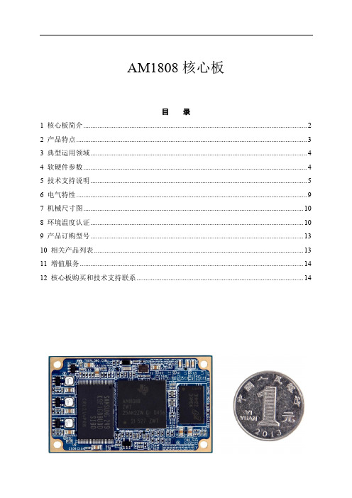
AM1808核心板目录1 核心板简介 (2)2 产品特点 (3)3 典型运用领域 (4)4 软硬件参数 (4)5 技术支持说明 (5)6 电气特性 (9)7 机械尺寸图 (10)8 环境温度认证 (10)9 产品订购型号 (13)10 相关产品列表 (13)11 增值服务 (14)12 核心板购买和技术支持联系 (14)1核心板简介基于TI AM1808 ARM9 CPU,标配工业级,主频456MHz;55mm*33mm,全国最小AM1808 ARM9核心板,采用精密工业级B2B连接器; TI推荐的超低功耗ARM处理器,适用于便携式设备;标配512MByte工业级NAND FLASH;标配128MByte工业级DDR2,可升级到256MByte;标配Linux操作系统、支持WinCE操作系统;通过环境测试认证,满足工业环境应用;图1 SOM-TL1808正面图2 SOM-TL1808背面由广州创龙自主研发的SOM-TL1808是全国最小的ARM1808 ARM9工业级核心板,55mm*33mm,仅硬币大小,功耗小、成本低、性价比高。
采用沉金无铅工艺的六层板设计,专业的PCB Layout保证信号完整性的同时,还经过严格的质量控制,通过环境测试认证,满足工业环境应用。
SOM-TL1808引出CPU全部资源信号引脚,二次开发极其容易,客户只需要专注上层运用,降低了开发难度和时间成本,让产品快速上市,及时抢占市场先机。
不仅提供丰富的Demo程序,还提供详细的开发教程,全面的技术支持,协助客户进行底板设计和调试以及软件开发。
2产品特点基于TI AM1808 ARM9工业级处理器,性价比极高,面向低成本工业系统;全国最小AM1808 ARM9核心板,55mm*33mm,仅硬币大小,减少占用空间;集成uPP、EMIF、SATA、USB 2.0等大数据传输接口,可与FPGA/CPLD配套使用;电源经过精心设计,功耗极低,发热量极小,手持设备首选;工业级核心板,遵循工业级设计,适合各种恶劣的工作环境;工业级精密B2B连接器,0.5mm间距,比排针和金手指更稳定,易插拔,防反插;3典型运用领域✓低成本数控系统✓海量数据存储设备✓智能家居✓智能网关✓智能电力系统✓便携式设备✓数据采集处理设备4软硬件参数硬件参数表1 硬件参数备注:广州创龙的OMAPL138、TMS320C6748、AM1808核心板在硬件上Pin to Pin兼容。
安拓 IN1808 系列 设置指南说明书

1I M P w w w .e x t r o n .c o m t a l l a t i o n i n s t r u c t i oo n n e c t i n g t h e e .IN1808 Series • Setup Guide4K @ 60 Hz at 4:4:4. They feature DisplayPort, HDMI, and DTP2 inputs, HDMI output and a mirrored Extron DTP2 outputextension to send video, audio, and control signals up to 330 feet (100 meters) over a shielded CATx cable. The IN1808 IPCP SA and IN1808 IPCP MA 70 models each have a built-in Extron IPCP Pro 355M IP Link Pro Control Processor, and an integrated 100 watt class D power amplifier. The IN1808 Series delivers high image quality, fast and reliable switching, Extron ProDSP audio processing, seamless video transition effects, logo keying, and HDMI loop out. The scalers can be controlled and configured over Ethernet, RS-232, or USB.This guide provides instructions for an experienced user to set up and configure the IN1808 (base model), IN1808 IPCP SA, and IN1808 IPCP MA 70 scalers. It covers how to perform basic operations using the front panel controls and selected Simple Instruction Set (SIS™) commands.NOTES:•For full installation, configuration, menus, connector wiring, and operation details, see the IN1806 and IN1808 Series User Guide at . For installation, configuration, and operation details of the embedded IPCP Pro 355M, see the IPCP Pro Series User Guide .•The IN1808 Series products can also be configured via the Extron Product Configuration Software (PCS), available at . For information on using PCS, see the IN1806 and IN1808 Series Help File.InstallationIN1808 Series Rear Panel ConnectorsFigure 1 shows the rear panel of the IN1808 IPCP SA rear panel. The IN1808 IPCP MA 70 rear panel is the same except that the embedded amplifier is mono while the SA model amplifier is stereo. The IN1808 base model rear panel does not have an embedded IPCP Pro 355M module (see figure 1, P ) or amplifier module (N ).Figure 1.Rear Panel Connectors, IN1808 IPCP SAA AC power connectorB DisplayPort input connector (input 1)C HDMI (with CEC) loop out connectorD DTP2/XTP input connectors (inputs 7 and 8)E HDMI (with CEC) output connector (1A)FDTP2/XTP/HDBaseT (with CEC) output connector (1B)G Over TP IR pass-through connectorH Analog line audio inputs 3 and 4I Analog mic/line audio inputs 1and 2 and adjacent phantom power LEDs J Analog line audio outputs 1 through 4K Remote RS-232 port L Reset LED M Reset buttonN Amplified audio output (IPCP modelsonly)o Aux mono or stereo analog lineaudio input connector P IPCP Pro 355M Control Processor (IPCP models only)Q HDMI inputs 2 through 6R LAN connector (IN1808 base modelonly, see the note and illustration below)IN1808 • Setup Guide (Continued)Mounting and CablingStep 1 — Mount the devicea. Turn off or disconnect all equipment power sources.b. Mount the IN1808 to a rack using the pre-installed side mounting brackets, or remove the brackets and use an optional19-inch rack under-desk mounting kit (see the mounting instructions provided with the kit, available at ).The IN1808 base model has a 1U high, full rack wide enclosure. The IN1808 IPCP models have 2U, full rack enclosures.Step 2 — Connect inputsMake the following input connections as needed:• Connect a DP source to the Input 1 DisplayPort connector (see figure 1, B, on the previous page).• Connect HDMI or DVI (with an appropriate adapter) sources to HDMI input connectors 2 through 6 (Q).• Connect DTP transmitters to the DTP2/XTP RJ-45 input connectors 7 and 8 (D). These connectors allow for remote powering of DTP transmitters. You can configure the TP inputs for XTP mode via SIS commands, the on-screendisplay (OSD), or PCS (see the IN1808 Series Help File). For cable wiring and recommendations, see Twisted PairRecommendations for DTP, XTP, and HDBaseT Communication on the next page.• Connect analog audio sources to:• The 5-pole captive screw line audio input connectors 3 and 4 (H) and the Aux connector (O) for balanced or unbalanced stereo audio. The Aux Line input is shared and can be associated with one or more video inputs.• Connect balanced or unbalanced mic or line level inputs to 3-pole Mic/Line captive screw connectors 1 and 2 (I).These inputs support optional +48 VDC phantom power, which is indicated by the LEDs at the left of the connectors.Step 3 — Connect outputsMake the following output connections as needed:• Connect an HDMI, or DVI with an appropriate adapter, display to HDMI/CEC output connector 1A (E).• Connect a DTP/XTP matrix switcher/HDBaseT compatible receiver to output connector 1B (F). For cable wiring and recommendations, see Twisted Pair Recommendations for DTP, XTP, and HDBaseT Communication.• To pass infrared data, connect a control device to the 3-pole IR Over DTP captive screw connector (see IR Over TP Wiring on the next page). Alternatively, insert RS-232 communication to a DTP/HDBaseT endpoint via Ethernet (see the IN1808Series User Guide for more information).• Connect balanced or unbalanced analog audio output devices to one or both 5-pole captive screw output connector pairs1 and2 or3 and4 (J). See Audio Wiring on the next page for more information.• For IPCP models, connect speakers to the amplifier module via the 5 mm 4-pole stereo (IN1808 IPCP SA) or 2-pole mono (IN1808 IPCP MA 70) Amplified Output connector (N).Step 4 — Connect control devices• To control the base model through Ethernet, connect a LAN or WAN to the LAN connector (R). To wire the RJ-45 connector to the cable, see Twisted Pair Recommendations for DTP, XTP, and HDBaseT Communication.For the IPCP models, connect a LAN or WAN to any of the AV LAN connectors on the IPCP Pro control processor (P). The default IP address of the scaler is 192.168.254.254. The default subnet mask is 255.255.255.0. The default gateway address is 0.0.0.0.• For serial RS-232 control, connect a host device to the 3-pole captive screw connector (K). The default baud rate is 9600.• For control through USB, connect a host device to the front panel USB mini-B port (see figure 2, H on page 4).Step 5 — Set up the IPCP Pro 355M control processor (IPCP models only)The Extron IPCP Pro 355M control processor (see figure 1, P) provides monitoring and control of a variety of external devices, such as projectors and lights. See the IPCP Pro Series Setup Guide, available at , for installation details.Step 6 — Connect powerConnect a 100 to 240 VAC, 50-60 Hz power source to the AC power connector (A).23Twisted Pair Recommendations for DTP , XTP , and HDBaseT CommunicationExtron recommends using the following practices to achieve full transmission distances and reduce transmission errors:•Use Extron XTP/DTP 24 SF/UTP cable for the best performance. At a minimum, Extron recommends 24 AWG, solid conductor, STP cable with a minimum bandwidth of 400 MHz.• Terminate cables with shielded connectors to the TIA/EIA-T568B standard (shown at right).•Limit the use of more than two pass-through points, which may include patch points, punch down connectors, couplers, and power injectors. If these pass-through pointsare required, use shielded couplers and punch down connectors.NOTE:When using shielded twisted pair cable in bundles or conduits, consider the following:• Do not exceed 40% fill capacity in conduits.• Do not comb the cable for the first 20 meters, where cables are straightened, aligned, and secured in tight bundles.• Loosely place cables and limit the use of tie wraps or hook-and-loop fasteners.•Separate twisted pair cables from AC power cables.Audio WiringWire the audio input and output connectors as shown at right. Use the supplied tie wrap to strap the audio cable to the extended tail of the connector. This does not apply to the amplified audio outputconnector on the SA and MA models.NOTE: The length of exposed wires is critical. The ideal length is 3/16 inch (5 mm).IR Over TP WiringTo transmit and receive IR signals, connect a control device to the three-pole Over TP IR connector (G, Tx, and Rx).NOTE: RS-232 data can be inserted via Ethernet only (see the IN1806 and IN1808 Series User Guide for details).TIA/EIA-T568B Pin Wire Color 1White-orange 2Orange 3White-green 4Blue 5White-blue 6Green 7White-brown 8BrownRJ-45ConnectorInsert Twisted Pair WiresPins:Balanced Audio OutputUnbalanced Audio OutputUnbalanced Audio InputBalanced Audio InputDo not tin the wires!Audio Inputs and Outputs 1 – 4 and AuxMic/Line Inputs 1 and 2Balanced Audio Input Unbalanced Audio Input4IN1808 • Setup Guide (Continued)Front Panel OverviewFigure 2 shows the front panel of the IN1808 IPCP SA and IPCP MA 70. The IN1808 base model is 1U high and has no IPCP Pro LEDs (H).Figure 2.Front Panel Features, IN1808 IPCP SA and IN1808 IPCP MA 70A Config portB Input selection buttons (1 through 8)C Logo buttonD Signal and Status LEDsE Menu and Enter buttonsF Navigation buttonsG Mic and Volume knobs and LEDsH IPCP Pro LEDs (IPCP models only)A Front panel configuration port — Connect a host device to the USB mini-B port for device configuration, control, and firmware upgradesB Input selection buttons (1 through 8) — Press one of these buttons to select an input. The buttons light amber for audioand video, green for video only, or red for audio only.C Logo button — Press this button to enable or disable the most recently selected logo slot. Press and hold the button toselect logo slot 1 through 8 using the input selection buttons (slots 9-16 are available via SIS commands only). See the IN1806 and IN1808 Series User Guide at for more information about logos.D Status LED indicators• Input signal LEDs — These eight LEDs light green for their corresponding inputs when active video content is detected on that input.• Output signal LEDs — Output LEDs 1A, 1B, and Loop light green when active video is being output, and blink amber when output video and sync are disabled.• Input HDCP LEDs — These eight LEDs light green for each input signal that is HDCP-encrypted. • Output HDCP LEDs — These three LEDs light green for an output when it is currently HDCP-encrypted.• DTP2 and DTP Input LEDs — These two LEDs light green if DTP or DTP2 power has been enabled on the corresponding input.•DTP2 and DTP Output LEDs — These Output LEDs light green if DTP or DTP2 power has been enabled on DTP output 1B.E Menu and Enter buttons — Press these buttons to access and navigate the on-screen display menu system.F Navigation buttons — Press these buttons to navigate through the on-screen display menu system or change settings.G Mic and Volume knobs and LED indicators — Rotate the Mic knob to adjust the microphone level. Rotate the Volumeknob to adjust the program or output volume level (configurable, see the IN1806 and IN1808 Series PCS Help File for more information). The eight LED indicators for each knob light according to the level being adjusted. The LEDs light in order from bottom to top to indicate steps from 1% (-99 dB) to 99% (-1 dB). The bottom LED blinks when the volume is muted. The top LED blinks when the volume is at 100% (12 dB).H IPCP Pro LED indicators — IPCP models only (see the IPCP Pro Series Setup Guide for details).Firmware UpdatesDownload firmware updates from the Extron website and upload them via the internal web pages or PCS.IN1808 Series Configuration Array To configure IN1808 Series, use the front panel controls, theon-screen display (OSD) menu, internal web pages, PCS, or SIScommands.On-screen Display (OSD) Menu SystemTo configure IN1808 Series using the OSD menu, connect a displayto either HDMI output 1A or to a DTP/XTP matrix switcher/HDBaseTcompatible device. The OSD menu consists of eight submenus accessedusing the front panel Menu or Enter button (see the example at right).Extron Product Configuration SoftwareTo configure IN1808 scalers using PCS, install the software (available onthe Extron website, ) to a PC connected to the scalervia Ethernet or front panel USB Config port. After the installation, start theprogram. For full instructions, press <F1> on the keyboard or click the ?button in the software and select Help File.Internal Web PagesTo configure the IN1808 Series using the factory-installed web pages in a web browser (see the example at right), connect the AV LAN connector (IPCP models) or LAN connector (base model) on the IN1808 to a LAN or WAN. The default IP address is 192.168.254.254.Basic SIS Command TableTo configure IN1808 Series with specific SIS commands via an RS-232, USB, or Ethernet connection, use the Extron DataViewer utility or a control system to send and receive SIS commands. The table below lists a selection of SIS commands. For a full list ofSIS commands and variables, see the IN1806 and IN1808 Series User Guide at .5668-3131-51 Rev. A02 19© 2019 Extron Electronics — All rights re served. All trademarks mentioned are the property of their respective owners. Worldwide Headquarters: Extron USA West, 1025 E. Ball Road, Anaheim, CA 92805, 800.633.9876For information on safety guidelines, regulatory compliances, EMI/EMF compatibility, accessibility, and related topics, see the Extron Safety and Regulatory Compliance Guide on the Extron website.。
AMTAX_sc教材

1HACH 产品技术培训-AMTAX sc 氨氮在线分析仪2 AMTAX™sc 氨氮在线分析仪3 AMTAX sc的应用领域•污水处理厂水质监测;•河流水质污染的监测;•自来水厂水质监测;4 AMTAX sc的部件组成•SC1000 控制器系统(显示模块和探头模块)•分析器•过滤器和架子:•样品过滤器(选择件):FILTRAXAMTAX sc包括:分析器\过滤器\控制器6紧定锁试剂使用说明分析部分密封门加热/通风装置电子部分AMTAX sc的特性和优点8 AMTAX sc的主要性能•测量范围很宽:0.05 to 1000 mg/l小于 5 分钟;•快速响应t90•自动清洗;•2点自动校正•测定仪一瓶试剂至少可用3个月,•全面自诊断功能9测量范围宽-AMTAX sc氨氮分析仪有三种量程可供选择。
只需更换相应的配套试剂以及在仪器菜单中选定所需量程即可实现不同量程之间的转换。
•低浓度量程: 0.05-20mg/L NH4-N •中浓度量程: 1-100mg/L NH4-N •高浓度量程: 10-1000mg/L NH4-N10响应时间快-实现对污水处理中营养物去除的过程监测在污水处理中营养物质的去除是一个非常关键和敏感的过程。
快速响应对于实现最佳运行起着至关重要的作用。
包括样品前处理和测量间隔选择在内,AMTAX sc氨氮分析仪的响应时间只有5分钟,是市场上响应最快的氨氮分析仪。
11气敏电极-GSE(使用电解液和盖式膜)•数据稳定,操作简单;•受外界干扰少;•容易更换和维护;12测量间隔可调,试剂消耗量小•用户根据要求可以设定测量周期5-120分钟;•试剂消耗量很少如果选择最短的测量周期,可以运行3个月。
13 Filterprobe–样品前处理系统(可选)哈希AMTAX sc氨氮分析仪可配合易于维护的能去除0.15微米以上颗粒物的过滤式探头一起使用。
滤液送到测定仪的同时,有气泡不断的清洗滤膜。
需要人工清洗时,只要用抹布或者海绵简单的擦拭即可。
美国专业左握式 стра托卡斯特 产品说明书
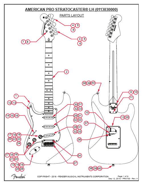
PARTS LAYOUT2105171213143736101516383940131718192024222317181913181925262124283233465368911273431293233313032333135383940PARTS LISTREF#DESCRIPTION PARTNUMBER 1BODY AM PRO STRAT LH 3TS0048702500 1BODY AM PRO STRAT LH OWT0056239505 1BODY AM PRO STRAT LH BLK0056239506 2NECK ASSY AM PRO STRAT LH RW7709884000 2NECK ASSY AM PRO STRAT LH MPL7709885000 3KEY 2-PIN MTG TALL LH 0073119000 4KEY 2-PIN MTG SHORT LH0073120000 5KEY WASHER 0053106049 6KEY BUSHING 0058820049 7STRING TREE W/HARDWARE0994911000 8SCREW SMAB 3 X 3/8 RHP STL NI0011357049 9NECK PLATE CORONA CA TILT W/HARDWARE0991445100 10SCREW SMA 8 X 1-3/4 OHP NI0015636049 11SET SCREW 1/4-20 X 3/8 OP NI HEX0031571000 12PICKGUARD STRAT AM STD LH P/B/P0056199000 12PICKGUARD STRAT AM STD LH MG/BLK/MG0055320000 13SCREW SMAB 4 X 1/2 OHP NI0015578049 145-WAY SELECTOR SWITCH0991367000 15SCREW MA 6-32 X 5/8 RH NI0994925000 16KNOB PICKUP SWITCH VINT AGED WHITE0994938000 17CONTROL 250K 10% R-AUDIO SPLIT SHAFT0063892000 18NUT HEX 3/8-32 X 3/320016352049 19WASHER LCK INTNL 3/8 X 500 X .02 NI0022384049 20CAPACITOR CD 1200pF 1000V 10%0065862000 21CAPACITOR MPF RDL .022MF 250 V 10%0024832049 22RES CF 1/4W 20K 5%0029006001 23RES CF 1/4W 150K 5%0024999001 24KNOBS STRAT 1-VOL 2-TONE AGED WHITE 0991369000 25FERRULE JACK CHROME 0991940000 26JACK PHONE OPEN CIRCUIT 110021956049 27BRIDGE ASSY AM PRO STRAT LH7709951000 27A BRIDGE PLATE TREM AM PRO STRAT LH CHROME7709900000*=NOT PICTURED IN DIAGRAMREF#DESCRIPTION PARTNUMBER 27B BLOCK TREMOLO AM DLX STRAT LH SILVER MET0077091000 27C BRIDGE SECTION ASSY NI AS STRAT SHORT0075123101 27D BRIDGE SECTION ASSY NI AS STRAT TALL0075123102 27E SPRING BRIDGE #1932 0019281049 27F SCREW M 4-40 X 5/8 RHP NI0015693049 27G SCREW M 8-32 X 3/8 FHP NI 0019656049 27H SPRING CLIP ULTRA0036531000 27I BUSHING NYL NAT .31 OD X .191 ID X .87 L7710005000 27J SET SCREW 10-32 X 3/16 HEX SKT FP BLX 0036615049 28PICKUP AM PRO SHAW BRIDGE LH AGED WHITE7709879000 29PICKUP AM PRO SHAW MIDDLE LH AGED WHITE7709891000 30PICKUP AM PRO SHAW NECK LH AGED WHITE7709893000 31PICKUP COVERS STRAT VINTAGE AGED WHITE0053824049 32TUBING LATEX CUT .300 X 1/8 ID X 1/4 OD0994916000 33SCREW TF 6-32 X 3/4 RHP STL NI0099346000 34BRIDGE PIVOT POST ASSY0093273000 35BACK COVER STRAT STD W/SLOT LH MG/BLK/MG0055322000 35BACK COVER STRAT STD W/SLOT LH P/B/P0056214000 36SPRING TREMOLO TENSION BLX 0018671049 37TREM CLAW SPRING TENSION ZINC0010272100 38STRAP BUTTONS CHROME W/HARDWARE0063267049 39FELT WASHERS WHITE0994930000 39FELT WASHER BLACK0994929000 40WOOD SCREW 6 X 1 OHP NI0016188049 *CASE AM ELITE GUITAR7710537000 *TRMOLO ARM AM PRO STRAT RH POLISHED SS7709929000 *TREMOLO ARM KNOB VINT AGED WHITE0994933000 *WRENCH HEX KEY 1/80023811049 *WRENCH HEX KEY .0500018531049 *WRENCH HEX KEY 1/160021109049 *WRENCH HEX KEY 3/320018622000*=NOT PICTURED IN DIAGRAMWIRING ASSEMBLY1200p F1200p FVOLUME CONTROL5-WAY SWITCHTONE 1CONTROLBLACK & WHITE WIRES FROM OUTPUTBLACK WIRE TO TREM CLAWGROUND LUG TO BODY CAVITYTONE 2 CONTROLCAPACITOR .022µFNECK PICKUPMIDDLE PICKUPBRIDGE PICKUPCAPACITOR 1200pFRESISTOR 20K ΩSHRINK TUBE CAPACITOR LEGSRESISTOR 150K ΩSWITCH AND CONTROL FUNCTION43215TONE CONTROLOF 5-WAY SWITCHINDICATES POSITION 5-WAYSWITCH POSITIONPICKUP IS OFFPICKUP IS ON 1BRIDGE PICKUP5 WAY SWITCH POSITIONNECK PICKUPMIDDLE PICKUPT1T1 & T2T2T2T2MASTER VOLUME 5-WAY SWITCHTONE 1 (T1)TONE 2 (T2)NECK PICKUP MIDDLE PICKUPBRIDGE PICKUPADDITIONAL SPECIFICATION DETAIL.054”.094”2-7/16”.820”.920”10-32THREAD.050” HEXØ.375”1/8” HEXSTAGGERED TUNING MACHINE SET W/HDWR P/N 0990820100OUTER SHAFT DIAMETER .394”TUNING MACHINE THRU-HOLEINNER DIAMETER .404”LOGO: AMERICAN PRO STRAT LHAPPLIED UNDER THE FINISHTRUSS ROD NUT P/N 0994943000TRUSS ROD ADJUSTMENT WRENCH:1/8” HEX KEY P/N 0023811049SADDLE HEIGHT ADJUSMENT WRENCH:.050” HEX KEY P/N 0018531049SHORT: P/N 0075536000TALL: P/N 00753840001ST FRET PROFILE12TH FRET PROFILENECK PROFILE: MODERN DEEP “C”FRET SIZE: JUMBO NARROW(FRET DIMENSIONS ARE BEFORE INSTALLATION)Ø.404”Ø.394”PLEASE NOTE: AS EACH NECK IS SANDED & FINISHED BY HAND, THICKNESS DIMENSIONS MAY VARY SLIGHTLY FROMTHOSE SHOWN.SADDLE HEIGHT ADJUSTMENT SCREWS:PICKUP SPECIFICATIONSNECKMIDDLE BRIDGEDC RESISTANCE 6.1 - 6.7KΩ6.4 -7.0KΩ6.4 - 7.0KΩMAGNETS ALNICO 2 & 3BEVELEDALNICO 5 & 2BEVELEDALNICO 5BEVELEDPOLARITY SOUTHNORTHSOUTHPOSITION。
ARTISAN技术集团设备说明书

Agilent 8163A/B Lightwave Multimeter Agilent 8164A/B Lightwave Measurement System Agilent 8166A/B Lightwave Multichannel System Configuration GuideJune 2002This guide provides configuration details for the Agilent816x family of mainframes and modules, includingoptions and accessories.Lightwave Multimeter Modules 816xx A 816xx B 8156xA see Figure 281672B - 1300nm, + 9dBm page 381482B - 1400nm, + 8.5dBm page 381682B - 1550nm, + 8dBm page 381642B - 1600nm, + 8.5dBm page 381682A - 1550nm, +8dBm page 381642A - 1600nm, +7dBm page 381480B - 1400nm page 381680B - 1550nm page 381640B - 1600nm page 381480A - 1400nm page 381680A - 1550nm page 381640A - 1600nm page 3Tunable Lasers: Low SSE Modules Tunable Lasers: High Power Modules Compact tunable Laser Modules81689A page 481689B 81649A8163A/B Lightwave MultimeterLight Source Modules FP Standard Modules page 681650A - 1310nm 81651A - 1550nm81652A - 1550/1625nm 81654A - 1310/1550nm FP High Power Modules page 681655A -1310nm 81656A - 1550nm81657A - 1310/1550nm DFB Laser Sources page 581662A 81663ACompact Tunable Laser Sources81689A page 481689B 81649APower Sensors Modules page 781630B 81634 B 81635 AFast Power Sensor Modules Page 781636B 81637B8166 Lightwave Multichannel SystemLightwave Multimeter Modules 816xx A 816xx B 8156xA see Figure 2Agilent high performance tunable laser module- 1 per 8164A/B Use 81645A filler module if no tunable laser is installedAny 816x and 8156x compact modules, also 8153A modulesAny 816x and 8156x compact modules, also 8153A modulesAny 816x and 8156x compact modules(8153 modules not allowed)8164A/B Lightwave Measurement SystemFigure 2Figure 3Figure 1Return Loss Modules page 1081610A - no laser 81611A - 1310nm 81612A - 1550nm81613A - 1310/1550nm 81614A - 1550/1625nmInterface Modules page 8-981618A – single interface 81619A – dual interface High Power Optical Heads 81622B page 881626B page 881628B page 8Standard Optical Heads 81623B page 881624B page 881627B page 92Attenuator Modules page 1181560A 81561A 81566A 81567A 81570A 81571A 81573A 81576A 81577AOptical Switch Modules page 1281591A 81591S 81592A 81952S 81594A 81594S 81595A 81595SInformation about Agilent connectors and connector interfaces can be found at /comms/oct-accessoriesTunable Lasers: All-band Module81600B 1440-1640nm page 3Specifiy81645A FillerModule if nohighperformancetunable laser isinstalled Note: 81xxxB-072 is highly recommendedover 81xxxB-071 to reduce front-panelconnector reflections which will greatlyreduce interference noise and spectralripple in the test setup.3816xxxB-OC-ACCS8163B-OC-STRGHTConnectorInterfaces forstraightconnectors8163B-OC-ANGLEDConnectorInterfaces forangledconnectorsOPTIONALCompact Tunable Laser Modules8163B-OC-ANGLEDConnector Interfaces for angled connectors8163B-OC-STRGHT Connector Interfaces for straight connectors Note: 816xxA/B-022 or 816xxA/B-072 are highly recommended over 816xxA/B-021 and 816xxA/B-071 to reduce front-panel reflections which will greatly reduce interference noise and spectral ripple in the test setup .4OPTIONAL816xxA/B-OC-ACCSDFB Source Modules8163B-OC-ANGLEDConnector Interfaces for angled contact 5For Laser Safety see page 13OPTIONAL8166xA-OC-ACCS8163B-OC-STRGHTConnector Interfaces for straight Source Modules 0 dBm Source 6FP Standard Source 8165xA-OC-ACCS OPTIONALPower Sensor ModulesPower Sensors Economy Modules81632A/B +10 dBm to –80 dBm (single channel)81635A +10 dBm to –110 dBm (dual channel)81636B + 10 dBm to –80 dBm (Fast Power Sensor)Connector Interfaces81000AI Diamond HMS-1081000FI FC/PC/SPC 81000GI D481000JI SMA81000KI SC/PC/APC 81000PI E-200081000SI DIN 47256 / 4108.681000VI ST 81002LI LCPower SensorsHigh Performance Modules 81633A/B +10 dBm to –90 dBm 81634A/B +10 dBm to –110 dBm81637B + 10 dBm to 80 dBm (Fast Power Sensor)81630B +28 dBm to –70 dBm 81000AI Diamond HMS-1081000FI FC/PC/SPC 81000KI SC81000SI DIN 47256/4108.681000VI ST 81000PI E-2000Following singleCombination is available 81000BB Bare Fiber Kit 81000FI FC81000FB Bare Fiber AdapterNote: All sensor inputs are non-contact and accept both straight and angled connectors.(bare fiber)8163xA/B-OC-PWRSENConnector Interfaces which fit 81000BB/FB8163xA/B-OC-PWRSEN Connector InterfacesSensor Module Interface for both angled and straight connectorsBare Fiber Adapter78163xA/B-OC-ACCS8163xA/B-OC-BAREOPTIONALOptical Heads (5mm Sensor)InterfaceModuleConnectorAdaptersThreadedConnectorInterfacesIntegralD-ShapedAdapters8162xB-OC-INTMOD8163B-OC-5MMOPTIONAL8163B-OC-D5MMOptical Heads (3mm Sensor)Connector Adapters (with intergral D-Shape)81001BA Bare Fiber 125µm 81001FA FC/PC/SPC/APC 81001KA SC/PC/APC 81001LA LC 81001MA MU81001PA E-2000,APC81001SA DIN 47256 / 4108.681001ZA BLANK AdapterNA ≤ 0.22 (Multi mode fiber)Configuration forconnectorized fibers and bare fiber981622B-OC-INTMODInterface ModuleConnector Adapters with integral OPTIONAL81627B-OC-ACCS8163B-OC-D3MM81624CE 4m extension cable81624RM Half-rack Mount Kit for 2Heads 81625RM Rack Mount Kit for 4HeadsReturn Loss ModulesReturn Loss Module8161xA-OC-ANGLEDConnector Interfaces for angled contacts8161xA-OC-ANGLEDConnector Interfaces for angled contacts81000SI DIN 4108.681610CC Reference Cable – for calibration of all 8161xA Return Loss Modules Connectors - DIN 4108.6 (connectors to modules) and FC/PC supplied (w/calibrated return loss values)An 81000SI connector interface is required to connect this cable to the module.Reference Cable108161xA-OC-ANGLEDOPTIONALOptical Attenuator ModulesOptical Attenuator Angled Contact InterfaceOptical Attenuators for Angled Contact Interface 81561A (single slot)Optical Attenuator 81571A (single slot)Optical Attenuator for high power 81567A (dual slot)Optical Attenuator with Power Control 81577A (dual slot)Optical Attenuator with Power Control for high power Connector Interfaces 81000 HI E-2000 APC 81000 KI SC/APC 81000 NI FC/APC 81000 SI DIN 4108.6Optical Attenuators for Straight Contact Interface 81560A (single slot)Optical Attenuator 81570A (single slot)Optical Attenuator for high power 81566A (dual slot)Optical Attenuator with Power Control 81576A (dual slot)Optical Attenuator with Power Control for high powerConnector Interfaces 81000 AI HMS-1081000 FI FC/PC/SPC 81000 GI D481000 HI E-200081000 KI SC/PC/SPC 81000 SI DIN 4725681000 VI STOptical Attenuator Straight Contact Interface8163B-OC-STRGHTConnector Interface for straight connectors 8163B-OC-ANGLEDConnector Interface for angled connectors11815xxA-OC-ACCSOPTIONALOptical Attenuator with SMF pigtail 2m lengthFC/PCOptical Attenuator with SMF pigtail 81573A (single slot)Optical Attenuator for high powerOptical Switch ModulesOptical Switch for Angled Contact ConnectorsOptical Switch for Straight Contact Connectors8159xA/S-OC-CONIFCOptical Switches for Straight Contact Connectors81591S Optical switch 1x281592S Optical switches2 independent 1x2 in one module 81594S Optical switch, 2x2 non-blocking (crossover)81595S Optical switch, 1x4Optical Switches for Angled Contact Connectors81591A Optical switch 1x281592A Optical switches2 independent 1x2 in one module 81594A Optical switch, 2x2 non-blocking (crossover)81595A Optical switch, 1x48159xS-FCIFixed FC /PC / SPC connector interfaces 8159xS-SCIFixed SC /PC / SPC connector interfaces 8159xA-FCIFixed FC /APC connector interfaces 8159xA-SCIFixed SC /APC connector interfacesMANDATORY AND MUTUALLY EXCLUSIVE12Laser Safety Information81611A 1310nm RL81612A 1550nm RL81613A 1310/1550nm FP81614A 1550/1625nm RL81650A 1310 nm FP81651A 1550 nm FP81652A 1550/1625 nm FP81654A 1310/1550 nmThe laser sources listed directly above are classified as Class 1 according to IEC 60825-1 (2001).All laser sources comply with 21 CFR 1040.10 except for deviations pursuant to Laser Notice No. 50, dated 2001-July-26.CLASS 1 LASER PRODUCT(IEC 60825-1 / 2001)81655A 1310nm FP81656A 1550 nm FP81657A 1310/1550 nm FP81662A C- and L-Band DFB81663A C-band DFB81600B All-band TLS81480B 1400nm TLS81680B 1550nm TLS81640B 1600nm TLS81672B 1300nm TLS81482B 1400nm TLS81682B 1550nm TLS81642B 1600nm TLS81480A 1400nm TLS81640A 1600nm TLS81642A 1600nm TLS81680A 1550nm TLS81682A 1550nm TLS81689A 1550nm TLS81689B 1550nm TLS81649A 1595nm TLSAll laser sources specified by this data sheet are classified as Class 1M according to IEC 60825-1 (2001).All laser sources comply with 21 CFR 1040.10 except for deviationspursuant to Laser Notice No. 50, dated 2001-July-26Further Information about Agilent connectors and connector interfaces can be found at /comms/oct-accessories13Agilent Technologies’Test and MeasurementSupport, Services, and AssistanceAgilent Technologies aims to maximize the value you receive, while minimizing your risk and problems. We strive to ensure that you get the test and measurement capabilities you paid for and obtain the support you need. Our extensive support resources and services can help you choose the right Agilent products for your applications and apply them successfully. Every instrument and system we sell has a global warranty. Support is available for at least five years beyond the production life of the product. Two concepts underlie Agilent's overall support policy: "Our Promise" and "Your Advantage."Our PromiseOur Promise means your Agilent test and measurement equipment will meet its advertised performance and functionality. When you are choosing new equipment, we will help you with product information, including realistic performance specifications and practical recommendations from experienced test engineers. When you use Agilent equipment, we can verify that it works properly, help with product operation, and provide basic measurement assistance for the use of specified capabilities, at no extra cost upon request. Many self-help tools are available.Your AdvantageYour Advantage means that Agilent offers a wide range of additional expert test and measurement services, which you can purchase according to your unique technical and business needs. Solve problems efficiently and gain a competitive edge by contracting with us for calibration, extra-cost upgrades, out-of-warranty repairs, and on-site education and training, as well as design, system integration, project management, and other professional engineering services. Experienced Agilent engineers and technicians worldwide can help you maximize your productivity, optimize the return on investment of your Agilent instruments and systems, and obtain dependable measurement accuracy for the life of those products.By internet, phone, or fax, get assistance with all your test & measurement needsOnline assistance:/comms/lightwavePhone or FaxUnited States:(tel)180****4844Canada:(tel)187****4414(fax) (905) 206 4120Europe:(tel) (31 20) 547 2323(fax) (31 20) 547 2390Japan:(tel) (81) 426 56 7832(fax) (81) 426 56 7840Latin America:(tel) (305) 269 7500(fax) (305) 269 7599Australia:(fax) (61 3) 9210 5947New Zealand:(tel) 0 800 738 378(fax) 64 4 495 8950Asia Pacific:(tel) (852) 3197 7777(fax) (852) 2506 9284Product specifications and descriptions in this document subject to change without notice. Copyright © 2002 Agilent TechnologiesJune, 27 20025988-1571EN Related Literature:Agilent 8163B Lightwave MultimeterAgilent 8164B Lightwave Measurement SystemAgilent 8166B Lightwave Multichannel SystemTechnical Specificationsp/n 5988-3924ENAgilent 8163A Lightwave MultimeterAgilent 8164A Lightwave Measurement SystemAgilent 8166B Lightwave Multichannel SystemTechnical Specificationsp/n 5988-1568ENAgilent 81480/680/640BAgilent 81672/482/682/642BTunable Laser SourcesTechnical Specificationsp/n 5988-5508ENAgilent 81480/680/640A Tunable LasersAgilent 81682/642A Tunable LasersTechnical Specificationsp/n 5988-4027ENAgilent 81689A/81689B/81649ACompact Tunable Laser ModulesTechnical Specificationsp/n 5988-3675ENAgilent 81662A DFB LaserAgilent 81663A DFB LaserAgilent Fabry-Perot LaserTechnical Specificationsp/n 5988-1570ENAgilent Power Sensor ModulesAgilent Optical HeadsAgilent Return Loss ModulesTechnical Specificationsp/n 5988-1569ENAgilent 81560A/81561A Optical AttenuatorsAgilent 81566A/81567A Optical Attenuators with Power Control Technical Specificationsp/n 5988-2696EN。
夏普1808S说明书
夏普1808S说明书夏普1808S说明书夏普1808s基本参数 :产品类型数码复合机颜色类型黑白涵盖功能复印/打印/扫描速度类型低速最大原稿尺寸 A3进纸盘容量标配纸盒:250页手送纸盘:100页最大容量:1100页内存容量 64MB耗材描述感光鼓:AR-205DR-C墨粉盒:MX235CT,MX-236CT双面器不支持自动输稿器选配,单面自动输稿器,容量40页网络功能不支持接口类型 USB2.0复印功能:复印速度 18cpm复印分辩率扫描:400x600dpi,输出:600x600dpi 复印尺寸 A3预热时间 25秒首页复印时间 7.2秒连续复印页数 1-999页缩放范围 25-400%(以1%为单位),(使用SPF时,50-200%)复印倍率 50%,70%,81%,86,100%,115%,122%,141%,200%灰度等级 256级打印功能:打印控制器标准配置打印速度 18ppm打印分辨率 600x600dpi打印语言 SPLC扫描功能:扫描控制器标准配置扫描幅面 A3扫描分辨率黑白:300x300dpi,彩色:400x200dpi输出格式 BMP,TIFF,PDF扫描其它性能彩色扫描描工具:Button Manager其它特性:主机尺寸 591x550x495mm(包括原稿盖板)主机安装空间约28.6kg(不含载体和墨粉盒)电源 220V(?10V),50Hz功率最大1.2KW系统平台 Windows 2000/XP(32/64bit)/Vista(32/64bit)/7(32/64bit) 复印机附件:包装清单主机 x1 墨粉盒 x1电源线 x1操作手册 x1CD-ROM光盘 x1保修卡 x1。
HKCSA资料
© Faraday Technology. As part of continual product improvement the specifications, details and dimensions shown in this publication are subject to change without noticeThese filters are specifically designed for antialiasing and reconstruction in low cost analogue to digital and digital to analogue conversions operating at HDTV sampling rates, they are typically used in HDTV monitors, television sets and monitor quality interface products.Small Dipped SIL package Luminance and Colour Difference versions Flat and Sinx/x corrected versionsLow cost1Measured against sinx/x roll off for a Sampling Frequency of 74.250 MHz.2Measured against sinx/x roll off for a Sampling Frequency of 37.125 MHz.Order Code HKYFA HKYSA HKCFA HKCSA Filter Shape Lowpass Lowpass Lowpass Lowpass Passband Shape Flat Sinx/x Flat Sinx/x Sampling Frequency 74.250 MHz 74.250 MHz 37.125 MHz 37.125 MHz Insertion Loss at 100 kHz < 1.0 dB < 3.5 dB < 1.0 dB < 3.5 dB End Of Passband30.0 MHz 30.0 MHz 15.0 MHz 15.0 MHz Passband Amplitude Ripple < 1.0 dB < 1.0 dB 1< 1.0 dB < 1.0 dB 2Start Of Stopband 45.0 MHz 45.0 MHz 22.0 MHz 22.0 MHz Stopband Attenuation >30 dB >30 dB >28 dB >28 dB Delay Time at 200 kHz 13 ns 10 ns 20 ns 17 ns Impedance 75 ohms 75 ohms 75 ohms 75 ohms Temperature Range 0 to 700 C 0 to 700 C 0 to 700 C 0 to 700 C Aqueous Washable Yes Yes Yes Yes PackageDR00034ADR00064ADR00034ADR00064AHK SERIESLOW COST HDTV FILTERSPACKAGE DETAILFaraday Technology Ltd.Tel:+ 44 (0)1782 661501 Croft Road Industrial Estate,Fax:+ 44 (0)1782 630101 Newcastle, Staffordshire Email:sales@ ST5 0QZ. England.Web site:。
