IA系统FCP270说明书
浅谈福清核电DCS的IA和TRICON平台接口的实现和问题

安 排 在 生 产 厂 中进 行 ,让 学生 看 到 实物 有 利 与 学 生 的理 解 在 教 育 的 改 革 发 展 讲 解机 床 电 气控 制 线路 时 由 于 学 生 对 于机 床 本 身结 构 、功 用 、
福 清 核 电 1~4号 机 组 采 用 M310改 进 型 工 程 技 术 方 案 . 工 程 技 术 方 案 的 主 要 设 计 目标是 采 用 数 字化 仪 控 技 术 和 先 进 主 控 室设 计 福 清 核 电数 字化 仪 控 主 要 采 用 DCS 系统 实现 . 由 lnvensys集 团 牵 头 的 IOM/ATOS联 队 负 责供 货 。其 中二 层 包括 主 控 室在 内由 ATOS分 包 ,负责 二 层 相 关 设 计 、设 备 制 造 及 相 关 验 证 工 作 .采 用 ATOS的 ADACS—N 平 台 实施 电 站 信 息 和控 制 系统 (KlC) 一层 部 分 采 用 了 Invensys集 团的 I/A 控 制 系统 和 TRICON 系统 ,其 中 NC、NC+级 过 程 控 制 部 分 采 用 I/A 平 台 ,反 应 堆 保 护 系统及 堆 芯控 制 系统 采 用 TRICON 平 台
素 养得 到 了提 升 .. 教 学 课 堂 与 工 厂 实 习的 结 合 是 进 行 教 学 的 有 效 形 式 .教
师在 车 间 中教 学 ,由 于 高 职 学 生 基 本 没 有 工 厂 的 工 作 经验 .对
综 上 所 述 ,《电机 与 电气 控 制 技 术 》 课 程 的 改 革 是 十 分 重 要 的 ,在 课 程 教 学 和 职 业 资格 考 试 相 结 合 ,增 加 学 生 学 习 的 积 极 性 ,对 学 生 未 来 的 发 展 有 很 好 的 帮 助 .推 行 改 革 需 要 教 师观
高压溶出典型控制在IA系统中的运用
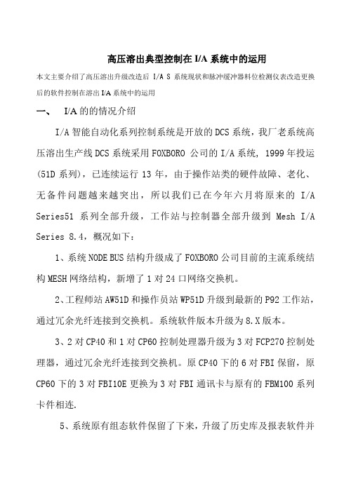
高压溶出典型控制在I/A系统中的运用本文主要介绍了高压溶出升级改造后I/A S系统现状和脉冲缓冲器料位检测仪表改造更换后的软件控制在溶出I/A系统中的运用一、I/A的的情况介绍I/A智能自动化系列控制系统是开放的DCS系统,我厂老系统高压溶出生产线DCS系统采用FOXBORO 公司的I/A系统, 1999年投运(51D系列),已连续运行13年,由于操作站类的硬件故障、老化、无备件问题越来越突出,所以我们已在今年六月将原来的I/A Series51系列全部升级,工作站与控制器全部升级到Mesh I/A Series 8.4,概况如下:1、系统NODE BUS结构升级成了FOXBORO公司目前的主流系统结构MESH网络结构,新增了1对24口网络交换机。
2、工程师站AW51D和操作员站WP51D升级到最新的P92工作站,通过冗余光纤连接到交换机。
系统软件版本升级为8.X版本。
3、2对CP40和1对CP60控制处理器升级为3对FCP270控制处理器,通过冗余光纤连接到交换机。
原CP40下的6对FBI保留,原CP60下的3对FBI10E更换为3对FBI通讯卡与原有的FBM100系列卡件相连.5、系统原有组态软件保留了下来,升级了历史库及报表软件并进行了组态。
配置图如下:工程师站AW70 X2操作员站WP70 X 2DCS系统升级后的软硬件配置,系统性能及可靠性得到了很大提高,系统故障诊断功能也大大增强。
操作站功能强大,维护更方便了且大大降低了成本。
高压溶出是一较为复杂的过程控制对象,它的控制参数较多,调节量之间互相影响严重,都是通过I/A s控制的,包括许多复杂的控制。
具体讲主要是物位控制、流量控制、温度控制,以保证机组安全运行。
因篇幅有限,下面仅以脉冲缓冲器的液位控制在I/A S中的应用来介绍。
溶出生产线中每条线有两台脉冲缓冲器,以Ⅰ系列为例,它们分别是TP101、TP102。
每台缓冲器的作用完全相同,因而控制机理也完全相同,本文只以TP101为对象进行论述。
某核电厂DCS(IA)系统概述
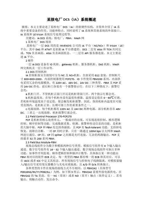
某核电厂DCS(IA)系统概述摘要:本文主要论述了某核电厂DCS(IA)的软硬件结构,并简单介绍了IA系统中重要设备的作用、功能和特点。
同时说明了IA系统和其他系统的外部接口、IA系统和1E tricon系统信号处理过程等。
关键词:IA DCS系统;核电厂;FBM;Mesh网1 某核电厂DCS现状某核电厂一层DCS用的是INVENSYS公司的IA平台(NC/NC+)和tricon(1E)平台,其中DAS和ATWT是依据IA平台搭建的。
DCS二层有Atos和TCN共同完成,TCN负责画面,Atos负责画面组态。
一二层有API服务器连接。
本文主要论述IA平台。
2 硬件一层IA DCS 设备有IO机柜、gateway机柜、服务器机柜、DAS机柜、Mesh网交换机及一层工作站等。
2.1 DCS控制机柜IA控制柜按安全级别可分为NC及NC+机柜,全部采用G12套装,控制柜尺寸800×800×2000。
内部控制器使用FCP270,IO卡件使用FBM200系列,内部供电采用冗余的电源模块,有220V AC、48V DC、24V DC三种类型,FBM及FCP采用24V DC供电。
前后柜门各装有一个报警指示灯,在以下三种情况下,报警灯会亮:a.机柜门开。
不管机柜正面门开还是机柜背面门开,两个指示灯都会亮。
b.机柜温度高。
在每个机柜内设有温度传感器,温度设定值在0~60℃可调,若机柜环境温度高于设定值,便会触发机柜报警。
因此,保持机柜内温度在可接受范围内,是机柜正常、长期可靠工作的重要条件之一。
c.电源故障。
每个机柜都有220V AC及24V DC两种电源,部分机柜存在48V DC。
三者之一出现故障,机柜报警灯就会亮。
2.2 Field Control Processor 270-FCP270FCP是机柜的核心处理单元,一般成对的出现,可实现连续控制、梯形逻辑控制、顺序控制等功能,完成数据采集、检测、报警和传送信息的功能,是机柜的大脑中枢。
博创科技 UP-TECH S2410 P270 DVP 经典开发平台 硬件说明书
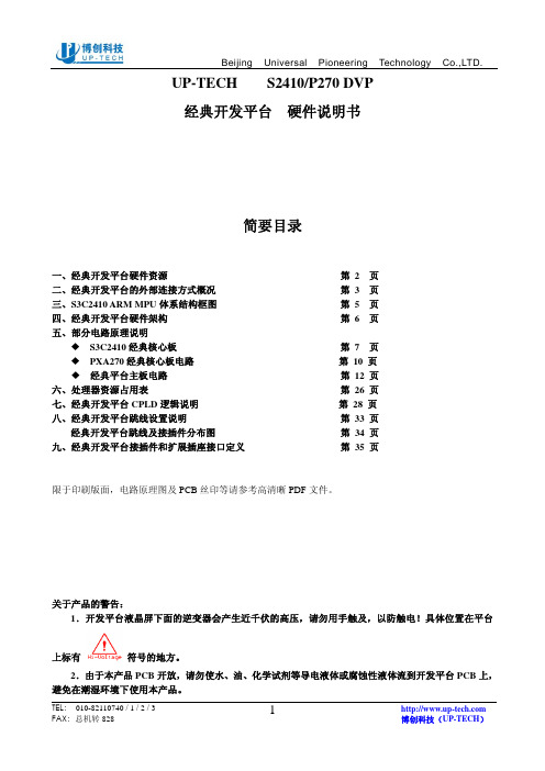
UP-TECH S2410/P270 DVP经典开发平台硬件说明书简要目录一、经典开发平台硬件资源第 2 页二、经典开发平台的外部连接方式概况第 3 页三、S3C2410 ARM MPU体系结构框图第 5 页四、经典开发平台硬件架构第 6 页五、部分电路原理说明S3C2410经典核心板第 7 页PXA270经典核心板电路第 10 页经典平台主板电路第 12 页六、处理器资源占用表第 26 页七、经典开发平台CPLD逻辑说明第 28 页八、经典开发平台跳线设置说明第 33 页经典开发平台跳线及接插件分布图第 34 页九、经典开发平台接插件和扩展插座接口定义第 35 页限于印刷版面,电路原理图及PCB丝印等请参考高清晰PDF文件。
关于产品的警告:1.开发平台液晶屏下面的逆变器会产生近千伏的高压,请勿用手触及,以防触电!具体位置在平台上标有符号的地方。
2.由于本产品PCB开放,请勿使水、油、化学试剂等导电液体或腐蚀性液体流到开发平台PCB上,避免在潮湿环境下使用本产品。
一、经典开发平台硬件资源1.核心板:A )S3C2410核心板:S3C2410 ARM CPU、64M SDRAM、64M NAND FLASH,通过280Pin精密插座与主板连接。
核心板上可以配置2M或4M容量的Nor Flash AM29LV160/320,硬件支持从NorFlash启动并可增加NandFlash容量。
B)PXA270核心板:PXA270 XScale CPU、64M SDRAM、64M NAND FLASH,16M Nor FLASH。
经典平台的核心板接口设计完全兼容博创的PXA270核心板和S3C2410核心板,在软件支持下,两个核心板在经典开发平台主板上均可以实现大部分硬件功能,完全可以替换原有的2410-S和270A系列产品。
2.双100M EtherNet网卡:由两片DM9000AE构成的双网卡,一般可只用其一。
MDA 270 电源技术特性说明书
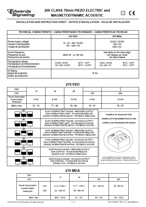
270 MDATECHNICAL CHARACTERISTIC – CARACTERISTIQUES TECHNIQUES – CARACTERÍSTICAS TÉCNICAS270 PZO 270 MDA Power supply voltage Tension d’alimentation Voltaje de alimetación 12 - 24 - 48V AC/DC 120 - 240V AC12/24V AC/DC 120V AC 240V AC Sound frequency Fréquence du son Frecuencia del sonido2800 Hz (± 100 Hz)See table on the back page Voir tableau au verso Ver tabla traseraTemperature ratingsTempérature de fonctionnement Temperatura funcionamiento 12÷48V AC/DC 60°C / 140°F 120, 240V AC/DC 56°C / 132.8°FIP RatingDegré de protection Grado de protecciónIP 5412/24V AC/DC 60°C / 140°F 120, 240V AC 50°C / 122°FINSTALLATION AND INSTRUCTION SHEET - NOTICE D’INSTALLATION - HOJA DE INSTALACIÓN1 2 3on1 2 3on1 2 3on1 2 3on1 2 3on1 2 3onSLOW INTERMITTENT SOUND - REDUCED OUTPUT SON INTERMITTENT LENT - PUISSANCE REDUITE SONIDO INTERMITENTE LENTO - POTENCIA REDUCIDASLOW INTERMITTENT SOUND - MAXIMUM OUTPUT SON INTERMITTENT LENT - PUISSANCE MAXIMALE SONIDO INTERMITENTE LENTO - POTENCIA MÁXIMAFAST INTERMITTENT SOUND - REDUCED OUTPUT SON INTERMITTENT RAPIDE - PUISSANCE REDUITE SONIDO INTERMITENTE RAPIDO - POTENCIA REDUCIDAFAST INTERMITTENT SOUND - MAXIMUM OUTPUT SON INTERMITTENT RAPIDE - PUISSANCE MAXIMALE SONIDO INTERMITENTE RAPIDO - POTENCIA MÁXIMACONTINUOUS SOUND - REDUCED OUTPUT SON CONTINU - PUISSANCE REDUITE SONIDO FIJO - POTENCIA REDUCIDACONTINUOUS SOUND - MAXIMUM OUTPUT SON CONTINU - PUISSANCE MAXIMALE SONIDO FIJO - POTENCIA MÁXIMAVDC 122448VAC 120 240 Power Consumption Consommation Absorpción 3 mA 6 mA 13 mA 4 mA 10 mA dB(A) max72 - 7977 - 8579 - 8975 - 8178 - 87FAST INTERMITTENT SOUND - REDUCED OUTPUT SON INTERMITTENT RAPIDE - PUISSANCE REDUITE SONIDO INTERMITENTE RAPIDO - POTENCIA REDUCIDAEXAMPLE OF SOUND SETTINGEXEMPLE DE PROGRAMMATION DU SONEJEMPLO DE PROGRAMACIÓN SONIDO270 PZOVDC 12 24VAC 120 240 Power Consumption Consommation AbsorpciónVAC VDC 0.12 - 0.95 A30 - 335 mA 0.17 - 1.06 A45 - 450 mA40 - 105 mA25 - 60 mAdB(A) max86.5 - 103.591 - 10793 - 103 93 - 103.5© 2010 UTC Fire & Security. All rights reservedP/N 3101893 • REV 1.0 • ISS 09DEC101 / 2NOTICE:ATTENTION:ATENCIÓN:A Bon1 2 3 4 5 on1 2 3 4 5 on1 2 3 4 5 on1 2 3 4 5onREGULATORY INFORMATION - REINSEGNEMENTS RÉGLEMENTAIRES - INFORMACI ÓN ADMINISTRATIVA :Edwards Signaling: Edwards, A division of UTC Fire & Security Americas Corporation, Inc. 8985 Town Center Parkway, Bradenton, FL 34202, USACONTACT INFORMACION - COORDONNÉES - INFORMACIÓN DE CONTACTO : w Installation must be carried out by qualified personnel - L’installation doit être effectuée par du personnel qualifié - Personal calificado debe realizar la instalación© 2010 UTC Fire & Security. All rights reservedP/N 3101893 • REV 1.0 • ISS 09DEC10 2 / 2 C US IND. CONT. EQ.TYPE 1 ENCLOSUREE342009。
WGB-270A系列技术及使用说明书v1.00
WGB-270A系列微机备自投装置技术及使用说明书(Version 1.00)许继电气股份有限公司XJ ELECTRIC CO.,LTD.WGB-270A系列微机备自投装置WGB-270A是许继最新推出的HELLO系列产品之一,它是许继秉承数十年来在电力系统二次设备制造领域的成功经验,为用户提供的具有高品质、高性价比的保护测控一体化装置。
WGB-270A系列微机备自投装置主要适用于220kV及以下电压等级的备用电源自投。
H、E、L、L、O品质是许继HELLO系列产品的共同特点,具体如下:⏹H:即High,高品质包括:◆高科技:采用现场组态技术(FCT)、可视化的软件开发技术(VLD)。
◆高质量:以专业的、成熟的软硬件平台为依托,丰富的运行经验和充分验证的原理算法为基础,自动测试为前提,先进的研发管理理念和研发开发管理工具为手段,保证研发、生产、制造过程中各个环节的质量,为用户提供高品质的产品。
⏹E:即Easy,工作轻松包括:◆易使用:人机界面友好、仿WINDOWS操作菜单,具有调试向导系统和一键完成定检功能,使现场调试、维护、定检工作变得轻松。
⏹L:即Low,低消耗包括:◆低投入成本:不同的装置共享插件,降低了购买装置和备件储备成本。
◆低故障率:先进的检测技术和完善的生产质量保障体系,使得产品的故障大大降低,大幅度减少了被保护对象的停运时间。
⏹L:即reaLize,实现技术包括:◆平台化:软件、硬件的设计都采用平台化的思想,使不同电压等级的保护装置可以共享硬件平台,不同的硬件平台可以共享软件,降低了日后硬件、软件的升级和维护工作。
◆专业化:不同领域的研发工作都由专业人员完成,通过规范的接口集成不同层次、不同领域的研发成果,让用户充分享受到高科技的产品。
◆模块化:对所有的功能模块分别封装成柔性继电器,不同装置通过配置不同的柔性继电器完成该装置的功能,能够顺速响应不同用户的个性化需求。
⏹O:即technOlogy,专利技术包括:◆VLD开发技术:VLD开发工具类似与“PLC”的开发环境,在该环境下所有的保护逻辑都是由不同可视化的柔性继电器组成,实现了业界用继电保护语言开发程序的梦想。
600MW超超临界机组DCS IA系统供货范围

600MW超超临界机组DCS I/A系统供货范围说明1概述上海Foxboro有限公司有着多年在控制领域领先的技术和控制经验,针对于600MW超超临界机组我们配置了一套符分散控制系统——IA,以实现电厂建设中关于机组中各项在技术规范书中要求的控制功能和满足今后在电厂中控制系统保持可靠,经济,先进等方面的控制方案。
基于上海Foxboro有限公司多年来对过程控制系统的研究和积累的火电厂控制方案的经验,以成功的方案和成熟的技术根据本项目技术规范书的要求提供一套完整并且应用于本项目的控制方案。
以下的方案是我们在对600MW超超临界机组成功地完成控制系统的设计、组态、培训、服务的基础上提出的。
我们为很多工程提供了实现 DAS、MCS、 SCS、 ECS、BMS(FSSS)和DEH ,MEH的IA分散控制系统积累了各种电厂锅炉的控制经验并且熟悉发电厂的运行要求,为更高级的控制和运行需要提供了技术依据。
通过我们与所有相关单位的密切合作,一定能够使这个配置方案充分发挥出 DCS 的能力,使用户获得最佳的效益。
1.1 工程概述工程安装2×600MW超超临界燃煤机组。
锅炉、汽轮机、发电机为哈尔滨锅炉厂有限责任公司、哈尔滨汽轮机有限责任公司、哈尔滨汽轮发电机有限责任公司的产品。
1.2 主设备及辅助设备概况1.2.1锅炉:超超临界、变压运行直流炉、带启动循环泵、单炉膛、一次中间再热、平衡通风、墙式切圆燃烧、紧身封闭结构、固态排渣、全钢构架、全悬吊结构Π型。
锅炉型号:HG-1795/26.15-YM1型锅炉主要热力参数如下表:1. 压力单位中“g”表示表压。
“a”表示绝对压(以后均同)。
2.锅炉B-MCR工况对应于汽机VWO工况。
1.2.2 汽轮机:超超临界、一次中间再热、单轴、两缸两排汽、单背压、凝汽式汽轮机。
汽轮机具有八级非调整回热抽汽,给水泵汽轮机排汽进入主机凝汽器。
汽轮机额定转速为3000转/分。
汽轮机型号:CLN600-25/600/600型汽轮机主要参数汇总表1.2.3发电机:额定功率为600 MW,水氢氢冷发电机型号:QFSN4-600-2型1.2.4 辅助设备a)制粉系统采用中速磨煤机、正压直吹式制粉系统,每台锅炉配6台中速磨煤机,其中1台备用;b)每台锅炉配6台电子称重皮带给煤机,5台运行1台备用;c)每台锅炉配2台定速、电动、轴流式、动叶可调一次风机;d)每台锅炉配2台定速、电动、轴流式、动叶可调送风机;e)每台锅炉配2台定速、电动、轴流式、静叶可调吸风机;f)每台锅炉配2套一次风暖风器、2套二次风暖风器及其附件;g)每台锅炉配2台效率为99.86%的双室五电场静电除尘器;h)每台机组配置二台50%B-MCR容量的汽动给水泵,一台电动定速给水泵作为启动用泵,每台汽动给水泵有一台定速电动机拖动的前置泵;i)回热系统配置3台高压加热器、4台低压加热器、1台除氧器。
IA240 硬件用户手册说明书

IA240 Hardware User’s ManualEdition 8.1, May 2018/product© 2018 Moxa Inc. All rights reserved.IA240 Hardware User’s ManualThe software described in this manual is furnished under a license agreement and may be used only in accordance withthe terms of that agreement.Copyright Notice© 2018 Moxa Inc. All rights reserved.TrademarksThe MOXA logo is a registered trademark of Moxa Inc.All other trademarks or registered marks in this manual belong to their respective manufacturers.DisclaimerInformation in this document is subject to change without notice and does not represent a commitment on the part of Moxa.Moxa provides this document as is, without warranty of any kind, either expressed or implied, including, but not limited to, its particular purpose. Moxa reserves the right to make improvements and/or changes to this manual, or to the products and/or the programs described in this manual, at any time.Information provided in this manual is intended to be accurate and reliable. However, Moxa assumes no responsibility for its use, or for any infringements on the rights of third parties that may result from its use.This product might include unintentional technical or typographical errors. Changes are periodically made to the information herein to correct such errors, and these changes are incorporated into new editions of the publication.Technical Support Contact Information/supportMoxa AmericasToll-free: 1-888-669-2872 Tel: +1-714-528-6777 Fax: +1-714-528-6778Moxa China (Shanghai office) Toll-free: 800-820-5036Tel: +86-21-5258-9955 Fax: +86-21-5258-5505Moxa EuropeTel: +49-89-3 70 03 99-0 Fax: +49-89-3 70 03 99-99Moxa Asia-PacificTel: +886-2-8919-1230 Fax: +886-2-8919-1231Moxa IndiaTel: +91-80-4172-9088 Fax: +91-80-4132-1045Table of Contents1.Introduction ...................................................................................................................................... 1-1Overview ........................................................................................................................................... 1-2 Package Checklist ........................................................................................................................ 1-2Product Features ......................................................................................................................... 1-2Product Hardware Specifications .................................................................................................... 1-3 Hardware Introduction ........................................................................................................................ 1-4 Appearance ................................................................................................................................ 1-4Dimensions................................................................................................................................. 1-5LED Indicators ............................................................................................................................ 1-5Reset-Type Buttons ..................................................................................................................... 1-5Real Time Clock .......................................................................................................................... 1-6 Placement Options .............................................................................................................................. 1-6 DIN-Rail Mounting ....................................................................................................................... 1-6Wall Mounting (Optional) .............................................................................................................. 1-7 Hardware Connection Description ......................................................................................................... 1-8 Wiring Requirements ................................................................................................................... 1-8Connecting the Power .................................................................................................................. 1-8Grounding the IA240 ................................................................................................................... 1-9Connecting to the Network ........................................................................................................... 1-9Connecting to a Serial Device ....................................................................................................... 1-9Connecting to the Console Port ................................................................................................... 1-10SD Interface ............................................................................................................................. 1-10USB ......................................................................................................................................... 1-10DI/DO ...................................................................................................................................... 1-101Introduction Thank you for purchasing the Moxa IA240 RISC-based industrial ready-to-run embedded computer. This product’s features include four RS-232/422/485 serial ports, dual 10/100 Mbps Ethernet ports, 4 digital input channels and 4 digital output channels, and SD interface and USB ports for mass storage disk expansion. These features make the IA240 Series ideal for your embedded applications.This manual introduces the hardware of the IA240 Series embedded computers. After a brief introduction of the hardware features, the manual focuses on installation and hardware configuration with device interfaces. The following topics are covered in this chapter:❒OverviewPackage ChecklistProduct FeaturesProduct Hardware Specifications❒Hardware IntroductionAppearanceDimensionsLED IndicatorsReset-Type ButtonsReal Time Clock❒Placement OptionsDIN-Rail MountingWall Mounting (Optional)❒Hardware Connection DescriptionWiring RequirementsConnecting the PowerGrounding the IA240Connecting to the NetworkConnecting to a Serial DeviceConnecting to the Console PortSD InterfaceUSBDI/DOOverviewThe IA240 embedded computers, which are ideal for industrial automation applications, feature 4RS-232/422/485 serial ports, dual Ethernet ports, 4 digital input channels, 4 digital output channels, and SD socket in a compact, IP30 protected, industrial-strength rugged casing. The DIN-Rail vertical form factormakes the IA240 a cost effective solution for installation in small cabinets. This space-saving solution alsofacilitates easy wiring, and is the best choice of front-end embedded controller for industrial applications.In addition to the standard model, the IA240 also comes in wide temperature models. The IA240-T has anoperating temperature range of -40 to 75°C, and are appropriate for harsh industrial automation environments.The industrial mechanism of the IA240 design provides robust, reliable computing. Due to the RISC-basedarchitecture, the IA240 will not generate too much heat while being used. The high communicationperformance and fanless design make the IA240 ideal for industrial automation environments.The IA240 embedded computers use a Moxa ART ARM9, 32-bit, 192 MHz RISC CPU. Unlike the X86 CPU, which uses a CISC design, the RISC design architecture and modern semiconductor technology provide the IA240 with a powerful computing engine and communication functions, but without generating a lot of heat. Thebuilt-in 16 MB NOR Flash ROM and 64 MB SDRAM give you enough memory to run your application software directly on the IA240. As the dual LAN ports are built right into the Moxa ART ARM9 CPU, the IA240 is an ideal communication platform for Network Security applications.Package ChecklistAll models of the IA240 Series are shipped with the following items:• 1 IA240 Embedded Computer•Wall-Mounting Kit•DIN-Rail Mounting Kit (attach to the product’s casing)•Quick Installation Guide•Document & Software CD•Cross-over Ethernet cable•CBL-RJ45M9-150: 150 cm, 8-pin RJ45 to Male DB9 serial port cable•CBL-RJ45F9-150: 150 cm, 8-pin RJ45 to Female DB9 console port cable•Universal Power Adapter•Product Warranty StatementNOTE: Notify your sales representative if any of the above items are missing or damaged.Product Features•Moxa ART 32-bit ARM9 industrial communication processor•64 MB RAM on-board, 16 MB Flash Disk• 4 RS-232/422/485 serial ports•4-ch digital input and 4-ch digital output•Dual 10/100M Ethernet for redundant networking•SD socket for storage expansion•Ready-to-Run Linux Communication Platform•“Software Lock” function to protect your application program•DIN-Rail installation; wall-mount installation is also possible•Robust, fanless design; IP30 protection mechanism•-40 to 75°C wide temperature models availableProduct Hardware SpecificationsIA240 / IA240-TCPU Moxa “ART” ARM9 32-bit CPU 192 MHzRAM 64 MBFlash 16 MBOS LinuxLAN Auto-sensing 10/100 Mbps x 2 with built-in 1.5 KV magnetic isolationprotection; RJ45 ConnectorSerial Ports RS-232/422/485 × 4, RJ45 ConnectorSerial Protection 15 KV ESD for all signalsData Bits 5, 6, 7, 8Stop Bits 1, 1.5, 2Parity None, Even, Odd, Space, MarkFlow Control RTS/CTS, XON/XOFF, RS-485 ADDC™Speed 50 bps to 921.6 KbpsSerial Console RS-232 × 1, RJ45 ConnectorDI/DO DI × 4, DO × 4USB 2.0 Hosts 1Storage Expansion SD × 1**Watchdog Timer YesReal Time Clock YesBuzzer YesReset Button HW Reset × 1, Reset to Default × 1Power Input 12 to 48 VDCPower Consumption 7WDimensions (W x D x H) 60 × 100 × 137 mmWeight 430 gOperating temperature -10 to 60°C, (14 to 140°F), 5 to 95% RH-40 to 75°C, (-40 to 167°F) is optional (for -T models)Storage temperature -20 to 80°C, (-4 to 176°F), 5 to 95% RH-40 to 85°C, (-40 to 185°F) is optional (for -T models)Anti-Vibration 1 g @ IEC-68-2-6, sine wave(resonance search), 5-500 Hz, 1 Oct/min, 1 cycle,13 mins 17 sec/axisRegulatory Approvals EMC: CE Class A, FCC Class A; Safety: UL, cUL, TÜVWarranty 5 years* USB Client function is reserved for future enhancement** SD is designed for Flash memory card expansionHardware Introduction AppearanceDimensionsLED IndicatorsThe IA240 has 16 LED indicators on the front panel. Refer to the following table for information about each LED. LED Name Color Meaning Power Red Power is ON.Ready GreenOS is ready and functioning normally (after booting up). LAN1, LAN2 Orange 10 Mbps Ethernet connection Green 100 Mbps Ethernet connectionConsole Orange Console port is receiving RX data from the serial device. Green Console port is transmitting TX data to the serial device. P1, P2, P3, P4,Orange Serial port is receiving RX data from the serial device. GreenSerial port is transmitting TX data to the serial device.NOTEIf the orange LEDs P1 to P4 turn on when the unit is powered on but no serial cable is connected, this indicates that the pull-up and pull-down resistors in the device have been set to a resistance of 1k Ohm. The LEDs will turn off once you connect the serial cable and only turn on when the port is receiving data.Reset-Type ButtonsThe IA240 has two reset-type buttons. The button labeled Reset has the same effect as switching off the power and then switching the power back on. The button labeled Reset to default returns the IA240 to the factory default parameter configuration.Reset ButtonPressing the Reset button initiates a hardware reboot. The button plays the same role as a desktop PC’s reset button.In normal use, you should NOT use the Reset Button. You should only use this function if the software is not working properly. To reset an embedded Linux system, always use the software reboot command />reboot to protect the integrity of data being transmitted or processed.Reset-to-Default ButtonPress the Reset to Default button continuously for at least 5 seconds to load the factory defaultconfiguration . After the factory default configuration has been loaded, the system will reboot automatically. The Ready LED will blink on and off for the first 5 seconds, and then maintain a steady glow once the system has rebooted.We recommend that you only use this function if the software is not working properly and you want to load factory default settings. To reset an embedded Linux system, always use the software reboot command />reboot to protect the integrity of data being transmitted or processed. The Reset to Default button is not designed to hard reboot the IA240.Real Time ClockThe IA240’s real time clock is powered by a lithium battery. We strongly recommend that you do not replace the lithium battery without help from a qualified Moxa support engineer. If you need to change the battery, contact the Moxa RMA service team.Placement OptionsDIN-Rail MountingThe aluminum DIN-Rail attachment plate is already attached to the product’s casing. To attach the plate to IA240, make sure that the stiff metal spring is facing the top of the IA240, as shown in the following figures. STEP1: Insert the top of the DIN-Rail into the slot just below the stiff metal spring.STEP2: The DIN-Rail attachment unit will snap into place as shown.To remove the IA240 from the DIN-Rail, simply reverse Steps 1 and 2.Wall Mounting (Optional)For some applications, you will find it convenient to mount IA240 on the wall, as depicted by the followingillustrations.STEP 1:Remove the aluminum DIN-Rail attachment platefrom IA240’s rear panel, and then attach the wallmount plates, as shown by the figures at the right.STEP 2:Mounting IA240 on the wall requires 4 screws. Use the switch, with wall mount platesattached, as a guide to mark the correct locations of the 4 screws. The heads of thescrews should be less than 6.0 mm in diameter, and the shafts should be less than 3.5mm in diameter, as shown by the figure at the right.NOTE Before tightening the screws into the wall, make sure the screw head and shank size are suitable by inserting the screw into one of the keyhole-shaped apertures of the Wall Mounting Plates.Do not screw the screws in completely—leave about 2 mm to allow room for sliding the wall mount panelbetween the wall and the screws.STEP 3:Once the screws are fixed on the wall, insert the fourscrew heads through the large parts of thekeyhole-shaped apertures, and then slide IA240downwards, as indicated. Tighten the four screws foradded stability.Hardware Connection DescriptionThis section describes how to connect the IA240 to serial devices for first time testing purposes. We cover Wiring Requirements , Connecting the Power , Grounding the IA240, Connecting to the Network , Connecting to a Serial Device , Connecting to the Console Port , SD Socket , USB , and DI/DO .Wiring RequirementsYou should also observe the following common wiring guidelines:• Use separate paths to route wiring for power and devices. If power wiring and device wiring paths mustcross, make sure the wires are perpendicular at the intersection point.NOTE: Do not run signal or communication wiring and power wiring in the same wire conduit. To avoid interference, wires with different signal characteristics should be routed separately.• You can use the type of signal transmitted through a wire to determine which wires should be kept separate.The rule of thumb is that wiring that shares similar electrical characteristics can be bundled together. •Keep input wiring and output wiring separate.• When necessary, it is strongly advised that you label wiring to all devices in the system.Connecting the PowerConnect the 12 to 48 VDC power line to the IA240’s terminal block. If the power is properly supplied, the Power LED will light up. The Ready LED will glow a solid green color when the operating system is ready (it may take 30 to 60 seconds for the operating system to boot up).Grounding the IA240Grounding and wire routing help limit the effects of noise due to electromagnetic interference (EMI). Run the ground connection from the ground screw to the grounding surface prior to connecting devices.SG: The Shielded Ground (sometimes called Protected Ground ) contact is the bottomcontact of the 3-pin power terminal block connector when viewed from the angleshown here. Connect the SG wire to an appropriate grounded metal surface.Connecting to the NetworkConnect one end of the Ethernet cable to one of the IA240’s 10/100M Ethernet ports (8-pin RJ45) and the other end of the cable to the Ethernet network. If the cable is properly connected, the IA240 will indicate a valid connection to the Ethernet in the following ways:The LED indicator in the lower right corner glows a solid green color when the cable is properly connected to a 100 Mbps Ethernet network. The LED will flash on and off when Ethernet packets are being transmitted or received.Pin Signal 1 ETx+ 2 ETx- 3 ERx+ 4 --- 5 --- 6 ERx- 7 --- 8---The LED indicator in the lower left corner glows a solid orange color when the cable is properly connected to a 10 Mbps Ethernet network. The LED will flash on and off when Ethernet packets are being transmitted or received.Connecting to a Serial DeviceUse properly wired serial cables to connect the IA240 to serial devices. The IA240’s serial ports (P1 to P4) use 8-pin RJ45 connectors. The ports can be configured by software for RS-232, RS-422, or 2-wire RS-485. The precise pin assignments are shown in the following table:PinRS-232RS-422 RS-485 1 DSR --- --- 2 RTS TXD+ --- 3 GND GND GND 4 TXD TXD- --- 5 RXD RXD+ Data+ 6 DCD RXD- Data- 7 CTS --- --- 8DTR------Connecting to the Console PortThe IA240’s console port is an 8-pin RJ45 RS-232 port. The port can be used to connect to the console utility from a remote console via a V90 or GPRS modem with PPP protocol. The pin definition is the same as for the serial ports (P1 to P4). For normal data acquisition applications, you should connect to IA240’s serial ports (P1 to P4) via a V90 or GPRS modem. If you would like to use the console port for normal data acquisitionapplications, you can set the Console port to start up via PPP protocol.SD InterfaceThe IA240 provides an SD socket for storage expansion. Moxa provides an SD flash disk for plug & playexpansion. It allows the user to plug in a Secure Digital (SD) memory card compliant with the SD 1.0 standard for up to 1 GB of additional memory space, or a Secure Digital High Capacity (SDHC) memory card compliant with the SD 2.0 standard for up to 16 GB of additional memory space. The SD socket is located on the front side of the IA240. To install an SD card, you must first remove the SD protection cover to access the socket, and then plug the SD card directly into the socket. Remember to push in the SD card first if you want to remove it. USBThe IA240 provides a USB 2.0 host. The IA240 provides a USB 2.0 host, which supports the ability to connecta flash disk or 2.5 inch hard drive for storing large amounts of data.DI/DOThe IA240 has a 4-ch digital input and 4-ch digital output.The digital input channels and digital output channels areon the same terminal block. The pinouts for the I/O areshown in the figure.。
UP-TECH-S2410&P270-DVP快速开始手册_v1.2

博创科技UP-TECH-S2410&P270-DVP 快速开始手册_v1.0北京博创兴业科技有限公司2008.5博创科技UP-TECH-S2410&P270-DVP 快速开始手册_v1.0一、目的帮助初学者了解嵌入式系统教学科研平台UP-TECH-S2410&P270-DVP的主要组成部分和硬件外围端口,进行demo程序的演示,及恢复出厂状态的方法,较深入的探讨还需参考《实验指导书》及读者自行学习。
二、对象范围该手册适用于该教学科研平台的初次使用者,既适合计算机、软件等专业开设嵌入式软件课程的教师和学生,又适合广大从事PMP、PDA、智能手机研发的硬件和软件工程师。
三、平台介绍基于Intel XSCALE架构最新的PXA270嵌入式微处理器最高主频可达624MHz,加入了Wireless MMX技术,大大提升了多媒体处理能力;同时PXA270还加入了Intel SpeedStep动态电源管理技术,在保证CPU性能的情况下,最大限度地降低移动设备功耗。
PXA270可以广泛应用于PDA、智能手机、PMP产品中。
博创科技的UP-TECH-S2410&P270-DVP教学科研平台主要是面向计算机、软件专业的高端平台,微处理器主频稳定运行在520MHz,可运行WinCE5.0 和Linux 2.6.x操作系统,支持QT/E、miniGUI等嵌入式图形界面,提供完整的驱动和应用程序。
UP-TECH-S2410&P270-DVP教学科研平台由处理器核心板、主板及LCD三部份组成。
核心板和主板的接口设计充分考虑了升级产品的兼容性,核心板可以升级到PXA271、PXA272微处理器,而主板资源不变。
此外,除了具有丰富的接口资源,良好的可扩展性也是UP-TECH PXA270平台的一大特色。
UP-TECH-S2410&P270-DVP预留了32位扩展总线接口,与博创UP-Net ARM2410、UP-NetARM2410-S平台兼容,从而大大减轻了用户扩展新功能的负担。
第6章IEE系统定义
第六章IEE系统定义1.硬件介绍及基本组态本章节主要介绍了构建一个I/A系统需要组态哪些硬件设备,以及在组态各硬件设备时需要做的相关设置。
1.1 概述创建一个I/A系统的标准流程如下:a.创建Equipment Unit;b.在Equipment Unit下创建如下硬件:·Switches·Workstations·Controllers(CP)c.为每个CP添加如下控制组件:·FCM·FBM·Devicesd.Validate硬件组态;mit硬件组态,然后安装I/A系统;当我们进行硬件组态的时候,首先需要创建一个Equipment Unit。
Equipment Unit 实际上相当于一个工厂的模型,就像一个框架一样,用户可以在该框架上添加其他的工厂硬件设备。
Equipment Unit同样可以包含其他的Equipment Unit,就像一个树型结构一样,不过最多不能超过10层。
除了在顶层结构上的Equipment Unit名字需要唯一之外,其他下层结构上的名字可以不唯一。
Equipment Unit下必须包含的硬件是CP,任何系统至少必须包含一个CP。
事实上Equipment Unit可以包含CP,Switch,以及工作站等硬件,但这种host关系仅仅是模型构建上的从属关系,而且是为了满足I/A系统命名规则的一种需要,比如,I/A系统要求工作站,CP以及Switch在整个网络上唯一。
我们在进行硬件组态的时候并不需要强制按照某种拓扑结构,或者是某种设计思路进行硬件设计。
实际上用户完全可以根据自己的需要选择硬件,并设计出完全符合自己需要的个性化硬件结构。
在学习完后面的内容后,我们相信每一个用户都会对我们的系统有充分的了解,并能独立进行系统硬件的组态。
1.2 Equipment Unit我们可以通过IEE主窗口的View Network菜单命令打开Network View窗口,观察整个网络的结构。
FoxboroDCS 硬件检查办法

Foxboro DCS 硬件(CP/FBM/网络/电源)判断是否正常工作方法1、常用的方法一:这个也是比较快捷查找方法。
I/A 系统提供了一套用于本系统工作情况监测的软件包,我们称之为系统管理软件 (System Monitor)。
I/A 启动后,该软件即自动投入运行,监测系统设备状态和网络通讯,生成系统报警,并将报警信息发送到做系统定义时指定的操作站。
用该软件提供的SMDH(System Management Display Handler)界面我们可以方便地了解和响应系统中各设备的运行和系统通讯情况,执行故障查找、报警确认、报警禁止等操作。
一个系统监测软件最多可以监测32个站的运行情况,被监测的站其所有的从属设备都会被监测,例如CP被监测后,挂在该 CP下的所有的FBM卡件受到监测,每个AW只能安装一个System monitor软件。
监测到故障后,有2种办法进行报警:1、I/A显示上的System 键红色闪烁;2、在优先级设置为1级(Priority 1)的报警打印机上输出报警信息。
2级的信息是指设备的上线、离线,软件下载完成等信息。
系统中任何设备发生异常时,例如:打印机的打印电缆脱落,现场智能变送器与I/A系统的通讯中断,都将引起系统管理软件的报警响应。
I/A 菜单栏上的System键区域将会翻红并闪烁。
同时事先指定的打印机上也会输出报警信息。
System区域在每个环境中都会存在。
它有以下四种颜色状态,指示不同的系统硬件的当前情况。
固定的绿色正常闪烁的绿色曾经出现过故障又恢复了正常,但未确认过。
闪烁的红色有故障,尚未确认。
固定的红色故障尚未解决,但已经确认。
•双击System键,数秒钟后,屏幕上弹出如下一幅画面,这就是操作员与系统管理软件对话的人机界面。
•要退出该人机界面,按菜单栏上的 CLOSE 键。
DST -设置时钟同步CLOSE -退出系统监视器画面HOME -将显示界面翻到HOME页DOMAIN -将显示界面翻到DOMAIN页CLR MSG -清除屏幕顶部的信息行ACK CBL -确认电缆报警ACK ALL -确认除电缆以外所有的系统报警SAL - System Alarm List系统报警清单SW NTWRK -显示被选择的交换机网络INH DISP -显示被禁止报警的设备清单NEXT LEVEL -显示被选择设备的下一层设备EQUIP CHG -设备改变EQUIP INFO -设备信息CONFIG INFO -该设备的组态信息选择1个交换机,并点击NEXT LEVEL 按钮后出现DOMAIN界面显示出在该交换机上连接的站的设备。
TP270设备手册

缩写
本手册中使用的这些缩写词具有下列含义
AG (PLC)
可编程逻辑控制器
ANSI
美国国家标准协会
AS 511
PU 接口到 SIMATIC S5 的协议
当地时间 17:30 电话
传真
星期一至星期五 8:30 到
+65 740-7000 +65 740-7001
电子信箱 authorization@ nbgm.siemens.de
电子信箱 simatic.hotline@
电子信箱 simatic.hotline@ .sg
附录
• 技术数据 • 接口分配 • HMI 系统消息 • ESD 指南
约定
以下约定适用于本手册
电机关
操作单元显示中的文本用这种打印字体显示
变量
画面上代表变量值的符号名以这种斜体打印字体显示
画面
可供选择的功能以这种斜体字体表示
ESC 键
键和按钮的名称用不同的字体来显示
i
前言
历史 其它支持
本手册的不同版本对应于以下 ProTool CS 组态软件的不同版本
前言 目录
引言
1
功能
2
调试
3
操作
4
操作画面和画面对象
5
配方
6
归档
7
系统设置
8
安装
9
尺寸
10
选项
11
维护/保养
12
操作系统更新
数据说明

数据说明
1数学基础
坐标系:2000国家大地坐标系。
高程基准:1985国家高程基准。
分幅编号:按照GB/T 13989-2012《国家基本比例尺地形图分幅和编号》执行。
1:10000数据空间存储单元为3′45″(经差)×2′30″(纬差),1:5000数据空间存储单元为1′52.5″(经差)×1′15″(纬差)。
地图投影:分幅数据采用高斯-克吕格投影,按3度分带。
坐标原点的经度为投影带的中央经线的经度,纬线为0゜,并向西平移500公里。
坐标单位为米(至少保留三位小数)。
2字体库说明
使用数据时需安装字体库文件。
操作方式:将“字体库.ttf”文件拷贝到“C:\WINDOWS\Fonts”文件夹。
3图层内容说明
4要素代码说明
5属性字段说明。
IACC系统应用说明

IACC系统应用说明1、软件安装关闭杀毒软件、防火墙等防御软件,防止安装过程中有进程被禁止导致安装失败。
执行.exe文件并制定路径进行安装(在本机内如安装后又卸载,再安装,路径默认无法修改,除非重装系统;如安装失败,卸载后重新装若再失败,也只能重装系统,暂时未发现好方法)。
2、环境变量修改1)多控制器数据库(即 N个控制器均在同一个IACC打开文件中)的设置:此种情况无需做任何环境变量修改(IACC-DBNAME中变量值默认IACC),且控制器指定路径也无需建立,IACC默认安装目录下的Database中的文件就是数据库内容。
2)单控制器数据库(即每个控制器对应一个IACC打开文件)的设置:此种情况需进行环境变量修改,我的电脑右键属性-高级环境变量-系统变量内容中找到IACC-DBNAME中变量值清空,这种情况下就需要指定一个控制器集中的文档,例如:D:\FAR2DB,并在Database文档中的IACCSettings文件中设置每个IACC的路径,按文件内容的例子进行设置,例如:[DATABASES]CP2111; D:\FAR2DB\CP2111; CP2111 Database;; (单个控制器要加此分号代表多个控制器路径,这样打开IACC才会正常显示各控制器路径,原因不明,如有2个以上路径则无需此分号)3、控制器(基础控制器)建立基础控制器内容:网络、交换机、主站、控制器、数据模板、操作宏模板。
1)控制器文件建立:把Database文档中EmptyDB文档拷贝至指定路径,例如到D:\FAR2DB文档中,然后把EmptyDB文档改为要建的控制器名字,例如CP2111,然后进入文档把IACC.icd文件改名为CP2111.icd。
之后就可以执行IACC打开CP2111控制器进行其他设置了。
2)网络建立:进入控制器后,configuration右键new中选中network,建立HPS network(还可继续配置名字、地址等内容,但由于控制器卡件配置原因,此处可以不做任何配置)3)交换机建立:网络右键new中选中network component,建立交换机,根据交换机型号和交换口数选择交换机文件,例如:24口,选择SW24P,并选择交换机个数。
Profibus_DP与ANYbus通讯
本文由自强火锅鱼贡献pdf文档可能在WAP端浏览体验不佳。
建议您优先选择TXT,或下载源文件到本机查看。
应用技术通讯(仅供SFCL内部参考)编写:史晓晖 2009-11-25Profibus-DP在 FBM223 与Anybus网关上的应用一、硬件配置I/A侧: FCP270 带FBM223(IA Ver. V8.4.2)网关侧:Anybus X-GATEWAY ABX-DEVM-PDPS二、软件组态Anybus Slave 的GSD文件:HMS_1013.GSD 主站地址:0 从站地址:5 通讯速率: 1.5 MBit/s 模块说明: F13126(ECB200)用于对FBM223进行定义 3126_1(ECB201)用于对用户设备参数进行定义三、通讯组态步骤组态流程示意如下:下面就根据上述的流程示意进行组态。
1、硬件安装及接线;PAGE 1SHANGHAI FOXBORO CO. LTD.DATE: 11/25/2009应用技术通讯(仅供SFCL内部参考)编写:史晓晖 2009-11-25Profibus-DP通讯电缆有红色、蓝色两根电缆,红色电缆接O+(i+),蓝色电缆接O-(i-)。
当通讯正常时O+和O-两端的电压在0.265~0.278v之间变化,通讯中断时两端的电压为1.14v左右不会变化。
电压数据仅供通讯检测时参考。
2、将Anybus网关提供商提供的GSD文件拷备到工程师站上文件存放路径:/usr/fox/sp/files/devices/*.gsd3、创建ECB200模块(FBM223)PAGE 2SHANGHAI FOXBORO CO. LTD.DATE: 11/25/2009应用技术通讯(仅供SFCL内部参考)编写:史晓晖 2009-11-254、创建ECB201(slave device)5、配置PSL文件运行Foxview窗口上方CONFIG- PROFIBUS Slave 出现对话窗口,选择New device按钮,选择HMS_1013.GSD文件ok 会出现下面窗口。
上海通用二保焊机270说明书
上海通用二保焊机270说明书摘要:I.引言A.上海通用二保焊机简介B.270型号焊机的特点II.焊机组成部分A.机身B.电源线C.控制面板D.焊枪E.配件III.操作步骤A.准备工作1.检查焊机各部件是否完好2.接通电源3.安装焊枪B.焊接过程1.设定焊接电流2.设定焊接电压3.调整焊接速度4.开始焊接C.结束工作1.关闭电源2.卸下焊枪3.清洁焊机IV.安全注意事项A.操作安全1.确保操作环境安全2.避免触电风险3.防止火灾B.设备维护1.定期检查焊机2.保持设备清洁3.及时更换损坏部件V.常见问题及解决方法A.无法启动焊机1.检查电源线是否接通2.检查电源是否正常B.焊接效果不佳1.检查焊接参数是否正确2.检查焊枪是否安装正确C.设备故障1.联系售后服务VI.结论A.总结上海通用二保焊机270的特点B.强调操作安全和设备维护正文:【引言】上海通用二保焊机是一款广泛应用于金属加工行业的设备,以其稳定可靠的性能和高效节能的特点受到用户欢迎。
本文主要针对270型号焊机进行说明,帮助用户了解其性能特点和使用方法。
【焊机组成部分】上海通用二保焊机270主要由机身、电源线、控制面板、焊枪和配件等部分组成。
机身采用优质材料制造,具有良好的耐磨、耐腐蚀性能;电源线连接焊机与电源,保证电流稳定传输;控制面板负责调节焊接参数;焊枪负责引导电流,实现焊接操作;配件包括各种喷嘴、电极等,以满足不同焊接需求。
【操作步骤】操作上海通用二保焊机270可分为三个步骤:准备工作、焊接过程和结束工作。
准备工作包括检查焊机各部件是否完好、接通电源和安装焊枪。
焊接过程需要设定焊接电流、电压和调整焊接速度,然后开始焊接。
结束工作则包括关闭电源、卸下焊枪和清洁焊机。
【安全注意事项】操作上海通用二保焊机270时,应注意操作安全和设备维护。
操作安全方面,要确保操作环境安全,避免触电风险,防止火灾。
设备维护方面,需要定期检查焊机,保持设备清洁,及时更换损坏部件。
SITRANS LG270 操作说明书
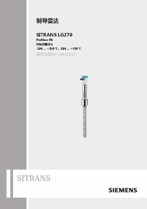
制导雷达SITRANS LG270 Profibus PA同轴测量探头-196 … +280 ℃; -196 … +450 ℃操作说明书 • 09/20172PBD-51041275SITRANS LG270 - 操作说明书44582-ZH-1710303PBD-51041275SITRANS LG270 - 操作说明书44582-Z H -171030目录1关于本文献资料 ............................................................................................................................................51.1 功能 .............................................................................................................................................................................51.2 对象 .............................................................................................................................................................................51.3 使用的标记.. (52)为了您的安全 ...............................................................................................................................................62.1 获得授权的人员.........................................................................................................................................................62.2 合规使用 .....................................................................................................................................................................62.3 谨防错误使用.............................................................................................................................................................62.4 一般安全提示.............................................................................................................................................................62.5 欧盟一致性.................................................................................................................................................................62.6 NAMUR 推荐 ............................................................................................................................................................62.7 在美国和加拿大进行安装和运行. (73)产品说明 ......................................................................................................................................................83.1 结构 .............................................................................................................................................................................83.2 作业方式 .....................................................................................................................................................................93.3 包装、运输和仓储 ..................................................................................................................................................103.4 附件与备件 (114)安装 ...........................................................................................................................................................124.1 一般提示 ...................................................................................................................................................................124.2 安装提示 . (125)与供电装置相连接 ......................................................................................................................................175.1 准备接线 ...................................................................................................................................................................175.2 连接 ...........................................................................................................................................................................175.3 单腔式外壳的接线图 ..............................................................................................................................................195.4 双腔式外壳的接线图 ..............................................................................................................................................195.5 设置仪表地址...........................................................................................................................................................205.6 启动阶段 . (216)用显示和调整模块进行调试 ........................................................................................................................226.1 使用显示和调整模块 ..............................................................................................................................................226.2 操作系统 ...................................................................................................................................................................236.3 参数化 - 快速调试 ..................................................................................................................................................246.4 参数化 - 扩展了的操作功能..................................................................................................................................246.5 对设置的参数数据的存储 .. (407)用 PACTware 进行调试 .............................................................................................................................417.1 连接计算机...............................................................................................................................................................417.2 通过 PACTware 设置参数.....................................................................................................................................417.3 通过快速调试来投入使用 ......................................................................................................................................427.4 对设置的参数数据的存储 ......................................................................................................................................438 用其它系统进行调试 ...................................................................................................................................448.1 DD 操作程序 (449)诊断与服务 .................................................................................................................................................459.1 维护 ...........................................................................................................................................................................459.2 诊断储存器...............................................................................................................................................................459.3 状态信息 ...................................................................................................................................................................459.4 排除故障 ...................................................................................................................................................................489.5 更换电子插件...........................................................................................................................................................509.6 软件升级 ...................................................................................................................................................................519.7 需要维修时的步骤 .. (51)10 拆卸 ...........................................................................................................................................................5210.1 拆卸步骤 . (52)4PBD-51041275SITRANS LG270 - 操作说明书44582-ZH-17103010.2 废物清除 ...................................................................................................................................................................5211 附件 .. (53)11.1 技术参数 ...................................................................................................................................................................5311.2 Profibus PA 通讯 ...................................................................................................................................................6311.3 尺寸 ...........................................................................................................................................................................6711.4 商标 (70)用于防爆区域的安全提示请在将仪表用于防爆应用领域时遵守专门针对防爆的安全说明。
CMA270 安装说明书

I N S T A L L A T I O N I N S T R U C T I O N SThreaded Pipe CouplerCMA270CMA270Installation Instructions2DISCLAIMERMilestone AV Technologies and its affiliated corporations and subsidiaries (collectively "Milestone"), intend to make thismanual accurate and complete. However, Milestone makes no claim that the information contained herein covers all details,conditions or variations, nor does it provide for every possible contingency in connection with the installation or use of this product. The information contained in this document is subject to change without notice or obligation of any kind. Milestone makes no representation of warranty, expressed or implied,regarding the information contained herein. Milestone assumes no responsibility for accuracy, completeness or sufficiency of the information contained in this document.Chief® is a registered trademark of Milestone AV Technologies.All rights reserved.IMPORTANT SAFETY INSTRUCTIONSWARNING: A WARNING alerts you to the possibility ofserious injury or death if you do not follow the instructions.CAUTION: A CAUTION alerts you to the possibility ofdamage or destruction of equipment if you do not follow the corresponding instructions.WARNING:Failure to read, thoroughly understand, andfollow all instructions can result in serious personal injury,damage to equipment, or voiding of factory warranty! It is the installer’s responsibility to make sure all components are properly assembled and installed using the instructions provided.WARNING:Failure to provide adequate structural strengthfor this component can result in serious personal injury or damage to equipment! It is the installer’s responsibility to make sure the structure to which this component is attached can support five times the combined weight of all equipment.Reinforce the structure as required before installing the component.WARNING:Exceeding the weight capacity can result inserious personal injury or damage to equipment! It is the installer’s responsibility to make sure the combined weight of all components located between the CMA270 up to (and including) the display/projector does not exceed 500 lbs (226.8 kg). The capacity of CMA270 may be limited to the lowest rated capacity of any component located between the CMA270 and the supporting structure!WARNING:Use this mounting system only for its intendeduse as described in these instructions. Do not use attachments not recommended by the manufacturer.WARNING:Never operate this mounting system if it isdamaged. Return the mounting system to a service center for examination and repair.WARNING:Do not use this product outdoors.--SAVE THESE INSTRUCTIONS--DIMENSIONSInstallation Instructions CMA2703TOOLS FOR INSTALLATION / PARTSINSTALLATIONWARNING:Exceeding the weight capacity can result inserious personal injury or damage to equipment! It is the installer’s responsibility to make sure the combined weight of all components attached to the CMA270 does not exceed 500 lbs (227 kg).•The capacity of CMA270 may be limited to the lowest rated capacity of any component located between the CMA270 and the supporting structure!1.Install 1-1/2" NPT or NPSM following ANSI/ASME B1.20.1(Schedule 40, 0.154" minimum thickness aluminum - ASTM B221) threaded extension columns (not included) into CMA270 (A) until tight, with a minimum of four threads engaged. (See Figure 1)2.Using hex keys (D or E), secure extension columns by one of the following methods (See Figure 1):•Install two 5/16-18" x 3/8" set screws (B) into threaded holes, tightening firmly against columns.•OPTIONAL: Install two 5/16-18" x 1/4" security set screws (C) into threaded holes, tightening firmly against columns.Figure 1CMA270Installation InstructionsUSA/InternationalA 6436 City West Parkway, Eden Prairie, MN 55344P 800.582.6480 / 952.225.6000F 877.894.6918 / 952.894.6918EuropeA Franklinstraat 14, 6003 DK Weert, Netherlands P +31 (0) 495 580 852F +31 (0) 495 580 845Asia PacificAOffice No. 1 on 12/F, Shatin Galleria 18-24 Shan Mei Street Fotan, Shatin, Hong Kong P 852 2145 4099F 852 2145 4477Chief Manufacturing, a products division of Milestone AV Technologies 8800-002185 Rev002013 Milestone AV Technologies, a Duchossois Group Company 04/13。
- 1、下载文档前请自行甄别文档内容的完整性,平台不提供额外的编辑、内容补充、找答案等附加服务。
- 2、"仅部分预览"的文档,不可在线预览部分如存在完整性等问题,可反馈申请退款(可完整预览的文档不适用该条件!)。
- 3、如文档侵犯您的权益,请联系客服反馈,我们会尽快为您处理(人工客服工作时间:9:00-18:30)。
B0700ARREV C I/ASeries ® SystemField Control Processor 270 (FCP270)User’s GuideMay 31, 2007Invensys, Foxboro, FoxCom, Spec 200, SPECTRUM and I/A Series are trademarks of Invensys plc, its subsidiaries, and affiliates.All other brand names may be trademarks of their respective owners.Copyright 2004-2007 Invensys Systems,Inc.All rights reservedContentsFigures (vii)Tables (ix)Preface (xi)Who This Book Is For (xi)What You Should Know (xi)Revision Information (xi)Reference Documents (xi)Glossary of Terms (xiii)1. Introduction (1)Overview (1)Features (2)Fault-Tolerance (3)Traditional Redundant Systems (3)FCP270 Fault-tolerant Operation (3)On-Line Image Update (4)FCP270 Network Configuration (4)Network Path Switching (4)Splitter/Combiner (4)Fieldbus Expansion Module 100 (FEM100) (6)I/O Communications (6)Communication to 200 Series Fieldbus Modules (7)Communication to Y-Module Fieldbus Modules (7)Time Synchronization (7)Overview (7)Internal Source Time Synchronization (7)External Source Time Synchronization (8)FCP270 Sizing Constraints (8)FCP270 Supported Block Processing Cycles (8)2. Installing the Field Control Processor 270 (9)Overview (9)System Definition (9)Installing a Single or Primary FCP270 Module (10)Installing a Shadow FCP270 Module (13)iiiB0700AR – Rev C ContentsCabling a Single (Non-Fault-Tolerant) FCP270 Module (14)Cabling a Fault-Tolerant FCP270 Module Pair (14)Boot-Up Sequence (18)Case 1 – Rebooting a Commissioned FCP270 (18)Case 2 – Connecting an FCP270 with the Same Letterbug (19)Case 3 – Connecting an FCP270 with a New Letterbug (19)Case 4 – Connecting a Shadow Module with Same Software Image (19)Case 5 – Connecting a Shadow Module with Different Software Image (19)Cabling Y-Module FBMs to an FCP270 Baseplate (20)Remote Fieldbus Extension, Cable Connections (20)3. Configuration Information (27)System Definition (27)System Definition Procedure (27)Integrated Control Configuration (28)Off-Line Control Configuration (29)On-Line Control Configuration (30)Available I/A Series System Control Blocks (30)4. System Management (31)Overview (31)Operating Status (31)System Management Displays for the FCP270 (31)Equipment Information Display for FCP270 (31)Configuration Information Display for FCP270 (36)Equipment Change Display for FCP270 (37)Reboot Station Procedure (39)Image Update Procedure for a Non-Fault-Tolerant FCP270 (39)Image Update Procedure for a Fault-Tolerant FCP270 (40)On-line Image Update Procedure for a Fault-Tolerant FCP270 (41)System Management Displays – Primary ECB (FBM0) (42)Equipment Information Display for Primary ECB (FBM0) (43)Equipment Change Display for Primary ECB (FBM0) (46)Overview of Fieldbus Switching Mode (48)Using the Fieldbus Switching Options (49)Overview of the General Download (49)Downloading all FBM Images (49)On-Line Diagnostics (PIO) Display for Primary ECB (FBM0) (50)5. Troubleshooting (53)Overview (53)LED Indicators, Reset Button, and Infrared Ports (53)Operational Status LED Indicators (55)FCP270 Troubleshooting (55)ivContents B0700AR – Rev C Using the Operational Status LEDs (56)Red off, Green off (56)Red on, Green off (56)Red on, Green on (57)Cycling Red, Red/Green (57)Red off, Green on (57)Using the Ethernet Tx and Rx/Link Status LEDs (58)Using the Fieldbus Tx and RX Status LEDs (58)Fault-Tolerant FCP270 Troubleshooting Addenda (58)Replacing a Failed Module (59)Memory Dumps and Last Gasp Messages (59)Last Gasp Messages (59)Memory Dumps (60)Diagnostics (61)Start-Up Diagnostics (61)Error Recovery Local Diagnostics (62)Error Recovery Cooperative Diagnostics (62)Appendix A. Upgrade Diagrams (63)Index (73)vB0700AR – Rev C Contents viFigures1-1.Typical FCP270 Network Configuration (Simplified) (5)2-1.FCP270 Module Installation (Typical) (10)2-2.Cabling the FCP270 Fault-tolerant Controllers (Two-Position Baseplate Example) (15)2-3.Cabling the FCP270 Fault-tolerant Controllers (Four-Position Baseplate Example) (16)2-4.Cabling Y-Module FBMs to an FCP270 Baseplate (21)2-5.TCA Cable Connection to 268 Kbps Fieldbus Splitter/Terminator (22)2-6.TCA Termination Block Assembly Mounting (22)2-7.TCA Termination Block Removal (23)2-8.Remote Redundant Fieldbus Cabling (FCP270 End) (24)2-9.Example of Extending Fieldbus in Two Directions from FCP270 (25)3-1.Typical Control Scheme Using an FCP270 and 200 Series FBMs (29)4-1.Equipment Information Display for FCP270 – Typical (1 of 2) (32)4-2.Equipment Information Display for FCP270 – Typical (2 of 2) (32)4-3.Configuration Information Display for FCP270 (36)4-4.Equipment Change Display for FCP270 (37)4-5.REBOOT STATION Dialogue Box – Fault-Tolerant FCP270 (39)4-6.IMAGE UPDATE Dialogue Box – Non-Fault-Tolerant FCP270 (40)4-7.IMAGE UPDATE Dialogue Box – Fault-Tolerant FCP270 (41)4-8.ON-LINE IMAGE UPDATE Dialogue Box – Fault-Tolerant FCP270 (41)4-9.REBOOT STATION Dialogue Box – Fault-Tolerant FCP270 (42)4-10.Equipment Information Display for Primary ECB (FBM0) – Typical (1 of 2) (43)4-11.Equipment Information Display for Primary ECB (FBM0) – Typical (2 of 2) (44)4-12.Equipment Change Display for Primary ECB (FBM0) (47)4-13.On-line Diagnostics Display for Primary ECB (FBM0) (50)5-1.FCP270 LED Indicators, Reset Button, and Infrared Port (54)A-1.Equipment Replacement Order for CP60-to-FCP270 Conversions (64)A-2.Converting CP10/30/40 with Local I/O to FCP270s (65)A-3.Converting CP60 with DCM10E to FCP270 (66)A-4.Converting CP60 with DCM10Ef to FCP270 (67)A-5.Converting CP60 with DCM10Ef with Fiber Optic Hub to FCP270 (68)A-6.Converting CP60 with FBI10E and 100Series FBMs to FCP270s (69)A-7.Converting CP60 with 200Series DIN Rail Mounted Equipment to FCP270 (70)A-8.Converting Micro-I/A Station to FCP270 (71)A-9.Converting AW51/AW70 to FCP270s (72)viiB0700AR – Rev C Figures viiiTables2-1.Cables for Connecting the FCP270 or Splitter/Combiners to the Ethernet Switches ..14 2-2.Cables for Connecting the Splitter/Combiners to the FCP270 (18)4-1.Equipment Information Display Fields for FCP270 (33)4-2.Configuration Information Display Fields for FCP270 (36)4-3.Equipment Change Display Fields for FCP270 (37)4-4.Equipment Information Display Fields for Primary ECB (FBM0) (44)4-5.Equipment Change Display Fields for Primary ECB (FBM0) (47)4-6.Equipment Change Display Fields for Primary ECB (FBM0) (50)5-1.FCP270 LED Indicators, Reset Button, and Infrared Communication Ports (54)5-2.FCP270 Operational Status LEDs (55)ixB0700AR – Rev C Tables xPrefaceThis document describes how to configure and install the Field Control Processor 270 (FCP270) in an I/A Series® system with The MESH control network. It also describes how the FCP270 functions in The MESH control network. Finally, it describes how to troubleshoot system prob-lems.Who This Book Is ForThis book is intended for the use of process control engineers and operators, instrument and maintenance engineers, and other qualified and authorized personnel involved in installing, configuring and maintaining the FCP270 for operation in the I/A Series MESH control network. What You Should KnowPrior to using this book, you should be generally familiar with the I/A Series system, and with DIN Rail Mounted FBM Subsystem User’s Guide (B0400FA). Detailed information relating to the various I/A Series software and hardware elements is found in the reference documents listed below.Revision InformationFor Revision C of this document, the following changes were made to this document:Chapter1 “Introduction”♦Added the Fieldbus Expansion Module 100 (FEM100) to the introduction and “Fieldbus Expansion Module 100 (FEM100)” on page6.♦Added “FCP270 Supported Block Processing Cycles” on page8.Chapter5 “T roubleshooting”♦Added “Memory Dumps” on page60.Appendix A “Upgrade Diagrams”♦Added the Appendix.Reference DocumentsThe following documents provide additional and related information.For information about defining control blocks and compounds, refer to:♦Integrated Control Block Descriptions (B0193AX)♦Integrated Control Software Concepts (B0700AG)For information about configuring and managing the FCP270, refer to:♦CP 270 On-Line Upgrade (B0700BY)♦System Definition: A Step-by-Step Procedure (B0193WQ)xiB0700AR – Rev C Prefacexii♦Letterbug Configurator User’s Guide (B0700AY)♦Integrated Control Configurator (B0193AV)♦I/A Series Configuration Component (IACC) User’s Guide (B0400BP)♦Process Operations and Displays (B0700BN)♦System Management Displays (B0193JC)♦Field Control Processor 270 (FCP270) Sizing Guidelines and Excel Workbook (B0700AV).For information about associated DIN Fieldbus Modules and the Fieldbus Expansion Module 100, refer to:♦DIN Rail Mounted FBM Subsystem User’s Guide (B0400FA).For information about Y-module Fieldbus Modules, refer to:♦I/A Series System Equipment Installation (B0193AC).For information about system power and earthing (grounding), refer to:♦Power, Earthing (Grounding), EMC and CE Compliance (B0700AU)For information about supported migration products, refer to:♦SPECTRUM™ Migration Integrator User's Guide (B0193RC)♦SPEC 200™ Control Integrator User's Guide (B0193RD)♦SPEC 200 MICRO™ Control Integrator User's Guide (B0193RR)♦SPEC 200 CCM Control Integrator User's Guide (B0193VU)♦DCS Fieldbus Modules for Westinghouse® WDPF Systems User's Guide (B0400BA).♦DCS Fieldbus Modules for APACS+™ Automation Systems User’s Guide (B0700BK)♦DCS Fieldbus Modules for Honeywell® TDC 2000 Systems User’s Guide (B0193VL)♦DCS Fieldbus Modules for Honeywell TDC 3000 Systems User’s Guide (B0193YW)♦DCS Fieldbus Modules for Bailey® NET90 and INFI90® Systems User’s Guide (B0193XG)♦DCS Fieldbus Modules for Fisher PROVOX® Series 10 Systems User’s Guide (B0193WV)♦DCS Fieldbus Modules for Fisher PROVOX Series 20 Systems User’s Guide (B0193YV)♦DCS Fieldbus Modules for Fisher PROVOX Controller Series Systems User’s Guide (B0400AR)For information about The MESH control network, refer to:♦The MESH Control Network Architecture Guide (B0700AZ)Most of these documents are available on the I/A Series Electronic Documentation CD-ROM (K0173TQ or K0173WT). The latest revisions of each document are also available through our Global Product Support at .Preface B0700AR – Rev C Glossary of TermsThe following terminology, used throughout this user’s guide, relates to the FCP270 controller and associated equipment.Name MeaningAI Analog inputAPACS+™Siemens® Process Automation SystemAW Application WorkstationBPC Block Processing CycleCP60Control Processor 60CSD Control Strategy DiagramDIN DIN is a non-governmental organization established to promote thedevelopment of standardization and related activities in Germany.ECB Equipment Control BlockEEPROM Electrically erasable programmable read-only memoryFBM I/A Series system Fieldbus ModuleFCM Fieldbus Communication ModuleFCP270Field Control Processor 270FDSI Foreign Device Systems IntegratorFEM Fieldbus Expansion ModuleGMT Greenwich Meridian Time (GMT) is an international time standard GPS Global positioning systemHART HART Field Communications Protocol is a standard for digitallyenhanced 4 to 20 mA smart instrument communication.HDLC High-level Data Link Control protocol - Master/Slave Protocol used ontop of several physical layers for FBM communicationI/A Series®Intelligent Automation SeriesIACC I/A Series Configuration ComponentICC Integrated Control ConfiguratorIR InfraredLC Connector for fiber optic cable connection to the ZCP270 orsplitter/combinerLED Light-emitting diodeLetterbug Alphanumeric string that the user defines to identify a station in anI/A Series control system.Letterbug Configurator Handheld device for setting, modifying and reading the controllerletterbug and reading controller status informationMMF Multimode fiber cableMTK Master TimekeeperMT-RJ Connector for fiber optic cable connection to Ethernet switchesxiiiB0700AR – Rev C PrefaceName MeaningROM Read only memoryRx ReceiveSMDH System Management Display Handler, the user interface for equipmentstatus and change actionsSOE Sequence of EventsSTK Slave TimekeeperSysDEF System DefinitionTDA T ransient Data AnalyzerTDR T ransient Data RecorderThe MESH The MESH Control NetworkTx T ransmitUTC Universal Coordinated Timexiv1. IntroductionThis chapter describes the main features, fault-tolerant operation, network configuration, and time synchronization of the Field Control Processor 270.OverviewThe Field Control Processor 270 (FCP270) is an optionally fault-tolerant station that performs regulatory, logic, timing, and sequential control together with connected Fieldbus Modules (FBMs) and other process interface devices. It also performs data acquisition (via the FBMs and/or other devices) and alarm detection and notification.The FCP270 supports process control via the standard 2 Mbps HDLC fieldbus for the following products:♦All DIN rail mounted 200 Series FBMs (FBM201, FBM202, and so forth). The FCP270 supports up to 32modules itself, and supports up to 128 modules whenused with a Fieldbus Expansion Module 100 (FEM100); based on the loading ofFCP270. Refer to Field Control Processor 270 (FCP270) Sizing Guidelines and ExcelWorkbook (B0700AV).♦Field Device Systems Integrator (FDSI) modules (FBM230/231/232/233)♦DCS Fieldbus Modules for APACS+™ Automation Systems♦DCS Fieldbus Modules for Westinghouse® WPDF SystemsThe FCP270 also supports process control via the optional 268 Kbps HDLC fieldbus for the fol-lowing products:♦All Y-module FBMs, also known as 100 Series FBMs (FBM01, FBM02, and so forth) – up to 64 modules, via an extended fieldbus♦Fieldbus Cluster I/O via FBP10 fieldbus processor module♦Foxboro Hydrostatic Interface Unit (HIU)♦Foxboro Mass Flowmeter♦Foxboro Panel Display Stations♦SPECTRUM™ Migration Integrators♦SPEC 200™ Control Integrators♦SPEC 200 MICRO™ Control Integrators♦SPEC 200 CCM Control Integrators♦DCS Fieldbus Modules for Honeywell® TDC 2000 and TDC 300 Systems♦DCS Fieldbus Modules for Bailey® Net90 and Infi90 Systems♦DCS Fieldbus Modules for Fisher’s PROVOX® Series 10, Series 20, and Controller Series Systems.1B0700AR – Rev C 1. Introduction2NOTEThe FCP270 supports either the 2 Mbps or the 268 Kbps HDLC fieldbus, but not both at the same time. For the maximum number of devices supported by each fieldbus, refer to the device specific Product Specification Sheets.FeaturesThe FCP270 provides the following new features and improvements.♦ A direct 100 Mbps Ethernet fiber connection to the The MESH control network for high speed data communication that is immune to electromagnetic interference overthe distance of the fiber cable.♦ A fault-tolerant option that delivers improved availability and safety using unique, dual controller comparison on all outgoing messages.♦On-line image update replaces the executable image (operating system) of a running, fault-tolerant FCP270 controller with a newer image without having to shut downthe equipment being controlled by the FCP270.♦Hardened, field-mounted control (100 Mbps Ethernet fiber controller, 2Mbps fieldbus, Series200 DIN rail mounted FBMs, Termination Assemblies, andFPS400-24 power supply). The new configuration eliminates the need for a rackroom (you only need a control room and a field enclosure).♦Supports up to 128 Series200 DIN rail mounted FBMs, or equivalent modules (depending on the sizing guidelines), when connected to an optional Fieldbus Expan-sion Module 100 (FEM100).♦Connection to Ethernet or serial devices via FDSIs which allows for new device interfaces. The FDSIs include FBM230, FBM231, FBM232, and FBM233.♦Optional global positioning system allows external time synchronization.♦Sequence of Events (SOE) are optionally time stamped at the FBM (200 Series FBMs only) to 1 ms1 accuracy throughout the system for later analysis of events.♦Optional T ransient Data Recorder (TDR) allows 10 ms sampling of analog data for later analysis of events using T ransient Data Analyzer (TDA). TDR data is optionallytime stamped (200 Series FBMs only) to 1 ms1 accuracy.♦Infrared interface to the I/A Series system Letterbug Configurator allows setting and reading the controller letterbug.♦Memory resident image for fast station reboot. Reboot time is less than 10 seconds.♦Improved controller performance. Block executions/second is 10,000 for the FCP270 compared to 3400 for the CP60.♦Up to 4000 blocks can be configured for the FCP270 (or fault-tolerant FCP270 pair)♦ A scalable license lets you start small with a full-featured control system. You can grow your system over time.♦Alarm enhancements to the function blocks: re-alarming on changes to alarm priority, re-alarming based on time, alarm suppression based on time.1. Time stamping has 1 ms accuracy only when using the optional GPS external time synchronization.1. Introduction B0700AR – Rev C3♦Foundation Fieldbus, FoxCom™, HART, Profibus, and Modbus FBMs are supported.♦Y-module FBMs and DCS migration FBMs are supported.♦For enhanced reliability during maintenance operations, a recessed reset button, located at the front of the module, allows you to manually reset the module without removing it from the baseplate.Fault-ToleranceFault-tolerant operation is unique with Foxboro control processors and uses patented technology. Fault-tolerance is superior to redundancy because outgoing messages from the fault-tolerant controller must be identical in both modules for a message to transmit successfully.The following sections describe the difference between redundancy and fault-tolerance from an applications standpoint and how fault-tolerance is implemented using the FCP270.Traditional Redundant SystemsT raditionally, the goal of improved availability through redundancy has been achieved using a second, or “backup” controller. Redundant systems that use a secondary controller may have the following shortcomings:♦Problems with the primary controller are not detected or are only detected after a number of potentially bad messages have been transmitted to the field.♦Secondary controllers may not use the latest “good” data when they take over from the primary controller. Configuring the secondary controller correctly can result in substantial system downtime.♦Secondary controllers may have health problems that are hard to determine after they have been idle for a long period of time.T o remove these shortcomings from critical systems, the FCP270 uses a patented method of fault-tolerance.FCP270 Fault-tolerant OperationThe fault-tolerant version of the FCP270 consists of two modules operating in parallel, with two separate connections to the The MESH control network. The two control processor modules, married together as a fault-tolerant pair, provide continuous operation of the unit in the event of virtually any hardware failure occurring within one module of the pair.Both modules receive and process information simultaneously, and faults are detected by the modules themselves. One of the significant methods of fault detection is comparison of communication messages at the module’s external interface. Upon detection of a fault, thecommunication message is aborted, and self-diagnostics are run by both modules to determine which module is defective. The non-defective module then assumes control without affecting normal system operations. An aborted control network communication message is then sent by the non-defective module via the retry mechanisms of the communications protocol. An aborted fieldbus communication message is retried on the next BPC. For more information, see “Diagnos-tics” on page 61.B0700AR – Rev C 1. Introduction On-Line Image UpdateFor a fault-tolerant FCP270 controller, on-line image update replaces the executable image (oper-ating system) of a running FCP270 with a newer image without having to shut down the equip-ment being controlled by the FCP270. This feature allows you to take advantage of product enhancements while interrupting process control for only 1.5 seconds, approximately.Because the FCP270 contains its executable image in internal flash memory, and has sufficient RAM to hold a new executable image at the same time, on-line image updates are now much easier to perform.FCP270 Network ConfigurationThe MESH control network uses redundant communication paths to enhance control reliability.Figure1-1 shows a simplified FCP270 network configuration using redundant Ethernet fiber switches, 100Mbps fiber cables, splitter/combiners, FCP270 controllers (fault-tolerant), and redundant 2 Mbps fieldbus and redundant 268 Kbps fieldbus. Multiple FCP270s can share the same redundant switch.The FCP270 uses 100 Mbps Ethernet fiber connections to communicate with I/A Seriesworkstations connected to Ethernet switches in The MESH. For information about general guidelines and specific requirements for designing The MESH above the FCP270 level, including site planning and network installation guidelines, see The MESH Control Network Architecture Guide (B0700AZ).For instructions on installing and cabling the FCP270 in the non-fault-tolerant and fault-tolerant configurations, see Chapter2 “Installing the Field Control Processor 270”.Network Path SwitchingThe MESH control network provides redundant communications paths. The MESH architecture and the software in the controller allow it to switch paths when a communications path fails or when replacing modules.Each FCP270 has two station MAC addresses and two IP addresses, which are not embedded in hardware. When you replace the controller, the new controller acquires its station MAC and IP addresses from the system configuration file based on its assigned letterbug. Software on the FCP270 then selects the network path that is used to transmit outbound communication. Splitter/CombinerFault-tolerant FCP270s require a pair of splitter/combiners, one to connect to each of The MESH control network paths (see Figure1-1). Non-fault-tolerant FCP270s can optionally use splitter/combiners to provide for a future upgrade to fault-tolerant operation. The splitter/combiner has three 100 Mbps connections: one to the primary module of a fault-tolerant pair, one to the shadow module, and one to The MESH. One splitter/combiner in the pair is con-nected to one Ethernet switch, the other is connected to another Ethernet switch.The splitter/combiner is connected via fiber optic cables. Inbound traffic from The MESH is split and sent to each FCP270 controller. Output traffic is sent from the primary module, which can be either physical module, to The MESH.41. Introduction B0700AR – Rev C5Figure 1-1. Typical FCP270 Network Configuration (Simplified)* Splitter/Combiner.Note: For additional sizing information, refer to Field Control Processor 270 (FCP270) SizingThe MESH Control NetworkGuidelines (B0700AV).Up to 64 Y -module FBMs per FCP270 or FCP270 Pair(See Note below and “Overview” on page 1)B0700AR – Rev C 1. Introduction6Fieldbus Expansion Module 100 (FEM100)When an FCP270 is connected to a Fieldbus Expansion Module 100 (FEM100), the FEM100 increases the number of 200 Series (or equivalent) FBMs supported up to 128 FBMs. (Refer to Field Control Processor 270 (FCP270) Sizing Guidelines and Excel Workbook (B0700AV) to deter-mine actual sizing for your system.)The FCP270 requires a software level 8.3 or higher to support the FEMs.The FEM100 generates four single fieldbus ports, or Expanded Fieldbus1 through 4. Each Expanded Fieldbus is capable of communicating with up to thirty-two FBMs. The FEM100 and Expanded Fieldbuses are transparent to the 2Mbps HDLC Module Fieldbus between theFCP270 and the 200 Series (or equivalent) FBMs.A pair of FEM100s provides redundancy for both paths of the redundant 2Mbps HDLC module fieldbus network. Both FEM100s are always active. In case of a module’s failure, the other pro-vides backup coverage until the failed module is returned to service. The failure is reported as an interruption to one path of the redundant fieldbus network.Additional information on the FEM100 is provided in the DIN Rail Mounted FBM Subsystem User’s Guide (B0400FA).I/O CommunicationsThe FCP270 contains several I/O communication features and functions:♦Dual channel HDLC at either 2 Mbps or 268 Kbps for redundant fieldbus connec-tion to the FCP270 module♦Simultaneous support of 200 Series FBM types and protocols (HART, Foundation Fieldbus, Profibus, Modbus, FoxCom, FDSI and standard 200 Series FBMs)♦ A maximum of 32 DIN railed mounted 200 Series FBMs is allowed per 2 Mbps HDLC fieldbus. The FEM100 provides four Expanded Fieldbuses, which supportsup to 128 200Series FBMs (or equivalent modules) per FCP270.♦ A maximum of 39 Siemens APACS+ DCS migration FBMs is allowed on the 2 Mbps HDLC fieldbus. The FEM100 provides two Expanded Fieldbuses, which supports upto 78 Siemens APACS+ DCS migration FBMs per FCP270.♦ A maximum of 36 Westinghouse DCS migration FBMs is allowed on the 2 Mbps HDLC fieldbus. The FEM100 provides two Expanded Fieldbuses, which supports upto 72 Westinghouse DCS migration FBMs per FCP270.♦ A maximum of 64 Y-module FBMs and/or DCS migration FBMs is allowed on the 268 Kbps fieldbus.I/O communications support the following multiple data streams:♦Real-time I/O♦AI Stream data for the TDR♦Sequence of Events (SOE) data2♦I/O maintenance activity♦Pass-through activity for device configuration, and so forth.2. Using the new SOE feature or the original SOE via ECB6.1. Introduction B0700AR – Rev C Communication to 200 Series Fieldbus ModulesThe 200 Series DIN rail mounted FBMs connect to the optionally-fault-tolerant FCP270through the baseplate. The 2 Mbps HDLC fieldbus is connected to both paths of the redundant fieldbus network, providing continuous communication in the event one path fails (seeFigure1-1).For complete information on DIN Rail mounted devices, see DIN Rail Mounted FBM Subsystem User’s Guide (B0400FA).Communication to Y-Module Fieldbus ModulesThe Y-module FBMs connect to the optionally-fault-tolerant FCP270 through the baseplate. The 268 Kbps HDLC fieldbus is connected to both paths of the redundant fieldbus network, provid-ing continuous communication in the event one path fails (see Figure1-1). The fieldbus connects to the baseplate via the P0926LC adapter and the P0903VY termination cable assembly (TCA). A 268 Kbps Splitter/T erminator connects the extended fieldbus to 2- position FCP270 only modu-lar baseplate. This splitter/terminator does not support time strobe signals. The extended fieldbus can be up to 1 Km (3200 ft) in length.For complete information on DIN Rail mounted devices, see DIN Rail Mounted FBM Subsystem User’s Guide (B0400FA).Time SynchronizationThe I/A Series system supports time synchronization using either an optional, externallymaintained source of Universal Coordinated Time (UTC) from GPS satellites or an internal source using proprietary software.Time synchronization within an I/A Series system synchronizes controllers to provide accurate timestamps for event and data reporting throughout the system. Time stamping is used for SOE evaluation, TDA, and alarm messages.OverviewA Master Timekeeper (MTK), residing in an Application Workstation (AW), maintains the timesource and distributes the system time to all other stations in The MESH control network. A Slave Timekeeper (STK) receives time information from the MTK and keeps itself synchronized with the MTK, and thus with all other stations in The MESH. STKs reside in all controllers.The MTK determines the time for synchronizing all slave stations by using either the AW’sreal-time clock (internal time source) or the optional GPS receiver and time strobe generator (external time source).For complete information on time synchronization, refer to Time Synchronization User’s Guide (B0700AQ).Internal Source Time SynchronizationFor internal source time synchronization (standard), the MTK station uses time from the internal clock in the hosting PC. The MTK distributes time as UTC to all stations in The MESH. This time is displayed as local time.。
