4VPC_1999大兜风手册
Hurricane Haze 4D 用户手册说明书
User ManualT ABLE OF C ONTENTS1. Before You Begin (1)What Is Included (1)Unpacking Instructions (1)Claims (1)Text Conventions (1)Symbols (1)Disclaimer (1)Product at a Glance (2)Safety Notes (2)2. Introduction (3)Product Overview (3)Product Dimensions (3)3. Setup (4)AC Power (4)Fuse Replacement (4)Mounting (5)Orientation (5)Rigging (5)4. Operation (6)Hurricane Haze 4D Control Priority (6)Control Panel Operation (6)Manual Control Knobs (6)Menu Map (6)Configuration (DMX) (6)Starting Address (6)DMX Channel Assignments and Values (6)Wired Timer Remote Setup (7)Wired Timer Remote Operation (7)5. Maintenance and Storage (8)Hazer Maintenance (8)Storage (8)6. Technical Specifications (9)7. Returns (10)7. Contact Us (11)1. B EFORE Y OU B EGINWhat Is IncludedUnpacking InstructionsCarefully unpack the product immediately and check the container to make sure all the parts are in the package and are in good condition.ClaimsIf the box or the contents (the product and included accessories) appear damaged from shipping, or show signs of mishandling, notify the carrier immediately, not Chauvet. Failure to report damage to the carrier immediately may invalidate your claim. In addition, keep the box and contents for inspection.For other issues, such as missing components or parts, damage not related to shipping, or concealed damage, file a claim with Chauvet within 7 days of delivery.Text ConventionsSymbolsDisclaimerChauvet believes that the information contained in this manual is accurate in all respects. However,Chauvet assumes no responsibility and specifically disclaims any and all liability to any party for any loss, damage or disruption caused by any errors or omissions in this document, whether such errors oromissions result from negligence, accident or any other cause. Chauvet reserves the right to revise the content of this document without any obligation to notify any person or company of such revision, however, Chauvet has no obligation to make, and does not commit to make, any such revisions. Download the latest version from .The works of authorship contained in this manual, including, but not limited to, all design, text and images are owned by Chauvet.© Copyright 2016 Chauvet & Sons, LLC. All rights reserved.Electronically published by Chauvet in the United States of America.CHAUVET, the Chauvet logo, and Hurricane Haze 4D are registered trademarks or trademarks of Chauvet & Sons LLC (d/b/a Chauvet and Chauvet Lighting) in the United States and other countries. Other company and product names and logos referred to herein may be trademarks of their respective companies.•Hurricane Haze 4D •Power Cord•Wired Timer Remote•Hanging Bracket with Mounting Hardware •Warranty Card•Quick Reference GuideProduct at a Glance•Not intended for permanent installations.•Always connect the product to a grounded circuit to avoid the risk of electrocution.•Always disconnect this product from the power source before cleaning it or replacing the fuse.•Make sure the power cord is not crimped or damaged.•Never disconnect the power cord by pulling or tugging on the cord.•If mounting this product overhead, always secure it to a fastening device using a safety cable.•Do not mount this product on a flammable surface (e.g., wood, linoleum, carton, plastic, or carpet).•Make sure there are no flammable materials close to the unit while operating•Do not touch the output nozzle on this product. It is very hot during operation and it may remain hot for several hours after turning the unit off.•Do not drink the haze fluid. If you do, call your local emergency service (911 in the US) for help.•Do not add perfume, alcohol, gasoline, or any other flammables to the haze fluid.•Depending on the amount of haze generated, all haze machines may set off smoke detectors.•In certain environments, haze fluid-based machines may leave a slippery residue on floors and surfaces.•Do not use for space heating purposes.•Use only CHAUVET DJ water-based haze fluid.•Drain the tank before transporting the product.•Always make sure that the voltage of the outlet to which you are connecting the product is within the range stated in the decal or rear panel of the product.•This product is for indoor use only! To prevent risk of fire or shock, do not expose this product to rain or moisture.•Always install this product in a location with adequate ventilation, at least 20 in (50 cm) from adjacent surfaces.•Be sure that no ventilation slots on the unit’s housing are blocked.•Never connect this product to a dimmer or rheostat.•Make sure to replace the fuse with another of the same type and rating.•Never carry the product from the power cord or any moving part. Always use the hanging/ mounting bracket.•The maximum ambient temperature (Ta) is 104 °F (40 °C). Do not operate this product at higher temperatures.•In the event of a serious operating problem, stop using the product immediately.•Never try to repair this product. Repairs carried out by unskilled people can lead to damage or malfunction. Please contact the nearest authorized technical assistance center.•To eliminate unnecessary wear and improve its lifespan, during periods of non-use completely disconnect the product from power via breaker or by unplugging it.Keep this User Manual for future use. If you sell the product, be sure that the purchaser receives this document.2. I NTRODUCTIONProduct OverviewProduct DimensionsFluid TankBlower FanDMX In/OutHaze Output KnobRemote InPower SwitchPower In Fuse HolderFan Speed KnobMenu ButtonsLED Display3. S ETUPAC PowerThe Hurricane Haze 4D has a fixed voltage power supply and it can work with an input voltage of either 120 VAC, 60 Hz or 230 VAC, 50 Hz, depending on the specific model.To determine the product’s power requirements (circuit breaker, power outlet, and wiring), use the current value listed on the label affixed to the product’s back panel, or refer to the product’s specifications chart. The listed current rating indicates the product’s average current draw under normal conditions.Fuse Replacement1.Wedge the tip of a flat-head screwdriver into the slot of the fuse holder.2.Pry the fuse holder out of the housing.3.Remove the blown fuse from the holder and replace with a fuse of the exact same type and rating.4.Insert the fuse holder back in place and reconnect power.•Always connect the product to a protected circuit (a circuit breaker or fuse).Make sure the product has an appropriate electrical ground to avoid the risk of electrocution or fire.•To eliminate unnecessary wear and improve its lifespan, during periods of non-use completely disconnect the product from power via breaker or by unplugging it.Never connect the product to a rheostat (variable resistor) or dimmer circuit, even if the rheostat or dimmer channel serves only as a 0 to 100% switch.Disconnect the product from the power outlet before replacing the fuse.Safety capSpare fuse holder(inside safety cap)Installed fuse(held by plastic clip)MountingBefore mounting the product, read and follow the safety recommendations indicated in the Safety Notes .OrientationRigging•Before deciding on a location, always make sure there is easy access to the product for maintenance and fluid replenishment.•Make sure adequate ventilation is provided around the product.•Make sure that the structure or surface onto which you are mounting the product can support the product’s weight. (see the Technical Specifications )•When mounting the product overhead, always use a safety cable. Mount the product securely to a rigging point, such as an elevated platform or a truss.•When rigging the product onto a truss, you should use a mounting clamp of appropriate weight capacity. The bracket has 13-mm holes, which are appropriate for this purpose.•The rubber feet also serve as floor supports and allow for surface mounting. When mounting the product on the floor, make sure that the product and cables are away from people and vehicles.Mounting DiagramThis product may NOT be tilted. This product should be level when on a surface or when mounted.While operating the Hurricane Haze 4D, make sure there is adequate haze fluid in the machine to prevent pump and heater damage. When the haze fluid levelbecomes low, simply add more haze fluid to continue using the Hurricane Haze 4D.Mounting BracketSafety Cable(such as CH-05 fromChauvet)Mounting Clamp(such as CLP-15 or CLP-15Nfrom Chauvet)BracketAdjustable ScoopFluid Level IndicatorRubber Feet for Floor Mounting(x4)4. O PERATIONHurricane Haze 4D Control PriorityThe Hurricane Haze 4D operates according to the following priority control levels:Control Panel OperationTo access the control panel functions, use the four buttons located underneath the display, and the two manual control knobs located to the right of the display. Please refer to the Product Overview to see the button and knob locations on the control panel.Manual Control KnobsThe manual control knobs allow for operation of the Hurricane Haze 4D without a controller.Configuration (DMX)The Hurricane Haze 4D works with a DMX controller. Information about DMX is in the CHAUVET DMX Primer, which is available from the Chauvet website/downloads/DMX_Primer_rev05_WO.pdf .Starting AddressWhen selecting a starting DMX address, always consider the number of DMX channels the selected DMX mode uses. If you choose a starting address that is too high, you could restrict the access to some of the product’s channels.The Hurricane Haze 4D uses 2 DMX channels, which defines the highest configurable address to 511.If you are not familiar with the DMX protocol, download the DMX Primer from .To select the starting address, do the following:1.Press <MENU> repeatedly until d _ _ _shows on the display.e <UP> or <DOWN> to select the starting address.3.Press <ENTER>.DMX Channel Assignments and Values1. A DMX controller takes the highest priority, and will override both the Wired TimerRemote and the manual control knobs.2.The manual control knobs will override the Wired Timer Remote, but not a DMXcontroller.3.The Wired Timer Remote has the lowest priority.Wired Timer Remote SetupThe Wired Timer Remote allows you to automatically trigger haze output by setting output, interval time, and duration time. LED indicator lights display the machine and controller’s current state. Rotary knobs set interval, output, and duration times, while manual and continuous buttons allow overriding control.1.Plug in the haze machine to power.2.Plug in the wired timer controller to the Remote socket on the back of the haze machine. (See theProduct Overview .)3.Allow the Hurricane Haze 4D three to four minutes to heat up before continuing.Wired Timer Remote OverviewWired Timer Remote OperationThe Wired Timer Remote has three modes of operation: timer, continuous, and manual.Timer ModeTo trigger the Hurricane Haze 4D with the timer function, follow the instructions below:1.Set the desired output level with the OUTPUT knob.2.Set the INTERVAL and DURATION knobs to the desired positions.•The INTERVAL knob sets the amount of time in between bursts of haze.•The DURATION knob sets the length of time that the haze machine will run during the burst.3.Press the <TIMER ON/OFF> latching button. The LED indicator above the button will light up.The timer will now run as set by the INTERVAL , DURATION , and OUTPUT knobs.4.Press the <TIMER ON/OFF> button again to turn off the timer.Continuous ModeTo trigger the Hurricane Haze 4D to continuously cycle haze, follow the instructions below:1.Set the desired output level with the OUTPUT knob.2.Press the <CONTINUOUS> latching button. The LED indicator above the button will light up. Thehaze machine outputs haze until the <CONTINUOUS> button is pressed again.3.Press the <CONTINUOUS> button again to stop the haze output.Manual ModeTo trigger the Hurricane Haze 4D manually, do the following:1.Set the desired output level with the OUTPUT knob.2.Press and hold the <MANUAL> button on the Wired Timer Remote. The LED indicator above thebutton will light up. The haze machine will output haze for as long as you hold down the <MANUAL> button.3.Release the <MANUAL> button to stop the haze output.The MANUAL Button will override the timer function.•The duration of Continuous haze output is based on the capacity of the tank.•Fluid consumption will be significantly increased during Continuous mode.INTERVAL KnobOUTPUT Knob TIMER ON/OFF Button DURATION KnobMANUAL ButtonCONTINUOUS Button5. M AINTENANCE AND S TORAGEHazer MaintenanceDo not allow the hazer to become clogged. After every 40 hours of continuous operation, use CHAUVET Fog Cleaner Quart (FCQ) through the system to prevent the accumulation of particulate matter in the heating element.The recommended cleaning procedure is as follows.1.Unplug the product from power.2.Empty all haze fluid from the machine.3.Add cleaning solution to the tank.4.Connect the product to power and allow it to warm up.5.Run the unit in a well-ventilated area until the tank is almost empty. Do not allow the pump to rundry.6.Refill with haze fluid to continue using the hazer. Run the machine briefly to clear any remainingcleaning solution from the pump and heater.StorageBefore storing the hazer, run FCQ through the system as described in the cleaning procedure above; however, only follow steps 1 through 5. Do not refill the tank with haze fluid if storing the hazer . Cleaning the system prior to storage will help prevent any particles from condensing inside the pump or heater while not in use.Powering off the unit for transportFollow these instructions to prevent leaks, and allow the air pump to entirely clear the fluid line and heater of the haze fluid before power off.Do Not operate the machine without fluid at any time.Fog Cleaner Quart (FCQ) was specifically developed by Chauvet to clean your Hurricane Haze 4D. Make sure you use FCQ regularly, no longer than 90 days between cleanings, to increase the life of your product.Test-run your Hurricane Haze 4D on a monthly basis to achieve the best performance.To prevent spills or leaks before, during, or after transport, Chauvet recommends the following steps for your Hurricane Haze 4D:1.Turn the "Haze Volume " output to off.2.Wait 30-45 seconds.3.When there is no more haze fluid in the output line, turn off the machine by pressingthe power switch.6. T ECHNICAL S PECIFICATIONSDimensions and WeightNote : Dimensions in inches rounded to the nearest decimal digit.PowerOperationFog OutputThermalDMXOrderingL ENGTHW IDTHH EIGHTW EIGHT 11 in (277 mm)15.5 in (396 mm)9.6 in (245 mm)13.2 lb (6 kg)P OWER S UPPLY T YPER ANGEV OLTAGE S ELECTIONModel-specific 120 VAC, 60 Hz, or 230 VAC, 50 HzFixed P ARAMETER 120 V, 60 H Z 230 V, 50 H Z Consumption 1120 W 1120 W Operating Current8.1 A 4.8 A Fuse F 15 A, 250 V F 15 A, 250 V P OWER I/OU.S./W ORLDWIDEUK/E UROPEPower input connector IECIEC Power Cord plugEdison (U.S.)Local Plug H EAT -U P T IMET ANK C APACITY F LUID C ONSUMPTION2 min9 gal (3.75 l)10 ml/minO UTPUT 4300 cfmM AXIMUM E XTERNAL T EMPERATUREC OOLING S YSTEM104 °F (40 °C)Convection I/O C ONNECTORC HANNEL R ANGE3-pin XLR2P RODUCT N AMEITEM CODE UPC N UMBER Hurricane Haze 4D (120 V)05071211781462215590Hurricane Haze 4D (230 V)05071212781462215606R ETURNSIn case you need to get support or return a product:•If you are located in the U.S., contact Chauvet World Headquarters.•If you are located in the UK or Ireland, contact Chauvet Europe Ltd.•If you are located in Mexico, contact Chauvet Mexico.•If you are located in Benelux, contact Chauvet Europe BVBA.•If you are located in any other country, DO NOT contact Chauvet. Instead, contact your localdistributor. See for distributors outside the U.S., UK, Ireland, Mexico, or Benelux.Call the corresponding Chauvet Technical Support office and request a Return Merchandise Authorization (RMA) number before shipping the product. Be prepared to provide the model number, serial number, and a brief description of the cause for the return.Send the merchandise prepaid, in its original box, and with its original packing and accessories. Chauvet will not issue call tags.Clearly label the package with the RMA number. Chauvet will refuse any product returned without an RMA number.Before sending the product, clearly write the following information on a piece of paper and place it inside the box:•Your name •Your address •Your phone number •RMA number • A brief description of the problemBe sure to pack the product properly. Any shipping damage resulting from inadequate packaging will be your responsibility. FedEx packing or double-boxing are recommended.If you are located outside the U.S., UK, Ireland, Mexico, or Benelux, contact yourdistributor of record and follow their instructions on how to return Chauvet products to them. Visit our website for contact details.Write the RMA number on a properly affixed label. DO NOT write the RMA number directly on the box.Chauvet reserves the right to use its own discretion to repair or replace returnedproduct(s).C ONTACT U SVisit the applicable website above to verify our contact details and instructions to request support.Outside the U.S., United Kingdom, Ireland, Mexico or Benelux, contact the dealer of record.Sunrise, FL 33351Fax: (954) 756-8015Voice: (954) 577-4455Email: ************************Fax: (954) 929-5560Toll Free: (800) 762-1084Email: *************************9770 KruishoutemBelgiumwww.chauvetlighting.euVoice: +32 9 388 93 97Email: **************************Brookhill Road Industrial EstatePinxton, Nottingham, UKNG16 6NTVoice: +44 (0) 1773 511115Fax: +44 (0) 1773 511110Industrial LermaEmail: ********************.mxLerma, Mexico C.P . 52000Voice: +52 (728) 285-5000.mx。
芝麻坊 4 系列电脑电源说明书
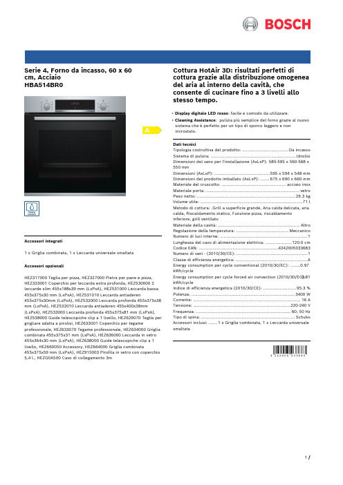
Serie 4, Forno da incasso, 60 x 60cm, AcciaioHBA514BR0Accessori integrati1 x Griglia combinata, 1 x Leccarda universale smaltataAccessori opzionaliHEZ317000 Teglia per pizza, HEZ327000 Pietra per pane e pizza, HEZ333001 Coperchio per leccarda extra profonda, HEZ530000 2 leccarde slim 455x188x39 mm (LxPxA), HEZ531000 Leccarda bassa 455x375x30 mm (LxPxA), HEZ531010 Leccarda antiaderen455x375x30mm (LxPxA), HEZ532000 Leccarda profonda 455x375x38 mm (LxPxA), HEZ532010 Leccarda antiaderen 455x400x38mm (LxPxA), HEZ533000 Leccarda profonda 455x375x81 mm (LxPxA), HEZ538000 Guide telescopiche clip a 1 livello, HEZ629070 Teglia per grigliare adatta a pirolisi, HEZ633001 Coperchio per tegame professionale, HEZ633070 Tegame professionale, HEZ634000 Griglia combinata 455x375x31 mm (LxPxA), HEZ636000 Leccarda in vetro 455x364x30 mm (LxPxA), HEZ638000 Guide telescopiche clip a 1 livello, HEZ660050 Accessory, HEZ664000 Griglia combinata455x375x59 mm (LxPxA), HEZ915003 Pirofila in vetro con coperchio 5,4 l., HEZG0AS00 Cavo di collegamento 3m Cottura HotAir 3D: risultati perfetti di cottura grazie alla distribuzione omogenea del aria al interno della cavità, che consente di cucinare fino a 3 livelli allo stesso tempo.• Display digitale LED rosso: facile e comodo da utilizzare.• Cleaning Assistance: pulizia più semplice del forno grazie al nuovo sistema che è perfetto per un tipo di sporco leggero e non incrostato.Dati tecniciTipologia costruttiva del prodotto: .....................................Da incasso Sistema di pulizia: ....................................................................Idrolisi Dimensioni del vano per l'installazione (AxLxP): 585-595 x 560-568 x 550 mmDimensioni (AxLxP): ............................................595 x 594 x 548 mm Dimensioni del prodotto imballato (AxLxP): .......675 x 690 x 660 mm Materiale del cruscotto: ...................................................acciaio inox Materiale porta: ..........................................................................vetro Peso netto: ..............................................................................29.3 kg Volume utile: .................................................................................71 l Metodo di cottura: .Grill a superficie grande, Aria calda delicata, aria calda, Riscaldamento statico, Funzione pizza, riscaldamento inferiore, grill ventilatoMateriale della cavità: .................................................................Altro Regolazione della temperatura: ..........................................Meccanico Numero di luci interne: (1)Lunghezza del cavo di alimentazione elettrica: .....................120.0 cm Codice EAN: (4242005033683)Numero di vani - (2010/30/CE): (1)Classe di efficienza energetica: .........................................................A Energy consumption per cycle conventional (2010/30/EC): ........0.97 kWh/cycleEnergy consumption per cycle forced air convection (2010/30/EC):0.81 kWh/cycleIndice di efficienza energetica (2010/30/CE): ..........................95.3 % Potenza: ..................................................................................3400 W Corrente: .....................................................................................16 A Tensione: .............................................................................220-240 V Frequenza: ...........................................................................60; 50 Hz Tipo di spina: ..........................................................................Schuko Accessori inclusi: .......1 x Griglia combinata, 1 x Leccarda universale smaltataSerie 4, Forno da incasso, 60 x 60cm, AcciaioHBA514BR0Cottura HotAir 3D: risultati perfetti di cottura grazie alla distribuzione omogenea del aria al interno della cavità, che consente di cucinare fino a 3 livelli allo stesso tempo.Caratteristiche principali- 7 programmi di cottura: MultiCottura HotAir 3D, Riscaldamento superiore e inferiore, Grill ventilato, Grill a superficie grande, Funzione pizza, Riscaldamento inferiore- Display digitale LED rosso- Volume cavità: 71 l- Regolazione della temperatura da 50 °C a 275 °C- Cleaning AssistanceAltre caratteristiche- Riscaldamento rapido- Orologio elettronico con impostazione inizio e fine cottura- Illuminazione interna alogenaAccessori- Accessori: 1 griglia combinata, 1 leccarda universale profonda smaltataEtichetta energetica- Assorbimento massimo elettrico: 3.4 kW- Classe di efficienza energetica (acc. EU Nr. 65/2014): A(in una scala di classi di efficienza energetica da A+++ a D)- Consumo energetico per ciclo durante funzionamento convenzionale:0.97 kWh- Consumo energetico per ciclo durante funzionamento ventilato:0.81 kWh- Numero di cavità: 1 Tipo di alimentazione: elettrica Volume della cavità:71 lSerie 4, Forno da incasso, 60 x 60cm, Acciaio HBA514BR0。
Extreme操作手册

extreme设备操作手册一、如何管理Extreme交换机管理Extreme交换机可以通过以下四种方式:1、通过控制线用电脑的控制口连接到Extreme交换机的Console口上,用Windows上自带的超级终端进行管理(如下图);超级终端的速率要设置为9600,具体设置如下图:2、通过Telnet来管理Extreme交换机在任何一台与Extreme交换机连通的电脑上通过Telnet Extreme交换机的管理IP 地址进行管理(Extreme交换机的管理IP地址见Extreme交换机管理IP地址表)。
3、通过IE浏览器进行管理在任何一台与Extreme交换机连通的电脑上在IE浏览器里输入Extreme交换机的管理IP地址进行管理(Extreme交换机的管理IP地址见Extreme交换机管理IP地址表)。
4、通过网管软件进行管理在安装了Extreme网管软件的PC上进行管理。
二、用户的设置及修改Extreme默认有两个用户,一个为admin(密码为空),具有对交换机进行修改配置的权限,一个为user(密码为空),只具有查看交换机配置的权限。
注:现在所有交换机的用户名密码均为空1、增加用户create account [admin | user]〈username> <password>admin表示增加的用户具有admin的权限,user表示增加的用户为普通用户,只能看配置而没有修改或增加设置的权限2、删除用户delete account <username〉3、修改用户config account <username> <password〉4、查看用户show account三、端口的设置Extreme交换机默认每个端口均为激活和自适应,一般情况下最好不要对端口的设置进行修改。
1、端口的速率及工作模式的设置config port 〈portlist〉auto off speed 〈10|100|1000> duplex 〈half|full〉2、端口镜像的设置enable mirroring to port 〈portlist>config mirroring add vlan <vlan name> port 〈portlist>3、端口聚合的设置enable sharing <主端口〉grouping 〈portlist>4、激活或关闭端口enable port <portlist〉disable port 〈portlist〉四、VLAN的设置Extreme交换机一开始默认VLAN的VLAN名字为default,并且将所有的端口都加入到这个VLAN中,因为一般的端口只能加入到一个VLAN中,建议用户一开始将所有端口从这个VLAN中的所有端口先删除.1、增加VLANcreate vlan <vlan名称〉2、删除VLANdelete vlan <vlan名称〉3、为VLAN加VLAN IDconfig vlan <vlan name> tag 〈vlan id>4、将端口加入VLANconfig vlan 〈vlan name> add port 〈portlist> {tag|untag}5、从VLAN中删除端口config vlan <vlan name> delete port <portlist>6、为VLAN设置IP地址config vlan 〈vlan name〉ipaddress <ip地址/子网掩码长度〉7、查看VLAN信息show vlanshow vlan 〈vlan name> detail五、交换机路由的设置Extreme交换机上新建的VLAN缺省是没有启用路由功能。
大型游戏机厂家使用说明书

-4-
概述
检查机器出厂包装件 包装清单:本产品包装为一个整体,打开包装后即可插电使用。
请注意
● 请仔细确认包装附件是否齐备 ● 如有缺货情况发生,请及时与经销店及货运承担商联系。
-5-
机台功能简介
整机前面部分介绍
-6-
机台功能简介
内部线路连接示意图
-1-
前言
感谢您购买本公司出品的“3D 索尼克”(以下简称“本机”)产品,在使用本 产品之前,请认真阅读本说明书。当您开始使用本产品时,我们认为您已经认真 阅读了本说明书。使用说明书的所有内容均是通过本公司细心编写,如有任何印 刷错漏或翻译错误望广大用户谅解。当本机软件如需升级时,涉及的内容有所改 变时,恕不另行通知,请谅解。 本说明书的部份图片是在开发阶段设计的,可能与实物略有不同,但不会影响用 户使用。 在本使用说明书中说明了以下内容: ● 安全地进行本机的搬运、安装、移动、运行、设置、维护、废弃方法。 ● 为充分运用本机的功能详细提供了游戏设置、玩法。 ● 为确保使用本机的玩家以及在周围参观的人士的安全的方法。 ● 关于本机简易故障排除和本机修理的方法。 ● 关于本机操作或维修的疑问,请向我司经销店或客户服务中心咨询。
清扫脏污
注意
● 不要使用如酒精和丙酮等有机溶剂,用于清洗。有机溶剂可导致材料损耗。 ● 不要使用碱性或酸性的清洁剂。
本游戏每关有四个难度,每次必须跑在第一才能进入下一难度,如在规定时间内 未完成或完成了但不是第一名都将失败。
- 17 -
游戏玩法
42 寸 3D 高清液晶显示器,冲击您的视觉感观。 时尚外观设计、新颖独特。动感方向盘和坐椅,让你身临其境。满足您的人性化需求。 14 个游戏人物和汽车、5 个难度模式、6 个地图、随你选择。晋级模式,15 个晋级关卡. 新滚轮设计,移动方便快捷。 为方便顾客使用,本游戏设有 3D/2D 切换功能键,游戏者可根据自己需要手动调节。 该游戏为新型摸拟游戏,与其它模拟游戏相比较,这款游戏更具有动漫艺术气息。新增的游戏道具,主游戏更刺 激。 本游戏通过定时和任务模式同时进行游戏,不仅要在规定时间内完成,还要是参赛选手中最优秀的才能通关。 玩家每关都有三条生命,请好好珍惜哦。 本游戏通过计时和任务晋级,时间耗尽即游戏结束,任务未完成,游戏结束。只有在规定时间内完成任务才能进 入下一游戏关卡。游戏中共有八名选手一起游戏,你是其中一员,游戏结过关或结束时系统会对所有游戏选手的 表现进行排名
汉王创艺大师四代 使用手册说明书

创艺大师四代使用手册汉王科技股份有限公司Copyright © 1999 - 2013 汉王科技股份有限公司版权所有汉王科技股份有限公司保留所有权利。
除非出于纯粹的个人使用目的,否则不得拷贝本手册的任何部分。
汉王公司保留修改本出版物而不必就此类更改进行通知的权力。
汉王公司尽力在本手册中提供最新且准确的信息。
但汉王公司保留自行更改任何规格说明和产品配置的权力,既无义务事先通知,也无义务在本手册中体现出所做的更改。
创艺大师、创艺大师+、创艺大师三代、创艺大师四代和汉王是汉王科技股份有限公司的注册商标。
Adobe和Photoshop是Adobe System Incorporated 在美国和/或其他国家的注册商标/商标。
Microsoft、Windows是Microsoft Corporation 在美国和/或其他国家的注册商标/商标。
Apple、Apple标志和Macintosh是Apple Computer,Inc.在美国和/或其他国家的注册商标/商标。
本文档中提及的其他公司名称和产品名称都可能会作为注册商标/商标。
对其他公司厂商的产品的提及仅是为了引用信息,并不能作为认可和推荐的表示。
对于这些产品的性能和使用情况,汉王科技股份有限公司不承担关联的责任。
目录第一章简介 (1)第二章产品介绍 (2)第一节绘画板介绍 (2)第二节绘画板使用方法 (5)第三节特色应用 (8)第三章 WINDOWS系统驱动安装 (13)第一节绘画板系统要求 (13)第二节绘画板驱动安装 (13)第三节绘画板驱动卸载 (16)第四章 WINDOWS绘画板设置 (19)第一节驱动界面 (19)第二节 Windows绘画板设置 (19)第五章 MAC-OS系统驱动安装 (36)第一节绘画板系统要求 (36)第二节绘画板驱动安装 (36)第三节驱动卸载 (39)第六章 MAC-OS绘画板设置 (41)第一节 MAC-OS绘画板设置 (41)第七章 HANVON SOFT软件 (52)第一节汉王启动工具 (52)第二节 PenWrite (55)第三节 PenSign (58)第四节 PenMail (59)第五节 PenMark (60)第六节 WhiteBoard (61)第八章创艺少年绘画软件 (64)第一节软件安装与卸载 (64)第二节软件界面 (68)第三节功能介绍 (69)第四节注意事项 (78)第九章 COOLPAINT绘画软件 (79)第一节软件安装 (79)第二节功能简介 (85)第三节菜单栏 (86)第四节工具属性栏 (108)第五节图层面板 (118)第六节颜色面板 (120)第十章疑难解答 (121)附录一包装清单 (123)附录二绘画板维护 (123)附录三软件许可协议 (124)附录四保修协议 (125)附录五技术支持信息 (126)附录六有害物质含量表 (127)使用手册前应注意的重要事项●本手册仅包括汉王科技股份有限公司的部分软件说明。
vpc2004

一、热身运动——了解Virtual PC 2004及其他1、Virtual PC 2004寻根Virtual PC(下面简称VPC)本非微软所生,是属于Connectix公司的产品。
Connectix和VMware是虚拟机市场中的主要竞争者,前者的产品VPC是基于Windows和Macintosh的,而后者的产品则是基于Windows和Linux。
微软于2003年2月19日收购了这项技术,对其进行改进,并在2003年12月2日发布了Virtual PC 2004(内部版本为5.3,Connectix发布的VPC最后版本为5.2)2、Virtual PC 2004有何优势?正如苹果公司看到微软收购了VPC拍手叫好一样,VPC 2004及其后续版本的优势是显而易见的:由于出身豪门,系微软产品,其稳定性和与Windows的兼容性都是其他运行于Windows 上的虚拟机无法比拟的。
这也说明了针对Macintosh的VPC在运行PC程序上性能更优越了,无疑是给了苹果电脑的用户一个福音。
3、Virtual PC 2004 SP1介绍在发布VPC2004后不久,微软随后又发布了针对其的SP1。
SP1中主要有如下的更新:★提供Virtual Disk Precompactor(虚拟磁盘预压缩工具)该工具在进行虚拟磁盘压缩之前使用,作用是把虚拟磁盘上的任何空白空间都清零。
★改善了Windows XP SP2的虚拟机运行时性能慢的情况。
★更新了Virtual Machine Additions。
★对Windows NT Workstation 4.0网络适配器驱动的更新★修正了MS-DOS 6.22中Shared Folders功能在EMM386载入后无法使用的情况。
★对KB 833506中描述的Bug的修复。
我们建议在安装VPC 2004后就立即安装SP1。
如果还没有安装SP1的朋友,请先关闭所有VPC虚拟机,如果有保存状态的虚拟机也必须关闭,再安装SP1。
1999年Passport在线参考所有者手册说明书
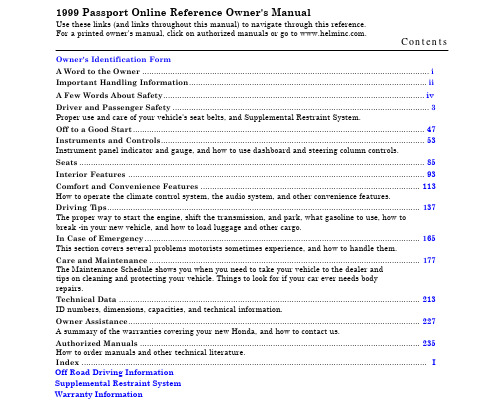
1999 Passport Online Reference Owner's ManualUse these links (and links throughout this manual) to navigate through this reference.For a printed owner's manual, click on authorized manuals or go to .Contents Owner's Identification FormA Word to the Owner (i)Important Handling Information (ii)A Few Words About Safety (iv)Driver and Passenger Safety (3)Proper use and care of your vehicle's seat belts, and Supplemental Restraint System.Off to a Good Start (47)Instruments and Controls (53)Instrument panel indicator and gauge, and how to use dashboard and steering column controls. Seats (85)Interior Features (93)Comfort and Convenience Features (113)How to operate the climate control system, the audio system, and other convenience features.Driving T ips (137)The proper way to start the engine, shift the transmission, and park, what gasoline to use, how tobreak -in your new vehicle, and how to load luggage and other cargo.In Case of Emergency (165)This section covers several problems motorists sometimes experience, and how to handle them.Care and Maintenance (177)The Maintenance Schedule shows you when you need to take your vehicle to the dealer andtips on cleaning and protecting your vehicle. Things to look for if your car ever needs bodyrepairs.Technical Data (213)ID numbers, dimensions, capacities, and technical information.Owner Assistance (227)A summary of the warranties covering your new Honda, and how to contact us.Authorized Manuals (235)How to order manuals and other technical literature. Index (I)Off Road Driving InformationSupplemental Restraint SystemWarranty Information。
Bosch VG4 AutoDome Modular 风扇风琴相机技术指导书说明书

© 2010 Bosch Security Systems, Inc.850 Greenfield Road, Lancaster PA, 17601 USA Contact Information: AMEC: (888) 289-0096 EMEA: 31 (0) 76-5721500 VG4TBC_01_25_10_VG4_Position_Accuracy.doc2/10VG4 PositionAccuracy Page 1 of 3TECHNICAL BULLETIN CCTVVG4 Position AccuracyAutoDome Modular Cameras in Extreme Vibration EnvironmentsFebruary 24, 20101.0 IssueRecent product enhancements to the hardware and firmware of the AutoDome Modular Camera System (VG4 Series) extend the use of the AutoDome to bridge and to other high vibration applications. AutoDome cameras in extreme vibration applications have been observed to have issues with:• loss of Home position • loss of position accuracy•shifts in predefined virtual and privacy masks2.0 ResolutionBosch Security Systems, Inc. has improved the AutoDome Camera unit and upgraded the VG4 firmware to better cope with extreme vibrations.The following table summarizes the dates when these fixes were included in new AutoDomes: Region Date Corrected in Production AMEC Week 5, 2010 (February 2010) EMEA Week 6, 2010 (February 2010) APR/AustraliaWeek 14, 2010 (April 2010)© 2010 Bosch Security Systems, Inc.850 Greenfield Road, Lancaster PA, 17601 USA Contact Information:AMEC: (888) 289-0096EMEA: 31 (0) 76-5721500VG4TBC_01_25_10_VG4_Position_Accuracy.doc2/10VG4 PositionAccuracyPage 2 of 3These AutoDomes contain the following fixes:•Counterweight added to the rear carriage blind (photos below) to adjust the balance to a neutral center of gravity. This improves the balance of the PTZ camera head. (Note: The magnet has notchanged; it is shown for reference only.•VG4 Service Pack Version 1.08 installed to correct the issues with position accuracy and with virtual and privacy masks. The acceleration/deceleration has been optimized to prevent degradation of the cameras home position.To apply these fixes to an AutoDome in the field, please continue to the next sections.2.1 Camera Unit ReplacementFor cameras already used in extreme vibration applications, please contact your regional Bosch Security Systems Service Center for further instructions.2.2 Firmware UpdateThis firmware upgrade may be performed in the field using VG4 Service Pack Version 1.08.1. Download the Service Pack files from the from the Bosch Security Systems Web site() to the computer that will perform the firmware update to the VG4 camera. The Service Pack is located on the Software tab of any AutoDome Modular Series product page.2. Update the firmware on the AutoDome using the files in the VG4 Service Pack Version 1.08. Refer tothe VG4 Series Firmware Update Manual for detailed instructions. This manual is also located on the Software tab of any AutoDome Modular Series product page.3. Once the firmware update is complete, issue the ON 66 Aux command. The firmware versionhighlighted in the red box below should match the number on the updated AutoDome (the number in the red box is the SCMain version):Blind© 2010 Bosch Security Systems, Inc.850 Greenfield Road, Lancaster PA, 17601 USA Contact Information:AMEC: (888) 289-0096EMEA: 31 (0) 76-5721500APR: 86 (0) 756 7633117VG4TBC_01_25_10_VG4_Position_Accuracy.doc2/10VG4 PositionAccuracyPage 3 of 3Note: The series, camera type, and IP information for your AutoDome may differ from the example.。
Dahua 4MP HD-AVS WDR IR Dome Camera 说明书

AVS-4MD4025-IR4MP HD-AVS WDR IR Dome Camera●120dB True WDR, 3DNR ●Max 4MP real-time●HD and SD dual-output ● 2.8mm fixed lens●Max. IR length 30m, Smart IR ●IP67, IK10, DC12V4 Signals over 1 Coaxial CableHD-AVS technology supports 4 signals to be transmitted over 1 coaxial cable simultaneously, i.e. video, audio*, data and power. Dual-way data transmission allows the HD-AVS camera tointeract with the AVR, such as sending control signal or triggering alarm. Moreover, HD-AVS technology supports PoC for construction flexibility.* Audio input is available for some models of HD-AVS cameras.Long Distance TransmissionHD-AVS technology guarantees real-time transmission at long distances without any loss. It supports up to 2,296’ / 700mtransmission for 4K and 4MP HD video via coaxial cable, and up to 984’ / 300m via UTP cable.SimplicityHD-AVS technology inherits the born feature of simplicity from traditional analog surveillance system, making itself a best choice for investment protection. HD-AVS system can seamlesslyupgrade the traditional analog system without replacing existing coaxial cabling. The plug and play approach enables full HD video surveillance without the hassle of configuring a network.Experience superior 4MP video, a complete set of features, and the simplicity of reusing existing coaxial infrastructure with HD-AVS. The 4MP HD-AVS camera with 120dB true WDR presents a high quality image with rich details and accurate color rendition for applications with complex lightingconditions. It offers various motorized/fixed lens models with a multi-language OSD and HD&SD dual output. Its high resolution and complete set of features makes the 4MP HD-AVS camera an ideal choice for mid to large-sizebusinesses and projects where both highly reliable surveillance and construction flexibility are needed.System OverviewFunctionsMulti-outputsThe camera supports HD-AVS and CVBS signal outputssimultaneously with two BNC connectors. Multi-outputs facilitates construction in such situations as debugging through a tester. It also offers the possibility for cooperating with multiple devices including analog matrix or monitor.Smart IRWith IR illumination, detailed images can be captured in low light or total darkness. The camera's Smart IR technology adjusts to the intensity of camera's infrared LEDs to compensate for the distance of an object. Smart IR technology prevents IR LEDS from whiting out images as they come closer to the camera. The camera's integrated infrared illumination provides high performance in extreme low-light environments up to 30m (98ft).Wide Dynamic RangeThe camera achieves vivid images, even in the most intensecontrast lighting conditions, using industry-leading wide dynamic range (WDR) technology. For applications with both bright and low lighting conditions that change quickly, true WDR (120 dB) optimizes both the bright and dark areas of a scene at the same time to provide usable video.Advanced 3DNR3DNR is noise reduction technology that detects and eliminates random noises by comparing two sequential frames. IC Realtime’s advanced 3DNR technology allows remarkable noise reduction with little impact to sharpness, especially under limited lighting conditions. 3DNR also effectively decreases the required bandwidth and helps lower storage space requirements.Large Aperture LensThe camera adopts high-end F1.5 large aperture lens. With higher amount of absorbed light, the camera presents an impressive low light performance.ProtectionThe camera's outstanding reliability is unsurpassed due to its rugged design. The camera is protected against water and dust with IP67 ranking, making it suitable for indoor or outdoor environments. Supporting ±25% input voltage tolerance, this camera suits even the most unstable power supply conditions. Its 4KV lightning rating provides protection against the camera and its structure from the effects of lightning.Technical SpecificationImage Sensor 1/3" CMOSEffective Pixels 2688(H)×1520(V), 4.1MP Scanning System ProgressiveElectronic Shutter SpeedPAL: 1/4s~1/100,000s NTSC: 1/3s~1/100,000s Minimum Illumination 0.01Lux/F1.5, 30IRE, 0Lux IR on S/N Ratio More than 65dB IR Distance Up to 30m (98ft)IR On/Off Control Auto / Manual IR LEDs12Lens Type Fixed lens / Fixed iris Mount Type Board-in Focal Length 2.8mm Max. Aperture F1.5Angle of View H: 99.7°Focus Control FixedClose Focus Distance 900mm (35.43ft)DORI DistanceLens Detect Observe Recognize Identify 2.8MM63m(208ft)25m(83ft)13m(42ft)6m(21ft)LensCameraPan/Tilt/Rotation RangePan: 0° ~ 355° Tilt: 0° ~ 65°Rotation: 0° ~ 355°Pan/Tilt/RotationResolution 4MP (2560×1440)Frame Rate 25fps@4MP, 25/30fps@1080P, 25/30fps@720P Video Output 1-channel BNC HD-AVS high definition video output & 1-channel BNC CVBS video output Day/Night Auto (ICR) / Manual OSD Menu Multi-languageBLC Mode BLC / HLC / WDR (120dB)WDR 120dB Gain Control AGC Noise Reduction 2D/3D White Balance Auto / Manual Smart IRAuto / ManualVideoCertificationsCE (EN55032, EN55024, EN50130-4) FCC (CFR 47 FCC Part 15 subpartB, ANSI C63.4-2014) UL (UL60950-1+CAN/CSA C22.2 No.60950-1)CertificationsVideo Interface 1-channel BNC HD-AVS high definition video output & 1-channel BNC CVBS video output Audio Interface N/A RS485N/A AlarmN/AInterfacePower Supply 12V DC ±25%Power ConsumptionMax 4.4W (12V DC, IR on)ElectricalOperating Conditions -30°C ~ +60°C (-22°F ~ +140°F) / Less than 90% RH *Start up should be done at above -30°C (-22°F)Storage Conditions-30°C ~ +60°C (-22°F ~ +140°F) / Less than 90% RH Ingress Protection & Vandal ResistanceIP67 & IK10EnvironmentalCasing AluminiumDimensions Φ109.9mm×81.0mm (Φ4.33"×3.19")Net Weight 0.33kg (0.73lb)Gross Weight0.45kg (0.99lb)ConstructionMounting Dimensions (mm/in)。
MAKcam V4用户手册说明书

MOUNTS • OPTICS • ELECTRONICS MAKcam V4 Owner’s Manualwww.mak.agTable of contents Control Elements . . . . . . . . . . . . . . . . . . . . . . 3 Warnings . . . . . . . . . . . . . . . . . . . . . . . . . . 4 Getting Started . . . . . . . . . . . . . . . . . . . . . . . 7 Mounting the MAKcam V4 on your riflescope. . . . . . 7 Charging the Battery . . . . . . . . . . . . . . . . . . . . 9 Powering Camera On and Off . . . . . . . . . . . . . . . 9 Battery Status. . . . . . . . . . . . . . . . . . . . . . . . 9 Modes. . . . . . . . . . . . . . . . . . . . . . . . . . . . 10 Default Camera Settings . . . . . . . . . . . . . . . . . . 10 Features . . . . . . . . . . . . . . . . . . . . . . . . . . . 11 Accessing the MAKcam V4. . . . . . . . . . . . . . . . . 11 Application Interface . . . . . . . . . . . . . . . . . . . . 13 Maintanance and Service . . . . . . . . . . . . . . . . . 16Control Elements765 31241Wi-Fi/HDMI Button 2Shutter Button3Power Button4Scope Mounts 5Status LED Bar6Mini HDMI Port7Battery Charging PortThe machine is designed and intended for private use. It should only be used on proper riflescope. Use for any other purpose will be deemed improper. MAK AG cannot accept any responsibility for the consequences of improper use.Before using the tool read these instructions for use thorough -ly and completely and comply with the instructions they contain. Keep these instructions for use close to the tool and pass them on to the next ing a charger other than a MAKcam V4 can damage the camera battery and could result in fire or leakage. Only use chargers marked: Output 5V 1A.Device is equipped with integrated battery. Do not attempt to replace the battery yourself. The battery in MAKcam V4 should be replaced by KILIC Feintechnik or an authorized service provider.MAKcam V4 is conformed to following directives:• Low Voltage Directives 2014 /35 /EU • EMV 2014 / 30 / EU • RoHS • REACHConformitiesWarningsBattery WarningsTo avoid danger of potentially fatal electric shock:• Do not dismantle, open or shred integrated battery.• Do not short-circuit the integrated battery.• Do not remove integrated battery.• Do not subject batteries to mechanical shock.• In the event of a battery leaking, do not allow the liquid to come in contact with the skin or eyes. If contact has been made, wash the affected area with copious amounts of water and seek medical advice.• Do not use any charger other than that specifically provided for use with the equipment.• Seek medical advice immediately if a battery has been swallowed.• Wipe the battery charging port with a clean dry cloth if they become dirty.• Do not leave a battery on prolonged charge when not in use.Observe proper precautions when handling batteries.Batteries may leak or explode if improperly handledA defective machine is not safe and could cause injury or fire. To avoid damage and any associated risk of injury or fire:• Protect the MAKcam V4 from environmental influences such as rain, frost and direct sunlight.• Do not immerse the MAKcam V4 cables or connections in water.• Do not put the MAKcam V4 or any individual parts in the dishwasher.• Switch your MAKcam V4 off at the power switch before any cleaning operation• Always wipe the MAKcam V4 with a damp cloth rather than a wet one, and protect it from prolonged exposure to water splash.• Do not drop, disassemble, open, crush, bend, deform, puncture, shred, microwave, incinerate or paint the camera.• Do not insert foreign objects into any opening on the camera, such as the USB port.• Do not dry the camera or battery with an external heat source such as a microwave oven or hair dryer.• Place the tool out of the reach of children.Do not place naked flame sources, such as lightedcandles, on or near the product.Getting StartedMounting the MAKcam V4 on your riflescope1. First install the camera to scope mount on the ocular side of the scope as in the picturePicture 1 Picture 22. Position the MAKcam V4 on the camera to scope mount so that the male lugs of the camera housing unit mate with the female lug recess in the mount and rotate clockwise until the locking lever engages and locks up.Please verify that the camera and reticle are aligned.This can be verified by using the HDMI Mode. If not,adjust the mount on the ocular until they are and thentighten the screws on the mount. For the perfect ima-ge, it is vital that the alignment of camera and reticle isproperly aligned.3. If you want to dismount the MAKcam V4 unit from the scope you simply operate the locking lever and rotate counter clockwise. The camera to scope mount remains with the rifle scope permanently and is ready to have the camera unit attac -hed without hindering it’s normal rifle scope functions.Please pay attention that when mounting/installing the camera unit on the rifle scope that the picture quality is clear and clean. When this is not the case you will have to adjust the camera to scope mount slightly forward or aft until clear and clean images are seen. This is best done when the camera unit is connected to the computer.Always check and be certain that the firearm is unloaded before undertaking any work upon it.To verify if the view is perfectly aligned and perpendicular;• Turn on the HDMI Mode or wifi mode • Link the MAKcam V4 to the monitor via HDMI cable (see img.2) or connect wifi and start video stream on user inter -face • Check if the device is properly alignedCharging the Battery• Charge the battery by connecting the MAKcam V4 using the included charging kit.• The MAKcam V4 power status led blinks during charging.• Once the device is completely charged, power led statusstops blinking.To Power On:Press the Power button until the green LED turns on.When the yellow led blinks, MAKcam V4 is ready to use.To Power Off:Press the Power button until the green LED turns off Powering Camera On and OffBattery Status• Power led blinks on the status led bar if the battery drops below 30%.• If the battery reaches 0% while recording, the camera saves the file and powers off.ModesDefault settings for the MAKcam V4 is as following:• Video/Photo resolution: 720p, 25fps • HDMI mode resolution: 1080p, 40fps • Wi-Fi Credentials: SSID: MAKcamV4 Password: makcam2021 Default Camera SettingsModeStart Stop Photo ModePress the shutter button. Red led blinks once.-Video Mode Press and hold the shutter button for two seconds. Red led blink continiously.Press the shutter button. Red led stops blinking.Wi-Fi Stream Mode Press and hold the Wi-Fi/HDMI button for two se -conds. Blue led blinks con -tiniouslyPress the Wi-Fi/HDMI button. Blue led stops blinking. HDMI ModePress the Wi-Fi/HDMI but -ton. Blue led turns on.Press the Wi-Fi/HDMI button. Blue led turns off.To reset the Wi-Fi settings;Wi-Fi button must be pressed for 10+ seconds. This will reset the wifi ssid and password to the default settings.MOUNTS • OPTICS • ELECTRONICS FeaturesThe device is compatible with the MAKcam V4 App, which is available on Windows, Apple and Android devices.The MAKcam V4 App allows you to control the action camera, retrieve media and provides a live stream through Wi-Fi. Accessing the MAKcam V4SmartphonesIn order to download the App for the smartphone scan the appropriate QR Code belowwww.mak.ag/products/electronics/makcam/makcam-v4/ DesktopDesktop app for the MAKcam V4 can be downloaded through thewww.mak.ag/products/electronics/makcam/makcam-v4/Web BrowserAlternatively, any type of web browser can be used to access the camera.1. Push on the Wi-Fi button for three seconds to activate the wireless mode.2. Please make sure that the blue blink appears on the status led bar indicating that the Wi-Fi mode is active.3. In your computer, smart phone or tablet’s Wi-Fi settings, connect to the corresponding network that matches the came-ra’s screen. The network name is “MAKcamV4” by default.4. When prompted, enter the password “makcam2021” which should also match your camera’s screen.5. Open the MAKCam V4 app on your corresponding device. Once open, press connect where it shows the camera icon. Once connected you can change modes and settings from your device as well as preview live stream, media, and download your photos and videos.Optionally, open your computer’s preferred web browser and type in the following address: 192.168.5.1Application InterfaceGeneral overview regarding the application interface is shown below.123456 MAKcam V4 Desktop Application1Start / Pause Stream: It is used to pause the active stream or start the live preview.2Record Video: Pressing on this button is used to start the videorecord and converts the button background to the red colour indica-ting that the device is recording video3Take a Photo: This button is used to capture a photo.4Media Folder: Access to the media folder.5Settings: Access to the settings panel.6Live Stream: In order to make the live preview full screen, pleasepress on the stream.Application InterfaceGeneral overview regarding the application interface is shown below.MAKcam V4 Desktop App – MediaApplication InterfaceMAKcam V4 for SmartphoneMAKcam V4 - Settings PanelMaintanance and Service• Only qualified and authorized personnel should make repairs to this product.• MAKcam V4 is easy to maintain and does not require special maintenance during normal operation.• Make sure to clean camera regularly with an optical towel.• Please do not make any change on MAKcam V4 by yourself.Warranty and DisclaimersThe guarantee period is 5 years on mechanical and 2 years on optical or electronic components. If device becomes defe-ct within this period, please inform our service department. Damage due to incorrect use and interventions are excluded from the guarantee.CONTACT OUR CUSTOMER SERVICE DEPARTMENT:Tel.: +49 9723 93805-0Fax: +49 9723 93805-129CONTACT OUR CUSTOMER SERVICE DEPARTMENT VIATHE INTERNET:************https://www.mak.agCustomer Satisfaction Surveyrepresents the need of separate disposal of the product and accessories. They should not be dumped with regular household waste but must be returned to a recycling collection point for electrical devices. Recycling helps reduce the consumption of raw materials.-mation regarding this matter, contact our company or nearest recycling center.Warranty FormIf you experience any problems with our products return it with this document enclose an explanation of the problemItem Number:______________________________________________Product name:_____________________________________________Purchased Date:____________________________________________Dealer/Distributor:__________________________________________Your Name:________________________________________________Your Adress:_______________________________________________City:______________________________________________________Phone:____________________________________________________E-mail:____________________________________________________Brief Remark/Description of problem: ________________________________________________________________________________________________________________________________________________________________________________________________________MOUNTS • OPTICS • ELECTRONICS。
Perforce 2013.1 P4V入门说明书

Perforce 2013.1 P4V入门2013年4月基本概念This manual copyright 2005-2013 Perforce Software.All rights reserved.Perforce software and documentation is available from . You may download and use Perforce programs,but you may not sell or redistribute them. You may download, print, copy, edit, and redistribute the documentation, but you may notsell it, or sell any documentation derived from it. You may not modify or attempt to reverse engineer the programs.This product is subject to U.S. export control laws and regulations including, but not limited to, the U.S. Export Administration Regulations, the International Traffic in Arms Regulation requirements, and all applicable end-use, end-user and destinationrestrictions. Licensee shall not permit, directly or indirectly, use of any Perforce technology in or by any U.S. embargoed country or otherwise in violation of any U.S. export control laws and regulations.Perforce programs and documents are available from our Web site as is. No warranty or support is provided.Warranties and support, along with higher capacity servers, are sold by Perforce Software.Perforce Software assumes no responsibility or liability for any errors or inaccuracies that may appear in this book.By downloading and using our programs and documents you agree to these terms.Perforce and Inter-File Branching are trademarks of Perforce Software. Perforce software includes software developed by theUniversity of California, Berkeley and its contributors. This product includes software developed by the OpenSSL Project for use inthe OpenSSL Toolkit (/).All other brands or product names are trademarks or registered trademarks of their respective companies or organizations.本手册的中文版本由上海龙智数码科技股份有限公司()翻译本手册版权归Perforce公司( Perforce Software)所有保留一切权利.Perforce软件和文档可以从上获得。
弗兰克e 全配件盒 用户手册
Ras Al Khaimah Phone +971 7 203 4700
United Kingdom Franke UK Ltd. Manchester M22 5WB Phone +44 161 436 6280
USA Franke Kitchen Systems LLC Smyrna, TN 37167
France Franke France S.A.S. 60230 Chambly Phone +33 130 289 400
Franke Futurum AB
Morocco
930 47 Byske
Franke Kitchen System SARL Phone +46 912 405 00
21 000 Casablanca
Egypt S.A.E. 6th of October City Hotline 16828
(PR Kitchen Systems) Auckland 2150 Phone +64 9 964 0400
08174 Sant Cugat del Vallès Phone +34 93 565 3535
Accessory set
All In - set 1 All In - set 2 All In - set 3 All In - set 4 All In - set 5
x
x
x
x
x
x
x
x
x
x
x
x
x
x
x
x
x
x
x
x
x
x
–2–
1
min. 340 - max. 540 mm min. 340 mm
Switchtec PFX PCIe Gen4 扇形交换器家族说明书

SummaryThe Switchtec PFX PCIe Gen4 Fanout Switch Family comprises high-reliability switchessupporting up to 100 lanes, 52 ports, 26 virtual switch partitions, 48 non-transparent bridges (NTBs), hot- and surprise-plug controllers for each port, advanced error containment and comprehensive diagnostics and debug capabilities.Typical applications for the PFX include data center equipment, defense and industrial servers, workstations, test equipment, video production and broadcasting equipment, cellular infra-structure, access networks, metro networks and core networking.Switchtec TM PFX PCIe ® Gen4 Fanout Switch FamilyPM40100, PM40084, PM40068, PM40052, PM40036, PM40028FeaturesHigh-Performance Non-Blocking Gen4 Switches• 100-lane, 84-lane, 68-lane, 52-lane, 36-lane and 28-lane variants• Ports bifurcate from to x11 /x2/x4/x8/x16 lanes • Up to 48 NTBs assignable to any port• Logical non-transparent (NT) interconnect allows for larger topologies (up to 256 masters)• Supports 1+1 and N+1 failover mechanisms• NT address translation using direct windows and multiple sub-windows per BAR• Supports multicast groups per portDMA Controller• High-performance, ultra-low latency cut-through DMA engine • Up to 64 DMA channelsError Containment• Advanced Error Reporting (AER) on all ports• Downstream Port Containment (DPC) on all downstream ports • Poisoned TLP blocking•Completion Timeout Synthesis (CTS) to prevent an error state in an upstream host due to incomplete non-posted transactions• Hot- and surprise-plug controllers per port• GPIOs configurable for different cable/connector standardsPCIe Interfaces• Passive, managed and optical cables• SFF-8644, SFF-8643, SFF-8639, OCuLink and other connectors• SHPC-enabled slot and edge connectorsDiagnostics and Debug• Transaction Layer Packet (TLP) generator for testing and debugging of links and error handling • Real-time eye capture• External loopback capability• Errors, statistics, performance and TLP latency countersHighlights• High-reliability PCIe: robust error containment, hot- and surprise-plug controllers per port, end-to-end data integrity protection, ECC protection on RAMs, high-quality, low-power SERDES• Comprehensive diagnostics and debugging: PCIe genera-tor and analyzer, per-port performance and error counters, multiple loopback modes and real-time eye capture• Significant power, cost and board space savings with sup -port for:• Up to 52 ports, 48 NTBs, and 26 virtual switch partitions • Flexible x11, x2, x4, x8, and x16 port bifurcation with no restrictions on configuring ports as either upstream or downstream, or on mapping ports to NTBs• Secure system solution with boot image authentication and remote attestationSwitchtec �PFX Gen4PCIe ® F anoutSwitch1x1 natively on four lanesThe Microchip name and logo, the Microchip logo and Switchtec are registered trademarks of Microchip Technology Incorporated in the U.S.A. and other countries. All other trademarks mentioned herein are property of their respective companies.© 2018, Microchip Technology Incorporated. All Rights Reserved. 11/18 DS00002866APeripheral I/O Interfaces• Up to 11 Two-Wire Interfaces (TWIs) with SMBus support • Up to 4 SFF-8485-compliant SGPIO ports • Up to 103 parallel GPIO pins• 10/100 Ethernet MAC port (MII/RMII) (PFX 96x/80x/64xG4)• Up to 4 UARTs•JTAG and EJTAG interfaceHigh-Speed I/O• PCIe Gen4 16 GT/s• Supports PCIe-compliant link training and manual PHY configuration• Manual PHY configuration for opticalPower Management• Active State Power Management (ASPM)• Software-controlled power managementChipLink Diagnostic Tools• Extensive debug, diagnostics, configuration and analysis tools with an intuitive GUI• Access to configuration data, management capabilities and signal integrity analysis tools (such as real-time eye capture)• Connects to device over in-band PCIe or sideband signals (UART, TWI and EJTAG)Evaluation KitThe PM42100-KIT Switchtec Gen4 PCIe Switch Evaluation Kit is a device evaluation environment that supports multiple interfaces.Example Application。
Twin City Fan Companies 140A-240A BCFS 模型风扇说明书

Model BCFS 140A through 240A©2006 – 2018 Twin City Fan Companies, Ltd.Receiving, Inspection & UnpackingWhen the equipment is received all items should be carefully checked against the bill of lading to be sure all crates and cartons have been received. Before accepting delivery, carefully inspect each carton or crate for visible shipping damage. If any damage is noticed, the carrier should make the proper notation on the delivery receipt acknowledging the damage. Make notations of all damage on all copies of the bill of lading and have all copies countersigned by the delivering carrier. The carrier should also fill out a Carrier Inspection Report. The factory Traffic Department should then be contacted. File claim for damage with the carrier. Physical damage to the unit after acceptance is not the responsibility of Twin City Fan Companies, Ltd.Unpack each carton or crate and verify that all required parts and proper quantities of each item have been received. Refer to drawings for part descriptions. Report shortages or missing items to your local representative to arrange for replacement parts.Due to availability of carriers and truck space, it is not possible to guarantee that all items will be shipped together. Verification of shipments must be limited to only those items on the bill of lading.The unit nameplate must be checked to make sure the voltage agrees with the power supply available.2Twin City Installation and Maintenance Manual IM-4300Check, Test and Start Procedure 1. Check to verify that the wheel is free to rotate.2. Verify that supply voltage on the line side of disconnect agrees with voltage on unit identification plate and is within the utilization voltage range as indicated in Table 1.3. On three-phase units check and calculate phase unbalance as follows: % Voltage Unbalance = 100 x max. voltage deviation from avg. voltage ÷ avg. voltage Example: Determine the percent voltage unbalance given voltages of 220, 216 and 213. How To Use The Formula:a. Avg. Voltage = 220 + 216 + 213 = 649 ÷ 3 = 216b. Max. Voltage Deviation From Avg. Voltage =220 – 216 = 4c. % Voltage Unbalance = 100 x (4 ÷ 216) = 1.8% Voltage unbalance should not exceed 2%.4. Apply power to unit and check rotation of wheel with the directional arrow on the unit.5. Electrical Input Check: Perform check of fan ampere draw and verify that motor nameplate amps are not exceeded. Take account of the service factor range if motor is nameplated above a 1.0 service factor.6. Fan RPM Check: Fan RPM should be checked and verified with a tachometer. Refer to Table 2for maximum fan RPM values.InstallationThe installation of this equipment shall be in accordance with the regulations of authorities having jurisdiction and with all applicable codes.This equipment is to be installed by an experienced installation company and fully trained personnel.The mechanical installation of the exhaust ventilator consists of making final connections between the unit, building services, and duct connections.1. Before setting unit on curb (if damper is to be used), make sure that the damper is installed correctly and that it is operative. See diagram, page 4.2. Position unit on roof curb so that the wiring can be run through one of the knockouts provided. Wiring to the unit may be run through knockouts provided in the curb cap or the side of the unit. Provide enough slack in the wiring to the unit to allowlifting, and removal for cleaning, and inspection.3. Connect supply leads to the disconnect switch.4. Check line voltage with the motor nameplate and the attached instruction cards.5. Determine if wheel is free to rotate and has not been subject to misalignment in shipping or installation.6. Apply power and check rotation of wheel with directional label in motor compartment.7. Lag bolt the unit to the roof curb using a minimum of four bolts, one at each corner. Replace unit top panel and fasten all latches securely.3Twin City Installation and Maintenance Manual IM-4300FILTERS: To gain access to filters, unlatch top panel and slide top back approximately 2 inches. Lift filters out from top. Filters may be cleaned with soap and water or replaced. Filters should be cleaned regularly, as dirty filters will cause performance to be reduced. Frequency of cleaning depends upon the local environment and frequency of use of the fan.1. The motors in these units are equipped with prelubricated ball bearings which are considered to be permanently lubricated.2. Fan shaft pillow block bearings are equipped with grease gun fittings. These bearings are factory lubricated and, with normal operation, will need no lubrication for 3 to 6 months.3. For pillow block bearings, use a low pressure grease gun with Shell Gadus S2 V100 2 grease or equivalent. Only a few strokes of the gun are required. Excess grease will be forced out through the bearing pressure relief holes. Use of a high pressure gun, however, is liable to blow the bearing seals.4. Belt tension is adjusted at the factory. It should be readjusted after a break-in period of 24 hours of actual operation.5. To adjust belt tension, loosen the hex head screw in the tab of the motor plate. Snug belts by pulling on the motor until the belt is tight. Tension is correct if the belt can be twisted from 1⁄4 to 1⁄2 turn with moderate pressure at a point midway between sheaves.MaintenanceTable 1. Utilization Voltage Ranges6. Belt condition and tension should be checked every 3 to 6 months depending on service. If belt tension is too tight, there is a possibility of overloading the motor as well as causing undue belt wear. If the belt tension is too slack, then the wheel will fall off in RPM, air delivery will decrease and the belts will wear quite rapidly.7. If the air handled by the unit is dust or grease laden, a regular inspection and cleaning of the backdraft damper and the wheel will ensure smooth, efficient operation.CHECK: Belt tension is adjusted at the factory, but it should be readjusted after a break-in period of approximately 24 hours of actual operation.4Twin City Installation and Maintenance Manual IM-4300Figure 2. Opening Location of Duct Adapter AccessoryFigure 1. Typical Installation*For a standard gravity (spring return) damper, recess the damper a minimum of 2" inside the duct in order to clear the fan outlet. For an optional motorized damper, the damper must be recessed 12" to allow for clearance between the actuator and fan outlet.Figure 3. Location of Fan Outlet5Twin City Installation and Maintenance Manual IM-4300Motor InstallationTo prevent damage during shipment, the motor of this unit has been installed at the factory, tested, then removed and shipped separately. Please follow the instructions below to reinstall the motor.1. Fasten the motor plate to the bearing plate by inserting the hinge pin in the holes and then putting a hitch pin in the hole of the hinge pin. See Figure 4.2. Install the belts on the sheaves, apply tension and tighten the bolt at the top of the motor plate or the nut on the jacking bolt to maintain tension. The ideal belt tension is to be enough so that the belt does not slip under peak load. Do not over-tighten the belt as it will severely reduce the life of the bearings.3. Check the sheave alignment as shown in Figure 5 below and align sheaves with a straightedge if necessary. Be sure the belt tension is rechecked if the sheave alignment is changed.Figure 4. Motor Plate AssemblyFigure 5. Sheave AlignmentSeller warrants to the original purchaser that the goods sold hereunder shall be free from defects in workmanship and material under normal use and service (except in those cases where the materials are supplied by the buyer) for a period of one year from the date of original installation or eighteen (18) months from the date of shipment, whichever occurs first. The liability of seller under this warranty is limited to replacing, repairing, or issuing credit (at cost, F.O.B. factory and at seller’s discretion) for any part or parts which are returned by buyer during such period provided that:a. seller is notified in writing within ten (10) daysfollowing discovery of such defects by buyer, or within ten (10) days after such defects should reasonably have been discovered, whichever is less;b. the defective unit is returned to seller, transportationcharges prepaid by buyer.c. payment in full has been received by seller for saidproducts; andd. seller’s examination of such unit shall disclose to itssatisfaction that such defects have not been caused by misuse, neglect, improper installation, repair, alteration, act of God, or accident.No warranty made hereunder shall extend to any seller product whose serial number is altered, effaced or removed. Seller makes no warranty, express or implied, with respect to motors, switches, controls, or other components of seller’s product, where such components are warranted separately by their respective manufacturers. THIS WARRANTY IS EXPRESSLY IN LIEU OF ALL OTHER WARRANTIES, EXPRESS OR IMPLIED, WHETHER STATUTORY OR OTHERWISE, INCLUDING ANY IMPLIED WARRANTY OF MERCHANTABILITY OR FITNESS FOR A PARTICULAR PURPOSE. In no event shall seller be liable to buyer for indirect, incidental collateral, or consequential damages of any kind. (BUYER’S FAILURE TO PAY THE FULL AMOUNT DUE WITHIN SIXTY (60) DAYS OF DATE OF INVOICE SHALL OPERATE TO RELEASE SELLER FROM ANY AND ALL LIABILITY OR OBLIGATION ARISING PURSUANT TO ANY WARRANTY, EXPRESS OR IMPLIED, WHETHER STATUTORY OR OTHERWISE, INCLUDING ANY IMPLIED WARRANTY OR MERCHANTABILITY OR FITNESS FOR A PARTICULAR PURPOSE, MADE IN CONNECTION WITH ANY CONTRACT FORMED HEREUNDER. BUYER AGREES THAT SUCH FAILURE TO PAY SHALL CONSTITUTE A VOLUNTARY WAIVER OF ANY AND ALL SUCH WARRANTIES ARISING PURSUANT TO SUCH CONTACT.)Limitation of Warranties and ClaimsTWIN CITY FAN & BLOWER | 5959 Trenton Lane N | Minneapolis, MN 55442 | Phone: 763-551-7600 | Fax: 763-551-7601。
FUJITSU Storage ETERNUS DX S4C 商品介绍说明书

ETERNUS DX - Business-centric StorageFUJITSU Storage ETERNUS DX S4C is the perfect hybrid storage for SMB, something every business can afford, with integrated and powerful features for business growth, efficiency and continuity. Latest capacity and performance optimization capabilities contribute to comprehensive business efficiency.Outstanding data-safe technologies and all-inclusive encryption guarantee uncompromised business continuityETERNUS DX200 S4CThe scalable and unified Fujitsu Storage ETERNUS DX200 S4C delivers enterprise-classfunctionality to small and medium-sizedcompanies and subsidiaries with an excellentprice/performance ratio. It is the perfect solution when consolidating data for server virtualization, e-mail, databases and business applications as well as centralized file services.Simple, intuitive system management, highly flexible connectivity and the option of field upgrades to higher system classes significantly reduce operational and migration costs. The ETERNUS DX family architecture lets customers benefit from software options, such as thinprovisioning, automatic storage tiering, transparent failover and quality of service management even as early as the entry-level class. This all contributes tobetter business support.Data SheetFUJITSU Storage ETERNUS DX200 S4C Disk System(For Custom Pro jects - please contact FUJITSU Poland) The all-in-one storage system for SMBs or subsidiaries:Features & BenefitsTechnical detailsGeneral system information2.5-inch Controller Enclosure3.5-inch Controller EnclosureNo. of controllers1/2No. of host interfaces2/4/8 ports [FC, iSCSI, SAS], 8/16 ports [Ethernet(1Gbit/s)], 4/8 ports [Ethernet(10Gbit/s)] Maximum System Memory64GBExtreme Cache Pool up to1600 GBMaximum Disk Drives264Max. no. of drive enclosures10Note10 with 2.5” or 3.5” DE, 4 with HD-DE or mixture of DEs up to Max no. DrivesSupported RAID levels0, 1, 1+0, 5, 5+0, 6Host Interfaces Fibre Channel (32Gbit/s, 16Gbit/s, 8Gbit/s)iSCSI (10 Gbit/s [10GBase-SR, 10GBase-CR, 10GBase-T], 1 Gbit/s)Ethernet (10 Gbit/s, 1 Gbit/s)SAS (12Gbit/s)Mixed host interfaces YesMax. no. of hosts1,024Supported NAS protocols CIFS (SMB 2.0), CIFS (SMB 3.0), NFSv2, NFSv3, NFSv4Maximum Storage Capacity HDD3,168 TBMaximum Storage Capacity SSD4,055 TBDrive Type 2.5-inch, SAS, 15,000 rpm (900 GB / 600 GB / 300 GB)2.5-inch, SAS, 10,000 rpm (2.4 TB/ 1.8 TB / 1.2 TB / 900 GB / 600 GB / 300 GB)2.5-inch, SAS (self-encrypting), 10,000rpm (2.4 TB/ 1.2TB)2.5-inch, Nearline SAS, 7,200 rpm (2 TB / 1 TB)2.5-inch, SSD (15.36TB / 7.68TB /3.84 TB / 1.92 TB / 960GB / 400 GB)2.5-inch, SSD (self-encrypting) (3.84 TB/1.92 TB/ 400 GB)3.5-inch, Nearline SAS, 7,200 rpm (12 TB/ 10 TB / 8 TB / 6 TB / 4 TB / 2 TB)3.5-inch, Nearline SAS (self-encrypting), 7,200 rpm (12 TB/ 8 TB/ 4 TB)3.5-inch, SSD (3.84TB / 1.92TB / 960GB / 400GB)3.5-inch, SSD (self-encrypting) (3.84 TB/1.92 TB/ 400 GB)HDDE, SAS, 10,000 rpm (1.2 TB)HDDE, Nearline SAS, 7,200 rpm (12 TB / 10 TB / 8 TB / 6 TB / 4 TB / 2 TB)HDDE, SSD (3.84TB / 1.92TB)HDDE, Nearline SAS(self-encrypting), 7,200 rpm (12TB / 8 TB / 4TB)Note 2.5-inch drives are available only for 2.5-inch drive enclosures and 3.5-inch drives are available only for 3.5-inch driveenclosures.2.5-inch 2TB,3.5-inch 6TB/8TB/10TB Nearline SAS and 1.8TB SAS drives are Advanced Format drives.400 GB SED-SSD is not available in EMEIA regionMixed 2.5 inch/ 3.5 inch drive enclosures YesDrive interface Serial Attached SCSI (12 Gbit/s)Back-end disk connectivity 1 pair of four-lane x 12 Gbit/s Serial Attached SCSI buses (SAS 3.0 wide)Max. no. of LUNs8,192Max. LUN capacity128 TBNo. of snapshots - max.2,048Max. no. of copy generations512Eco-mode YesDeduplication for blockCompression for blockPerformance managementAutomated Storage Tiering YesQuality of Service YesPerformance managementAutomated QoS YesWide striping YesNote Automation options can be activated via ETERNUS SF SoftwareContinuity managementStorage Cluster YesRemote Copy functionality Synchronous and asynchronousNote Options can be activated via ETERNUS SF SoftwareInformation security managementData confidentiality Self-Encrypting Disk, Controller based Encryption, HTTPS (SSL), One Time Password, RADIUS, SSH Data integrity Cache Protection, Data Block Guard, Disk Drive PatrolAvailability managementFast Recovery YesNon-disruptive maintenance Dedicated Hot Spare, Global Hot SpareNon-disruptive firmware upgrade YesRedundancy RAID Controller (in 2-controller configuration), Fan, Power supplyHot part replacement YesCapacity managementThin Provisioning YesRAID migration YesLUN online expansion w/o interruption YesReporting function YesHot part expansion YesManagementInterfaces Ethernet (1000 Base-T / 100 Base-TX / 10 Base-T)Supported protocols SNMP (version1, 2C, 3), SMI-S 1.6Administration Web-based graphical user interface, CLI (Command Line Interface), ETERNUS SFRemote Support Event notification (E-mail / SNMP / Syslog), Remote maintenanceSupported OS for ETERNUS SF ExpressOperation Management Server Microsoft® Windows Server® 2016Microsoft Windows Server 2012, 2012 R2Microsoft Windows Server 2008, 2008 R2Solaris® 11 (11/11 or later)Solaris® 10Red Hat® Enterprise Linux® 7Red Hat® Enterprise Linux® 6Red Hat® Enterprise Linux® 5VMware® vSphere® 6.0, 6.5VMware® vSphere® 5/ 5.1/ 5.5Microsoft Windows Server 2016 Hyper-VMicrosoft Windows Server 2012 Hyper-V, 2012 R2 Hyper-VMicrosoft Windows Server 2008 Hyper-V, 2008 R2 Hyper-VHyper-V 2.0Operation Management Client Internet Explorer® 9, 10, 11FireFox® ESR 17, 24, 31, 38, 45, 52Microsoft Edge® 25Chrome® 60Chrome® 47, 50 (Android®)Safari 8, 9 (iOS)Supported configurations All major host operating systems, servers and business applicationsDetailed support matrix:/global/support/products/computing/storage/disk/supported-configrationsInstallation specification19” rackmount YesService Area Front: 850 mm (33.5 inch) or moreRear: 850 mm (33.5 inch) or more Power voltage AC 100 - 120 V / AC 200 - 240 V Power frequency50 / 60 HzPower supply efficiency92 % (80 PLUS gold) Maximum Power Consumption AC 100 - 120 V: 6,720 W (6,850 VA) Maximum Power Consumption AC 200 - 240 V: 6,720 W (6,850 VA) Power phase Single2.5-inch Controller Enclosure3.5-inch ControllerEnclosure2.5-inch DriveEnclosure3.5-inch DriveEnclosureHigh-Density DriveEnclosureDimensions (W x D x H)482 x 645 x 88 mm19 x 25.4 x 3.5 inch2 U 482 x 670 x 88 mm19 x 26.4 x 3.5 inch2 U482 x 540 x 88 mm19 x 21.3 x 3.5 inch2 U482 x 560 x 88 mm19 x 22 x 3.5 inch2 U482 x 980 x 176 mm19 x 38.6 x 6.9 inch4 UWeight35 kg (77 lb)35 kg (77 lb)35 kg (77 lb)35 kg (77 lb)100 kg (220 lb) Maximum Power Consumption(AC 100 - 120 V)850W (860VA)780W (790VA)430W (440VA)340W (350VA)1300W (1320VA)Maximum Power Consumption(AC 200 - 240 V)850W (860VA)780W (790VA)430W (440VA)340W (350VA)1300W (1320VA)EnvironmentMaximum Heat Generation AC 100 - 120 V: 24,800: kJ/hAC 200 - 240 V: 24,800: kJ/hTemperature (operating)10 - 40 °CTemperature (not operating)0 - 50 °CHumidity (operating)20 - 80 % (relative humidity, non-condensing)Humidity (not operating)8 - 80 % (relative humidity, non-condensing)Altitude3,000 m (10,000 ft.)Sound pressure (LpAm)49dB(A)Sound power (LWAd; 1B = 10dB) 6.7BNoise notes Measured with single enclosure according to ISO 7779 and declared according to ISO 9296Operating environment Site Planning GuideOperating environment link /dl.aspx?id=5d99bbf7-7118-4069-99e2-ff6551df9831ComplianceProduct safety UL 60950-1, CSA 60950-1, EN 60950-1, IEC 60950-1Electromagnetic Compatibility CNS 13438, FCC Part-15 Subpart B Class A, ICES 003 Class A, EN55032, VCCI Class A, AS/NZS CISPR 32 class A Electromagnetic Immunity EN 55024CE certification2014/30/EU, 2014/35/EU, 2011/65/EUApprovals CB, CE, C-Tick, FCC, EAC, GS, VCCIEnvironmental compliance RoHS compliant, WEEE compliantCompliance notes There is general compliance with the safety requirements of all European countries and North America. Nationalapprovals required in order to satisfy statutory regulations or for other reasons can be applied for on request. Compliance link https:///sites/certificatesWarrantyWarranty period 3 yearsWarranty type Onsite warrantyWarranty Terms & Conditions /supportProduct Related Services - the perfect extensionSupport Pack Options X - Globally available in major business areas:9x5, Next Business Day Onsite Response Time9x5, 4h Onsite Response Time (depending on country)24x7, 4h Onsite Response Time (depending on country)WarrantyRecommended Service X - 24x7, Onsite Response Time: 4h Service Lifecycle 5 years after end of product life Service Weblink /supportContactFUJITSU LIMITEDWebsite: /eternus 2018-05-11 WW-ENFujitsu Green Policy Innovation is ourworldwide project for reducing burdens on the environment.Using our global know-how, we aim to contribute to the creation of a sustainable environment for future generations through IT.Please find further information at http://www./global/about/environmentdelivery subject to availability. Any liability that the data and illustrations are complete, actual or correct is excluded. Designations may be trademarks and/or copyrights of the respective manufacturer, the use of which by third parties for their own purposes may infringe the rights of such owner.。
Monoprice 4K HDR Switch with IR - 4x1 产品说明书

2Product Overview 4 Features 4 Package Contents 4 Device Layout 5 Front 5 Back 6 Installation 7 Connections 7 IR Receiver Connections 8 IR Controller Connections 8 RS-232 Control Connections 9 Selecting a Switch Input 9 Front Panel 9 IR Control 10 RS-232 Control10 Specifications11 Limited Warranty 11 Support 113Thank you for purchasing a Binary product. For proper installation and optimum performance, please read the instructions in this manual.The B-260-SWTCH-4x1 Switch features HDMI 2.0 and HDCP 2.2 compatibility and supports resolutions up to 4K @ 60Hz 4:4:4 8 bit, enabling four Ultra HD sources to be switched to one Ultra HD or non-Ultra HD display. The switch is controllable by a front panel button, IR remote**, and/or RS-232.• 4-to-1 HDMI switch• HDMI 2.0 with 4K @ 60 4:4:4 8 bit and HDCP 2.2 compliant• Supports manual switching• Supports various control options• Compact size and easy to install• 1 x B-260-SWTCH-4x1 switch• 1 x 12V DC Power adapter• 1 x Switch IR Remote (requires IR receiver, sold separately)• 1 x Phoenix Male connector (3.5 mm, 3 Pins)• 2 x Mounting ears (withs crews)• 2 x Drywall screws• 4 x Rubber feet• 1 x Installation guide**IR control requires connection to an external control system via an IR extension cable or an external IR receiver, which are sold separately.45FrontA. Power LEDOn: Power on Off: Power off B. HDMI IN 1-4 LEDOn: The HDMI IN source is selected and active.Off: The HDMI source is not selected or active.C. HDMI OUT LEDOn: An HDMI display is connected to the switch.Off: No HDMI display is not connected to the switch.D. SWITCH buttonPress to cycle through the active sources. Inactive sources will not be selectable.C DAB6BackA. +12V DCConnect the provided 12V DC power supply’s cord and tighten it in place.B. HDMI IN (1-4)Connect to the output of HDMI source(s) to the input(s) you require.C. HDMI OUTConnect to the input of an HDMI display or other similar device.D. IR Receiver PWR• ON position: IR receiver port supplies 12V power.The unit can be controlled through an IR receiver (sold separately) in the ON position.• OFF position: IR receiver port does not supply 12V power.The unit can be controlled with a standard mono cable from a control system in the OFF position.E. IR EXT.IR extension port. Connect an IR extension cable, control cable, or external IR receiver (not included) .When connecting to an unpowered IR receiver or a control device, ensure that the IR receiver power switch is in the OFF position.When connecting to a powered IR receiver, ensure that the IR Receiver Power Switch is in the ON position.F. RS-232Connect to an RS-232 control deviceCB7The B-260-SWTCH-4x1 can be placed on a solid and stable surface, installed in an equipment rack, or mounted to a wall or distribution box.When installed on a rack shelf, wall, or distribution box, we strongly recommend that the included mounting ears be used to secure the device.When installing on a solid surface, the use of the mounting ears is optional.Caution: Disconnect the power from all devices in the system before making connections. Failure to do so may damage a device1 Connect the HDMI sources (such as PC, Blu-ray player, Apple TV, 4K media player) to HDMI IN 1-4. Ensure you are using a high-quality HDMI cable capable of supplying the desired maximum resolution.2 Connect the HDMI display device (such as a TV, projector) to HDMI OUT Ensure you are using a high-quality HDMI cable capable of supplying the desired maximum resolution.3 Connect any additional control options. Refer to the IR Controller Connections or RS-232 Control Connections diagram for more details.4 Connect the provided 12V DC power adapter.5Power on all connected devicesSource to HDMI INHDMI OUT to display8IR Receiver ConnectionsT o control the switch with an IR receiver, set IR Receiver PWR to ON and connect an IR receiver (sold separately) to the IR EXT port.IR Controller ConnectionsT o control the switch with an IR controller, set IR Receiver PWR to OFF and connect the IR controller (sold separately) to the IR EXT port.Set switch for IR Receiver PWR to ONIR receiver(sold separately)IR remoteSet switch for IR Receiver PWR to OFFIR controller (sold separately)RS-232 Control ConnectionsT o control the switch using RS-232, follow the below wiring diagram.SELECTING A SWITCH INPUTFront Panel1 Press the SWITCHbutton, on the front panel, to cycle through inputs.TX RX GRS-232device pins9IR ControlThe switch can be controlled via IR using the provided IR remote or using IR via a controlsystem. In order to use the included IR remote, an IR receiver must be purchased separately.RS-232 ControlConfiguration for control system serial ports can vary. Refer to the documentation for thesystem in use for proper connection and configuration. Below are the parameters for RS-232 controlImportant:Devices must be connected to the inputs and outputs of the switch for RS-232commands to executeYou can use <CR> or <LF> to end a command All commands must end with a carriage return ora line feed10Find details of the product’s Limited Warranty and other safety, patent, and legal resources at /legal or request a paper copy from Customer Service at 866.424.4489For chat and telephone, visit /s/contactsupport• Email: ***********************• Visit for discussions,instructional videos, news, and more.1112200-B-260-SWTCH-4X1-BCopyright ©2021, Snap One, LLC. All rights reserved. Snap One and its respective logos are registered trademarks or trademarks of Snap One, LLC (formerly known as Wirepath Home Systems, LLC), in the United States and/or other countries. 4Store, 4Sight, Control4, Control4 My Home, SnapAV, Araknis Networks, BakPak, Binary, Dragonfly, Episode, Luma, Mockupancy, Nearus, NEEO, Optiview, OvrC, Pakedge, Sense, Strong, Strong Evolve, Strong VersaBox, SunBriteDS, SunBriteTV, Triad, Truvision, Visualint, WattBox, Wirepath, and Wirepath ONE are also registered trademarks or trademarks of Snap One, LLC. Other names and brands may be claimed as the property of their respective owners. Snap One makes no claim that the information contained herein covers all installation scenarios and contingencies, or product use risks. Information within this specification subject to change without notice.。
R44飞行手册

手册编号TYAL—101 R0控制编号福建天裕通用航空有限责任公司R44型直升机飞行手册公司批准:局方批准:日期:日期:目录第1章概述 (5)简介 (5)数据说明 (7)性能缩略语 (9)重量和平衡定义 (10)换算表 (11)第2章极限 (14)概述 (14)仪表彩色标志的意义 (14)空速极限 (14)附加的空速限制 (14)旋翼转速极限 (15)动力装置限制 (15)重量极限 (16)重心极限 (16)飞行和机动飞行限制 (17)飞行种类限制 (18)燃油限制 (19)仪表标识 (19)铭牌 (21)第3章紧急程序 (27)一般说明 (27)定义 (27)动力故障-一般说明 (27)最大下滑距离数据 (29)最小下降率数据 (29)空中重新起动程序 (29)水上迫降―无动力 (30)水上迫降―有动力 (30)前飞时尾桨故障 (30)悬停时尾桨故障 (31)地面起动时发动机着火 (31)空中着火 (31)飞行中电气设备起火 (32)转速表故障 (32)液压系统故障 (32)调速器故障 (33)警告灯 (33)旋翼低转速警告喇叭和警告灯 (35)第4章正常程序 (37)概述 (37)安全运行空速 (37)起动发动机以前 (43)发动机起动技巧 (44)起动发动机和试车 (44)起飞程序 (46)巡航 (47)无舱门飞行 (47)练习自转-恢复动力 (48)练习自转-并接地 (48)关闭液压系统训练 (49)进近和着陆 (49)关发动机程序 (50)抑制噪音 (50)第5章性能 (53)概述 (53)已验证过的工作温度 (53)噪音特性 (59)第6章重量和平衡 (61)概述 (61)重量和平衡记录 (61)载重说明 (63)设备清单 (66)第7章各系统说明 (70)机体 (70)旋翼系统 (70)驱动系统 (70)动力装置 (71)飞行操纵机构 (71)可拆卸的飞行操纵机构 (72)转速调速器 (73)液压系统 (73)操纵松紧调整 (74)发动机操纵机构 (74)离合器致动器 (75)燃油系统 (75)电气系统 (76)照明系统 (78)仪表板 (79)内部通话系统 (81)皮托-静压系统 (81)转速表 (81)警告灯 (82)加温和通风 (82)座椅、安全带和行李 (83)旋翼刹车 (83)一氧化碳检测器 (84)紧急定位发射器(选装) (84)第8章搬运和维护 (86)概述 (86)必需的文件 (86)必须的检查 (86)飞行员实施的预防性维护工作 (87)飞机的改装 (88)地面搬运 (88)停放 (89)发动机滑油 (89)燃油 (91)电瓶 (91)尾桨齿轮箱滑油 (92)液压油 (92)清洁直升机 (92)第9章增补版 (96)概述 (96)第10章安全措施 (98)概述 (98)安全措施 (98)第1章概述简介该《飞行员操作手册》是飞行员的操作导读。
PlayStation 4系统用户指南说明书

Parental control level 23459Approximate age of user 36101317Game rating labelsthe (PS) button.Turn on your PS4™ system by pressing the(power) button.your system. Press the (power) button for at least 7 seconds to turn off your It's possible to use up to four controllers at the same time. When you press theTo later change any settings that you skipped, select (Settings) from thePower button/Power indicatorUSB portUSB cableUSB portLAN portLAN cable modemAC IN connector HDMI OUT portconfigure settings and how to use each function. Select (Settings) > (User's Guide/Helpful Info) > (User's Guide) from the functionUse (Live from PlayStation) to view broadcasts, video clips, or screenshots shared by other players.Use (Share Play) to share the game screen with another player and play the same game together.*2Capture a screenshot of your gameplay and upload it to your social networks, or use (Messages) to sendHome screenContent areaAccess your games and other content."", "PlayStation", "" and "DUALSHOCK" are registered trademarks or trademarks of Sony "SONY", "" and "Sony Entertainment Network" are registered trademarks or trademarks of SonyUp buttonUp buttonTo charge your controller while your system is in rest mode, select an option other than [Off] in (Settings) > [Power Save Settings] > [Set Features Available in Rest Mode] > [Supply Power to USB Ports].Microphone MIC switchMono headsetStereo headset jackClipLight barUSB portUSB cableEject buttonReturn to the home screen from a gameTo return to the home screen without ending a game, press the (PS)Press and hold the (PS) button, and then select [Close Application] Press the CautionDisconnect the AC power cord from the electrical outlet only when the power indicator is off. If you disconnect it while the power indicator is lit or blinking, data might be lost or become corrupted, and you might damage your system. Be sure to read the "Turn off your system completely" section below.Select (Power) from the function screen, and then select [Enter Rest Mode]. The power indicator blinks white, and then turns orange.To exit rest mode, press the Select (Power) from the function screen, and then select [Power Options] > [Turn Off PS4]. The power indicator blinks white, and then WhiteSystem is on.OrangeSystem is in rest mode.OffSystem is off.。
DiGidot C4 V.20190227说明书

•Up to 8 universes (4096 channels) •Supports more than 50 protocols •Art-Net + DMX in & out•Art-Net/DMX recording & playback •Analog + digital triggers •Compact size•Wide voltage range (5-24 Vdc) •Easy to connect•Web interface & free App •Reliable & easy to useDiGidot C4 ExtendedIntroductionThe DiGidot C4 Extended is a multi functional LED pixel controller that converts Art-Net and DMX to SPI protocols. The output capacity goes up to 8 universes, which is 4096 channels. (depending on thelicense) The internal DHCP server, Wi-Fi and free DiGidot App grand easy access of the built in webinterface. A built in network switch allows multiple DiGidot C4 controllers to be daisy chained to create an extensive control network. The DiGidot C4 Extended o ff ers Art-Net & DMX recording, playback and triggering. Extensive triggering options such as analog and digital triggers as well as the built in calendar o ff er great flexibility for system integration. Countless extra features such as DMX in and out, Art-Net IP Address filter, Art-Net routing, HTP input signal merger, Art-Net & DMX Monitor, in-/output channel repeater, Gamma correction, adjustable fall back color, output limiters, make this product to the most powerful LED pixel controller on the market.Product imagesDATA SHEETArt. No. 20201- DiGidot C4 Extended 1 Art. No. 20202 - DiGidot C4 Extended 2 Art. No. 20203 - DiGidot C4 Extended 4Art. No. 20204 - DiGidot C4 Extended 8Pixel ControllerWiring schemes (Data) SPIDMX inDMX outSPIFor more wiring schemes, and technical information, please read the DiGidot C4 user manual.Wiring schemes (Power)DC +DC --D1D2D3D4V+PSUAC/N AC/LGND V -C4DOIMPORTANT : All Grounds, from the DiGidot C4 and all power supplies must be connected. The Ground output wires of each Data pair from the DiGidot C4 output must be equal in length as the Data wires.SpecificationsInput voltage5-24 VdcMax. Power consumption5WHousing material Self extinguishing Acrylonitril-Butadieen-Styreen(ABS)Dimensions153 x 74 x 28 mm 6.02 x 2.91 x 1.10” (L x W x H)Weight140gr | 4.93ozMounting DIN rail or surface mountedOperation Temperature (Tc)0 to 50°C | 32 to 122°FAmbient Temperature (Ta)40°C | 104°FStorage temperature-20 to 50°C | -4 to 122°FOperating relative humidity90% (indoor use only)IP rating IP10Input Protocols Art-Net 1,2,3 | DMX512 (2 inputs) | DMX RDM (2 inputs) | DiGidot app Output Protocols Art-Net 1,2 & 3 (out/through) | DMX512 (2 outputs) |DMX RDM (2 outputs) | DMX TTL (4 outputs) |47+ SPI protocols (check supported IC’s list)Channels512 / 1024 / 2048 / 4096 Art-Net and/or up to 1024 DMX channels Ethernet RJ45 compatible, for 10/100 Base-TX Ethernet withStatic IP address or DHCPWi-Fi10/100 Base Ethernet with static IP address or DHCPWi-Fi protocols802.11 b/g/n (HT20)Frequency range 2.4 GHz ~ 2.5 GHz (2400M ~ 2483.5M)TX Power Max. +20 dBmAntenna On boardWiFi Mode Client + APWiFi security WPA, WPA2Encryption WEP/TKIP/AESWiring Max. 2,5 mm2 | 14 AWGConnectors Power: 5-24 Vdc power jack, Art-Net Data: RJ45 bus,IO port: 6-pin Input/Output terminal connectorCompliances CE, listed under No. 2016/119-1, cETL US, listed under No. 5010008, RoHs Applied standards EN60950-1:2006 + A11:2009 + A1:2010 + A12:2011 + A2:2013, IEC60950-1 /EN60950-1, EN61006-6-3, EN55032Extended specificationsTechnical drawingsTrigger portMax. 3 dry contacts Max. 3 analog inputs (0-10V, 1-10V, 50 k Ω potentiometer)Digital triggersInternal clock Power up Onboard button Art-Net DMX Http-Get UDP JSON OSCDiGidot C4 web based user interface DiGidot C4 IOS/Google Play app Memory card8 GB Industrial grade microSD card (4 GB for record bu ff er, 4 GB for storing scenes, triggers, playlists, action lists, IO config files, etc.)Supported IC’sFor the various ‘Data’ and ‘Clock+Data’ SPI protocols, following LED Driver IC’s are supported: APA102, APA102_8bit, APA104, APA106, BS0901, DM412, GW6205_400, GW6205_800, INK1003,LD1510, LPD6803, MBI6024, MY9221, MY9231, PC5XS301v0500, SK6812, SK6812RGBW, SM16703, SM16716, SM16726, TM1803, TM1804_400, TM1804_800, TM1809, TM1812, TM1814, TM1914a, UCS1903_400, UCS1903_800, UCS1904, UCS2903, UCS2904, UCS2912, UCS512B3, UCS8904, UCS9812, WES9412, WES943, WS2801, WS2803, WS2811_400, WS2811_800, WS2812, WS2812s, WS2812b, WS2813, WS2818For an up to date overview of supported IC’s visit www.digidot.eu.Please note: In order to use the analog trigger port, the DiGidot TRRS Trigger cable (art. #20903) must be ordered separately.。
恒通Xtreme GbE Managed Carrier Ethernet Switch 用户指南说

Xtreme/GbE - Managed Carrier Ethernet SwitchCTIM-00429 Revision 0.13 2023-11-08TABLE OF CONTENTSTable of Contents (2)Preface (4)Disclaimer (4)Customer Support Overview (4)Contact Information (4)Limited Product Warranty (5)Copyright Notice (5)Trademark Acknowledgment (5)ESD Warning (6)Revision History (6)Introduction (8)Product Features and Specifications (8)Part Numbers / Ordering Information (9)Product Overview (10)Block Diagram (10)Connector Summary & Locations (11)8-Port RJ-45 Models (11)8-Port Rugged Latching Models (11)12-Port RJ-45 Models (12)12-Port Rugged Latching Models (12)Detailed Feature Description (13)10/100/1000 Ethernet RJ-45 Connector (13)10/100/1000 Ethernet Rugged Latching Connector (14)External LED Connectors (14)IDC Serial Management Connector (RJ-45 Models) (15)Rugged Locking Serial Management Connector (Rugged Models) (16)System Jumper Block (17)PC/104 Connector (18)PCIe/104 Connector (19)Input Power Connector (19)On-board indicator LEDs (8-Port Models) (20)On-board indicator LEDs (12-Port Models) (20)CLI Management Interface (22)CLI Access via External Serial Port (22)CLI Access via PCIe/104 Bus (22)CLI Basics (22)Complete CLI and Protocol Configuration Reference Guide (23)Web Management Interface (23)Accessing the Web Management Interface (23)Web Management Interface Overview (25)Complete Web Protocol Configuration Reference Guide (25)Factory Default Configuration (26)Hardware Usage Examples (26)Instructions for Standalone Operation (26)Instructions for Installation in PCIe/104 Stack (26)Stacking Multiple Xtreme/GbE Boards to Achieve Higher Port Densities (27)Thermal Details (28)XDG Thermal Parameters (28)Air Cooled Heatsinks (28)Conduction Cooled Heatplate (28)Mechanical Drawings & Models (29)3D STEP Models (29)2D Dimension Drawings (29)8-Port RJ-45 Models (29)8-Port Rugged Model (30)12-Port RJ-45 Model (31)12-Port Rugged Model (31)Cables (32)Cables Kits (32)PREFACEDisclaimerThe information contained within this user’s guide, including but not limited to any product specification, is subject to change without notice.Connect Tech assumes no liability for any damages incurred directly or indirectly from any technical or typographical errors or omissions contained herein or for discrepancies between the product and the user’s guide.Customer Support OverviewIf you experience difficulties after reading the manual and/or using the product, contact the Connect Tech reseller from which you purchased the product. In most cases the reseller can help you with product installation and difficulties.In the event that the reseller is unable to resolve your problem, our highly qualified support staff can assist you. Our support section is available 24 hours a day, 7 days a week on our website at:/support/resource-center/. See the contact information section below for more information on how to contact us directly. Our technical support is always free.Contact InformationLimited Product WarrantyConnect Tech Inc. provides a two-year Warranty for the Xtreme/GbE - Managed Carrier Ethernet Switch. Should this product, in Connect Tech Inc.'s opinion, fail to be in good working order during the warranty period, Connect Tech Inc. will, at its option, repair or replace this product at no charge, provided that the product has not been subjected to abuse, misuse, accident, disaster or non-Connect Tech Inc. authorized modification or repair.You may obtain warranty service by delivering this product to an authorized Connect Tech Inc. business partner or to Connect Tech Inc. along with proof of purchase. Product returned to Connect Tech Inc. must be pre-authorized by Connect Tech Inc. with an RMA (Return Material Authorization) number marked on the outside of the package and sent prepaid, insured and packaged for safe shipment. Connect Tech Inc. will return this product by prepaid ground shipment service.The Connect Tech Inc. Limited Warranty is only valid over the serviceable life of the product. This is defined as the period during which all components are available. Should the product prove to be irreparable, Connect Tech Inc. reserves the right to substitute an equivalent product if available or to retract the Warranty if no replacement is available.The above warranty is the only warranty authorized by Connect Tech Inc. Under no circumstances will Connect Tech Inc. be liable in any way for any damages, including any lost profits, lost savings or other incidental or consequential damages arising out of the use of, or inability to use, such product.Copyright NoticeThe information contained in this document is subject to change without notice. Connect Tech Inc. shall not be liable for errors contained herein or for incidental consequential damages in connection with the furnishing, performance, or use of this material. This document contains proprietary information that is protected by copyright. All rights are reserved. No part of this document may be photocopied, reproduced, or translated to another language without the prior written consent of Connect Tech, Inc. Copyright © 2020 by Connect Tech, Inc.Trademark AcknowledgmentConnect Tech, Inc. acknowledges all trademarks, registered trademarks and/or copyrights referred to in this document as the property of their respective owners. Not listing all possible trademarks or copyright acknowledgments does not constitute a lack of acknowledgment to the rightful owners of the trademarks and copyrights mentioned in this document.ESD WarningElectroStatic Discharge (ESD). When handling anycircuit board assemblies including Connect TechCOM Express carrier assemblies, it is recommendedthat ESD safety precautions be observed. ESD safebest practices include, but are not limited to:•Leaving circuit boards in their antistaticpackaging until they are ready to be installed.•Using a grounded wrist strap when handlingcircuit boards, at a minimum you should touch agrounded metal object to dissipate any staticcharge that may be present on you.•Only handling circuit boards in ESD safe areas,which may include ESD floor and table mats,wrist strap stations and ESD safe lab coats.•Avoiding handling circuit boards in carpetedareas.•Try to handle the board by the edges, avoidingcontact with components.REVISION HISTORYINTRODUCTIONConnect Tech’s Xtreme/GbE Managed Carrier Ethernet Switch provides high density, high port count, Carrier Grade Ethernet switching capabilities in an extremely small embedded form factor. Excellent for any space constrained, mission-critical application needing an embedded high-density/high-port count managed Ethernet Switch.Product Features and SpecificationsPart Numbers / Ordering InformationPRODUCT OVERVIEW Block DiagramConnector Summary & Locations8-Port RJ-45 ModelsPart Numbers: XDG004, XDG005, XDG006, XDG016, XDG017, XDG0188-Port Rugged Latching ModelsPart Numbers: XDG007, XDG008, XDG009, XDG019, XDG020, XDG02112-Port RJ-45 ModelsPart Numbers: XDG010, XDG012, XDG02212-Port Rugged Latching ModelsPart Numbers: XDG013, XDG02310/100/1000 Ethernet RJ-45 ConnectorGreen Only = 1GbpsGreen and Yellow = 100MbpsYellow Only = 10Mbps10/100/1000 Ethernet Rugged Latching ConnectorSide view looking at connector External LED ConnectorsIDC Serial Management Connector (RJ-45 Models)Serial Management ConnectorP2 (8-Port Models)P6 (12-Port Models)TSW-105-08-L-D-RA - Manufacturer:SamtecAny IDC 2x5 0.1” pitch female assembly.Side view looking at connector Rugged Locking Serial Management Connector (Rugged Models)Side view looking at connectorSystem Jumper BlockPC/104 Connector* Shown uninstalledPCIe/104 ConnectorInput Power ConnectorThe Xtreme/GbE can be powered by EITHER an external 3.5mm pitch Phoenix style connector OR directly via the PC/104 or PCIe/104 bus.•Powering via the Phoenix style connector is called standalone mode•Powering via the PC/104 connector is called bus modeStandalone Power RequirementsBus Mode Power RequirementsExternal Input Power Connector DetailsOn-board indicator LEDs (8-Port Models)On-board indicator LEDs (12-Port Models)CLI MANAGEMENT INTERFACECLI Access via External Serial PortTo use the CLI management on the XDG you must connect to the RS-232 external management serial port. Only TX, RX and GND connections are needed for operation. You then must open the serial port in a terminal program such as: RealTerm, Putty, HyperTerminal, minicom, etc. The COM port must be set up to run with a baud rate of 115200, 8 data bits, 1 stop bit and no parity.Note: the XDG external serial port is compatible with RS-232 Input/Output Levels (NOT TTL or CMOS).CLI Access via PCIe/104 BusThe XDG product connects to the CLI management interface via the PCIe/104 bus. This serial port is generated from on-board PCIe UART the Exar 17V352. Ensure the DIP Switch position 2/B is ON if you want to access the CLI via the PCIe/104 bus.Additional drivers will be needed to properly operate the additional serial port.Drivers for this functionality can be found on Exar’s website here:/connectivity/uart-and-bridging-solutions/pcie-uarts/xr17v352CLI BasicsOnce opening the COM port attached to the management port, after boot up your terminal output should look like the output below. The default login is admin and password is blank(“”). So after typing admin hit <ENTER> then hit <ENTER> again to login and “?” will display a list of the available commands.Below is a list of common quick CLI commands. For a complete CLI reference please see the documents described below.Complete CLI and Protocol Configuration Reference GuideThe complete CLI and Protocol Configuration reference guide from Microsemi for the VSC7428/9 device can be downloaded here.The following documents:- AN1104-Software_Configuration_Guide_ICLI- AN1115Layer2ProtocolConfigurationGuideWill have the below mentioned copyright notice.Copyright 2002-2015 Microsemi Corporation. All Rights Reserved. Unpublished rights reserved under the copyright laws of the United States of America, other countries and international treaties. Microsemi retains all ownership, copyright, trade secret and proprietary rights in the documentation.WEB MANAGEMENT INTERFACEThe Xtreme/GbE Managed Carrier Ethernet Switch allows users to configure and monitor the device from any web enabled device. Below describes how to access this management interface as well as provides on overview on the web GUI itself.Accessing the Web Management InterfaceThere are two ways to access the web interface for first time use.Method #1 - Using the default shipping IPThis method DOES NOT require having access to the CLI interface. By default, the Xtreme/GbE will have an IP address of 192.168.42.1, if you would like to connect to this address follow the steps below: •Directly connect any port of Xtreme/GbE to your host PC using a standard Cat5e ethernet cable •Setup your host PC’s IP address to be on the same subnet as Xtreme/GbE (192.168.42.X)•Open a web browser and go to the 192.168.42.1 address.•Now you should see the login screen and from here you can setup the Xtreme/GbE to an IP address on your network.Method #2 – Changing the Xtreme/GbE IP to one on your network via the CLIThis method requires having access to the CLI interface through means of the external management serial port or the PCIe/104 bus• Login to the CLI interface• Type in the following commands • configure terminal • interface vlan 1• ip address xxx.xxx.xxx.xxx 255.255.255.0 •end•Now connect Xtreme/GbE to any place on your network.• Once the system is up simply go to your specified address of xxx.xxx.xxx.xxx in a web browser ofyour choice and you will see the login screen for the web interfaceLogin Screen of Web Management InterfaceTo login into the web management interface, the default login is admin and the password is blank. (See below)Web Management Interface OverviewComplete Web Protocol Configuration Reference GuideAs mentioned in the CLI section, the complete Protocol Configuration reference guide from Microsemi for the VSC7429 device can be downloaded here . It will have CLI and Web configuration methods listed.The following document:- AN1115Layer2ProtocolConfigurationGuide Will have the below mentioned copyright notice.Copyright 2002-2015 Microsemi Corporation. All Rights Reserved. Unpublished rights reserved under the copyright laws of the United States of America, other countries and international treaties. Microsemi retains all ownership, copyright, trade secret and proprietary rights in the documentation.FACTORY DEFAULT CONFIGURATIONThe factory default configuration is a VLAN unaware L2 switch with automatic learning/ageing and auto negotiation enabled on all ports:•System: The system name string is empty.•Console: The password string is empty and inactivity timeout is disabled. The prompt is “#”.•Port: All ports are enabled for auto negotiation and flow control is disabled. Max frame size is 9600.•MAC table: The table is empty, auto learning and ageing is enabled. The ageing timer is 300 seconds.•VLAN: Only VLAN 1 is present in the table and includes all ports. All ports are VLAN unaware with Port VLAN ID 1. All ports accept all frame types.•User Groups: User group 1 exists and includes all ports.•QoS: If supported, IP ToS Precedence priority is enabled and all Precedence values are given high priority, otherwise port mode is enabled. VLAN tag priorities will be set according to 802.1p. The UDP/TCP port list is empty. Default priority is high. Default user priority is 0. L4 default priority and match priority are low. All shaper and policers are disabled.•Mirror: Mirroring is disabled.•IP: IP mode is enabled and the default IP address is 192.168.42.1•IP: DHCP mode is disabled.•SNMP: SNMP is enabled. Traps are disabled.•Dot1X: 802.1X is disabled. All ports set to “Force Authorized”HARDWARE USAGE EXAMPLESInstructions for Standalone Operation1.Ensure all external system power supplies are off.2.Plug in external power into the external input power connector.3.Ensure voltage is in the range of +9V to +36V4.Turn on external power supply5.XDG will now boot up6.Plug in all Ethernet cables to XDG and begin setup operation and use.Instructions for Installation in PCIe/104 Stack1.Ensure all external system power supplies are off.2.Plug XDG board onto PCIe/104 stack (top or bottom stacking)3.Ensure that the PCIe/104 bus will supply +12V over the bus connector4.Turn on the PCIe/104 system5.XDG will now boot up6.Plug in all Ethernet cables to XDG and begin setup operation and use.Stacking Multiple Xtreme/GbE Boards to Achieve Higher Port DensitiesDue to the stacking nature of the PC/104 and PCIe/104 for factor board, the Xtreme/GbE can easily be stacked with other XDGs to achieve higher switch port densities. Some simple topology examples are listed below to achieve 7 downstream ports with one XDG, 13 downstream ports with two XDG’s and 20 downstream ports with 3 XDG’s. This pattern will continue when stacking 4 or more XDGs.THERMAL DETAILSXDG Thermal ParametersAir Cooled HeatsinksAll air-cooled models of the XDG ship with a black anodized 28x28x6.35mm Heatsink.Part Number: 658-25ABT3 Manufacture: Wakefield-VetteThermal Resistance @ Forced Air Flow: 5°C/W @ 500 LFMConduction Cooled HeatplateAll conduction cooled models of the XDG ship with the XHG101 heatplate. This heatplate has an outer dimensions that are equal to the PC/104 form factor of 3.775” x 3.550”, with a height of 0.435”.DetailedMechanicalDrawingsuponrequest:***********************MECHANICAL DRAWINGS & MODELS3D STEP ModelsA complete 3D STEP Model file of COM Express Type 6 104e Carrier can be downloaded here: https:///ftp/3d_models/XDG-Gen2_3D_MODEL.zip2D Dimension Drawings8-Port RJ-45 Models8-Port Rugged Model12-Port RJ-45 Model12-Port Rugged ModelDrawing TBD.CABLESThe Xtreme/GbE Managed Carrier Ethernet Switch has following cable options available.Cables KitsCable kits can also be ordered to include everything needed for your specific XDG model. CKG012: 8 x P115-012CKG019: 8x CBG117, 1 x CBG127CKG029: 2x CBG117, 1 x CAG104。