CTA2M1ACQ121.6中文资料
CTA2F1ACQ121.6中文资料

Distributor: Electro-Stock Tel: 630-682-1542 Fax: 630-682-1562 FEATURES:• Large switching capacity up to 40A • Small size and light weight• PCB pin and quick connect mounting available • Suitable for automobile and lamp accessories• QS-9000, ISO-9002 Certified Manufacturing 26.0 x 26.0 x 24.5 (39.5) mmCONTACT DATAContact Arrangement1A = SPST N.O. 1B = SPST N.C. 1C = SPDT1U = SPST N.O. (2 terminals) Contact Rating1A: 40A @ 14VDC 1B: 30A @ 14VDC1C: 40A @ 14VDC N.O. and 30A @ 14VDC N.C. 1U: 2x20A @ 14VDC Contact Resistance < 30 milliohms initial Contact MaterialAgSnO 2 Maximum Switching Power 630W Maximum Switching Voltage 75VDC Maximum Switching Current 40ACOIL DATACoil VoltageVDCCoil ResistanceΩ ± 10%Rated Max. 1.6W 1.9W Pick Up Voltage VDC (max)75%of rated voltage Release Voltage VDC (min)10%of rated voltageCoil PowerWOperate TimemsRelease Timems6 7.8 22.5 19 4.20.6 12 15.6 90 75.8 8.41.2 24 31.2 360 303.2 16.82.41.6 or 1.9 7 5CAUTION:1. The use of any coil voltage less than the rated coil voltage may compromise the operation of the relay.2. Pickup and release voltages are for test purposes only and are not to be used as design criteria.3. When testing, coil terminals should be connected if coil transient suppression is installed in relay.GENERAL DATAElectrical Life @ rated load Mechanical Life 100K cycles, typical 10M cycles, typical Insulation Resistance 100M Ω min @ 500VDC Dielectric Strength, Coil to Contact Contact to Contact 750V rms min. @ sea level 500V rms min. @ sea level Shock Resistance 147m/s 2 for 11ms Vibration Resistance 1.5mm double amplitude 10-40Hz Terminal (Copper Alloy) Strength 8N (Quick Connect), 4N (PCB Pins) Operating Temperature Storage Temperature -40 °C to + 85 °C -40 °C to + 155 °C Solderability 230 °C ± 2 °C for 10 ± 0.5sWeight 31gDistributor: Electro-Stock Tel: 630-682-1542 Fax: 630-682-1562 ORDERING INFORMATION1. Series:CTA2 standardCTA2F with mounting flangeCTA2M with metal bracketCTA22.Contact Arrangement:1A = SPST N.O.1B = SPST N.C.1C = SPDT1U = SPST N.O. (2 terminals)1C3. Sealing Options:S = SealedC = Dust CoverS4. Termination:P = PCB PinsQ = Quick ConnectQ5. Coil Voltage:6VDC12VDC24VDC126. Coil Power:1.6 = 1.6W1.9 = 1.9W1.67: Coil Suppression:Blank = StandardD = Diode (1N4005) Cathode on “86” terminalD1 = Diode (1N4004) Cathode on “86” TerminalR = Resistor (680 Ohms)2D = 2 diodes (1N4005)DR = Diode & Resistor Cathode on “86” Terminal(1N4005 & 680 Ohms)** Consult factory if other values are needed.Z8. Contact Material:Z = AgSnO2DIMENSIONS – CTA2 (Units = mm)CTA2 with PC Pins CTA2 with Quick ConnectsDistributor: Electro-Stock Tel: 630-682-1542 Fax: 630-682-1562 DIMENSIONS – CTA3F & CTA2M (Units = mm)CTA2F with Quick Connects CTA2M with Quick ConnectsSCHEMATICS, PC PIN DIMENSIONS, & PC LAYOUTS (BOTTOM VIEWS)1A 1B 1C 1U。
泰特拉迪 2-in-1 货物运输器和自行车架 产品说明书

2-in-1 Cargo Carrierand Bike RackOWNER’S MANUALWARNING:Read carefully and understand all ASSEMBLY AND OPERATIONINSTRUCTIONS before operating. Failure to follow the safety rules and otherbasic safety precautions may result in serious personal injury.Model # TTF-2762ACBR10172014Thank you very much for choosing this product! For future reference, please complete the owner’s record below:Model: TTF-2762ACBR Purchase Date: _______________ Save the receipt, warranty and these instructions. It is important that you read the entire manual to become familiar with this product before you begin using it.This product is designed for certain applications only. The manufacturer cannot be responsible for issues arising from modification. We strongly recommend this product not be modified and/or used for any application other than that for which it was designed. If you have any questions relative to a particular application, DO NOT use the product until you have first contacted us to determine if it can or should be performed on the product.For technical questions please call 1-218-943-6296.INTENDED USEThis model is a 2-in-1 Cargo Carrier and Bike Rack. It can hold up to four bikes. The total weight capacity as a carrier or bike rack is 500 lbs. It fits 2” rec eivers for additional versatility. Cargo Carrier/Bike Rack weight is 67 lbs.TECHNICAL SPECIFICATIONSGENERAL SAFETY RULESWARNING: Read and understand all instructions. Failure to follow all instructions listed below may result in serious injury.CAUTION: Do not allow persons to operate or assemble this Cargo Carrier/Bike Rack until they have read this manual and have developed a thorough understanding of how the Cargo Carrier/Bike Rack works.WARNING:The warnings, cautions, and instructions discussed in this instruction manual cannot cover all possible conditions or situations that could occur. It must be understood by the operator that common sense and caution are factors which cannot be built into this product, but must be supplied by the operator.SAVE THESE INSTRUCTIONSWORK AREA•Keep work area clean, free of clutter and well lit.Cluttered and dark work areas can cause accidents.•Keep children and bystanders away while operating a cargo carrier/bike rack. Distractions can cause you to lose control, so visitors should remain at a safe distance from the work area.•Be alert of your surroundings. Using a cargo carrier/bike rack in confined work areas may put you dangerously close to cutting tools and rotating parts.PERSONAL SAFETY•Stay alert, watch what you are doing and use common sense when using a cargo carrier/bike rack. Do not use a cargo carrier/bike rack while you are tired or under the influence of drugs, alcohol or medication. A moment of inattention while operating a cargo carrier/bike rack may result in serious personal injury.•Dress properly. Do not wear loose clothing, dangling objects, or jewelry. Keep your hair, clothing and gloves away from moving parts. Loose clothes, jewelry or long hair can be caught in moving parts.CARGO CARRIER/BIKE RACK USE AND CARE•Do not modify the cargo carrier/bike rack in any way. Unauthorized modification may impair the function and/or safety and could affect the life of the equipment. There are specificapplications for which the cargo carrier/bike rack was designed.•Always check for damaged or worn out parts before using the cargo carrier/bike rack.Broken parts will affect the cargo carrier/bike rack operation. Replace or repair damaged or worn parts immediately.•Distribute the load evenly. Uneven loads may cause the cargo carrier/bike rack to tip, resulting in personal injury to the operator or others.•Use the cargo carrier/bike rack on flat and level surfaces capable of supporting the cargo carrier/bike rack and its maximum load. Pulling or pushing a load on a slanted or unevensurface can result in loss of control.•Store idle cargo carrier/bike rack. When cargo carrier/bike rack is not in use, store it in a secure place out of the reach of children. Inspect it for good working condition prior to storage and before re-use.•Do not exceed the cargo carrier/bike rack’s maximum load capacity of 500 lbs.•Only use the cargo carrier/bike rack with a properly installed 2 inch hitch receiver capable of supporting the cargo carrier/bike rack and its load. If the cargo carrier/bike rack is installed on a Class II receiver, total weight, including carrier, is limited to 350 lbs. •Do not allow children to play on, stand upon or climb into the cargo carrier/bike rack.The cargo carrier/bike rack is not for carrying people or animals.•Always check hardware and assembled parts after assembling. All connections should be tight and hardware tightened.•Be aware of dynamic loading! Suddenly dropping or bouncing a load on the Cargo Carrier may create, for a brief instant, an excess load, which may result in damage to the product and/or personal injury. Additionally, if the vehicle hits a bump, a slight play in the receiving hitch or a movement in the load could result in a momentary dynamic loading effect that could dramatically increase the actual weight load. Check the hitch-to-carrier connection for any looseness. This momentary dynamic loading effect could result in damage to the Cargo Carrier, the load and possible personal injury.•WARNING: Be aware of the possible risk of fire and damage to property resulting from the vehicle’s exhaust system pointing at or running near the cargo loaded on the Cargo Carrier.Before installing the Cargo Carrier, check to make sure that the exhaust pipe is not pointing in the direction of the cargo. Flammable cargo can ignite from exposure to heat. Other cargo can be damaged from the heat. Always be aware of this potential danger, and never use the Cargo Carrier if the risk exists.•Follow DOT guidelines for installation and use.•Do not exceed 65 MPH while carrier is attached.WARNING: The warnings, cautions, and instructions discussed in this instruction manual cannot cover all possible conditions and situations that may occur. It must beunderstood by the operator that common sense and caution are factors which cannot bebuilt into this product, but must be supplied by the operator.IMPORTANT SAFETY INFORMATION FOR BIKE RACK1. The bike rack is used as a stabilizing support only.2. All bikes MUST be tied down with straps and/or secured with a chain.3. Check all hardware connections (nuts & bolts) before each use.4. Bike Rack is designed to carry most bikes or small motor bikes where the wheels fit inside thecradle arms.5. For added security, use a locking bike chain.Assembly for Cargo CarrierIt is important that you read the entire manual to become familiar with the product BEFORE you assemble and use the Cargo Carrier. Before assembling and operating the Cargo Carrier, be sure that you have all parts described in the Parts List and Assembly Diagram located on the last pages of this manual.See part diagram for reference:1. Connect the Carrier Platform (4) and Carrier Tube (16) with four Bolts (13) , eight washer(14)and four Lock Nuts (15). Hand Tighten.2. Attach the Reflector (6) onto the back side rail of the Platform Assembly with Screws (5), Spring Washers (7) and Nuts (8).Assembly for Bike Rack1. Place three Bike Rack Runners (2) and one Off-set Bike Rack Runner (3) in line on one side ofthe Platform (4), and slide the Long Shaft (10) through the mounting holes on the Platform (4), holes on Bike Rack Runners (2) and Off-set Bike Rack Runner (3), secure the Long Shaft (10) in place with R-pin (9).2. Repeat the above step on the opposite side of the Carrier Platform (4); make sure the Off-setBike Rack Runners (3) are in the same position.3. Attach the Magic Straps (1) onto the top loop of each Bike Rack Runner.4. Insert the Tie down Bracket (19) into the 2in. Square Tube (16) from back end and secure themwith Pin (18) and R-pin (9).OperationWARNING: The load weight must be centered or evenly distributed across the Carrier platform. Always use appropriate tie-down restraints to securely attach any cargo loaded onto the Cargo Carrier before moving your vehicle any distance. Do not leave loose items on the platform while operating the vehicle. Always use Reflectors. Make certain to use the appropriate red flags when moving a load. Check with your local traffic enforcement agency to make certain that you are correctly following all local laws.a) Find the assistance of another adult to help lift the Cargo Carrier.b) Lift the Cargo Carrier and place the 2in. Square Tube (16) into the 2in. Hitch Receiver mountedto your vehicle.c) Line up the hole in the 2in. Square Tube (16) with the hole in your hitch. With the holes lined up,slide a Hitch Pin (12) through the holes and insert a Clip (11).d) Put down all Bike Rack Runners down on the Platform Assembly.Your Cargo Carrier can be loaded with up to 500 lb. of evenly distributed cargoif an appropriately rated hitch is used.WARNING:The load weight must be centered or evenly distributed across the Carrier platform. Always use appropriate tie-down restraints to securely attach any cargoloaded onto the Cargo Carrier before moving your vehicle any distance. Do notleave loose items on the platform while operating the vehicle.Note: Any load over 320 lb. requires a Class 3 hitch on the vehicle.(Class 2 Hitch = 350 lb. maximum tongue weight, add Carrier weight of about 30 lb.)(Class 3 Hitch = 500 lb. maximum tongue weight)Always use Reflectors. Make certain to use the appropriate red flags whenmoving a load. Check with your local traffic enforcement agency to makecertain that you are correctly following all local laws.Operation as a Bike Carrier1. Before each use, ensure all bolts are secured tightly.2. Remove the Pin (18) and R-pin (9) and pull Tie down Bracket (19) out a bit, then replace the Pin(18) and R-pin (9).3. Tip the Bike Rack Runners to make sure they slant toward the outside of the vehicle.4. Place the wheels of bike into the Bike Rack Runners and secure the wheels with Magic Straps(1).5. When all bikes are in place and secure, weave tie-down straps through the bike frames and lockinto place.MAINTENANCE•Maintain your cargo and bike carrier. It is recommended that the general condition of the carrier be examined before it is used. Check all nuts and bolts to make sure they are tightened on a regular basis as part of a maintenance schedule. If you hear any abnormal vibrations or noise, have the problem corrected before further use. Have necessary repairs made by qualified service personnel.DIAGRAM & PARTS LISTFor replacement parts and technical questions, please call 1-218-943-6296. WARRANTYOne-year limited warrantyTGPO BOX 203Miltona, MN 56354。
阿尔卡特用户配置手册

ALCATEL交换机用户配置手册2019-7-202019年7月20日目录1 设备管理 (6)1.1 交换机登录 (6)1.2 打开其它访问权限 (6)1.3 恢复到出厂设置 (6)1.4 文件系统操作 (7)1.5 上传系统软件到交换机 (7)1.6 重启交换机 (8)1.7 保存交换机配置 (9)1.8 显示交换机所有配置 (9)2 配置以太网端口 (10)2.1 配置以太网端口指南 (10)2.3 启用和关闭一个端口 (10)2.4 启用和关闭流控 (11)2.5 验证以太网端口配置 (11)3 管理源学习(Managing Sourcing learning) (12)3.1 MAC 地址表项配置例子 (12)3.2 显示MAC 地址表信息 (13)4 配置 VLAN(Configure VLAN) (13)4.1 VLAN 配置举例 (13)4.2 创建/修改VLAN (14)4.3 定义 VLAN 端口分配 (15)4.4 修改端口的缺省 VLAN 配置 (15)4.5 打开/关闭一个 VLAN 生成树 (15)4.6 配置 VLAN 路由网关地址(Ip interface) (16)4.7、配置端口隔离 (16)5 配置802.1Q (18)5.1 打开端口的标记(tag) (18)5.2 打开链路聚合的标记(tagging) (18)5.3 配置端口数据帧类型 (18)5.4 显示802.1Q 信息 (19)5.5 802.1Q 配置实例 (19)6 配置静态链路聚合 (21)6.1 创建静态聚合 (21)6.2 删除静态链路聚合 (22)6.3 添加/删除静态链路聚合中的端口 (22)6.4 激活/关闭静态链路聚合状态 (22)6.5 显示静态链路聚合配置和统计信息 (22)7 配置动态链路聚合 (23)7.1 创建动态聚合 (23)7.2 删除动态链路聚合组 (24)7.3 添加/删除动态链路聚合中的端口 (24)7.4 激活/关闭动态链路聚合状态 (25)7.5 显示动态链路聚合配置和统计信息 (25)7.6 LACP 配置实例 (26)8 配置IP (27)8.1 IP 转发快速配置 (27)8.2 创建静态路由 (28)8.3 创建缺省路由 (29)8.4 创建 ARP (29)8.5 使用PING 命令 (29)8.6 使用Trceroute 命令 (30)8.7 查看IP 配置 (30)9 配置RIP (31)9.1、RIP简介 (31)9.2、RIP 默认配置 (31)9.3、RIP 典型配置 (31)9.4、RIP具体配置 (32)9.4.1、启用RIP (32)9.4.2、创建RIP 端口 (33)9.4.3、启用RIP 端口 (33)9.4.4、配置RIP 端口的发送版本 (33)9.4.5、配置RIP 端口的接收版本 (33)9.4.6、配置RIP 端口Metric (34)9.5、RIP选项 (34)9.5.1、配置RIP 抑制时间 (34)9.5.2、配置RIP主机路由 (35)9.5.3、RIP 路由再分配 (35)9.6、RIP安全 (36)9.6.1、配置认证类型 (36)9.6.2、配置密码 (36)9.7、查看RIP 配置 (37)10配置VRRP (38)10.1、VRRP 默认配置 (38)10.2、VRRP 典型配置 (38)10.3、VRRP具本配置 (39)10.3.1、基本虚拟路由器配置 (39)10.3.2、创建虚拟路由器 (39)10.3.3、给虚拟路由器分配IP地址 (39)10.3.4、配置虚拟路由器的优先级 (40)10.3.5、设置虚拟路由器的占先 (40)10.3.6、设置VRRP 认证 (40)10.3.7、禁用和启用虚拟路由器 (41)10.3.8、查看VRRP 配置 (41)11、配置OSPF (42)11.1、OSPF默认配置 (42)11.3、OSPF具体配置 (44)11.3.1、加载OSPF (44)11.3.2、启用OSPF (44)11.3.3、创建OSPF 端口 (44)11.3.4、启用OSPF 端口 (44)11.3.5、配置OSPF 端口进入OSPF域 (45)11.3.6、OSPF路由再分配 (45)11.3.7、OSPF安全 (46)11.3.8、查看OSPF 配置 (47)12 配置IP组播 (47)12.1 IP组播简介 (47)12.1、IP 组播默认配置 (48)12.2、配置IPMS (48)12.2.1、在交换机上启用和禁用IPMS (48)12.2.2、配置和恢复IGMP版本 (49)12.2.3、配置和删除静态邻居 (49)12.3、更改IPMS 配置 (50)12.3.1、更改IGMP询问时间间隔 (50)12.3.2、更改IGMP最后成员询问时间间隔 (50)12.3.3、更改IGMP询问响应时间间隔 (51)12.2.4、启用和禁用IGMP询问 (51)12.4、查看IPMS 配置和状态 (51)13 配置DHCP 中继(Relay) (52)13.1 Per-VLAN DHCP (53)13.2 查看DHCP 中继配置 (53)14 配置QoS (53)14.1 配置总体QoS 参数 (54)14.2 配置QoS 端口参数 (54)14.3 创建策略 (55)14.4 查看策略配置 (57)15 配置访问控制列表(ACLs) (57)15.1 ACL 快速配置 (57)15.2 ACL 配置步骤 (58)15.3查看ACL 配置 (59)15.4 ACL 配置实例 (59)16、设置服务器负载均衡SLB (61)17、sFlow配置 (62)18、配置端口镜像 (63)19、配置802.1X (63)19.1、802.1X 典型配置 (63)19.2、802.1x再认证 (64)19.3、设置802.1X 交换机参数 (64)20、阿尔卡特网络管理软件 (66)20.2 网络管理软件快速使用 (67)21阿尔卡特OmniStack 6200 操作命令 (67)21.1 交换机管理登录 (67)21.2 打开其它访问权限 (67)21.3 Vlan 配置 (68)21.4 802.1Q配置 (68)21.5 具体案例配置 (69)21.6 访问控制列表(ACL) (70)21.7 开启交换机网管功能 (70)121.8 OmniStack 6200保存配置 (70)21.9 OmniStack 6200堆叠功能 (71)1 设备管理1.1 交换机登录OmniSwitch支持多种登录方式,包括console, telnet, http等,在缺省情况下,交换机只开放console 管理。
CTA41UC12中文资料

Distributor: Electro-Stock Tel: 630-682-1542 Fax: 630-682-1562 FEATURES:• Low coil power consumption • Small size and light weight • Switching current up to 20A• Suitable for household appliances, automotive applications • Dual relay available 16.9 x 14.5 (29.7) x 19.5 mmCONTACT DATAContact Arrangement 1A & 1U = SPST N.O. 1C & 1W = SPDT 2A & 2U = (2) SPST N.O. 2C & 2W = (2) SPDTContact Ratings1A, 1C, 2A, & 2C: 10A @ 120VAC, 28VDC; 20A @ 14VDC1U, 1W, 2U, & 2W: 2x10A @ 120VAC, 28VDC; 2x20A @ 14VDC Contact Resistance < 30 milliohms initial Contact MaterialAgSnO 2Maximum Switching Power 1A & 1C = 280W; 1U & 1W = 2x280W Maximum Switching Voltage 380VAC, 75VDC Maximum Switching Current 20ACOIL DATACoil VoltageVDCRated Max.Coil ResistanceΩ ± 10%Pick Up Voltage VDC (max)75%of rated voltageRelease Voltage VDC (min)10%of rated voltageCoil PowerWOperate TimemsRelease Timems3 3.9 9 2.25 0.3 5 6.5 25 3.75 0.5 6 7.8 36 4.500.6 9 11.7 85 6.75 0.9 12 15.6 145 9.00 1.2 18 23.4 342 13.50 1.8 24 31.2 576 18.00 2.41.0 10 5CAUTION:1. The use of any coil voltage less than the rated coil voltage may compromise the operation of the relay.2. Pickup and release voltages are for test purposes only and are not to be used as design criteria.GENERAL DATAElectrical Life @ rated load Mechanical Life100K cycles, typical 10M cycles, typical Insulation Resistance100M Ω min @ 500VDCDielectric Strength, Coil to Contact Contact to Contact 1500V rms min. @ sea level 750V rms min. @ sea level Shock Resistance 100m/s 2 for 11msVibration Resistance1.27mm double amplitude 10-40Hz Terminal (Copper Alloy) Strength 10NOperating Temperature Storage Temperature -40 °C to + 85 °C -40 °C to + 155 °CSolderability 230 °C ± 2 °C for 10 ± 0.5s Weight12g & 24gDistributor: Electro-Stock Tel: 630-682-1542 Fax: 630-682-1562 ORDERING INFORMATION1. Series:CTA4CTA42.Contact Arrangement:1A = SPST N.O.1C = SPDT1U = SPST N.O.1W = SPDT2A = (2) SPST N.O.2C = (2) SPDT2U = (2) SPST N.O.2W = (2) SPDT1C3. Sealing Options:S = SealedC = Dust CoverS4. Coil Voltage:3VDC5VDC6VDC9VDC12VDC18VDC24VDC12VDC DIMENSIONS (Units = mm)SINGLE PACKAGE DUAL PACKAGE SCHEMATICS & PC LAYOUTS (BOTTOM VIEWS)1A 1C 1U 1W 2A 2C 2U 2W。
AMTAXinter2中文用户手册

6 化学品...........................................27
6.1 试剂..................................................27 6.2 反应原理..........................................28 6.3 安全指南..........................................29 6.4 试剂分配和收集..............................30
连接线会经过 3 个 PG 管道螺线密封装置, 交货时是使用塑料塞密封的。
本装置配备一条 1.6 米长的电缆线。该装置
(不包括冰箱)由两根保险丝保护。保险丝 位于前面板后面的电源板上。 2A m.s.b. : 230VAC ± 10%/50-60Hz 4A m.s.b. : 115VAC ± 10%/50-60Hz
9 试剂和零部件...............................40
10 技术数据.....................................42
3
1 保修和责任
DR LANGE 公司保证其交货的产品没有任 何材质破损和/或处理错误,如果出现任何 破损部件,我们公司将负责免费修理或更 换。
位数的数字组合,数字从 1 到 4,在这个范 围内,密码也可以使用[密码]选项中, [+DEVICE DATA]菜单中的 F1~F4 键进行编 程随意设置。
13
4.2 关机
为了保证结晶或其它严重的污染不会在今 后的重启中带来问题,当需要关机 48 小时
以上时,必需在关机前用蒸馏水清洗整个系 统(第 7.5 [+ SERVICE]菜单,[冲洗])。
Accel 2 click 商品说明说明书

23clickBOARD™2. Soldering the headers3. Plugging the board inOnce you have soldered the headers your board is ready to be placed into the desired mikroBUS ™ socket. Make sure to align the cut in the lower-right part of the board with themarkings on the silkscreen at themikroBUS ™ socket. If all the pins are aligned correctly, push the board all the way into the socket.Turn the board upward again. Make sure to align the headers so that they are perpendicular to the board, then solder the pins carefully.Turn the board upside down so that the bottom side is facing you upwards. Place shorter pins of the header into the appropriate soldering pads.Before using your click board ™, make sure to solder 1x8 male headers to both left and right side of the board. Two 1x8 male headers are included with the board in the package.4. Essential featuresAccel 2 click , with its embedded state machines, is especially suited for designing motion control user interfaces. It allows you to implement gesture recognition. User-defined programs can distinguish movement patterns like shake and double shake, face up and face down, turn and double turn, and activate an interrupt upon their execution. An integrated FIFO buffer, with multiple operating modes, enables you to optimize between performance and power consumption.1Accel 2 click carries ST’s LIS3DSH IC , a low-power factory-calibrated three-axis accelerometer which embeds a FIFO buffer and two programmable state machines. The board communicates with the target board MCU through either SPI (CS#, SCK, SDO, SDI) or I2C (SCL, SDA) interfaces. It also has an interrupt pin (INT) which can be programmed to respond to user defined movement patterns.Accel 2 click1. IntroductionAccel 2 click manualver 1.000100000079133VCC-3.3R510KCS#SCK SDO SDIVCC-3.3R12K2LD1INT AN RST CS SCK MOSI MISO +3.3V GND PWM INT RX TX SCL SDA +5V GNDINT29RES 10INT1/DRDY11GND12GND 13V D D14R E S 15G N D 16VDDIO 1NC3GND 5SCL/SPC 4NC 2S D A /S D I 6S E L/S D O 7C S8U1LIS3DSHVCC-3.3J3J1R210KJ2SDI/SDASDO/ADDR310KVCC-3.3SCK SCL SPI SPI SPI I2CI2CI2CSDI SDO SDA SCK/SCLJ4VCC-3.3ADD1ADD0SCK/SCLS D I /S D A S D O /A D D C S #R4100KINTSCL SDAC1100nF C2100nFVCC-3.38. Code examplesMikroElektronika offers free tech support (/support) until the end of the product’s lifetime, so if something goes wrong, we’re ready and willing to help!Once you have done all the necessary preparations, it’s time to get your click board ™ up and running. We have provided examples for mikroC ™, mikroBasic ™ and mikroPascal ™ compilers on our Libstock website. Just download them and you are ready to start..com6. DimensionsMikroElektronika assumes no responsibility or liability for any errors or inaccuracies that may appear in the present document. Specification and information contained in the present schematic are subject to change at any time without notice.Copyright © 2015 MikroElektronika.All rights reserved.mmmils LENGTH 28.61125WIDTH 25.41000HEIGHT*3.31305. Schematic7. SMD jumpers10. Disclaimer9. Support25.4 m m / 1000 m i l s28.6 mm / 1125 milsAccel 2 click features two sets of jumpers. The three SEL. COMM. jumpers are for switching between SPI and I 2C interfaces (soldered in I 2C by default). I 2C ADD is for specifying the I2C address.* without headers。
Amaran F21c 产品说明书
amaran F21c Product ManualEnglishForewordThank you for purchasing "amaran" LED photography lights - amaran F21c.Amaran F21c is amaran newly designed cost performance light fixture. Compact structure design, compact and light, excellent texture.Has a high performance level, such as high brightness, high color render-ing index, can adjust the brightness, etc. It can be used with variety of lighting accessories to achieve lighting effects and enrich product usage patterns. So that the product to meet the needs of different occasions light control, easy to achieve professional level photography. IMPORTANT SAFETY INSTRUCTIONSWhen using this unit, basic safety precautions should always be followed,including the following:1. Read and understand all instructions before using.2. Close supervision is necessary when any fixture is used by or near children. Do not leave the fixture unattended while in use.3. Care must be taken as burns can occur from touching hot surfaces.4. Do not operate the fixture if a cord is damaged, or if the fixture has been dropped or damaged, until it has been examined by qualified service personnel.5. Position any power cables such that they will not be tripped over, pulled, or put into contact with hot surfaces.6. If an extension cord is necessary, a cord with an amperage rating at least equal to that of the fixture should be used. Cords rated for less amperage than the fixture may overheat.7. Always unplug the lighting fixture from the electrical outlet before cleaning and servicing, or when not in use. Never yank the cord to remove the plug from the outlet.8. Let the lighting fixture cool completely before storing. Unplug the power cable from lighting fixture before storing and store the cable at assigned space of thecarrying case.9. To reduce the risk of electric shock, do not immerse this fixture in water or any other liquids.10. To reduce the risk of fire or electric shock, do not disassemble this fi********************************************fixturetoqualified service personnel when service or repair is required. Incorrect reassem-bly may cause electric shock when the lighting fixture is in use.11. The use of any accessory attachment not recommended by the manufacturer may increase the risk of fire, electric shock, or injury to any persons operating the fixture.12. Please power this fixture by connecting it to a grounded outlet.13. Please do not block the ventilation or do not look atPlease do not touch the LED light source in any condition.object.15. Only use a dry microfiber cloth to clean the product.16. Please do not use the light fixture in wet condition on account of electric shock may be caused.17. Please have the product checked by an authorized service person-nel agent if the product has a problem. Any malfunctions caused by unauthorized disassembly are not covered by the warranty. The user may pay for maintenance.18. We recommend only using the original Aputure cable accessories. Please note that any malfunctions caused by using unauthorized accessories are not covered by the warranty. The user may pay for maintenance.19. This product is certified by RoHS, CE, KC, PSE, and FCC. Please operate the product in full compliance with relevant country's standards. Any malfunctions caused by incorrect use are not covered by warranty. The user may pay for maintenance.20. The instructions and information in this manual are based on thorough, controlled company testing procedures. Further notice will not be given if the design or specifications change.SAVE THESE INSTRUCTIONSFCC Compliance StatementThis device complies with Part 15 of the FCC Rules. Operation is subject tothe following two conditions:(1) This device may not cause harmful interference.(2) This device must accept any interference received, including interference that may cause undesired operation.Warning: Changes or modifications not expressly approved by the party responsible for compliance could void the user's authority to operate the equipment.NOTE: This equipment has been tested and found to comply with the limits for a Class B digital device, pursuant to Part 15 of the FCC Rules. These limits are designed to provide reasonable protection against harmful interferencein a residential installation. This equipment generates, uses, and can radiate radio frequency energy and, if not installed and used in accordance with the instructions, may cause harmful interference to radio communications. However, there is no guarantee that interference will not occur in a particular installation. If this equipment does cause harmful interference to radio or television reception, which can be determined by turning the equipment off and on, the user is encouraged to try reorient or relocate the receiving antenna. Increase the separation between the equipment and receiver.Connect the equipment to an outlet on a different circuit than the receiveris connected to. Consult the dealer or an experienced radio/TV technician for help. This device has been evaluated to meet general RF exposure require-Extension Cable (1 pc)Soft Box (1 pc)45°Grid (1 pc)Fabric Diffusion 1 (1 pc)Fabric Diffusion 2 (1 pc)Carry Case (1 pc)AC Cable (1 pc)Bracket A (1 pc)Bracket B (1 pc)Power Adapter (1 pc)Control Box (1 pc)Frame (1 pc)Tie Down (1 pc) Components ListPlease make sure all accessories listed below are completed before using. If not, please contact with your sellers immediately.(*Anton Bauer orV-mount)Tips: The illustrations in the manual are only diagrams for reference. Due to the continuous development of new versions of the product, if there are any differences between the productand the user manual diagrams, please refer to the product itself.Components List 1. Lamp HeadDC IN2. Control BoxSetting Up the LightFront of the frame Back of the frame1. Disassembly and assembly of X-type frame. After pulling out the bolts in the direction shown in the picture, unfold the four support rods, and then loosen the fixing bolts to lock the support rods.2.Disassembly and assembly of the lamp body and X-shaped bracket. Insert the four support rods into the blocks at the four corners of the lamp body in turn. When removing, pull out the four support rods in turn in the opposite direction.3.Installation of soft box.The side of the soft box with grooves corresponds to the side of the lamp body with the power cord. Then attach the velcro of the lamp body and the soft box in turn and then install the fabric diffusion and grid.Powering up the Light Powered by ACPowered by DCOperationsHow to use the extension cord1.Turning on the Light*The battery is not standard.*When removing the wire, because of self-locking device at the wire connection, please press or rotate the spring lock on the connector before pulling it out. Do not pull it out forcibly.*Extension cable, control box and lamp body need to correspond, and different models cannot be mixed.2.2.3 Press the INT button to select FX mode, then rotate the INT control knob to toggle between Club Lights , Paparazzi , Lightning , TV , Candle , Fire , Strobe ,Explosion ,Fault Bulb , Pulsing , Welding , Cop Car , Color Chase , Party Lights ,Fireworks.2.1 Press the Light Mode button to enter the interface2.2.1 Press the INT knob, select CCT mode to adjust color temperature (2500K~7500K), brightness (0%~100%) and G/M(-1.0~+1.0)2.2.2 Press the INT knob and select the HSI mode to adjust the hue, saturation and brightness.*Under Lightning and Explosion effects, press the INT knob, will trigger the effects ; under other effects press the INT knob to circulate or stop the effects.2.2.4 Press the INT knob, after selecting the CFX mode, Rotate the INT knob to selectthe Picker FX, Music FX, and TouchBar FX.2.2.5 Press the INT knob to select GEL mode, rotate the INT knob to adjust the brightness, rotate the CCT/HUE knob to select 3200K/5600K, rotate G/M/SAT knob to select GEL.2.3 Press the MENU button to enter MENU, as shown in the figure below.2.3.1 DMX ModePress the INT knob to enter the DMX mode, and rotate the INT knob to adjust the DMX channel (001~512).2.3.2 Frequency SelectionPress the INT knob to enter the Frequency Selection, Rotate the INT knob to select the frequency (+0~2000Hz).2.3.3 Dimming CurvePress the INT knob to enter the dimming curve menu, rotate the INT knob to select “Exp; Log; S-curve; Linear”Dimming curve, then press the INT knob to confirm theselection.2.3.4 BT ResetPress the INT knob to enter the BT Reset, rotate the INT knob to select "Yes", press the INT knob to reset the Bluetooth; select "No" to return to the main menu.2.3.5 BT Serial NO.Rotate the INT knob to select the BT serial NO, press the INT knob to enter the BT serial NO. interface to display the Bluetooth serial number2.3.6 Studio ModeRotate the INT knob to select the studio mode, press the INT knob to enter the studio mode interface, rotate the INT knob to select "Yes" or "No", and then short press the INT knob to confirm.2.3.7 LanguageRotate the INT knob to select the language menu, press the INT knob to enter the language setting interface, rotate the INT knob to select "English" or "Chinese", and then press the INT knob to confirm.2.3.8 Firmware VersionRotate the INT knob to select the Firmware Version, press the INT knob to enter thefirmware version interface, short press the INT knob again to return to the main menu.2.3.9 Update FirmwareRotate the INT knob to select Update Firmware, short press the INT knob to enter thefirmware upgrade interface, rotate the INT knob to select "Yes" or "No", and then press the INT knob to confirm.2.3.10 Factory ResetRotate the INT knob to select Factory Reset, press the INT knob to enter the Factory Reset interface, rotate the INT knob to select "Yes" or "No", and then press the INT knob to confirm.2.4 Fixture PresetsThere are 4 preset buttons located on the bottom row of the control box. Once you have set your light to the desired output, long press and hold one of the four buttons (1, 2, 3, or 4) to start the Save Preset procedure. Use the INT control wheel to select "YES" or "NO". You can use those preset buttons in any Lighting Mode and it will activate the mode and settings you previously saved to that preset. You can save a nearly infinite number of presets using the Sidus Link mobile app.3.DMX Control3.1 Connecting Type-c to DMX adapter to controller*Type-c to DMX adapter is not standard.3.2 Connect a standard DMX controller5. Specifications4. Using the Sidus Link APPYou can download the Sidus Link app from the iOS App Store or Google Play Store for enhancing the functionality of the light. Please visit sidus.link/app/help for more details regarding how to use the app to control your Aputure lights.Sidus.link/app/helpGet Sidus Link App ≥9812 ~ 28.8VCRI2500K~7500K Power Output Power Input 48V100W (Max)≥95120W (Max)V-Mount batteryV-mount battery compatibility 16.8V ,26V, 28.8V battery full output.Power adapter outputOLED Display Cooling ModeManual, Sidus Link APP, DMX Light fixture Natural heat dissipation Natural heat dissipationControllerControlling method ≤ 80m / 262.5ft ,2.4G Hz Remote control distance(Bluetooth)CCT TLCI Voltage2.5A (Max)Operating Temperature -10°C ~ 40°C48VPower SupplyOperating CurrentPhotometricsTrademarksBowens is a trademark registered by Bowens in China and other countries.Distance (m)Illuminance (lux)Bare BulbSoftbox (1/2 stop )Bare BulbSoftbox (1/2 stop )Bare BulbSoftbox (1/2 stop )Bare Bulb Softbox (1/2 stop )Bare BulbSoftbox (1/2 stop )Bare Bulb Softbox (1/2 stop )0.5m 1m 3m 2500KCCT3200K4300K5600K6500K7500K* These are average data measured in the laboratory, there will be slight differences in thebrightness, color temperature and other parameters of different lights.You can find a detailed user guide for this device on our website .9660277033056201680231986028903445870175424010420306036762501860256114203360403685020482801215035604307300218229911750346041770602120290。
CC1216中文资料
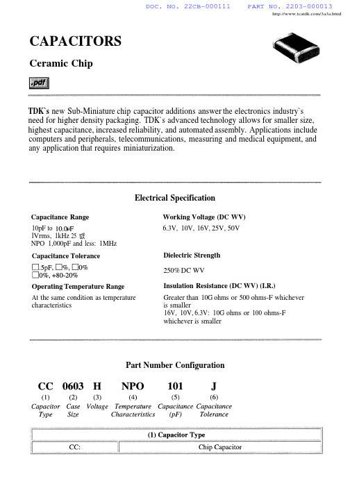
/3a3a.htmlCAPACITORSCeramic ChipTDK`s new Sub-Miniature chip capacitor additions answer the electronics industry`s need for higher density packaging.TDK`s advanced technology allows for smaller size,highest capacitance,increased reliability,and automated assembly.Applications include computers and peripherals,telecommunications,measuring and medical equipment,and any application that requires miniaturization.Capacitance Range10pF tolVrms,1kHz 25NPO 1,000pF and less:1MHzCapacitance Tolerance Operating Temperature RangeAt the same condition as temperaturecharacteristics Working Voltage (DC WV)6.3V,10V,16V,25V,50V Dielectric Strength250%DC WVInsulation Resistance (DC WV)(I.R.)Greater than 10G ohms or 500ohms-F whichever is smaller16V,10V,6.3V:10G ohms or 100ohms-Fwhichever is smallerElectrical SpecificationPart Number ConfigurationDOC. NO. 22CB-000111PART NO. 2203-000013DOC. NO. 22CB-000111PART NO. 2203-000013/3a3a.htmlCeramic Capacitors CAPACITANCE TEMPERATURE CHARACTERISTICS Class IMULTILAYER CERAMIC CHIP CAPACITORSC TYPE [16,25,50Vdc],CLASS I AND CLASS IIClass IICAPACITANCE AND TOLERANCE3-1DOC. NO. 22CB-000111PART NO. 2203-000013Ceramic CapacitorsCAPACITANCE RANGEClass I 25Vdc Class II 16Vdc50Vdc25Vdc50Vdc 3-2Ceramic CapacitorsC TYPE[BASEMETAL ELECTRODE,16,25,50Vdc],CLASS IICAPACITANCE RANGE16Vdc50VdcHC TYPE[LARGECAPACITANCE,16,25,50,75Vdc],CLASS II HIGH DIELECTRIC CONSTANTCAPACITANCE RANGE(Operating temperature range:-25to+85o C[-13 to +185o F])l6Vdc50Vdcc25Vdc 75Vdc3-3Ceramic CapacitorsC TYPE [HIGH VOLTAGE]CLASS I [3kVd c] AND CLASS II [500Vdc,1k,2kVdc]Class I CAPACITANCE TEMPERATURE CHARACTERISTICS CAPACITANCE RANGE Class I 3kVdcClass II500Vdc2kVdclkVdc3-4Ceramic Capacitors FC AND FR TYPE [LOW LOSS FOR VHF/UHF]CLASS I [50,100,200,300,500Vdc]AND CLASS II [50Vdc]Multilayer Ceramic Capacitors for high frequency and low loss are designed for 100to 1000MHz power circuit applications.FC type FR typeCAPACITANCE RANGE (Operating temperature range:-55to +l25o C [-67to +257o F])Class I Class II 50,100,200,300,500Vdc 50VdcCAPACITANCE AND TOLERANCE3-5DOC. NO. 22CB-000111PART NO. 2203-000013。
ALCATEL传输设备简明维护手册

2X140M/155M 电支路盘前面板图
--A绿灯—机盘投入使用指示 红灯---机盘内部故障指示
时钟盘前面板图
--Alcatel--
13/76
1 红灯—机盘内部故障指示 注意:一个子架上至少需要一块时钟盘,设备才能正常工作。
公务盘前面板图
--Alcatel--
14/76
中国联通全国干线网
ALCATEL设备日常维护建议
阿尔卡特传输设备简明维护手册 (Alcatel)
阿尔卡特传输系统部
目录
阿尔卡特设备简介…………………………………………………………………………………5 1664SM……………………………………………………………………………………5 设备简介………………………………………………………………………….5 设备面板图……………………………………………………………………….5 机盘示意图……………………………………………………………………….9 设备部分指标……………………………………………………………………21 1666SR…………………………………………………………………………………...26 设备简介………………………………………………………………………….26 设备面板图……………………………………………………………………….27 机盘示意图……………………………………………………………………….30 设备部分指标…………………………………………………………………….37 1650SMC………………………………………………………………………………….41 设备简介………………………………………………………………………….41 设备面板图……………………………………………………………………….44 机盘示意图……………………………………………………………………….45 日常维护注意事项………………………………………………………………………………….55 一些基本维护操作………………………………………………………………………………….56 机盘的插拔…………………………………………………………………………………56 公务话机的使用……………………………………………………………………………57 机盘的复位…………………………………………………………………………………57 硬件告警信号的处理………………………………………………………………………58 故障处理的基本方法………………………………………………………………………59 故障处理流程………………………………………………………………………………60 售后服务联系………………………………………………………………………………61
定扭扳手操作手册(中文)

数字显示扭矩角度扳手型号 CTA2操作手册致用户:请在使用之前仔细阅读本说明书,请按说明书要求正确使用此产品。
若有任何问题,请与东日公司认可的销售店或东日制作所联系。
请使用本操作手册中记载的专业充电器和蓄电池。
——请勿使用本操作手册规定之外的充电器和蓄电池。
请正确充电。
请使用本操作手册中指定的充电器。
——避免引起异常发热或导致失火。
请勿在低于0℃或高于40℃的环境下对电池进行充电。
——避免电池爆裂或引起失火。
请将电池置于通风的地方进行充电。
请勿用衣服等物品遮盖正在充电的充电器或电池。
——避免电池爆裂或引起失火。
请在充电器不使用时,将插头从电源插座中拔离,以防发生触电和失火。
请注意工具使用场所的周围情况:请勿在雨中或湿润的环境中使用此扭力扳手、充电器和电池。
——避免发生触电或引起失火。
保持良好的工作环境,避免发生意外。
——请勿在光线不足的地方使用此扭力扳手,避免发生意外。
请勿在有易燃液体或气体的环境下使用或充电。
——避免发生爆炸或引起失火。
、请勿使用本操作手册指定之外的附件,这是最基本的要求。
——避免发生爆炸或造成其他严重事故。
请勿将电池投入火中。
——避免电池爆裂和有害物质的泄漏。
① 请保持工作场所的整洁。
在脏乱的工作环境中工作容易造成意外。
② 请勿让小孩接近工具使用场所。
请勿让未经培训的人员操作此扳手,避免发生意外。
③ 若工具不被使用时,请放置在安全的地方。
应将工具放置在不易被小孩接触到的干燥的地方,避免发生意外。
请勿将此扭力扳手主体和电池置于温度高于50℃的场所。
否则容易造成电池老化,甚至引起自燃。
④ 请勿超出工具的扭矩范围使用。
为确保安全和有效使用此工具,请在此工具的扭矩范围内使用。
若超出此工具的扭矩范围使用,容易造成意外。
⑤ 请选用合适的工具型号。
请勿将此工具用于此操作手册说明外的用途。
避免发生意外。
⑥ 请勿粗暴对待充电器的电缆。
请勿用拉扯电缆的方法将充电器从电源插座中拔离。
请勿让电缆处于有外力、有油等可能造成损坏的地方避免发生触电或引起失火。
CTA11ASP12中文资料

Distributor: Electro-Stock Tel: 630-682-1542 Fax: 630-682-1562FEATURES:• Switching capacity up to 25A • Small size and light weight• PCB pin and quick connect mounting available • Suitable for automobile and lamp accessories • QS-9000, ISO-9002 Certified Manufacturing22.8 x 15.3 x 25.8 mmCONTACT DATAContact Arrangement 1A = SPST N.O. 1C = SPDTContact Rating1A: 25A @ 14VDC 1C: 20A @ 14VDC Contact Resistance < 50 milliohms initial Contact MaterialAgSnO 2 Maximum Switching Power 350W Maximum Switching Voltage 75VDC Maximum Switching Current25ACOIL DATACoil VoltageVDCCoil ResistanceΩ ± 10%Rated Max. 1.2W 1.5W Pick Up Voltage VDC (max)75%of rated voltage Release Voltage VDC (min)10%of rated voltageCoil PowerWOperate TimemsRelease Timems6 7.8 30 24 4.20.6 12 15.6 120 96 8.41.2 24 31.2 480 384 16.82.4 48 62.4 1920 1536 33.64.81.2 or 1.5 10 7CAUTION:1. The use of any coil voltage less than the rated coil voltage may compromise the operation of the relay.2. Pickup and release voltages are for test purposes only and are not to be used as design criteria.GENERAL DATAElectrical Life @ rated load Mechanical Life 100K cycles, typical 10M cycles, typical Insulation Resistance 100M Ω min @ 500VDCDielectric Strength, Coil to Contact Contact to Contact 2500V rms min. @ sea level 1500V rms min. @ sea level Shock Resistance 100m/s 2 for 11ms Vibration Resistance 1.27mm double amplitude 10-40Hz Terminal (Copper Alloy) Strength 8N (Quick Connect), 4N (PCB Pins) Operating Temperature Storage Temperature -40 °C to + 85 °C -40 °C to + 155 °C Solderability 230 °C ± 2 °C for 10 ± 0.5sWeight 18.5gDistributor: Electro-Stock Tel: 630-682-1542 Fax: 630-682-1562ORDERING INFORMATION1. Series:CTA1CTA12.Contact Arrangement:1A=SPST N.O. 1C=SPDT1A3. Sealing Options: S = Sealed C = Dust Cover S4. Termination: P = PCB PinsQ = Quick Connect Q5. Coil Voltage: 6VDC 12VDC 24VDC 48VDC126. Coil Power: 1.2 = 1.2W 1.5 = 1.5W1.27. Coil Suppression: Blank = Standard D = Diode (1N4005)R = Resistor (680 Ohms)** Consult factory if other values are needed.DIMENSIONS (Units = mm) PC PIN DIMENSIONS (Units = mm)SCHEMATICS & PC LAYOUT (BOTTOM VIEWS)1A 1C。
CTA1中文资料
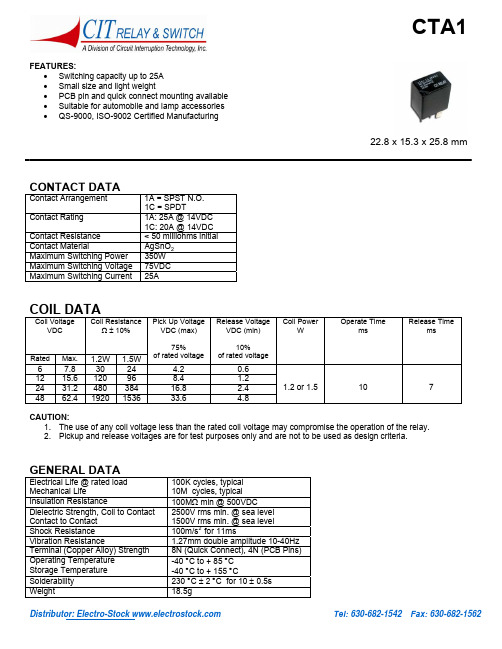
Distributor: Electro-Stock Tel: 630-682-1542 Fax: 630-682-1562FEATURES:• Switching capacity up to 25A • Small size and light weight• PCB pin and quick connect mounting available • Suitable for automobile and lamp accessories • QS-9000, ISO-9002 Certified Manufacturing22.8 x 15.3 x 25.8 mmCONTACT DATAContact Arrangement 1A = SPST N.O. 1C = SPDTContact Rating1A: 25A @ 14VDC 1C: 20A @ 14VDC Contact Resistance < 50 milliohms initial Contact MaterialAgSnO 2 Maximum Switching Power 350W Maximum Switching Voltage 75VDC Maximum Switching Current25ACOIL DATACoil VoltageVDCCoil ResistanceΩ ± 10%Rated Max. 1.2W 1.5W Pick Up Voltage VDC (max)75%of rated voltage Release Voltage VDC (min)10%of rated voltageCoil PowerWOperate TimemsRelease Timems6 7.8 30 24 4.20.6 12 15.6 120 96 8.41.2 24 31.2 480 384 16.82.4 48 62.4 1920 1536 33.64.81.2 or 1.5 10 7CAUTION:1. The use of any coil voltage less than the rated coil voltage may compromise the operation of the relay.2. Pickup and release voltages are for test purposes only and are not to be used as design criteria.GENERAL DATAElectrical Life @ rated load Mechanical Life 100K cycles, typical 10M cycles, typical Insulation Resistance 100M Ω min @ 500VDCDielectric Strength, Coil to Contact Contact to Contact 2500V rms min. @ sea level 1500V rms min. @ sea level Shock Resistance 100m/s 2 for 11ms Vibration Resistance 1.27mm double amplitude 10-40Hz Terminal (Copper Alloy) Strength 8N (Quick Connect), 4N (PCB Pins) Operating Temperature Storage Temperature -40 °C to + 85 °C -40 °C to + 155 °C Solderability 230 °C ± 2 °C for 10 ± 0.5sWeight 18.5gDistributor: Electro-Stock Tel: 630-682-1542 Fax: 630-682-1562ORDERING INFORMATION1. Series:CTA1CTA12.Contact Arrangement: 1A=SPST N.O. 1C=SPDT1A3. Sealing Options: S = Sealed C = Dust Cover S4. Termination: P = PCB PinsQ = Quick Connect Q5. Coil Voltage: 6VDC 12VDC 24VDC 48VDC126. Coil Power: 1.2 = 1.2W 1.5 = 1.5W1.27. Coil Suppression: Blank = Standard D = Diode (1N4005)R = Resistor (680 Ohms)** Consult factory if other values are needed.DIMENSIONS (Units = mm) PC PIN DIMENSIONS (Units = mm)SCHEMATICS & PC LAYOUT (BOTTOM VIEWS)1A 1C。
Alcatel1521中文说明书资料

Alcatel 1521中文说明书北京惟帆通讯设备有限公司2001年8月目录一、概述 (3)二、设备特点 (3)三、系统应用 (3)四、系统描述 (5)五、功能描述 (6)5.1 透明的传输模式(Transparent Transmission Mode) (6)5.2 ISDN PRA传输模式 (6)5.3 专线模式(SLL) (7)5.4 X.21数据传输模式 (7)六、设备维护描述 (8)6.1 设置 (9)6.2系统保护 (9)七.设备的物理特性 (9)7.1 Alcatel 1521FL S9机框物理描述 (9)7.2 Alcatel 1521FL DT的物理描述 (12)7.3手持终端HHT的物理描述 (12)八、设备安装 (13)8.1 Alcatel 1521FL S9机框的安装 (13)8.2 Alcatel 1521FL DT的安装 (13)8.3 Alcatel 1521FL系统运行 (13)九、系统技术数据 (14)9.1 光模块组件 (14)9.2 光功率 (14)9.3 2 Mbit/s接口 (14)9.4 辅助数据通道 (14)9.5 光接口 (15)9.6 告警接口 (15)9.7 电源指标 (15)9.8 机械规格 (15)9.9 环境规范 (16)9.10 MTBF (16)一、概述在未来的宽带BISDN的发展中,高带宽,大数据容量对光传输越来越成为主流的发展方向,在支持当前的宽带业务中,发展N×2M的光纤线路将具有最佳的投资效益.Alcatel 1521 FL是4*2Mbit/s光纤接入系统。
属于Alcatel接入产品系列。
同时,1521FL 也适用于短距离或中等距离的干线传输。
在一对单模光纤双向传输数据(传输距离50KM),也可以采用波分复用的技术在单根光纤进行双方向传输数据(传输距离30KM)。
Alcatel 1521 FL终端设备中集成了4*2Mbit/s多路复用器和光传输模块。
CTC-PAL进样器中文说明书
版次 1999年2月第一版软件版本2.0本操作手册内容如经修改,不作另行通知。
CTC Analysis AG公司对本材料不做任何形式的保证,包括但不限于,暗示性保证或对特定目的商品性能及适应性。
CTC Analysis AG公司在提供或应用本材料时,对手册中包含的错误或对偶然和必然损失不负任何责任。
未经许可并得到版权所有者的书面同意,本出版物的内容(包括电子形式的存储,修订以及翻译为外语)不允许以任何形式或任何手段翻印。
1999年出版 CTC Analysis AG公司瑞士出版版权保留安全知识遵守规则请阅读与本仪器有关的遵守规则。
电气危险每个分析仪器都有特定的危险性。
因此请一定要阅读并遵循以下预防措施。
它们将帮助你确保安全,延长combi PAL 系统的使用寿命。
请使用与仪器型号和电流相同的保险丝。
不要使用损坏过又被修复的保险丝,不要短接保险丝支架。
电源线必须插入一个具有保护接地的电源插座上。
当使用加长的电源线时,必须确保该线也与地线相接。
不要改变外部或内部的保护连接。
损坏或切断这些连接可能对人造成危险,对combi PAL 系统造成损坏。
本仪器在运输前已照章正确接地。
为了确保安全操作,您不需要对电路连接或仪器底座做任何改变。
当您怀疑已经有任何电气损坏时,不要启动仪器电源。
而要断开电源线的连接并与combi PAL公司销售代表联系,进行仪器评估。
在仪器评估完成前不要试图使用仪器。
如果combi PAL 操作系统显示出可见的损害信号或者已经在严重的情况下运输,则仪器可能出现了损害。
仪器长时间放置于在不良的环境条件下也可引起损坏。
在进行任何维修前必须拨掉电源线。
即使关机,仪器内部的电容器可能仍然充满电荷。
仪器中有许多积分线路,当它们的线电压波动过大或遭到电源冲击中,这些线路可能损坏。
在没有CTC Analysis AG公司代表的参与时,不要试图修理或更换本手册中未描述的任何仪器部件。
加热区Combi PAL加热区能达到的最高温度为200℃。
卡特克-阿尔滤筒系列产品说明说明书
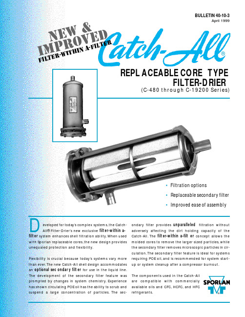
eveloped for today’s co m p l e x sys t e m s ,the Catc h -All® Fi l t e r -D ri e r ’s new exc l u s i v e f i l t er-within a-f i l t er s y s t em enhances shell filtration ability.When used with Spo r lan re p l a c eable co r e s ,the new design prov i d e s unequaled pro t e c tion and flex i b i l i t y.Fl e x i b i l i t y is crucial be c ause tod a y’s sys t ems va r y more than eve r .The new Catc h -A ll shell design acco m m o d a te s an optional sec o n d a r y filt e r for use in the liquid line.The deve l o p m e n t of the seco n d a r y filter fe a t u r e wa s p r o m p t ed by changes in sys t em chemistry.E x p e r i e n c e has shown circ u l a ting POE oil has the ability to scrub and s u s p end a large co n c e n t r ation of part i c l e s .The sec-o n d a r y filter provides u n p a r a l l e l e d f i l t r ation without a d versely affe c ting the dirt holding ca p a c i t y of the Catc h -A l l .The f i l t er-within a-filt e r co n c ept allows the molded co r es to re m o ve the larger sized part i c l e s ,w h i l e the seco n d a r y filter re m o ves micro s c opic particles in cir-c u l a t i o n .The seco n d a r y filter fe a t u r e is ideal for sys t e m s re q u i r ing POE oil,and is re c ommended for sys t em start-up or sys t em cleanup after a co m p r e s s o r b u r n o u t .The co m p o n e n ts used in the Catc h -A l l a r e co m p a tible with co m m e r c i a l l y available oils and CFC,H C F C ,and HFC re f r i g e r a n t s .BULLETIN 40-10-3April 1999REPL ACEABLE CORE TYPEFILTER-DRIER(C-480 through C-19200 Se r i e s)Integral to the redesign are these…DESIGN FEATURES•The Catch-All shell utilizes an exclusive filter-within a-filter construction . The new internal assembly,when used with Sporlan molded cores, provides maximum water capacity, excellent acid removal charac-teristics, the ability to remove products of oil decomposition, and outstanding filtration. The optional replaceable secondary filter offers unsurpassed filtration efficiencies without compromising the Catch-AllÕs ability to hold a large amount of foreign material. The assembly is designed so the cores remove larger sized particles while the secondary filter removes microscopic particles. This unique construction aggressively filters particles circulating in a refrigerant system.•The shell redesign offers flexibility . The new internal assembly can be used with or without the secondary filter. The type of fil-tration needed depends upon the system requirements or appli-cation. Using the assembly without the secondary filter offers the same time tested, field-proven, filtration characteristics expected in a Catch-All Filter-Drier.•The internal construction is designed to improve ease of assem-bly . The molded cores simply slide over the center tube, fol-lowed by spacer plates (if applicable). The outlet plate is fastened to the assembly by a wing screw. With the addition of a spring, the resulting assembly is easy to install and remove.•The seal gasket prevents solid contaminants from bypassing the filter. The assembly is held tight against the gasket by a spring.O-rings are used with the secondary filter to provide a tight seal.•The internal parts are plated steel Ð no plastic parts.•The bolt and nut attachment of the end plate allows for simple,trouble-free installation. The nuts lock against the side of the shell for ease in tightening. Other designs, using cap screws threaded into the flange ring, run the risk of twisting off the head of the screw making removal difficult.•Copper fittings are excellent for fast easy soldering. Fittings are pre-sized for proper fit, and suitable for use with soft solder, sil-ver solder, Sil-Fos, or Phos-Copper. The fittings are brazed to the shell with a high temperature brazing alloy so they never come loose during the brazing operation on the job.•A complete line of fitting sizes are available with solder con-nections from 1/2Ó to 2-1/8Ó ODF.•Heavy steel shells provide high bursting strength and are listed by UnderwritersÕLaboratories Inc. and Canadian Standards Association.•The shell exterior uses an epoxy powder coating to prevent corrosion even under the most adverse condi-tions.Page 2/ BULLETIN 40-10-3The construction illustrated is used on the C-480 through C-19200 Series Catch-All Filter-Driers (ODF Solder models only)manu f actured a f ter 6/99.The C-R420,C-30,000,and C-40,000 Series models differ in construction,but maintain the f ield-proven features which have been used suc-cessfully for many years.C-967Exploded ViewFEATURES®BULLETIN 40-10-3 / Page 3APPLICATIONThe C-480 through C-19200 Series Replaceable Core Type Catch-All Filter-Driers are designed to be used in the liquid line. Place the Catch-All immediately ahead of other liquid line controls, such as the ther-mostatic expansion valve, solenoid valve, and See¥All¨Moisture and Liquid Indicator. When applied in this way, the filter-drier provides maximum protection for the thermostatic expansion valve and solenoid valve from dirt that may be in the system. If the system contains appreciable amounts of moisture, this location gives the best results in protecting the thermostatic expansion valve from freeze-up. If possi-ble, place the filter-drier in a cold location on the liq-uid line. Acid capacity is not affected by differences in liquid line temperature.The secondary filter feature is ideal for systems with POE oil, and is recommended for system start-up or system cleanup after a compressor burnout.Because of flow considerations, the new C-480 through C-19200 Series Replaceable Core Type Catch-All Filter-Driers are not recommended for the suction line. Sporlan manufactures Replaceable Suction Filter(RSF) shells specifically for suction line installations. The RSF shell is designed to allow maximum vapor flow with a minimum pressure drop whether the installer is using filter elements or mold-ed cores.Catch-All Filter-Driers are not recommended in the discharge line. There are better locations. The water capacity in this location is greatly reduced due to the high operating temperature.Catch-All Filter-Driers may be installed in any position, with top or bottom feed. However, it is advisable to mount replaceable core models horizontally so that for-eign material cannot drop into the outlet fitting when the cores are removed. Always observe the flow direction. Catch-Alls must never be subjected to reverse flow.The Catch-All should be installed in the main liquid line for maximum protection. When located in a bypass line, dirt or foreign material may pass into the system through the unprotected line. When a bypass installation is necessary, consult Bulletin 40-10.The components used in the Catch-All are compatible with commercially available CFC, HCFC, and HFC refrigerants and oils. The new internal assemblies are not suitable for use on ammonia systems. All Replaceable Core Type Catch-All Filter-Driers with NPT female connections, supplied with the tie rod construction, are suitable for CFC, HCFC, and HFC refrigerants plus ammonia.SELECTIONThe C-480 through C-19200 Series Catch-All Filter-Driers should be selected in accordance with the Liquid Refrigerant Flow Capacities and Selection Recommendations in Bulletin 40-10. Catch-All shells incorporating the new construction, even with the sec-ondary filter, have liquid flow capacities equal to or slightly greater than the shells using the tie rod con-struction.Water and acid capacities of the Replaceable Core Type Catch-Alls have not changed. Consult Bulletin 40-10 on the water capacities of these models at ARI Standard Conditions. Acid removal is difficult to measure. There are no standard ratings to follow. However, both labo-ratory and field tests have demonstrated that the Catch-All core has far superior acid removal ability Ð many times that available in other driers.Filtration characteristics of a filter-drier are not readily defined or evaluated since laboratory tests cannot accu-rately reproduce the range of conditions and contami-nants seen in an actual system. The ability to filter and hold foreign matter varies with the brand and type of fil-ter-drier. The simplest guide to follow is that filter capacity is proportional to filtering area. Filters should be selected with an adequate reserve capacity to allow for the contamination found in most systems.APPLICATION / SELECTION ®Page 4/ BULLETIN 40-10-3* Two O-rings are required for each internal assembly and are sup-plied with each secondary filter.The O-rings,part no.621-025,can also be purchased separately.Previous Designs –Parts kits for the new internal construction fit in shell Designs B and C.Converting shell Design B does require a thicker outlet retainer ring plate gasket,part no.1288-014.The new internal construction cannot be used in Design A.Consult Bulletin 122 for replacement part specifications for Design A.R eplacement Parts and Kits are available through Sporlan Authorized Wholesalers.AssemblyOptional Secondary FilterShellFlange Bolts and NutsDesign DManufactured June 1999P RINTEDINU.S. OF A. ©C OPYRIGHT 1999 S PORLAN V ALVE C OMPANY , W ASHINGTON , M ISSOURI 15-499Design AManufactured until 1983Design B )Manufactured 1983-1991)Manufactured 1991 - Present(“Press Fit”onto Plate,Outlet Core Retainer)NutShellare included)Tie Rod(3 Req’d)Outlet Screen Gasket (Felt)Tie Rod(3 Req’d)Tie Rod(3 Req’d)Nut NutPlate Gasket)The B and C design can be differentiated by external shell appear-ance. The welded end cap on the outlet of the shell fits inside the body shell on the B version and it slides over the body shell on the C version.(“-P”Type Catch-Alls Only)Retainer Plate Gasket。
阿尔法拉夫超级纯度压力传感器说明书
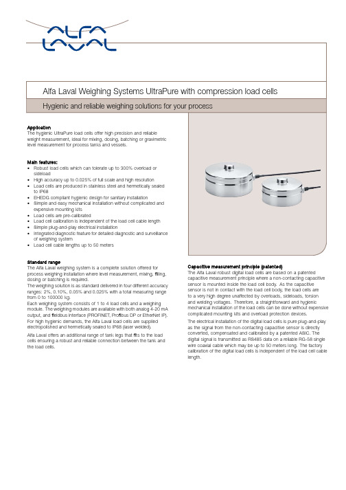
Standard rangeThe Alfa Laval weighing system is a complete solution offered for process weighing installation where level measurement,mixing,filling, dosing or batching is required.The weighing solution is as standard delivered in four different accuracy ranges:2%,0.10%,0.05%and0.025%with a total measuring range from0to100000kg.Each weighing system consists of1to4load cells and a weighing module.The weighing modules are available with both analog4-20mA output,andfieldbus interface(PROFINET,Profibus DP or EtherNet IP). For high hygienic demands,the Alfa Laval load cells are supplied electropolished and hermetically sealed to IP68(laser welded).Alfa Laval offers an additional range of tank legs thatfits to the load cells ensuring a robust and reliable connection between the tank and the load cells.Capacitive measurement principle(patented)The Alfa Laval robust digital load cells are based on a patented capacitive measurement principle where a non-contacting capacitive sensor is mounted inside the load cell body.As the capacitive sensor is not in contact with the load cell body,the load cells areto a very high degree unaffected by overloads,sideloads,torsionand welding voltages.Therefore,a straightforward and hygienic mechanical installation of the load cells can be done without expensive complicated mounting kits and overload protection devices.The electrical installation of the digital load cells is pure plug-and-play as the signal from the non-contacting capacitive sensor is directly converted,compensated and calibrated by a patented ASIC.The digital signal is transmitted as RS485data on a reliable RG-58single wire coaxial cable which may be up to50meters long.The factory calibration of the digital load cells is independent of the load cell cable length.Technical DataMeasuring range:..............from0to100000kgdepending on systemselection. Accuracy:..................2%,0.10%,0.05%,0.025% Compensated temperature range:...-10to50°COverload and sideload:300%at300kg capacity systems and100%at32000t capacity systemsPower:Power supply:...............24VDC±10%,min.2A Mechanical dataWeight:Load cell:CL type.................... 1.8kgCM type.................... 3.6kgWeighing modules:............approx.0.5kg Materials:Load cells:..................AISI316and17-4PH Operating temperature range:Load cells:..................-50to70°C(100°C withteflon cable)Weighing modules:............-10to50°CProtection class:Load cells:..................IP68Weighing modules:............IP20CertificatesCE marked3.1B certificateCalibration certificate(Option)SpecificationsParameter Unit0.1%0.05%0.025%*Rated capacity(Emax)per load cell kgCL:50,100,150,250,500,1000,1500,2000,3000,4000,5000CM:6000,8000,10000,15000,20000,25000Safe overload limit%of E max200to500Safe sideload limit%of E max300to1000Minimum dead load%of E max0Accuracy%of E max0.1000.0500.025 Repeatability%of E max0.0300.0200.012 Hysteresis%of E max0.0550.0400.020 Creep30min.%of E max0.0600.0400.025 Temperature effect on zero%/10°C0.0600.0450.030 Temperature effect on sensitivity%/10°C0.0600.0450.030 Deflection at Emax mm max.0.2Mesuring rate Hz500Supply Vdc24Vdc±10%Internal resolution Bit24Maximum cable length m100Output options PROFINET,Profibus DP,DeviceNet, EtherNet/IP,RS485,4-20mA2%accuracy system includes active and dummy load cells *0.025%accuracy is available up to5000kg.Options Output:4-20mA PROFINET EtherNet IP Pro fibus DP RS485Local weighing display:Alfa Laval weighing terminal Load cell cable:6m standard coaxial RG58with BNC connector (option:10,20or 50m)Dimensional drawingsCL load cell (50-5000kg)CM load cell (6000-25000kg)+0.0Hygienic Baseplate for CL load cell Hygienic baseplate for CM loadcellCL load cell installation with tank legCM load cell installation with tank legAccessoriesTank legs to compression load cells9614460901tank feet M30for load cells below11000kg with short spindel9614460905tank feet M36for load cells below16000kg with short spindel9614460902tank feet M42for load cells below21500kg with short spindel9614460903tank feet M56for load cells below37000kg with short spindelLayout and electrical connection schematic of weighing modules:Profinet weighing module for4load cells(external dimensions is the same for Profibus DP and Ethernet IP4-20mA output weighing module for4load cellsRS485interface module(when ordered with display)14mm/5.51in128mm/5.4in116mm/4.57in11mm/.43in29 mm / 1.14 in60 mm / 2.36 inø4.5 mm / ø0.18 in66 mm / 2.60 inStainless steel enclosureEnclosure when ordered without display.Enclosure with displaySelection guideWhen configuring a weighing system,you need the following information:•Number of tank legs or supporting points•Total weight of tank incl.product in kg•Required output and/or local display•Required accuracy for the application(e.g.dosing,mixing,level measurement etc.)With this information,you are able tofind the configuration you need in the ordering leaflet or in the online configuration tool. Step1:Calculate the total weight of the tank including the product in kg and round up to the nearest standard load cell system. Step2:Decide on accuracy required by the application-2%accuracy systems are suitable for level measurement applications-0.10%accuracy systems are suitable for mixing applications-0.05%accuracy systems are suitable for dosing applications-0.025%accuracy systems are suitable for very precise dosing and batching applicationsStep3:Decide on the output signal type and/or a local weighing display:-4-20mA-PROFINET-EtherNet IP-Profibus DPStep4:Decide if you want the display and/or weighing modules supplied mounted in a stainless steel enclosureYou have the following options:-Without stainless steel enclosure-Weighing module mounted in stainless steel enclosure(without display)-Display mounted in stainless steel enclosureStep5:Decide on the length of the load cell cables(the length of the cable is can be shortened without the need for recalibration)-6m(standard)-10m-20m-50mStep6:Decide on if you need calibration certificateTheoretical statistical weighing system accuracyNumber ofSystem range System range loadcells and System type System type System type Item nr3legs4legs lc-type in system0.10%0.05%0.025% TE67WC0xxxxxxxx0-300kg..(3*100kg lc)±0.17kg.±0.09kg.±0.04kg. TE67WC1xxxxxxxx0-400kg.(4*100kg lc)±0.20kg.±0.10kg.±0.05kg. TE67WC4xxxxxxxx0-750kg.(3*250kg lc)±0.43kg.±0.22kg.±0.11kg. TE67WC5xxxxxxxx0-1000kg.(4*250kg lc)±0.50kg.±0.25kg.±0.13kg. TE67WC6xxxxxxxx0-1500kg.(3*500kg lc)±0.87kg.±0.43kg.±0.22kg. TE67WC7xxxxxxxx0-2000kg.(4*500kg lc)±1.00kg.±0.50kg.±0.25kg. TE67WC8xxxxxxxx0-3000kg.(3*1000kg lc)±1.73kg.±0.87kg.±0.43kg. TE67WC9xxxxxxxx0-4000kg.(4*1000kg lc)±2.00kg.±1.00kg.±0.50kg. TE67WCBxxxxxxxx0-6000kg.(3*2000kg lc)±3.46kg.±1.73kg.±0.87kg. TE67WCCxxxxxxxx0-8000kg.(4*2000kg lc)±4.00kg.±2.00kg.±1.00kg. TE67WCDxxxxxxxx0-9000kg.(3*3000kg lc)±5.20kg.±2.60kg.±1.30kg. TE67WCExxxxxxxx0-12000kg.(4*3000kg lc)±6.00kg.±3.00kg.±1.50kg. TE67WCExxxxxxxx0-12000kg.(3*4000kg lc)±6.93kg.±3.46kg.±1.73kg. TE67WCGxxxxxxxx0-16000kg.(4*4000kg lc)±8.00kg.±4.00kg.±2.00kg. TE67WCFxxxxxxxx0-15000kg.(3*5000kg lc)±8.66kg.±4.33kg.±2.17kg. TE67WClxxxxxxxx0-20000kg.(4*5000kg lc)±10.00kg.±5.00kg.±2.50kg. TE67WCHxxxxxxxx0-18000kg.(3*6000kg lc)±10.39kg.±5.20kg.N/ATE67WCJxxxxxxx0-24000kg.(4*5000kg lc)±12.00kg.±6.00kg.N/ATE67WCJxxxxxxx0-24000kg.(3*8000kg lc)±13.86kg.±6.93kg.N/ATE67WCKxxxxxxx0-32000kg.(4*8000kg lc)±16.00kg.±8.00kg.N/ATE67WCNxxxxxxx0-30000kg.(3*10000kg lc)±17.32kg.±8.66kg.N/ATE67WCOxxxxxxx0-40000kg.(4*10000kg lc)±20.00kg.±10.00kg.N/ATE67WCPxxxxxxx0-45000kg.(3*15000kg lc)±25.98kg.±12.99kg.N/ATE67WClxxxxxxx0-60000kg.(4*15000kg lc)±30.00kg.±15.00kg.N/ATE67WClxxxxxxx0-60000kg.(3*20000kg lc)±34.64kg.±17.32kg.N/ATE67WCSxxxxxxx0-80000kg.(4*20000kg lc)±40.00kg.±20.00kg.N/ATE67WCTxxxxxxx0-75000kg.(3*25000kg lc)±43.30kg.±21.65kg.N/ATE67WCUxxxxxxx0-100000kg.(4*25000kg lc)±50.00kg.±25.00kg.N/AAlfa Laval reserves the right to change specifications without prior notification.How to contact Alfa Laval Contact details for all countriesare continually updated on our website.Please visit to access the information direct.A l f a L a v a l i s a t r a d e m a r k r e g i s t e r e d a n d o w n e d b y A l f a L a v a l C o r p o r a t e AB . 100001051e n 1908。
Alcatel-Lucent CorbaNBI 1.6 接口规范说明书
Alcatel-Lucent1359 CorbaNBI | Release 1.6Interface Specification8DG 34000 AAAA TQ ZZAJanuary 2010Issue 41359CORBA NBI 1.5- Interface Specification8DG 34000 AAAATQZZA Ed. 4 Status: RL Author: Chen Min Page 2 / 268 *** PRINTED and DISTRIBUTED COPIES ARE UNCONTROLLED ***Electronic originals available in Optics PDMAll rights reserved. Passing on and copying of this document, use and communication of its content not permitted withoutwritten authorisation from Alcatel-LucentCORBANBI 1.6 INTERFACE SPECIFICATIONAuthor: CORBA NBI System team8DG 34000 AAAA TQZZARevision HistoryED Date Comments Author Appraisal authority 1.1 2009-10-27 Creation Liu Liu Tang Tie1.2 2009-10-30 Modification Wu liang Tang Tie1.3 2009-11-1 Modification Cui Kai Tang Tie1.4 2010-01-18 Modification Wu liang Tang TieTable of ContentsCorbaNBI 1.6 Interface Specification (3)HISTORY (15)OPEN ISSUES (16)Purpose and scope (16)Referenced Documents (17)1.GLOSSARY AND DEFINITIONS (18)1.1.Definitions (18)1.2.Abbreviations (18)2.INTRODUCTION (19)2.1.Document scope (19)3.ARCHITECTURAL DESCRIPTION (20)4.INTERFACE DESCRIPTION (21)5.DESIGN CHOICES (22)6.Data Type Description (23)6.1.1.AssignedSeverity_T (23)6.1.2.AlarmSeverityAssignment_T (23)6.1.3.AlarmSeverityAssignmentList_T (24)6.1.4.ASAP_T (24)6.1.5.ASAPList_T (26)6.1.6.ASAPCreateModifyData_T (26)6.1.7.Capability_T (27)6.1.8.CapabilityList_T (27)6.1.9.EMS_T (27)6.1.10.managerNames_T (28)6.1.11.EquipmentObjectType_T (28)6.1.12.EquipmentObjectTypeList_T (29)6.1.13.ServiceState_T (29)6.1.14.EquipmentHolderType_T (29)6.1.15.HolderState_T (29)6.1.16.Equipment_T (30)6.1.17.EQTCreateData_T (32)6.1.18.EquipmentHolder_T (32)6.1.19.EquipmentTypeQualifier_T (33)6.1.20.EquipmentOrHolder_T (34)6.1.21.EquipmentOrHolderList_T; (34)AndStringValue_T (34)6.1.23.NVSList_T (34)6.1.24.NamingAttributes_T (34)6.1.25.NamingAttributesList_T (35)6.1.26.Time_T (35)6.1.27.ConnectionDirection_T (35)6.1.28.ExceptionType_T (35)6.1.29.ProcessingFailureException (37)6.1.30.ServerLaunchCapability_T (37)6.1.31.GuiCutThroughData_T (38)6.1.32.GuiCutThroughDataList_T (38)6.1.37.CurrentMaintenanceOperationList_T (40)municationState_T (40)6.1.39.ManagedElement_T (40)6.1.40.ManagedElementList_T (42)6.1.41.Topology_T (42)6.1.42.EMSFreedomLevel_T (43)6.1.43.MultiLayerSubnetwork_T (43)6.1.44.SubnetworkList_T (44)6.1.45.TPPoolCreateData_T (44)6.1.46.ProtectionSchemeState_T (45)6.1.47.ProtectionType_T (45)6.1.48.SwitchReason_T (46)6.1.49.ESwitchReason_T (46)6.1.50.ProtectionCommand_T (46)6.1.51.ProtectionGroupType_T (46)6.1.52.EProtectionGroupType_T (47)6.1.53.ReversionMode_T (47)6.1.54.ProtectionGroup_T (47)6.1.55.ProtectionGroupList_T; (48)6.1.56.EProtectionGroup_T (48)6.1.57.EProtectionGroupList_T (49)6.1.58.SwitchData_T (49)6.1.59.SwitchDataList_T (50)6.1.60.ESwitchData_T (50)6.1.61.ESwitchDataList_T (51)6.1.62.BackupId_T (51)6.1.63.BackupIdList_T (51)6.1.64.Current_OperationStatus_T (52)6.1.65.BackupStatus_T (52)6.1.66.StaticProtectionLevel_T (52)6.1.67.ProtectionEffort_T (53)6.1.68.SNCState_T (53)6.1.69.GradesOfImpact_T (53)6.1.70.TPData_T (54)6.1.71.TPDataList_T (55)6.1.72.SNCType_T (55)6.1.73.Reroute_T (55)workRouted_T (56)6.1.75.RerouteChangeEvent_T (56)6.1.76.SubnetworkConnection_T (56)6.1.77.SubnetworkConnectionList_T (58)6.1.78.CrossConnect_T (58)6.1.79.Route_T (59)6.1.80.CrossConnectList_T (59)6.1.81.Resource_T (59)6.1.82.ResourceList_T (59)6.1.83.RouteDescriptor_T (59)6.1.87.RouteNameAndAdminStateList_T (62)6.1.88.SNCCreateData_T (62)6.1.89.SNCModifyData_T (64)6.1.90.Directionality_T (66)6.1.91.TPConnectionState_T (66)6.1.92.TPType_T (67)6.1.93.TerminationMode_T (67)6.1.94.TPProtectionAssociation_T (69)6.1.95.TerminationPoint_T (69)6.1.96.TerminationPointList_T (75)6.1.97.GTP_T (75)6.1.98.GTPlist_T (76)6.1.99.GTPEffort_T (76)6.1.100.TopologicalLink_T (76)6.1.101.TopologicalLinkList_T (77)6.1.102.TLCreateData_T (78)6.1.103.ServiceCategory_T (78)6.1.104.TrafficParameterList_T (79)6.1.105.TrafficDescriptor_T (79)6.1.106.TDCreateData_T (80)6.1.107.TrafficDescriptorList_T (81)6.1.108.ServiceCategory_T (81)6.1.109.TrafficParameterList_T (81)6.1.110.TransmissionDescriptor_T (81)6.1.111.TMDCreateData_T (82)6.1.112.TransmissionDescriptorList_T (83)yerRate_T (83)yerRateList_T (84)yeredParameters_T (84)yeredParameterList_T (84)6.1.117.Destination_T (84)6.1.118.Granularity_T (84)6.1.119.GranularityList_T (85)6.1.120.PMLocation_T (85)6.1.121.PMLocationList_T (85)6.1.122.PMParameterName_T (85)6.1.123.PMParameterNameList_T (85)6.1.124.PMParameter_T (85)6.1.125.PMParameterList_T (86)6.1.126.PMThresholdType_T (86)6.1.127.PMThresholdValue_T (86)6.1.128.PMThresholdValueList_T (87)6.1.129.TCAParameter_T (87)6.1.130.TCAParameterList_T (87)6.1.131.TCAParameterProfile_T (87)6.1.132.TCAParameterProfileList_T (88)6.1.133.PMMeasurement_T (88)6.1.137.PMTPSelect_T (90)6.1.138.PMTPSelectList_T (90)6.1.139.HoldingTime_T (90)6.1.140.TCAParameters_T (91)6.1.141.AdministrativeState_T (91)6.1.142.PMThreshold_T (91)6.1.143.PMThresholdList_T (91)6.1.144.PMParameterWithThresholds_T (92)6.1.145.PMParameterWithThresholdsList_T (92)6.1.146.PMP_T (92)6.1.147.PMPList_T (93)6.1.148.PMMonitorOrReportStatus_T (93)6.1.149.PMCollectionPlan_T (93)6.1.150.PMCollectionPlanList_T (94)6.1.151.StpProtocolType_T (94)6.1.152.BridgeType_T (95)6.1.153.BridgeLogicPort_T (95)6.1.154.BridgeLogicPortList_T (95)6.1.155.VirtualBridgeParameter_T (95)6.1.156.VirtualBridge_T (97)6.1.157.VirtualBridgeList_T (98)6.1.158.Vlan_T (98)6.1.159.VlanList_T (99)6.1.160.StpMode_T (99)6.1.161.VStpPortEnable_T (99)6.1.162.VStpPortManualMode_T (99)6.1.163.VStpPortRole_T (99)6.1.164.VStpPortAdminConnectionType_T (99)6.1.165.VStpPortOperConnectionType_T (100)6.1.166.VstpPortRcvdInternal_T (100)6.1.167.VStpPortState_T (100)6.1.168.StpPortParam_T (100)6.1.169.ForwardingRecordState_T (101)6.1.170.ForwardingRecord_T (101)6.1.171.ForwardingRecordList_T (102)6.1.172.ObjectType_T (102)6.1.173.ObjectTypeQualifier_T (103)6.1.174.PerceivedSeverity_T (103)6.1.175.AcknowledgeIndication_T (103)6.1.176.AlarmTypeQualifier_T (103)6.1.177.PerceivedSeverityList_T (103)6.1.178.ServiceAffecting_T (103)6.1.179.ProbableCauseList_T (104)AndAnyValue_T (104)6.1.181.NVList_T (104)6.1.182.FileTransferStatus_T (104)6.1.183.EventList_T (104)6.1.187.CorrelatedNotifications_T (105)6.1.188.CorrelatedNotificationList_T (105)6.1.189.ProposedRepairAction_T (105)6.1.190.ProposedRepairActionList_T (105)6.1.191.AlarmId_T (105)6.1.192.TCAId_T (106)6.1.193.AlarmOrTCAIdentifier_T (106)6.1.194.AlarmAndTCAIDList_T (106)6.1.195.Destination_T (107)6.1.196.Granularity_T (107)6.1.197.GranularityList_T (107)6.1.198.PMLocation_T (107)6.1.199.PMLocationList_T (107)6.1.200.PMParameterName_T (107)6.1.201.PMParameterNameList_T (107)6.1.202.PMParameter_T (108)6.1.203.PMParameterList_T (108)6.1.204.PMThresholdType_T (108)6.1.205.PMThresholdValue_T (108)6.1.206.PMThresholdValueList_T (109)6.1.207.TCAParameter_T (109)6.1.208.TCAParameterList_T (109)6.1.209.TCAParameterProfile_T (109)6.1.210.TCAParameterProfileList_T (110)6.1.211.PMMeasurement_T (110)6.1.212.PMMeasurementList_T (111)6.1.213.PMData_T (111)6.1.214.PMDataList_T (111)6.1.215.PMTPSelect_T (112)6.1.216.PMTPSelectList_T (112)6.1.217.HoldingTime_T (112)6.1.218.TCAParameters_T (112)6.1.219.AdministrativeState_T (113)6.1.220.PMThreshold_T (113)6.1.221.PMThresholdList_T (113)6.1.222.PMParameterWithThresholds_T (113)6.1.223.PMParameterWithThresholdsList_T (114)6.1.224.PMP_T (114)6.1.225.PMPList_T (115)7.INTERFACE SET DESCRIPTION (116)7.1.Notifications (116)7.1.1.Structure of the notification (116)7.1.2.Supported notifications (116)mon_I interface (116)7.2.1.Operations (116)7.2.1.1.setUserLabel (116)7.2.1.2.setOwner (117)7.3.EMSMgr_I interface (119)7.3.1.Operations (119)7.3.1.1.getEMSTime (119)7.3.1.2.setEMSTime (119)7.3.1.3.setEMSLocation (120)7.3.1.4.getEMS (120)7.3.1.5.getAllTopLevelSubnetworks (120)7.3.1.6.getAllTopLevelSubnetworksNames (121)7.3.1.7.getAllTopLevelTopologicalLinks (122)7.3.1.8.getAllTopLevelTopologicalLinkNames (122)7.3.1.9.getTopLevelTopologicalLink (123)7.3.1.10.filteredGetActiveAlarms (124)7.3.1.11.getAllEMSAndMEActiveAlarms (124)7.3.1.12.getAllEMSSystemActiveAlarms (125)7.3.1.13.createTopologicalLink (125)7.3.1.14.deleteTopologicalLink (126)7.3.1.15.getAllEMSAndMEUnacknowledgedActiveAlarms (127)7.3.1.16.getAllEMSSystemUnacknowledgedActiveAlarms (127)7.3.1.17.createASAPUnderMe (128)7.3.1.18.getAllASAPsUnderMe (129)7.3.1.19.getAllASAPNamesUnderMe (129)7.3.1.20.deleteASAP (130)7.3.1.21.assignASAP (130)7.3.1.22.deassignASAP (131)7.3.1.23.modifyASAP (132)7.3.1.24.getASAP (132)7.3.1.25.getASAPbyResource (133)7.3.1.26.getASAPAssociatedResourceNames (134)7.4.EmsSession_I Interface (134)7.4.1.Operations (134)7.4.1.1.getSupportedManagers (134)7.4.1.2.getManager (135)7.4.1.3.getEventChannel (136)7.4.1.4.modifyPassword (136)7.5.EmsSessionFactory_I Interface (137)7.5.1.Operations (137)7.5.1.1.getEmsSession (137)7.6.MaintenanceMgr_I Interface (137)7.6.1.Operations (137)7.6.1.1.performMaintenanceOperation (137)7.6.1.2.getActiveMaintenanceOperations (138)7.7.ManagedElementMgr_I Interface (139)7.7.1.Operations (139)7.7.1.1.getAllManagedElements (139)7.7.1.2.getHighestLayerRateOfME (140)7.7.1.3.getHighestAlarmSeverityOfME (140)7.7.1.4.getAllGatewayManagedElements (140)7.7.1.5.getAllManagedElementNames (141)7.7.1.6.getAllGatewayManagedElementNames (142)7.7.1.8.getAllPTPsWithoutFTPs (143)7.7.1.9.getAllFTPs (144)7.7.1.10.getAllPTPNames (145)7.7.1.11.getAllPTPNamesWithoutFTPs (145)7.7.1.12.getAllFTPNames (146)7.7.1.13.getGTP (147)7.7.1.14.getAllGTPs (147)7.7.1.15.getAllGTPNames (148)7.7.1.16.getContainingGTP (148)7.7.1.17.getTP (149)7.7.1.18.getTTIInformation (150)7.7.1.19.getManagedElement (150)7.7.1.20.getContainedPotentialTPs (151)7.7.1.21.getContainedPotentialTPNames (152)7.7.1.22.getContainedInUseTPs (152)7.7.1.23.getContainedInUseTPNames (153)7.7.1.24.getContainedCurrentTPs (154)7.7.1.25.getContainedCurrentTPNames (155)7.7.1.26.getContainingTPs (155)7.7.1.27.getContainingTPNames (156)7.7.1.28.getAllUnacknowledgedActiveAlarms (156)7.7.1.29.getAllActiveAlarms (157)7.7.1.30.setTPData (158)7.7.1.31.getAllCrossConnections (160)7.7.1.32.getCrossConnectionById (161)7.7.1.33.getCrossConnection (161)7.7.1.34.getCrossConnectionsByName (162)7.7.1.35.getAllCrossConnectionsName (162)7.7.1.36.createCrossConnection (163)7.7.1.37.deleteCrossConnection (163)7.7.1.38.getPotentialFixedCCs (164)7.7.1.39.getAllFixedCrossConnections (165)7.7.1.40.getLcasStatus (165)7.7.1.41.setLcasStatus (166)7.7.1.42.getEncapsulateProtocol (166)7.7.1.43.setEncapsulateProtocol (167)7.7.1.44.getContainingSubnetworkNames (167)7.8.MultiLayerSubnetworkMgr_I Interface (168)7.8.1.Operations (168)7.8.1.1.getAllManagedElements (168)7.8.1.2.getAllManagedElementNames (169)7.8.1.3.getMultiLayerSubnetwork (169)7.8.1.4.getNextLevelMultiLayerSubnetworks (170)7.8.1.5.getNextLevelMultiLayerSubnetworkNames (171)7.8.1.6.getAllTopologicalLinks (171)7.8.1.7.getAllTopologicalLinkNames (172)7.8.1.8.getTopologicalLink (173)7.8.1.9.getAssociatedTP (173)7.8.1.10.getSNCsByUserLabel (174)7.8.1.13.getAllSubnetworkConnectionsWithTP (176)7.8.1.14.getAllSubnetworkConnectionNamesWithTP (177)7.8.1.15.getRoute (178)7.8.1.16.getRouteAndTopologicalLinks (179)7.8.1.17.getSNC (179)7.8.1.18.disableLCAS (180)7.8.1.19.enableLCAS (180)7.8.1.20.activateIdleTrailsOnPath (181)7.8.1.21.deactivateTrailsOnPath (181)7.8.1.22.increaseNewTrailsOnPath (182)7.8.1.23.decreaseIdleTrailsOnPath (183)7.8.1.24.createSNC (183)7.8.1.25.activateSNC (185)7.8.1.26.createAndActivateSNC (186)7.8.1.27.deactivateSNC (187)7.8.1.28.deleteSNC (188)7.8.1.29.deactivateAndDeleteSNC (189)7.8.1.30.checkValidSNC (190)7.8.1.31.getAllFixedSubnetworkConnections (191)7.8.1.32.getAllFixedSubnetworkConnectionNames (192)7.8.1.33.getAllFixedSubnetworkConnectionNamesWithTP (193)7.8.1.34.getAllFixedSubnetworkConnectionsWithTP (194)7.8.1.35.modifySNC (195)7.8.1.36.getBackupRoutes (196)7.8.1.37.addRoute (197)7.8.1.38.removeRoute (198)7.8.1.39.getIntendedRoute (199)7.8.1.40.swapSNC (200)7.8.1.41.getAllEdgePoints (201)7.8.1.42.getAllEdgePointNames (201)7.9.ProtectionMgr_I Interface (202)7.9.1.Operations (202)7.9.1.1.getAllProtectionGroups (202)7.9.1.2.getAllEProtectionGroups (203)7.9.1.3.getProtectionGroup (204)7.9.1.4.getEProtectionGroup (204)7.9.1.5.retrieveSwitchData (205)7.9.1.6.retrieveESwitchData (206)7.9.1.7.performProtectionCommand (206)7.9.1.8.getContainingPGNames (207)7.9.1.9.setProtectionGroupParameter (208)7.10.Session_I Interface (209)7.10.1.Operations (209)7.10.1.1.ping (209)7.10.1.2.endSession (209)7.11.PerformanceManagementMgr_I Interface (209)7.11.1.Operations (209)7.11.1.1.disablePMData (209)7.11.1.4.enableUnsolicitedPMDataReporting (212)7.11.1.5.clearPMData (212)7.11.1.6.getTCATPParameter (213)7.11.1.7.getHistoryPMData (214)7.11.1.8.getAllCurrentPMData (215)7.11.1.9.getProfileAssociatedTPs (216)7.11.1.10.createTCAParameterProfile (216)7.11.1.11.deleteTCAParameterProfile (217)7.11.1.12.getTCAParameterProfile (218)7.11.1.13.setTCAParameterProfile (218)7.11.1.14.getAllTCAParameterProfileNames (219)7.11.1.15.getAllPMPs (220)7.11.1.16.getAllPMPNames (221)7.11.1.17.setTCAParameterProfilePointer (222)7.11.1.18.getAllTCAParameterProfiles (222)7.11.1.19.createPMCollectionPlan (223)7.11.1.20.suspendPMCollectionPlan (224)7.11.1.21.resumePMCollectionPlan (224)7.11.1.22.deletePMCollectionPlan (225)7.11.1.23.setPMCollectionPlan (225)7.11.1.24.getPMCollectionPlan (226)7.11.1.25.getAllPMCollectionPlans (226)7.12.NotifyPublish Interface (227)7.12.1.Operations (227)7.12.1.1.offer_change (227)7.13.NotifySubscribe Interface (227)7.13.1.Operations (227)7.13.1.1.subscription_change (227)7.14.PushConsumer Interface (228)7.14.1.Operations (228)7.14.1.1.subscription_change (228)7.15.EquipmentInventoryMgr_I Interface (228)7.15.1 Operations (228)7.15.1.1.getContainedEquipment (228)7.15.1.2.getEquipment (229)7.15.1.3.getAllEquipment (230)7.15.1.4.getAllEquipmentNames (231)7.15.1.5.getAllSupportedPTPs (232)7.15.1.6.getAllSupportedPTPNames (233)7.15.1.7.getAllSupportingEquipment (233)7.15.1.8.getAllSupportingEquipmentNames (234)7.15.1.9.getSupportingEquipment (235)7.15.1.10.getSupportingEquipmentNames (235)7.15.1.11.getSupportedEquipment (236)7.15.1.12.getSupportedEquipmentNames (237)7.16.MstpManagementMgr_I Interface (237)7.16.1 Operations (237)7.16.1.1.getAllVirtualBridges (237)7.16.1.3.removeVirtualBridge (238)7.16.1.4.setVirtualBridgeParameter (239)7.16.1.5.getAllVlans (239)7.16.1.6.createVlan (240)7.16.1.7.removeVlan (241)7.16.1.8.getDynamicalForwardingTable (241)7.16.1.9.setStaticForwardingTable (241)7.16.1.10.getStaticForwardingTable (242)7.16.1.11.delStaticForwardingTable (242)7.16.1.12.setvStpMode (243)7.16.1.13.getvStpPortParameter (243)7.16.1.14.setvStpPortParameter (243)7.17.Version_I Interface (244)7.15.1 Operations (244)7.17.1.1.getVersion (244)7.18.FlowDomainMgr_I Interface (245)Operations (245)7.18.1.1.getAllFlowDomains (245)7.18.1.2.getFlowDomainsByUserLabel (245)7.18.1.3.getFlowDomain (246)7.18.1.4.getAssociatingFD (246)7.18.1.5.getTransmissionParams (247)7.18.1.6.createFlowDomain (247)7.18.1.7.associateCPTPsWithFlowDomain (248)7.18.1.8.deAssociateCPTPsWithFlowDomain (249)7.18.1.9.getAllCPTPs (249)7.18.1.10.getAllFDFrs (250)7.18.1.11.getFDFrsWithTP (251)7.18.1.12.getFDFrsByUserLabel (251)7.18.1.13.getFDFr (252)7.18.1.14.modifyFDFr (252)7.18.1.15.createAndActivateFDFr (253)7.18.1.16.deactivateAndDeleteFDFr (255)7.18.1.17.getAllTopologicalLinksOfFD (256)7.18.1.18.getFDFrRoute (256)7.19.TCProfileMgr_I (257)7.19.1.Operations (257)7.19.1.1.getAllTCProfiles (257)7.19.1.2.getTCProfile (258)7.19.1.3.getTCProfileAssociatedTPs (258)7.19.1.4.createTCProfile (259)7.19.1.5.deleteTCProfile (260)7.19.1.6.modifyTCProfile (260)7.20.TransmissionDescriptorMgr_I (261)7.20.1.Operations (261)7.20.1.1.getAllTransmissionDescriptorNames (261)7.20.1.2.getAllTransmissionDescriptors (262)7.20.1.3.getTransmissionDescriptor (262)7.20.1.4.getAssociatedTPs (263)7.20.1.6.validateTMDAssignmentToObject (264)7.20.1.7.modifyTransmissionDescriptor (265)7.20.1.8.deleteTransmissionDescriptor (266)7.20.1.9.createTransmissionDescriptor (266)Appendix A (268)A.1Notification Types (268)A.2Operation Samples (268)A.3LayerRate (268)A.4Alarm Object Type (268)List of FiguresList of TablesHISTORYED Date Author Change Reason1.1 2009-10-27 Liu Liu add getAllSupportingEquipment,getAllSupportingEquipmentNames, getSupportingEquipment,getSupportingEquipmentNames, getSupportedEquipment,getSupportedEquipmentNamesAdd 1.6 supported to existing interfaces1.2 2009-10-30 Wu Liang Add all PKTNBI1.6 step 1 interfaces.Replace the “NMNBI” to “EMLNBI”.Replace the “RMNBI” to SDHNBI”.Update SDHNBI interface:All operations ofmultiLayerSubnetwork interface.Update Common interface:getAllActiveAlarmsgetVersionpingendSessionUpdate EMLNBI interface:getAllActiveAlarmsgetAllFixedCrossConnectionsgetGTPgetAllGTPsgetAllGTPNamesgetContainingGTPgetPotentialFixedCCs1.3 2009-11-1 Cui Kai Change “Revision History” tableAdd PKTNBI LayerRate tableAdd PKTNBI Alarm ObjectType tableTable 1 – HistoryOPEN ISSUESThis part of the document is used to record and track open issues still living when the document is distributed. As the document become stable, such issues will be solved and tracked in the list.Ref. Date Issue Description StatusTable 2 – Open IssuesPURPOSE AND SCOPEThis handbook is to describe the parameter of the Corbal NBI IDL.REFERENCED DOCUMENTS[1] 8BU 93003 0000 ASZZA - OND Product Life Cyclehttp://dedom002.stgl.sel.alcatel.de/smapsR2/3CK/00131/0001/QRZZA03/3CK001310001QRZ ZA.pdf[2] 8BE 00097 0042 QRZZA - OND NM SW Development and Validationhttp://nm.ond.alcatel.it/ppo/docs/OND-NM-SW_DevVal_ed6.pdf[3] 8BE 00097 0141 PTZZA - OND NM R&D Interface Specification (PB) Template Ed.2http://nm.ond.alcatel.it/ppo/docs/Templates/NM_PB_051214.dot[4] 1350 MS Physical Topology Manager - Technical Functional Specification3AL 00000 XXXX DSZZA[5] ITU-T (International Telecommunication Union) – Generic Functional architecture of Transportnetwork G.805 (03/2000)http://aww.alcatel.de/pub/smis/itu/dms/pay/itu-t/rec/g/T-REC-G.805-200003-I!!MSW-E.doc [6] ITU-T (International Telecommunication Union) – Functional architecture of connectionlesslayer networks G.809 (03/2003)http://aww.alcatel.de/pub/smis/itu/dms/pay/itu-t/rec/g/T-REC-G.809-200303-I!!MSW-E.doc [7] ITU-T (International Telecommunication Union) – Data Networks and Open SystemCommunications X.731 (04/95)http://aww.alcatel.de/pub/smis/itu/dms/pay/itu-t/rec/x/T-REC-X.731-199201-I!!MSW-E.doc[8] Docs TMF 513, 517, 608, 814,[9] MTNM Business Agreement NML-EML Interface Version 3.0 TMF 513Member Evaluation Version 3.0 August 2003[10] MTNM Information Agreement NML-EML Interface Version 3.0 TMF 608Member Evaluation Version 3.0 August 2003[11] MTNM Implementation Statement Templates and Guidelines NML-EML Interface Version 3.0TMF 814AMember Evaluation Version 3.0 August 2003[12] MTOSI Working document TMF 517 v0.1Member Evaluation January 2005[13] MTNM Support for a Naming convention Version 3.0 TMF 608 v0.1 2003[14] MTNM Business Agreement NML-EML Interface Version 3.5 TMF 513Member Evaluation Version 3.5[15] MTNM Information Agreement NML-EML Interface Version 3.5 TMF 608Member Evaluation Version 3.51. GLOSSARY AND DEFINITIONS1.1. Definitions1.2. AbbreviationsCORBA Common Object Request Broker Architecture EMS Element Management SystemNMS Network Management System2. INTRODUCTION2.1. Document scopeThis document covers the NML-EML interface.3. ARCHITECTURAL DESCRIPTION4. INTERFACE DESCRIPTION5. DESIGN CHOICES6. DATA TYPE DESCRIPTION6.1.1. AssignedSeverity_TEnum AssignedSeverity_T{AS_INDETERMINATE,AS_CRITICAL,AS_MAJOR,AS_MINOR,AS_WARNING,AS_NONALARMED,AS_FREE_CHOICE};General commentAlarm notifications include a severity. The severity is defined in notifications::PerceivedSeverity_T .The assigned severity is allocated to a probable cause using the alarm severity assignment profile (ASAP). The identified probable cause should be raised with the assigned severity. The assignment of severities is extended beyond notifications::PerceivedSeverity_T to cover the case where:no alarm should be raised: "AS_NONALARMED"the EMS/ME is free to make a choice based upon its local criteria: "AS_FREE_CHOICE"Attribute name CommentAS_INDETERMINATE If there is no local mechanism on the ME/EMS to determine severitythen the severity "AS_INDETERMINATE" should be assigned.AS_CRITICAL The severity of an alarm notification is critical.AS_MAJOR The severity of an alarm notification is major.AS_MINOR The severity of an alarm notification is minor.AS_WARNING The severity of an alarm notification is warning.AS_NONALARMED The EMS should not emit an alarm over the EML-NML interface.AS_FREE_CHOICE The ME/EMS are free to determine the severity.6.1.2. AlarmSeverityAssignment_Tstruct AlarmSeverityAssignment_T{string probableCause;string probableCauseQualifier;string nativeProbableCause;AssignedSeverity_T serviceAffecting;AssignedSeverity_T serviceNonAffecting;AssignedSeverity_T serviceIndependentOrUnknown;};General commentThe AlarmSeverityAssignment_T structure provides three values for severity to cover the three cases of service affecting conditions, non-service affecting conditions and conditions where the service impact is unknown. The structure identifies the specific case of alarm that it applies to using three probable cause identifiers in combination.Attribute name CommentprobableCause The probable cause of the alarm to which the severities should be applied. This is a defined stringprobableCauseQualifier A qualifier of the probable cause that is used to achieve uniquenessin some cases where the probable cause is not sufficient. This is a freeform string.nativeProbableCause The probable cause used on the ME/EMS. This may also be used toqualify the probable cause to achieve uniqueness in some cases wherethe probable cause is not sufficient. This is a free form string.serviceAffecting Severity assigned to the probable cause when service affecting.serviceNonAffecting Severity assigned to the probable cause when not service affecting.serviceIndependentOrUnknown Severity assigned to the probable cause when the service impact is notknown or is known to be service independent.6.1.3. AlarmSeverityAssignmentList_Ttypedef sequence<AlarmSeverityAssignment_T> AlarmSeverityAssignmentList_T;An alarm severity assignment list provides a listing of all abnormal conditions that may exist in instances of an object class.Each element of this sequence specifies the probable cause (plus optionally the probableCauseQualifier and / or the nativeProbableCause) and the three severities to be assigned.6.1.4. ASAP_Tstruct ASAP_T{globaldefs::NamingAttributes_T name;string userLabel;string nativeEMSName;string owner;boolean notModifiable;AlarmSeverityAssignmentList_T alarmSeverityAssignmentList;globaldefs::NVSList_T additionalInfo;};General commentAn ASAP (Alarm Severity Assignment Profile) models the (flexible) severity assignment to specified probable causes. So the ASAP object includes a table, with each row specifying the probable cause (plus optionally the probableCauseQualifier and/or the nativeProbableCause) and the assigned severity for "service affecting", "non service affecting" and "service independent or unknown" alarms.Probable cause, probableCauseQualifier and nativeProbableCause are the coordinates of the ASAP entries, so there must not be two ASAP entries with the same coordinates. It is the responsibility of the EMS to enforce this.Alarms against entities that are not modeled by the interface are reported using the "AID" objectType. For these "AID" alarms the ASAP mechanism is not applicable. Of course this does not apply for 2nd class objects (which potentially emit alarms) whose type has been specified using the "ENUM extension" methodology (i.e. also using AID as explained for notifications::ObjectType_T)).Typically the ASAP function is implemented in the OSS or NE depending upon where the alarm is originated. E.g. a LOS severity will usually be assigned directly by the ME, so it is up to the EMS to download the defined ASAP to the ME. Other alarms, e.g. on subnetwork connections, may be generated by the EMS.When for PTP, CTP, FTP: the layer-specific transmission parameter AlarmReporting changes from "off" to "on"When for SNC, TopologicalLink: the additional info parameter AlarmReporting changes from "off" to "on"When for Equipment, EquipmentHolder:the attribute alarmReportingIndicator changes from FALSE to TRUEAlarms are always reportable for all other object types as these do not have any alarm reporting attribute.When an alarm becomes reportable the ASAPs are applied (accessed via the aSAPpointer). The severity of the alarm is adopted from the ASAP entry that matches for all of the following:same probableCausesame probableCauseQualifier (an empty string is a match)same nativeProbableCause (an empty string is a match)For example, if the reportable alarm has LOS probableCause and an ASAP entry is found with LOS probableCause and both probableCauseQualifier and nativeProbableCause are empty strings, then the search is successful.If there is a matching ASAP, then the severities are adopted on the following basis:the alarm is service affecting: it is assigned the severity specified in the serviceAffecting field</li> the alarm is service non affecting: it is assigned the severity specified in the serviceNonAffecting fieldthe alarm is service independent or ME/EMS is not equipped to determineif the alarm affects service or not: it is assigned the severity specified in the serviceIndependentOrUnknown fieldIf the assigned severity specified in the ASAP is:"AS_FREE_CHOICE" then the ME/EMS are free to determine the severity.If there is no local mechanism on the ME/EMS to determine severity then the severity"AS_INDETERMINATE" should be assigned."AS_NONALARMED" then the EMS should not emit an alarm over the EML-NML interfaceIf there is no ASAP that matches then the ME/EMS are free to determine the severity. If there is no local mechanism on the ME/EMS to determine severity then the severity "AS_INDETERMINATE" should be assigned.Once a severity has been assigned (other than for "AS_NONALARMED" and replacing"AS_FREE_CHOICE" by a proper severity), the alarm notification is emitted with the assigned severity.Note:Any operation of alarm retrieval will not include "AS_NOTALARMED" alarms.Attribute name Commentname The name represents the name of the ASAP, which is assigned by theEMS upon creation. The EMS is responsible for guaranteeing theuniqueness of the name within the context of EMS. It is a read-onlyattribute.userLabel The userLabel is provisionable by the NMS. This attribute can be set byNMS through the Common_I interface service setUserLabel. It is a。
AKTApilot中文

ÄKTA pilot 用户手册 18-1162-96 AD 中文
2
再循环
此符号表明电气及电子设备废弃物不得作为未分类的一般废弃物来处理。请联系制造商的授 权代理,了解关于仪器退役的信息。
警告!
这是一个 A 类产品。在室内环境中,它可能引起无线电干扰,在这种情况下用户可能需要适当 地测量。
ÄKTApilot 用户手册 18-1162-96AD 中文版 是 ÄKTApilot user manual 18-1162-96 AD 英文版的 翻译版本,在使用此手册时请参考英文版本。如有疑问请联系 GE Healthcare 的当地代表
2.2.1 启动纯化单元 .................................................................................................................................11 2.2.2 启动并登录UNICORN ..................................................................................................................11 2.2.3 将UNICORN与纯化单元连接 ...................................................................................................12 3 系统准备....................................................................................................................................................................13 3.1 管道与连接器...............................................................................................................................................13 3.1.1 系统管道 ...........................................................................................................................................13 3.1.2 可选管道 ...........................................................................................................................................13 3.1.3 缓冲液与样品进口管道 .............................................................................................................13 3.1.4 出口管道 ...........................................................................................................................................15 3.2 冲洗泵..............................................................................................................................................................16 3.2.1 自动冲洗 ...........................................................................................................................................16 3.2.2 手工冲洗 ...........................................................................................................................................16 3.3 层析柱..............................................................................................................................................................17 3.3.1 推荐的层析柱 .................................................................................................................................18 3.3.2 将层析柱固定在框架内 .............................................................................................................19 3.3.3 连接层析柱 .......................................................................................................................................19 3.3.4 自动装柱 ...........................................................................................................................................20 3.3.5 卸下层析柱 ......................................................................................................................................21 3.4 上样...................................................................................................................................................................21 3.4.1 冲洗样品管道 .................................................................................................................................21 3.4.2 使用空气检测 .................................................................................................................................21 3.4.3 使用反馈调整、 ............................................................................................................................22 3.5 使用气泡陷阱...............................................................................................................................................22
akta中文说明书

3
建立方法............................................................................................................................... 15
4
准备运行系统....................................................................................................................... 19
索引(略)
45 页之 4
1 关于本指南
本指南是为不熟悉 UNICORN™ 软件和 ÄKTAexplorer™的用户而写的。您可以在本指南
中学到 UNICORN 的基础知识以及如何从 UNICORN 操作 ÄKTAexplorer。 UNICORN 是对 ÄKTAexplorer 色谱系统的一个控制和管理的软件包。它在 IBM 兼容 PC 机上
© GE Healthcare - All rights reserved
45 页之 3
目录
1
关于本指南............................................................................................................................. 5
4.1
系统连接....................................................................................................................... 19
- 1、下载文档前请自行甄别文档内容的完整性,平台不提供额外的编辑、内容补充、找答案等附加服务。
- 2、"仅部分预览"的文档,不可在线预览部分如存在完整性等问题,可反馈申请退款(可完整预览的文档不适用该条件!)。
- 3、如文档侵犯您的权益,请联系客服反馈,我们会尽快为您处理(人工客服工作时间:9:00-18:30)。
Distributor: Electro-Stock Tel: 630-682-1542 Fax: 630-682-1562 FEATURES:
• Large switching capacity up to 40A • Small size and light weight
• PCB pin and quick connect mounting available • Suitable for automobile and lamp accessories
• QS-9000, ISO-9002 Certified Manufacturing 26.0 x 26.0 x 24.5 (39.5) mm
CONTACT DATA
Contact Arrangement
1A = SPST N.O. 1B = SPST N.C. 1C = SPDT
1U = SPST N.O. (2 terminals) Contact Rating
1A: 40A @ 14VDC 1B: 30A @ 14VDC
1C: 40A @ 14VDC N.O. and 30A @ 14VDC N.C. 1U: 2x20A @ 14VDC Contact Resistance < 30 milliohms initial Contact Material
AgSnO 2 Maximum Switching Power 630W Maximum Switching Voltage 75VDC Maximum Switching Current 40A
COIL DATA
Coil Voltage
VDC
Coil Resistance
Ω ± 10%
Rated Max. 1.6W 1.9W Pick Up Voltage VDC (max)
75%
of rated voltage Release Voltage VDC (min)
10%
of rated voltage
Coil Power
W
Operate Time
ms
Release Time
ms
6 7.8 22.5 19 4.2
0.6 12 15.6 90 75.8 8.4
1.2 24 31.2 360 303.2 16.8
2.4
1.6 or 1.9 7 5
CAUTION:
1. The use of any coil voltage less than the rated coil voltage may compromise the operation of the relay.
2. Pickup and release voltages are for test purposes only and are not to be used as design criteria.
3. When testing, coil terminals should be connected if coil transient suppression is installed in relay.
GENERAL DATA
Electrical Life @ rated load Mechanical Life 100K cycles, typical 10M cycles, typical Insulation Resistance 100M Ω min @ 500VDC Dielectric Strength, Coil to Contact Contact to Contact 750V rms min. @ sea level 500V rms min. @ sea level Shock Resistance 147m/s 2 for 11ms Vibration Resistance 1.5mm double amplitude 10-40Hz Terminal (Copper Alloy) Strength 8N (Quick Connect), 4N (PCB Pins) Operating Temperature Storage Temperature -40 °C to + 85 °C -40 °C to + 155 °C Solderability 230 °C ± 2 °C for 10 ± 0.5s
Weight 31g
Distributor: Electro-Stock Tel: 630-682-1542 Fax: 630-682-1562 ORDERING INFORMATION
1. Series:
CTA2 standard
CTA2F with mounting flange
CTA2M with metal bracket
CTA2
2.Contact Arrangement:
1A = SPST N.O.
1B = SPST N.C.
1C = SPDT
1U = SPST N.O. (2 terminals)
1C
3. Sealing Options:
S = Sealed
C = Dust Cover
S
4. Termination:
P = PCB Pins
Q = Quick Connect
Q
5. Coil Voltage:
6VDC
12VDC
24VDC
12
6. Coil Power:
1.6 = 1.6W
1.9 = 1.9W
1.6
7: Coil Suppression:
Blank = Standard
D = Diode (1N4005) Cathode on “86” terminal
D1 = Diode (1N4004) Cathode on “86” Terminal
R = Resistor (680 Ohms)
2D = 2 diodes (1N4005)
DR = Diode & Resistor Cathode on “86” Terminal
(1N4005 & 680 Ohms)
** Consult factory if other values are needed.
Z
8. Contact Material:
Z = AgSnO2
DIMENSIONS – CTA2 (Units = mm)
CTA2 with PC Pins CTA2 with Quick Connects
Distributor: Electro-Stock Tel: 630-682-1542 Fax: 630-682-1562 DIMENSIONS – CTA3F & CTA2M (Units = mm)
CTA2F with Quick Connects CTA2M with Quick Connects
SCHEMATICS, PC PIN DIMENSIONS, & PC LAYOUTS (BOTTOM VIEWS)
1A 1B 1C 1U。