EVS XT[2]中文使用基础手册
斯威尔使用说明书
1.如何使用本手册 (10)1.1 内容索引 (11)1.2 图形符号的约定 (12)1.3 其他帮助资源 (13)2.软件简介 (13)2.1 软件概述 (15)2.2 软件工程原理 (15)2.3 软件特点 (18)3.软件安装、卸载 (20)3.1 软件运行的硬件环境 (21)3.2 软件运行的软件环境 (22)3.3 建议环境 (22)3.4 软件的安装 (22)3. 5 软件的卸载 (27)4.软件快速入门 (27)4. 1 软件启动与退出 (28)4. 2 主界面介绍 (33)4.3 定义编号 (44)4.4 快速操作流程 (63)4.5 术语解释 (65)4. 6 常用操作方法 (65)5.工程管理 (69)5. 1 新建工程 (70)5. 2 打开工程 (71)5.3 保存工程 (72)5.4 另存工程 (72)5.5 恢复楼层 (73)5.6 工程设置 (75)5.7 工程合并 (82)5. 8 设立密码 (82)5.9 退出软件 (83)6.轴网 (85)6.1 绘制轴网 (86)6.2 移动轴网 (88)6.3 修改轴网 (89)6.4 合并轴网 (90)6.5 隐显轴网 (90)6.6 上锁轴网 (90)6.8 自排轴号 (92)6.9 轴号变位 (92)6.10 轴号刷新 (93)6.11 删除轴号 (94)6.12 删除尺寸标注 (94)6.13 绘制辅轴 (95)6.14 弧形辅轴 (95)6.15 平行辅轴 (96)6.16 转角辅轴 (97)6.17 选线成轴 (98)6.18 线性标注 (98)6.19 角度标注 (98)6.20 对齐标注 (99)7.基础 (100)7.1 独基承台 (101)7.2 条基、基础梁布置 (105)7.3 筏板布置 (107)7.4 井坑布置 (110)7.5 桩基布置 (111)7.6 基坑土方 (119)7.7 基坑放坡 (120)7.8 建筑范围 (121)7.9 场区布置 (122)7.10 布等高线 (122)7.11 网格土方 (123)8.结构 (127)8.1 柱体布置 (128)8. 2 柱帽布置 (129)8.3 梁体布置 (132)8.4 墙体布置 (136)8.5 暗柱布置 (143)8.6 暗梁布置 (146)8.7 板体布置 (149)8.8 预制板 (150)8.9 后浇带 (155)8.10 预埋铁件 (156)9.建筑一 (161)9.1 砌体墙布置 (162)9.2 构造柱 (164)9.3 圈梁布置 (167)9.5 标准过梁 (173)9.6 门窗布置 (174)9.7 洞口边框 (177)9.8 墙洞布置 (179)9.8 板洞布置 (180)9.9 飘窗布置 (180)9.10 老虎窗 (181)9.11 悬挑板 (182)9.12 竖悬板 (183)9.13 阳台生成 (183)9.14 栏板布置 (184)9.15 压顶布置 (185)9.16 栏杆布置 (186)9.17 扶手布置 (187)9.18 挑檐天沟 (188)9.19 腰线布置 (189)9.20 脚手架 (189)9.21 节点构件 (190)9.22 门垛 (196)10.建筑二 (198)10.1 台阶布置 (199)10. 3 坡道布置 (199)10.4 散水布置 (200)10.5 防水反坎 (201)10.6 地沟布置 (204)10.7 悬挑梁布置 (204)10.8 高度调整框 (205)10.9 梯段布置 (205)10.10 楼梯 (206)10.11 建筑面积 (214)11.装饰 (216)11.1 做法表 (217)11.2 做法组合表 (219)11.3 房间布置 (221)11.4 地面布置 (222)11.5 天棚布置 (223)11.6 踢脚布置 (223)11.7 墙裙布置 (224)11.8 墙面布置 (224)11.9 其它面布置 (225)11.10 屋面布置 (225)11.12 立面展开 (231)11.13 退出展开 (234)11.14 立面切割 (234)12.其它构件 (235)12.1 点 (237)12.2 线 (237)12.3 面 (238)12.4 路径曲面 (238)13.CAD操作 (240)13. 1 撤销 (241)13.2 恢复 (241)13.3 复制 (242)13.4 属性匹配 (242)13.5 删除 (244)13.6 移动 (244)13.7 镜像 (245)13.8 旋转 (245)13.9 偏移 (245)13.10 延伸 (245)13.11修剪 (246)13.12打断 (246)13. 13 倒角 (246)13.14 圆角 (249)13.15 合并 (249)13.16 对齐 (250)14.构件管理 (253)14.1 定义编号 (254)14.2 图形管理 (255)14.3 手工算量 (258)14.4 分组编号 (266)14.5 成块布置 (267)14.6 组合布置 (269)14.7 拷贝楼层 (269)14.8 构件筛选 (272)14.9 布置参考 (274)14.10 编号属性 (274)14.11 原位编辑 (274)14.12 构件转换 (275)14.13 构件分解 (276)14.14 合并拆分 (276)14. 16 构件编辑 (288)14.17 调整夹点 (291)14.18 属性查询 (291)14.19 梁体变拱 (293)14.20 板体变拱 (293)14.21 筏板编辑 (295)14.22 屋面编辑 (296)14.23 复制做法 (296)14.24 删除做法 (297)14.25 梁体加腋 (297)14.26 条基加腋 (299)14.27 墙体加腋 (300)14.28 筏板连接 (301)14.29 高度设置 (304)14.30 指定输出 (305)14. 31 倒棱台编辑 (310)14.32 区域延伸 (311)15.钢筋 (313)15. 1 钢筋布置 (314)15.2 柱筋平法 (326)15.3 梁筋布置 (330)15.4 板筋布置 (335)15.5 筏板钢筋 (339)15.4 后浇带钢筋 (340)15. 6 条基钢筋 (343)15. 7 屋面钢筋 (343)15. 8 地面钢筋 (343)15. 9 表格钢筋 (343)15.10 自动钢筋 (352)15. 11 钢筋显隐 (358)15. 12 钢筋三维 (359)15. 13 钢筋复制 (360)15. 14 钢筋删除 (360)15. 15 钢筋选项 (360)15. 16 钢筋维护 (371)16.识别 (376)16.1 导入设计图 (377)16.2 分解设计图 (379)16.3 字块处理: (380)16.3 缩放图纸 (380)16.4 清空底图 (381)16.6 管理图层 (382)16.7 全开图层 (383)16.8 冻结图层 (383)16.9 恢复图层 (384)16.10 识别轴网 (384)16.11 识别独基 (386)16.12 识别条基基础梁 (387)16.13 识别桩基 (387)16.14 识别柱、暗柱 (388)16.15 识别砼墙 (390)16.16 识别梁体 (391)16.17 识别构造柱 (392)16.18 识别砌体墙 (392)16.19 识别门窗表 (393)16.20 识别门窗 (394)16.21 识别建筑 (395)16.22 识别等高线 (396)16.23 识别内外 (396)16.24 识别截面 (398)16.25 识别柱筋 (398)16.26 识别梁筋 (399)16.27 识别板筋 (399)16.28 识别大样 (399)16.29 对比图纸 (401)16.30 描述转换 (408)16.31 查找替换 (409)16.32 文字合并 (410)16.33 文字炸开 (411)16.34 相同替换 (412)16.35 底图编号前缀 (413)16.36 构件编号前缀 (416)16.37 图纸对比 (418)17.视图 (420)17.1 多层组合 (421)17.2 构件显示 (423)17.3 高度自调 (424)17.4 构件辨色 (424)17.5 隐藏构件 (426)17.6 图形刷新 (426)17.7 属性图示 (426)17.8 属性浮示 (427)17.9 屏幕旋转 (427)18.工具 (430)18.1 截面管理 (432)18.2 查询面积 (433)18.3 查询距离 (434)18.4 智能计算器 (434)18.5 五金手册 (435)18.6 图形计算 (436)18.7 记事本 (438)18.8 组合开关 (438)18.9 跨段组合 (438)18.10 构件开关 (440)18.11 捕捉设置 (440)18.12 算量设置 (441)18.13 系统选项 (453)18.14 本地维护 (455)19.报表 (465)19.1 图形检查 (466)19.2 计算汇总 (468)19.3 统计 (470)19.4 预览统计 (470)19.5 报表 (473)19.6 工程对比 (482)19.7 自动挂做法 (487)19.8 漏项检查 (492)19.9 数量检查 (494)19.10 查量 (497)19.11 看工程量 (502)19.12 核对钢筋 (504)19.13 核对单筋 (505)20.帮助 (506)20.1 文字帮助 (507)20.2 视频演示 (507)20.3 反馈问题 (508)20.4 更新信息 (508)20.5 公司在线 (508)20.6 关于 (509)21.附录 (510)21.1 附录一常见问题解答 (510)22进度管理 (529)22.2 挂接任务 (532)22.3 进度构件 (534)22.4 进度楼层 (535)22.5 动态数据 (535)22.6 刷新进度 (536)22.7 进度筛选 (536)三维手册本手册内容包括⏹如何使用本手册⏹其他构件 ⏹软件简介⏹修改⏹软件安装、卸载⏹构管理⏹软件快速入门⏹钢筋⏹工程管理⏹识别⏹轴网⏹视图⏹基础⏹工具⏹结构⏹报表⏹建筑一⏹帮助⏹建筑二⏹附录⏹装饰⏹进度管理1. 如何使用本手册本章内容包括⏹内容索引⏹图形符号的约定⏹其他帮助资源本章向您介绍三维算量软件 (简称三维算量)使用手册的编写内容和图形符号的约定,并推荐在使用本软件的同时会涉及到的其它一些对您有帮助的信息,这些知识对您学习和掌握三维算量不可缺少,请仔细阅读。
EVS在转播车上的应用

EVS在转播车上的应用前言EVS硬盘慢动作系统是专用于转播大型体育赛事的专业产品。
广东电视台为2008北京奥运会、2010广州亚运会等大型体育赛事的转播自主设计了18讯道高清电视转播车,该转播车网络慢动作系统配备了4台SD/HD现场及演播室制作播出服务器XT[2]、1台素材管理工作站[IP]Director和2台可移动媒体归档解决方案XFile[2] 。
如图1所示:图1,EVS专业产品一、EVS及其网络系统EVS公司从1994年起就致力于视频硬盘记录的研究,基于硬盘的慢动作重放设备在1998年法国世界杯足球赛等重大比赛中大显身手,确立了其行业地位,并且成为了相关产品的首选供应商。
EVS核心产品以及IPS集成制作系统在全球包括奥运会在内的几乎所有的体育赛事中得到了广泛的应用。
SD/HD现场及演播室制作播出服务器XT[2]可以提供最多达6个输入/输出通道,能够提供4进2出、3进3出等多种通道组合的工作模式;支持现有所有高清标准,而且可以轻松实现NTSC和PAL, 720P和 1080i之间的切换;能够满足各种直播慢动作或录像需求,图像质量也可以根据需要自行设置,高清:帧内压缩,码率20到360Mbps可选,标清:MPEG-2、I-frame、MPEG IMX、MJPEG等可选;视频输入最大6路SD/HDSDI,1.458Gbps(SMPTE 292M)/ 270Mbps(SMPTE 259),8或10比特分辨率,自动检测每一路输入完全帧同步;视频输出通道最大6路SD/HDSDI,1.458Gbps(SMPTE 292M),10比特分辨率,每通道1路下变换后的SDI 270Mbps(SMPTE 259)输出,监视输出带时码输出和通道状态信息,每路输出通道的监视输出: HD-SDI SDI/CVBS; 5块内置300GB硬盘(30h@100Mbps),专用的硬件和为硬盘提供RAID3保护,以保证其安全性,使得XT[2]拥有完美的稳定性;控制协议支持Harris VDCP、0detics、Sony BVW、Thomson XtenDD-35等;由于现场制作需要无风险系统,它还特别配备了热交换冗余备份电源;在设置有输出通道的情况下,录像和播放可以同时进行而不相互影响,保证节目录制的连续性而不会丢失任何珍贵的画面;专有的预监模式能够保证一个操作员在最短时间内做出多角度不同时间入点完美无缝切换的多角度慢动作重放。
埃克森EXXT调试说明
编码器 PG-E 卡
1a
2a 3a
PIN11 PIN6
4a 5a 6a 7a PIN4 PIN1 PIN13
1b 2b 3b 4b 5b 6b 7b PIN9 PIN12 PIN8 PIN3 PIN7 PIN5 PIN10
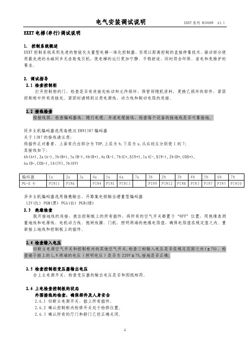
异步主机编码器选用推挽输出、开路集电极输出增量型编码器 12V(红) PGM(黑) PGA(白) PGB(绿)
FB-10 待梯门状态
FD-05 FE-00 FE-01~43 FE-32
返平层停车延时 集选方式 各楼层显示设定 电梯功能选择
电气安装调试说明
EXXT 系列 M3000N A3.1
O1 O2 12 04 3 13 1 04 05 05 按电梯实际设置 按电梯实际设置 按电梯实际设置 按电梯实际设置 按电梯实际设置 65535 65535 8448 0 0 0 2 15% 0.2O 0.6O 0.05 0(根据 UPS 设定) 0.6(调节停车) 0O(不返基站) 10 45 按电梯实际设置 按电梯实际设置 按电梯实际设置 按电梯实际设置 按电梯实际设置 0:基站正常关门 1: 基站开门等待 2:每 层开门候梯 0.9 0 详见一体机用户手册 34816
2
电气安装调试说明
EXXT 系列 M3000N A3.1
2.6.6 安全回路导通且工作可靠。
2.6.7 门锁回路导通且工作可靠。
2.6.8 井道畅通,轿厢无人,并且具备适合电梯安全运行的条件。
2.6.9 控制柜及曳引机地线接地良好。
2.6.10 外围按照厂家图纸正确接线。
2.6.11 每个开关工作正常 动作可靠。
蔽线,并且与编码器原线的连接最好用烙铁焊接
2.6.18 编码器屏蔽层要求在控制柜一端接地可靠(为免除干扰,建议单端接地)
ArcSWAT中文手册
ARCSWAT2.1 INTERFACE FOR SWAT2005
用户使用向导
M. WINCHELL,R.SRINIVASAN,M.DILUZIO,J.ARNOLD
JULY,2008
翻译制作:94527257
翻译初稿完成时间:2009 年 3 月 14 日
BLACKLAND RESEARCH CENTERTEXAS AGRICULTURAL EXPERIMENT STATION720 EAST BLACKLAND ROAD -TEMPLE, TEXAS 76502
6.1.1 启动............................................................................................................................. 29 6.1.2 Land Use 数据 ............................................................................................................ 30 6.1.3 Soil 数据 ..................................................................................................................... 34 6.1.4 Slope分类..................................................................................................................... 37 6.1.5 Landuse, Soil, And Slope的覆盖................................................................................. 39 6.2 HRU定义............................................................................................................................ 40 第七章 输入气象数据 ................................................................................................................... 44
日本新光电子秤中文说明书
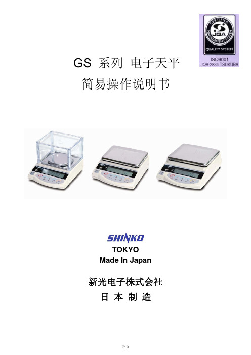
3. 安装
为确保天平发挥最佳效能, 天平要放在合适的工作环境中. 否则可能导致错误结果:
1. 勿放在松软地方, 造成天平不平衡.
2. 勿放在温度或湿度突变剧烈的地方.
3. 勿放在高温、高湿或多尘的地方.
4. 勿放在不牢固的台面, 或接近有振动的地方.
5. 勿放在风扇或冷气机的气流下的地方
6. 勿放在太阳直射的地方
设定代码详见52表格按zerotare键最右方数值会改变按数次直到显示屏显示用户需要的设定设定代码详见52表格52功能設定表格显示屏显示功能功能指令右方数值解说关闭比较测定功能比较测定功能任何时间判别包括在不稳定时判别环境高于5范围判别判别范围一个限定值判别ok或lo只在比较测定功能激活时看到判别点两个限定值判别hiok或lo关闭零位跟踪零位跟踪开动零位跟踪开动零位跟踪防止零位偏差关闭自动关机自动关机开动自动关机只限用充电池模式六数字输出接口输出七数字输出0114ct克拉15oz盎司16lb英磅17ozt全衡盎司18dwt英钱19grain1atlhongkong香港两1btlsingaporemalaysia新加坡两1ctltaiwan台湾两1dmommommes1etola20pcs件数1f百分比单位设定设定后可用功能键快速切换单位00unitset停用关闭glp打印glp打印开动glp打印只限gsw系列出厂已设定才显示显示屏显示功能功能指令右方数值解说按下打印键输出一个数据仅在稳定时输出一个数据不包括零位仅在稳定时输出一个数据包括零位当稳定时的一个输出并在不稳定时连续输出数据输出控制按下打印键输出一个数据只在稳定时4800bps波特率仅在七数字输出下使用出厂已设定切换单位天平可预先设定最多五个重量单位
7.1 一次采样 1.
按“Function”键, 使显示屏显示“Pcs”. 进入(计数)测量模式.
QSAN XEVO 2.2 软件手册说明书

XEVO 2.2 软件手册2023年四月公告版权©版权所有2023 QSAN广盛科技保留所有权利。
未经QSAN广盛科技书面许可,不得复制或传播本文档的任何部分。
QSAN认为本出版物在发布之日内容准确无误。
信息如有更改,恕不另行通知。
商标▪QSAN、QSAN标志、、XCubeFAS、XCubeSAN、XCubeNXT、XCubeNAS、XCubeDAS、XEVO、SANOS是QSAN广盛科技的商标或注册商标。
▪Microsoft、Windows、Windows Server和Hyper-V是Microsoft Corporation在美国和 / 或其他国家/地区的商标或注册商标。
▪Linux是Linus Torvalds在美国和 / 或其他国家 / 地区的商标。
▪UNIX是The Open Group在美国和其他国家 / 地区的注册商标。
▪Mac和OS X是Apple Inc. 在美国和其他国家 / 地区的注册商标。
▪Java和所有基于Java的商标和标志是Oracle和 / 或其附属公司的商标或注册商标。
▪VMware、ESXi和vSphere是VMware, Inc. 在美国和 / 或其他国家 / 地区的注册商标或商标。
▪Citrix和Xen是Citrix Systems, Inc. 在美国和 / 或其他国家 / 地区的注册商标或商标。
▪本文件中用于宣称拥有商标和名称的实体或其产品的其他商标和商品名称均为其各自所有者的财产。
目录公告 (i)注意 (viii)前言......................................................................................................................................... i x 关于本手册 (ix)相关文档 (ix)技术支持 (ix)信息、提示和注意事项 (x)约定 (xi)1.开始 (12)1.1. 寻找存储系统 (12)1.2. 初始设置 (13)2.XEVO 用户界面 (14)2.1. XEVO网页用户界面概述 (14)2.2. 访问管理USB LCM (16)3.仪表板选项 (18)3.1. 仪表板概述 (18)4.存储选项 (24)4.1. 存储信息 (24)4.2. 配置存储池 (27)4.3. 热备用硬盘 (38)4.4. 硬盘漫游 (38)4.5. SSD缓存 (39)4.6. 自动分层 (40)5.主机选项 (41)5.1. 配置主机组 (41)6.保护选项 (48)6.1. 保护功能 (48)6.2. 配置保护组 (50)7.分析选项 (63)7.1. 分析功能 (63)7.2. 阵列分析 (63)8.系统选项 (65)8.1. 阵列信息 (65)8.2. 配置系统设置 (67)8.3. 配置数据端口设置 (71)8.4. 维护 (74)8.5. 数据加密 (82)9.消息选项 (83)9.1. 日志中心 (83)9.2. 配置通知设置 (84)10.支持和其他资源 (88)10.1. 获得技术支持 (88)10.2. 文档反馈 (89)附录90最终用户许可协议 (EULA) (90)图表图表2-1 XEVO 仪表板 (14)图表 2-2 便携式USB LCM (16)图表2-3 USB LCM屏幕 (16)图表3-1 XEVO仪表板 (18)图表3-2 仪表板中的性能图表 (21)图表3-3 右上角图标 (22)图表4-1 精简资源调配存储池详细信息 (28)图表4-2 列出硬盘组 (31)图表4-3 列出存储卷 (34)图表5-1 iSCSI主机组详细信息 (42)图表5-2 光纤通道主机组详细信息 (42)图表5-3 列出主机配置文件 (44)图表5-4 列出连接的存储卷 (45)图表6-1 保护组 (50)图表6-2 具有快照计划的保护组 (52)图表6-3 列出快照任务 (52)图表6-4 快照中心 (54)图表6-5 本地复制计划保护组 (58)图表6-6 列出复制任务 (58)图表6-7 远程复制计划保护组 (60)图表6-8 列出复制任务 (61)图表7-1 性能图 (64)表格表格3-1 硬件警报窗格说明 (19)表格 4-1 一般存储参数 (24)表格4-2 厚配置存储池参数 (24)表格4-3 精简配置和自动分层存储池参数 (25)表格4-4 SSD缓存参数 (26)表格4-5 存储卷参数 (26)注意文档中包含的信息已经过审核以确保准确性。
Site Analyrer中文使用手册word精品文档19页
SITE ANALYZER™电缆和天线无线系统测试仪操作说明适用机型SA-1700EX, SA-1700EXP SA-2500EX, SA-6000EX开机对于第一次通电、发生故障后,需要重置仪器(返回到默认值,第119页)。
自检仪器在加电时执行自动自检。
如果自检失败,请参阅第126页的故障排除中可能的原因和纠正措施。
如果问题仍然存在,则返回服务站。
仪器的按键网络分析仪有两种类型的键。
第一种类型称为硬键,总对应于一个特定的功能。
键的功能不改变而且被印在仪器表面或键上。
第二类型被称为软键(功能键)。
在显示器的左侧五个按键就是软键。
每个软键具有的功能可以根据操作模式而变化。
键的功能将被在显示器的左边或下一次按键而确定。
1.功能键:激活键的右侧所描述的功能。
2.硬键Mode :启动模式菜单。
用于选择测量匹配、故障定位、测量功率或实用模式。
Config :激活当前模式下的配置菜单。
使用此设置可改变参数(如频段、距离和单位)。
Calibrate :激活校准菜单。
Marker :激活标记菜单。
用于标记的开启或关闭以及移动激活了的标记。
3.数字键输入所选择项目中的数值数据或如定义所描述的功能。
4.Esc键在菜单中:返回到上一级菜单。
在数据输入时:退出数据输入而不改变其值。
5.Enter键在列表选择时:选择列表中突出显示的项目。
在数据输入时:退出数据输入,更改该值。
6.光标键左箭头在数据输入时:每按一次删除先前输入的一个字符数据。
在标记使用中:每按一次向左移动激活的标记一个点。
其他情况:所定义的功能描述。
右箭头在标记使用中:每按一次向右移动激活的标记一个点。
其他情况:所定义的功能描述。
上箭头在数据输入时:增加数值。
在标记使用中:将标记移动到扫描线的最大值。
按对比度键后:增加显示屏的对比度。
其他情况:所定义的功能描述。
下箭头在数据输入时:减少数值。
在标记使用中:将标记移动到扫描线的最小值。
按对比度键后:减少显示屏的对比度。
EV使用手册

其它注意事项 1 —— POP3邮件客户端中 邮件客户端中使用EV
使用POP3邮件客户端不需安装EV客户端 客户端 正常邮件和已归档邮件不会通过不同的图标区别开 双击无法调取已归档邮件的原始内容,打开的仍然是快捷方式 打开的仍然是快捷方式 需要点击快捷方式中的“查看原始项”的链接来访问原始内容 的链接来访问原始内容
如何使用“搜索保管库”4 —— 高级搜索
“高级搜索”模式可以对各个具体字段进行条件的筛选 与基本搜索不同,如果您在搜索字段中输入两个或多个词语 您在搜索字段中输入两个或多个词语,则高级搜 索将返回包含任何这些词语的所有项目。例如,department department meeting 可找到包含词语“department”的所有项目以及包含词语 的所有项目以及包含词语 “meeting”的所有项目。 若要搜索包含两个或多个特定词语的所有项目,请使用加号 (+)。例如, 请使用加号 department +meeting 可找到同时包含词语“department” department”和 “meeting”的所有项目。必须在加号前输入空格。 若要从搜索中排除某个词,请使用连字符作为其前缀。例如 例如,meeting -department 可找到包含词语“meeting”但不包含“department” department” 的所有项目。 若要使用通配符进行搜索,请使用星号 (*) 查找零个或多个字符 查找零个或多个字符,使用 问号 (?) 查找任何一个字符。使用通配符之前,必须至少输入词语的前 必须至少输入词语的前 三个字符。例如,min* 可找到词语“minutes”、“minimum” minimum”等。
EV还原功能的使用 2 —— 搜索界面中的还原功能
在搜索界面中,也提供了对已归档邮件的还原功能 也提供了对已归档邮件的还原功能 使用搜索界面中的还原功能,不会把已归档邮件从快捷方式替换回原始邮件 不会把已归档邮件从快捷方式替换回原始邮件, 而是将原始邮件还原到“已还原项目集 已还原项目集”这个目录中,此目录会在还原时被 自动创建。
EVS在转播车上的应用
EVS在转播车上的应用前言EVS硬盘慢动作系统是专用于转播大型体育赛事的专业产品。
广东电视台为2008北京奥运会、2010广州亚运会等大型体育赛事的转播自主设计了18讯道高清电视转播车,该转播车网络慢动作系统配备了4台SD/HD现场及演播室制作播出服务器XT[2]、1台素材管理工作站[IP]Director和2台可移动媒体归档解决方案XFile[2] 。
如图1所示:图1,EVS专业产品一、EVS及其网络系统EVS公司从1994年起就致力于视频硬盘记录的研究,基于硬盘的慢动作重放设备在1998年法国世界杯足球赛等重大比赛中大显身手,确立了其行业地位,并且成为了相关产品的首选供应商。
EVS核心产品以及IPS集成制作系统在全球包括奥运会在内的几乎所有的体育赛事中得到了广泛的应用。
SD/HD现场及演播室制作播出服务器XT[2]可以提供最多达6个输入/输出通道,能够提供4进2出、3进3出等多种通道组合的工作模式;支持现有所有高清标准,而且可以轻松实现NTSC和PAL, 720P和 1080i之间的切换;能够满足各种直播慢动作或录像需求,图像质量也可以根据需要自行设置,高清:帧内压缩,码率20到360Mbps可选,标清:MPEG-2、I-frame、MPEG IMX、MJPEG等可选;视频输入最大6路SD/HDSDI,1.458Gbps(SMPTE 292M)/ 270Mbps(SMPTE 259),8或10比特分辨率,自动检测每一路输入完全帧同步;视频输出通道最大6路SD/HDSDI,1.458Gbps(SMPTE 292M),10比特分辨率,每通道1路下变换后的SDI 270Mbps(SMPTE 259)输出,监视输出带时码输出和通道状态信息,每路输出通道的监视输出: HD-SDI SDI/CVBS; 5块内置300GB硬盘(30h@100Mbps),专用的硬件和为硬盘提供RAID3保护,以保证其安全性,使得XT[2]拥有完美的稳定性;控制协议支持Harris VDCP、0detics、Sony BVW、Thomson XtenDD-35等;由于现场制作需要无风险系统,它还特别配备了热交换冗余备份电源;在设置有输出通道的情况下,录像和播放可以同时进行而不相互影响,保证节目录制的连续性而不会丢失任何珍贵的画面;专有的预监模式能够保证一个操作员在最短时间内做出多角度不同时间入点完美无缝切换的多角度慢动作重放。
项和形式仪V2用户手册

修改:未经Matter和Form Inc.批准对本设备进行的任何修 改均可能会使FCC授予用户的设备操作失效。
激光东西
“符合FDA激光产品性能标准,但与6月24日激光通告NO-50 的偏差除外
2007.归类于IEC60825-1:2007的1类激光产品。 “
5
箱子里面
感谢您购买Matter和Form 3D扫描仪。 包含在您的包装箱中,您会发现: 1. 一(1)件物质和形式的3D扫描仪 2. 一(1)个AC电源适配器 3. 四(4)个可互换电源适配器插头(一套4国际) 4. 一(1)个USB B电缆 5. 一(1)个首次扫描的塑料玩具 6. 一(1)个校准盒或卡和支架 7. 设置手册 8. 电子文档 扫描仪还在转盘床的中央设有一个可拆卸的插头。取下插 头可以看到一个标准的相机螺纹插座,用户可以使用它来 安装三脚架以将物体固定到位。
● 不均匀的照明会导致纹理不均匀,尤其是在将扫描 对齐在一起时。
● 明亮的阳光直接照射和清洗扫描激光器,扫描仪记 录的点数更少。
● 根本没有灯会导致数据丢失和不准确,纹理将显示 为黑色。
● 可变的照明(在扫描过程中亮度和黑暗之间波动的 照明)将影响所采集的颜色信息,使纹理看起来有 条纹。
有关更多最新的提示和技巧,请访问我们的网站。
/help
问题材料和表面
有一些激光扫描仪无法扫描的材料。由于扫描仪通过捕获 激光照射到物体表面的数据来工作,所以使激光难以看清 的任何材料都不能很好地扫描。
以下是一些您无法首先进行扫描的资料:
● 表面太亮的物体(例如金属,珠宝,镜子等)会使 激光远离物体反射或反射。这可能会导致看起来很 嘈杂的扫描。
● 重新调整或摆放接收天线。
● 增加设备和接收器之间的距离。
SWAT使用手册(中文翻译)
Soil and Water Assessment Tool User’s Manual Version 2000S.L.Neitsch, J.G.Arnold, J.R.Kiniry, R.Srinivasan, J.R.Williams, 2002Chapter 1 overview1.1 流域结构 WATERSHED CONFIGURATION✧子流域-无数量限制的HRUs(每个子流域至少有1个)-一个水塘(可选)-一块湿地(可选)✧支流/干流段(每个子流域一个)✧干流河网滞留水(围坝拦截部分)(可选)✧点源(可选)1.1.1子流域(subbasins)子流域是流域划分的第一级水平,其在流域拥有地理位置并且在空间上与其他子流域相连接。
1.1.2 水文响应单元(HRU)HRUs是子流域拥有特定土地利用/管理/土壤属性的部分,其为离散于整个子流域同一土地利用/管理/土壤属性的集合,且假定不同HRU相互之间没有干扰。
HRUs的优势在于其能提高子流域负荷预测的精度。
一般情况下,一个子流域每会有1-10个HRUs。
为了能在一个数据集组合更多的多样化信息,一般要求生成多个具有合适数量HRUs的子流域而不是少量拥有大量HRUs的子流域。
1.1.3主河道(Reach/Main Channels)水流路线、沉积物和其他经过河段的物质在theoretical documentation section7中有描述。
1.1.4 支流(Tributary Channels)辅助性水流渠道用来区分子流域产生的地表径流输入的渠系化水流。
附属水道的输入用来计算子流域径流产生到汇集的时间以及径流汇集到主河道的输移损失。
辅助性水道输入定义了子流域最长达水流路经。
对某些子流域而言,主河道可能是最长的水流路经,如果这样,辅助性水流渠道的长度就和主河道一样。
在其他子流域,辅助性河道的长度和主河道是不同的。
1.1.5池塘、湿地和水库(Ponds/Wetlands/Reservoirs)两类水体(池塘/湿地)在每个子流域都会有定义。
vestas 2mw 风机手册
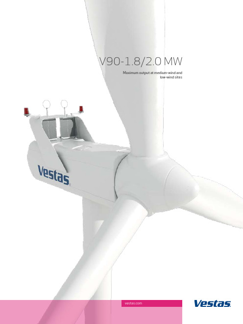
V90-1.8/2.0 MWMaximum output at medium-wind andlow-wind sitesBuilt on experienceThe V90-1.8/2.0 MW turbine is designed to deliver optimalyield in its 1.8 MW configuration at medium-wind sites (IECIIA) and in its 2.0 MW configuration at low-wind sites (IECIIIA) and builds on decades of experience with existing Vestasturbines. We started with the nacelle from the V80-2.0 MWworkhorse. Then we added the revolutionary blades used on theV90-3.0 MW high-wind turbine. Finally, all components weretuned to operate in harmony and take advantage of the specialcharacteristics of medium-wind and low-wind sites.sUperior Yield At MediUM-Wind And loW-Wind sitesDocumented high availability and production Vestas has installed more than 1,500 V90-1.8/2.0 MW turbines, since the first one was launched in 2004. If you count the entire 2 MW class, that number climbs to 5,000. All these turbines offer documented high availability and production. The V90-1.8/2.0 MW delivers low cost of energy, thanks to documented reliability and the highest yield in its class.A neW stAndArd for reliABilitY Mature technology ensures stable revenueThe many V90-1.8/2.0 MW turbines already in operation provide Vestas with invaluable knowledge on which to base further development. This means the V90-1.8/2.0 MW is built on a mature, reliable design platform, with several turbines sharing innovative, high-performance technology. The turbine features a rugged 6-gear yaw system, a proven, conventional drive train concept, a 50 Hz 4-pole generator or a 60 Hz 6-pole generator and a transformer, which is integrated with the nacelle to minimize power losses. Finally, the V90-1.8/2.0 MW is designed around a large number of standard components that several suppliers can provide, improving overall reliability and availability of the turbine.Next-generation control systemThe V90-1.8/2.0 MW is equipped with the latest turbine control and operation software VMP Global™, a state-of-the-art modular software platform developed to run the next generation of Vestas turbines. This software ensures reliable, automatic management of the V90-1.8/2.0 MW aroundthe clock. Furthermore the software supports the service organization in monitoring and troubleshooting the wind turbines on site and remotely.Innovative solutions for lubricationThe V90-1.8/2.0 MW offers a number of features that boost reliability and serviceability, including innovative solutions for lubricating key components such as the blade-bearing system and the yaw system.Safety first and easy maintenance Like all Vestas turbines, the V90-1.8/2.0 MW is designed for safe, convenient maintenance. Rotating parts are shielded, and all components are positioned to minimize service time and manpower.3x44 metres of cutting edge The revolutionary blades are made from carbon fibre and other lightweight materials. Even though V90s sweep a 27% greater area than V80s, the blade weight is almost the same. What’smore, the shape of the blades has been refined to deliver thegreatest possible output while minimizing the load on theturbine. The shape also makes these blades less sensitive todirt, providing better performance at sites affected by salt, insects or other particles in the air.Advanced grid operation and stable outputThe V90-1.8/2.0 MW is equipped with VCS™ (Vestas ConverterSystem), which ensures a constant and consistent output to thegrid. Along with the turbine’s pitch control, VCS™ also ensuresenergy optimization, low-noise operation and reduced load onthe gearbox and other key components. The turbine’s advancedgrid compliance system provides fast and powerful active andreactive power regulation to maintain grid stability as well asexcellent fault ride-through capabilities in the event of a griddisturbance. GroUndBreAKinG desiGn And eAsY MAintenAnCeCan be installed almost anywhereThe V90-1.8/2.0 MW is designed for fast, easy transportby truck, barge and rail to virtually any site in the world. The weight, height and width of all parts and main components are designed in consideration of local and international limits for standard transport. Installation, service and maintenance can be carried out using standard tools and equipment.Special optionsThe V90-1.8/2.0 MW is available with a number of special options that can be provided at the customer’s request. These options include:· Condition monitoring system· VestasOnline®, Compact or Business· Switchgear· Aviation markings on the blades· Aviation lights· Company logo· Ice detection system· Low temperature package allowing operation in temperatures as low as -30°C.innoVAtiVe teChnoloGY for QUiet And Cool operAtionCoolerTop™ saves energy and reduces sound levelsThe environmentally friendly CoolerTop™ cools the water used in the turbine’s cooling system by channeling wind into the heat exchanger. This boosts reliability, not least by reducing the number of moving parts and electrical components in the cooling system. CoolerTop™ also reduces the turbine’s own energy consumption and it keeps sound levels low.Low sound levels, high productivityThe V90-1.8/2.0 MW is a quiet turbine throughout its power curve, but it is even quieter during low-noise operation. The turbine can be operated in configurable modes that keep noise within defined sound levels, without having a significant effect on production. This makes the V90-1.8/2.0 MW ideally suited for sites where sound levels are a concern.VestAs tAKes CAre of YoUr inVestMent roUnd the CloCKVerified component lifetimeAt the Vestas Testing Centre and Technology R&D, engineering experts and technicians use state-of-the-art testing methods to ensure that the turbine meets our standards for safety, performance and reliability throughout the 20-year service life. These tests push the components beyond their specifications. One method is known as Highly Accelerated Life Testing, which is performed in a HALT chamber. Extreme fluctuationsin temperatures combined with heavy vibrations are just some of the stress tests the components are subjected to here. This enables Vestas to address design flaws before a turbine is introduced to the market.Surveillance 24/7/365Our surveillance services are manned 24/7 all year round to provide real-time surveillance, remote troubleshooting and other services. These services can also detect potential errors and disruptions before they occur, as data from your turbines is gathered and analyzed. This enables us to prepare a plan for preventative maintenance, in an effort to minimize unexpected production stops and costly downtime.Service and maintenanceVestas has service centres around the globe and we are able to cover your every need, from simple cleaning and planned maintenance to emergency call-outs and on-site inventoriescustomized for your turbines.Asset management and operation risk mitigationY our wind turbines have to be maintained with great care to avoid exposing your investment to unnecessary risks. Andthat is exactly what Active Output Management is designedto ensure – that you get the greatest possible return onyour investment in a Vestas wind turbine. AOM provides a number of advantages, such as detailed plans for serviceand maintenance, online monitoring, optimization and troubleshooting, and a competitive insurance scheme. We even offer a full availability guarantee, where Vestas pays compensation if the turbine fails to meet the agreed availability targets.Project management for effective plantsThe better your turbines fit your wind site, the more profitable your plant will be. That’s why Vestas offers to take on project management from the initial wind measurements to complete installation of the wind power plant. More than 30 years of international experience and local expertise enable us to complete:· Wind and site studies· Designing the wind power project· Selecting wind turbine types· Installing the wind farm· Servicing and maintenance throughout the turbine’s service life·Monitoring and remote troubleshooting.teChniCAl dAtA for V90-1.8/2.0 MWPower regulation pitch regulatedwith variable speedOperating data IEC IIA I EC IIIA Rated power 1,800 kW 2,000 kW Cut-in wind speed 4 m/sRated wind speed 12 m/sCut-out wind speed 25 m/sFrequency 50 Hz/60 HzOperating temperature standard range-20°C to 40°Clow temperature option-30°C to 40°CSound power(10 m above ground, hub height 80 m air density 1,225 kg/m3)4 m/s 94.4 dB(A)5 m/s 99.4 dB(A)6 m/s 102.5 dB(A)7 m/s 103.6 dB(A)> 8 m/s 104 dB(A)RotorRotor diameter 90 mSwept area 6,362 m2Nominal revolutions 14.5 rpmOperational interval 9.3 - 16.6 rpmAir brake full blade feathering with3 pitch cylindersTowerType tubular steel towerHub heights 80 m, 95 m and 105 m (IEC IIA)95 m, 105 m and 125 m (DIBt II) Generator 50 Hz 60HzType 4-pole asynchronous 6-pole asynchronouswith variable speed with variable speed Nominal output 1,800 kW/ 2,000 kW 1,800 kWGearboxType 3-stage planetary/helical Copyright NoticeThis document is created by Vestas Wind Systems A/S and contains copyrighted mate-rial, trademarks, and other proprietary information. All rights reserved. No part of the documents may be reproduced or copied in any form or by any means such as graphic, electronic, or mechanical, including photocopying, taping, or information storage and retrieval systems without the prior written permission of Vestas Wind Systems A/SAll specifications are for informational purposes and are subject to change without notice. Vestas does not make any representations or extend any warranties, expressed or implied, as to the adequacy or accuracy of this information.VCS turbines are not available in the USA or Canada.Main dimensionsBladeLength 44 mMax. chord 3.5 mWeight 6,700 kgNacelleHeight for transport 4 mHeight installed(including CoolerTop™) 5.4 mLength 10.4 mWidth 3.4 mWeight 70 metric tonnesHubMax. diameter 3.3 mMax. width 4 mLength 4.2 mWeight 18 metric tonnesTower80 mWeight 148 metric tonnes95 mWeight 206 metric tonnes105 mWeight 245 metric tonnes125 mWeight 335 metric tonnesPower curve V90-1.8/2.0 MWNoise reduced sound power modes are available.Wind speed (m/s)0 5 10 15 20 25 Output(kW)2,0001,8001,6001,4001,2001,000800600400200No. 1 in Modern EnergyThe world needs ever-greater supplies of clean, sustainable energy. Modern energy that promotes sustainable development and greater prosperity for all our planet’s inhabitants. Vestas wind turbines are already generating more than 60 million MWh of electricity every year – enough to power all of Spain,for example – and we are ready to go even further. After more than 30 years in business, Vestas continues to pioneer the wind energy business, achieving breakthroughs that transform our entire industry. Vestas Wind Systems A/S Alsvej 218940 Randers SV DenmarkTel: +45 9730 0000 Fax: +45 9730 0001vestas@6/2009-EN。
Schneider Electric TeSys GV2 Devi产品数据手册说明书
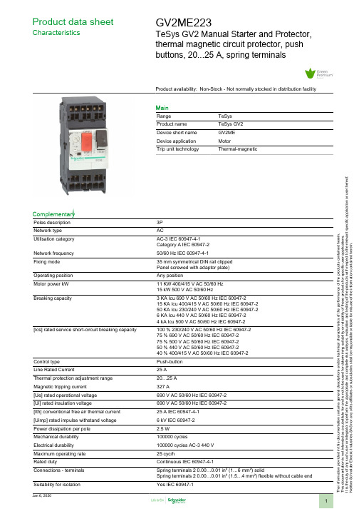
T h e i n f o r m a t i o n p r o v i d e d i n t h i s d o c u m e n t a t i o n c o n t a i n s g e n e r a l d e s c r i p t i o n s a n d /o r t e c h n i c a l c h a r a c t e r i s t i c s o f t h e p e r f o r m a n c e o f t h e p r o d u c t s c o n t a i n e d h e r e i n .T h i s d o c u m e n t a t i o n i s n o t i n t e n d e d a s a s u b s t i t u t e f o r a n d i s n o t t o b e u s e d f o r d e t e r m i n i n g s u i t a b i l i t y o r r e l i a b i l i t y o f t h e s e p r o d u c t s f o r s p e c i f i c u s e r a p p l i c a t i o n s .I t i s t h e d u t y o f a n y s u c h u s e r o r i n t e g r a t o r t o p e r f o r m t h e a p p r o p r i a t e a n d c o m p l e t e r i s k a n a l y s i s , e v a l u a t i o n a n d t e s t i n g o f t h e p r o d u c t s w i t h r e s p e c t t o t h e r e l e v a n t s p e c i f i c a p p l i c a t i o n o r u s e t h e r e o f .N e i t h e r S c h n e i d e r E l e c t r i c I n d u s t r i e s S A S n o r a n y o f i t s a f f i l i a t e s o r s u b s i d i a r i e s s h a l l b e r e s p o n s i b l e o r l i a b l e f o r m i s u s e o f t h e i n f o r m a t i o n c o n t a i n e d h e r e i n .Product data sheetCharacteristicsGV2ME223TeSys GV2 Manual Starter and Protector,thermal magnetic circuit protector, pushbuttons, 20...25 A, spring terminalsProduct availability: Non-Stock - Not normally stocked in distribution facilityMainRange TeSys Product name TeSys GV2Device short name GV2ME Device application MotorTrip unit technologyThermal-magneticComplementaryPoles description 3P Network type ACUtilisation category AC-3 IEC 60947-4-1Category A IEC 60947-2Network frequency 50/60 Hz IEC 60947-4-1Fixing mode 35 mm symmetrical DIN rail clipped Panel screwed with adaptor plate)Operating position Any positionMotor power kW 11 KW 400/415 V AC 50/60 Hz 15 kW 500 V AC 50/60 HzBreaking capacity3 KA Icu 690 V AC 50/60 Hz IEC 60947-215 KA Icu 400/415 V AC 50/60 Hz IEC 60947-250 KA Icu 230/240 V AC 50/60 Hz IEC 60947-26 KA Icu 440 V AC 50/60 Hz IEC 60947-24 kA Icu 500 V AC 50/60 Hz IEC 60947-2[Ics] rated service short-circuit breaking capacity100 % 230/240 V AC 50/60 Hz IEC 60947-275 % 690 V AC 50/60 Hz IEC 60947-275 % 500 V AC 50/60 Hz IEC 60947-250 % 440 V AC 50/60 Hz IEC 60947-240 % 400/415 V AC 50/60 Hz IEC 60947-2Control type Push-button Line Rated Current25 A Thermal protection adjustment range 20…25 A Magnetic tripping current 327 A[Ue] rated operational voltage 690 V AC 50/60 Hz IEC 60947-2[Ui] rated insulation voltage690 V AC 50/60 Hz IEC 60947-2[Ith] conventional free air thermal current 25 A IEC 60947-4-1[Uimp] rated impulse withstand voltage 6 kV IEC 60947-2Power dissipation per pole 2.5 W Mechanical durability 100000 cyclesElectrical durability 100000 cycles AC-3 440 V Maximum operating rate 25 cyc/hRated dutyContinuous IEC 60947-4-1Connections - terminals Spring terminals 2 0.00…0.01 in² (1…6 mm²) solidSpring terminals 2 0.00…0.01 in² (1.5…4 mm²) flexible without cable end Suitability for isolationYes IEC 60947-1Phase failure sensitivity Yes IEC 60947-4-1Height 3.98 in (101 mm)Width 1.77 in (45 mm)Depth 3.09 in (78.5 mm)Net weight0.62 lb(US) (0.28 kg)EnvironmentStandards EN/IEC 60947-2EN/IEC 60947-4-1CSA C22.2 No 60947-4-1UL 60947-4-1Product certifications IECEE CB SchemeULCSACCCEACATEXBVLROS (Lloyds register of shipping)DNV-GLRINAProtective treatment THIP degree of protection IP20 IEC 60529IK degree of protection IK04Ambient air temperature for operation-4…140 °F (-20…60 °C)Ambient air temperature for storage-40…176 °F (-40…80 °C)Fire resistance1760 °F (960 °C) IEC 60695-2-1Operating altitude6561.68 ft (2000 m)Ordering and shipping detailsCategory22367 - MANUAL STR PROTECTOR - GV2Discount Schedule I11GTIN00785901212225Package weight(Lbs)0.33 kg (0.73 lb(US))Returnability NoCountry of origin FROffer SustainabilitySustainable offer status Green Premium productREACh Regulation REACh DeclarationEU RoHS Directive Compliant EU RoHS DeclarationMercury free YesRoHS exemption information YesChina RoHS Regulation China RoHS DeclarationEnvironmental Disclosure Product Environmental ProfileCircularity Profile No need of specific recycling operationsWEEE The product must be disposed on European Union markets following specificwaste collection and never end up in rubbish bins.Contractual warrantyWarranty18 monthsProduct data sheetPerformance CurvesGV2ME223Thermal-Magnetic Tripping Curves for GV2ME and GV2PAverage Operating Times at 20 °C Related to Multiples of the Setting Current1 3 poles from cold state2 2 poles from cold state3 3 poles from hot stateCurrent Limitation on Short-Circuit for GV2ME and GV2P (3-Phase 400/415 V))Dynamic StressI peak = f (prospective Isc) at 1.05 Ue = 435 V1Maximum peak current224-32 A320-25 A417-23 A513-18 A69-14 A76-10 A84-6.3 A9 2.5-4 A10 1.6-2.5 A111-1.6 A12Limit of rated ultimate breaking capacity on short-circuit of GV2ME (14, 18, 23, and 25 A ratings).Thermal Limit on Short-Circuit for GV2METhermal Limit in kA2s in the Magnetic Operating ZoneSum of I2dt = f (prospective Isc) at 1.05 Ue = 435 V124-32 A 220-25 A 317-23 A 413-18 A 59-14 A 66-10 A 74-6.3 A8 2.5-4 A9 1.6-2.5 A 101-1.6 AProduct data sheetDimensions DrawingsGV2ME223DimensionGV2ME(1)MaximumMountingGV2ME On 35 mm railc = 78.5 on AM1 DP200 (35 x 7.5)c = 86 on AM1 DE200, ED200 (35 x 15)On panel with adapter plate GV2AF02On pre-slotted plate AM1 PAOn rails DZ5 MB201GV2AF01Combination GV2ME + TeSys k contactorGV2AF3Combination GV2ME + TeSys d contactorGV2AF4 + LAD311Combination GV2ME + TeSys d contactorGV2ME + GV1L3 (Current Limiter)X1 = 10 mm for Ue = 230 V or 30 mm for 230 V < Ue ≤ 690 VProduct data sheetGV2ME223 Connections and SchemaGV2ME•• and GV2RTConnection of Undervoltage Trip for Dangerous Machines (Conforming to INRS) on GV2ME Only。
CA公司光伏I-V曲线测试仪用户手册说明书

1. 警告您刚刚购买了法国CA公司的I-V TRACER FTV200 光伏I-V曲线测试仪,我们非常感谢您对我司产品的信任!请在使用仪器前仔细阅读以下说明。
遵守安全保护措施。
仪器中符号的意义如下:注意,危险!请查阅用户手册。
CE标志确保仪器符合欧洲标准。
仪器完全受双重绝缘或加强绝缘的保护。
垃圾桶上打叉的符号意思是,根据WEEE指令2002/96/EC,该产品的电子配件在废弃时必须进行回收再利用。
USB接口。
警告!测试点适配器使用:当您连接测试点时,请核实并确保装置或电路上不带电。
应该无导电部分外露。
连接测试点至装置或电路,仅与以下列出的测试附件相连:导电部分2. 安全保护措施为了正确使用仪器,以下的防护措施是强制性的。
不遵守以下指示,可能导致触电、爆炸、火灾等危险。
的意思为,警告!使用配件前请阅读说明。
说明前加上这个标志,未按解释执行,可能导致人身事故或配件和设备的损坏。
如果不正确地使用仪器,安全性将不能保证,可能导致危险的测试环境。
用户不可自行更换内部的可充电电池。
需要更换内部电池,请联系法国CA在华子公司。
任何系统连接本仪器的安全性责任,由接入系统之人承担。
为了您的安全,请仅使用仪器附带的导线和配件:它们符合IEC 61010-031(2002)的标准。
当传感器或配件低于仪器的安全等级,降额必须应用于整个设备。
每次使用前,确保导线、接线盒及配件完全符合工作条件。
每个绝缘受损的(哪怕是局部的)导线、传感器或配件,都必须送修或是报废。
进行测量时请不要使用主电源供电。
主电源仅用于为内部电池充电,仅在仪器关闭时进行充电。
遵守使用环境。
个人防护设备的使用与仪器使用环境的推荐防护设备一致。
仪器能使用于CAT III 600V 或CAT II 1000V的设备。
请勿使用于电压或安全等级更高的系统。
要更换内部电池,请仅联系法国CA在华子公司。
这些部件有特殊的安全防护装置,使用非原配的备件可能导致严重的人员或设备的损伤事故。
r2v使用说明

R2V用户使用说明简介Raster2Vector 3.x(R2V)Raster2Vector 3.x(R2V)for Windows95/NT是一种高级光栅图矢量化软件系统。
该软件系统将强有力的智能自动数字化技术与方便易用的菜单驱动图形用户界面有机地结合到Windows & NT环境中,为用户提供了全面的自动化光栅图像到矢量图形的转换,它可以处理多种格式的光栅(扫描)图像,是一个可以用扫描光栅图像为背景的矢量编辑工具。
由于该软件的良好的适应性和高精确度,其非常适合于GIS、地形图、CAD及科学计算等应用。
R2V提供简便及完整的将光栅图像数字化为矢量数据的解决方案,这些光栅图像可以是扫描的图纸、航摄照片或是卫星图片。
整个的光栅图像矢量化过程可以是全自动的且不需要人工干预(也可选人工干预)。
你仅需要将扫描图像显示在屏幕上并选择矢量化命令,所有的线段在数秒钟即可识别出来并显示在图像上供你校正与编辑。
强大的编辑及处理功能可用于矢量的编辑、大地坐标校正及高程数据标注。
拥有R2V,你可以忘掉缓慢而又不准确的数字化仪人工手动跟踪描绘。
你可以在草稿纸上画草图,你只需扫描你的图纸,然后让R2V高精度地自动或半自动矢量化它们。
一张典型的地形图或区划地图,通常以200DPI的黑白或灰度扫描,在Pentium级PC上数秒内即可完成矢量化。
你可以在同一个显示窗口下处理各种类型的数据,这些数据包括线、点、多边形、文本标注、光栅点以及控制点。
使用R2V,你就可以自动地矢量化地图及其他图纸,快速智能地完成航片或卫片的数字化及地理解析工作,用最新的航摄照片或其他图像更新你现存的矢量数据集。
R2V for Windows & NT非常易于使用,其基本的转换和编辑功能,拥有不同技术背景的用户都可快速掌握。
运行环境系统最低需求操作系统:R2V 32位版本需要Windows 95或Windows NT才能运行。
CPU:486或更好RAM:8MB(建议32MB以上)硬盘容量:安装软件需要2MB,更多的空间用于存储你的扫描图像及矢量化数据显示设备:8位256色或更好的SVGA兼容显示卡R2V主要特点图像格式:支持1位黑白、8位灰度及彩色(4位、8位及24位)的TIFF、GeoTIFF和BMP图像文件格式。
Evs的操作与基本设置

Evs的操作与基本设置一、EVS系统概述EVS是产自EVS Broadcast Equipment comp.的慢动作回放视频系统,河南电视台EVS系统是由2台视频及媒体服务器XT3、2台慢动作控制单元Multicam LSM及周边附件组成。
XT3服务器可以实现最高6通道3D/1080p配置,速度和可靠性在目前都居世界前列,拥有超强的功能和表现力。
它的特点及优势可以总结为以下几点:1. 循环录制功能:可实现最多30小时不间断节目录制。
2. 无须改变硬件配置,可以实现多种编码格式的录制,操作简单便捷。
3. 混合网络系统:目前河南台的EVS系统有2种网络设置:SDTI网和千兆网。
SDTI网络设置相对简单,通过2台主机后端的视频接口环接就可以实现2台主机资源的随时调用。
千兆网络通过在八讯道电脑上安装软件,实现从上载到播出的全面媒体控制解决方案,缺点是兼容格式有限,目前非线只支持DVCPRO 1080i的高清格式。
4. 录制和播出通道可以灵活设置。
慢动作控制单元Multicam LSM(如图2)面板小巧,按键少而精,非常便于操作员快速调用和操作,下面会在《操作说明》部分对其详细介绍。
二、基本概念在开始介绍EVS的具体操作之前,先要介绍EVS中片段存储非常重要的概念:片段的分级存储。
这是操作员知道自己所建的clip片段存在哪里、如何调用的关键。
在EVS中,clips片段采取分级存储的方式,如图3所示。
以在4进2出模式下建clip片段来举例说明:打好in点out点建立一个clip,存在F1中,这时F1里共有4个机位相同时长的4个clips存储,F1—F10共可存储clips40个,都存在clip numbers 这一级目录中;向上一个目录,就是clip banks目录,每个clip bank 下有F1—F10十个按键,其中F1—F9为clips存储目录,F10为PLs播表存储目录。
也就是说,在这级目录中,共可存储40×9=360个clips,还可存储10个pl播表;最高级目录为pages目录,通过page + F1--F10键可直接调用,每一个page有10个bank,依次类推,在4进2出模式下,共可存储360×10=3600个clips,100个pl播表(在主机设置时,pl值通常被设为99个)。
(完整版)汉光专利信息分析系统用户使用手册.
目录第一章功能概述 (11.1功能概要 (11.2适用范围 (11.3名词语术 (1第二章功能运行环境 (22.1硬件环境 (22.2软件环境 (22.3数据库环境 (22.4数据库安装 (2第三章《汉之光华专利情报分析系统2.0》安装说明及服务器配置.7第四章系统维护功能说明 (94.1用户管理功能 (94.2数据库更新功能 (104.3建立数据库索引功能 (104.4数据库初始化功能 (11第五章专题建立功能说明 (12第六章专题维护功能说明 (146.1专题更名 (146.2专题删除 (156.3内容更新 (166.4专题转换 (176.5专题合并 (18第七章数据加工功能说明 (20 7.1分类删除 (207.2检索删除 (227.3逐项删除 (237.4日期修正 (247.5申请人合并 (267.6发明人合并 (28第八章专题分析功能说明 (29 8.1宏观分析 (298.1.1 构成分析 (298.1.2 趋势分析 (328.1.3 技术道路 (348.1.4 排名分析 (358.1.5 增长率分析 (378.1.6 同族专利 (398.1.7 人力投入 (418.2微观分析 (438.2.1 手工标引 (438.2.2 IPC修正 (458.2.3 申请人修正 (468.2.4 结果修正 (498.2.5 聚类修正 (518.2.6 自动标引 (538.2.7 矩阵分析 (558.2.8 技术分类分析 (588.2.9 申请人分析 (59第一章功能概述1.1 功能概要《汉之光华专利情报分析系统2.0》——是利用计算机信息技术,对用户关心的专题专利情报进行统计分析,深层次地挖掘专利情报中包含的技术、经济、法律情报,为科研开发、专利战略决策提供依据。
1.2 适用范围9本产品适用于各级技术生产企业。
9中介咨询机构。
如:专利事务所,律师事务所等单位。
9大专院校、科研机构的图书馆、电子信息部门。
维格汗摄像头操作手册说明书

Operation ManualTable of Contents1 Introduction (1)2 Cameras (2)2.1 Available Models (2)2.2 Basic Parameters (2)2.3 Wiegand Interface Appearance (3)3 Transfer Access Control Card No. via Wiegand Protocol (4)3.1 Transfer Access Control Card No. via 26-Bit Wiegand Protocol (4)3.1.1 Advantage (4)3.1.2 Applicable Wiegand Protocol (4)3.1.3 Card No. Encoding Mode (4)3.1.4 Use Wiegand Protocol to Transfer Card No (4)3.1.5 Configure Parameters (6)3.2 Transfer Access Control Card No. via Hik 34-Bit Wiegand Protocol (8)3.2.1 Advantage (8)3.2.2 Applicable Wiegand Protocol (8)3.2.3 Use Wiegand Protocol to Transfer Card No (8)3.2.4 Configure Parameters (10)4 Transfer Plate Number via Wiegand Interface (11)4.1 Overview (11)4.2 Advantage (11)4.3 Applicable Wiegand Protocol (11)4.4 Plate Number Encoding Mode (11)4.5 Configure Parameters (12)5 Appendix (13)5.1 Paxton Configuration (13)5.1.1 Connect Net2 ACU (13)5.1.2 View ANPR Captured Image in Net2 (15)5.2 FTP Server Creation (17)1IntroductionThis manual is about the Wiegand configuration and features of network cameras. The manual is created as a guide for the technical support engineer, sales engineer, etc. Currently overseas license plate cameras support 3 Wiegand protocols: Card ID 26-bit Wiegand protocol, Hik 34-bit Wiegand protocol, and SHA-1 26-bit Wiegand protocol (European access control manufacturers Paxton and Salto use the 26-bit Wiegand protocol). The various protocols are explained as follows.2Cameras2.1Available ModelsThe available models of network cameras are:DS-2CD7A26G0/P-IZHSWG (2.8-12 mm)DS-2CD7A26G0/P-IZHSWG (8-32 mm)2.2Basic ParametersImage sensor 1/1.8"Progressive Scan CMOSMax. resolution 1920 × 1080 @60 fpsIllumination 0.002 Lux @ (F1.2, AGC ON) , 0 Lux with IR Iris AutoWDR 140 dBShutter Speed 1 s to 1/100,000 sProtection level IP67 IK10Supplement light IR Light/White LightANPR technology Supported2.3Wiegand Interface AppearanceFigure 2-1Wiegand InterfaceConnection:Connect the block’s D0, D1 and GND to those of receiving terminal accordingly.3Transfer Access Control Card No. via Wiegand Protocol3.1Transfer Access Control Card No. via 26-Bit Wiegand ProtocolMap the license plate number with the access control card number.Find the related card number in black and white list, and transfer the card information (26 bit) via Wiegand interface.Determine whether the car has permission to pass according to the card number. 3.1.1Advantage1. Theoretically compatible with any standard access control system2. Realize access control to cars.3.1.2Applicable Wiegand Protocol26-bit Wiegand Protocol3.1.3Card No. Encoding ModeFigure 3-1Card No. Encoding Mode3.1.4Use Wiegand Protocol to Transfer Card No.Information Description:●The front parity bit is the even parity bit of the binary format of the first12 bits of the combination of card ID and site code.●The rear parity bit is the odd parity bit of the binary format of the last 12bits of the combination of card ID and site code.The front parity bit (even parity bit)8-bit(To express the sitecode ID, if the sitecode ID is less than8 digits, 0 will beadded before the IDuntil it is 8-digitnumber.)16-bit(To express the cardID, if the card ID isless than 8 digits, 0will be added beforethe ID until it is16-digit number.)The rearparity bit(odd paritybit)Coding Process:1.Card number is made up of card ID and site code.2.Convert card ID A to binary format, as C.3.Covert site code B to binary format, as D.4.The combination of site data and card data is D + C.5.The front parity bit is the even parity bit of the first half of D + C.6.The rear parity bit is the odd parity bit of the second half of D +C.7.The return result: front parity bit + D + C + rear parity bit.Note the order of the combination of site data and card data is D + C.Example:Card number: 12345 011The coding process are show as below.●Split the card number as the card ID (12345) and site code (011).●Convert 12345 to binary format, as: 0011000000111001.●Convert 011 to binary format, as: 00001011.●Site data and card data as: 00001011 0011000000111001●Bit 1 is an even parity bit for the following 12 bits (bit 2 to bit 13), as 1.●Bit 26 is an odd parity bit for the previous 12 bits (bit 14 to bit 25), as 1.●According to the converting mode(Even parity bit + site data + card data +odd parity bit), you can get a binary code as: 1 000010110011000000111001 1.3.1.5Configure ParametersSet Wiegand Type as Card IDSteps1. Go to Configuration->Road Traffic->Wiegand-> Wiegand Type.Figure 3-2Wiegand Configuration InterfaceEnable Vehicle DetectionSteps:1. Go to Configuration->Road Traffic->Detection Configuration.2. Check the checkbox of Enable to enable Vehicle Detection.3. Set the specific detection parameters, which are the same as those of conventional ANPR cameras.Figure 3-3Detection Configuration InterfaceConfigure Blocklist & AllowlistSteps:1. Go to Configuration->Road Traffic->Blocklist & Allowlist.2. Click Export to download Blocklist & Allowlist template.3. Fill in the template.Figure 3-4Blocklist & Allowlist Excel TemplateYou can set at most 10000 license plates in allowlist and blocklist in total.You should enter 8-digit Card ID in the ID row. Otherwise, unknown error may occur. If you enter Card ID more than 8 digits, the last 8 digits will be kept. 9 8984 2118 in the 7th line will be saved as 8984 2118.If you enter Card ID less than 8 digits, 0 will be added before the ID until it is 8-digit number. For example, 984 2119 in the 8th line will be saved as 0984 2119.If you accidently enter the same plate number in the template, the bigger No. will take effect.Update Blocklist & Allowlist ManuallySteps:1. Go to Configuration->Road Traffic-> Blocklist & Allowlist.2. Click Browse to select the file you have finished.3. Click Import to upload the list.Figure 3-5Blocklist & Allowlist Importing Interface3.2Transfer Access Control Card No. via Hik 34-Bit Wiegand ProtocolMap the license plate number with the access control card number.Find the related card number in black and white list, and transfer the card information (34 bit) via Wiegand interface.Determine whether the car has permission to pass according to the card number.The protocol for directly transferring the access control card No. through the Wiegand interface is a private protocol of Hikvision.3.2.1Advantage1. Theoretically compatible with any standard access control system2. Realize access control to cars.3.2.2Applicable Wiegand Protocol34-bit Wiegand Hikvision Private Protocol3.2.3Use Wiegand Protocol to Transfer Card No.Information Description:●The return result (even parity bit + card data +odd parity bit) will be sent toHikvision access control device supporting Wiegand protocol.●The front parity bit is the even parity bit of the first 16 bits of the cardnumber.●The rear parity bit is the odd parity bit of the last 16 bits of the card number.Support up to 10-digit card number. If you enter a card number of more than 10 digits, only the first 10 digits are kept. Currently, the maximum supported card number is 2147483647 because of the limitation of the platform int length type.The front parity bit (even parity bit)32-bit(To express the cardID, if the card ID ismore than 10 digits,the first 10 digits willbe applied.)The last paritybit (odd paritybit)Coding Process:1.Convert card number A to hexadecimal format, as B.2.Covert number B to binary format, as C.3.The front parity bit is the even parity bit of the first half of C.4.The rear parity bit is the odd parity bit of the second half of C.5.The return result: front parity bit + C + rear parity bit.Example:Card number:1234567890The coding process are show as below.●Convert 1234567890 to hexadecimal format, as: 0x49 0x96 0x02 0xD2.●Convert 0x49 0x96 0x02 0xD2 to binary format, as: 0100 1001 1001 01100000 0010 1101 0010.●Bit 1 is an even parity bit for the following 16 bits (bit 2 to bit 17), as 1.●Bit 34 is an odd parity bit for the previous 16 bits (bit 18 to bit 33), as 0.●According to the converting mode(even parity bit + card data + odd paritybit), you can get a binary code as: 1 0100 1001 1001 0110 0000 0010 11010010 03.2.4Configure ParametersSet Wiegand Type as Card IDSteps1. Go to Configuration->Road Traffic->Wiegand-> Wiegand Type.Figure 3-6Wiegand Configuration InterfaceFor the steps to enable Vehicle Detection and Blocklist and Allowlist Configuration, see 3.1.5 Configure Parameters.4 Transfer Plate Number via Wiegand Interface4.1 OverviewThe Wiegand interface directly transmits the license plate number, and performs a hash operation on the license plate number. The last 24 bits are taken through the Wiegand standard interface, and an even parity bit and an odd parity bit are added before and after the 24 bits respectively according to the standard 26 bit protocol. The result will be sent to Wiegand access control (third parties like Paxton or Salto) equipment.4.2 AdvantageCompatible directly with access control system and platform of Paxton in the UK and Salto in Europe.4.3 Applicable Wiegand Protocol26-bit Wiegand Protocol4.4 Plate Number Encoding Mode Figure 4-1 Wiegand Protocol Flow ChartHere we take plate number 2180870 as example.⏹ The 24 bit encoded by SHA1 mode is 0x54 0x52 0x22⏹ Add parity bit based on 3.1.4 Use Wiegand Protocol to Transfer CardNo.Plate Number Add parity bit SHA1 Keep last 24bitSendAdd parity bit to 26 bit both before and after the number based on 26 bit protocol4.5Configure ParametersSet the Wiegand Type as Paxton.Steps:1. Go to Configuration->Road Traffic->Wiegand ->Wiegand Type.Figure 4-2External Device Settings Interface5Appendix5.1Paxton Configuration5.1.1Connect Net2 ACUSteps1.The connections for the ANPR Camera and Reader port using a Belden readercable (as per Paxton specification) on the Net2 ACU are as follows:Blue wire: D1 at ANPR – Clock/D1 on Net2 ACU Reader Port.Yellow wire: D0 at ANPR – Data/D0 on Net2 ACU Reader Port.Black wire: GND at ANPR – 0v on Net2 ACU Reader Port.2.In the door settings for the ACU that will be connected to the ANPR camera, setthe door up as follows and apply:3.In the user record, select the ‘Tokens’ tab and select ‘New Token’ to open the ‘Addnew token’ window:4.Select Vehicle number plate and enter the license plate number you wish to addfor the user; e.g. BR07 UMM5.Click OK then Apply.6.As the license plate is read by the ANPR camera, it will send the converted tokennumber to the Net2 ACU.5.1.2View ANPR Captured Image in Net2Hikvision has a second integration with Net2 that allows users to view DVR/NVR video from within the Net2 UI. This integration can be used in conjunction with the ANPR camera to show the capture of the licence plate as it is read by the camera.Steps1.Download the plugin from here: ftp://Hik_Paxton:************************.com2.Once installed, in Net2 go to Options>Camera Integration>Add, and selectHikvision DVR System from the list of camera servers.3.Add the DVR credentials to authenticate and detect the associated cameras:4.Click OK, then go to the ACU that is associated with the ANPR camera and select itas the camera that is monitoring the door.5.As the ANPR camera generates events in Net2, a camera icon will appear next tothe event. Clicking the icon will show the video associated with the ANPR event.5.2FTP Server CreationStepse FTP server tool to create the FTP server in your PC.2.Set the permission information like user name and password in the server.3.Set the path for the communication between the terminal and the server.4.Keep the software turned on.5.Put the blocklist and allowlist to be updated in the appointed directory in theserver.。
- 1、下载文档前请自行甄别文档内容的完整性,平台不提供额外的编辑、内容补充、找答案等附加服务。
- 2、"仅部分预览"的文档,不可在线预览部分如存在完整性等问题,可反馈申请退款(可完整预览的文档不适用该条件!)。
- 3、如文档侵犯您的权益,请联系客服反馈,我们会尽快为您处理(人工客服工作时间:9:00-18:30)。
MARK
RECORD RETURN
PRV CTL PAGE
播放 进入 XNET 菜单。 (连接到在网络上的其他服务器) 回到前一个 cue 标记点 用 F 键来输入时间码进入对应的记录轨迹上 用于加快 JOG 的速度,手动搜索标记点。这 种模式在接受到 PLAY/LIVE 命令后会自动重置 标记一个可用的标记点。 (256 个点循环标记) 启动 E2E 模式(即:现场模式) 在一个片段中,若这个片段仍然存在,允许操 作人员返回到记录轨迹上的相同画面 进入或者退出欲览模式 从 1 到 10 选择当前的片段页面
提供进入二级菜单的途径。当有信息需要确认时,可以
做为撤消用。
注意:SHIFT+MENU 返回主菜单,即 MAIN Menu。
SHIFT
用于切换每个键的第二级功能。
注意:即使松开这个按键上档功能仍然存在,直到其它按键被点击。
F1 F10
-
存储和回调片段,回调播放列表和进入时间码设置。
CLEAR ENTER
当开启 EVS 主界面时,首先是 PC 登陆序列,同时 EVS 软件开始 启动。倘若有一个默认的应用程序在这之前选定,这个应用程序将在 无按键点击几秒后自动运行。假如没有定义默认的应用程序或被空格 键击打,系统将仍然处在 EVS 的主菜单,并等待操作人员的下一个指 令。
题目栏
配置窗口
信息窗口
EVS 00.14.11
││SD Mon Out Mon
│
║09 LSM 4CAM (FX)
▒║ │2 COHX HD Genlock
││Audio ON
│
║10 Super LSM (CUT) ▒║ │1 MTPC Rev A1/R2
││
│
║11 Super LSM (FX) ▒║ ├ Software Releases ───────┤├ Ref & Phase ───────────┤
│
║02 LSM 1CAM (FX)
▒║ │ Audio In/Out
ห้องสมุดไป่ตู้
││Net Number 1
│
║03 LSM 2CAM (CUT) ▒║ │ 16 XLR A
││Type
Server
│
║04 LSM 2CAM (FX)
▒║ │6
││DB Size 16000 clips │
║05 LSM 3CAM (CUT) ▒║ │ #Video Ch 6
││TC in 16:36:35;27 NTSC │
║
▼║ │
││Phase:0 half pixel │
╚══════════════════════╝ └──────────────────────────┘└────────────────────────┘
┌ Messages ───────────────────────────────────────────────────────────────────┐
│├ Video & Audio ─────────┤
║06 LSM 3CAM (FX)
▒║ │5 COHX HD
││Std 1080i 59.94 NTSC │
║07 Triple LSM ) ▒║ │4 COHX HD
││Aspect Ratio 4:3 L Box │
║08 LSM 4CAM (CUT) ■║ │3
LEVER
用于启动当前的播放列表 这 项 功 能 是 将 主 输 出 ( PGM1 ) 记 录 到 MULTICAM 第一路的输入(CAMA)上,这项功 能不适合用于高清系统中 浏览片段播表和标记点 在播放列表管理中插入片段到播放列表 在当前的位置来标记一个入点 返回到定义的标记入点 在当前的位置来标记一个出点 返回到定义的标记出点 PGM+PRV 模式中:在 PGM 和 PRV 通道中切
普通模式:
这种模式中,LEVER 运行从 0%到 100%。
二级行程:
在二级行程中用来播放的素材从可从-100%到 100%或从-200%到 200% (设置菜单中 page 5- F4 ) 在控制器单元(RCU)中按下 SHIFT+LEVER 可进入二级行程。
注意:当 SD SUPER MOTION 素材在主频道登陆启动后,LEVER 一步 可达 33%。而若是 SH SUPER MOTION 素材的话,一步可达 50%。
Aud.Met.
Mix.
Sw to IN
Search
Pref
MENU
SECONDARY MENU
+
SHIFT
Rst Cam Cam A
A
Local Cam B
B
Sync Prv Cam C
C
2nd Ctrl Cam D
D
OPERATIONAL MENU
当按下 SHIFT 按键后,可进入二级功能。 LCD 可显示两个菜单。 按下 MENU 后可进入二级菜单。二级菜单用来定义一些不需要日常改 动的设置,只有返回到 SETUP 菜单才能进行修改。 再次按下 MENU 按键,可返回到操作菜单。 按下 SHIFT+MENU 将返回到 MAIN 菜单。
2
EVS MULTICAM 中文应用基础手册
EVS Broadcast Equipment SA – Dec 2005
1. 软件选择
应用程序窗口
EVS 软件可以用来进行配置和维护操作。因为 EVS 硬盘录象机可 以运行不同标准的配置和用户定义的配置能力,它也可以用于选择哪 一个配置来运行(LSM1CAM,LSM3CAM,LSM4CAM,TRIPLE LSM, SLSM,SLSM+1CAM,等等)。
多功能按键
2. 软按键: 3. LEVER:
用来对 LCD 显示并允许操作人员进入 MULTICAM 菜单进行系统设置
用于启动慢动作和播放列表的重放
4. JOG DIAL:
用于精确搜索标记在硬盘上的内容
5. Operational block 1:
PLST LOOP
BROWSE INSERT IN GOTO IN OUT GOTO OUT TAKE
片段与播放列表管理功能允许操作人员在硬盘上保留 4000 个片 段,当然这些片段也可以进行全部或部分回放。一个播放列表是由一 些带有视频和音频转换效果的片段列表所构成(播放列表最多可以定 义 90 个)。
The XNET 选项使 LSM-XT 系列服务器构成了一个整合制作环境的网络 系统。在网络上的任意一台 LSM-XT 服务器中记录的片段和素材都可被 其他控制器进行即时性的编辑或播放。
注意 : JOG DIAL 也可用于 : - 在 SETUP 菜单中设置参数。在 SETUP 菜单部分会有更加详细的介绍。
- 用于在片段数据库中对标记点以及当前播放列表的浏览。
系统处于 PLAY 或 RECORD 状态中时,JOG DIAL 随时处于可用状态
LEVER
LEVER 用于启动一个播放或修改慢动作的速度。它可运行于两个 定义不同的模式中。
║12 Super LSM+1CAM ▒║ │LSM:07.00.37
││Ref Type SD Black Burst │
║13 Super LSM+2CAM ▒║ │HCT: 27.56, 23/05/05
││Sync Mode Studio Mode │
║
▒║ │
││Genlock Ok
│
║
▒║ │
机密文档
2
3
4 4 6 6 7 8 8
9
11 11 12
28 28
32 37 38
39 39 39 39 39
41 41
44 44 44
1
Version 8.00
EVS MULTICAM - User’s Manual
EVS Broadcast Equipment SA – Dec 2005
概述
这本手册的用途是让操作人员对使用 MULTICAM 软件的 EVS 的高 清的和标清的 LSM-XT 系列服务器以及控制面板更加熟悉,从而可以快 速高效的对基础操作进行掌握。
7. LCD Display: 显示当前系统的状态
5
Version 8.00
EVS MULTICAM - User’s Manual
EVS Broadcast Equipment SA – Dec 2005
LED 颜色
选择后的按键亮红灯 按键亮绿灯时,意味着目前这个按键正具有某种功能。
例如: F1 到 F0
CLEAR 是一个多功能按键,用来删除片段、播放列表和 标记的入、出点。
用于在当前播表的末尾添加片段,同时用于确认其它功 能和信息。
6
EVS MULTICAM 中文应用基础手册
EVS Broadcast Equipment SA – Dec 2005
软按键
软按键分为上下两部分,用来区分:主功能和二级功能
在播放列表模式中,LEVER 也可用于调整速度,类型效果和持续 时间效果。
换摄象机画面 MULTI-PGM 模式中:在 PGM 选择模式和摄
象机选择模式之间进行交替选择 播放列表编辑模式中:将一个已经载入到
PRV 通道的片段插入到当前的播表中 可改变推子的行程到第二模式(参照设置菜单 的进程选择)
6. Operational block 2 :
PLAY NETWORK
分屏选项(水平或垂直)可以在节目主输出通道中同时并排显示 两个同步动作。
绘图选项可以在记录的画面上绘画和涂抹。可以使用不同颜色的 圆圈,箭头和直线对运动画面进行分析。