RJZ-3.324D中文资料
ZPD3.3中文资料
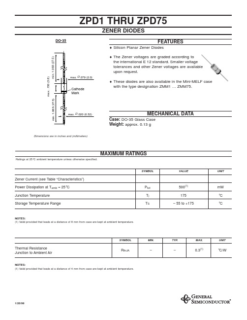
ZPD1 THRU ZPD75ELECTRICAL CHARACTERISTICS Ratings at 25°C ambient temperature unless otherwise specified.Type Zener Voltage(1)atI Z= 5 mAV Z(V)atI Z= 5 mAf = 1 kHzr zj(Ω)atI Z= 1 mAf = 1 kHzr zj(Ω)Temp. Coeff.of Zener VoltageatI Z= 5 mAαvz(10–4/K)ReverseVoltageatI R= 100 nAV R(V)atT amb= 45°CI Z(mA)atT amb= 25°CI Z(mA)Dynamic Resistance AdmissibleZener current(2)ZPD1(3)0.7 ... 0.8 6.5 (< 8)< 50–26 ... –23–280340 ZPD2.7 2.5 ... 2.975 (< 83)< 500–9 ... –4–135160 ZPD3 2.8 ... 3.280 (< 95)< 500–9 ... –3–117140 ZPD3.3 3.1 ... 3.580 (< 95)< 500–8 ... –3–109130 ZPD3.6 3.4 ... 3.880 (< 95)< 500–8 ... –3–101120 ZPD3.9 3.7 ... 4.180 (< 95)< 500–7 ... –3–92110 ZPD4.3 4.0 ... 4.680 (< 95)< 500–6 ... –1–85100 ZPD4.7 4.4 ... 5.070 (< 78)< 500–5 ... +2–7690 ZPD5.1 4.8 ... 5.430 (< 60)< 480–3 ... +4> 0.86780 ZPD5.6 5.2 ... 6.010 (< 40)< 400–2 ... +6> 15970 ZPD6.2 5.8 ... 6.6 4.8 (< 10)< 200–1 ... +7> 25464 ZPD6.8 6.4 ... 7.2 4.5 (< 8)< 150+2 ... +7> 34958 ZPD7.57.0 ... 7.9 4 (< 7)< 50+3 ... +7> 54453 ZPD8.27.7 ... 8.7 4.5 (< 7)< 50+4 ... +7> 64047 ZPD9.18.5 ... 9.6 4.8 (< 10)< 50+5 ... +8> 73643 ZPD109.4 ... 10.6 5.2 (< 15)< 70+5 ... +8> 7.53340 ZPD1110.4 ... 11.6 6 (< 20)< 70+5 ... +9> 8.53036 ZPD1211.4 ... 12.77 (< 20)< 90+6 ... +9> 92832 ZPD1312.4 ... 14.19 (< 25)< 110+7 ... +9> 102529 ZPD1513.8 ... 15.611 (< 30)< 110+7 ... +9> 112327 ZPD1615.3 ... 17.113 (< 40)< 170+8 ... +9.5> 122024 ZPD1816.8 ... 19.118 (< 50)< 170+8 ... +9.5> 141821 ZPD2018.8 ... 21.220 (< 50)< 220+8 ... +10> 151720 ZPD2220.8 ... 23.325 (< 55)< 220+8 ... +10> 171618 ZPD2422.8 ... 25.628 (< 80)< 220+8 ... +10> 181316 ZPD2725.1 ... 28.930 (< 80)< 250+8 ... +10> 201214 ZPD3028 ... 3235 (< 80)< 250+8 ... +10> 22.51013 ZPD3331 ... 3540 (< 80)< 250+8 ... +10> 25912 ZPD3634 ... 3840 (< 90)< 250+8 ... +10> 27911 ZPD3937 ... 4150 (< 90)< 300+10 ... +12> 29810 ZPD4340 ... 4660 (< 100)< 700+10 ... +12> 3279.2 ZPD4744 ... 5070 (< 100)< 750+10 ... +12> 3568.5 ZPD5148 ... 5470 (< 100)< 750+10 ... +12> 3867.8 ZPD5652.0 … 60.0(4)< 135(4)< 1000(5)typ. +10(4)–––ZPD6258.0 … 66.0(4)< 150(4)< 1000(5)typ. +10(4)–––ZPD6864.0 … 72.0(4)< 200(4)< 1000(5)typ. +10(4)–––ZPD7570.0 … 79.0(4)< 250(4)< 1500(5)typ. +10(4)–––NOTES:(1) Tested with pulses t p= 5 ms(2) Valid provided that leads at a distance of 4 mm from case are kept at ambient temperature(3) The ZPD1 is a silicon diode operated in forward direction. Hence, the subscript of all parameters should be “F” instead of “Z”.Connect the cathode terminal to the negative pole(4) at I Z= 2.5 mA(5) at I Z= 0.5 mA。
直拉法单晶硅制备虚拟仿真实验软件说明书
直拉法单晶硅制备虚拟仿真实验软件说明书北京欧倍尔软件技术开发有限公司2020年8月第一章软件简介1.1 概述本软件是材料与能源学科交叉的教育信息化建设项目,旨在为本科院校新能源材料与器件、新能源科学与工程、先进材料成形、电子信息技术等相关专业的学生提供一个三维的、高仿真度的、高交互操作的、全程参与式的、可提供实时信息反馈与操作指导的、虚拟的直拉法单晶硅制备模拟操作平台,使学生通过在本平台上的操作练习,进一步熟悉半导体物理基础知识、了解直拉单晶硅制备实验室实际实验环境、培训基本动手能力,为进行实际生产操作奠定良好基础。
本平台采用虚拟现实技术,依据车间实际布局搭建模型,按实际操作过程完成交互,完整再现了直拉法单晶硅的制备操作过程。
每个实验操作配有评分系统,提示实验操作的正确操作及实验过程中的注意事项,3D操作画面具有很强的环境真实感、操作灵活性和独立自主性,学生可查看到实验设备的各个部分,解决了实际实验过程中的某些盲点,为学生提供了一个自主发挥的实验舞台,特别有利于调动学生动脑思考,培养学生的动手能力,同时也增强了学习的趣味性。
该平台为学生提供了一个自主发挥的平台,也为实验“互动式”预习、“翻转课堂”等新型教育方式转化到《太阳能电池》、《新型太阳能电池材料与器件》课内实验中提供了一条新思路、新方法及新手段,必将对促进新能源科学与工程、材料与器件、先进材料成形等本科专业的实验教育教学改革与发展起到积极促进作用。
1.2 软件特色本软件的特色主要有以下几个方面:(1)三维可视化技术利用电脑模拟产生一个三维空间的虚拟世界,构建高度仿真的虚拟实验环境和实验对象,提供使用者关于视觉、听觉、触觉等感官的模拟,让使用者如同身历其境一般,可以及时、没有限制地360°旋转观察三维空间内的事物,界面友好,互动操作,形式活泼。
(2)自主学习内容丰富知识点讲解,包含实验目的、实验原理、实验操作过程中的注意事项;(3)智能操作指导具体的操作流程,系统能够模拟试验操作中的每个步骤,并加以文字或语言说明和解释;(4)评分系统系统给出操作提示,操作正确时得分,错误时扣分,每个步骤扣分最多只扣3次。
ZDWR系列大型地网接地电阻测试仪说明书共12页文档

ZDWR系列大型地网接地电阻测试仪使用手册武汉智能星电气有限公司2019-2-20目录一、仪器概述 (2)二、性能特点 (2)三、技术指标 (3)四、仪器测试的操作过程及功能说明 (4)五、注意事项 (9)六、运输、贮存 (11)七、售后服务 (12)ZDWR系列大型地网接地电阻测试仪一、仪器概述目前在电力系统中,大型地网的接地电阻的测试目前主要采用工频大电流三极法测量。
为了防止电网运行时产生的工频干扰,提高测量结果的准确性,绝缘预防性试验规程规定:工频大电流法的试验电流不得小于30安培。
由此,就出现了试验设备笨重,试验过程复杂,试验人员工作强度大,试验时间长等诸多问题。
大型地网接地电阻测试仪,可测变电站地网(4Ω)、水火电厂、微波站(10Ω)、避雷针(10Ω)多用机型,采用了新型变频交流电源,并采用了微机处理控制和信号处理等措施,很好的解决了测试过程中的抗干扰问题,简化了试验操作过程,提高了测试结果的精度和准确性,大大降低了试验人员的劳动强度和试验成本。
本仪器适用于测试各类接地装置的工频接地阻抗、接触电压、跨步电压、等工频特性参数以及土壤电阻率。
本仪器采用异频抗干扰技术,能在强干扰环境下准确测得工频50Hz下的数据。
测试电流最大5A,不会引起测试时接地装置的电位过高,同时它还具有极强的抗干扰能力,故可以在不停电的情况下进行测量。
二、性能特点1.测量的工频等效性好。
测试电流波形为正弦波,频率仅与工频相差为5Hz,使用45Hz 和55Hz 两种频率进行测量。
2.抗干扰能力强。
本仪器采用异频法测量,配合现代软硬件滤波技术,使得仪器具有很高的抗干扰性能,测试数据稳定可靠。
3.精度高。
基本误差仅0.005Ω,可用来测量接地阻抗很小的大型地网。
4.功能强大。
可测量电流桩,电压桩,接地电阻,跨步电压,接触电压。
5.操作简单。
全中文菜单式操作,直接显示出测量结果。
6.布线劳动量小,无需大电流线。
三、技术指标四、仪器测试的操作过程及功能说明1. 测量原理框图及测试接线图测量原理框图 R 0 R x R f 倍;线径:≥1.5mm 2 测量电压线1:长度为0.618D ;线径: ≥1.0mm 2测量电压线2: 接被测地网测量接地线: 接被测地网。
RA-3.324D中文资料

3.25
Pin Connections Pin # Single 1 –Vin 7 NC 8 –Vout 9 +Vout 11 NC 14 +Vin NC = No Connection Dual –Vin NC Com +Vout -Vout +Vin XX.X ± 0.5 mm XX.XX ± 0.25 mm
● ● ●
Custom Solutions Available UL94V-0 Package Material Efficiency to 80%
Selection Guide
Part Number DIP 14 Input Voltage (VDC) 1.8, 3.3, 5, 9, 12, 15, 24 1.8, 3.3, 5, 9, 12, 15, 24 1.8, 3.3, 5, 9, 12, 15, 24 1.8, 3.3, 5, 9, 12, 15, 24 1.8, 3.3, 5, 9, 12, 15, 24 1.8, 3.3, 5, 9, 12, 15, 24 1.8, 3.3, 5, 9, 12, 15, 24 1.8, 3.3, 5, 9, 12, 15, 24 1.8, 3.3, 5, 9, 12, 15, 24 1.8, 3.3, 5, 9, 12, 15, 24 1.8, 3.3, 5, 9, 12, 15, 24 1.8, 3.3, 5, 9, 12, 15, 24 1.8, 3.3, 5, 9, 12, 15, 24 1.8, 3.3, 5, 9, 12, 15, 24 Output Voltage (VDC) 1.8 3.3 5 9 12 15 24 ±1.8 ±3.3 ±5 ±9 ±12 ±15 ±24 Output Current (mA) 555 303 200 111 84 66 42 ±278 ±152 ±100 ±56 ±42 ±33 ±21 Efficiency (%) 70 75 70-78 70-78 78-82 80-84 74-85 70 70 70-78 75-80 78-84 80-84 80-84
RTTZ电缆产品说明书
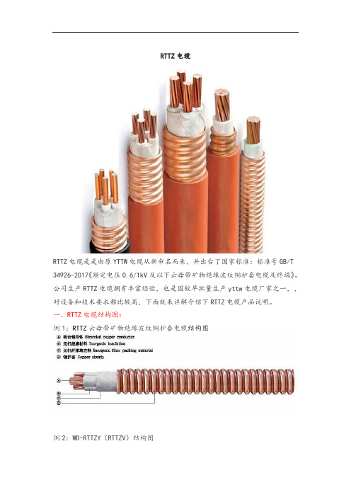
RTTZ电缆RTTZ电缆是是由原YTTW电缆从新命名而来,并出台了国家标准:标准号GB/T 34926-2017《额定电压0.6/1kV及以下云母带矿物绝缘波纹铜护套电缆及终端》。
公司生产RTTZ电缆拥有丰富经验,也是国较早批量生产yttw电缆厂家之一,,对设备和技术要求都比较高,下面就来详解介绍下RTTZ电缆产品说明。
一、RTTZ电缆结构图:例1:RTTZ云母带矿物绝缘波纹铜护套电缆结构图例2:WD-RTTZY(RTTZV)结构图RTTZ系列金属护套无机矿物绝缘电力电缆的导体采用多股铜绞线,绝缘采用耐高温合成云母带机械绕包,绝缘层外采用无碱玻璃纤维密实填充,护套采用铜带纵包后焊接成铜管,再经连续滚轧波纹成型。
特定要求金属护套不能裸露场合,可以在外面加一层聚烯烃(低烟无卤)护套。
二、RTTZ电缆型号规格:RTTZ----铜芯云母带矿物绝缘波纹铜护套控制电缆RTTYZ----铜芯云母带矿物绝缘波纹铜护套聚烯烃外护套控制电缆RTTVZ----铜芯云母带矿物绝缘波纹铜护套聚氯乙烯外护套控制电缆示例1:额定电压 450/750V 铜芯云母带矿物绝缘波纹铜护套控制电缆,规格为 7×1.5mm 2 ,表示为: RTTZ-450/750V 7×1.5示例2:额定电压 0.6/1kV 铜芯云母带矿物绝缘波纹铜护套聚氯乙烯外护套电力电缆,规格为 4×95mm 2 ,表示为:RTTVZ-0.6/1kV 4×95三、RTTZ电缆的性能和优缺点:1、防火性能优越,耐火等级不仅满足国标GB12666 6A类950C ,90min,还可满足英国BS6387-1994中规定的A级650C3h;B级750C3h; C级950C3h要求;同时,在燃烧中还能耐受水喷与机械撞击;2、连续长度长,不管是单芯,还是多芯电缆,其长度能满足供电长度需要,每根连续长度可达1000m以上;3、截面大,单芯电缆截面可达630mm2多芯电缆可达70mm2;4、具有柔性,电缆可以盘在盘上,其弯曲半径6-10D;5、燃烧时无烟无毒,绝缘采用无机材料,燃烧时不会产生任何有害气体,更不会发生2次污染,是真正的环保绿色产品;6、过载能力大,电缆不仅载流量大,而且具有较大的过载能力。
塑料绝缘控制电缆Plasticinsulatedcont-14页word资料

RVS2*2.5标准Q320123TY04-2006电压等级450/750RVS1*1.5标准Q320123TY05-2007电压等级300/500BVR1.5-1.0电压等级450/750ontrol cables以下各种动力、电器仪器及固定或移动式电气设备的控制线路。
V。
缆或有屏蔽层结构的软电缆,应不小于电缆外径的 6倍。
有铠装或铜带屏蔽结构的电缆,应不小于电缆外径KVV 、KVVP450/750 -- 2~37 2~14 2~10KVVP2 -- 4~37 4~14 2~10KVV22 -- 7~37 4~37 4~14 4~10KVVR、KVVRP4~37 -- --5,7,8,10,12,14,16,19,24,27,30,37芯。
括额定电压、芯数和导体标称截面等。
构时,较硬导体用(A)表示,较软导体用(B)表示,在规格后标明,其中(A)可省略。
准电压,用 U0/U表示,单位为V。
、金属套或周围介质)之间的电压有效值。
统任一两相导体之间的电压有效值。
压至少应等于该系统的额定电压。
当使用于直流系统时,该系统的额定电压应不大于电缆额定电压的 1.5 1.1倍。
le以下各种动力、电器仪器、照明及固定或移动式电气设备的连接线路。
为450/750V、300/500V和300/300V。
-90)型电缆的长期允许工作温度应不超过90℃,其它型号电缆的长期允许工作温度应不超过70℃。
小于25mm的,应不小于4D;电缆外径(D)为25mm及以上的,应不小于6D。
括额定电压、芯数和导体标称截面等。
规定,同一型号品种采用规定的不同导体结构时,较硬(第1类)导体用(A)表示,较软(第2类)导体用(B)表准电压。
额定电压用 U0/U表示,单位为V。
属护层或周围介质)之间的电压有效值。
导体之间的电压有效值。
少等于使用电缆系统的标称电压,该条件均适用于 U0和U值。
不大于电缆额定电压的 1.5倍。
标称电压的 10%,如果电缆的额定电压至少等于该系统的标称电压,则电缆可在高于额定电压10%的工作电等标准中有关电缆的额定电压U0/U表示意义与GB 5023-1997完全一ulated cables and wires and cords以下各种动力、电器仪器、照明及固定或移动式电气设备的连接线路。
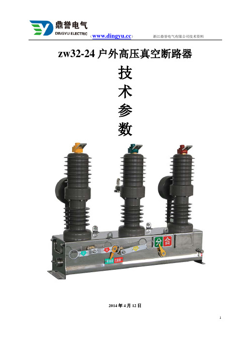
zw32-24户外高压真空断路器技术详细参数
zw32-24户外高压真空断路器技术参数2014年4月12日zw32-24户外高压真空断路器目录1、概述……………………………………………………………………………2、结构特征和工作原理…………………………………………………………3、技术特征………………………………………………………………………4、安装、调试与维护……………………………………………………………5、运输、验收及保管……………………………………………………………6、随机文件………………………………………………………………………7、订货须知………………………………………………………………………8、产品执行的标准及编号………………………………………………………9、隔离部分技术说明……………………………………………………………1zw32-24户外高压真空断路器概述1.1产品型号、名称、规格ZW 32 -12 M /400(630)-16(20)1.2产品用途及使用范围、使用条件ZW32-12 M型zw32-24户外高压真空断路器(以下简断路器)为额定电压12KV,三相交流50HZ的户外配电设备。
主要用于开断、关合电力系统中的负荷电流、过载电流及短路电流。
适用于变电站及工矿企业配电系统中作保护和控制之用,也适用于农村电网及频繁操作场所。
本安装使用说明书规定了断路器的主要技术参数、产品结构、以及操作、安装、使用维护的方法等内容。
1.3使用的环境条件a.海拔高度不超过1000米;b.周围空气温度:-45℃~+40℃日温差:日变化不大于25℃;c.风速不大于35m/s;d.无易燃、爆炸危险、化学腐蚀及剧烈震动的场所。
2.zw32-24户外高压真空断路器结构特征和工作原理2.1断路器总体结构及特点断路器由三相高压系统及内装操动部件的主体箱构成,主体箱上设有供安装固定、吊运用支座和吊身。
外形结构及安装尺寸见图一。
2.1.1装有真空灭弧室的柱上真空断路器开断性能稳定可靠,具有无燃烧和爆炸危险、安全、免维护、体积小、重量轻和使用寿命长等特点。
RD3X中文手册
1.1强化的设计特点
在RD-3X Dytronic设计过程时,许多Radian公司的设计特色被加入并得到了提高,附加了A/D和 DSP技术,加入了计算机支持功能,提高了Radian公司的电压电流互感器输入设计版本,这些技 RD-3X利用Radian设计的A/D线路结合了DSP的技术,这些 术使RD-3X成为便携式标准表的基准。 进步提供给用户高度的灵活性,包括同时、多参数的测量和谐波分析的能力。 A/D和DSP技术 为了加速测试进程,Radian公司已经将特制的A/D积分转换器设计在RD-3X中,有独立的电压和 电流的A/D线路,结合DSP技术的应用,使得RD-3X的性能得到了极大的提高。在独立采集电压 和电流数据时,RD-3X能非常容易采集A/D转换出的数字信号,处理数据,显示各种测量功能。 PC支持 为了增强分析测试能力,每一个RD-3X都有通讯口,这接口允许用户连接个人计算机运行Radian
8
8
3.0 技术条件
3.1 准确度 3.2 输入/输出 3.3 一般操作条件 3.4 准确度影响量 3.5 保护 3.6 外观描述
10
10 10 11 11 12 12
4.0 操作概述
4.1 测量原理 4.2 内部参考标准 4.3 输出方式 4.4 电压电流输入 4.5 辅助电源输入 4.6 钳形电流夹输入 4.7 脉冲输入 4.8 脉冲输出 4.9 模拟信号输入 4.10 串行通讯 4.11 传感器端子l 4.12 机壳接地、地、中性线 4.13 内置计算机 4.14 键盘 4.15 USB 4.16 LVDS 4.17 显示 4.18 RD-3X 电压电流量程划分
RD-3X 三相便携式电量标准表操作手册
目录
1.0产品介绍
1.1 强化的设计特点 1.2 实验室应用 1.3 测试装置中应用 1.4 现场测试应用 1.5 功率分析 1.6 用户负载测试 1.7 自动计算功能 1.8 软件包 1.9 安全设计
PDA TR34文件中文

医疗保健产品生产和检测用隔离系统的设计和验证PDA 技术报告34号2001年9/10月1.0 引言1.1前言近年来,隔离技术迅速出现,作为一种可供选择的人造环境广泛应用于多种医疗保健产品的生产和检测。
隔离系统的性能特征使其可以很理想的用于无菌产品的制备,以及活性物质的隔离。
其它的应用还有临床准备、无菌散装药品/生物制剂、无菌细胞毒素物质的制备,以及无菌检测。
该技术目前没有权威的应用和验证指导,而且关于“隔离系统”和“阻隔器”的概念严重混淆,这是PDA发布此文件的根本动机。
本文件是由美国PDA、日本PDA、A3P、注射药物协会、和德国代表组成的国际委员会制定的。
本文件可用作指导原则;并不作为强制或暗示的标准。
1.2范围本技术报告给出了在医疗保健产品制造工业的生产、开发、检测中广泛应用隔离技术的基本要求。
本技术报告不仅包括产品的无菌保证,也包括了危险物料的隔离。
术语表(附录A)是本技术报告的一个重要组成部分。
医疗保健行业目前没有一整套关于隔离技术的定义。
委员会认为,为了阐述有用的技术信息,我们必须保证读者在应用该技术报告时没有概念的混淆。
委员会也承认在世界的一些地区,在临床制药设备中经过处理的环境条件都叫做“隔离系统”,这些装置与本文定义的隔离系统有着共同的基本特征,然而,它们与现在医疗保健工业中使用的、用于无菌产品的生产和检测的隔离系统有着显著区别。
本技术报告不适用于不符合本文规定和解释的基本标准的设备。
1.3关键定义建立清晰的划分标准来区分是否是隔离系统对于理解本文至关重要。
PDA建议以下关于隔离系统的定义应被全世界医疗保健行业采纳:隔离系统是密封的或者有微生物过滤系统(高效过滤系统HEPA)提供空气并且可以自净化(1)。
当密闭时,仅使用已净化过的内部表面或使用快速传递通道进行物料传递。
当打开时,仅允许物料通过特定的并已经过设计和验证的开口进行进出传递,以排出污染的传递。
它可被用于无菌操作时隔离活性混合物的或者同时用于灭菌处理和隔离。
GJB 3243-1998 电子元器件表面安装要求

电子元器件表面安装要求Surface mount of c01llponents and devices , requirements for 1 范围1.1 主题内容标准规定了表面安装对电子元器件、印制板设计、印制板基材、工艺材料和组装工艺的要求。
1.2 适用范围本标准适用于军用电子装备印制板的电子元器件表面安装。
2 引用文件GB 3 1 31 - 88 锡铅焊料GB 4677.10 - 84 印制板可焊性测试方法CB 4677.22 - 88 印制板表面离子污染测试方法GB 9491 - 88 锡焊用液态焊剂(松香基)CJB 362A - 96 刚性印制板总规范CJB 2 142 - 94 印制线路板用覆金属箔层压板总规范3 定义3.1 术语3.1.1 表面安装 surface mount无需利用印制板元器件插装孔,直接将元器件贴、焊到印制板表面规定位置上的过程。
3.1.2 引线lead从元器件封装体内向外引出的导线。
在表面安装元器件中,指翼形引线、J 形引线、I 形引线等外引线的统称。
3.1.3 引脚leadfoot引线末端的一段,通过软钎焊使这一段与印制板上焊盘共同形成焊点。
3.2 缩写词3.2.1 CFP ceramic flat package陶瓷扁平封装。
3.2.2 CTE coefficient of thermal expansion热膨胀系数。
3.2.3 DIP double in-line package双列直插式封装。
3.2.4 LCC leadless ceramic chip carrier无引线陶瓷芯片载体。
3.2.5 MELF metal electrodes leadless face components金属电极无引线端面元件。
3.2.6 PLCC plastic leaded chip carriers塑料封装有引线芯片载体。
3.2.7 PQFP plastic quad flat package塑料方形扁平封装。
电线内控标准
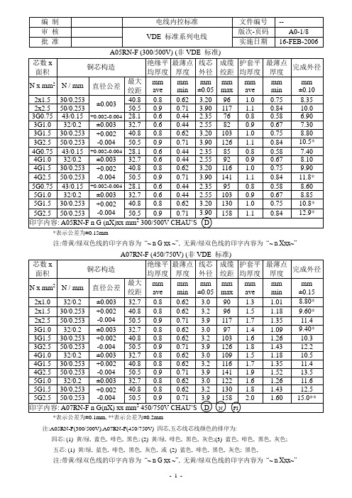
*表示公差为±0.15mm注:带黄/绿双色线的印字内容为“~ n G xx ~”, 无黄/绿双色线的印字内容为“~ n Xxx~”*表示公差为±0.1mm, **表示公差为±0.2mm注:A05RN-F(300/500V),A07RN-F(450/750V) 四芯,五芯线芯线颜色的排序为:四芯: (1) 黄/绿, 蓝色, 啡色, 黑色; (2) 黄/绿, 啡色, 黑色, 灰色;(3) 蓝色, 啡色, 黑色, 灰色;五芯: (1) 黄/绿, 蓝色, 啡色, 黑色, 灰色, 或(2) 蓝色, 啡色, 黑色, 灰色; 黑色,注:带黄/绿双色线的印字内容为“~ n G xx ~”, 无黄/绿双色线的印字内容为“~ n Xxx~”- 1 -H05RR-F (300/500V)*表示公差为±0.08mm **表示公差为±0.15mmH07RN-F (450/750V)1.*表示公差为±0.1mm, **表示公差为±0.2mm,2. 4~5芯目前无KEMA 认证注:H05RR-F(300/500V),H07RN-F(450/750V) 四芯,五芯线芯线颜色的排序为:四芯: (1) 黄/绿, 蓝色, 啡色, 黑色; (2) 黄/绿, 啡色, 黑色, 灰色;(3) 蓝色, 啡色, 黑色, 灰色; 五芯: (1) 黄/绿, 蓝色, 啡色, 黑色, 灰色, 或(2) 蓝色, 啡色, 黑色, 灰色; 黑色,注:带黄/绿双色线的印字内容为“~ n G xx ~”, 无黄/绿双色线的印字内容为“~ nXxx~”1. 印字印在蓝色线芯表面,其余不印字2. 绝缘线芯应与纺纤填充物绞合在一起.绞向必须与线芯导体绞向一致3.编织要求:最少24锭,线股最少60,目数最少700/M.2注:带黄/绿双色线的印字内容为“~ n G xx ~”, 无黄/绿双色线的印字内容“~nXxx~”2*表示公差为±0.08mm注:四芯,五芯线芯线颜色的排序为:四芯: (1) 黄/绿, 蓝色, 啡色, 黑色; (2) 黄/绿, 啡色, 黑色, 灰色;(3) 蓝色, 啡色, 黑色, 灰色; 五芯: (1) 黄/绿, 蓝色, 啡色, 黑色, 灰色, 或(2) 蓝色, 啡色, 黑色, 灰色; 黑色,注:带黄/绿双色线的印字内容为“~ n G xx ~”, 无黄/绿双色线的印字内容为“~ n X xx ~”*表示公差为±0.08mm注:带黄/绿双色线的印字内容为“~ n G xx ~”, 无黄/绿双色线的印字内容为“~ n X xx ~”,*表示公差为±0.08mm注:带黄/绿双色线的印字内容为“~ n G xx ~”, 无黄/绿双色线的印字内容为“~ n X xx ~”,注:四芯,五芯线芯线颜色的排序为: 三芯:黄/绿, 蓝色, 啡色四芯: (1) 黄/绿, 蓝色, 啡色, 黑色; (2) 黄/绿, 啡色, 黑色, 灰色;(3) 蓝色, 啡色, 黑色, 灰色; 五芯: (1) 黄/绿, 蓝色, 啡色, 黑色, 灰色, 或(2) 蓝色, 啡色, 黑色, 灰色; 黑色,*表示公差为±0.08mm注:带黄/绿双色线的印字内容为“~ n G xx ~”, 无黄/绿双色线的印字内容为“~ n X xx ~”,注:四芯,五芯线芯线颜色的排序为:三芯:黄/绿, 蓝色, 啡色四芯: (1) 黄/绿, 蓝色, 啡色, 黑色; (2) 黄/绿, 啡色, 黑色, 灰色;(3) 蓝色, 啡色, 黑色, 灰色; 五芯: (1) 黄/绿, 蓝色, 啡色, 黑色, 灰色, 或(2) 蓝色, 啡色, 黑色, 灰色; 黑色,更改履历页。
ST3243ECPR中文资料

1/18March 2004sESD PROTECTION FOR RS-232I/O PINS:±8KV IEC 1000-4-2CONTACT DISCHARGE ±15KV HUMAN BODY MODELs1µA SUPPLY CURRENT ACHIEVED WHEN IN AUTO-POWERDOWNs250Kbps MINIMUM GUARANTEED DATA RATEs GUARANTEED 6V/µs SLEW RATE RANGE s GUARANTEED MOUSE DRIVEABILITY s 0.1µF EXTERNAL CAPACITORSsMEET EIA/TIA-232SPECIFICATIONS DOWN TO 3VsAVAILABLE IN SO-28,SSOP-28,TSSOP28AND FLIP-CHIP28PACKAGESDESCRIPTIONThe ST3243E device consists of 3drivers,5receivers and a dual charge-pump circuit.The device meets the requirements of EIA/TIA and V.28/V.24communication standards providing high data rate capability and enhanced electrostatic discharge (ESD)protection.All transmitter outputs and receiver input are protected to ±8KV USING IEC 1000-4-2contact discharge and ±15KV using the Human Body Model.The receiver R2is always active to implement a wake-up feature for serial port.The ST3243E has a proprietary low-dropout transmitter output stage enabling true RS-232performance from a 3.0V to 5.5V supply with a dual charge pump.The device is guaranteed to run at data rates of 250kbps while maintaining RS-232output levels.The Auto-powerdown feature functions when FORCEON is low and FORCEOFF is high.During this mode of operation,if the device does not sense a valid RS-232signal,the driver outputs aredisabled.If FORCEOFF is set low,both drivers and receivers (expert R2B)are shut off,and supply current is reduced to 1µA.Disconnecting the serial port or turning off the peripheral drives causes the auto-powerdown condition to occur.Auto-powerdown can be disabled when FORCEON and FORCEOFF are high,and should be done when driving a serial mouse.With Auto-powerdown enabled,the device is activated automatically when a valid signal is applied to any receiver input.Typical application are in notebook,subnotebook,palmtop computers,battery-powered equipment,hand-held equipment,peripherals and printers.ST3243E±15KV ESD PROTECTED 3TO 5.5V,400KBPS,RS-232TRANSCEIVER WITH AUTO-POWERDOWNST3243E2/18ORDERING CODESPIN DESCRIPTIONType Temperature Range PackageCommentsST3243ECD 0to 70°C SO-28(Tube)27parts per tube /12tube per box ST3243EBD -40to 85°C SO-28(Tube)27parts per tube /12tube per boxST3243ECDR 0to 70°C SO-28(Tape &Reel)1000parts per reel ST3243EBDR -40to 85°C SO-28(Tape &Reel)1000parts per reel ST3243ECPR 0to 70°C SSOP-28(Tape &Reel)1350parts per reel ST3243EBPR -40to 85°C SSOP-28(Tape &Reel)1350parts per reel ST3243ECTR 0to 70°C TSSOP28(Tape &Reel)2500parts per reel ST3243EBTR -40to 85°C TSSOP28(Tape &Reel)2500parts per reel ST3243ECJ 0to 70°C FLIP-CHIP28coming soon ST3243EBJ-40to 85°CFLIP-CHIP28coming soonPlN N°SYMBOL NAME AND FUNCTION1C 2+Positive Terminal of Inverting Charge Pump Capacitor 2C 2-Negative Terminal of Inverting Charge Pump Capacitor 3V--5.5V Generated by the Charge Pump 4R1IN First Receiver Input Voltage 5R2IN Second Receiver Input Voltage 6R3IN Third Receiver Input Voltage 7R4IN Fourth Receiver Input Voltage 8R5IN Fifth Receiver Input Voltage 9T1OUT First Transmitter Output Voltage 10T2OUT Second Transmitter Output Voltage 11T3OUT Third Transmitter Output Voltage 12T3IN Third Transmitter Input Voltage 13T2IN Second Transmitter Input Voltage 14T1IN First Transmitter Input Voltage 15R5OUT Fifth Receiver Output Voltage 16R4OUT Fourth Receiver Output Voltage 17R3OUT Third Receiver Output Voltage 18R2OUT Second Receiver Output Voltage 19R1OUT First Receiver Output Voltage20R2OUTB Non-inverting Complementary Receiver Output,always active for wake-up21INVALID Output of the valid signal detector.Indicates if a valid RS-232level is present on receiver inputs logic "1"22FORCEOFF Drive low to shut down transmitters and on-board powersupply.This over-rides all automatic circuitry and FORCEON 23FORCEONDrive high to override automatic circuitry keeping transmitters on (FORCEOFF must be high)24C 1-Negative Terminal of Voltage-Charge Pump Capacitor 25GND Ground26V CC Supply Voltage27V+ 5.5V Generated by the Charge Pump28C 1+Positive Terminal of Voltage-Charge Pump CapacitorST3243E3/18PIN DESCRIPTIONPlN N°SYMBOL NAME AND FUNCTIONA1R2IN Second Receiver Input Voltage A2R3IN Third Receiver Input Voltage A3R4IN Fourth Receiver Input Voltage A4R5IN Fifth Receiver Input Voltage A5T1OUT First Transmitter Output Voltage A6T2OUT Second Transmitter Output Voltage B1V--5.5V Generated by the Charge Pump B2R1IN First Receiver Input Voltage B3T3OUT Third Transmitter Output Voltage B4T3IN Third Transmitter Input Voltage B5T1IN First Transmitter Input Voltage B6T2IN Second Transmitter Input VoltageC1C 2+Positive Terminal of Inverting Charge Pump Capacitor C2C 2-Negative Terminal of Inverting Charge Pump Capacitor C5R4OUT Fourth Receiver Output Voltage C6R5OUT Fifth Receiver Output VoltageD1C 1+Positive Terminal of Voltage-Charge Pump Capacitor D2V+ 5.5V Generated by the Charge Pump D3V CC Supply VoltageD4FORCEON Drive high to override automatic circuitry keeping transmitters on (FORCEOFF must be high)D5R1OUT First Receiver Output Voltage D6R3OUT Third Receiver Output VoltageE1GND GroundE2C 1-Negative Terminal of Voltage-Charge Pump Capacitor E3FORCEOFF Drive low to shut down transmitters and on-board powersupply.This over-rides all automatic circuitry and FORCEON E4INVALID Output of the valid signal detector.Indicates if a valid RS-232level is present on receiver inputs logic "1"E5R2OUTB Non-inverting Complementary Receiver Output,always active for wake-upE6R2OUTSecond Receiver Output VoltageST3243E4/18PIN CONFIGURATIONINVALID TRUTH TABLEOUTPUT CONTROL TRUTH TABLERS-232SIGNAL PRESENT AT ANY RECEIVER INPUTINVALID OUTPUTYES H NOLFORCE ON FORCE OFF VALID RECEIVERLEVELOPERATION STATUS T OUT R OUT R 2OUTB X 0X Shutdown (Force OFF)HIGH Z HIGH Z ACTIVE 11X Normal Operating (ForceON)ACTIVE ACTIVE ACTIVE 01YES Normal Operating (Auto-powerdown)ACTIVE ACTIVE ACTIVE 01NOShutdown (Auto-powerdown)HIGH ZACTIVEACTIVEST3243E5/18ABSOLUTE MAXIMUM RATINGSAbsolute Maximum Ratings are those values beyond which damage to the device may occur.Functional operation under these condition is not implied.ESD PERFORMANCE:TRANSMITTER OUTPUTS,RECEIVER INPUTSELECTRICAL CHARACTERISTICS(C 1-C 4=0.1µF,V CC =3V to 5.5V,T A =-40to 85°C,unless otherwise specified.Typical values are referred to T A =25°C)LOGIC INPUT ELECTRICAL CHARACTERISTICS(C 1-C 4=0.1µF,V CC =3V to 5.5V,T A =-40to 85°C,unless otherwise specified.Typical values are referred to T A =25°C)Symbol ParameterValue Unit V CC Supply Voltage-0.3to 6V V+Doubled Voltage Terminal(V CC -0.3)to 7V V-Inverted Voltage Terminal0.3to -7V V++|V-|13V FORCEON,FORCEOFF,T INInput Voltage -0.3to 6VR IN Receiver Input Voltage Range ± 25V T OUTTransmitter Output Voltage Range± 13.2V R OUT R OUTB INVALID Receiver Output Voltage Range -0.3to (V CC +0.3)Vt SHORT Short Circuit Duration on T OUT (one at a time)Continuous T stgStorage Temperature Range-65to 150°C Symbol ParameterTest ConditionsMin.Typ.Max.Unit ESD ESD Protection Voltage Human Body Model± 15KV ESDESD Protection VoltageIEC 1000-4-2(Contact Discharge)± 8KVSymbol ParameterTest ConditionsMin.Typ.Max.Unit I ASHDNSupply Current Auto-powerdown FORCEOFF =GNDFORCEON =V CC All R_IN open or grounded110µA I SUPPLY Supply Current FORCEON =FORCEOFF =V CC 0.31mA I SHDNShutdown Supply CurrentFORCEOFF =GND110µASymbol ParameterTest ConditionsMin.Typ.Max.Unit V TIL Input Logic Threshold Low T-IN,FORCEON,FORCEOFF 0.8V V TIHInput Logic Threshold HighT-IN,FORCEON,FORCEOFF V CC =3.3V V CC =5V22.4V V V THYS Transmitter Input Hysteresis0.5V I IL Input Leakage Current T-IN,FORCEON,FORCEOFF ± 0.01± 1.0µA I OL Output Leakage Current Receiver Disabled ± 0.05± 10µA V OL Output Voltage Low I OUT =1.6mA 0.4V V OHOutput Voltage HighI OUT =-1mAV CC -0.6V CC -0.1VST3243E6/18AUTO-POWERDOWN ELECTRICAL CHARACTERISTICS(C 1-C 4=0.1µF,V CC =3V to 5.5V,T A =-40to 85°C,unless otherwise specified.Typical values are referred to T A =25°C,FORCEON =GND,FORCEOFF =V CC )TRANSMITTER ELECTRICAL CHARACTERISTICS(C 1-C 4=0.1µF,V CC =3V to 5.5V,T A =-40to 85°C,unless otherwise specified.Typical values are referred to T A =25°C)RECEIVER ELECTRICAL CHARACTERISTICS(C 1-C 4=0.1µF,V CC =3V to 5.5V,T A =-40to 85°C,unless otherwise specified.Typical values are referred to T A =25°C)Symbol ParameterTest ConditionsMin.Typ.Max.Unit V RITE Receiver Input Threshold to INVALID Output Voltage HIGH (Fig.1)Positive Threshold 2.7V Negative Threshold2.7V V RITD Receiver Input Threshold to INVALID Output Voltage LOW (Fig.1)-0.30.3VV IOL INVALID Output Voltage LOWI OUT =1.6mA 0.4V V IOH INVALID Output Voltage HIGHI OUT =-1mAV CC -0.6V t WU Receiver or Transmitter Edge Transmitter Enabled (Fig.1)100µst INVHReceiver Positive or Negative Threshold to INVALID HIGH (Fig.1)0.2µst INVLReceiver Positive or Negative Threshold to INVALID LOW (Fig.1)30µsSymbol ParameterTest ConditionsMin.Typ.Max.Unit V TOUT Output Voltage Swing All Transmitter outputs are loaded with 3K Ωto GND± 5± 5.4V R OUT Output ResistanceV CC =V+=V-=0V V OUT =±2V30010M ΩI SC Output Short Circuit Current V CC =3.3V± 40± 60mA I L Output Leakage Current V CC =0to 5.5V,transmitter output=±12V,transmitter disabled± 25µA V OTTransmitter Output Voltage T1IN =T2IN =GND,T3IN =V CCT3OUT loaded with 3K Ωto GNDT1OUT and T2OUT loaded with 2.5mA each± 5VSymbol ParameterTest ConditionsMin.Typ.Max.Unit V RIN Receiver Input Voltage Operating Range-2525V V RIL RS-232Input Threshold LowT A =25°C V CC =3.3V T A =25°C V CC =5.0V 0.60.81.11.4V V RIHRS-232Input Threshold HighT A =25°C V CC =3.3V T A =25°C V CC =5.0V1.61.92.42.4V V RIHYS Input Hysteresis 0.5V R RIN Input ResistanceT A =25°C357K ΩST3243E7/18TIMING CHARACTERISTICS(C 1-C 4=0.1µF,V CC =3V to 5.5V,T A =-40to 85°C,unless otherwise specified.Typical values are referred to T A =25°C)Symbol ParameterTest ConditionsMin.Typ.Max.Unit D R Maximum Data RateR L =3K ΩC L =1000pF one transmitter switching250400Kbps t PHL t PLHReceiver Propagation Delay R IN to R OUT C L =150pF0.15µs t T_SKEW Transmitter Skew 150ns t R_SKEW Receiver Skew 70nsS RTTransition Slew RateT A =25°C R L =3K to 7K Ω V CC =3.3V measured from +3V to -3V or -3V to +3V C L =150pF to 1000pF C L =150pF to 2500pF643030V/µs V/µsST3243E8/18APPLICATION CIRCUITSREQUIRED MINIMUM CAPACITANCE VALUE (µF)V CC (V)C 1C 2,C 3,C 4,C BYPASS3to 3.60.10.14.5to 5.50.0470.33ST3243E9/18AUTOPOWERDOWN INPUT LEVELSAUTOPOWERDOWN INPUTTIMINGInformation furnished is believed to be accurate and reliable. However, STMicroelectronics assumes no responsibility for the consequences of use of such information nor for any infringement of patents or other rights of third parties which may result from its use. No license is granted by implication or otherwise under any patent or patent rights of STMicroelectronics. Specifications mentioned in this publication are subject to change without notice. This publication supersedes and replaces all information previously supplied. STMicroelectronics products are not authorized for use as critical components in life support devices or systems without express written approval of STMicroelectronics.The ST logo is a registered trademark of STMicroelectronicsAll other names are the property of their respective owners© 2004 STMicroelectronics - All Rights ReservedSTMicroelectronics GROUP OF COMPANIESAustralia - Belgium - Brazil - Canada - China - Czech Republic - Finland - France - Germany - Hong Kong - India - Israel - Italy - Japan - Malaysia - Malta - Morocco - Singapore - Spain - Sweden - Switzerland - United Kingdom - United States.18/18。
RJK0330DPB中文资料
RJK0330DPBSilicon N Channel Power MOS FETPower SwitchingREJ03G1639-0400Rev.4.00Apr 10, 2008Features• High speed switching• Capable of 4.5 V gate drive• Low drive current• High density mounting• Low on-resistanceR DS(on) = 2.1 mΩ typ. (at V GS = 10 V)• Pb-freeOutlineAbsolute Maximum Ratings(Ta = 25°C)UnitRatingsItem SymbolDrain to source voltage V DSS 30 VGate to source voltage V GSS±20 VDrain current I D 45 ADrain peak current I D(pulse)Note1 180 ABody-drain diode reverse drain current I DR 45 A Avalanche current I AP Note 2 22 A Avalanche energy E AR Note 2 48.4 mJChannel dissipation Pch Note3 55 WChannel to Case Thermal Resistance θch-C 2.27 °C/WChannel temperature Tch 150 °CStorage temperature Tstg –55 to +150 °CNotes: 1. PW ≤ 10 µs, duty cycle ≤ 1%2. Value at Tch = 25°C, Rg ≥ 50 Ω3. Tc = 25°CElectrical Characteristics(Ta = 25°C)Item Symbol Min Typ Max Unit Test ConditionsDrain to source breakdownvoltageV (BR)DSS 30 — — V I D = 10 mA, V GS = 0 Gate to source leak current I GSS — — ±0.1 µA V GS = ±20 V, V DS = 0 Zero gate voltage drain current I DSS — — 1 µA V DS = 30 V, V GS = 0 Gate to source cutoff voltage V GS(off) 1.2 — 2.5 V V DS = 10 V, I D = 1 mAR DS(on) — 2.1 2.7 m Ω I D = 22.5 A, V GS = 10 V Note4 Static drain to source on stateresistance R DS(on) — 2.8 3.9 m Ω I D = 22.5 A, V GS = 4.5 V Note4 Forward transfer admittance |y fs | — 90 — S I D = 22.5 A, V DS = 10 V Note4 Input capacitance Ciss — 4300 — pF Output capacitance Coss — 800 — pFReverse transfer capacitance Crss — 245 — pF V DS = 10 V, V GS = 0,f = 1 MHz Gate Resistance Rg — 0.4 — Ω Total gate charge Qg — 27 — nC Gate to source charge Qgs — 10.5 — nCGate to drain charge Qgd — 5.8 — nC V DD = 10 V, V GS = 4.5 V,I D = 45 A Turn-on delay time t d(on) — 6.8 — ns Rise time t r — 3.9 — nsTurn-off delay time t d(off) — 50 — ns Fall timet f — 5.4 — ns V GS = 10 V, I D = 22.5 A,V DD ≅ 10 V, R L = 0.44 Ω, Rg = 4.7 Ω Body–drain diode forward voltage V DF — 0.78 1.02 V I F = 45 A, V GS = 0 Note4 Body–drain diode reverse recovery timet rr — 36 — ns I F = 45 A, V GS = 0di F / dt = 100 A/ µs Body–drain diode reverse recovery charge Q rr — 34 — nCNotes: 4. Pulse testMain CharacteristicsPackage DimensionsOrdering InformationPart No. Quantity Shipping Containerpcs TapingRJK0330DPB-00-J0 2500Refer to "/en/network " for the latest and detailed information.Renesas Technology America, Inc.450 Holger Way, San Jose, CA 95134-1368, U.S.A Tel: <1> (408) 382-7500, Fax: <1> (408) 382-7501Renesas Technology Europe LimitedDukes Meadow, Millboard Road, Bourne End, Buckinghamshire, SL8 5FH, U.K.Tel: <44> (1628) 585-100, Fax: <44> (1628) 585-900Renesas Technology (Shanghai) Co., Ltd.Unit 204, 205, AZIACenter, No.1233 Lujiazui Ring Rd, Pudong District, Shanghai, China 200120Tel: <86> (21) 5877-1818, Fax: <86> (21) 6887-7858/7898Renesas Technology Hong Kong Ltd.7th Floor, North Tower, World Finance Centre, Harbour City, Canton Road, Tsimshatsui, Kowloon, Hong Kong Tel: <852> 2265-6688, Fax: <852> 2377-3473Renesas Technology Taiwan Co., Ltd.10th Floor, No.99, Fushing North Road, Taipei, Taiwan Tel: <886> (2) 2715-2888, Fax: <886> (2) 3518-3399Renesas Technology Singapore Pte. Ltd.1 Harbour Front Avenue, #06-10, Keppel Bay Tower, Singapore 098632 Tel: <65> 6213-0200, Fax: <65> 6278-8001Renesas Technology Korea Co., Ltd.Kukje Center Bldg. 18th Fl., 191, 2-ka, Hangang-ro, Yongsan-ku, Seoul 140-702, Korea Tel: <82> (2) 796-3115, Fax: <82> (2) 796-2145Renesas Technology Malaysia Sdn. BhdUnit 906, Block B, Menara Amcorp, Amcorp Trade Centre, No.18, Jln Persiaran Barat, 46050 Petaling Jaya, Selangor Darul Ehsan, Malaysia Tel: <603> 7955-9390, Fax: <603> 7955-9510RENESAS SALES OFFICES。
RJU中文资料
Document Number: 31035For Technical Questions, contact, ff2aresistors@Document Number: 31035For Technical Questions, contact, ff2aresistors@Disclaimer Legal Disclaimer NoticeVishayAll product specifications and data are subject to change without notice.Vishay Intertechnology, Inc., its affiliates, agents, and employees, and all persons acting on its or their behalf (collectively, “Vishay”), disclaim any and all liability for any errors, inaccuracies or incompleteness contained herein or in any other disclosure relating to any product.Vishay disclaims any and all liability arising out of the use or application of any product described herein or of any information provided herein to the maximum extent permitted by law. The product specifications do not expand or otherwise modify Vishay’s terms and conditions of purchase, including but not limited to the warranty expressed therein, which apply to these products.No license, express or implied, by estoppel or otherwise, to any intellectual property rights is granted by this document or by any conduct of Vishay.The products shown herein are not designed for use in medical, life-saving, or life-sustaining applications unless otherwise expressly indicated. Customers using or selling Vishay products not expressly indicated for use in such applications do so entirely at their own risk and agree to fully indemnify Vishay for any damages arising or resulting from such use or sale. Please contact authorized Vishay personnel to obtain written terms and conditions regarding products designed for such applications.Product names and markings noted herein may be trademarks of their respective owners.元器件交易网Document Number: 。
Z-15GQ3中文资料(omron)中文数据手册「EasyDatasheet - 矽搜」
Z-01H Z-01H-B Z-01HS Z-01HS-B Z-01HD Z-01HD-B --Z-01HQ Z-01HQ-B -------------
---
Z-15EQ Z-15EQ-B --Z-15EQ22
-----------
Z-15EQ22-B Z-15EQ21 Z-15EQ21-B -------
E (1.8 mm)
模型
H (0.25 mm)
模型
Z-15GW54 Z-15GW54-B Z-15GW2277
平行
lever
单向 短铰链滚轮
-----------
-----------
-----------
-----------
lever
反向铰链杆
Z-15GW2277-B Z-15GM Z-15GM-B Z-15GM22 Z-15GM22-B Z-15GM2 Z-15GM2-B
1.额定值 01:0.1 A(微负荷) 15: 15 A
4.防护等级 W44: W78:
无:通用 55: 防滴 A55:防滴 (包括终端)
无:引脚柱塞 S: 超薄弹簧柱塞 D: 短弹簧柱塞 2.接触间隙 K: 弹簧柱塞(中OP) H2: 0.20 mm K3:弹簧柱塞(高OP) (超高灵敏度)Q3:面板安装柱塞(低OP)
• •
这些交换机使用一个橡胶套管上情况之间致动器和粘合剂填充和 覆盖,以增加耐滴水. 模型与防滴端子防护护盖并用树脂充填模终端也可提供.
芯片中文手册,看全文,戳
■ 型号图例
基本模式
Z1234
5
3.执行器
长铰链杆 小力 线 铰链杆(低) W52: 小力 线 铰链杆(高) W22: 短铰链滚轮摇臂 W2: 铰链滚轮摇臂 W25: 铰链滚轮摇臂 (大滚子) W49: 短铰链 交叉滚子杠杆 W54: 铰链交叉滚子杠杆 W2277:单向短铰链 摆杆(低) M: 反向铰链杆 M22: 反向短铰链滚轮摇臂 M2: 反向铰链滚轮摇臂 NJ: 柔性杆(高) NJS: 柔性杆(低)
RJZ-3.315S资料

Deviation from Nominal (%)
2415 0515
25.000 20.000 15.000 10.000 5.000 0.000 -5.000
2405 0505
20.000 15.000 10.000 5.000 0.000 -5.000
2409 0509
1215
0% 20% 40% 60% Total Output current (%) 80% 100%
4kV (H) (H) (H) (H) (H) (H)
RGZ-xx3.3D (H) RGZ-xx05D RGZ-xx09D RGZ-xx12D RGZ-xx15D (H) (H) (H) (H)
RGZ-xx24D (H) 3.3,5,9,12,15,24 ±24 ±42 xx = Input Voltage * add Suffix “P” for Continuous Short Circuit Protection, e.g. RGZ-0524D/P, P e.g. RGZ-0524D/HP, has 4kV Isolation and is Short Circuit Protected.
0% 20% 40% 60% Total Output current (%)
80%
100%
0% 20% 40% 60% Total Output current (%)
80%
0% 20% 40% 60% Total Output current (%)
80%
100%
Deviation / Load
ECONOLINE
DC/DC-Converter
Typical Characteristics
LM324中文资料大全.(DOC)

LM324中文资料大全来源:21ic作者:LM324系列器件带有真差动输入的四运算放大器。
与单电源应用场合的标准运算放大器相比,它们有一些显著优点。
该四放大器可以工作在低到3.0伏或者高到32伏的电源下,静态电流为MC1741的静态电流的五分之一。
共模输入范围包括负电源,因而消除了在许多应用场合中采用外部偏置元件的必要性。
每一组运算放大器可用图1所示的符号来表示,它有5个引出脚,其中“+”、“-”为两个信号输入端,“V+”、“V-”为正、负电源端,“Vo”为输出端。
两个信号输入端中,Vi-(-)为反相输入端,表示运放输出端Vo的信号与该输入端的位相反;Vi+(+)为同相输入端,表示运放输出端Vo的信号与该输入端的相位相同。
LM324系列由四个独立的,高增益,内部频率补偿运算放大器,其中专为从单电源供电的电压范围经营。
从分裂电源的操作也有可能和低电源电流消耗是独立的电源电压的幅度。
应用领域包括传感器放大器,直流增益模块和所有传统的运算放大器现在可以更容易地在单电源系统中实现的电路。
例如,可直接操作的LM324系列,这是用来在数字系统中,轻松地将提供所需的接口电路,而无需额外的±15V电源标准的5V电源电压。
运放类型:低功率放大器数目:4带宽:1.2MHz针脚数:14工作温度范围:0°C to +70°C封装类型:SOIC3dB带宽增益乘积:1.2MHz变化斜率:0.5V/μs器件标号:324器件标记:LM324AD增益带宽:1.2MHz工作温度最低:0°C工作温度最高:70°C放大器类型:低功耗温度范围:商用电源电压最大:32V电源电压最小:3V芯片标号:324表面安装器件:表面安装输入偏移电压最大:7mV运放特点:高增益频率补偿运算逻辑功能号:324额定电源电压, +:15V1.短路保护输出2.真差动输入级3.可单电源工作:3V-32V4.低偏置电流:最大100nA5.每封装含四个运算放大器。
2354中文资料

● Slot technology, Lizt wire recommended for proximity and skin effects reduction
● Mains insulation according to IEC60065 and IEC60950 safety standards
元器件交易网
Consumer Products
CONSUMER PRODUCTS
Pulse offers a complete range of Switch-Mode Transformers in various technologies (slot, layer and triple insulation wire) used for power supplies in television, set-top boxes, satellite receivers, DVD players, telephone chargers, and white goods. Pulse also offers a new range of specific magnetics for LCD TV power supplies and inverters to meet the growing, worldwide demand for flat-screen televisions. These innovative, components are manufactured in state-of-the-art, modern facilities. Switch-Mode Transformers, as well as new LCD components are produced in one of four different factories in China, depending on the technology. The products mentioned in this section serve as an overview of Pulse’s Consumer magnetics product line. For more information about Consumer products, contact Pulse Consumer Division Applications Engineering via e-mail at consumer@.
- 1、下载文档前请自行甄别文档内容的完整性,平台不提供额外的编辑、内容补充、找答案等附加服务。
- 2、"仅部分预览"的文档,不可在线预览部分如存在完整性等问题,可反馈申请退款(可完整预览的文档不适用该条件!)。
- 3、如文档侵犯您的权益,请联系客服反馈,我们会尽快为您处理(人工客服工作时间:9:00-18:30)。
20 0
0% 20% 40% 60% Total Output current (%)
80%
100%
0% 20% 40% 60% Total Output current (%)
80%
0% 20% 40% 60% Total Output current (%)
80%
100%
Deviation / Load
1209
0% 20% 40% 60% Total Output current (%) 80% 100%
2412
0% 20% 40% 60% Total Output current (%) 80% 100%
RJZ-xx15S
Efficiency / Load
100 80 60 40
1215 0515
0% 20% 40% 60% Total Output current (0% 60% Total Output current (%)
80%
0% 20% 40% 60% Total Output current (%)
80%
100%
Deviation / Load
Output Power (%)
100 80 60 40 30 20 0
Derating-Graph
(Ambient Temperature)
120pF max. 15GΩ min. 1 Second Continuous -40°C to +85°C (see Graph) -55°C to +125°C 95% RH 2.8g continued on next page July-2006
ECONOLINE
DC/DC-Converter
RJZ & RGZ Series
2 Watt DIP14 Single & Dual Output
Selection Guide
Part Number DIP 14 RJZ-xx3.3S RJZ-xx05S RJZ-xx09S RJZ-xx12S RJZ-xx15S RJZ-xx24S Input Voltage (VDC) 3.3,5,9,12,15,24 3.3,5,9,12,15,24 3.3,5,9,12,15,24 3.3,5,9,12,15,24 3.3,5,9,12,15,24 3.3,5,9,12,15,24 3.3,5,9,12,15,24 3.3,5,9,12,15,24 3.3,5,9,12,15,24 3.3,5,9,12,15,24 3.3,5,9,12,15,24 Output Voltage (VDC) 3.3 5 9 12 15 24 ±3.3 ±5 ±9 ±12 ±15 Output Current (mA) 606 400 222 166 133 83 ±303 ±200 ±111 ±84 ±66 Efficiency (%) 70-75 78-85 78-84 80-85 82-85 80-85 75 75-82 75-80 78-82 80-84 82-84
元器件交易网
Features
Unregulated Converters
● ● ● ● ● ●
2W Single and Dual Outputs in DIP 14 3kVDC and 4kVDC Isolation Optional Continuous Short Circuit Protected Custom Solutions Available UL94V-0 Package Material Efficiency up to 85%
Safe Operating Area
90 85 Operating Temperature °C
-40
0
50
150
79
元器件交易网
ECONOLINE
DC/DC-Converter
Typical Characteristics
30.000 25.000 30.000
Deviation / Load
30.000 25.000
Deviation / Load
Deviation from Nominal (%)
20.000 15.000 10.000 5.000 0.000 -5.000
Deviation from Nominal (%)
Detailed Information see Application Notes chapter "MTBF"
using MIL-HDBK 217F
Typical Characteristics
RJZ-xx05S
Efficiency / Load
100 80 60 40
0505 2405
RJZ-xx09S
RGZ-xx05D
Efficiency / Load
100 80 60 40
1205 2405 0505
RGZ-xx09D
Efficiency / Load
100 80 60 40
1209 2409 0509
Efficiency %
Efficiency %
20 0
2415
20 0
Efficiency %
1205
0% 20% 40% 60% Total Output current (%) 80% 100%
1209
0% 20% 40% 60% Total Output current (%) 80% 100%
80
July-2006
元器件交易网
Efficiency / Load
100 80 60 40
1209 2409 0509
RJZ-xx12S
Efficiency / Load
100 80 60 40
0512 1212 2412
Efficiency %
Efficiency %
20 0
1205
20 0
Efficiency %
100%
20 0
4kV (H) (H) (H) (H) (H) (H)
RGZ-xx3.3D (H) RGZ-xx05D RGZ-xx09D RGZ-xx12D RGZ-xx15D (H) (H) (H) (H)
RGZ-xx24D (H) 3.3,5,9,12,15,24 ±24 ±42 xx = Input Voltage * add Suffix “P” for Continuous Short Circuit Protection, e.g. RGZ-0524D/P, P e.g. RGZ-0524D/HP, has 4kV Isolation and is Short Circuit Protected.
1205
20.000 15.000 10.000 5.000 0.000 -5.000
Deviation from Nominal (%)
2405
2409 0509
20.000 15.000 10.000 5.000 0.000 -5.000
1212 0512
0505
0% 20% 40% 60% Total Output current (%) 80% 100%
1215 2415
Efficiency %
Efficiency %
20 0
20 0
0% 20% 40% 60% Total Output current (%)
80%
100%
0% 20% 40% 60% Total Output current (%)
80%
100%
Deviation / Load
30.000 25.000 30.000
MTBF (+25°C) using MIL-HDBK 217F
RJZ_RGZ Series
RJZ types RGZtypes RJZ types RGZ types 893 x 103 hours 810 x 103 hours 208 x 103 hours 151 x 103 hours
}
(+85°C)
30.000 25.000 30.000 25.000
Deviation / Load
30.000 25.000
Deviation / Load
Deviation from Nominal (%)
Deviation from Nominal (%)
20.000 15.000 10.000 5.000 0.000 -5.000
EN-60950-1 Certified EN-60601-1 Certified
Specifications (Core Operating Area)
Input Voltage Range Output Voltage Accuracy Line Voltage Regulation Load Voltage Regulation (10% to 100% full load) Output Ripple and Noise (20MHz limited) Temperature Coefficient Operating Frequency Efficiency at Full Load Isolation Voltage (H-Suffix) Rated Working Voltage Isolation Capacitance Isolation Resistance Short Circuit Protection P-Suffix Operating Temperature Range (free air convection) Storage Temperature Range Relative Humidity Package Weight 3.3V Types 5V Types All other Types ±10% ±5% 1.2%/1% of Vin typ. ±20% max. ±15% max. ±10% max. ±150mVp-p max. 0.02%/°C max. 20kHz min./ 50kHz typ. / 90kHz max. (tested for 1 second) (tested for 1 second) (long term isolation) 70% min. / 80% typ. 3000VDC min. 4000VDC min. see Application Notes
