74HC4066
74HC4066中文资料
PS
power dissipation per switch
100 mW
Note
1. To avoid drawing VCC current out of terminal nZ, when switch current flows in terminal nY, the voltage drop across the bidirectional switch must not exceed 0.4 V. If the switch current flows into terminal nZ, no VCC current will flow out of terminal nY. In this case there is no limit for the voltage drop across the switch, but the voltages at nY and nZ may not exceed VCC or GND.
74HC/HCT4066 Quad bilateral switches
Product specification Supersedes data of 1998 Oct 02 File under Integrated Circuits, IC06
1998 Nov 10
元器件交易网
74HC/HCT4066
handbook, halfpage
1
2
13 #
4
3
5#
8
9
6#
11
10
12 #
MGR255
a.
handbook, halfpage
1 1
13 # X1
2 1
4 1
电子系统设计课程设计-量程自动切换的数字电压表设计

同相比例运算电路具有高输入电阻,低输出电阻的优点,但因为集成运放有共模输入,所以为了提高运算精度,应当选用高共模抑制比的集成运放。从另一个角度看,在对电路进行误差分析时,应特别注意共模信号的影响。
2.5数码管显示电路(SM42036系列——共阴极暖色调)
单片机应用系统中,通常都需要进行人机对话。这包括人对应用系统的状态干预与数据输入,以及应用系统向人们显示运行状态与运行结果。显示器、键盘电路就是用来完成人机对话活动的人机通道。这里我们选择普通的四位数码管,而没有采用lcd液晶显示,一方面减低代码编写难度,一方面也节省成本,根据实际需要来选择器件。
2部分电路设计
2.1复位电路
显而易见,复位电路的作用是复位。在单片机接上电源以后,或电源出现过低电压时,将单片机存储器复位,使其各项参数处于初始位置,即处于开机时的标准程序状态,以消除由于某种原因的程序紊乱。单片机的复位电路有上电复位电路和按键式复位电路。上电复位电路——利用电容器充电来实现复位。当加电时,电容上的电压不能突变,RST引脚为高电平,开始复位;电容C不断充电,电阻R上的压降逐步下降,当电容C充满电后,电路相当于开路,复位结束。可见复位的时间与充电的时间有关,充电时间越长复位时间越长,增大电容或电阻都可以增加复位时间。按键式复位电路——它的上电复位功能与上电复位电路相同,但还可以通过按键实现复位。按下按键后,通过两个电阻分压,使RST端产生高电平。按键按下的时间决定了复位的时间。单片机的复位是靠外部电路实现的,在本次设计中采用了按键式复位。
与传统利用手动开关实现通道转换的电压表相比,虽然可以降低成本们根据数据转换很容易地实现了500mv和10v两个量程切换,虽然在切换值处数据变化浮动加快,但是一定时间后仍然会回到稳定的数据显示。
74hc4066工作原理

74hc4066工作原理
74HC4066 是一个四通开关模拟电路芯片,可以控制四个独立信号通路的开关状态。
它采用CMOS技术,由电荷耦合电路构成,主要由四个独立的双刀四通开关组成。
每个开关的控制端有两个输入引脚(S 和 I)。
S引脚用于设置开关的工作模式,高电平表示开关打开,低电平表示开关关闭。
I 引脚用于输入和输出信号,从输入端引入的信号将在上一个引脚连接的输出端输出。
当 S 输入为高电平时,相应的开关打开,输入信号将通过 I 引脚传递到对应的输出端。
当 S 输入为低电平时,相应的开关关闭,输入信号将无法通过开关传递到输出端。
举例来说,如果我们想通过第一个开关传递一个信号,我们可以将 S1 引脚拉高,然后通过 I1 引脚输入信号,信号将被传递到 Q1 引脚输出端。
这样,使用74HC4066芯片,我们可以通过控制开关的状态来选择不同的输入信号路径,从而实现信号的开关和选择功能。
这在很多需要切换信号的应用中非常有用,例如音频选择器、数据选择器等。
HD74HC4066FPEL中文资料

HD74HC4066Quad Analog Switches/Quad MultiplexersREJ03D0651-0200(Previous ADE-205-538)Rev.2.00Mar 30, 2006 DescriptionThis switch has low “on” resistance and low “off” leakage. It is a bidirectional switch, thus any analog input may be used as an output and vice-versa. Also the HD74HC4066 switch contains linearization circuitry which lowers the “on” resistance and increases switch linearity. The HD74HC4066 device allows control of up to 12 V (peak) analog signals with digital control signals of the same range. Each switch has its own control input which disables each switch when low.Features• High Speed Operation• Wide Operating Voltage: V CC = 2 to 6 V• Low Quiescent Supply Current: I CC (static) = 1 µA max (Ta = 25°C)• Ordering InformationPart Name Package TypePackage Code(Previous Code)PackageAbbreviationTaping Abbreviation(Quantity)HD74HC4066P DILP-14pin PRDP0014AB-B(DP-14AV)P —HD74HC4066FPEL SOP-14 pin (JEITA) PRSP0014DF-B(FP-14DAV)FP EL (2,000 pcs/reel)HD74HC4066RPEL SOP-14 pin (JEDEC) PRSP0014DE-A(FP-14DNV)RP EL (2,500 pcs/reel)HD74HC4066TELL TSSOP-14pin PTSP0014JA-B(TTP-14DV)T ELL(2,000pcs/reel)Note: Please consult the sales office for the above package availability.Function TableControl Switch L OFFH ON GND ≤ Vin ≤ V CCGND ≤ Vout ≤ V CCPin ArrangementLogic DiagramAbsolute Maximum RatingsItem SymbolUnitRatingSupply voltage V CC–0.5 to +7.0 VControl input voltage V C– 0.5 to V CC + 0.5 VSwitch I/O voltage V IN/OUT– 0.5 to V CC + 0.5 V(V CC) I CC +50Supply currentmAmA (GND) I GND –50Switch I/O current (per pin) I IN/OUT±25 mA Control input diode current I IK±20 mA Switch I/O diode current I IOK±20 mAmW Power dissipation P T 500Storage temperature range Tstg –65 to +150 °CRecommended Operating ConditionsItem Symbol Min Typ Max UnitSupply voltageV CC 2 — 6 V Control input voltageV C 0 — V CC V Switch I/O voltage V IN/OUT 0 — V CC V Operating temperature Topr –40 — +85 °C V CC = 2.0 V— 1000 ns V CC = 4.5 V 0—500nsInput rise/fall timeV CC = 6.0 Vt r , t f0 — 400nsElectrical CharacteristicsTa = 25°CTa = –40 to+85°CItem Symbol V CC (V) Min Typ Max Min Max Unit Test Conditions2.0 1.5 — — 1.5 — 4.53.15 — — 3.15 —V IH 6.0 4.2 — — 4.2 —V2.0 — — 0.5 — 0.5 4.5 — — 1.35 — 1.35 Control input voltage V IL6.0 — — 1.8 — 1.8 V 2.0 — 2000 5000 — 6250 4.5 — 100 200 — 250 “ON” resistance R ON6.0 — 60 170 — 210Ω V C = V IHVin = 0 to V CC Iin/out = 1 mA2.0 — 50 — — — 4.5 — 3 — — —∆ON resistance between any two channels ∆R ON6.0 — 2 — — —Ω V C = V IH , Iin/out = 1 mA between any two channelsOFF channel leakage current (switch off)I S (OFF) 6.0 — — ±0.1 — ±1.0 µA V C = V ILV IN = V CC , Vout = GND or, Vin = GND, Vout = V CC OFF channel leakage current (switch on)I S (ON) 6.0 — — ±0.1 — ±1.0µA V C = V IHVin = V CC or GND Control input current Iin 6.0 — — ±0.1 — ±1.0µA Vin = V CC or GNDQuiescent supply current I CC 6.0 — — 1.0 — 10.0 µA Vin = V CC or GNDSwitching Characteristics (C L = 50 pF, Input t r = t f = 6 ns, V EE = GND)Ta = 25°CTa = –40 to +85°CItem Symbol V CC (V) Min Typ Max Min Max Unit Test Conditions2.0 — 25 60 — 75 4.5 — 6 12 — 15t PLH 6.0 — 5 10 — 13ns 2.0 — 25 60 — 75 4.5 — 6 12 — 15Propagation delay time t PHL6.0 — 5 10 — 13nsR L = 10 k Ω Switch input to switch output 2.0 — — 50 — 65 4.5 — 4 10 — 13 Propagation delay timet PLH t PHT 6.0 — — 9 — 11ns R L = 10 k Ω 2.0 — — 115 — 145 4.5 — 10 23 — 29 Output enable timet ZH6.0 — — 20 — 25 ns R L = 1 k Ω 2.0 — — 115 — 145 4.5 — 14 23 — 29 Output disable timet LZ t HZ 6.0 — — 20 — 25 ns R L = 1 k Ω Sine wave distortion 4.5 — 0.05 — — — %R L = 10 k Ω, C L = 50 pF, f IN = 1 kHzBand width (–3 dB)4.5—30———MHz R L = 600 Ω, C L = 50 pF,20 log 10Vout/Vin = –3dB Feed through attenuation4.5 — –50 — — — dB R L = 600 Ω, C L = 50 pF,f IN = 1 MHz2.0 — 25 — — — 4.5 — 60 — — —Cross talk between control input to signal I/O6.0 — 75 — — —mA R L = 600 Ω, C L = 50 pF,f IN = 1 MHz Cross talk between any two switches 4.5 — –50 — — — dB R L = 600 Ω, C L = 50 pF, f IN = 1 MHz2.0 — 20 — — — 4.5 — 30 — — —Maximum control frequency 6.0 — 30 — — —MHz R L = 1 k Ω, C L = 15 pF,Vout = 1/2 (V CC ) Control input capacitance Cin — 5 10 — 10 pF Switch I/O capacitance Cin/out — 6 — — — pF Feed through capacitanceCin/out— 0.5 — —— pFPower dissipation capacitance C PD — 13 — — — pFTest CircuitMaximum Control FrequencyCross talk (Control Input to Switch Output)Cin, Cout, Cin–out (Input, Output, and Feed through Capacitance)R ON: ON ResistanceI S (OFF): OFF Channel Leakage Current (Switch OFF)I S (ON): OFF Channel Leakage Current (Switch ON)t PLH, t PHL: Propagation Delay Time (Switch Input to Switch Output)t ZH, t ZL/t HZ, t LZ: Output Enable and Disable TimePackage Dimensions RENESAS SALES OFFICESRefer to "/en/network" for the latest and detailed information.Renesas Technology America, Inc.450 Holger Way, San Jose, CA 95134-1368, U.S.ATel: <1> (408) 382-7500, Fax: <1> (408) 382-7501Renesas Technology Europe LimitedDukes Meadow, Millboard Road, Bourne End, Buckinghamshire, SL8 5FH, U.K.Tel: <44> (1628) 585-100, Fax: <44> (1628) 585-900Renesas Technology (Shanghai) Co., Ltd.Unit 204, 205, AZIACenter, No.1233 Lujiazui Ring Rd, Pudong District, Shanghai, China 200120Tel: <86> (21) 5877-1818, Fax: <86> (21) 6887-7898Renesas Technology Hong Kong Ltd.7th Floor, North Tower, World Finance Centre, Harbour City, 1 Canton Road, Tsimshatsui, Kowloon, Hong KongTel: <852> 2265-6688, Fax: <852> 2730-6071Renesas Technology Taiwan Co., Ltd.10th Floor, No.99, Fushing North Road, Taipei, TaiwanTel: <886> (2) 2715-2888, Fax: <886> (2) 2713-2999Renesas Technology Singapore Pte. Ltd.1 Harbour Front Avenue, #06-10, Keppel Bay Tower, Singapore 098632Tel: <65> 6213-0200, Fax: <65> 6278-8001Renesas Technology Korea Co., Ltd.Kukje Center Bldg. 18th Fl., 191, 2-ka, Hangang-ro, Yongsan-ku, Seoul 140-702, KoreaTel: <82> (2) 796-3115, Fax: <82> (2) 796-2145Renesas Technology Malaysia Sdn. BhdUnit 906, Block B, Menara Amcorp, Amcorp Trade Centre, No.18, Jalan Persiaran Barat, 46050 Petaling Jaya, Selangor Darul Ehsan, MalaysiaTel: <603> 7955-9390, Fax: <603> 7955-9510© 2006. Renesas Technology Corp., All rights reserved. Printed in Japan.。
74HC系列 全部 功能列表

4位双向通用移位寄存器 4位并行存取移位寄存器 双单稳态多谐振荡器 3—8线译码器(带地扯锁存) 3—8线译码器/多路分配器 八缓冲器/驱动器/接收器 八缓冲器/驱动器/接收器 四总线收发器(三态、反相) 四总线收发器(三态、同相) 八缓冲器/驱动器/接收器 八总线收发器(三态) 8选1数据选择器(三态) 四2输入与非门 四2输入或非门 六反相器 六反相器(OC) 四2输入与门 四2输入与门(OC) 三3输入与非门 三3输入与门 六反相器(施密特触发) 双4输入与非门 双4输入与门 三3输入或非门 8输入与非门 四2输入或门 BCD—十进制译码器 2输入/3输入双与或非门 2输入/3输入双与或门 双J—K触发器(带清除端) 双D型正沿触发器 4位双稳态D型锁存器 双J—K触发器(带预置清除端) 4位幅度比较器 四2输入异或门 从J—K触发器(带清除端) 双J—K正沿触发器
74HC系列全部功能列表
型 号 74HC253 74HC257 74HC259 74HC266 74HC273 74HC279 74HC280 74HC283 74HC298 74HC365 74HC366 74HC367 74HC368 74HC373 74HC374 74HC377 74HC386 74HC390 74HC393 74HC540 74HC541 74HC573 74HC574 74HC589 74HC595 74HC688 74HC4002 74HC4015 74HC4017 74HC4040 74HC4046 74HC4049 74HC4050 74HC4051 功 能 双4选1数据选择器(三态) 四2选1数据选择器(三态) 8位可寻址锁存器 四2输入异或非门(OC) 八D型触发器(带清除端) 四R—S锁存器 9位奇偶数产生器/校验器 4位二进制全加器(带超前进位) 4位2选1数据选择器 六缓冲器/总线驱动(同相) 六缓冲器/总线驱动(反相) 六缓冲器/总线驱动(同相) 六缓冲器/总线驱动(反相) 八D触发器(三态) 八D触发器(三态) 八D触发器 四2输入异或门 双4位十进制计数器 双4位二进制计数器(异步清除) 八缓冲器/总线驱动器 八缓冲器/总线驱动器 八D锁存器(三态) 八D锁存器(三态) 8位输入锁存输出移位寄存器 8位输出锁存移位寄存器 8位数值比较器/等值检测器 从4输入或非门 双4位串入并出移位寄存器 十进制计数器/分配器 12位二进制串行计数器 锁相环 六缓冲器/电平变换器(反相) 六缓冲器/电平变换器(同相) 单8通道模拟开关
74HC系列芯片资料

7474HC4052 74HC4053 74HC4060 74HC4066 74HC4075 74HC42 74HC423A 74HC4514 74HC4538A 74HC4543 74HC51 74HC521 74HC533 74HC534 74HC540 74HC541 74HC58 74HC589 74HC594 74HC595 74HC597 74HC620 74HC623 74HC640 74HC643 74HC646 74HC648 74HC688 74HC7266 74HC73 74HC74A 74HC75 74HC76 74HC85 74HC86 74HC942 74HC943 74LS00 74LS02 74LS03 74LS04 74LS05 74LS08 74LS09 74LS10 74LS109 74LS11 74LS112 74LS113 74LS114 74LS122 74LS123 74LS125 74LS160 74LS136 74LS138 74LS139 74LS14 74HC147 74HC148 74HC149 74LS151 74LS153 74LS155 74LS156 74LS157 74LS158 74LS160A 74LS161A 74LS162A 74LS163A 74LS164 74LS168 74LS169 74LS173 74LS174 74LS175 74LS190 74LS191 74LS192 74LS193 74LS194A 74LS195A 74LS20 74LS21 74LS240 74LS244 74LS245 74LS253 74LS256 74LS257 74LS258 74LS27 74LS279 74LS28 74LS283 74LS30 74LS32 74LS352 74LS367 74LS368A 74LS373 74LS76 74LS379 74LS38 74LS390 74LS393 74LS42 74LS48 74LS49 74LS51 74LS540 74LS541 74LS74 74LS682 74LS684 74LS75 74LS83A 74LS85 74LS86 74LS90 74LS95B 74LS688 74LS136 74LS651 74LS653 74LS670 74LS73A 74、74HC、74LS系列芯片资料2006-9-22 23:06系列 电平 典型传输延迟ns 最大驱动电流(-Ioh/Lol)mA AHC CMOS 8.5 -8/8AHCT COMS/TTL 8.5 -8/8HC COMS 25 -8/8HCT COMS/TTL 25 -8/8ACT COMS/TTL 10 -24/24F TTL 6.5 -15/64ALS TTL 10 -15/64LS TTL 18 -15/24注:同型号的74系列、74HC系列、74LS系列芯片,逻辑功能上是一样的。
CD74HC4066MTG4中文资料
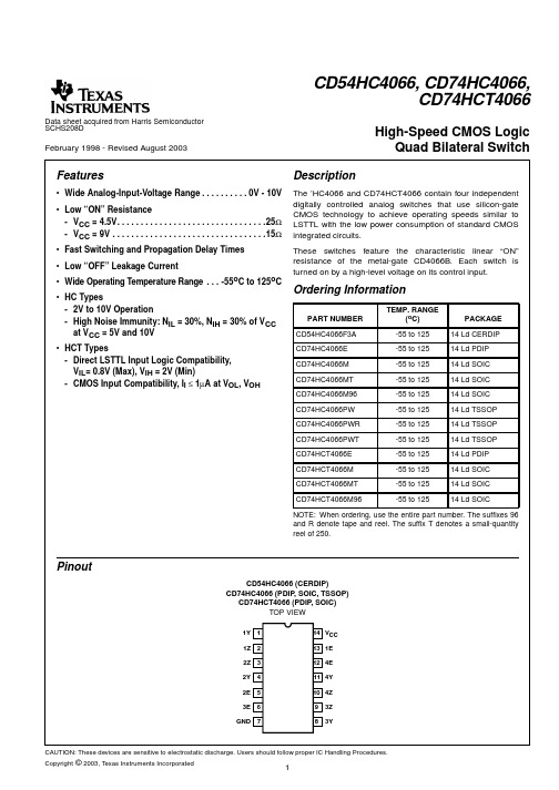
Data sheet acquired from Harris SemiconductorSCHS208DFebruary 1998 - Revised August 2003Features•Wide Analog-Input-Voltage Range. . . . . . . . . .•Low “ON” Resistance-V CC = 4.5V. . . . . . . . . . . . . . . . . . . . . . . . . . . . . . . .25IMPORTANT NOTICETexas Instruments Incorporated and its subsidiaries(TI)reserve the right to make corrections,modifications,enhancements, improvements,and other changes to its products and services at any time and to discontinue any product or service without notice. Customers should obtain the latest relevant information before placing orders and should verify that such information is current and complete.All products are sold subject to TI’s terms and conditions of sale supplied at the time of order acknowledgment.TI warrants performance of its hardware products to the specifications applicable at the time of sale in accordance with TI’s standard warranty.Testing and other quality control techniques are used to the extent TI deems necessary to support this warranty.Except where mandated by government requirements,testing of all parameters of each product is not necessarily performed.TI assumes no liability for applications assistance or customer product design.Customers are responsible for their products and applications using TI components.To minimize the risks associated with customer products and applications,customers should provide adequate design and operating safeguards.TI does not warrant or represent that any license,either express or implied,is granted under any TI patent right,copyright,mask work right,or other TI intellectual property right relating to any combination,machine,or process in which TI products or services are rmation published by TI regarding third-party products or services does not constitute a license from TI to use such products or services or a warranty or endorsement e of such information may require a license from a third party under the patents or other intellectual property of the third party,or a license from TI under the patents or other intellectual property of TI. Reproduction of information in TI data books or data sheets is permissible only if reproduction is without alteration and is accompanied by all associated warranties,conditions,limitations,and notices.Reproduction of this information with alteration is an unfair and deceptive business practice.TI is not responsible or liable for such altered documentation.Resale of TI products or services with statements different from or beyond the parameters stated by TI for that product or service voids all express and any implied warranties for the associated TI product or service and is an unfair and deceptive business practice.TI is not responsible or liable for any such statements.TI products are not authorized for use in safety-critical applications(such as life support)where a failure of the TI product would reasonably be expected to cause severe personal injury or death,unless officers of the parties have executed an agreement specifically governing such use.Buyers represent that they have all necessary expertise in the safety and regulatory ramifications of their applications,and acknowledge and agree that they are solely responsible for all legal,regulatory and safety-related requirements concerning their products and any use of TI products in such safety-critical applications,notwithstanding any applications-related information or support that may be provided by TI.Further,Buyers must fully indemnify TI and its representatives against any damages arising out of the use of TI products in such safety-critical applications.TI products are neither designed nor intended for use in military/aerospace applications or environments unless the TI products are specifically designated by TI as military-grade or"enhanced plastic."Only products designated by TI as military-grade meet military specifications.Buyers acknowledge and agree that any such use of TI products which TI has not designated as military-grade is solely at the Buyer's risk,and that they are solely responsible for compliance with all legal and regulatory requirements in connection with such use.TI products are neither designed nor intended for use in automotive applications or environments unless the specific TI products are designated by TI as compliant with ISO/TS16949requirements.Buyers acknowledge and agree that,if they use anynon-designated products in automotive applications,TI will not be responsible for any failure to meet such requirements. Following are URLs where you can obtain information on other Texas Instruments products and application solutions:Products ApplicationsAmplifiers Audio /audioData Converters Automotive /automotiveDSP Broadband /broadbandInterface Digital Control /digitalcontrolLogic Military /militaryPower Mgmt Optical Networking /opticalnetworkMicrocontrollers Security /securityLow Power /lpw Telephony /telephonyWirelessVideo&Imaging /videoWireless /wirelessMailing Address:Texas Instruments,Post Office Box655303,Dallas,Texas75265Copyright©2007,Texas Instruments IncorporatedPACKAGING INFORMATIONOrderableDevice Status (1)Package Type Package DrawingPins Package Qty Eco Plan (2)Lead/Ball Finish MSL Peak Temp (3)5962-8950701CA ACTIVE CDIP J 141TBD A42SNPB N /A for Pkg Type CD54HC4066F3A ACTIVE CDIP J 141TBD A42SNPB N /A for Pkg Type CD74HC4066E ACTIVE PDIP N 1425Pb-Free (RoHS)CU NIPDAU N /A for Pkg Type CD74HC4066EE4ACTIVE PDIP N 1425Pb-Free (RoHS)CU NIPDAU N /A for Pkg Type CD74HC4066M ACTIVE SOIC D 1450Green (RoHS &no Sb/Br)CU NIPDAU Level-1-260C-UNLIM CD74HC4066M96ACTIVE SOIC D 142500Green (RoHS &no Sb/Br)CU NIPDAU Level-1-260C-UNLIM CD74HC4066M96E4ACTIVE SOIC D 142500Green (RoHS &no Sb/Br)CU NIPDAU Level-1-260C-UNLIM CD74HC4066M96G4ACTIVE SOIC D 142500Green (RoHS &no Sb/Br)CU NIPDAU Level-1-260C-UNLIM CD74HC4066ME4ACTIVE SOIC D 1450Green (RoHS &no Sb/Br)CU NIPDAU Level-1-260C-UNLIM CD74HC4066MG4ACTIVE SOIC D 1450Green (RoHS &no Sb/Br)CU NIPDAU Level-1-260C-UNLIM CD74HC4066MT ACTIVE SOIC D 14250Green (RoHS &no Sb/Br)CU NIPDAU Level-1-260C-UNLIM CD74HC4066MTE4ACTIVE SOIC D 14250Green (RoHS &no Sb/Br)CU NIPDAU Level-1-260C-UNLIM CD74HC4066MTG4ACTIVE SOIC D 14250Green (RoHS &no Sb/Br)CU NIPDAU Level-1-260C-UNLIM CD74HC4066PW ACTIVE TSSOP PW 1490Green (RoHS &no Sb/Br)CU NIPDAU Level-1-260C-UNLIM CD74HC4066PWE4ACTIVE TSSOP PW 1490Green (RoHS &no Sb/Br)CU NIPDAU Level-1-260C-UNLIM CD74HC4066PWG4ACTIVE TSSOP PW 1490Green (RoHS &no Sb/Br)CU NIPDAU Level-1-260C-UNLIM CD74HC4066PWR ACTIVE TSSOP PW 142000Green (RoHS &no Sb/Br)CU NIPDAU Level-1-260C-UNLIM CD74HC4066PWRE4ACTIVE TSSOP PW 142000Green (RoHS &no Sb/Br)CU NIPDAU Level-1-260C-UNLIM CD74HC4066PWRG4ACTIVE TSSOP PW 142000Green (RoHS &no Sb/Br)CU NIPDAU Level-1-260C-UNLIM CD74HC4066PWT ACTIVE TSSOP PW 14250Green (RoHS &no Sb/Br)CU NIPDAU Level-1-260C-UNLIM CD74HC4066PWTE4ACTIVE TSSOP PW 14250Green (RoHS &no Sb/Br)CU NIPDAU Level-1-260C-UNLIM CD74HC4066PWTG4ACTIVE TSSOP PW 14250Green (RoHS &no Sb/Br)CU NIPDAU Level-1-260C-UNLIM CD74HCT4066E ACTIVE PDIP N 1425Pb-Free (RoHS)CU NIPDAU N /A for Pkg Type CD74HCT4066EE4ACTIVE PDIP N 1425Pb-Free (RoHS)CU NIPDAU N /A for Pkg Type CD74HCT4066M ACTIVE SOIC D 1450Green (RoHS &no Sb/Br)CU NIPDAU Level-1-260C-UNLIM CD74HCT4066M96ACTIVESOICD142500Green (RoHS &CU NIPDAULevel-1-260C-UNLIM24-May-2007Orderable DeviceStatus (1)Package Type Package DrawingPins Package QtyEco Plan (2)Lead/Ball FinishMSL Peak Temp (3)no Sb/Br)CD74HCT4066M96E4ACTIVE SOIC D 142500Green (RoHS &no Sb/Br)CU NIPDAU Level-1-260C-UNLIM CD74HCT4066M96G4ACTIVE SOIC D 142500Green (RoHS &no Sb/Br)CU NIPDAU Level-1-260C-UNLIM CD74HCT4066ME4ACTIVE SOIC D 1450Green (RoHS &no Sb/Br)CU NIPDAU Level-1-260C-UNLIM CD74HCT4066MG4ACTIVE SOIC D 1450Green (RoHS &no Sb/Br)CU NIPDAU Level-1-260C-UNLIM CD74HCT4066MT ACTIVE SOIC D 14250Green (RoHS &no Sb/Br)CU NIPDAU Level-1-260C-UNLIM CD74HCT4066MTE4ACTIVE SOIC D 14250Green (RoHS &no Sb/Br)CU NIPDAU Level-1-260C-UNLIM CD74HCT4066MTG4ACTIVESOICD14250Green (RoHS &no Sb/Br)CU NIPDAULevel-1-260C-UNLIM(1)The marketing status values are defined as follows:ACTIVE:Product device recommended for new designs.LIFEBUY:TI has announced that the device will be discontinued,and a lifetime-buy period is in effect.NRND:Not recommended for new designs.Device is in production to support existing customers,but TI does not recommend using this part in a new design.PREVIEW:Device has been announced but is not in production.Samples may or may not be available.OBSOLETE:TI has discontinued the production of the device.(2)Eco Plan -The planned eco-friendly classification:Pb-Free (RoHS),Pb-Free (RoHS Exempt),or Green (RoHS &no Sb/Br)-please check /productcontent for the latest availability information and additional product content details.TBD:The Pb-Free/Green conversion plan has not been defined.Pb-Free (RoHS):TI's terms "Lead-Free"or "Pb-Free"mean semiconductor products that are compatible with the current RoHS requirements for all 6substances,including the requirement that lead not exceed 0.1%by weight in homogeneous materials.Where designed to be soldered at high temperatures,TI Pb-Free products are suitable for use in specified lead-free processes.Pb-Free (RoHS Exempt):This component has a RoHS exemption for either 1)lead-based flip-chip solder bumps used between the die and package,or 2)lead-based die adhesive used between the die and leadframe.The component is otherwise considered Pb-Free (RoHS compatible)as defined above.Green (RoHS &noSb/Br):TI defines "Green"to mean Pb-Free (RoHS compatible),and free of Bromine (Br)and Antimony (Sb)based flame retardants (Br or Sb do not exceed 0.1%by weight in homogeneous material)(3)MSL,Peak Temp.--The Moisture Sensitivity Level rating according to the JEDEC industry standard classifications,and peak solder temperature.Important Information and Disclaimer:The information provided on this page represents TI's knowledge and belief as of the date that it is provided.TI bases its knowledge and belief on information provided by third parties,and makes no representation or warranty as to the accuracy of such information.Efforts are underway to better integrate information from third parties.TI has taken and continues to take reasonable steps to provide representative and accurate information but may not have conducted destructive testing or chemical analysis on incoming materials and chemicals.TI and TI suppliers consider certain information to be proprietary,and thus CAS numbers and other limited information may not be available for release.In no event shall TI's liability arising out of such information exceed the total purchase price of the TI part(s)at issue in this document sold by TI to Customer on an annual basis.24-May-2007TAPE AND REELINFORMATION19-May-2007DevicePackage Pins SiteReel Diameter (mm)Reel Width (mm)A0(mm)B0(mm)K0(mm)P1(mm)W (mm)Pin1Quadrant CD74HC4066M96D 14MLA 33016 6.59.0 2.1816Q1CD74HC4066PWR PW 14MLA 330127.0 5.6 1.6812Q1CD74HCT4066M96D14MLA330166.59.02.1816Q1TAPE AND REEL BOX INFORMATIONDevice PackagePins Site Length (mm)Width (mm)Height (mm)CD74HC4066M96D 14MLA 342.9336.628.58CD74HC4066PWR PW 14MLA 338.1340.520.64CD74HCT4066M96D14MLA342.9336.628.5819-May-200719-May-2007IMPORTANT NOTICETexas Instruments Incorporated and its subsidiaries(TI)reserve the right to make corrections,modifications,enhancements, improvements,and other changes to its products and services at any time and to discontinue any product or service without notice. Customers should obtain the latest relevant information before placing orders and should verify that such information is current and complete.All products are sold subject to TI’s terms and conditions of sale supplied at the time of order acknowledgment.TI warrants performance of its hardware products to the specifications applicable at the time of sale in accordance with TI’s standard warranty.Testing and other quality control techniques are used to the extent TI deems necessary to support this warranty.Except where mandated by government requirements,testing of all parameters of each product is not necessarily performed.TI assumes no liability for applications assistance or customer product design.Customers are responsible for their products and applications using TI components.To minimize the risks associated with customer products and applications,customers should provide adequate design and operating safeguards.TI does not warrant or represent that any license,either express or implied,is granted under any TI patent right,copyright,mask work right,or other TI intellectual property right relating to any combination,machine,or process in which TI products or services are rmation published by TI regarding third-party products or services does not constitute a license from TI to use such products or services or a warranty or endorsement e of such information may require a license from a third party under the patents or other intellectual property of the third party,or a license from TI under the patents or other intellectual property of TI. Reproduction of information in TI data books or data sheets is permissible only if reproduction is without alteration and is accompanied by all associated warranties,conditions,limitations,and notices.Reproduction of this information with alteration is an unfair and deceptive business practice.TI is not responsible or liable for such altered documentation.Resale of TI products or services with statements different from or beyond the parameters stated by TI for that product or service voids all express and any implied warranties for the associated TI product or service and is an unfair and deceptive business practice.TI is not responsible or liable for any such statements.TI products are not authorized for use in safety-critical applications(such as life support)where a failure of the TI product would reasonably be expected to cause severe personal injury or death,unless officers of the parties have executed an agreement specifically governing such use.Buyers represent that they have all necessary expertise in the safety and regulatory ramifications of their applications,and acknowledge and agree that they are solely responsible for all legal,regulatory and safety-related requirements concerning their products and any use of TI products in such safety-critical applications,notwithstanding any applications-related information or support that may be provided by TI.Further,Buyers must fully indemnify TI and its representatives against any damages arising out of the use of TI products in such safety-critical applications.TI products are neither designed nor intended for use in military/aerospace applications or environments unless the TI products are specifically designated by TI as military-grade or"enhanced plastic."Only products designated by TI as military-grade meet military specifications.Buyers acknowledge and agree that any such use of TI products which TI has not designated as military-grade is solely at the Buyer's risk,and that they are solely responsible for compliance with all legal and regulatory requirements in connection with such use.TI products are neither designed nor intended for use in automotive applications or environments unless the specific TI products are designated by TI as compliant with ISO/TS16949requirements.Buyers acknowledge and agree that,if they use anynon-designated products in automotive applications,TI will not be responsible for any failure to meet such requirements. Following are URLs where you can obtain information on other Texas Instruments products and application solutions:Products ApplicationsAmplifiers Audio /audioData Converters Automotive /automotiveDSP Broadband /broadbandInterface Digital Control /digitalcontrolLogic Military /militaryPower Mgmt Optical Networking /opticalnetworkMicrocontrollers Security /securityRFID Telephony /telephonyLow Power /lpw Video&Imaging /videoWirelessWireless /wirelessMailing Address:Texas Instruments,Post Office Box655303,Dallas,Texas75265Copyright©2007,Texas Instruments Incorporated。
74HC系列芯片资料
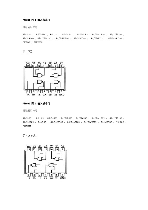
74HC00 四 2 输入与非门国际通用符号54/7400 , 54/74H00 , 54L 00 , 54/74S00 , 54/74LS00 , 54/74ALS00 , 54/ 74F 00 , 54/74HC00 , 54/ 74AC 00 , 54/74HCT00 , 54/74ACT00 , 54/74AHC00 , 54/74AHCT00 ,74LV00 , 74LVC00。
74HC02 四 2 输入或非门国际通用符号54/7402 , 54L 02 , 54/74S02 , 54/74LS02 , 54/74AS02 , 54/74ALS02 , 54/ 74F 02 ,54/74HC02 , 74AC 02 , 54/74HCT02 , 54/74ACT02 , 54/74AHC02 , 54/AHCT02 , 74LV02 , 74LVC02。
74HC04 六反相器国际通用符号54/7404 , 54L 04 , 54/74H04 , 54/74S04 , 54/74LS04 , 54/74AS04 , 54/74ALS04 ,54/ 74F 04 , 54/74HCU04 , 54/74HC04 , 54/ 74AC 04 , 54/74HCT04 , 54/74ACT04 ,54/74AHC04 , 54/74AHCT04 , 74LV04 , 74LVC04 , 54/74AHCU04 , 74LVU04 , 74LVCU04 .74HC08 四 2 输入与门国际通用符号54/7408 , 54/74S08 , 54/74LS08 , 54/74AS08 , 54/74ALS08 , 54/ 74F 08 , 54/74HC08 ,54/74HCT08 , 54/ 74AC 08 , 54/74ACT08 , 54/74AHC08 , 54/74AHCT08 , 74LV08 , 74LVC08。
74HC系列芯片的区别

. HC为COMS工作电平;
. HCT为TTL工作电平,可与74LS系列互换使用;
.HCU适用于无缓冲级的CMOS电路。
这9种74系列产品,只要后边的标号相同,其逻辑功能和管脚排列就相同。根据不同的条件和要求可选择不同类型的74系列产品,比如电路的供电电压为3V就应选择74HC系列的产品
74HC373 3-STATE OCTAL D LATCHES 三态D型锁存器
74HC374 3-STATE OCTAL D FLIPFLOP 三态D触发器
74HC393 4-BIT BINARY COUNTER 4位二进制计数器
74HC4016 QUAD ANALOG SWITCH 四路模拟量开关
74HC163 DECADE COUNTERS 十进制计数器
74HC164 SERIAL-PARALLEL SHIFT REG 串入并出
74HC165 PARALLEL-SERIAL SHIFT REG 并入串出
74HC166 SERIAL-PARALLEL SHIFT REG 串入并出
74HC/LS/HCT/F系列芯片的区别
1、 LS是低功耗肖特基,HC是高速COMS。LS的速度比HC略快。HCT输入输出与LS兼容,但是功耗低;F是高速肖特基电路;
2、 LS是TTL电平,HC是COMS电平。
3、 LS输入开路为高电平,HC输入不允许开路, hc 一般都要求有上下拉电阻来确定输入端无效时的电平。LS 却没有这个要求
7430 8-INPUT NAND GATES 八输入端与非门
7432 QUAD 2-INPUT OR GATES 二输入或门
74HC4066.PDF

independent input/output
4E
enable input (active HIGH)
1E
enable input (active HIGH)
VCC
supply voltage
SWITCH off on
PACKAGE
PINS
PACKAGE
14
DIP14
14
DIP14
14
SO14
14
Fig.4 IEEEC logic symbol. 4
Philips Semiconductors
Quad bilateral switches
Product specification
74HC4066; 74HCT4066
handbook, halfpage13 1 5 4 6 8 12 11 1E 1Y 2E 2Y 3E 3Y 4E 4Y
2004 Nov 11
2
Philips Semiconductors
Quad bilateral switches
Product specification
74HC4066; 74HCT4066
FUNCTION TABLE See note 1.
INPUT nE L H
Note 1. H = HIGH voltage level.
GENERAL DESCRIPTION
The 74HC4066 and 74HCT4066 are high-speed Si-gate CMOS devices and are pin compatible with the HEF4066B. They are specified in compliance with JEDEC standard no. 7A.
M74HC4066B1R中文资料

M54HC4066M74HC4066October 1993QUAD BILATERAL SWITCHB1R(Plastic Package)ORDER CODES :M54HC4066F1R M74HC4066M1R M74HC4066B1R M74HC4066C1RF1R(Ceramic Package)M1R(Micro Package)C1R (Chip Carrier)PIN CONNECTIONS (top view)NC =No Internal Connecti o n.HIGH SPEEDt PD =7ns (TYP.)AT V CC =5V .LOW POWER DISSIPATION I CC =1µA (MAX.)AT T A =25°C .HIGH NOISE IMMUNITYV NIH =V NIL =28%V CC (MIN.).LOW ”ON”RESISTANCER ON =50Ω(TYP.)AT V CC =9V,I I/O =100µA .SINE WAVE DISTORTION.0.042%(TYP.)AT V CC =4V f =1KHz .WIDE OPERATING VOLTAGE RANGE V CC (OPR)=2V TO 12V.PIN AND FUNCTION COMPATIBLE WITH 4066BThe M54/74HC4066is a high speed CMOS QUADBILATERAL SWITCH fabricated in silicon gate C 2MOS technology.It has high speed performance combined with true CMOS low power consumption.The C input is provided to control the switch ;the switch is ON when the C input is held high and off when C is held low.DESCRIPTION1/11LOGIC DIAGRAM IEC LOGIC SYMBOLPIN DESCRIPTIONPIN No SYMBOL NAME AND FUNCTION 1,4,8,111to4I/O IndependentInputs/Outputs 2,3,9,101to4O/I IndependentOutputs/Inputs13,5,6,121C to4C Enable Inputs(ActiveHIGH)7GND Ground(0V)14V CC Positive Supply Voltage TRUTH TABLECONTROL SWITCH FUNCTIONH ONL OFFABSOLUTE MAXIMUM RATINGSSymbol Parameter Value Unit V CC Supply Voltage-0.5to+13V V IN DC Input Voltage-0.5to V CC+0.5V V I/O DC Input/Output Voltage-0.5to V CC+0.5VI OK Control Input DC Diode Current±20mAI IOK I/O DC Diode Current±20mAI O DC Output Source Sink Current Per Output Pin±25mAI CC or I GND DC V CC or Ground Current±50mAP D Power Dissipation500(*)mW T stg Storage Temperature-65to+150o C T L Lead Temperature(10sec)300o C Absolute Maximum Ratings are those values beyond whichdamage to the device may occu r.Functiona l ope ration und er these cond ition isnotimplied. (*)500mW:≅65o C derate to300mW by10mW/o C:65o C to85o CM54/M74HC40662/11RECOMMENDED OPERATING CONDITIONSSymbol Parameter Value Unit V CC Supply Voltage2to12V V IN Input Voltage(Control)0to V CC V V I/O Input/Output Voltage0to V CC VT op Operating Temperature:M54HC SeriesM74HC Series -55to+125-40to+85o Co Ct r,t f Input Rise and Fall Time V CC=2V0to1000nsV CC=4.5V0to500V CC=6V0to400V CC=10V0to250DC SPECIFICATIONSSymbol ParameterTest Conditions ValueUnit V CC(V)T A=25o C54HC and74HC-40to85o C74HC-55to125o C54HCMin.Typ.Max.Min.Max.Min.Max.V IHC High LevelControl InputVoltage 2.0 1.5 1.5 1.5V 4.5 3.15 3.15 3.159.0 6.3 6.3 6.312.08.48.48.4V ILC Low LevelControl InputVoltage 2.00.50.50.5V 4.5 1.35 1.35 1.359.0 2.7 2.7 2.712.0 3.6 3.6 3.6R ON ON Resistance 4.5V IN=V IHCV I/O=V CC to GNDI I/O≤1mA 96170200250Ω9.0558******* 12.04580901204.5V IN=V IHCV I/O=V CC or GNDI I/O≤1mA 701001301609.0507595115 12.0457090110∆R ON Difference of ONResistanceBetween Switches 4.5V IN=V IHCV I/O=V CC or GNDI I/O≤1mA10Ω9.0512.05I OFF Input/OutputLeakage Current (SWITCH OFF)12.0V OS=V CC or GNDV IS=V CC or GNDV IN=V ILC±0.1±1±2µAI IZ Switch InputLeakage Current (SWITCH ON, OUTPUT OPEN)12.0V OS=V CC or GNDV IN=V IHC±0.1±1±2µAI IN Control InputCurrent 6.0V IN=V CC or GND±0.1±1±1µAI CC Quiescent SupplyCurrent 6.0V IN=V CC or GND11020µA 9.04408012.0880160M54/M74HC40663/11AC ELECTRICAL CHARACTERISTICS(C L=50pF,Input t r=t f=6ns)Symbol ParameterTest Conditions ValueUnit V CC(V)T A=25o C54HC and74HC-40to85o C74HC-55to125o C54HCMin.Typ.Max.Min.Max.Min.Max.øI/O Phase DifferenceBetween Inputand Output 2.010506575ns 4.541013159.038101312.037910t PZL t PZH Output EnableTime2.0R L=1KΩ181********ns4.582025309.0612222712.06121825t PLZ t PHZ Output DisableTime2.0R L=1KΩ20115145175ns4.5102329359.0820253012.08182227 Maximum ControlInput Frequency2.0R L=1KΩC L=15pFV OUT=1/2V CC30MHz4.5309.03012.030C IN Input Capacitance5101010pFC I/O Switch TerminalCapacitance 6pFC IOS Feed ThroughCapacitance 0.5pFC PD(*)Power DissipationCapacitance 15pF(*)C PD is defined as the value of the IC’s internal equivalent capac itanc e which is calculated from the operating current con sump tion without load. (Refer to Test Circuit).Average operting current can be obtained by the following equ ation.I CC(opr)=C PD•V CC•f IN+I CCANALOG SWITCH CHARACTERISTICS(GND=0V T A=25o C)Symbol ParameterTest Conditions ValueUnit V CC(V)VIN(Vp-p)Typ.Sine Wave Distortion(THD) 4.54f IN=1KHz R L=10KΩC L=50pF0.05%9.080.04f MAX Frequency Response(Switch ON)4.5Adjust f IN voltage to Obtain0dBm at V OS.Increase f IN Frequency until dB Meter reads-3dBR L=50ΩC L=10pF200MHz 9.0200Feedthrough Attenuation (Switch OFF)4.5V IN is centered at VCC/2.Adjust input for0dBmR L=600ΩC L=50pF f IN=1MHz sine wav e-60dB 9.0-60Crosstalk(Control Input to Signal Output)4.5R L=600ΩC L=50pFf IN=1MHz square wav e(t r=t f=6ns)60mV 9.0100Crosstalk(Between Any Switches)4.5Adjust V IN to Obtain0dBm at inputR L=600ΩC L=50pF f IN=1MHz sine wav e-60dB 9.0-60M54/M74HC4066 4/11M54/M74HC4066SWITCHING CHARACTERISTICS TEST CIRCUITt PLZ,t PHZ,t PZL,t PZH.CROSSTALK(control to output)CROSSTALK BETWEEN ANY TWOSWITCHESBANDWIDTH AND FEEDTHROUGHATTENUATIONGND(V SS)C I–O C I/O MAXIMUM CONTROL FREQUENCYGND(V SS)5/11M54/M74HC4066CHANNEL RESISTANCE(R ON)I CC(Opr.) 6/11M54/M74HC4066 Plastic DIP14MECHANICAL DATAmm inchDIM.MIN.TYP.MAX.MIN.TYP.MAX.a10.510.020B 1.39 1.650.0550.065b0.50.020b10.250.010D200.787E8.50.335e 2.540.100e315.240.600F7.10.280I 5.10.201L 3.30.130Z 1.27 2.540.0500.100P001A7/11M54/M74HC4066Ceramic DIP14/1MECHANICAL DATAmm inch DIM.MIN.TYP.MAX.MIN.TYP.MAX.A200.787 B7.00.276D 3.30.130E0.380.015e315.240.600F 2.29 2.790.0900.110G0.40.550.0160.022H 1.17 1.520.0460.060L0.220.310.0090.012 M 1.52 2.540.0600.100 N10.30.406 P7.88.050.3070.317 Q 5.080.200P053C 8/11M54/M74HC4066SO14MECHANICAL DATAmm inchDIM.MIN.TYP.MAX.MIN.TYP.MAX.A 1.750.068a10.10.20.0030.007a2 1.650.064b0.350.460.0130.018b10.190.250.0070.010C0.50.019c145°(typ.)D8.558.750.3360.344E 5.8 6.20.2280.244e 1.270.050e37.620.300F 3.8 4.00.1490.157G 4.6 5.30.1810.208L0.5 1.270.0190.050M0.680.026S8°(max.)P013G9/11M54/M74HC4066PLCC20MECHANICAL DATAmm inch DIM.MIN.TYP.MAX.MIN.TYP.MAX.A9.7810.030.3850.395 B8.899.040.3500.356D 4.2 4.570.1650.180d1 2.540.100d20.560.022E7.378.380.2900.330e 1.270.050e3 5.080.200F0.380.015G0.1010.004 M 1.270.050M1 1.140.045P027A 10/11元器件交易网M54/M74HC4066 Information furnished is believed to be accurate and reliable.However,SGS-THOMSON Microelectronics assumes no responsability for theconsequences of use of such information nor for any infringement of patents or other rights of third parties which may results from its use.Nolicense is granted by implication or otherwise under any patent or patent rights of SGS-THOMSON Microelectronics.Specificationsmentionedin this publication are subject to change without notice.This publication supersedes and replaces all information previously supplied.SGS-THOMSON Microelectronics products are not authorized for use ascritical components in life support devices or systems without expresswritten approval of SGS-THOMSON Microelectonics.©1994SGS-THOMSON Microelectronics-All Rights ReservedSGS-THOMSON Microelectronics GROUP OF COMPANIESAustralia-Brazil-France-Germany-Hong Kong-Italy-Japan-Korea-Malaysia-Malta-Morocco-The Netherlands-Singapore-Spain-Sweden-Switzerland-Taiwan-Thailand-United Kingdom-U.S.A11/11。
芯片4066介绍

M54HC4066M74HC4066October 1993QUAD BILATERAL SWITCHB1R(Plastic Package)ORDER CODES :M54HC4066F1R M74HC4066M1R M74HC4066B1R M74HC4066C1RF1R(Ceramic Package)M1R(Micro Package)C1R (Chip Carrier)PIN CONNECTIONS (top view)NC =No Internal Connecti o n.HIGH SPEEDt PD =7ns (TYP.)AT V CC =5V .LOW POWER DISSIPATION I CC =1µA (MAX.)AT T A =25°C .HIGH NOISE IMMUNITYV NIH =V NIL =28%V CC (MIN.).LOW ”ON”RESISTANCER ON =50Ω(TYP.)AT V CC =9V,I I/O =100µA .SINE WAVE DISTORTION.0.042%(TYP.)AT V CC =4V f =1KHz .WIDE OPERATING VOLTAGE RANGE V CC (OPR)=2V TO 12V.PIN AND FUNCTION COMPATIBLE WITH 4066BThe M54/74HC4066is a high speed CMOS QUADBILATERAL SWITCH fabricated in silicon gate C 2MOS technology.It has high speed performance combined with true CMOS low power consumption.The C input is provided to control the switch ;the switch is ON when the C input is held high and off when C is held low.DESCRIPTION1/11LOGIC DIAGRAM IEC LOGIC SYMBOLPIN DESCRIPTIONPIN No SYMBOL NAME AND FUNCTION 1,4,8,111to4I/O IndependentInputs/Outputs 2,3,9,101to4O/I IndependentOutputs/Inputs13,5,6,121C to4C Enable Inputs(ActiveHIGH)7GND Ground(0V)14V CC Positive Supply Voltage TRUTH TABLECONTROL SWITCH FUNCTIONH ONL OFFABSOLUTE MAXIMUM RATINGSSymbol Parameter Value Unit V CC Supply Voltage-0.5to+13V V IN DC Input Voltage-0.5to V CC+0.5V V I/O DC Input/Output Voltage-0.5to V CC+0.5VI OK Control Input DC Diode Current±20mAI IOK I/O DC Diode Current±20mAI O DC Output Source Sink Current Per Output Pin±25mAI CC or I GND DC V CC or Ground Current±50mAP D Power Dissipation500(*)mW T stg Storage Temperature-65to+150o C T L Lead Temperature(10sec)300o C Absolute Maximum Ratings are those values beyond whichdamage to the device may occu r.Functiona l ope ration und er these cond ition isnotimplied. (*)500mW:≅65o C derate to300mW by10mW/o C:65o C to85o CM54/M74HC40662/11RECOMMENDED OPERATING CONDITIONSSymbol Parameter Value Unit V CC Supply Voltage2to12V V IN Input Voltage(Control)0to V CC V V I/O Input/Output Voltage0to V CC VT op Operating Temperature:M54HC SeriesM74HC Series -55to+125-40to+85o Co Ct r,t f Input Rise and Fall Time V CC=2V0to1000nsV CC=4.5V0to500V CC=6V0to400V CC=10V0to250DC SPECIFICATIONSSymbol ParameterTest Conditions ValueUnit V CC(V)T A=25o C54HC and74HC-40to85o C74HC-55to125o C54HCMin.Typ.Max.Min.Max.Min.Max.V IHC High LevelControl InputVoltage 2.0 1.5 1.5 1.5V 4.5 3.15 3.15 3.159.0 6.3 6.3 6.312.08.48.48.4V ILC Low LevelControl InputVoltage 2.00.50.50.5V 4.5 1.35 1.35 1.359.0 2.7 2.7 2.712.0 3.6 3.6 3.6R ON ON Resistance 4.5V IN=V IHCV I/O=V CC to GNDI I/O≤1mA 96170200250Ω9.0558******* 12.04580901204.5V IN=V IHCV I/O=V CC or GNDI I/O≤1mA 701001301609.0507595115 12.0457090110∆R ON Difference of ONResistanceBetween Switches 4.5V IN=V IHCV I/O=V CC or GNDI I/O≤1mA10Ω9.0512.05I OFF Input/OutputLeakage Current (SWITCH OFF)12.0V OS=V CC or GNDV IS=V CC or GNDV IN=V ILC±0.1±1±2µAI IZ Switch InputLeakage Current (SWITCH ON, OUTPUT OPEN)12.0V OS=V CC or GNDV IN=V IHC±0.1±1±2µAI IN Control InputCurrent 6.0V IN=V CC or GND±0.1±1±1µAI CC Quiescent SupplyCurrent 6.0V IN=V CC or GND11020µA 9.04408012.0880160M54/M74HC40663/11AC ELECTRICAL CHARACTERISTICS(C L=50pF,Input t r=t f=6ns)Symbol ParameterTest Conditions ValueUnit V CC(V)T A=25o C54HC and74HC-40to85o C74HC-55to125o C54HCMin.Typ.Max.Min.Max.Min.Max.øI/O Phase DifferenceBetween Inputand Output 2.010506575ns 4.541013159.038101312.037910t PZL t PZH Output EnableTime2.0R L=1KΩ181********ns4.582025309.0612222712.06121825t PLZ t PHZ Output DisableTime2.0R L=1KΩ20115145175ns4.5102329359.0820253012.08182227 Maximum ControlInput Frequency2.0R L=1KΩC L=15pFV OUT=1/2V CC30MHz4.5309.03012.030C IN Input Capacitance5101010pFC I/O Switch TerminalCapacitance 6pFC IOS Feed ThroughCapacitance 0.5pFC PD(*)Power DissipationCapacitance 15pF(*)C PD is defined as the value of the IC’s internal equivalent capac itanc e which is calculated from the operating current con sump tion without load. (Refer to Test Circuit).Average operting current can be obtained by the following equ ation.I CC(opr)=C PD•V CC•f IN+I CCANALOG SWITCH CHARACTERISTICS(GND=0V T A=25o C)Symbol ParameterTest Conditions ValueUnit V CC(V)VIN(Vp-p)Typ.Sine Wave Distortion(THD) 4.54f IN=1KHz R L=10KΩC L=50pF0.05%9.080.04f MAX Frequency Response(Switch ON)4.5Adjust f IN voltage to Obtain0dBm at V OS.Increase f IN Frequency until dB Meter reads-3dBR L=50ΩC L=10pF200MHz 9.0200Feedthrough Attenuation (Switch OFF)4.5V IN is centered at VCC/2.Adjust input for0dBmR L=600ΩC L=50pF f IN=1MHz sine wav e-60dB 9.0-60Crosstalk(Control Input to Signal Output)4.5R L=600ΩC L=50pFf IN=1MHz square wav e(t r=t f=6ns)60mV 9.0100Crosstalk(Between Any Switches)4.5Adjust V IN to Obtain0dBm at inputR L=600ΩC L=50pF f IN=1MHz sine wav e-60dB 9.0-60M54/M74HC4066 4/11M54/M74HC4066SWITCHING CHARACTERISTICS TEST CIRCUITt PLZ,t PHZ,t PZL,t PZH.CROSSTALK(control to output)CROSSTALK BETWEEN ANY TWOSWITCHESBANDWIDTH AND FEEDTHROUGHATTENUATIONGND(V SS)C I–O C I/O MAXIMUM CONTROL FREQUENCYGND(V SS)5/11M54/M74HC4066CHANNEL RESISTANCE(R ON)I CC(Opr.) 6/11M54/M74HC4066 Plastic DIP14MECHANICAL DATAmm inchDIM.MIN.TYP.MAX.MIN.TYP.MAX.a10.510.020B 1.39 1.650.0550.065b0.50.020b10.250.010D200.787E8.50.335e 2.540.100e315.240.600F7.10.280I 5.10.201L 3.30.130Z 1.27 2.540.0500.100P001A7/11M54/M74HC4066Ceramic DIP14/1MECHANICAL DATAmm inch DIM.MIN.TYP.MAX.MIN.TYP.MAX.A200.787 B7.00.276D 3.30.130E0.380.015e315.240.600F 2.29 2.790.0900.110G0.40.550.0160.022H 1.17 1.520.0460.060L0.220.310.0090.012 M 1.52 2.540.0600.100 N10.30.406 P7.88.050.3070.317 Q 5.080.200P053C 8/11M54/M74HC4066SO14MECHANICAL DATAmm inchDIM.MIN.TYP.MAX.MIN.TYP.MAX.A 1.750.068a10.10.20.0030.007a2 1.650.064b0.350.460.0130.018b10.190.250.0070.010C0.50.019c145°(typ.)D8.558.750.3360.344E 5.8 6.20.2280.244e 1.270.050e37.620.300F 3.8 4.00.1490.157G 4.6 5.30.1810.208L0.5 1.270.0190.050M0.680.026S8°(max.)P013G9/11M54/M74HC4066PLCC20MECHANICAL DATAmm inch DIM.MIN.TYP.MAX.MIN.TYP.MAX.A9.7810.030.3850.395 B8.899.040.3500.356D 4.2 4.570.1650.180d1 2.540.100d20.560.022E7.378.380.2900.330e 1.270.050e3 5.080.200F0.380.015G0.1010.004 M 1.270.050M1 1.140.045P027A 10/11M54/M74HC4066 Information furnished is believed to be accurate and reliable.However,SGS-THOMSON Microelectronics assumes no responsability for the consequences of use of such information nor for any infringement of patents or other rights of third parties which may results from its use.No license is granted by implication or otherwise under any patent or patent rights of SGS-THOMSON Microelectronics.Specificationsmentioned in this publication are subject to change without notice.This publication supersedes and replaces all information previously supplied.SGS-THOMSON Microelectronics products are not authorized for use ascritical components in life support devices or systems without express written approval of SGS-THOMSON Microelectonics.©1994SGS-THOMSON Microelectronics-All Rights ReservedSGS-THOMSON Microelectronics GROUP OF COMPANIESAustralia-Brazil-France-Germany-Hong Kong-Italy-Japan-Korea-Malaysia-Malta-Morocco-The Netherlands-Singapore-Spain-Sweden-Switzerland-Taiwan-Thailand-United Kingdom-U.S.A11/11。
74hc芯片

74hc芯片74hc芯片是一种常见的数字集成电路芯片,其名称中的74表示“批线”,hc表示“高速CMOS”。
它是基于高速串行CMOS技术制造的数字逻辑芯片,具有高速、低功耗、可靠性高等特点,广泛应用于数字电路设计中。
74hc芯片采用的是CMOS技术,即互补金属氧化物半导体技术。
CMOS技术的特点是电路功耗低、抗干扰能力强、集成度高。
通过CMOS技术的应用,74hc芯片在功能上比较丰富,并且具有很高的可靠性,适用于各种数字电路设计需求。
74hc芯片的引脚数目有多种不同的封装,如DIP、SOP、TSSOP等。
常用的有14引脚、16引脚、20引脚等,不同封装的芯片可以满足不同的应用需求。
74hc芯片提供了许多不同的逻辑功能,如与门、或门、非门、异或门等。
这些逻辑门可以根据不同的输入信号给出相应的输出信号,实现各种数字电路的功能。
74hc芯片的工作电压通常为2V至6V之间,具有较高的抗电源噪声能力和抗振荡能力。
其输入电压逻辑高电平范围为2V至6V,逻辑低电平范围为0V至1V。
输出电压逻辑高电平范围为2.4V至6V,逻辑低电平范围为0V至0.4V。
74hc芯片在数字电路设计中应用广泛。
它可以用于逻辑门电路的设计和实现,如与门、或门、非门等。
它也可以用于时序电路的设计和实现,如时钟电路、计数器电路等。
此外,74hc芯片还可以用于存储器电路的设计和实现,如触发器、巨与门等。
总之,74hc芯片是一种基于高速串行CMOS技术制造的数字集成电路芯片,具有高速、低功耗、可靠性高等特点。
它在数字电路设计中有广泛的应用,可以实现各种逻辑、时序和存储器电路的功能。
74VHC4066-模拟开关
Power Dissipation (PD) (Note 3)
600 mW
S.O. Package only
500 mW
Lead Temperature (TL) (Soldering 10 seconds)
260°C
Min Max Units
Supply Voltage (VCC)
2
12
V
DC Input or Output Voltage
age to the device may occur.
Note 2: Unless otherwise specified all voltages are referenced to ground.
Note 3: Power Dissipation temperature derating — plastic “N” package: − 12 mW/°C from 65°C to 85°C.
tPHL, tPLH Maximum Propagation Delay Switch In to Out
tPZL, tPZH
Maximum Switch Turn “ON” Delay
RL = 1 kΩ
tPHZ, tPLZ
Maximum Switch Turn “OFF” Delay
RL = 1 kΩ
Surface mount packages are also available on Tape and Reel. Specify by appending the suffix letter “X” to the ordering code.
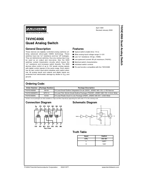
Connection Diagram
Schematic Diagram
74HC系列名词解释
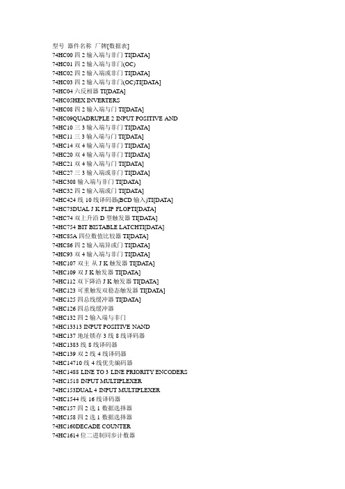
型号器件名称厂牌[数据表]74HC00四2输入端与非门TI[DA TA]74HC01四2输入端与非门(OC)74HC02四2输入端或非门TI[DA TA]74HC03四2输入端与非门(OC)TI[DATA]74HC04六反相器TI[DA TA]74HC05HEX INVERTERS74HC08四2输入端与门TI[DATA]74HC09QUADRUPLE 2-INPUT POSITIVE-AND 74HC10三3输入端与非门TI[DA TA]74HC11三3输入端与门TI[DATA]74HC14双4输入端与非门TI[DA TA]74HC20双4输入端与非门TI[DA TA]74HC21双4输入端与门TI[DATA]74HC27三3输入端或非门TI[DA TA]74HC308输入端与非门TI[DA TA]74HC32四2输入端或门TI[DATA]74HC424线-10线译码器(BCD输入)TI[DATA]74HC73DUAL J-K FLIP-FLOPTI[DATA]74HC74双上升沿D型触发器TI[DATA]74HC754-BIT BISTABLE LATCHTI[DA TA]74HC85A四位数值比较器TI[DATA]74HC86四2输入端异或门TI[DA TA]74HC93双4输入端与非门TI[DA TA]74HC107双主-从J-K触发器TI[DA TA]74HC109双J-K触发器TI[DA TA]74HC112双下降沿J-K触发器TI[DATA]74HC123可重触发双稳态触发器TI[DA TA]74HC125四总线缓冲器TI[DA TA]74HC126四总线缓冲器74HC132四2输入端与非门74HC13313-INPUT POSITIVE-NAND74HC137地址锁存3线-8线译码器74HC1383线-8线译码器74HC139双2线-4线译码器74HC14710线-4线优先编码器74HC1488-LINE TO 3-LINE PRIORITY ENCODERS 74HC1518-INPUT MULTIPLEXER74HC153DUAL 4-INPUT MULTIPLEXER74HC1544线-16线译码器74HC157四2选1数据选择器74HC158四2选1数据选择器74HC160DECADE COUNTER74HC1614位二进制同步计数器74HC162DECADE COUNTER74HC1634-BIT BINARY PRESETTABLE COUNTER 74HC1648位移位寄存器74HC1658位并行输入/串行输出寄存器74HC1668位并行输入/串行输出移位寄存器TI,PHI 74HC1734位D型寄存器TI74HC174HEX D-TYPE FLIP-FLOP WITH RESETTI 74HC175四上升沿D型触发器TI74HC190十进制同步加/减计数器TI74HC1914位二进制同步加/减计数器TI74HC192BCD二进制同步加/减计数器TI74HC193可预置4位二进制加/减计数器TI74HC1944位并入/串入-并出/串出移位寄存TI74HC1954位移位寄存器TI74HC221双单稳态触器TI74HC2373-8线译码器(带地址锁存)TI74HC2383-8线译码器TI74HC239双2-4线译码器74HC240八反相缓冲/线驱动/线接收器TI74HC241八缓冲/线驱动/线接收器TI74HC243四总线收发器TI74HC244八缓冲/线驱动/线接收器TI,FSC74HC245八双向总线发送/接发器TI,FSC74HC2518选1数据选择器74HC253双4选1数据选择器74HC257四2选1数据选择器74HC258四2选1数据选择器74HC2598位可寻址锁存器74HC266QUADRUPLE 2-INPUT EXCLUSIVE-NOR 74HC273八D触发器74HC2809位奇偶产生器/校验器TI74HC2834位二进制超位全加器74HC297DIGITAL PHASE-LOCKED-LOOP74HC2998位双向通用移位/存储寄存器74HC354带锁存三态8-1多路转换开关74HC365六总线驱动器74HC366六反相总线驱动器74HC367六总线驱动器74HC368六反相总线驱动器74HC373六D型锁存器74HC374六上升沿D型触发器74HC3754-BIT BISTABLE LATCH74HC377六上升沿D型触发器74HC3786-BIT D-TYPE FLIP-FLOP74HC379QUADRUPLE D-TYPE FLIP-FLOP74HC390双十进制计数器74HC393双4位二进制计数器74HC4002高速CMOS双4输入端或非门74HC4015高速CMOS双4位串入/并出移位寄存器74HC4016高速CMOS四传输门74HC4017高速CMOS十进制计数/分配器74HC4020高速CMOS14级串行二进制计数/分频器74HC4024高速CMOS7级二进制串行计数/分频器74HC4040高速CMOS12级二进制串行计数/分频器74HC4046A高速CMOS锁相环74HC4049高速CMOS六反相缓冲/变换器74HC4050高速CMOS六同相缓冲/变换器74HC4051高速CMOS八选一模拟开关74HC4052高速CMOS双4选1模拟开关74HC4053高速CMOS三组二路模拟开关74HC4059高速CMOS“N”分频计数器74HC4060高速CMOS14级二进制串行计数/分频器74HC406114-STAGE BINARY COUNTER/OSCILLATOR 74HC4066高速CMOS四传输门74HC4067高速CMOS16选1模拟开关74HC4075高速CMOS三3输入端或门74HC4078A8-INPUT OR/NOR74HC4094高速CMOS8位移位存储总线寄存器74HC40103高速CMOS8位可预置同步二进制减法计数器74HC40105高速CMOS先入先出FI-FD寄存器74HC423 双单稳态振荡器TI[DA TA]74HC4316高速CMOS四模拟开关TI74HC4351ANALOG MULTIPLEXER/DEMULTIPLEXERTI 74HC4352ANALOG MULTIPLEXER/DEMULTIPLEXERTI 74HC4511高速CMOSBCD锁存,7段译码,驱动器74HC4514高速CMOS4位锁存,4线-16线译码器74HC4515高速CMOS4位锁存,4线-16线译码器74HC4518高速CMOS双BCD同步加计数器74HC4520高速CMOS双4位二进制同步加计数器74HC4538高速CMOS精密双单稳TI,INT(HAR)74HC533三态八D锁存器74HC534三态八D锁存器74HC540八路三态收发缓冲器(反相)74HC541八路三态收发缓冲器(同相)74HC563三态八D锁存器74HC564三态八D锁存器74HC573四3选1数据选择器74HC574双4选1数据选择器74HC590A8位二进制计数器TI74HC5948位移位寄存器TI74HC5958位移位三态寄存器TI,ST[DATA],FSC,PHI 74HC5978位移位寄存器74HC651OCTAL BUS TRANSCEIVER/REGISTERTI 74HC652OCTAL BUS TRANSCEIVER/REGISTERTI 74HC664OCTAL BUS TRANSCEIVERTI74HC665OCTAL BUS TRANSCEIVERTI74HC6704-BY-4 REGISTER FILE74HC6828-BIT MAGNITUDE COMPARA TORS74HC6848-BIT MAGNITUDE COMPARA TORSTI74HC6888-BIT MAGNITUDE COMPARA TOR74HC7001QUADRUPLE POSITIVE-ANDTI74HC7002QUADRUPLE POSITIVE-NORTI74HC7032QUADRUPLE POSITIVE-ORTI74HC70746-SECTION MULTIFUNCTION CIRCUITTI 74HC7046A压控锁相环74HC7266QUAD 2-INPUT EXCLUSIVE-NOR GATE 74HCU04HEX INVERTERTI74HC4543高速CMOSBCD七段锁存译码,驱动器74HC47248-BIT ADDRESSABLE LATCHES74HC623OCTAL BUS TRANSCEIVERTI74HC640OCTAL BUS TRANSCEIVER74HC643OCTAL BUS TRANSCEIVERTI74HC645OCTAL BUS TRANSCEIVERTI74HC646OCTAL BUS TRANSCEIVER/REGISTER74HC648OCTAL BUS TRANSCEIVER/REGISTERTI。
74hc系列芯片
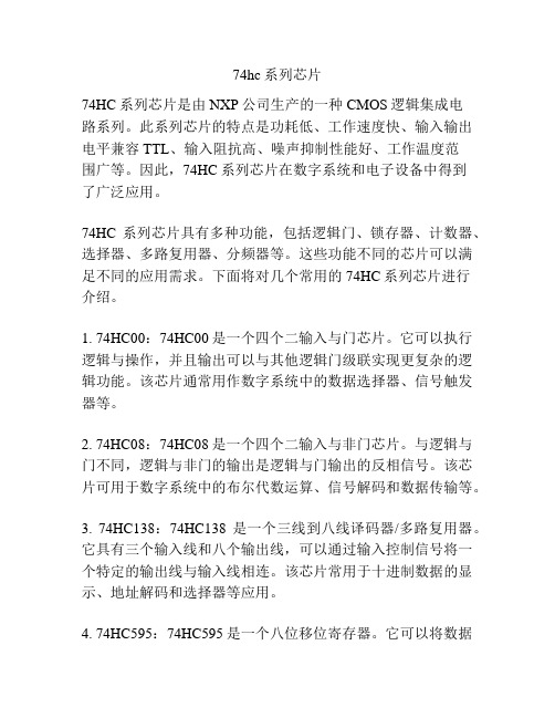
74hc系列芯片74HC系列芯片是由NXP公司生产的一种CMOS逻辑集成电路系列。
此系列芯片的特点是功耗低、工作速度快、输入输出电平兼容TTL、输入阻抗高、噪声抑制性能好、工作温度范围广等。
因此,74HC系列芯片在数字系统和电子设备中得到了广泛应用。
74HC系列芯片具有多种功能,包括逻辑门、锁存器、计数器、选择器、多路复用器、分频器等。
这些功能不同的芯片可以满足不同的应用需求。
下面将对几个常用的74HC系列芯片进行介绍。
1. 74HC00:74HC00是一个四个二输入与门芯片。
它可以执行逻辑与操作,并且输出可以与其他逻辑门级联实现更复杂的逻辑功能。
该芯片通常用作数字系统中的数据选择器、信号触发器等。
2. 74HC08:74HC08是一个四个二输入与非门芯片。
与逻辑与门不同,逻辑与非门的输出是逻辑与门输出的反相信号。
该芯片可用于数字系统中的布尔代数运算、信号解码和数据传输等。
3. 74HC138:74HC138是一个三线到八线译码器/多路复用器。
它具有三个输入线和八个输出线,可以通过输入控制信号将一个特定的输出线与输入线相连。
该芯片常用于十进制数据的显示、地址解码和选择器等应用。
4. 74HC595:74HC595是一个八位移位寄存器。
它可以将数据按照指定的顺序移位存储,并通过串行输入和并行输出的方式与其他逻辑门级联。
该芯片常用于扩展I/O端口、控制LED 显示、驱动数码管等应用。
5. 74HC4040:74HC4040是一个二进制计数器。
它具有十二个计数位和一个异步复位端口,可以按照特定的时钟信号进行二进制计数,并通过输出端口显示计数值。
该芯片广泛应用于时序控制、频率分频器等数字电路中。
除了上述常用的74HC系列芯片,还有许多其他功能的芯片,如74HC04(六个反相器)、74HC14(六个反相器带施密特触发器)等。
这些芯片以其高性能、低功耗、多功能的特点,为数字系统和电子设备的设计者提供了灵活性和便利性。
74HC系列芯片的区别
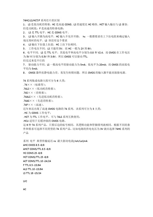
74HC/LS/HCT/F系列芯片的区别1、LS是低功耗肖特基,HC是高速COMS。
LS的速度比HC略快。
HCT输入输出与LS兼容,但是功耗低;F是高速肖特基电路;2、LS是TTL电平,HC是COMS电平。
3、LS输入开路为高电平,HC输入不允许开路,hc 一般都要求有上下拉电阻来确定输入端无效时的电平。
LS 却没有这个要求4、LS输出下拉强上拉弱,HC上拉下拉相同。
5、工作电压不同,LS只能用5V,而HC一般为2V到6V;6、电平不同。
LS是TTL电平,其低电平和高电平分别为0.8和V2.4,而CMOS在工作电压为5V时分别为0.3V和3.6V,所以CMOS可以驱动TTL,但反过来是不行的7、驱动能力不同,LS一般高电平的驱动能力为5mA,低电平为20mA;而CMOS的高低电平均为5mA;8、CMOS器件抗静电能力差,易发生栓锁问题,所以CMOS的输入脚不能直接接电源。
74系列集成电路大致可分为6大类:. 74××(标准型);.74LS××(低功耗肖特基);.74S××(肖特基);.74ALS××(先进低功耗肖特基);.74AS××(先进肖特基);.74F××(高速)。
近年来还出现了高速CMOS电路的74系列,该系列可分为3大类:. HC为COMS工作电平;. HCT为TTL工作电平,可与74LS系列互换使用;.HCU适用于无缓冲级的CMOS电路。
这9种74系列产品,只要后边的标号相同,其逻辑功能和管脚排列就相同。
根据不同的条件和要求可选择不同类型的74系列产品,比如电路的供电电压为3V就应选择74HC系列的产品系列电平典型传输延迟ns 最大驱动电流(-Ioh/Lol)mAAHC CMOS 8.5 -8/8AHCT COMS/TTL 8.5 -8/8HC COMS 25 -8/8HCT COMS/TTL 25 -8/8ACT COMS/TTL 10 -24/24F TTL 6.5 -15/64ALS TTL 10 -15/64LS TTL 18 -15/24LVCACSLC注:同型号的74系列、74HC系列、74LS系列芯片,逻辑功能上是一样的。
- 1、下载文档前请自行甄别文档内容的完整性,平台不提供额外的编辑、内容补充、找答案等附加服务。
- 2、"仅部分预览"的文档,不可在线预览部分如存在完整性等问题,可反馈申请退款(可完整预览的文档不适用该条件!)。
- 3、如文档侵犯您的权益,请联系客服反馈,我们会尽快为您处理(人工客服工作时间:9:00-18:30)。
4066
VCC(1) 7 8
11 4Y 10 4Z 9 3Z
5
2E
6
3E
GND
3Y
001aac116
12
4E
Transparent top view
(1) The die substrate is attached to this pad using conductive die attach material. It can not be used as a supply pin or input.
1 X1
1
9
10 11 12 # 1 X1
MGR256
1
10
Fig.4 IEEEC logic symbol.
2004 Nov 11
4
Philips Semiconductors
Product specification
Quad bilateral switches
74HC4066; 74HCT4066
2004 Nov 11
5
Philips Semiconductors
Product specification
Quad bilateral switches
74HC4066; 74HCT4066
RECOMMENDED OPERATING CONDITIONS 74HC4066 SYMBOL VCC VI VS Tamb PARAMETER supply voltage input voltage switch voltage ambient temperature see DC and AC characteristics per device VCC = 2.0 V VCC = 4.5 V VCC = 6.0 V VCC = 10.0 V CONDITIONS MIN. 2.0 GND GND −40 −40 − − − − TYP. 5.0 − − +25 − 6.0 − − − MAX. 10.0 VCC VCC +85 +125 1000 500 400 250 MIN. 4.5 GND GND −40 −40 − − − − TYP. 5.0 − − +25 − 6.0 − − − MAX. 5.5 VCC VCC +85 +125 500 − − − V V V °C °C ns ns ns ns 74HCT4066 UNIT
GENERAL DESCRIPTION The 74HC4066 and 74HCT4066 are high-speed Si-gate CMOS devices and are pin compatible with the HEF4066B. They are specified in compliance with JEDEC standard no. 7A. The 74HC4066 and 74HCT4066 have four independent analog switches. Each switch has two input/output pins (pins nY or nZ) and an active HIGH enable input pin (pin nE). When pin nE = LOW the belonging analog switch is turned off. The 74HC4066 and 74HCT4066 are pin compatible with the 74HC4016 and 74HCT4016 but exhibit a much lower on-resistance. In addition, the on-resistance is relatively constant over the full input signal range.
MATERIAL plastic plastic plastic plastic plastic plastic plastic plastic plastic plastic
CODE SOT27-1 SOT27-1 SOT108-1 SOT108-1 SOT337-1 SOT337-1 SOT402-1 SOT402-1 SOT762-1 SOT762-1
Product specification
Quad bilateral switches
74HC4066; 74HCT4066
FEATURES • Very low ON-resistance: – 50 Ω (typical) at VCC = 4.5 V – 45 Ω (typical) at VCC = 6.0 V – 35 Ω (typical) at VCC = 9.0 V. • Complies with JEDEC standard no. 7A • ESD protection: HBM EIA/JESD22-A114-B exceeds 2000 V MM EIA/JESD22-A115-A exceeds 200 V. • Specified from −40 °C to +85 °C and −40 °C to +125 °C.
tr, tf
input rise and fall times
LIMITING VALUES In accordance with the Absolute Maximum Rating System (IEC 60134); voltages are referenced to GND (ground = 0 V). SYMBOL VCC IIK ISK IS ICC, IGND Tstg Ptot PS Notes 1. To avoid drawing VCC current out of pin nZ, when switch current flows in pin nY, the voltage drop across the bidirectional switch must not exceed 0.4 V. If the switch current flows into pin nZ, no VCC current will flow out of pin nY. In this case there is no limit for the voltage drop across the switch, but the voltages at pins nY and nZ may not exceed VCC or GND. 2. For DIP14 packages: above 70 °C derate linearly with 12 mW/K. For SO14 packages: above 70 °C derate linearly with 8 mW/K. For SSOP14 and TSSOP16 packages: above 60 °C derate linearly with 5.5 mW/K. For DHVQFN14 packages: above 60 °C derate linearly with 4.5 mW/K. PARAMETER supply voltage input diode current switch diode current switch current VCC or GND current storage temperature power dissipation power dissipation per switch Tamb = −40 °C to +125 °C; note 2 VI < −0.5 V or VI > VCC + 0.5 V VS < −0.5 V or VS > VCC + 0.5 V −0.5 V < VO < VCC + 0.5 V; note 1 CONDITIONS MIN. −0.5 − − − − −65 − − MAX. +11.0 ±20 ±20 ±25 ±50 +150 500 100 UNIT V mA mA mA mA °C mW mW
INTEGRATED CIRCUITS
DATA SHEET
74HC4066; 74HCT4066 Quad bilateral switches
Product specification Supersedes data of 2003 Jun 17 2004 Nov 11
Philips Semiconductors
74HC4066; 74HCT4066
terminal 1 index area 1Z 2Z 2Y 2E 3E 2 3 4 5 6
14 VCC
1Y
1
handbook, halfpage
13 1E 12 4E
1Y 13 1E 1Z 2Y 2Z 3Y 3Z 4Y 4Z
MGR254
1 2 4 3 8 9 11 10
Fig.2 Pin configuration DHVQFN14.
Fig.3 Logic symbol.
handbook, halfpage handbook, halfpage
1 13 #
1 X1
1
2
1 13 # 4 5 # 8 6 # 11 12 #
MGR255
2
3
4 5 #
1 X1
1
3
9
8 6 #
handbook, halfpage
nY
13 handbook, halfpage 1E
1 1Y
5 2E
4 2Y
6 3E
8 3Y
12 4E
11 4Y nE
1Z 2
2Z 3
3Z 9
4Z 10
MGR257
VCC
