SimElectronics ——电子和机电系统的建模与仿真-推荐下载
Simscape 物理模型 汽车 HIL

Model Complexity & Detail
Configure your model to balance simulation speed and model fidelity.
14
Test Your System Efficiently
SIMULATE
Test
Computer Cluster Configure Configure Model using Simscape and add-on products Desktop System Simulation 1 Simulation 2
6
Modeling Multidomain Physical Systems
MODEL
Import
Create
SIMULATE
Test
Configure Analyze and Document
DEPLOY
Test Controller
Integrate Into Other Environments
MODEL
Import
Create
Events Logic Hydraulic, thermal, electrical, mechanial, and other physical domains
Integrate
S1 S3 S2
Modeling the controller and plant in a single environment results in optimized designs and eliminates the need for cosimulation
S
Electrical power systems
matlab2012a安装
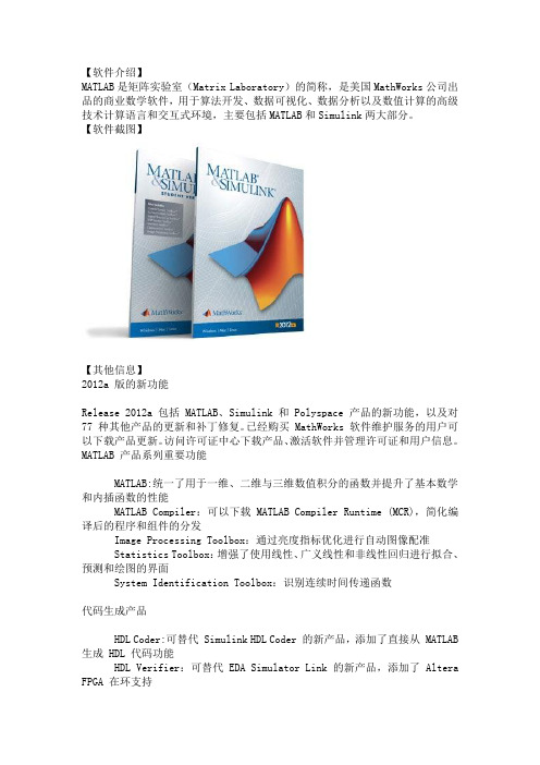
【软件介绍】MATLAB是矩阵实验室(Matrix Laboratory)的简称,是美国MathWorks公司出品的商业数学软件,用于算法开发、数据可视化、数据分析以及数值计算的高级技术计算语言和交互式环境,主要包括MATLAB和Simulink两大部分。
【软件截图】【其他信息】2012a 版的新功能Release 2012a 包括 MATLAB、Simulink 和 Polyspace 产品的新功能,以及对77 种其他产品的更新和补丁修复。
已经购买 MathWorks 软件维护服务的用户可以下载产品更新。
访问许可证中心下载产品、激活软件并管理许可证和用户信息。
MATLAB 产品系列重要功能MATLAB:统一了用于一维、二维与三维数值积分的函数并提升了基本数学和内插函数的性能MATLAB Compiler:可以下载 MATLAB Compiler Runtime (MCR),简化编译后的程序和组件的分发Image Processing Toolbox:通过亮度指标优化进行自动图像配准Statistics Toolbox:增强了使用线性、广义线性和非线性回归进行拟合、预测和绘图的界面System Identification Toolbox:识别连续时间传递函数代码生成产品HDL Coder:可替代 Simulink HDL Coder 的新产品,添加了直接从 MATLAB 生成 HDL 代码功能HDL Verifier:可替代 EDA Simulator Link 的新产品,添加了 Altera FPGA 在环支持MATLAB Coder:可从用户定义的系统对象生成代码并自动生成动态共享库 Embedded Coder:AUTOSAR 4.0 兼容性,减少了数据副本,并通过 Simulink Web 视图实现代码生成报告的链接用于在 MATLAB 和 Simulink 中进行设计的系统工具箱 (System Toolbox)Computer Vision System Toolbox:Viola-Jones 对象检测、MSER 特征检测和 CAMShift 跟踪Communications System Toolbox:USRP 无线电支持、LTE MIMO 信道模型以及 LDPC、Turbo 解码器和其他算法的 GPU 支持Simulink 产品系列重要功能Simulink:从目标硬件(包括 LEGO MINDSTORMS NXT 和 BeagleBoard)上的 Simulink 直接运行模型的能力SimMechanics:具有新的三维可视化功能的第二代多体建模和仿真技术Real-Time Windows Target:使用 Simulink 标准模式实时执行 Windows 中的模型官方说明:/products/new_products/latest_features.html产品列表:R2012a Product and Platform ListMATLAB 7.14 - win32 win64Simulink 7.9 - win32 win64Aerospace Blockset 3.9 - win32 win64Aerospace Toolbox 2.9 - win32 win64Bioinformatics Toolbox 4.1 - win32 win64Communications System Toolbox 5.2 - win32 win64Computer Vision System Toolbox 5.0 - win32 win64Control System Toolbox 9.3 - win32 win64Curve Fitting Toolbox 3.2.1 - win32 win64DO Qualification Kit 1.6 - win32 win64DSP System Toolbox 8.2 - win32 win64Data Acquisition Toolbox 3.1 - win32 win64Database Toolbox 3.11 - win32 win64Datafeed Toolbox 4.3 - win32 win64Econometrics Toolbox 2.1 - win32 win64Embedded Coder 6.2 - win32 win64Filter Design HDL Coder 2.9.1 - win32 win64Financial Derivatives Toolbox 5.9 - win32 win64Financial Toolbox 4.2 - win32 win64Fixed-Income Toolbox 2.3 - win32 win64Fixed-Point Toolbox 3.5 - win32 win64Fuzzy Logic Toolbox 2.2.15 - win32 win64Gauges Blockset 2.0.6 - win32Global Optimization Toolbox 3.2.1 - win32 win64HDL Coder 3.0 - win32 win64HDL Verifier 4.0 - win32 win64IEC Certification Kit 2.1 - win32 win64Image Acquisition Toolbox 4.3 - win32 win64Image Processing Toolbox 8.0 - win32 win64Instrument Control Toolbox 3.1 - win32 win64MATLAB Builder EX 2.2 - win32 win64MATLAB Builder JA 2.2.4 - win32 win64MATLAB Builder NE 4.1.1 - win32 win64MATLAB Coder 2.2 - win32 win64MATLAB Compiler 4.17 - win32 win64MATLAB Distributed Computing Server 6.0 - win32 win64 MATLAB Report Generator 3.12 - win32 win64Mapping Toolbox 3.5 - win32 win64Model Predictive Control Toolbox 4.1 - win32 win64Model-Based Calibration Toolbox 4.4 - win32 win64Neural Network Toolbox 7.0.3 - win32 win64OPC Toolbox 3.1.1 - win32 win64Optimization Toolbox 6.2 - win32 win64Parallel Computing Toolbox 6.0 - win32 win64Partial Differential Equation Toolbox 1.0.20 - win32 win64 Phased Array System Toolbox 1.2 - win32 win64RF Toolbox 2.10 - win32 win64Real-Time Windows Target 4.0 - win32 win64Robust Control Toolbox 4.1 - win32 win64Signal Processing Toolbox 6.17 - win32 win64SimBiology 4.1 - win32 win64SimDriveline 2.2 - win32 win64SimElectronics 2.1 - win32 win64SimEvents 4.1 - win32 win64SimHydraulics 1.10.1 - win32 win64SimMechanics 4.0 - win32 win64SimPowerSystems 5.6 - win32 win64SimRF 3.2 - win32 win64Simscape 3.7 - win32 win64Simulink 3D Animation 6.1 - win32 win64Simulink Code Inspector 1.1 - win32 win64Simulink Coder 8.2 - win32 win64Simulink Control Design 3.5 - win32 win64Simulink Design Optimization 2.1 - win32 win64Simulink Design Verifier 2.2 - win32 win64Simulink Fixed Point 7.1 - win32 win64Simulink PLC Coder 1.3 - win32 win64Simulink Report Generator 3.12 - win32 win64Simulink Verification and Validation 3.3 - win32 win64 Spreadsheet Link EX 3.1.5 - win32 win64Stateflow 7.9 - win32 win64Statistics Toolbox 8.0 - win32 win64Symbolic Math Toolbox 5.8 - win32 win64System Identification Toolbox 8.0 - win32 win64SystemTest 2.6.3 - win32 win64Vehicle Network Toolbox 1.6 - win32 win64Wavelet Toolbox 4.9 - win32 win64xPC Target 5.2 - win32 win64xPC Target Embedded Option 5.2 - win32 win64附带安装过程:1.选择不适用Internet安装;附带安装过程:1.选择不适用Internet安装;2.同意许可;3.填入安装密钥(见crack文件夹中install.txt);4.选择安装类型(建议选择自定义,选择典型之后可能导致开始菜单和桌面上安装之后没有快捷方式,如果你遇到了这个情况,解决方法见后,这里我选择了典型,所以遇到了前述问题);5.等待安装完成;6.运行Matlab,第一次运行时,它会要求你激活,选择crack文件夹中的lic_standalone.dat;7.激活成功;8.运行Matlab,成功;9.如果你想更改Matlab默认的工作目录的话,请更改快捷方式上的起始位置(如图);10.如果你不幸遇到了第四条中的问题,那么,Matlab在<安装目录>\MATLAB\R2012a\bin\win32中。
MATLAB产品介绍

MATLAB –基于模型设计仿真平台MATLAB是美国MathWorks公司开发用于解决科学计算和动态系统建模仿真的软件包,经过20多年的发展,MATLAB已经成为科学计算、控制系统设计与仿真、信号处理设计与仿真等领域的事实上的工业标准工具,被广泛应用于航空航天与国防、汽车、教育、行政等行业。
世界各大知名航空航天与国防单位普遍使用MA TLAB作为平台化的工具进行基于模型的设计,比如Lockheed Martin F-35战斗机、NASA火星探测器等。
MA TLAB为多领域系统设计提供了统一的软件环境,能够进行高性能动态系统的仿真、分析及测试,并能自动生成符合DO-178B 和MISRA-C标准的高效的嵌入式代码,为开发人员提供一体化工作平台。
“不远的将来,每个工程师的计算机上有两个必用的应用软件,一个是微软的Word, 一个是MATLAB。
”--The Mathworks公司总裁Jack LittleMATLAB软件包由同名的MATLAB®基础模块、Simulink®基础模块和其他90多个各应用领域的产品模块(toolbox\Blockset等)所共同组成。
MATLAB –科学计算的语言MATLAB作为科学计算领域的首选工具,提供了基于矩阵的数值计算功能,集成了2维和3维图形能力,拥有方便的图形用户界面设计能力,并提供了一种交互式的高级编程语言—M语言,这种语言比C/C++、Fortran等语言更适合解决科学和技术问题。
用户可以通过编写M语言脚本或者函数文件进行高效的数据分析、可视化和算法开发工作。
MathWorks公司利用M语言开发了涉及各个专业领域解决实际应用问题的丰富的工具箱,扩展了控制系统设计与分析、信号和图像处理、金融财务分析等领域;工具箱还提供数据采集和处理功能,MATLAB可以直接获取硬件设备(串口、网口、声卡、显卡和其他工控机板卡等)和软件(数据库、文本、Excel等)的测试测量数据,同时,MATLAB提供了统计、曲线拟合、优化等工具箱对数据进行综合处理与分析。
光伏电池阵列模型的 Matlab 设计与仿真
光伏电池阵列模型的 Matlab 设计与仿真余基映;张腾;谭兴毅【摘要】利用 Matlab 软件平台搭建了光伏电池阵列的仿真电路模型,研究了光照因素、温度因素及光伏电池内部参数对光伏阵列电气特性的影响,并针对动态光照条件下光伏阵列的输出特性进行仿真和计算。
研究结果表明:光照强度、温度和串联电阻的变化对光伏阵列开路电压、短路电流、伏安特性、输出功率及最佳工作点具有显著影响,光伏阵列的仿真模型可以较好实现光伏阵列的动态仿真。
%A circuit simulation model of photovoltaic array was developed based on Matlab / Simulink soft-ware,the effects of solar insolation,temperature and photovoltaic cell parameters on electrical behavior of photovoltaic array were analyzed,and the output characteristics of photovoltaic array under dynamic irra-diance condition were simulated and calculated. The simulation results indicated that irradiance,tempera-ture and series resistor have significant impact on open-curcuit voltage,short-circuit current,volt-am-pere characteristic,output power and optimum working point of photovoltaic array. The developed model is capable of accomplishing dynamic simulation of photovoltaic array.【期刊名称】《湖北民族学院学报(自然科学版)》【年(卷),期】2016(034)001【总页数】4页(P64-67)【关键词】光伏电池阵列;仿真;输出特性【作者】余基映;张腾;谭兴毅【作者单位】湖北民族学院科技学院,湖北恩施 445000;湖北民族学院理学院,湖北恩施 445000;湖北民族学院理学院,湖北恩施 445000【正文语种】中文【中图分类】TM914光伏发电技术是基于光伏效应实现太阳能转化为电能的发电方式,目前已被广泛应用于太空卫星、电信基站及偏远山区等领域,并逐步成为解决未来能源危机和生态环境问题的有效途径[1-5].光伏阵列作为电能供应装置是构成光伏系统的核心部件,其输出特性的研究对于提高太阳能利用效率和光伏发电系统输出功率具有关键性作用.利用计算机技术建立光伏阵列仿真模型可以方便地模拟和评估不同光照及温度条件任意排列方式光伏阵列的输出电气特性,具有很好的实用价值和应用前景.Matlab软件因具有高效的计算性能而备受国内外研究者青睐,被广泛应用于光伏系统的设计和性能仿真研究[6-9].目前,普遍采用单二极管等效电路模型来建立光伏电池仿真模型[10-13],该等效电路模型由线性直流源和单个二极管并联组成,没有考虑半导体耗尽层中因能量激发所产生电子恢复运动[14],因而欠缺通用性.本文基于双二极管等效电路模型[15]建立光伏电池单体模型,增加的二极管用来等效光伏电池漏电流特性,可以提升仿真效率和计算精度.利用Matlab软件仿真模块simElectronics组件库搭建光伏阵列物理特性的通用仿真模型,该仿真模型以光照强度、环境温度及光伏电池内部参数为输入条件,仿真得到光伏阵列的输出V-I特性和V-P特性.通过模拟变化的光照条件,得到光伏阵列输出电气特性的动态仿真结果.双二极管等效电路模型如图1所示,因此,输出电流I满足式(1),其中Iph为光生电流,Rs、Rp表示光伏电池等效串联电阻、并联电阻,N1、N2代表二极管D1、D2理想因子,Is1、Is2代表二极管D1、D2反向饱和电流,Vt表示光伏电池热电压,满足:Vt = kT/q,k为波尔兹曼常量,q为元电荷,T为光伏电池温度.在Matlab/Simulink环境下搭建光伏阵列仿真模型如图2所示,光伏阵列由36块光伏电池单体组成,图3给出了光伏阵列子系统中各模块连接方式.光伏阵列由6个光伏组件构成,每个光伏组件由6个光伏电池串联而成,光伏阵列的光照条件参数由Signal Builder模拟产生,光伏电池单体模型基于双二极管等效电路模型建立,仿真计算过程采用变步长Ode45(Dormand-Prince)算法,仿真运行速度快.2.1 光伏阵列光照及温度特性仿真设定光伏电池仿真参数如表1所示,在环境温度为25℃条件下,改变光照强度Ir 值分别为0.25、0.75和1.25 kW/m2得到光伏阵列V-I和V-P特性曲线如图4所示,表2列出光伏阵列不同光照强度时开路电压Voc、短路电流Isc及最大输出功率Pm等参数.由图4可以看出,随着光强增大,短路电流Isc和开路电压Voc 增大,光伏阵列输出电流与输出功率显著上升,这是由于光强增加有利于提高光伏电池内部载流子迁移率及光子吸收系数[16],从而提升光伏阵列转换效率.固定光照强度值为1 kW/m2,得到温度T分别为15℃、25℃和35℃时光伏阵列V-I和V-P特性曲线如图5所示,表3列出了不同温度时光伏阵列的输出特性参数.由图5可得,不同温度下光伏阵列短路电流Isc基本不变,可见光生电流受温度因素影响较小.随着温度升高,光伏阵列输出电流与输出功率明显下降,其中开路电压Voc和最大输出功率Pm同时减小,该仿真结果与文献[17]中光伏电池温度特性的实验研究结果基本一致.从不同条件下的仿真结果可以看出,光照强度和温度与光伏阵列的输出电气特性密切相关,随着光强和温度的变化,最大功率点(Um,Pm)发生明显改变.由表3和表4仿真数据结果可见,光强值变化量为500 W时,最佳工作电压Um值平均变化幅度约为0.19 V,温度变化量为10℃时,最佳工作电压Um值变化平均幅度约为1.33 V,可见,温度改变对最佳工作点(Um,Im)影响较大.该仿真结果可应用于光伏系统中最佳工作点跟踪技术[18-20],实际光伏系统中可根据外部环境变化来实时调整光伏阵列工作点以满足负载需求.2.2 串联电阻对光伏阵列输出特性的影响按照表1设定的仿真参数,改变光伏电池组件串联电阻Rs大小依次为:0.01、0.025和0.05 时,光伏阵列输出特性参数、V-I特性及V-P特性曲线分别如表4和图6所示,可见,光伏电池串联电阻影响光伏阵列输出伏安特性和输出功率.从仿真结果可以看出,串联电阻增大时光伏阵列输出电流和输出功率降低,且伏安特性曲线由非线性关系变为线性关系,短路电流Is值呈现减小趋势,开路电压Voc基本不变,最佳工作点(Um,Im)位置变化明显,最大输出功率Pm随串联电阻减小而增大.因此,针对光伏电池的生产工艺而言,较低的串联电阻更有利于提升光伏阵列的输出功率和光伏转换效率[21].2.3 光伏阵列动态仿真设定温度为25 C,光伏阵列其它参数的设定参照表1,采用自定义的函数来模拟光照条件的变化,图7(a)给出光伏阵列光照强度随时间的变化情况,光照强度值变化依次为:0.75、0. 5、1、0.25、1.25 kW/m2.仿真得到光伏阵列的输出电压、输出电流和输出功率的变化曲线如图7(b)(d)所示,光照强度值发生变化时光伏阵列的响应时间依次为:8.6×10-3 、8.4×10⁻³ 、9.9×10⁻³ 、6.3×10⁻³ s.因此,该模型能够快速有效地模拟光照条件变化时光伏阵列输出电压、输出电流和输出功率的动态特性,可应用于实际光伏系统的工程设计.通过搭建光伏电池阵列的Matlab通用仿真电路模型,得到了不同条件下光伏阵列的输出电气参数,研究了光伏阵列的光照特性和温度特性,并对光伏阵列进行了动态模拟仿真.研究结果表明:光伏阵列的输出电流、输出功率与光照强度呈正相关,与温度呈负相关.短路电流和开路电压随光照强度增强而增大,温度的变化对光伏阵列短路电流无明显影响,开路电压随温度升高而减小,温度和串联电阻对光伏阵列最佳工作点影响较为显著.光伏阵列的Matlab仿真模型仿真速度快,输出特性与实际光伏阵列特性基本一致,能够动态模拟仿真外部光照条件变化时光伏阵列输出的电气特性,可为实际光伏系统的理论研究和工程应用提供平台.。
MEMS原理解读

什么是MEMS?
• MEMS是英文Micro Electro Mechanical systems的缩写,即微 电子机械系统。微电子机械系统(MEMS)技术是建立在微米/纳 米技术(micro/nanotechnology)基础上的21世纪前沿技术, 是指对微米/纳米材料进行设计、加工、制造、测量和控制的技 术。它可将机械构件、光学系统、驱动部件、电控系统集成为一 个整体单元的微型系统。这种 微电子机械系统不仅能够采集、 处理与发送信息或指令,还能够按照所获取的信息自主地或根据 外部的指令采取行动。它用微电子技术和微加工技术(包括硅体 微加工、硅表面微加工、LIGA和晶片键合等技术)相结合的制造 工艺,制造出各种性能优异、价格低廉、微型化的传感器、执行 器、驱动器和微系统。 微电子机械系统(MEMS)是近年来发 展起来的一种新型多学科交叉的技术,该技术将对未来人类生活 产生革命性的影响。它涉及机械、电子、化学、物理、光学、生 物、材料等多学科。
Materials for MEMS Manufacturing
• Silicon • Polymers [ˈpɔlimə] • Metals
MEMS Basic Processes
• This chart is not complete:
Basic Process
Deposition
Patterning
MEMS description
• MEMS technology can be implemented using a number of different materials and manufacturing techniques; the choice of which will depend on the device being created and the market sector in which it has to operate.
控制系统仿真第6章 电力电子及电机拖动系统的simscape仿真

该对话框分为上下两部分:上部分为仿 真参数设置对话框,下部分为powergui 提供的一系列分析工具。
“Steady-State Voltage and Currents”: 显示模型中稳态电压和电流 “Initial State Settings”:显示和修改初 始状态 “Load Flow” “Machine Initialization”: 用于执行潮流和电机初始化
在参数设置中,将其类型设置为6脉冲发生器,勾选 触发方式为“双脉冲触发”(Double pulsing)。在双 脉冲触发方式时,下一个晶闸管触发的同时给前一 个晶闸管补一个脉冲,以保证在电流断续时,整流 器上下桥臂都各有一个晶闸管同时导通。该模块输 入端有3个:alpha控制移相角的大小,单位为度; wt端输入同步信号,一般由锁相回路(PLL)产生; block端是控制端口,如果输入block的值大于零, 则输出被禁止。
启动仿真之后,双击 powergui模块,单击 其中的FFT Analysis分 析工具,即可打开FFT 分析窗口。
单相不可控整流电路 直流侧电容两端的电 压以直流成分为主, 但是含有50Hz, 100Hz,200Hz, 300Hz等主要谐波成 分。
6.2 三相桥式全控整流电路的Simscape仿真
“Use LTI Viewer”:启动控制系统工具箱 中线性时不变系统分析工具的LTI浏览器
“Impedance vs Frequency Measurement”:显示阻抗-频率测量值
“FFT Analysis”:快速傅里叶分析
Matlab工具箱中英文对照
Matlab2010工具箱中英文对照matlab distributed computing server 分布式计算服务器simulink 仿真aerospace blockset 航天模块集aerospace toolbox 航天工具箱bioinformatics toolbox 生物信息学工具箱communications blockset 通信模块集communications toolbox 通信工具箱control system toolbox 控制系统工具箱curve fitting toolbox 曲线拟合工具箱data acquisition toolbox 数据采集工作箱database toolbox 数据库工作箱data feed toolbox 数据传送工具箱DO qualification kit 鉴定工具包Econometrics toolbox 计量经济学工具箱EDA simulator link 电子设计自动化模拟器连接Embedded IDE link 嵌入式集成电路设备连接Filter design HDL coder 滤波器设计HDL编码器Filter design toolbox 滤波器设计工具箱Financial derivatives toolbox 金融衍生工具箱Financial toolbox 财经工具箱Fixed-income toolbox 固定输入工具箱Fixed-point toolbox 定点工具箱Fuzzy logic toolbox 模糊逻辑工具箱Gauges blockset 仪表工具箱Global optimization toolbox全域最佳化IEC certification kit 组织认定工具包Image acquisition toolbox 图像采集工具箱Image processing toolbox 图像处理工具箱Instrument control toolbox仪器控制工具箱Mapping toolbox 地图工具箱Matlab builder EX excel的matlab生成器Matlab builder JA java的matlab生成器Matlab builder NE net的matlab生成器Matlab compiler matlab编译器Matlab report generator matlab报告生成器Model predictive control toolbox 模型预测控制工具箱Model –based calibration toolbox 模型校正工具箱Neural network toolbox 神经网络工具箱OPC toolbox OPC工具箱Optimization toolbox 优化工具箱Parallel computing toolbox 并行计算工具箱Partial differential equation toolbox 偏微分方程工具箱Real-time windows target 实时windows目标Real-time workshop embedded coder 实时工作空间内置编码器RF toolbox RF工具箱Robust control toolbox 鲁棒控制工具箱Signal processing blockset 型号处理模块集Signal processing toolbox 型号处理工具箱Simbiology 仿真生物Simdriveline 仿真驱动链接Simelectronics 仿真电子学Simevents 仿真事件Simhydraulic 仿真液压Simmechanics 仿真力学Simpowersystem 仿真动力系统SimRF 仿真RFSimscape 仿真场景Simulink 3D animation 3D动画仿真Simulink control design 控制设计仿真Simulink design optimization 设计优化仿真Simulink design verifier 设计校正仿真Simulink fixed point 定点仿真Simulink HDL coder HDL编码器仿真Simulink PLC coder PLC编码器仿真Simulink report generator 报告生成器仿真Simulink verification and validation 仿真检验与确认Spreadsheet link EX excel电子表格连接State flow 状态流State flow coder 状态流编码器Statistics toolbox 统计工具箱Symbolic math toolbox 符号数学工具箱System identification toolbox 系统识别工具箱System test 系统测试Target support package 目标支持工具包Vehicle network toolbox 运载网络工具箱Video and image processing blockset 视频和图像处理模块集Wavelet toolbox 小波工具箱xPC target xPC目标xPC target embedded option xPC目标嵌入选择。
工程系统建模与仿真

第7章 工程系统建模与仿真
更复杂的工程系统当然可以从底层建模, 但非专业人士很难建模,可以采用现成专 业工具直接建模仿真 建模方便、仿真结果可靠 主要内容
物理系统建模仿真模块集Simscape简介 电气系统模块集简介 电子线路及其仿真 电机与拖动系统仿真 机械系统建模与仿真
Friday, 2010-10- 8, 07:11:15 第7章:工程系统建模与仿真 薛定宇、陈阳泉《基于MATLAB/Simulink的系统仿真技术与应用》清华大学出版社2010
PS-Simulink Converter Simulink-PS Converter
仿真参数设置模块、双向连接模块和连接 端口模块
Friday, 2010-10- 8, 07:11:15 第7章:工程系统建模与仿真 薛定宇、陈阳泉《基于MATLAB/Simulink的系统仿真技术与应用》清华大学出版社2010
Simscape语言描述的模型步骤
引导语句:由component、domain关键词引导 对话框参数定义语句:用parameters模块定义该模块 对话框变量参数和物理量单位,要求用户输入这4 个参数及其单位。 变量声明语句:由variables关键词引导 初始设置与参数验证子函数:function setup首先检 测输入的变量值是不是正数,如果不是则给出错误 信息。 模型方程定义:由equations引导,描述数学方程
电路建模与仿真
电路图 Simulink模型 c7mele1.mdl 数值解和解析解 的比较
Friday, 2010-10- 8, 07:11:15
第7章:工程系统建模与仿真 薛定宇、陈阳泉《基于MATLAB/Simulink的系统仿真技术与应用》清华大学出版社2010
薛定谔—麦克斯韦尔方程径向解的存在性和多重性(英文)

In 1887, the German physicist Erwin Schrödinger proposed a radial solution to the Maxwell-Schrödinger equation. This equation describes the behavior of an electron in an atom and is used to calculate its energy levels. The radial solution was found to be valid for all values of angular momentum quantum number l, which means that it can describe any type of atomic orbital.The existence and multiplicity of this radial solution has been studied extensively since then. It has been shown that there are infinitely many solutions for each value of l, with each one corresponding to a different energy level. Furthermore, these solutions can be divided into two categories: bound states and scattering states. Bound states have negative energies and correspond to electrons that are trapped within the atom; scattering states have positive energies and correspond to electrons that escape from the atom after being excited by external radiation or collisions with other particles.The existence and multiplicity of these solutions is important because they provide insight into how atoms interact with their environment through electromagnetic radiation or collisions with other particles. They also help us understand why certain elements form molecules when combined together, as well as why some elements remain stable while others decay over time due to radioactive processes such as alpha decay or beta decay.。
MATLAB2014a安装说明中英文转换
MATLAB®是一种用于数值计算、可视化及编程的高级语言和交互式环境。
使用MATLAB,可以分析数据,开发算法,创建模型和应用程序。
借助其语言、工具和内置数学函数,您可以探求多种方法,比电子表格或传统编程语言(如C/C++ 或Java™)更快地求取结果。
MATLAB 应用广泛,其中包括信号处理和通信、图像和视频处理、控制系统、测试和测量、计算金融学及计算生物学等众多应用领域。
在各行业和学术机构中,有一百多万工程师和科学家使用MATLAB 这一技术计算语言.【软件截图】Matlab R2014a【其他信息】新增功能概览R2014a ( 版本8.3) - 发行时间2014年3月7日MATLAB 产品系列MATLAB®:Raspberry Pi 和网络摄像头硬件支持包Optimization Toolbox™: 混合整数线性规划(MILP) 求解器Statistics Toolbox™: 使用每个主题的多个测量值反复测量数据建模Image Processing Toolbox™: 使用MATLAB Coder™ 为25 个函数生成C 代码,为5 个函数增加了GPU加速功能Econometrics Toolbox™: 状态空间模型、缺失数据情况下自校准的卡尔曼滤波器以及ARIMA/GARCH 模型性能增强Financial Instruments Toolbox™: 对偶曲线构建,用于计算信用敞口和敞口概况的函数,以及利率上限、利率下限和掉期期权的布莱克模型定价SimBiology®: 提供用于模型开发的模型估算和桌面增强的统一函数System Identification Toolbox™: 递归最小二乘估算器和在线模型参数估算模块MATLAB Production Server™:实现客户端与服务器之间的安全通讯以及动态请求创建Simulink 产品系列Simulink®: 用于定义和管理与模型关联的设计数据的数据字典Simulink: 用于算法分割和用于多核处理器及FPGA目标器件的单一模型工作流程Simulink:为LEGO MINDSTORMS EV3、Arduino Due 和Samsung Galaxy Android 设备提供内建支持Stateflow®: 在Stateflow 状态图中填写上下文相关的选项卡Simulink Real-Time™: 仪表板、高分辨率目标显示器和FlexRay 协议支持,以及合并了xPC Target™ 和xPC Target Embedded Option™ 的功能SimMechanics™: STEP 文件导入和接头的总约束力计算Simulink® Report Generator™: 用于在Simulink Web view视图中丰富显示内容的对象检查器和通知程序用于在MATLAB 和Simulink 中进行设计的系统工具箱(System Toolbox)Co mputer Vision System Toolbox™: 立体视觉和光学特性识别(OCR) 函数LTE System Toolbox™: 一款新产品,可用于LTE和LTE-Advanced无线通讯系统的物理层仿真代码生成和实现Embedded Coder®: 将AUTOSAR 工具的变更合并到Simulink 模型中Embedded Coder: ARM Cortex-A 使用Ne10 库优化了代码生成HDL Coder™: 支持枚举数据类型和时钟频率驱动的自动流水线操作HDL Verifier™: 使用JTAG对Altera®硬件进行FPGA在环仿真包含组件代码-----------------------------------------------------------------------------------------------MATLAB 版本: 8.3.0.532 (R2014a)MATLAB 许可证编号: 271828操作系统: Microsoft Windows 7 专业版Version 6.1 (Build 7601: Service Pack 1)Java 版本: Java 1.7.0_11-b21 with Oracle Corporation Java HotSpot(TM) 64-Bit Server VM mixed mode -----------------------------------------------------------------------------------------------MATLAB 版本8.3 (R2014a)Simulink 版本8.3 (R2014a)Aerospace Blockset 版本3.13 (R2014a)Aerospace Toolbox 版本2.13 (R2014a)Bioinformatics Toolbox 版本4.4 (R2014a)Communications System Toolbox 版本5.6 (R2014a)Computer Vision System Toolbox 版本6.0 (R2014a)Control System Toolbox 版本9.7 (R2014a)Curve Fitting Toolbox 版本3.4.1 (R2014a)DO Qualification Kit 版本2.3 (R2014a)DSP System Toolbox 版本8.6 (R2014a)Data Acquisition Toolbox 版本3.5 (R2014a)Database Toolbox 版本5.1 (R2014a)Datafeed Toolbox 版本4.7 (R2014a)Econometrics Toolbox 版本3.0 (R2014a)Embedded Coder 版本6.6 (R2014a)Filter Design HDL Coder 版本2.9.5 (R2014a) Financial Instruments Toolbox 版本1.3 (R2014a) Financial Toolbox 版本5.3 (R2014a)Fixed-Point Designer 版本4.2 (R2014a)Fuzzy Logic Toolbox 版本2.2.19 (R2014a)Global Optimization Toolbox 版本3.2.5 (R2014a) HDL Coder 版本3.4 (R2014a)HDL Verifier 版本4.4 (R2014a)IEC Certification Kit 版本3.3 (R2014a)Image Acquisition Toolbox 版本4.7 (R2014a)Image Processing Toolbox 版本9.0 (R2014a) Instrument Control Toolbox 版本3.5 (R2014a)LTE System Toolbox 版本1.1 (R2014a)MATLAB Builder EX 版本2.5 (R2014a)MATLAB Builder JA 版本2.3.1 (R2014a)MATLAB Builder NE 版本4.2.1 (R2014a)MATLAB Coder 版本2.6 (R2014a)MATLAB Compiler 版本5.1 (R2014a)MATLAB Report Generator 版本3.16 (R2014a) Mapping Toolbox 版本4.0.1 (R2014a)Model Predictive Control Toolbox 版本4.2 (R2014a) Model-Based Calibration Toolbox 版本4.7 (R2014a) Neural Network Toolbox 版本8.2 (R2014a)OPC Toolbox 版本3.3.1 (R2014a)Optimization Toolbox 版本7.0 (R2014a)Parallel Computing Toolbox 版本6.4 (R2014a) Partial Differential Equation Toolbox 版本1.4 (R2014a) Phased Array System Toolbox 版本2.2 (R2014a) Polyspace Bug Finder 版本1.1 (R2014a)Polyspace Code Prover 版本9.1 (R2014a)RF Toolbox 版本2.14 (R2014a)Real-Time Windows Target 版本4.4 (R2014a) Robust Control Toolbox 版本5.1 (R2014a)Signal Processing Toolbox 版本6.21 (R2014a) SimBiology 版本5.0 (R2014a)SimDriveline 版本2.6 (R2014a)SimElectronics 版本2.5 (R2014a)SimEvents 版本4.3.2 (R2014a)SimHydraulics 版本1.14 (R2014a)SimMechanics 版本4.4 (R2014a) SimPowerSystems 版本6.1 (R2014a)SimRF 版本4.2 (R2014a)Simscape 版本3.11 (R2014a)Simulink 3D Animation 版本7.1 (R2014a)Simulink Code Inspector 版本2.1 (R2014a)Simulink Coder 版本8.6 (R2014a)Simulink Control Design 版本4.0 (R2014a)Simulink Design Optimization 版本2.5 (R2014a)Simulink Design Verifier 版本2.6 (R2014a)Simulink PLC Coder 版本1.7 (R2014a)Simulink Real-Time 版本6.0 (R2014a)Simulink Report Generator 版本3.16 (R2014a)Simulink Verification and Validation 版本3.7 (R2014a) Spreadsheet Link EX 版本3.2.1 (R2014a)Stateflow 版本8.3 (R2014a)Statistics Toolbox 版本9.0 (R2014a)Symbolic Math Toolbox 版本6.0 (R2014a)System Identification Toolbox 版本9.0 (R2014a)SystemTest 版本2.6.7 (R2014a)Trading Toolbox 版本2.1 (R2014a)Vehicle Network Toolbox 版本2.2 (R2014a)Wavelet Toolbox 版本4.13 (R2014a)!mcc输出结果代码MCC Invoke MATLAB to C/C++ Compiler (Version 5.1).MCC [-options] fun [fun2 ...]Prepare fun.m for deployment outside of the MATLAB environment. Generate wrapper files in C or C++ and optionally build standalone binary files.Write any resulting files into the current directory, by default.For all targets except standalone, if more than one file is specified, a C or C++ interface is generated for each file.The only exception to this rule is when the file is specifiedwith a '-a' flag.If C or object files are specified, they are passed to MBUILD along with any generated C files.If conflicting options are presented to MCC, the rightmost conflictingoption is used.OPTIONS:a <filename> Add <filename> to the CTF archive. If the specified fileis an M, mex or p file, this function will not be exported in the resulting target.b Generate an MS Excel compatible formula function for thegiven list of MATLAB functions (requires MATLAB Builder EX). This option will be removed in a future release of MATLAB Builder for EX.B <filename>[:<arg>[,<arg>]] Specify bundle file. <filename> is a text file containing Compiler command line options. The Compiler behaves as if the "-B <filename>" were replaced by the contents of thebundle file. Newlines appearing in these files are allowed and are treated as whitespace. MathWorks provides options files for the following:ccom Used for building COM components on Windows(requires MATLAB Builder NE)cexcel Used for building Excel components on Windows(requires MATLAB Builder EX installed)cjava Used for building Java components (requiresMATLAB Builder JA installed)cpplib Used for building a C++ shared library.csharedlib Used for building a C shared library.dotnet Used for building .NET components on Windows(requires MATLAB Builder NE installed)C For stand-alone applications and shared libraries, generate a separate CTF archive. If this option is not specified, the CTF will be embedded within the stand-alone application or library.c C only. Generate C wrapper code. This is equivalent to "-T codegen" as the rightmost argument on the command line.d <directory> Output directory. All generated files will be put in<directory>.e Macro that generates a C Windows application on the Windows platform. On non-Windows platforms, it is the same as the macro -m. This isequivalent to the options "-W WinMain -T link:exe", which can be foundin the file <MATLAB>/toolbox/compiler/bundles/macro_option_e.f <filename> Override the default options file with the specifiedoptions file when calling MBUILD. This allows you to use differentANSI compilers. This option is a direct pass-through to the MBUILDscript. See "External Interfaces" documentation for moreinformation.g Debug. Include debugging symbol information.I <path> Include path. Add <path> to the list of paths to search forfiles. The MATLAB path is automatically included when runningfrom MATLAB. When running from DOS or the UNIX shell, theMATLAB Compiler includes the paths from pathdef.m in<matlabroot>/toolbox/local.l Create function library. This option is equivalent to -W lib-T link:lib. It generates library wrapper functions for each fileon the command line and calls your C compiler to build a sharedlibrary, which exports these functions. The library name is thecomponent name, which is either derived from the name of the firstfile on the command line or specified with the -n option.m Macro that generates a C stand-alone application. This isequivalent to the options "-W main -T link:exe", which can be foundin the file <MATLAB>/toolbox/compiler/bundles/macro_option_m.M "<string>" Pass <string> to the MBUILD script to build an executable. If -M is used multiple times, the rightmost occurrenceis used.N Clear path. Clear the compilation search path of all directoriesexcept the following core directories:<matlabroot>/toolbox/matlab<matlabroot>/toolbox/local<matlabroot>/toolbox/compiler<matlabroot>/toolbox/javabuilder for building Java components<matlabroot>/toolbox/dotnetbuilder for building .NET componentsIt also retains all subdirectories of the above list that appear onthe MATLAB path at compile time.o <outputfilename> Output name. Set the name of the final component and CTF archive to <outputfilename>. A suitable, possiblyplatform-dependent, extension is added to <outputfilename> (e.g.,".exe" for Windows stand-alone applications). The default outputfilename is the name of the first file (for stand-alone target)or the name specified with the -W option. See option W for more information.p <directory> Add <directory> to the compilation search path. Thisoption can only be used in conjunction with the -N option. Thisoption will add <directory> to the compilation search path in thesame order as in your MATLAB path. If directory is not an absolutepath, it is assumed to be under the current working directory. Therules for how these directories are included are* If <directory> is on the original MATLAB path, the <directory>and all its subdirectories that appear on the original path areadded to the compilation search path in the same order as itappears on MATLAB path.* If <directory> is not on the original MATLAB path, it is notincluded in the compilation. (You can use -I to add it.)If the same directory is added with both the -I and -p option (-N appearing before both the options), the directory will be added asper the rules of -p.R <option> Specify the run-time options for the MATLAB Common Runtime (MCR) usage:Supported MCR options are -nojvm, -nodisplay (UNIX ony) and -logfile.The -logfile option should always be followed by the name of the logfile.EXAMPLES:mcc -e -R '-logfile,bar.txt' -v foo.mmcc -m -R -nojvm -v foo.mmcc -m -R -nodisplay -v foo.mmcc -m -R -nojvm -R -nodisplay -v foo.mmcc -m -R '-nojvm,-nodisplay' foo.mmcc -m -R '-logfile,bar.txt,-nojvm,-nodisplay' -v foo.mS Create Singleton MCRCreate a singleton MCR when compiling a COM object. Eachinstance of the component uses the same MCR (requires MATLABBuilder NE).T <option> Specify target phase and type. The following table showsvalid <option> strings and their effects:codegen - Generate a C/C++ wrapper file.(This is the default -T setting.)compile:exe - Same as codegen, plus compile C/C++ files toobject form suitable for linking into astand-alone executable.compile:lib - Same as codegen, plus compile C/C++ files toobject form suitable for linking into a sharedlibrary/DLL.link:exe - Same as compile:exe, plus link object filesinto a stand-alone executable.link:lib - Same as compile:lib, plus link object filesinto a shared library/DLL.u Register the resulting COM component for the current user only on the development machine. It applies to Generic COM Component and Excel Add-in targets only.v Verbose. Show compilation steps.w list. List the warning strings that could be thrown by the MATLABCompiler during compilation. These <msgs> can be used with anotherform of the -w option to enable or disable the warnings or to throwthem as error messages.w <option>[:<msg>] Warnings. The possible options are "enable","disable", and "error". If "enable:<msg>" or "disable:<msg>" isspecified, enable or disable the warning associated with <msg>. If"error:<msg>" is specified, enable the warning associated with<msg> and treat any instances of that warning as an error. If the<option> but not ":<msg>" is specified, the Compiler applies theaction to all warning messages. For backward compatibility withprevious Compiler revisions, "-w" (with no option) is the same as"-w enable".W <option> Wrapper functions. Specify which type of wrapper fileshould be generated by the Compiler. <option> can be one of"main", "WinMain", "lib:<string>", "cpplib:<string>","com:<component-name>,<class-name>,<version>", or "none"(default). For the lib wrapper, <string> contains the name of theshared library to build.Y <license.dat file> Override the default license.dat file with thespecified argument.? Help. Display this help message.Command Line Option Available Only on Windows Platformswin32 Directs the execution of the 32-bit version of the MATLAB CompilerThe -win32 option is processed as a unitand does interfere with other option settings.EXAMPLES:Note: * Before using mcc, users should run 'mbuild -setup' from MATLAB andchoose a supported C/C++ compiler.* The executable generated with mcc can be run from the MATLAB commandwindow using the ! operator, e.g., !myfun.exeMake a stand-alone C executable for myfun.m:mcc -m myfunMake stand-alone C executable for myfun.m. Look formyfun.m in the directory /files/source, and put the resulting C filesand executable in the directory /files/target:mcc -m -I /files/source -d /files/target myfunMake a stand-alone C executable from myfun1.m and myfun2.m(using one mcc call):mcc -m myfun1 myfun2Make a C shared/dynamically linked library called "liba" from a0.m anda1.mmcc -W lib:liba -T link:lib a0 a1Make a CPP shared/dynamically linked library called "liba" from a0.mand a1.mmcc -W cpplib:liba -T link:lib a0 a1【安装说明】以下内容是为初次安装Matlab的新手提供,老手请直接跳过,或者可以参见serial文件夹中的Readme 文件。
Summit_SS探针台

FEATURES / BEnEFiTSMeasurement accuracy Best solution for low-noise and 1/f measurements with advanced PureLine, AutoGuard and MicroChamber ® technologies Minimize AC and spectral noise with effective shielding capability Positioning accuracy Precision linear-motor for accurate positioning with temperature compensation and automated XYZ and theta correction for enhanced positioning accuracy Productivity Unattended testing over multiple temperatures with VueTrack™ technology and High-Temperature Stability (H TS) enhancement eVue™ digital imaging system with enhanced optical visualization, fast set-up, and in-die and wafer navigation Powerful automation tools, such as automatic die-size measurements and wafer alignment Flexibility and RF/microwave device characterization, 1/f, WLR, FA and design debug application-tailored Complete solution for small- and large-area multi-site probe cards solutions Ease of use“Hands-free” microscope remote control, arm rest, and quick-access control panelQuick and comfortable wafer access via locking roll-out stageSummit™ series semi-automatic probe systems, with PureLine™ and AttoGuard ® technology, allow you to access the full range of your test instruments for 200 mm and 150 mm wafers. Whatever your application: RF/Microwave, device characterization, wafer level reliability, e-test, modeling, or yield enhancement, Summit series platforms lead the industry in on-wafer measurements. Summit series probe stations are easy to configure with your choice of measurement performance, chuck size, thermal range and microscope options. All platforms are -60°C to 300°C compatible to ensure an upgrade path to meet your future needs.Cascade Microtech provides many accessories for the Summit platform for a wide range of applications to suit your unique test needs.Summit200 mm Semi-automatic Probe SystemDATA SHEETMEcHAnicAl PERFoRMAncEX-Y Stage (Summit 12000B Semi-automatic)Travel 203 mm x 203 mm (8 in. x 8 in.)Resolution ± 1 µm (0.04 mils)Repeatability ≤ 2 µm (0.08 mils)Accuracy ≤ 2.5 µm (0.1 mils)Speed > 50 mm/sec (2 in./sec)Bearings Precision linear cross-rollerMotor-drive system 5-phase stepper motorFeedback system 1 µm resolution closed loop optical linear encoderMove time ≤ 750 ms (200 µm Z down – 1000 µm XY – 200 µm Z up)Z Stage (Summit 12000B Semi-automatic)Travel 5 mm (0.19 in.)Resolution 1 µm (0.04 mils)Repeatability ≤ 1 µm (0.04 mils)Accuracy ≤ 2 µm (0.08 mils)Probe-force capability 20 kg (44 lb.) maximumProbe-force deflection ≤ 0.0015 µm/µm slope per 10 kg loadTheta Stage (Summit 12000B Semi-automatic)Travel ± 5.5°Resolution 0.65 µm (0.03 mils)*Repeatability ± 2 µm (0.08 mils)*Accuracy ± 2 µm (0.08 mils)* standard moves, ± 3 µm (0.12 mils)* large moves * Measured at edge of 200mm chuckX-Y Stage (Summit 11000B Manual)Travel 203 mm x 203 mm (8 in. x 8 in.)Resolution 5 mm / turnBearings Precision cross-rollerZ Stage (Summit 11000B Manual)Type Fixed Z mountProbe-force deflection ≤ 0.0015 µm/µm slope per 10 kg loadTheta Stage (Summit 11000B Manual)Travel ± 5.7°Resolution 0.8° / turnPHYSicAl DiMEnSionSStation PlatformStation dimensions 76 cm (W) x 68 cm (D) x 45 (H) (30 in. x 27 in. x 18 in.)Typical height to eyepieces 58 cm (23 in.)Net weight 165 kg (364 lb.)MicRocHAMBERElectrical (Semi-automatic) Summit 12000B-AP Summit 12000B-MEMI shielding ≥ 20 dB 0.5-3 GHz, ≥ 30 dB 3-20 GHz (typical) ≥ 20 dB 0.5-20 GHz (typical)Spectral noise floor* ≤ -150 dBVrms/rtHz (≤ 50 kHz) ≤ -150 dBVrms/rtHz (≤ 50 kHz)System AC noise ** ≤ 10 mVp-p (≤ 1 GHz) ≤ 15 mVp-p (≤ 1 GHz)≤ 20 mVp-p (≤ 1 GHz) THERMAL ≤ 20 mVp-p (≤ 1 GHz) THERMAL* Typical results. Actual values depends on probe / test setup. Test setup uses triaxial thermal chuck, 50 Ω termination, high quality LNA, and DSA/DSO instrument. ** Test setup: Station power ON, Thermal system ON (40°C), MicroChamber closed, guard to shield shorted with triax adapter on chuck. Instrument setup: Time domain digital scope (DC to 1 GHz), 50 Ω input impedance, cable to chuck BNC connector. Measurement: Peak-Peak Noise Voltage (acquire 1000 data points, and calculate mean of Vp-p data).light ShieldingType Complete dark enclosure around chuckWafer access Front access door with rollout stage for easy wafer loadingProbe compatibility Standard MicroChamber TopHat™ allows access for up to eight probesLight attenuation ≥ 120 dBPurge and condensation controlTest environment Low volume for fast purge, external positioning and cable access to maintain sealed environmentDew point capability > -70°C for frost-free measurements*Purge gas Dry air or nitrogenPurge control / flow rate Manual control, variable 0 to 4.3 liters/sec (9 SCFM)Purge time < 15 min for measurements @ -55°C (typical)Condensation control Integrated laminar flow air distribution internal to MicroChamber and above platen toeliminate condensation* Please see the facilities guide for air requirements to enable optimum dew point for low temperature measurements using a thermal chuck inside the MicroChamber. PlATEn SYSTEMPlatenMaterial Steel for magnetic positionersDimensions 74.5 cm (W) x 59.5 cm (D) x 20 mm (T) (29.3 in. x 23.4 in. x 0.78 in.)Mounting system Kinematic 4 pointPlaten to chuck height 14 ± 0.5 mm (0.55 ± 0.02 in. )Accessory compatibility Minimum of 8 DC or 4 RF positioners allowed, compatible simultaneous probe card holder use Thermal management Integrated laminar-flow air-cooling for thermal expansion controlPlATEn SYSTEM (CONTINUED)Platen Ring insertMaterial Steel for magnetic positionersWeight 4.5 kg (9.9 lb.)Standard interface For MicroChamber, TopHat, probe card holders and custom adaptersPlaten liftType Precision 4-point linear liftRange 5.0 mm (0.20 in.)Repeatability ≤ 3 µm (0.12 mils)Lift control Ergonomic handle with 90° stroke. Optional micrometer control for fine adjustment of probe card contact.WAFER AnD AUX cHUcK DESiGn*Diameter 150 mm (6 in.) and 200 mm (8 in.)Material Nickel- or gold-plated aluminumDUT sizes supported Shards or wafers 50mm (2 in.) through 200 mm (8 in.) Optional single-die accessory available.Vacuum interface Micro-hole patterns for compatibility with RF devices and thin wafersVacuum zones Hole patterns arranged in approximately 10, 50, 130, 190 mm diameters (0.5, 2, 5, 7 in.)Vacuum actuation Multi-zone vacuum control (Summit 11000B)Multi-zone vacuum control and software control (Summit 12000B)System planarity ≤ 35 µm (1.3 mils) @ 25°C≤ 35 µm (1.3 mils) @ -60°C (typical)≤ 35 µm (1.3 mils) @ 200°C (typical)≤ 50 µm (2.0 mils) @ 300°C (typical)Auxiliary chuck *Quantity Two, integrated with wafer chuck assembly* These specifications are for the modular wafer/aux chucks that are configured with a Summit station platform. See the wafer/aux chucks ordering information.PlATFoRMnucleus™ Prober control SoftwareMotion control Wafer stage, microscope transport and positioners are easily accessed through the user interface Vision Uses feedback from eVue and other microscopes for alignment and compensationAlignment Automatic capability for wafer loadingCompensation Automatic adjustment capability for wafer variability and thermal changes to maintain consistentprobe contactWafer map Real time test monitoring, user defined binning, pass/fail status, offline definition of die and subsitelocation through graphical interfaceRemote operation A full command set is available for control through industry standard serial interfaces. The remotewindow allows single command entry and loading of prepared scriptscommunication PortsType Qty Location NoteUSB 2.0 4 Station controller - Rear For security keys and USB instrument controlRS232 1 Station controller - Rear For instrument control (thermal, LASER, microscope, etc)USB adapterGPIB IEEE 488.2 1 Station controller - Rear For test instrument control USB adapterAccessory interface PortsType Qty Location NoteEdge-sense 1 Station interconnect panel Probe card contact senseVNA-CAL 1 Station interconnect panel Control for switched GPIB (remote/local software control) INKER 1 Station interconnect panel Control for die inkerSwitched Ac PowerType Qty Location NoteIEC (f) microscope 1 Station interconnect panel Software ON/OFF control for microscope lightIEC (f) aux 1 Station interconnect panel Software ON/OFF control for auxiliary powernon-THERMAl MoDUlAR cHUcKSNote: Results measured with non-thermal chuck at standard probing height (5,000µm) with chuck in a dry environment.Moisture in the chuck may degrade performance.FemtoGuard® chuck Performance (150/200mm)Breakdown voltage Force-to-guard ≥ 500 V≥ 500 VGuard-to-shield≥ 500 VForce-to-shieldResistance Force-to-guard≥ 1 x 10¹² Ω≥ 1 x 10¹¹ ΩGuard-to-shield≥ 5 x 10¹² ΩForce-to-shieldcoaxial chuck Performance (150/200mm)Breakdown voltage ≥ 500 VIsolation ≥ 1 x 10¹² ΩSystem Electrical Performance (w/ non-thermal chuck)Summit 12000B-AP SUMMIT 12000B-M Summit 12000B-M Summit 12000B-SFemtoGuard Chuck FemtoGuard Chuck Coax Chuck Coax ChuckProbe leakage * ≤ 1 fA ≤ 1 fA ≤ 1 fA ≤ 20 pAChuck leakage * ≤ 1 fA ≤ 15 fA ≤ 600 fA ≤ 200 pAResidual capacitance ≤ 0.4 pF ≤ 50 pF N/A N/ACapacitance variation ** ≤ 3 fF ≤ 75 fF ≤ 75 fF ≤ 75 fFSettling time ≤ 50 fA @ 50 ms (typical) 50 fA @ 50 ms (typical) N/A N/A*Overall leakage current is comprised of two distinctly separate components: 1) offset, and 2) noise. Offset is the DC value of current due to instrument voltage offset driving through isolation resistance. Noise is low frequency ripple superimposed on top of offset and is due to disturbances in the probe station environment.Noise and leakage are measured with a 4156C NOISE.dat CMI program or equivalent; 4 ms sample rate, auto scale, 1 nA compliance, 1 NPLC integrationSettling time is measured with a 4156C SETLB.dat CMI program or equivalent; 2 ms sampling rate, limited auto 1 nA, 1 μA compliance, 3 NPLC integration.** This is chuck capacitance variation based upon chuck position anywhere in the 200 mm area, as measured by a stationary dc probe. Test conditions: Agilent 4284A LCR meter (Cp-d,1 Mhz,4 Average,0 Power), DCP-150, 75 μm above chuck surface, 4-wire connection (HiZ/Hipot to chuck, Loz/Lopot to Probe).THERMAl MoDUlAR cHUcKSNote: Results measured with thermal chuck at standard probing height (5000 μm) with chuck in a dry environment. Moisture in the chuck may degrade performance.6-inch coaxial chuck capacitance is 25% less, dominated by the cabling. All other specifications are identical. 6-inch triaxial is not available.FemtoGuard chuck Performance (150/200mm)Thermal Chuck Thermal Chuck Thermal Chuck Thermal Chuck@ -60/-55°C @ 25°C @ 200°C @ 300°C Breakdown voltage Force-to-guard ≥ 500 V ≥ 500 V ≥ 500 V ≥ 500 V≥ 500 V ≥ 500 V ≥ 500 V ≥ 500 VGuard-to-shield≥ 500 V ≥ 500 V ≥ 500 V ≥ 500 VForce-to-shield≥ 1 x 10¹² Ω≥ 1 x 10¹² Ω≥ 5 x 10¹¹ Ω≥ 1 x 10¹¹ ΩResistance Force-to-guard≥ 1 x 10¹¹ Ω≥ 1 x 10¹¹ Ω≥ 1 x 10¹⁰ Ω≥ 1 x 10⁹ ΩGuard-to-shield≥ 5 x 10¹² Ω≥ 5 x 10¹² Ω≥ 5 x 10¹¹ Ω≥ 1 x 10¹¹ ΩForce-to-shieldcoaxial chuck Performance (150/200mm)Thermal Chuck Thermal Chuck Thermal Chuck Thermal Chuck@ -60/-55°C @ 25°C @ 200°C @ 300°CBreakdown voltage ≥ 500 V ≥ 500 V ≥ 500 V ≥ 500 VResistance ≥ 1 x 10¹¹ Ω≥ 1 x 10¹¹ Ω≥ 1 x 10¹⁰ Ω≥ 1 x 10⁹ ΩSystem Electrical Performance (w/ thermal chuck)Summit 12000B-AP Summit 12000B-M Summit 12000B-M Summit 12000B-SFemtoGuard Chuck FemtoGuard Chuck Coax Chuck Coax Chuck Probe leakage * Thermal controller OFF ≤ 1 fA ≤ 1 fA ≤ 1 fA ≤ 20 pAThermal controller ON ≤ 5 fA ≤ 10 fA ≤ 10 fA ≤ 20 pAChuck leakage * (ERS) Thermal controller OFF ≤ 2 fA ≤ 15 fA 25 pA 800 pA≤ 6 fA ≤ 20 fA 25 pA N/A-60°C≤ 3 fA ≤ 20 fA 25 pA 800 pA25°C≤ 6 fA ≤ 20 fA 25 pA 800 pA200°C≤ 6 fA ≤ 25 fA 220 pA 1000 pA300°CChuck leakage * (ESPEC) Thermal controller OFF ≤ 2 fA ≤ 15 fA 25 pA≤ 6 fA ≤ 20 fA 25 pA 800 pA-50°C≤ 3 fA ≤ 15 fA 25 pA N/A25°C≤ 6 fA ≤ 20 fA 25 pA 800 pA200°CResidual capacitance ≤ 2.5 pF ≤ 50 pF N/A N/A Capacitance variation ** ≤ 3 fF ≤ 75 fF ≤ 75 fF ≤ 75 fFSettling time *** All temperatures @ 10 V ≤ 50 fA @ 50 ms (typical) ≤ 50 fA @ 50 ms (typical) N/A N/A* Overall leakage current is comprised of two separate components: 1) offset, and 2) noise. Offset is the DC value of current due to instrument voltage offset driving through isolation resistance. Noise is low frequency ripple superimposed on top of offset and is due to disturbances in the probe station environment.Noise and leakage are measured with a 4156C NOISE.dat CMI program or equivalent; 4ms sample rate, auto scale, 1nA compliance, 1 NPLC integration.** This is chuck capacitance variation based upon chuck position anywhere in the 200 mm area, as measured by a stationary dc probe. Test conditions: Agilent 4284A LCR meter (Cp-d,1 Mhz,4 Ave,0 Power), DCP-150, 75 μm above chuck surface, 4-wire connection (HiZ/Hipot to chuck, Loz/Lopot to Probe), 25°C.*** Settling time is measured with a 4156C SETLB.dat CMI program or equivalent; 2 ms sampling rate, limited auto 1 nA, 1 μA compliance, 3 NPLC integration.Standard Thermal Ranges (others available on request) -60°C to 200°C, DirectCool ESPEC (200 mm)-60°C to 300°C, ERS AC3 (200 mm)+20°C to 300°C, ERS AC3 (200 mm and 150 mm)+30°C to 300°C, ERS AC3 (200 mm and 150 mm)ESPEc Direct cool Performance, 200mm (-60°C to 200°C)Temperature range -60°C to 200°CTransition time – Heating (-60°C to 25°C) 7 minTransition time – Heating (25°C to 200°C) 24 minTransition time – Cooling (200°C to 25°C) 30 minTransition time – Cooling (25°C to -60°C) 35 minTemperature uniformity ≤ 0.5°C @ 25°C, ≤ 2°C @ -60°C, ≤ 2°C @ 200°CTemperature accuracy 0.1°CTemperature resolution ± 0.3°C (with calibrated controller)Chuck flatness ≤ 30 µm (0.12 mils) @ -65°C to 200°CAudible noise < 60 dBCooling method Closed loop, direct cooling (refrigerant)Power consumption 2000 WSupply voltage 200/230 VAC 50/60 HzDimensions - Controller 150 mm (W) x 687 mm (D) x 244 mm (H) (5.9 in. x 27.0 in. x 9.6 in.) Dimensions - Chiller 430 mm (W) x 660 mm (D) x 680 mm (H) (16.9 in. x 25.9 in. x 26.8 in.) Weight - Controller 35 kg (77 lb.)Weight - Chiller 100 kg (220 lb.)ESPEc Thermal Transition Time (-60°C to 200°C)Typical times using Summit-AP withFemtoGuard Chuck; 10-15% fasterwith coaxial chuck.ERS Ac3 Thermal System Specifications, 200mm (-60°C to 300°C)Temperature range -60°C to 300°CTransition time – Heating (-60°C to 25°C) 6 minTransition time – Heating (25°C to 300°C) 30 minTransition time – Cooling (300°C to 25°C) 15 minTransition time – Cooling (25°C to -60°C) 23 minTemperature uniformity ≤ 0.5°C @ 25°C, ≤ 2.0°C @ -55°C, ≤ 2.0°C @ 200°C Temperature accuracy ± 0.1° C (with calibrated controller)Temperature resolution 0.1° CChuck flatness ≤ 30 µm (0.12 mils) @ -55° C to 200°CAudible noise < 58 dBSupply air 350 liters/min (12.3 SCFM), -45°C dew pointSupply voltage 200/230 VAC 50/60 HzPower consumption - Controller 530 VAPower consumption - Chiller 2300 VADimensions 420 mm (W) x 500 mm (D) x 1020 mm (H) (16.5 in. x 19.7 in. x 40.2 in.) Weight 140 kg (309 lb.)ERS Ac3 Thermal Transition Time (-60°C to 300°C)Typical times using Summit-AP withFemtoGuard Chuck; 10-15% fasterwith coaxial chuck.ERS Ac3 Ambient option Specifications, 200 mm/150 mm (+20°C to 300°C)Temperature range + 20°C to 300°CTransition time - Heating 30 min 200 mm (8 in.) / 20 min 150 mm (6 in.)Transition time - Cooling 35 min 200 mm (8 in.) / 20 min 150 mm (6 in.)Temperature accuracy ± 0.1°C (with calibrated controller)Temperature resolution 0.1°CTemperature uniformity ≤ 0.5°C @ 30°C, ≤ 3.0°C @ 300°CChuck flatness ≤ 30 µm (0.12 mils) @ +20 to 300°CAudible noise < 58 dBSupply voltage 100/230 VAC 50/60 HzSupply air 350 liters/min (12.4 SCFM) -45°C dew pointPower consumption 530 VADimensions 300 mm (W) x 360 mm (D) x 135 mm (H) (11.8 in. x 14.2 in. x 5.3 in.) Weight 12 kg (26.5 lb.)ERS Ac3 Thermal Transition Time (+20°C to 300°C)Typical times using Summit-AP withFemtoGuard Chuck; 10-15% fasterwith coaxial chuck.THERMAl oPTionS AnD PERFoRMAncEERS Ac3 Ambient option Specifications, 200mm/150mm (+30°C to 300°C)Temperature range + 30 to 300°CTransition time - Heating 30 min 200 mm (8 in.) / 20 min 150 mm (6 in.)Transition time - Cooling 40 min 200 mm (8 in.) / 25 min 150 mm (6 in.)Temperature accuracy ± 0.1°C (with calibrated controller)Temperature resolution 0.1°CTemperature uniformity ≤ 0.5°C @ 30°C, ≤ 3.0°C @ 300°CChuck flatness ≤ 30 µm (0.12 mils) @ +30°C to 300°CAudible noise < 58 dBSupply voltage 100/230 VAC 50/60 HzSupply air 350 liters/min (12.4 SCFM) -45°C dew pointPower consumption 530 VADimensions 300 mm (W) x 360 mm (D) x 135 mm (H) (11.8 in. x 14.2 in. x 5.3 in.) Weight 12 kg (26.5 lb.)ERS Ac3 Thermal Transition Time (+20°C to 300°C)Typical times using Summit-AP withFemtoGuard Chuck; 10-15% fasterwith coaxial chuck.FAciliTY REqUiREMEnTSNote: These are for the Summit station only. Thermal system not included, see the Stations Facility Guide for complete information.Vacuum 3.4 liter/minute (0.12 SCFM) @ 400 mm Hg (15.7 in.Hg)Dry-air purge 4.3 liters/sec (9 SCFM)Compressed air 0.1 liters/sec (0.2 SCFM) @ 380 kPa (55 psi) minimumBackground vibrations “Operating Theatre” level (as specified by ISO) on Cascade Microtech approved vibration tables Power 100/115 V @ 2 A, 200/230 V @ 1 AoRDERinG inFoRMATionAVAilABlE STATion MoDElSSummit 12000B-AP – Probe station platform, semi-automatic with MicroChamber, AttoGuard and PureLine technology Configuration includes:MicroChamber for dark, dry and enhanced EMI-shielding enclosurePureLine technology for premium signal path fidelityAttoGuard for enhanced IV and CV testingRoll-out wafer stage for safe and easy wafer loadingHigh-stability platen with linear lift4-axis precision motorized stageUser guides, tools, and accessoriesUniversal power cord kitSummit 12000B-M – Probe station platform, semi-automatic with MicroChamberConfiguration includes:MicroChamber for dark, dry and enhanced EMI-shielding enclosureRoll-out wafer stage for safe and easy wafer loadingHigh-stability platen with linear lift4-axis precision motorized stageUser guides, tools and accessoriesUniversal power cord kitNucleus prober control softwareComplete automation tools - AutoAlign, AutoDie, AutoXYZT correctionThermal control, video window, wafer map, remote accessSummit 12000B-S – Probe station platform, semi-automatic, standardConfiguration includes:Integrated safety enclosure for wafer protection and door accessRoll-out wafer stage for safe and easy wafer loadingHigh-stability platen with linear lift4-axis precision motorized stageUser guides, tools and accessoriesUniversal power cord kitNucleus prober control softwareComplete automation tools - AutoAlign, AutoDie, AutoXYZT correctionThermal control, video window, wafer map, remote accessAVAilABlE STATion MoDElSSummit 11000B-AP – Probe station platform, manual with MicroChamber, AttoGuard and PureLine technologyConfiguration includes:MicroChamber for dark, dry and enhanced EMI-shielding enclosurePureLine technology for premium signal path fidelityAttoGuard for enhanced IV and CV testingRoll-out wafer stage for safe and easy wafer loadingHigh-stability platen with linear liftPrecision manual X-Y stageUser guides, tools and accessoriesSummit 11000B-M – Probe station platform, manual with MicroChamberConfiguration includes:Summit 11000B-S – Probe station platform, manual, standardConfiguration includes:Integrated safety enclosure for wafer protection and door accessRoll-out wafer stage for safe and easy wafer loadingHigh-stability platen with linear liftPrecision manual X-Y stageUser guides, tools and accessoriesNote: To complete the Summit station platform configuration:1. Select a modular chuck from the following non-thermal or thermal list2. Select a matching thermal system if a thermal chuck is desiredSummit non-Thermal chucks Chuck CompatibilitySummit Thermal chucks Chuck Compatibility PART NUMBER General Description AP M SNote: x = 1 for nickel, x = 2 for goldSummit Thermal Systems (200mm)PART NUMBER General DescriptionTS-302-07P Thermal system for Summit, -60°C to 200°C, direct-cooled ESPEC (200/230 VAC 50/60 Hz)TS-232-05T Thermal system for Summit, +20°C to 300°C, ERS AC3 (100-230 VAC 50/60 Hz)TS-232-02T Thermal system for Summit, +30°C to 300°C, ERS AC3 (100-230 VAC 50/60 Hz)Note: Alternate thermal ranges available upon request.Summit Thermal Systems (150mm)PART NUMBER General DescriptionTS-223-05T Thermal system for Summit, +20°C to 300°C, ERS AC3 (100-230 VAC 50/60 Hz)TS-223-02T Thermal system for Summit, +30°C to 300°C, ERS AC3 (100-230 VAC 50/60 Hz)Note: Thermal systems must match the thermal chuck selected, i.e. TS-302-xxx thermal systems are compatible only with TC-302-xxx chucks. STAnDARD oPTionS FoR MicRoScoPE MoUnTSHigh Stability Bridge/Transport (programmable) Part number 123-224Travel X-Y 50 mm x 50 mm (2 in. x 2 in.)Travel X-Y in TopHat 13 mm x 13 mm (0.5 in. x 0.5 in.)Type Stepper motor with closed loop encoder system Resolution X-Y 0.4 µm (0.016 mils)Z gross lift Tilt-back, pneumatic with up/down, for easy probe access Z gross repeatability 1 µm (0.04 mils)Z focus Coarse/fine focus uses microscope system, programmable focusavailablecompatible YesLASERHigh Stability Bridge/Transport (manual) Part number 114-739Travel X-Y 25 mm x 25 mm (1 in. x 1 in.)Travel X-Y in TopHat 13 mm x 13 mm (0.5 in. x 0.5 in.)Resolution X-Y 5 mm (0.2 in.) / turn, coaxial XY controlPlanarity 10 µm (0.4 mils) over full travel with 5 kg (11 lb.) loadZ gross lift Tilt-back, pneumatic with up/down, for easy probe access Z gross repeatability 1 µm (0.04 mils)usesmicroscopesystem Coarse/finefocusZfocuscompatible YesLASERlarge Area Bridge / Transport Part number 114-468XY travel 200 mm x 125 mm (7.8 in. x 4.9 in.)XY travel in TopHat 13 mm x 13 mm (0.5 in. x 0.5 in.)Resolution X-Y 5 mm (0.2 in.) / turnPlanarity 75 µm (3 mils)over full travel with 5 kg (11 lb.) loadusesmicroscopesystem Coarse/finefocusZfocuscompatible NoLASERSUMMiT STATion AccESSoRiESMicroscope / video system Vibration isolation table Probe card holdersRF and DC probes, needles and probe cards RF and DC cables and adapters RF and DC probe psoitioners Calibration software and standards Vacuum pump, air compressorREGUlAToRY coMPliAncECertificationTÜV compliance tested for CE and CB, certified for US and Canada, SEMI S2 and S8WARRAnTY*WarrantyFifteen months from date of delivery or twelve months from date of installation *See Cascade Microtech’s Terms and Conditions for Sale for more details.SUMMIT-DS-0613© Copyright 2013 Cascade Microtech, Inc.All rights reserved. Cascade Microtech, AttoGuard,FemtoGuard and MicroChamber are registered trademarks, and eVue, Nucleus, PureLine, Summit, TopHat and VueTrack are trademarks of Cascade Microtech, Inc. All other trademarks are the property of their respective owners.Data subject to change without noticecascade Microtech, inc.corporate Headquarters toll free: +1-800-550-3279phone: +1-503-601-1000email: cmi_sales @Germanyphone: +49-89-9090195-0email: cmg_sales @ Japanphone: +81-3-5615-5150email: cmj_sales @ chinaphone: +86-21-3330-3188email: cmc_sales @Singaporephone: +65-6873-7482email: cms_sales @ Taiwanphone: +886-3-5722810email: cmt_sales @。
SimElectronics ——电子和机电系统的建模与仿真
SimElectronics ——电子和机电系统的建模与仿真机械工程SimElectronics——电子和机电系统的建模与仿真SimElectronicsTM为电子和机电系统的建模与仿真提供工具扩展了Simsca pe的功能。
SimElectronics使得电子和机电系统部件如物理网络一样进行多领域系统建成为可能。
它提供了半导体、电机、驱动、传感器和作动器部件,以及搭建可运行的定制的子系统模块。
通过SimElectronics可以在用于开发和分析控制系统与信号处理算法的环境中设计磨损和设备模型。
SimElectronics能够用于各种汽车、航空航天、工业自动化、通信和信号处理领域。
特点∙象物理网络一样对电子和机电系统建模的环境。
∙包括传感器、半导体和作动器在内超过55个电子和机电组件。
∙参数化的方法,使得可以直接输入从工业上采集的关键参数值。
∙能够将模型转换成C代码(使用RTW,可以独立使用)。
∙使用Simscape中的线性和固态计算能力。
强大功能电子和机电系统建模通过SimElectronics可以象装配物理系统一样对系统进行建模。
在模型中的符号是兼容的和方便使用的,可以使用物理连接将他们连到一起。
SimElectron ics使用了物理网络的方法,以及非因果关系搭建模型:对应的光电二极管、晶体管和电机等物理设备的部件(块)由传送电力的物理连接(线缆)连在一起。
这种方法描述系统的物理结构比构建和使用方程式来描述系统更好。
在更类似实际情况的模型中,SimElectronics自动地构建不同的微分算法方程(DAE)描述系统的行为。
这些方程可以集成到其他的Simulink模型中,直接对DAE进行求解。
SimElectronics库提供了超过55个电子和机电组件的模型,包括电机和运算放大器,可以通过组合它们来描述组件。
在SimElectronics中的模块支持两种不同的工作流——直接从数据仓中拖出来设置参数值,或者直接导入SPICE 电路和设备模型到SimElectronics中(目前仅限双极晶体管、JFET、基本二极管、电源和被动式SPICE组件)。
封装测试

Ø Modeled fault testing
Ø Will detect 100% of detectable modeled faults Ø Requires only 47 vectors Ø Vectors can be generated and analyzed by ATPG tools Ø Note: some of the faults are not able to be detected by
Ø Stuck-short: a single transistor is permanently stuck in short state
Ø Detection of a stuck-open fault requires two vectors
Ø A collapsed fault set contains one fault from each equivalence subset
Ø The length of ATPG patterns is reduced significantly after considering the fault collapse
Microelectronics
上海交通大学微电子学院
Transistor (Switch)Faults
Ø MOS transistor is considered an ideal switch and two types of faults are modeled:
Ø Stuck-open: a single transistor is permanently stuck in open state
专业英语作业
《RTI 与RTI-MP的操作指导书》一、限制目标:有一些用于RTI 与RTI-MP执行模型的常规限制。
接下来:常规限制307 不支持Simulink和Simulink编码器/实时工作空间的特点311 创建和构造模型中的限制:313 状态流的限制314 任务处理的局限性315 RTI-MP的局限性316 RTI Gigalink模块组的限制318 引用模型的限制318 自定义C代码的限制322 变量描述文件的限制324 构建模型中的限制326 其他限制3271.1常规限制执行模型的限制:下面的常规限制适用于RTI (实时接口)和RTI-MP(多处理器实时接口)执行的模型。
不支持的模块:有一些Simulink编码器不支持的模块。
详细信息参阅MathWorks Simulink编码器用户指导。
主要不支持的块有:●代数约束块●MALTLAB功能块你可以使用嵌入式MATLAB功能块,在Simulink编码器(之前的实时工作空间)中,该块提供有限数量的M-function。
详细信息参阅MATLAB文献。
非功能信号接收器:当在dsPACE硬件上仿真时,来自Simulink接收器或者附加接收器库的大部分块没有功能。
你可以留下Simulink模型中的块,但是记住RTI不能为它们创建C代码。
受影响的信号接收器显示如下:仿真参数:不支持固定步长的“auto”时间戳当前,由Simulink编码器(之前的实时工作空间)生成的代码不支持时间戳特性。
计算需要仿真时间的块,代替是用currentTime 变量。
dSPACE Real-Time Kerne用整数计算时间戳,然而Simulink编码器(之前的实时工作空间)用浮点数的最快计时任务计算currenttime.Currenttime的增量是固定步长。
由于浮点数的精度降低,数字就变的越大,currentTime变量和相关的时间戳可能由少许不同。
时间戳与非实时仿真如果您使用一个执行模式而不是实时的模型,你必须在Contro lDesk 3.x中关掉时间戳功能。
Synopsys PrimeSim Reliability Analysis 用户手册说明书

DATASHEET OverviewThe need for safety and reliability has become paramount with the emergence of mission-critical IC applications across automotive, aerospace, and medical industries. These applications require low defect rates (measured in defective parts per billionor DPPB), compliance with ISO26262 safety standards, and long-term reliability. IC hyperconvergence adds another layer of complexity by driving complex multi-function/ multi-technology design integrations on the same SoC or package.The need to verify safety and reliability on hyperconverged designs requires a holistic and cohesive approach to reliability verification. Disparate tools and solutions are grossly inadequate to meet the designer’s needs.PrimeSim Reliability Analysis is a comprehensive solution that unifies production-proven and foundry-certified reliability analysis technologies covering Electromigration/ IR drop analysis, high sigma Monte Carlo, MOS Aging, analog fault simulation, and circuit checks (ERC) to enable full-lifecycle reliability verification.PrimeSim Reliability Analysis is integrated with PrimeSim circuit simulation engines allowing users to seamlessly deploy foundry certified reliability analysis technologies and industry-leading simulation engines and verify reliability across early life, normal life, and end-of-life stages. PrimeWave, a newly architected environment delivers a rich and consistent reliability verification experience across all PrimeSim enginesand PrimeSim Reliability Analysis technologies with unified setup and resultspost-processing.Figure 1: PrimeSim Reliability AnalysisUnified workflow ofproven technologiesfor full lifecyclereliability verificationPrimeSim Reliability AnalysisSeamless Full Lifecycle Reliability VerificationThrough the unified workflows offered by PrimeSim Reliability Analysis, PrimeSim simulation engines and the PrimeWave Design Environment, users can effortlessly step through various reliability verification checks.Circuit checks are done using PrimeSim CCK; test coverage analysis is achieved using PrimeSim Custom Fault including early life failures; PrimeSim AVA performs high sigma Monte Carlo analysis including variation-induced normal life failures; PrimeSim EMIR provides static and dynamic electromigration/IR and self-heat analysis; and PrimeSim MOSTRA performs MOS Aging analysis for end-of-life failures. Integration with PrimeSim tools offers users the flexibility to deploy industry leading simulation engines such as PrimeSim XA; PrimeSim Pro; PrimeSim SPICE; and PrimeSim HSPICE; depending on the analysis.Table 1: PrimeSim Reliability Analysis—Technologies and Value PropositionFoundry-certified, ISO 26262 Compliant, and Cloud Ready• PrimeSim EMIR is certified with leading foundries such as TSMC and Samsung Foundry on advanced nodesincluding down to 3nm.• PrimeSim MOS Aging features certified support for TSMC TMI Aging.• PrimeSim Reliability Analysis technologies are part of the ISO 26262 TCL1 certified Synopsys Custom Design toolchain and thus can be reliably used to verify functional safety for ASIL-D applications.• PrimeSim simulation engines and PrimeSim Reliability Analysis technologies are also cloud-ready with enablement and optimization for leading public cloud platforms.For more information about Synopsys products, support services or training, visit us on the web at , contact your local sales representative or call 650.584.5000©2023 Synopsys, Inc. All rights reserved. Synopsys is a trademark of Synopsys, Inc. in the United States and other countries. A list of Synopsys trademarks isavailable at /copyright.html. All other names mentioned herein are trademarks or registered trademarks of their respective owners.03/16/23.CS1071073640-PrimeSim-Reliability-Analysis-DS.。
基于MEMS加速度传感器MPU-6050的滑坡检测系统设计

第44卷第2期2021年2月煤炭与化工Coal and Chemical IndustryVol.44No.2Feb.2021化工环保与安全基于MEMS加速度传感器MPU-6050的滑坡检测系统设计王文鑫,姚璐,胥钧(华北科技学院安全工程学院,W匕京燕郊101601)摘要:针对目前边坡工程监测中存在的监测精度低、成本高以及野外布设困难等问题,以山体位移监测为主要研究对象,采用了以MEMS微机电监测技术为基础技术路线的监控系统,利用MEMS加速度传感器精度高、体积小等优势,采用以CC2530为核心的Zigbee建立无线网络传输,识别山体滑坡发生的可能性。
根据滑坡变形过程设计了模拟实验,实验结果表明,MEMS传感器能够准确地采集数据,检测的相对误差<2%o整个系统功耗小、速度快,能够很好的完成对山体滑坡的检测。
关键词:滑坡检测;MEMS加速度传感器;Zigbee中图分类号:TQ018文献标识码:A文章编号:2095-5979(2021)02-0156-05 Design of landslide detection system based on MEMSacceleration sensor MPU-6050Wang Wenxin,Yao Lu,Xu Jun(School of S cfety Engineering f North China University of S cience and Technology,Y a n J iao101601,China) Abstract:In view of the problems existing in slope engineering monitoring,such as low monitoring accuracy,high cost and difficult field layout,the mountain displacement monitoring was taken as the main research object,a monitoring system based on MEMS micro electro mechanical monitoring technology was adopted,the advantages of MEMS acceleration sensor, such as high precision and small volume,were utilized,ZigBee with CC2530as the core was used to establish wireless network transmission,and identify the possibility of landslide.The simulation experiment was designed according to the deformation process of landslide,the experimental results show that the MEMS sensor can accurately collect data,and the relative error of detection was less than2%,and the whole system has low power consumption and fast speed,and can well complete the landslide detection.Key words:landslide detection;MEMS acceleration sensor;Zigbee0引言随着地壳运动、暴雨所导致的山体滑坡越来越多,尤其是处于地震带、人类工程活动较为频繁的地区,滑坡所带来的后果,不仅会造成经济损失,以及周围道路的破坏,还会导致人员伤亡,有的甚至是毁灭性的灾难。
MATLAB常用模块参考模板
commonly used blocks:常用模块continuous:连续性模块discontinuous:非续性模块discrete:离散模块logic and bit operations:逻辑和位操作模块组lookup Tables:查询表模块组Math Operations:数学运算模块组sources:信号模块组sinks:输出池模块组Model Verification:模型验证模块库Signal Routing:信号路线发送模块组signal Attributes:信号属性置模块组Model wide utilities:型实用模块库Ports & Subsystems:端口和子系统模块库User-Defined Functions:用户定义函数模块组control system toolbox 控制系统工具箱MATLAB 信号处理与通信 (76)Signal Processing Toolbox(信号处理工具箱)DSP System Toolbox(DSP系统工具箱)Communications System Toolbox(通信系统工具箱)Wavelet Toolbox(小波工具箱)Fixed-Point Toolbox(定点运算工具箱)RF Toolbox(射频工具箱)Phased Array System Toolbox(相控阵系统工具箱)MATLAB 数学、统计与优化 (116)Symbolic Math Toolbox (符号数学工具箱)Partial Differential Equation Toolbox (偏微分方程工具箱)Statistics Toolbox (统计学工具箱)Curve Fitting Toolbox (曲线拟合工具箱)Optimization Toolbox (优化工具箱)Global Optimization Toolbox (全局优化工具箱)Neural Network Toolbox (神经网络工具箱)Model-Based Calibration Toolbox (基于模型矫正工具箱)MATLAB 控制系统设计与分析 (10)Control System Toolbox(控制系统工具箱)System Identification Toolbox(系统辨识工具箱)Fuzzy Logic Toolbox(模糊逻辑工具箱)Robust Control Toolbox(鲁棒控制工具箱)Model Predictive Control Toolbox(模型预测控制工具箱)Aerospace Toolbox(航空航天工具箱)MATLAB 图像处理与计算机视觉 (111)Image Processing Toolbox (图像处理工具箱)Computer Vision System Toolbox (计算机视觉工具箱)Image Acquisition Toolbox (图像采集工具箱)Mapping Toolbox (地图工具箱)MATLAB 测试&测量 (14)Data Acquisition Toolbox(数据采集工具箱)Instrument Control Toolbox(仪表控制工具箱)Image Acquisition Toolbox(图像采集工具箱)OPC Toolbox(OPC开发工具箱)Vehicle Network Toolbox(车载网络工具箱)MATLAB 数据库访问与报告 (5)Database Toolbox(数据库工具箱)MATLAB Report Generator(MATLAB报告生成)版主: mathMATLAB 代码生成 (6)MATLAB Coder(MATLAB代码生成)Filter Design HDL Coder(滤波器设计HDL代码生成)Simulink 信号处理与通信 (7)DSP System Toolbox(DSP系统工具箱)Communications System Toolbox(通信系统工具箱)SimRF(RF 模块集功能)Computer Vision System Toolbox (计算机视觉工具箱)Simulink 物理建模 (28)Simscape(物理模型仿真模块组)SimMechanics(机构动态仿真模块组)SimDriveline(传动系统系统仿真模块组)SimHydraulics(液压仿真模块组)SimRF(RF 仿真模块组)SimElectronics(电子仿真模块组)SimPowerSystems(动力系统仿真模块组)。
allegro microsystems简介
allegro microsystems简介Allegro MicroSystems是一家全球领先的设计商、开发商、无工厂圆晶供应商和销售商,专门从事传感器集成电路(IC)和专用模拟电源IC的制造。
该公司成立于1990年,总部位于美国马萨诸塞州伍斯特市,拥有两个不同技术领域的事业群,分别是传感器事业群和IC事业群。
传感器事业群致力于生产霍尔效应传感器IC,应用于汽车、工业、消费及便携电子行业的测向、齿轮齿、速度、线性、角度、电流和位置速度感测等领域。
而IC事业群则专注于为电动机驱动、电动机控制和开关调节生产电源IC,广泛应用于办公自动化(特别是打印机)、工业、汽车和便携式电子产品等领域。
Allegro MicroSystems的产品组合包括1000多种高性能模拟混合信号半导体和光子组件,如磁传感器IC、电源IC以及用于激光雷达的光子和3D感应组件。
该公司每年向全球10000多个客户发送超过10亿个产品货物,业务遍布美洲、欧洲、日本、大中华地区、韩国和其他亚洲市场。
Allegro MicroSystems在全球拥有3000多名员工,其晶片由位于明尼苏达州明尼阿波利斯的附属公司PolarSemiconductor生产,产品测试和精选产品组装则在其位于菲律宾的一家全资子公司中进行。
此外,公司在世界各地还拥有一些远程设计、应用和销售支持中心。
产品销售遍及北美、南美、欧洲、日本和亚太地区,并且通过强大的全球销售渠道(包括直销、制造商代表和分销)大多销售给原始设备制造商(OEM)。
Allegro MicroSystems在纳斯达克上市,股票代码为“ALGM”。
此次募集的资金将用于偿还超2.44亿美元的定期贷款融通下的借款以及营运资金和一般公司用途。
总之,Allegro MicroSystems是全球领先的半导体公司之一,专注于传感器集成电路和专用模拟电源IC的设计、开发、生产和销售,其产品广泛应用于各个领域,并获得了全球客户的认可。
- 1、下载文档前请自行甄别文档内容的完整性,平台不提供额外的编辑、内容补充、找答案等附加服务。
- 2、"仅部分预览"的文档,不可在线预览部分如存在完整性等问题,可反馈申请退款(可完整预览的文档不适用该条件!)。
- 3、如文档侵犯您的权益,请联系客服反馈,我们会尽快为您处理(人工客服工作时间:9:00-18:30)。
SimElectronics ——电子和机电系统的建模与仿
真
机械工程
SimElectronics
——电子和机电系统的建模与仿真
SimElectronicsTM为电子和机电系统的建模与仿真提供工具扩展了Simsc ape的功能。
SimElectronics使得电子和机电系统部件如物理网络一样进行多领域系统建成为可能。
它提供了半导体、电机、驱动、传感器和作动器部件,以及搭建可运行的定制的子系统模块。
通过SimElectronics可以在用于开发和分析控制系统与信号处理算法的环境中设计磨损和设备模型。
SimElectronics能够用于各种汽车、航空航天、工业自动化、通信和信号处理领域。
特点
∙象物理网络一样对电子和机电系统建模的环境。
∙包括传感器、半导体和作动器在内超过55个电子和机电组件。
∙参数化的方法,使得可以直接输入从工业上采集的关键参数值。
∙能够将模型转换成C代码(使用RTW,可以独立使用)。
∙使用Simscape中的线性和固态计算能力。
强大功能
电子和机电系统建模
通过SimElectronics可以象装配物理系统一样对系统进行建模。
在模型中的符号是兼容的和方便使用的,可以使用物理连接将他们连到一起。
SimElectr onics使用了物理网络的方法,以及非因果关系搭建模型:对应的光电二极管、晶体管和电机等物理设备的部件(块)由传送电力的物理连接(线缆)连在一起。
这种方法描述系统的物理结构比构建和使用方程式来描述系统更好。
在更类似实际情况的模型中,SimElectronics自动地构建不同的微分算法方程(DAE)描述系统的行为。
这些方程可以集成到其他的Simulink模型中,直
接对DAE进行求解。
SimElectronics库提供了超过55个电子和机电组件的模型,包括电机和运算放大器,可以通过组合它们来描述组件。
在SimElectronics中的模块支持两种不同的工作流——直接从数据仓中拖出来设置参数值,或者直接导入SPICE 电路和设备模型到SimElectronics中(目前仅限双极晶体管、JFET、基本二极管、电源和被动式SPICE组件)。
可以使用传感器模块以测量任何的机电变量值,比如电压、电流、角速度或者扭矩,然后将这些信号传送到Simulink模型中。
电源模块使得Simulink信号可以动态的赋值给机电系统。
传感器和电源模块可以将Simulink中的控制或者信号处理算法连接到SimElectronics网络中。
传感器和作动器建模
SimElectronics包括大量的传感器,可以集成非理想的传感器硬件到模型中。
轴向编码器和接近开关的模型可以捕捉传感机械系统的不准确性,在系统中方便使用。
同样地,电热调节器和热电偶的模型可以同时将动力学和各种温度传感的不准确性引入系统设计中。
其他传感器(应变仪、光敏二极管)都包括在库中,可以同一个系统中实现更多的效果。
作动器库也包含在SimElectronics中,以便在系统中对作动器建模。
各种不同的作动器模型(比如直流电机、并励电机、通用电机和螺线管)可以在系
统中对各种激励方案进行试验。
另外,不同的驱动器(例如,H桥或者控制的P WM电压)帮助驱动模型中的系统行为。
驱动器既能详细描述设计的作动器的PW M波形,还可以快速的对系统级仿真抽象仿真行为。
捕捉传感机械系统的不准确性,在系统中方便使用。
同样地,电热调节器和热电偶的模型可以同时将动力学和各种温度传感的不准确性引入系统设计中。
其他传感器(应变仪、光敏二极管)都包括在库中,可以同一个系统中实现更多的效果。
作动器库也包含在SimElectronics中,以便在系统中对作动器建模。
各种不同的作动器模型(比如直流电机、并励电机、通用电机和螺线管)可以在系统中对各种激励方案进行试验。
另外,不同的驱动器(例如,H桥或者控制的P WM电压)帮助驱动模型中的系统行为。
驱动器既能详细描述设计的作动器的PW M波形,还可以快速的对系统级仿真抽象仿真行为。
电子部件建模
SimElectronics包含的几个电子部件库能够集成进模型中。
其中包含了多种晶体管(比如JFFT、NPN、PNP和MOSFET),以便将非线性和高频的动力学关联到这些部件。
集成电路的模型可以对类似运算放大器的放大和控制电路进行设计和验证,比如PID控制器。
被动部件库提供了如可变电容和可变感应器
的设备模型来扩展基本的Simscape库,可以用于对自定义部件建模,比如传感器。
兼容SPICE的库提供了电子部件的模型,可以使用工业标准的SPICE参数。
也可能在温度有关的设计中使用兼容SPICE的库。
扩展模型功能
可以将SimElectronics非线性模型生成线性模型(连续或者离散时间)。
可以在特定的操作点分析线性模型的行为,或者通过应用系统的线性控制理论创建控制器。
可以通过使用固定状态求解功能在开始仿真时自动排除不希望的计算减少仿真时间。
另外,还可以将模型转换成C代码,用于提高模型的仿真速度和创建standalone仿真。
使用Simulink和SimElectronics设计算法
作为一个基于Simscape的物理建模工具,SimElectronics提供了为电子和机电系统建模的扩展能力。
可以在Simulink中使用物理连接通过Simscape接口模块直接连到使用信号流的控制或者信号处理算法模型中,以创建物理设备模型(比如步进电机和驱动电路)。
仿真实例
直流无刷电机仿真
该模型显示了如何使用控制PWM电压H桥控制电机块。
直流电机块使用制造商的数据表的参数,它指定了发动机在2500转和空载转速为4000 rpm时运行的时候从12V直流电源提供的功率10W机械。
因此,如果直流电压源设置为
5V,则电机运行在4000转。
如果它被设置为+2.5伏,那么它应该运行在约2000转。
仿真模型参数设置为平均为控制的PWM电压H桥模块,从而快速仿真。
要验证的平均行为,改变模拟参数在两块模式PWM。
仿真图形
仿真结果
c
实际结果。
