CppHTP5e_05
C Free 5程序调试方法

C Free 5.0 程序的单步调试创建一份新的代码文件可直接点击“文件”下的白色图标,或点击“文件”选择“新建”,或按快捷键“Ctrl + N”(C Free 5.0默认情况下新建的代码文件为.cpp 格式,可在“工具”、“环境选项”、“新建文件类型”中更改,C语言标准格式为.c 格式)基于实例的C程序调试介绍一、查看变量的内容# include <stdio.h>int main(int argc, char* argv[]){int i;int sum;sum=0;for(i=1;i<=10;i++)sum=sum+i;printf("sum=%d",sum);return 0;}第一步,打开C Free 5.0,输入上面的代码。
第二步,把光标移到“sum=0;”这一行,按F10它的作用是设一个断点,程序运行到这里时,会停下来。
也就是说,接下来,程序必须通过按F7键单步运行了。
第三步:按F9 (开始调试)我们发现有一箭头停留在这句语句上,它指示程序停留的位置,而箭头所在的语句(“sum=0;”)还没有执行。
事实上,我们可以通过看一下内存变量sum的内容来验证。
方法是这样的:打开“调试”下的“监视”,或者按快捷键“Alt + 3”。
在“监视”的空白处点击鼠标右键,选择“添加监视”。
输入需要监视的变量名,这里输入为sum这时我们可以在监视窗口中看到sum的内容不为0,而是一个随机的值。
第四步,我们按一下F7(进入),我们发现sum的内容变为0了。
这说明“sum=0;”这句语句被执行了。
我们还可以用同样的方法看一下i的内容。
只需要鼠标点第六步,一步一步地按F7,我们可以发现在单步执行for循环语句的时候i和sum的内容在不断变化。
当退出循环时,我们发现i的内容为11(因为变量i的内容为11,i<=10这个条件不满足,所以程序退出循环)。
附带提一下,当程序已经执行了“sum=0;”这一句语句后,如果我们直接把光标移到“printf("sum=%d",sum);”,然后按Ctrl+ F8,我们可以直接把上面的for循环都执行了,而不必一步一步地按F7。
树莓派5内核编译方法-概述说明以及解释

树莓派5内核编译方法-概述说明以及解释1.引言1.1 概述概述部分的内容:树莓派是一款小而强大的单板计算机,广泛应用于物联网、嵌入式系统、教育等领域。
树莓派5是其中的一款重要版本,它采用了更强大的处理器和更多的内存,提供了更高的性能和更丰富的扩展接口。
为了充分发挥树莓派5的潜力,我们需要根据自己的需求定制内核,在编译过程中进行个性化的配置和优化。
本文将介绍树莓派5内核编译方法,帮助读者了解如何从源代码开始,通过一系列的步骤和工具,将自定义的内核编译并部署到树莓派5上。
相比于直接使用官方发行的固件,自定义内核可以提供更好的性能、更强的稳定性,同时也可以根据具体需求添加或删除一些功能模块。
在接下来的正文中,我们将首先介绍树莓派5内核编译方法的背景,包括为什么需要编译内核以及编译内核的好处。
然后,我们将详细讲解树莓派5内核编译的步骤,包括下载内核源码、配置编译选项、编译内核、生成镜像文件等。
通过这些步骤的介绍,读者将能够全面理解内核编译的过程和注意事项,为后续的实践打下坚实的基础。
最后,在结论部分,我们将对整篇文章进行总结,并展望树莓派5内核编译方法的未来发展。
我们希望通过本文的介绍和指导,读者能够掌握树莓派5内核编译方法,发挥自己的创造力和想象力,为树莓派5的应用开发和优化做出更大的贡献。
1.2文章结构文章结构部分的内容可以是描述本文的整体结构以及各个段落或章节的主要内容和顺序。
下面是一个例子:在本文中,将介绍树莓派5内核编译的方法和步骤。
文章主要分为引言、正文和结论三个部分。
引言部分将对树莓派5内核编译方法的概述进行简要介绍,并说明文章的结构和目的。
正文部分将详细探讨树莓派5内核编译方法的背景与步骤。
首先,将介绍树莓派5内核编译方法背景的相关背景知识,包括树莓派5的硬件特性和内核编译的意义。
然后,将逐步介绍树莓派5内核编译的具体步骤,包括环境准备、获取内核源代码、配置编译选项、编译内核和安装内核等。
C Free 5程序调试方法

C Free 5程序调试方法程序调试是软件开发过程中非常重要的一环,它可以帮助开发人员找出程序中的错误并进行修复。
在C语言中,程序调试是一项必不可少的技能。
本文将介绍C语言中常用的5种程序调试方法,以帮助开发人员更好地调试程序。
1. 使用printf语句调试:printf语句是C语言中最常用的调试工具之一。
通过在程序中插入printf语句,可以输出程序执行过程中的变量值、状态信息等,以便于观察程序的执行流程和变量的取值情况。
例如:```cint main() {int a = 10;printf("a的值为:%d\n", a);return 0;}```通过在程序中插入printf语句,可以观察到变量a的值为10,从而判断程序是否按照预期执行。
2. 使用断点调试:断点调试是一种常用的调试方法,它可以在程序执行过程中暂停程序的执行,以便于观察程序的执行状态和变量的取值情况。
在C语言中,可以使用调试器(如GDB)设置断点。
例如,在Linux环境下使用GDB调试程序,可以按照以下步骤设置断点:- 编译程序时加上-g选项,以便生成调试信息:```gcc -g program.c -o program```- 启动GDB调试器:```gdb program```- 设置断点:```break line_number```- 运行程序:```run```- 程序执行到断点处时会暂停,可以通过命令观察变量的取值情况,以及进行单步调试、查看栈帧等操作。
3. 使用assert宏调试:assert宏是C语言中的一个调试工具,它用于检查程序中的条件是否满足,如果条件不满足,则终止程序的执行,并输出错误信息。
使用assert宏可以在程序中插入一些断言,以确保程序的正确性。
例如:```c#include <assert.h>int divide(int a, int b) {assert(b != 0);return a / b;}int main() {int result = divide(10, 0);return 0;}```在上述代码中,使用assert宏判断除数b是否为0,如果为0,则终止程序的执行,并输出错误信息。
HC-05蓝牙指令集

HC-05指今集HC-05嵌入式蓝牙串口通讯模块(以下简称模块)具有两种工作模式:命令响应工作模式和自动连接工作模式,在自动连接工作模式下模块又可分为主(Master)、从(Slave)和回环(Loopback)三种工作角色。
当模块处于自动连接工作模式时,将自动根据事先设定的方式连接的数据传输;当模块处于命令响应工作模式时能执行下述所有AT命令,用户可向模块发送各种AT指令,为模块设定控制参数或发布控制命令。
通过控制模块外部引脚(PIO11)输入电平,可以实现模块工作状态的动态转换。
串口模块用到的引脚定义:1、PIO8连接LED,指示模块工作状态,模块上电后闪烁,不同的状态闪烁间隔不同。
2、PIO9连接LED,指示模块连接成功,蓝牙串口匹配连接成功后,LED长亮。
3、PIO11模块状态切换脚,高电平-->AT命令响应工作状态,低电平或悬空-->蓝牙常规工4、模块上已带有复位电路,重新上电即完成复位。
设置为主模块的步骤:1、PIO11置高。
2、上电,模块进入AT命令响应状态。
3、超级终端或其他串口工具,设置波特率38400,数据位8位,停止位1位,无校验位,无流控制。
4、串口发送字符“AT+ROLE=1\r\n”,成功返回“OK\r\n”,其中\r\n为回车换行。
5、PIO置低,重新上电,模块为主模块,自动搜索从模块,建立连接。
指令详细说明(AT指令不区分大小写,均以回车、换行字符结尾:\r\n)1、测试指令:指令响应参数2、模块复位(重启):指令响应参数AT+RESET OK无3、获取软件版本号:指令响应参数AT+VERSION?+VERSION:<Param> OKParam:软件版本号举例说明:at+version?\r\n+VERSION:2.0-20100601 OK4、恢复默认状态:指令响应参数AT+ORGL OK无出厂默认状态:①.设备类:0②.查询码:0x0009e8b333③.模块工作角色:SlaveMode④.连接模式:指定专用蓝牙设备连接模式⑤.串口参数:波特率—384000bits/s;停止位:1位;校验位:无⑥.配对码:“1234”⑦.设备名称:“H-C-2010-06-01”..5、获取模块蓝牙地址:指令响应参数AT+ADDR?+ADDR:<Param>OKParam:模块蓝牙地址蓝牙地址表示方法:NAP:UAP:LAP(十六进制)举例说明:模块蓝牙设备地址为:12:34:56:ab:cd:efat+addr?\r\n+ADDR:1234:56:abcdefOK6、设置/查询设备名称:指令响应参数AT+NAME=<Param>OKParam:蓝牙设备名称默认名称:“HC-05”AT+NAME?1、+NAME:<Param>OK——成功2、FAIL——失败例如:AT+NAME=HC-05\r\n——设置模块设备名为:“HC-05”OKAT+NAME=“HC-05”\r\n——设置模块设备名为:“HC-05”OKat+name=Beijin\r\n——设置模块设备名为:“Beijin”OKat+name=“Beijin”\r\n——设置模块设备名为:“Beijin”OKat+name?\r\n+NAME:Bei jinOK7、获取远程蓝牙设备名称:指令响应参数AT+RNAME?<Param1>1、+NAME:<Param2>OK——成功2、FAIL——失败Param1:远程蓝牙设备地址Param2:远程蓝牙设备地址蓝牙地址表示方法:NAP:UAP:LAP(十六进制)例如:模块蓝牙设备地址为:00:02:72:od:22:24,设备名称为:Bluetoothat+rname?0002,72,od2224\r\n+RNAME:BluetoothOK8、设置/查询—模块角色:指令响应参数AT+ROLE=<Param>OK Param:参数取值如下:0——从角色(Slave)1——主角色(Master)2——回环角色(Slave-Loop)默认值:0+ROLE:<Param>OK模块角色说明:Slave(从角色)——被动连接;Slave-Loop(回环角色)——被动连接,接收远程蓝牙主设备数据并将数据原样返回给远程蓝牙主设备;Master(主角色)——查询周围SPP蓝牙从设备,并主动发起连接,从而建立主、从蓝牙设备间的透明数据传输通道。
CCS5.5使用教程
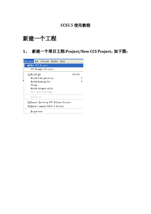
CCS5.5使用教程新建一个工程1、新建一个项目工程:Project/New CCS Project,如下图:2、单击之后,出现如下对话框:设置工程名,路径,设备型号,仿真器型号(可以后需仿真时设置)。
高级设置中的内容直接使用默认设置就可以。
设置完成后单击Finish。
3、完成上步后,建立的工程如下图:不选择仿真器型号时,targetConfigs不会生成新建源文件1、新建源文件File->New->Source File,如下图:2、设置源文件名称和源文件的类型添加已有的源文件1、右击工程选择Add Files2、选择需要添加进工程的文件Properties设置1、进入properties设置2、添加头文件,可点击添加按钮添加头文件路径和具体的头文件,3、添加库文件上面添加具体文件,下面添加搜索路径编译当所有的文件都添加完成后,现在就是对源文件进行编译了。
1、Project-〉Build All,如下图:2、点击build all之后,出现如下对话框:3、编译结束后,会在Console 窗口显示编译结果信息,而在Problems 窗口中显示错误、告警等信息,如下图:配置仿真器当编译完成后,开始进行调试1、File—>New—〉TargetConfigurationFile,如下图:2、选择Target Configuration File之后出现如下对话框:3、设置文件名之后,单击Finish,出现如下对话框:Connection选择仿真器型号;device选择设备型号。
设置完毕后单击save。
4、连接仿真器将仿真器xds100v2 与TMS320F28035 开发板连接好,并通电,然后点击右边的TestConnection按钮。
会出现连接目标板信息,在信息最后当有“The JTAG DR Integrity scan-test has succeeded”指示时,说明连接成功。
CCS5.5的详细操作说明
CCS5.5的详细操作说明CCS5.5详细操作说明1、系统要求CCS5.5要求运行于Windows操作系统(推荐使用Windows 10),并且需要至少4GB的内存和50GB的硬盘空间。
另外,还需要安装Java 8以及其他依赖的软件。
2、安装步骤2.1 安装包从官方网站上CCS5.5的安装包,并保存到本地。
2.2 运行安装程序双击安装包,运行安装程序。
按照向导提示,选择安装路径和相关选项,在安装过程中需要输入序列号进行激活。
2.3 完成安装等待安装程序完成所有的文件复制和配置操作,安装完成后,完成按钮。
3、登录和设置3.1 启动CCS5.5从开始菜单或桌面快捷方式启动CCS5.5:3.2 登录CCS在登录界面输入用户名和密码,登录按钮。
3.3 设置工作环境在登录成功后,进入CCS的主界面。
根据需要,可以进行一些基本的设置,例如界面语言、默认工作区等。
4、创建项目4.1 新建项目在主界面菜单中的“项目”选项,选择“创建新项目”。
根据需要选择项目类型和关联文件,输入项目名称等信息,完成按钮。
4.2 添加源文件在项目资源管理器中选择新建的项目,右键并选择“添加文件”。
选择需要添加的源文件,确定。
4.3 编辑源文件双击打开源文件,在编辑器中进行代码编写和修改。
5、编译和调试5.1 编译项目在主界面中选择项目,菜单中的“编译”选项,选择所需的编译选项。
等待编译完成。
5.2 调试项目在主界面中选择项目,菜单中的“调试”选项,选择所需的调试选项。
使用调试工具进行代码的单步执行、变量查看等。
6、导出和部署6.1 导出可执行文件在主界面中选择项目,菜单中的“导出”选项,选择所需的导出选项。
将的可执行文件保存到指定位置。
6.2 部署到目标设备将导出的可执行文件拷贝到目标设备中,并按照设备的要求进行部署和配置。
附件:本文档中所涉及的附件包括安装包、示例源代码等。
法律名词及注释:- CCS:Code Composer Studio,一款针对嵌入式开发的集成开发环境。
windows2003手工安装配置php5详细指南

标题:[原创]windows2003手工安装配置php5详细指南正文:今天,服务器进行PHP环境的配置,先在百度搜集了一些相关资料进行参考,然后开始手工配置PHP5环境(个人比较喜欢绿色免安装的东西)。
在Windows环境下安装PHP有两种方法:手工配置环境或者使用PHP安装包进行安装。
据PHP官方手册上称安装PHP 最好的选择是手工安装。
在手工安装中安装PHP最好的方式便是将所有PHP有关的文件都放入同一目录,并在系统的P ATH环境变量中设置此目录。
在WINDOWS环境配置PHP5,你必须明白这两个名词的函义:ISAPI(Internet Server Application Program Interface):即Internet 服务器应用程序编程接口。
CGI (Common Gateway Interface):即通用网关接口1、介绍使用安装程序进行安装:PHP 的Windows 安装程序可以在/downloads.php下载。
点击Windows Binaries 下的PHP 5.2.2 installer(选择最新版) 即可下载。
它会为IIS、PWS 和Xitami 安装CGI 版本的PHP,并配置好web 服务器。
该安装程序不包含任何外部的PHP 扩展(PHP_*.dll)。
如果需要,可以在Windows ZIP 包和PECL 中找到。
注: 虽然Windows 安装程序是让PHP 工作的最容易的方法,但是它有很多限制。
例如,它不支持自动安装PHP 扩展。
使用安装程序安装PHP 不是最好的方式。
警告:请注意,这种安装方式安装的PHP 不是安全的。
如果需要一个安全的PHP 设置,最好使用手动方式安装,并手动设置好每个选项。
该自动安装程序能够让用户立即使用PHP,但是这不意味着可以用于在线的服务器中。
2、介绍使用压缩包进行手工安装:PHP 的手工安装程序可以在/downloads.php下载。
CCS5使用教程
CCSv5使用教程1、CCSv5软件的安装打开CCSv5的安装包,运行安装包主目录下面的ccs_setup_5.2.1.00018.exe,一路next直到安装完成。
(注意:安装包应放在英文目录下)2、注册破解首次运行CCSv5需要进行注册,按照软件启动提示或者在help菜单栏下打开注册界面,添加安装包license注册文件,提示注册成功,破解完成。
3、仿真器的安装SEED XDS510PLUS打开仿真器的驱动安装包,在选择安装目录时选择CCSv5安装目录下的ccs 5.2\ccsv5\ccs_base,将驱动安装在此。
4、项目工程的建立(1)TI官网下载DSP2833x的标准库文件,安装标准库文件。
稍后做库文件的整理。
(2)在你常用的盘符下面建立一个DSP Experiment文件夹,在建立一个名为DSPlib的子文件夹,并在DSPLib文件夹下建立名为Cmd,Lib,Source,Prj的四个文件夹。
(3)打开标准库的安装目录,在DSP2833x_common和DSP2833x_headers 文件夹下整理出*.cmd存放在Cmd文件夹下,主要有下图的文件。
整理出*.h,*.c,*.asm文件存放在Lib文件夹下。
如图。
在Source文件夹下建立main.c的文件。
至此建立工程必备的文件都已经准备齐。
(4)(4) 在DSP Experiment文件夹下建立example1文件夹,并拷贝Cmd,Lib,Source,Prj到此文件夹下。
然后打开ccsv5,选择默认的工程项目文件夹为DSP Experiment,并确定。
(5)Project—>New CCS Project,新建工程,并作如下填写。
点击Finish,工程建立完成。
如图。
对默认添加的28335_RAM_lnk.cmd点右键选择如图,隐藏该文件。
拖动example1下的除去Prj文件夹的其他文件夹到ccsv5的工程项目下。
对example点右键打开编译选项。
ccs5.5详细安装过程

一、ccs5.5 安装详解。
1、双击ccs_setup_5.5.0.exe
2、若出现下面页面,点击yes
3、选择第一项,点击next
4、设置安装路径
5、选择custom
6、
7、
8、
9、选择next,开始安装
10、进入安装过程
11、安装完成,开始进行破解
12、双击桌面上的图标,打开ccs5.5软件,进行注册破解
13、将安装文件夹中的安装证书拷贝到刚才的安装路径对应的文件夹中。
14、破解成功,安装结束。
二、仿真器驱动软件安装与配置
1、双击驱动程序。
2、
3、
4、
5、
6、
7、将仿真器连接设备后,将仿真器连接到计算机,打开计算机的设备管理器可以看到含有
叹号的没有识别的设备。
8、
9、
10、识别成功
三、将ccs与DSP实验板连接
1、File -> New -> Target Configuration File
2、
3、。
C Free 5程序调试方法

C Free 5程序调试方法C Free 5是一款常用的C语言集成开辟环境(IDE),它提供了许多方便的功能,其中最重要的之一是程序调试。
在软件开辟过程中,调试是一个不可或者缺的环节,它可以匡助开辟人员找出程序中的错误并进行修复。
本文将介绍C Free 5中的五种常用的程序调试方法,以匡助读者更好地利用这一强大工具。
第一种调试方法是使用断点。
断点是调试过程中的一个标记点,当程序执行到这个点时会暂停运行,开辟人员可以在此时检查变量的值、观察程序的执行流程等。
在C Free 5中,设置断点非常简单。
只需在代码行的左侧单击鼠标左键即可添加断点,再次单击即可取销断点。
通过设置适当的断点,开辟人员可以有针对性地调试程序,提高调试效率。
第二种调试方法是使用单步执行。
单步执行允许开辟人员逐行执行程序,以便查看程序的执行过程。
C Free 5提供了多种单步执行的方式,如单步进入、单步过程、单步返回等。
这些方式可以匡助开辟人员深入理解程序的工作原理,并找出可能存在的问题。
第三种调试方法是使用观察窗口。
观察窗口可以显示变量的值,开辟人员可以在程序运行过程中实时监测变量的变化。
在C Free 5中,观察窗口可以通过菜单栏的“调试”选项打开,并在需要监测的变量上右键单击选择“添加到观察窗口”。
通过观察窗口,开辟人员可以及时发现变量值的异常或者错误,从而更快地找到问题所在。
第四种调试方法是使用条件断点。
条件断点是一种特殊的断点,惟独当满足特定条件时,程序才会在该处暂停执行。
在C Free 5中,可以通过在断点上右键单击并选择“条件”来设置条件断点。
条件断点可以匡助开辟人员在特定情况下定位问题,提高调试的针对性。
第五种调试方法是使用日志输出。
日志输出是一种将程序运行信息输出到文件中的方法,开辟人员可以通过查看日志文件来了解程序的执行情况。
在C Free 5中,可以使用printf函数将需要输出的信息打印到日志文件中。
通过分析日志文件,开辟人员可以找到程序中的潜在问题,并进行相应的调试。
irc5 故障排除操作手册

irc5 故障排除操作手册
1. 检查网络连接:确认网络连接是否正常,确保电脑或服务器上的网络连接没有问题。
2. 检查IRC客户端软件设置:确保IRC客户端的设置正确,
包括服务器地址、端口号、身份验证等。
3. 检查防火墙设置:如果电脑或服务器上有防火墙,确保正确配置以允许IRC流量通过。
4. 检查ISP限制:有些ISP可能限制或阻止IRC连接,请检查是否存在此类限制。
5. 重启设备:有时候重启电脑或服务器可以解决网络连接问题。
6. 使用替代服务器:尝试连接到其他可用的IRC服务器,以
确定是否是特定服务器的问题。
7. 检查IRC服务器的状态:查看IRC服务器的状态页面或联
系相关运维人员,以确定是否有计划维护或其他问题。
8. 更新IRC客户端软件:确保使用的IRC客户端软件是最新
版本,以避免可能存在的已知问题。
9. 检查其他软件或服务冲突:有时其他软件或服务可能会干扰IRC连接,请检查是否有类似的冲突。
10. 查看日志文件:如果IRC客户端提供了日志功能,查看日志文件以获取更多有关连接问题的信息。
11. 寻求技术支持:如果以上操作都无法解决问题,可以寻求相关技术支持,向专业人士解释问题并获得进一步的帮助。
ML5239 Datasheet

If the number of connected battery cells is in the range of 5 to 10, input the I
same potential as the highest V pin (V5 to V10) of the battery connected to
O Battery cell 5 cell balance control output pin.
I Battery cell 5 low voltage input and Battery cell 4 high voltage input pins.
IC.
O Battery cell 9 cell balance control output pin.
Battery cell 9 low voltage input and Battery cell 8 high voltage input pins.
If the number of connected battery cells is in the range of 5 to 7, input the I
SPI communication speed = 500kHz (max) at four-stage configuration Multi-stage connection ICs: 16 (max)
Cell balance FET driving pin
Temperature sensor input: 4 channels
Operational temperature: -40 to 85°C
Package: 64-pin plastic TQFP
Note)
CY8CKIT-005 MiniProg4程序调试套件指南文档说明书

CY8CKIT-005Kit Guide Doc. # 002-19782 Rev. *BCypress Semiconductor198 Champion Court San Jose, CA 95134-1709CopyrightsCopyrights© Cypress Semiconductor Corporation, 2018-2019. This document is the property of Cypress Semiconductor Corporation and its subsidiaries ("Cypress"). This document, including any software or firmware included or referenced in this document ("Software"), is owned by Cypress under the intellectual property laws and treaties of the United States and other countries worldwide. Cypress reserves all rights under such laws and treaties and does not, except as specifically stated in this para-graph, grant any license under its patents, copyrights, trademarks, or other intellectual property rights. If the Software is not accompanied by a license agreement and you do not otherwise have a written agreement with Cypress governing the use of the Software, then Cypress hereby grants you a personal, non-exclusive, nontransferable license (without the right to subli-cense) (1) under its copyright rights in the Software (a) for Software provided in source code form, to modify and reproduce the Software solely for use with Cypress hardware products, only internally within your organization, and (b) to distribute the Software in binary code form externally to end users (either directly or indirectly through resellers and distributors), solely for use on Cypress hardware product units, and (2) under those claims of Cypress's patents that are infringed by the Software (as provided by Cypress, unmodified) to make, use, distribute, and import the Software solely for use with Cypress hardware products. Any other use, reproduction, modification, translation, or compilation of the Software is prohibited.TO THE EXTENT PERMITTED BY APPLICABLE LAW, CYPRESS MAKES NO WARRANTY OF ANY KIND, EXPRESS OR IMPLIED, WITH REGARD TO THIS DOCUMENT OR ANY SOFTWARE OR ACCOMPANYING HARDWARE, INCLUDING, BUT NOT LIMITED TO, THE IMPLIED WARRANTIES OF MERCHANTABILITY AND FITNESS FOR A PARTICULAR PUR-POSE. No computing device can be absolutely secure. Therefore, despite security measures implemented in Cypress hard-ware or software products, Cypress shall have no liability arising out of any security breach, such as unauthorized access to or use of a Cypress product. CYPRESS DOES NOT REPRESENT, WARRANT, OR GUARANTEE THAT CYPRESS PROD-UCTS, OR SYSTEMS CREATED USING CYPRESS PRODUCTS, WILL BE FREE FROM CORRUPTION, ATTACK, VIRUSES, INTERFERENCE, HACKING, DATA LOSS OR THEFT, OR OTHER SECURITY INTRUSION (collectively, "Secu-rity Breach"). Cypress disclaims any liability relating to any Security Breach, and you shall and hereby do release Cypress from any claim, damage, or other liability arising from any Security Breach. In addition, the products described in these mate-rials may contain design defects or errors known as errata which may cause the product to deviate from published specifica-tions. To the extent permitted by applicable law, Cypress reserves the right to make changes to this document without further notice. Cypress does not assume any liability arising out of the application or use of any product or circuit described in this document. Any information provided in this document, including any sample design information or programming code, is pro-vided only for reference purposes. It is the responsibility of the user of this document to properly design, program, and test the functionality and safety of any application made of this information and any resulting product. "High-Risk Device" means any device or system whose failure could cause personal injury, death, or property damage. Examples of High-Risk Devices are weapons, nuclear installations, surgical implants, and other medical devices. "Critical Component" means any component of a High-Risk Device whose failure to perform can be reasonably expected to cause, directly or indirectly, the failure of the High-Risk Device, or to affect its safety or effectiveness. Cypress is not liable, in whole or in part, and you shall and hereby do release Cypress from any claim, damage, or other liability arising from any use of a Cypress product as a Critical Component in a High-Risk Device. You shall indemnify and hold Cypress, its directors, officers, employees, agents, affiliates, distributors, and assigns harmless from and against all claims, costs, damages, and expenses, arising out of any claim, including claims for product liability, personal injury or death, or property damage arising from any use of a Cypress product as a Critical Com-ponent in a High-Risk Device. Cypress products are not intended or authorized for use as a Critical Component in any High-Risk Device except to the limited extent that (i) Cypress's published data sheet for the product explicitly states Cypress has qualified the product for use in a specific High-Risk Device, or (ii) Cypress has given you advance written authorization to use the product as a Critical Component in the specific High-Risk Device and you have signed a separate indemnification agree-ment.Cypress, the Cypress logo, Spansion, the Spansion logo, and combinations thereof, WICED, PSoC, CapSense, EZ-USB, F-RAM, and Traveo are trademarks or registered trademarks of Cypress in the United States and other countries. For a more complete list of Cypress trademarks, visit . Other names and brands may be claimed as property of their respec-tive owners.Safety Information 41.Introduction51.1Kit Contents (5)1.2Programming and Debugging (5)1.3Bridging (5)1.4Documentation Conventions (6)2.Installing MiniProg472.1MiniProg4 (7)2.2MiniProg4 Installation (8)2.3MiniProg4 LEDs (10)2.4MiniProg4 Buttons (11)3.Technical Description123.1Interfaces (13)3.1.1SWD (13)3.1.2I2C (13)3.1.3SPI (13)3.1.4UART with and without Flow Control (13)3.1.5Reference (13)3.2Connectors (14)3.2.15-Pin Connector (14)3.2.210-Pin Connector (14)3.2.36x2 Connector (15)3.3Power (16)A.Appendix17A.1Regulatory Compliance Information (17)Revision History 18Safety InformationThe CY8CKIT-005 MiniProg4 Program and Debug Kit is intended for use as a development platform for hardware or software in a laboratory environment. In a domestic environment, this product may cause radio interference. In such cases, you may be required to take adequate preventive measures. In addition, this board should not be used near any medical equipment or RF devices.Attaching additional wiring to this product or modifying the product operation from the factory default may affect its performance and cause interference with other apparatus in the immediate vicinity. If such interference is detected, suitable mitigating measures should be taken.The CY8CKIT-005 MiniProg4 Program and Debug Kit, as shipped from the factory, has been verified to meet with the requirements of CE as a Class A product.General Safety InstructionsESD ProtectionESD can damage boards and associated components. Cypress recommends that you work on the board at an ESD workstation, if available. Otherwise, use appropriate ESD protection, such as anantistatic wrist strap attached to a ground, when handling parts.The CY8CKIT-005 MiniProg4 Program and Debug Kits are sensitive toelectrostatic discharge (ESD). Electrostatic charges accumulate on thehuman body and on other equipment. Devices that are subjected to high-energy discharges can suffer permanent damage. Proper ESDprecautions are recommended to prevent loss of functionality. Storeunused CY8CKIT-005 MiniProg4 Program and Debug Kits in theprotective shipping package.End-of-Life/Product RecyclingThe end-of life for this kit is five years from the date of manufacture mentioned as barcode on the back of the box. Contact your nearest recycler for discarding the kit.1IntroductionThe MiniProg4 Program and Debug Kit is an all-in-one programmer and debugger for PSoC 4,PSoC5LP, and PSoC 6 MCU devices. MiniProg4 also provides USB-I2C, USB-SPI and USB-UARTbridging functionality. The MiniProg4 provides a special feature enabling users to write their owncustom firmware through the custom application mode.Figure 1-1. MiniProg41.1Kit ContentsThe CY8CKIT-005 PSoC® MiniProg4 Program and Debug Kit includes:■MiniProg4 programmer/debugger■10-pin ribbon cable■USB Type-A to Type-C Cable■Quick Start Guide1.2Programming and DebuggingThe MiniProg4 programmer/debugger provides the flexibility to work with SWD programming anddebugging interfaces. MiniProg4 supports 32-bit Arm® Cortex®-M0/M0+/M3/M4 PSoC devices.The MiniProg4 debugger is supported by the software tools PSoC Creator, ModusToolbox™,Cypress Programmer, and PSoC Programmer.1.3BridgingMiniProg4 supports USB-I2C, USB-UART and USB-SPI as standard bridging protocols for anydevice. The MiniProg4 bridging capabilities are used by PSoC Creator, ModusToolbox, CypressProgrammer, PSoC Programmer, Bridge Control Panel, and other applications. Tuning softwaretools such as the CapSense Tuner provided by Cypress also use these capabilities.Introduction1.4Documentation ConventionsTable 1-1. Document Conventions for User GuidesConvention UsageCourier New Displays file locations, user-entered text, and source code: C:\...cd\icc\Italics Displays file names and reference documentation:Read about the sourcefile.hex file in the PSoC Designer User Guide.[Bracketed, Bold]Displays keyboard commands in procedures: [Enter] or [Ctrl] [C]File > Open Represents menu paths: File > Open > New ProjectBold Displays commands, menu paths, and icon names in procedures: Click the File menu, and then click Open.Times New Roman Displays an equation: 2 + 2 = 4Text in gray boxes Describes cautions or unique functionality of the product.2.Installing MiniProg4This chapter shows how to install MiniProg4 and its associated PC software.2.1MiniProg4Figure 2-1. Top ViewFigure 2-2. Bottom View2.2MiniProg4 InstallationThe MiniProg4 programmer/debugger is supported by PSoC Programmer, ModusToolbox, CypressProgrammer, and PSoC Creator. Other software, such as Bridge Control Panel, use the PSoCProgrammer COM layer to support MiniProg4 functionality.Note: PSoC Programmer is compatible only with the Windows Operating System however, CypressProgrammer is compatible with Windows, macOS, and Linux. To understand the differencesbetween PSoC Programmer and Cypress Programmer, please see the Cypress ProgrammingSolutions page at /products/psoc-programming-solutions.1.Download and install PSoC Programmer or Cypress Programmer. Follow the on-screeninstructions to install the software.Each programming tool supports a subset of Cypress devices. See respective tooldocumentation for which device each supports.unch PSoC Programmer or Cypress Programmer and connect the MiniProg4 to yourcomputer’s USB port using the provided USB cable. When properly connected, and drivers havebeen installed, the Mode LED either turns ON or will be ramping (slowly increasing anddecreasing brightness) depending on the mode.Note that the MiniProg4 drivers are automatically installed.3.In PSoC Programmer, to connect to the port, in the Port Selection pane, click the MiniProg4device. You can also click Connect/Disconnect button as shown in Figure2-3.If the connection is successful, a status indicator in the lower-right corner of the PSoCProgrammer window turns green and shows “Connected”.You can now use MiniProg4 to program the target device by clicking the Program button.Figure 2-3. PSoC Programmer: MiniProg4 Connect/Disconnect and ProgramFor more information on how to use PSoC Programmer, see Help Topics under the Help menuin PSoC Programmer or press [F1].In Cypress Programmer, to connect to the MiniProg4 probe, click Connect/Disconnect button as shown in Figure2-4.If the connection is successful, a status indicator in the lower-right corner of the CypressProgrammer window turns green and shows “Connected”.You can now use MiniProg4 to program the target device by clicking the Program button. Figure 2-4. Cypress Programmer: MiniProg4 Connect/Disconnect and ProgramFor more information on how to use Cypress Programmer, see View Help under the Help menu in Cypress Programmer or press [F1].2.3MiniProg4 LEDsMiniProg4 has three indicator LEDs - Mode (Amber), Status (Green), and Error (Red) as shown in Figure 2-5. Table 2-1 indicates the behavior of these LEDs for various operations.Figure 2-5. MiniProg4 LEDsTable 2-1. LED representation for various operations of MiniProg4Programming ModeProgramming Status Three LEDsMode Indicator (Amber LED)Status Indicator 1 (Green LED)Status Indicator 2 (Red LED)CMSIS-DAP HID ProgrammingRamping (1 Hz)8 Hz OFF SuccessON OFF ErrorOFF ON IdleOFF OFF CMSIS-DAP Bulk ProgrammingON 8 Hz OFF SuccessON OFF ErrorOFF ON IdleOFF OFF BootloaderN/A 1 Hz OFF OFF Custom Application N/A 8 Hz ON ONInstalling MiniProg42.4MiniProg4 ButtonsMiniProg4 has two buttons that enable switching between various operating modes. Figure2-6shows the location of the buttons. In order to understand switching MiniProg4 modes, refer toFigure2-7.On power-up, MiniProg4 is in CMSIS-DAP/BULK Mode by default. If the Mode Select button ispressed, MiniProg4 enters CMSIS-DAP/HID mode. If the Custom App button is pressed, MiniProg4enters custom application mode where a user can run their own custom applications on the MCUcontained in the MiniProg4. See Figure2-7 for details.For details of LED indications of various modes of MiniProg4, refer to Table2-1.Figure 2-6. MiniProg4 ButtonsFigure 2-7. Various MiniProg4 Button Modes3.T echnical DescriptionMiniProg4 is a protocol translation device. With MiniProg4, the PC host software can communicate through a USB port to the target device to be programmed or debugged, as shown in Figure 3-1.Table 3-1 lists the protocols that are supported by each connector. MiniProg4 enables communication with the target devices using I/O voltage levels from 1.5 V to 5 V. Figure 3-1. System Block DiagramTable 3-1. Connectors / Communication Protocol SupportConnector SWD I 2CSPIUART (With and Without Flow Control)5-pin Supported N/A N/A N/A 10-pin Supported N/A N/A N/A 6x2 headerN/ASupportedSupportedSupported3.1Interfaces3.1.1SWDARM-based devices support the Serial Wire Debug (SWD) protocol. The PSoC 4, PSoC 5LP, andPSoC 6 MCU device families implement this standard, which offers programming and debuggingfunctions. MiniProg4 supports programming and debugging of PSoC 4, PSoC 5LP, and PSoC6devices using SWD through the 5-pin or 10-pin connector.Before programming a PSoC 4, PSoC 5LP, or PSoC 6 MCU device, make sure you review theelectrical connection requirements in the respective device datasheet or in the PSoC 4, PSoC 5LP,and PSoC 6 MCU device programming specifications. You can find the datasheets andprogramming specifications here:/PSoC4/PSoC5LP/PSoC63.1.2I2CI2C is a common serial interface standard. It is mainly used for communication betweenmicrocontrollers and other ICs on the same board but can also be used for intersystemcommunications. MiniProg4 uses an I2C multimaster host controller that allows the tool to exchangedata with I2C-enabled devices on the target board. For example, this feature may be used to tuneCapSense® designs.MiniProg4 serves as a USB-I2C bridge (acts as I2C Master) that can be used to communicate with aI2C slave devices through the Bridge Control Panel software. For I2C connections use the 6×2connector. MiniProg4 has internal pull-up resistors and supports I2C speed up to 1 MHz.3.1.3SPIThe Serial Peripheral Interface (SPI) is a synchronous serial communication interface specificationused for short distance communication, primarily in embedded systems. SPI devices communicatein full duplex mode using a master-slave architecture with a single master.MiniProg4 serves as a USB-SPI bridge (acts as SPI Master) that can be used to communicate with aSPI slave devices through the Bridge Control Panel software. For SPI connections use the 6x2connector. MiniProg4 supports SPI speed up to 6 MHz.3.1.4UART with and without Flow ControlUART is another common serial interface standard. MiniProg4 supports UART, which allows the toolto receive data from UART enabled devices on the target board. MiniProg4 provides UARTcommunication both with and without hardware flow control. In order to enable flow control, RTS andCTS pins are provided in the 6x2 I/O header. If flow control is not required, CTS and RTS pins canbe left floating. Terminal emulators such as Tera Term or PuTTY can be used to communicate withthe target PSoC device. MiniProg4 supports UART speed up to 115200 Baud Rate.3.1.5ReferenceFor more information on the PSoC 4, PSoC 5LP, and PSoC 6 MCU's JTAG, SWD, and I2Cinterfaces, see the PSoC 4, PSoC 5LP, and PSoC 6 Technical Reference Manuals.For more details on how to use MiniProg4 with Bridge Control Panel, refer to the Bridge ControlPanel Help document.3.2Connectors3.2.15-Pin ConnectorThe 5-pin connector is configured as a single row with a 100-mil pitch. Suggested mating connectorpart number is Molex Connector Corporation 22-23-2051.Figure 3-2. 5-Pin Connector with Pin AssignmentsNote: If the design requires MiniProg4 to be directly plugged to the target board with a 5-pin header,adequate mechanical clearance shall be provided near the 5-pin header on the target board. Thewidth & height of MiniProg4 (5-pin header area) is 25mm x 13mm. If the design cannot meet therequired mechanical clearance, use a stackable header (such as Proto-PIC 20690).3.2.210-Pin ConnectorThe 10-pin connector is configured as a dual row with 50-mil pitch. It is used with a ribbon cable(provided) to mate to a similar connector on the target board. The signal assignment is shown inFigure3-3. Suggested mating connector part number is CNC Tech 3220-10-0300-00 or Samtec Inc.FTSH-105-01-F-DV-K-TR.Figure 3-3. 10-Pin Connector with Pin AssignmentsHere is a summary of the protocols and related pin assignments. The pin mapping is also shown on the back of the MiniProg4 case.3.2.36x2 ConnectorThis connector supports all the communication protocols like I 2C, SPI, UART (with or without flow control supported by MiniProg4). Figure 3-4 shows the pin assignments. They are also shown on the back of the MiniProg4 case.Figure 3-4. 6x2 Connector Pin AssignmentsTable 3-2. Communication Protocol Pin AssignmentsProtocolSignal 5-Pin 10-Pin SWDSDIO52SCK 44XRES3103.3PowerMiniProg4 can be powered using the USB interface.On kits/boards where there is a single power supply for the entire board, MiniProg4 can supplypower to the board. However, this supply is limited to approximately 200 mA, and is protectedagainst excess current draw. You can select 1.8 V, 2.5 V, 3.3 V, or 5 V from PSoC Programmer orCypress Programmer. The 5 V supply may vary between 4.25 V–5.5 V, because it is supplieddirectly from the USB port. The maximum deviation for other voltages is +5%.Note:Some PSoC device families do not support 5 V operation. Refer to the respective devicedatasheet for supported voltage selection.Voltage stress beyond acceptable limits can permanently damageMiniProg4. Programming signals can withstand over-voltage up tomaximum 12 V and minimum up to –5 V. Communication bridge signals(I2C, UART & SPI) can withstand over-voltage only up to maximum 6 Vand minimum up to –1 V.A.AppendixA.1Regulatory Compliance InformationThe CY8KCIT-005 MiniProg4 Program and Debug Kit complies with the CE-Low Voltage Directive2006/95/EC (Europe) safety requirement. It has been tested and verified to comply with the followingelectromagnetic compatibility (EMC) regulations.■CISPR 22 - Emissions■EN 55022 Class A - Immunity (Europe)■CE - EMC Directive 2004/108/EC■CE Declaration of ConformityDocument Revision HistoryDocument Title: CY8CKIT-005 MiniProg4 Program and Debug Kit Guide Document Number: 002-19782Revision ECN#Issue Date Origin ofChangeDescription of Change**628449410/31/2018NMIT New kit guide.*A637876211/08/2018SRDS Updated Installing MiniProg4chapter on page7:Updated “MiniProg4 Installation” on page8:Updated description.Updated Figure2-3.*B658102405/24/2019SRDS Updated Copyright information.。
JBC P405 脚踏板说明书
INSTRUCTION MANUALPedalP4052PedalRef. P-405Pedal ..............................................................1 unitManual .................................................... 1 unit Ref. 0028917ConnectionsPacking ListThe following items are included:This manual corresponds to the following references:P-405Connect the pedal to JBC station or peripherals. The connector is identified by the designation “PEDAL ”.Pedal Compatibility* not included, sold separatelyP405 is compatible with JBC devices as shown in the table in the highlighted column.P305* and P005* is also shown in the table below.Marked with means pedal P405 cannot be connected directly to JBCs control unit. A modulemust be used (See next pages “Pedal Set Up”).80 mm100 mm 130 mm 130 mmpara manuales - color gris200 mm4acts: as or as a (Pedal Set Up for:- DDU, HDU, NAU, JNAU, JTU, ALU (Control Units) - PHNK, PHSK, PHBK, PHXK (Preheaters)Select portNote that your first connection is denoted as “a”, the second being “b”, etc. (e.g. PD_a, PD_b,...)Set the duration of the activation time when pressing the pedal once*. For continuousfunctioning keep the pedal pressed.*NB: The same can be applied inversely by continually pressing the pedal and releasing to activate.3. Set the pedal function according to your work needs:2. Select the pedal from the list.1. Enter the Peripherals Menu and select the port which you want to join to the pedal.Note: Peripheral moduls - MSE, MVE or MNE - are needed to connect the pedal to DDU y HDU.17:14Port 1 2 3 4MS aPERIPHERAL Peripheral 1 plugged:Electric Suction ModuleSetupPostponeNote: Peripheral moduls - MSE, MVE or MNE - are needed to connect the pedal to DMU.After connecting one of the mentioned moduls to the station a popup window opens. 2. Select the module from the list of peripheral connections. Remember your first connection isdenoted as “a”, the second being “b”, etc. (e.g. MS_a, MS_b,...). Do the same with the pedal (e.g. PD_a,...)3. Select the port of the tool you want to link to the peripheral.Pedal Set Up for DMU (Control Unit)1. To configure the module MSE/MVE/MNE press Setup in the popup window.4. Press Menu or Back to save changes.Once set up, the module settings can be changed by entering the Peripherals Menu .50 mm60 mm80 mm100 mm 130 mm130 mmpara manuales - color gris200 mm6Pedal Set Up for FAE1, FAE2 (Fume Extractors)Select Port* One-touch activates the pedal funtion until pressed twice. Continous activates the pedal function while pressing the pedal.3. Set the pedal function according to your work needs:2. At the Port Menu select Pedal.1. Enter the Main Menu and select Port .One- and Continous*. Pressed and Released .In the peripherals menu for the “Pedal Activation Mode” choose between “pressed” and “released”.para manuales - color gris200 mm45%3Pad CleaningClean the pads with JBC´s desoldering toolDS360.For this operation JBC´s desoldering stationDSS is needed.DS360MicroDesoldering IronDesoldering*Lift the tweezers from the holder, press andhold the pedal to activate the tweezers anddesolder the component.Once the pedal is released the tweezers entersin hibernation mode and cools down.2* “Press Mode” previously selected5 6PlacingDo not press the pedal.Use the tweezers to position the componenton the previously tinned pad.Note:The inactive tweezers prevents the componentfrom heating up prematurely.50 mm60 mm80 mm100 mmNotes 10Notes50 mm60 mm80 mm100 mm130 mm 130 mmpara manuales - color gris200 mmThis product should not be thrown in the garbage.In accordance with the European directive 2012/19/EU, electronic equipment at the end of its life must be collected and returned to an authorized recycling facility.of defective parts and labour.Warranty does not cover product wear or misuse. In order for the warranty to be valid, equipment must be returned, postage paid, to the dealer where it was purchased.P405 Pedal Ref. P-405- Cable length: 1.9 m / 74.80 in - Total Net weight:232 g / 0.51 lb- Total Package Dimension / Weigt: 155 x 85 x 55 mm / 255 g (L x W x H) 6.10 x 3.35 x 2.17 in / 0.56 lb Complies with CE standards ESD safeSpecifications0028917-291122。
源码安装H2OHttp服务端程序到Ubuntu服务器
源码安装H2OHttp服务端程序到Ubuntu服务器⾸先安装全家桶apt install -y build-essential zlib1g-dev libpcre3 libpcre3-dev unzip cmake libncurses5-dev libpam0g-dev bison libboost-dev libssl-dev openssl g++ libxml2-dev libcurl3-openssl-dev libpng-dev libfreetype6-dev libfreetype6-dev这个包有时候会安装失败apt install -y libpng12-dev添加账户:groupadd wwwuseradd -s/sbin/nologin -M -g www www下载安装包:解压:tar zxf v2.2.2.tar.gz配置安装⽬录:cmake . -DCMAKE_INSTALL_PREFIX=/usr/local/h2o -DWITH_BUNDLED_SSL=on编译安装:make -j8make install配置⽂件:vim /home/etc/h2o.cf1 access-log: /tmp/h2o.log2 error-log: /tmp/h2o.err3 pid-file: /tmp/h2o.pid4 max-connections: 5125 file.send-gzip: ON6 tcp-fastopen: 37 user: www8 file.index: [ 'index.php', 'index.html' ]9 file.mime.addtypes:10 text/html: .html .htm .shtml11 text/css: .css12 text/xml: .xml13 image/gif: .gif14 image/jpeg: .jpeg .jpg15 application/javascript: .js16 application/atom+xml: .atom17 application/rss+xml: .rss1819 text/mathml: .mml20 text/plain: .txt21 text/vnd.sun.j2me.app-descriptor: .jad22 text/vnd.wap.wml: .wml23 text/x-component: .htc2425 image/png: .png26 image/tiff: .tif .tiff27 image/vnd.wap.wbmp: .wbmp28 image/x-icon: .ico29 image/x-jng: .jng30 image/x-ms-bmp: .bmp31 image/svg+xml: .svg .svgz32 image/webp: .webp3334 application/font-woff: .woff35 application/java-archive: .jar .war .ear36 application/json: .json37 application/mac-binhex40: .hqx38 application/msword: .doc39 application/pdf: .pdf40 application/postscript: .ps .eps .ai41 application/rtf: .rtf42 application/vnd.apple.mpegurl: .m3u843 application/vnd.ms-excel: .xls44 application/vnd.ms-fontobject: .eot45 application/vnd.ms-powerpoint: .ppt46 application/vnd.wap.wmlc: .wmlc47 application/vnd.google-earth.kml+xml: .kml48 application/vnd.google-earth.kmz: .kmz49 application/x-7z-compressed: .7z50 application/x-cocoa: .cco51 application/x-java-archive-diff: .jardiff52 application/x-java-jnlp-file: .jnlp53 application/x-makeself: .run54 application/x-perl: .pl .pm55 application/x-pilot: .prc .pdb56 application/x-rar-compressed: .rar57 application/x-redhat-package-manager: .rpm58 application/x-sea: .sea59 application/x-shockwave-flash: .swf60 application/x-stuffit: .sit61 application/x-tcl: .tcl .tk62 application/x-x509-ca-cert: .der .pem .crt63 application/x-xpinstall: .xpi64 application/xhtml+xml: .xhtml65 application/xspf+xml: .xspf66 application/zip: .zip6768 application/octet-stream: .bin .exe .dll69 application/octet-stream: .deb70 application/octet-stream: .dmg71 application/octet-stream: .iso .img72 application/octet-stream: .msi .msp .msm7374 application/vnd.openxmlformats-officedocument.wordprocessingml.document: .docx75 application/vnd.openxmlformats-officedocument.spreadsheetml.sheet: .xlsx76 application/vnd.openxmlformats-officedocument.presentationml.presentation: .pptx7778 audio/midi: .mid .midi .kar79 audio/mpeg: .mp380 audio/ogg: .ogg81 audio/x-m4a: .m4a82 audio/x-realaudio: .ra8384 video/3gpp: .3gpp .3gp85 video/mp2t: .ts86 video/mp4: .mp487 video/mpeg: .mpeg .mpg88 video/quicktime: .mov89 video/webm: .webm90 video/x-flv: .flv91 video/x-m4v: .m4v92 video/x-mng: .mng93 video/x-ms-asf: .asx .asf94 video/x-ms-wmv: .wmv95 video/x-msvideo: .avi9697 hosts:98 "域名:端⼝":99 #header.add: "strict-transport-security: max-age=39420000; includesubdomains; preload"100 header.add: "X-Frame-Options: SAMEORIGIN"101 header.add: "X-Content-Type-Options: nosniff"102 header.add: "X-XSS-Protection: 1; mode=block"103 listen:104 port: 端⼝105 #ssl:106 #certificate-file: /home/wwwroot/ssl/.crt107 #key-file: /home/wwwroot/ssl/.key108 #dh-file: /home/wwwroot/ssl/dhparam4096.pem109 #minimum-version: TLSv1.1110 #cipher-preference: server111 #cipher-suite: CHACHA20 EECDH+ECDSA+AESGCM EECDH+aRSA+AESGCM EECDH+ECDSA+SHA384 EECDH+ECDSA+SHA256 EECDH+aRSA+SHA384 EECDH+aRSA+SHA256 EECDH+aRSA+RC4 EECDH EDH+aRSA !aNULL !e 112 paths:113 /:114 file.dir: /home/wwwroot/domain/115 redirect:116 url: /index.php/117 internal: YES118 status: 307119 file.custom-handler:120 extension: .php121 fastcgi.connect:122 port: /tmp/php-fpm.sock123 type: unix配置服务:vim /usr/lib/systemd/system/h2o.service1[Unit]2 Description=h2o optimized HTTP server3 After=network.target remote-fs.target nss-lookup.target45[Service]6 PIDFile=/tmp/h2o.pid7 ExecStart=/usr/local/bin/h2o/bin/h2o -c /home/etc/h2o.cf &8 ExecReload=/usr/bin/kill -HUP $MAINPID9 LimitNOFILE=infinity1011[Install]12 WantedBy=multi-user.targetsystemctl enable h2osystemctl start h2osystemctl status h2o关于服务配置的细节:。
ic200cpue05编程
ic200cpue05编程IC200CPUE05是一款常见的工业控制器,被广泛应用于自动化控制系统中。
它具有高性能、可靠性强的特点,可以实现多种控制和通信功能。
本文将详细介绍IC200CPUE05的编程方法及其在工业控制中的应用。
IC200CPUE05是一款基于PLC(可编程逻辑控制器)的控制器,它采用了Modbus通信协议,具备高速处理能力和丰富的输入输出接口。
该控制器可以通过编程实现对不同设备的自动控制,实现生产线的自动化操作。
编程IC200CPUE05的方法主要有两种:Ladder Diagram(梯形图)和Structured Text(结构化文本)。
梯形图是一种图形化的编程语言,类似于电气原理图,由多个横向排列的梯形图组成,每个梯形图由多个逻辑元件组成,如开关、继电器等。
而结构化文本是一种基于文本的编程语言,类似于常见的编程语言,使用类似于C语言的语法进行编程。
在IC200CPUE05的编程中,首先需要对控制器进行初始化设置,包括通信设置、输入输出设置等。
然后,根据实际需求编写程序逻辑,通过逻辑元件的组合和连接实现对设备的控制。
编写程序过程中,可以使用不同的逻辑元件,如逻辑运算符、定时器、计数器等,来实现不同的控制逻辑。
除了基本的控制逻辑外,IC200CPUE05还支持多种通信协议,如Modbus、Profibus等,可以实现与其他设备的数据交换。
通过这些通信协议,IC200CPUE05可以与其他设备进行数据传输和控制指令的交换,实现多设备间的协同工作。
在实际工业控制中,IC200CPUE05的应用非常广泛。
它可以用于自动化生产线的控制,实现对设备的精确控制和自动化操作。
例如,可以通过IC200CPUE05实现对输送带的控制,实现物料的自动装卸和传送。
另外,IC200CPUE05还可以用于环境监测系统的控制,实现对温度、湿度等参数的实时监测和控制。
IC200CPUE05是一款性能强大的工业控制器,具备高速处理能力和丰富的输入输出接口。
CCS v5的安装及使用教程
目录第二章软件的安装与应用 (1)2.1 CCSv5.1的安装 (1)2.2 利用CCSv5.1导入已有工程 (4)2.3 利用CCSv5.1新建工程 (6)2.4 利用CCSv5.1调试工程 (9)2.5 CCSv5.1资源管理器介绍及应用 (16)第二章软件的安装与应用CCS(Code Composer Studio)是TI公司研发的一款具有环境配置、源文件编辑、程序调试、跟踪和分析等功能的集成开发环境,能够帮助用户在一个软件环境下完成编辑、编译、链接、调试和数据分析等工作。
CCSv5.1为CCS软件的最新版本,功能更强大、性能更稳定、可用性更高,是MSP430软件开发的理想工具。
2.1 CCSv5.1的安装(1)运行下载的安装程序ccs_setup_5.1.1.00031.exe,当运行到如图2.1处时,选择Custom 选项,进入手动选择安装通道。
图2.1 安装过程1(2)单击Next得到如图2.2所示的窗口,为了安装快捷,在此只选择支持MSP430 Low Power MCUs的选项。
单击Next,保持默认配置,继续安装。
图2.2 安装过程2图2.3 软件安装中图2.4 软件安装完成(3)单击Finish,将运行CCS,弹出如图2.5所示窗口,打开“我的电脑”,在某一磁盘下,创建以下文件夹路径:-\MSP-EXP430F5529\Workspace,单击Browse,将工作区间链接到所建文件夹,不勾选"Use this as the default and do not ask again"。
图2.5 Workspace选择窗口(4)单击OK,第一次运行CCS需进行软件许可的选择,如图2.6所示。
在此,选择CODE SIZE LIMITED(MSP430)选项,在该选项下,对于MSP430,CCS免费开放16KB的程序空间;若您有软件许可,可以参考以下链接进行软件许可的认证:/index.php/GSG:CCSv5_Running_for_the_first_time,单击Finish即可进入CCSv5.1 软件开发集成环境,如图2.7所示。
C-Free5.0注册码
C-Free5.0注册码最近在使⽤⼀款相当简洁的IDE编译器,使⽤了⼀段时间觉得还⾏,这⾥就和⼤家分享⼀下如何注册吧,因为⽹上很多注册机都是对C-Free 5.0之前版本的,所以这⾥分享⼀个C-Free 5.0的注册码:⽤户名:tianfang电⼦邮件:注册码:2NnUqd3shO2agta0xNjcusfK1LXO因为之前版本的软件可以使⽤源代码⾃动⽣成,下⾯就贴出代码,只需要把下⾯代码在C-Free中编译出来就能⽣成注册码了:#include "stdlib.h"#include "stdio.h"int main(int argc, char* argv[]){char chKey[128] = {0};int i = 0;unsigned int unXORCode, unRemainder, unQuotient, unTmp, unMachineCode;printf("Please Key in the Machine Code:\n");scanf("%d", &unMachineCode);unXORCode = unMachineCode ^ 0x90909090;unRemainder = unXORCode % 0x25;unQuotient = unXORCode;if (unRemainder < 0x11){unRemainder += 0x11;}while (unQuotient != 0){unTmp = unQuotient % unRemainder;unQuotient /= unRemainder;if (unTmp >= 0xa){unTmp = unTmp + 0x61 + 0xf6;unTmp &= 0x0ff;chKey[i] = unTmp;}else{chKey[i] = unTmp + 0x30;}i++;}printf("Key is: \n");while (i >= 0){printf("%c", chKey[i]);i--;}printf("\n");getch();return 0;}。
Cybozu Garoon 5 非常规更新使用许可 服务说明书
■服务对象产品Garoon 5■非常规更新使用许可的内容“Cybozu Garoon 5非常规更新使用许可”提供以下服务。
1.版本升级服务・重大版本升级・次要版本升级2.追加应用软件服务以下的追加应用服务软件可免费使用。
・工作流程・多功能报告・全文搜索服务器 v2・智能手机页面・连接 API・Cybozu KUNAI・Cybozu Desktop2有关各应用软件的详细内容请向才望子信息技术(上海)有限公司(以下称为“Cybozu 上海”)咨询。
※追加应用软件的使用许可范围以Garoon 5的使用许可为准。
另外、请注意使用“Garoon 5 全文搜索服务器”、“Cybozu Desktop 2”时需要另外安装其他软件。
※「Cybozu Garoon 5 连接API」是客户仅以继续使用Cybozu Garoon 5为目的时可与其他系统整合。
3.技术支持服务・电子邮件支持・电话支持4.来自Cybozu上海的通知服务通过Cybozu上海的主页或电子邮件提供产品的通知以及其他信息。
被版本标记「.」划分的3个数字中,第一个数字表示是主要版本号、第二个数字是次要版本号、最后的数字是修订版本号。
升级主要版本时主要版本号、升级次要版本时次要版本号发生变化,除此以外的维护发布时修订版本号发生变化。
服务内容有随时更改的情况。
最新内容刊载在Cybozu上海的主页上。
请一并参考。
▼Cybozu Garoon 5服务说明书https:///garoon/■服务的提供期间服务的提供期间指在登录“Cybozu Garoon 5”的注册使用许可或非常规更新使用许可的许可密钥时显示的“非常规更新使用许可的结束日”为止的期间。
若在服务提供期间结束后继续使用包含支持的上述服务时,需要更新非常规更新使用许可。
1.常规更新使用许可常规更新使用许可是指延长提供服务期间时需购买的许可。
可购买的时期为提供服务期间内以及服务终止后30天内。
2.非常规更新使用许可非常规更新使用许可是指提供服务期间结束经过31天后,再次接受服务时购买的许可。
- 1、下载文档前请自行甄别文档内容的完整性,平台不提供额外的编辑、内容补充、找答案等附加服务。
- 2、"仅部分预览"的文档,不可在线预览部分如存在完整性等问题,可反馈申请退款(可完整预览的文档不适用该条件!)。
- 3、如文档侵犯您的权益,请联系客服反馈,我们会尽快为您处理(人工客服工作时间:9:00-18:30)。
8
Common Programming Error 5.1
Floating-point values are approximate, so controlling counting loops with floating-point variables can result in imprecise counter values and inaccurate tests for termination.
(1 of 1)
Increment for counter Condition tests for counter’s final value
16 } // end main 1 2 3 4 5 6 7 8 9 10
Control-variable name is counter with initial value 1
2006 Pearson Education, Inc. All rights reserved.
9
Error-Prevention Tip 5.1
Control counting loops with integer values.
2006 Pearson Education, Inc. All rights reserved.
OBJECTIVES
In this chapter you will learn: The essentials of counter-controlled repetition. To use the for and do…while repetition statements to execute statements in a program repeatedly. To understand multiple selection using the switch selection statement. To use the break and continue program control statements to alter the flow of control. To use the logical operators to form complex conditional expressions in control statements. To avoid the consequences of confusing the equality and assignment operators.
— Albert Einstein
Who can control his fate?
— William Shakespeare
The used key is always bright.
— Benjamin Franklin
Intelligence… is the faculty of making artificial objects, especially tools to make tools.
5.11
5.12
(Optional) Software Engineering Case Study: Identifying Objects’ States and Activities in the ATM System
Wrap-Up
Байду номын сангаас
2006 Pearson Education, Inc. All rights reserved.
2006 Pearson Education, Inc. All rights reserved.
1 2 3 4 5 6 7 8 9 10 11 12 13 14 15 16 17 18
// Fig. 5.1: fig05_01.cpp // Counter-controlled repetition. #include <iostream> using std::cout; using std::endl; int main() { int counter = 1; // declare and initialize control variable while ( counter <= 10 ) // loop-continuation condition { cout << counter << " "; counter++; // increment control variable by 1 } // end while
11
Good Programming Practice 5.2
Too many levels of nesting can make a program difficult to understand. As a rule, try to avoid using more than three levels of indentation.
14
Outline
fig05_02.cpp
int main() { // for statement header includes initialization, // loop-continuation condition and increment. for ( int counter = 1; counter <= 10; counter++ ) cout << counter << " "; cout << endl; // output a newline return 0; // indicate successful termination
10
Good Programming Practice 5.1
Put a blank line before and after each control statement to make it stand out in the program.
2006 Pearson Education, Inc. All rights reserved.
2006 Pearson Education, Inc. All rights reserved.
1 2 3 4 5 6 7 8 9 10 11 12 13 14 15
// Fig. 5.2: fig05_02.cpp // Counter-controlled repetition with the for statement. #include <iostream> using std::cout; using std::endl;
Examples Using the for Statement
do…while Repetition Statement switch Multiple-Selection Statement break and continue Statements
Logical Operators Confusing Equality (==) and Assignment (=) Operators Structured Programming Summary
2006 Pearson Education, Inc. All rights reserved.
2006 Pearson Education, Inc. All rights reserved.
15
Common Programming Error 5.2
Using an incorrect relational operator or using an incorrect final value of a loop counter in the condition of a while or for statement can cause off-by-one errors.
7
Outline
Control-variable name is counter with variable initial value 1
fig05_01.cpp
(1 of 1)
Condition tests for counter’s final value
Increment the value in counter
— Henri Bergson
Every advantage in the past is judged in the light of the final issue.
— Demosthenes
2006 Pearson Education, Inc. All rights reserved.
3
2006 Pearson Education, Inc. All rights reserved.
13
5.3 for Repetition Statement
• for repetition statement
– Specifies counter-controlled repetition details in a single line of code
1
5
Control Statements: Part 2
2006 Pearson Education, Inc. All rights reserved.
2
Not everything that can be counted counts, and not every thing that counts can be counted.
2006 Pearson Education, Inc. All rights reserved.
4
5.1
5.2 5.3
Introduction
Essentials of Counter-Controlled Repetition
