H3C L2TP配置
H3C MSR830路由器L2TP VPN(WEB)配置
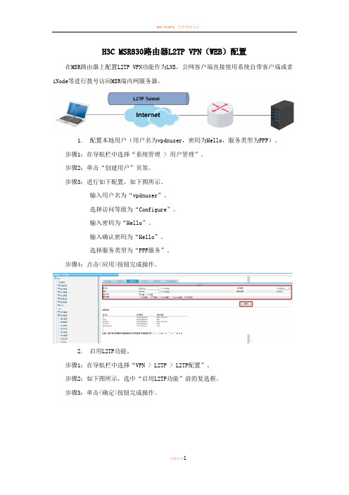
H3C MSR830路由器L2TP VPN(WEB)配置在MSR路由器上配置L2TP VPN功能作为LNS,公网客户端直接使用系统自带客户端或者iNode等进行拨号访问MSR端内网服务器。
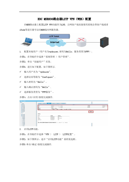
1.配置本地用户(用户名为vpdnuser,密码为Hello,服务类型为PPP)。
步骤1:在导航栏中选择“系统管理 > 用户管理”。
步骤2:单击“创建用户”页签。
步骤3:进行如下配置,如下图所示。
输入用户名为“vpdnuser”。
选择访问等级为“Configure”。
输入密码为“Hello”。
输入确认密码为“Hello”。
选择服务类型为“PPP服务”。
步骤4:点击<应用>按钮完成操作。
2.启用L2TP功能。
步骤1:在导航栏中选择“VPN > L2TP > L2TP配置”。
步骤2:如下图所示,选中“启用L2TP功能”前的复选框。
步骤3:单击<确定>按钮完成操作。
3.修改ISP域system的PPP认证方案。
步骤1:在L2TP配置页面单击<新建>按钮,进入新建L2TP用户组的页面。
步骤2:选择PPP认证方式为“CHAP”。
步骤3:选择ISP域名为“system”(缺省的ISP域)。
步骤4:单击“ISP域”下拉框后的<修改>按钮,进入修改ISP域的页面。
步骤5:如下图所示,选择PPP认证方案的主用方案服务器类型为“Local”。
步骤6:单击<确定>按钮完成ISP域的配置,返回到新建L2TP用户组的页面。
4.配置为用户侧分配地址所用的地址池。
步骤1:在新建L2TP用户组的页面单击“用户地址”下拉框后的<新建>按钮。
步骤2:在新建用户地址的页面进行如下配置,如下图所示。
选择域名为“system”。
输入地址池编号为“1”。
输入开始地址为“192.168.2.100”, 可以是任意地址,但不能与公司内网地址段相同。
输入结束地址为“192.168.2.254”,可以是任意地址,但不能与公司内网地址段相同。
H3C路由器L2TP配置详解

H3C路由器L2TP配置详解H3C路由器L2TP配置详解1:引言L2TP(Layer 2 Tunneling Protocol)是一种用于在公共互联网上建立虚拟私人网络(VPN)连接的协议。
本文将详细介绍如何在H3C路由器上配置L2TP协议。
2:确认硬件和软件要求在开始配置L2TP协议之前,请确保满足以下硬件和软件要求:- H3C路由器设备- 最新的H3C路由器操作系统- 有效的许可证3:步骤一、创建L2TP配置文件要创建L2TP配置文件,请按照以下步骤操作:- 连接到H3C路由器设备。
- 使用管理员权限登录。
- 打开路由器CLI(命令行界面)。
- 进入全局配置模式。
- 创建L2TP配置文件,并配置相关参数,如:隧道名称、IP 地址、预共享密钥等。
4:步骤二、配置L2TP隧道一旦L2TP配置文件创建成功,您需要完成以下步骤来配置L2TP隧道:- 进入隧道配置模式。
- 配置隧道类型和IP地址范围。
- 配置L2TP隧道的其他参数,如:数据压缩、最大会话数等。
5:步骤三、配置L2TP服务继续按照以下步骤配置L2TP服务:- 进入L2TP服务配置模式。
- 配置L2TP服务相关参数,如:监听端口、报文加密方式等。
- 配置L2TP客户端的IP地址池。
6:步骤四、配置用户认证为了确保只有经过身份验证的用户才能访问L2TP隧道,您需要配置用户认证。
请按照以下步骤操作:- 进入L2TP用户池配置模式。
- 配置用户认证相关参数,如:认证方式、用户名密码等。
7:步骤五、保存和应用配置完成以上步骤后,请保存并应用您的配置,使其生效。
示例如下:- 保存当前配置。
- 退出并应用配置。
8:附件本文档涉及以下附件:- 示例配置文件- L2TP隧道配置示意图9:法律名词及注释- L2TP(Layer 2 Tunneling Protocol):一种用于在公共互联网上建立虚拟私人网络(VPN)连接的协议。
- VPN(Virtual Private Network):通过使用公共互联网等非专用传输网络,在不同的网络之间建立安全的连接。
H3C MSR830路由器L2TP VPN(WEB)配置

H3C MSR830路由器L2TP VPN(WEB)配置在MSR路由器上配置L2TP VPN功能作为LNS,公网客户端直接使用系统自带客户端或者iNode等进行拨端内网服务器。
号访问MSR1.配置本地用户(用户名为vpdnuser,密码为Hello,服务类型为PPP)。
步骤1:在导航栏中选择“系统管理> 用户管理”。
步骤2:单击“创建用户”页签。
步骤3:进行如下配置,如下图所示。
输入用户名为“vpdnuser”。
选择访问等级为“Configure”。
输入密码为“Hello”。
输入确认密码为“Hello”。
选择服务类型为“PPP服务”。
步骤4:点击<应用>按钮完成操作。
页脚内容12.启用L2TP功能。
步骤1:在导航栏中选择“VPN > L2TP > L2TP配置”。
步骤2:如下图所示,选中“启用L2TP功能”前的复选框。
步骤3:单击<确定>按钮完成操作。
3.修改ISP域system的PPP认证方案。
步骤1:在L2TP配置页面单击<新建>按钮,进入新建L2TP用户组的页面。
步骤2:选择PPP认证方式为“CHAP”。
步骤3:选择ISP域名为“system”(缺省的ISP域)。
步骤4:单击“ISP域”下拉框后的<修改>按钮,进入修改ISP域的页面。
页脚内容2步骤5:如下图所示,选择PPP认证方案的主用方案服务器类型为“Local”。
步骤6:单击<确定>按钮完成ISP域的配置,返回到新建L2TP用户组的页面。
4.配置为用户侧分配地址所用的地址池。
步骤1:在新建L2TP用户组的页面单击“用户地址”下拉框后的<新建>按钮。
步骤2:在新建用户地址的页面进行如下配置,如下图所示。
选择域名为“system”。
输入地址池编号为“1”。
输入开始地址为“192.168.2.100”, 可以是任意地址,但不能与公司内网地址段相同。
输入结束地址为“192.168.2.254”,可以是任意地址,但不能与公司内网地址段相同。
H3C+L2TP+典型配置举例
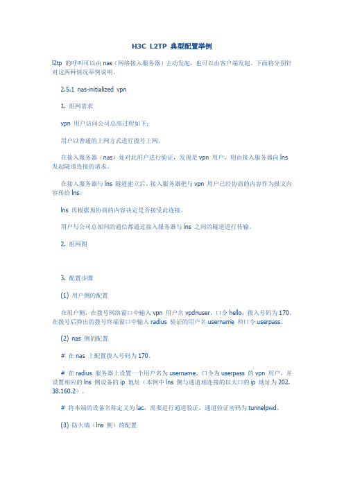
H3C L2TP 典型配置举例l2tp 的呼叫可以由nas(网络接入服务器)主动发起,也可以由客户端发起。
下面将分别针对这两种情况举例说明。
2.5.1 nas-initialized vpn1. 组网需求vpn 用户访问公司总部过程如下:用户以普通的上网方式进行拨号上网。
在接入服务器(nas)处对此用户进行验证,发现是vpn 用户,则由接入服务器向lns 发起隧道连接的请求。
在接入服务器与lns 隧道建立后,接入服务器把与vpn 用户已经协商的内容作为报文内容传给lns。
lns 再根据预协商的内容决定是否接受此连接。
用户与公司总部间的通信都通过接入服务器与lns 之间的隧道进行传输。
2. 组网图3. 配置步骤(1) 用户侧的配置在用户侧,在拨号网络窗口中输入vpn 用户名vpdnuser,口令hello,拨入号码为170。
在拨号后弹出的拨号终端窗口中输入radius 验证的用户名username 和口令userpass。
(2) nas 侧的配置# 在nas 上配置拨入号码为170。
# 在radius 服务器上设置一个用户名为username、口令为userpass 的vpn 用户,并设置相应的lns 侧设备的ip 地址(本例中lns 侧与通道相连接的以太口的ip 地址为202.38.160.2)。
# 将本端的设备名称定义为lac,需要进行通道验证,通道验证密码为tunnelpwd。
(3) 防火墙(lns 侧)的配置# 设置用户名及口令(应与用户侧的设置一致)。
[h3c] local-user vpdnuser[h3c-luser-vpdnuser] password simple hello[h3c-luser-vpdnuser] service-type ppp# 对vpn 用户采用本地验证。
[h3c] domain system[h3c-isp-system] scheme local[h3c-isp-system] ip pool 1 192.168.0.2 192.168.0.100# 启用l2tp 服务,并设置一个l2tp 组。
H3C路由器L2TP穿过NAT接入LNS功能配置
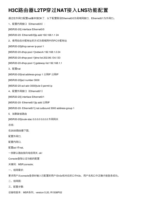
H3C路由器L2TP穿过NAT接⼊LNS功能配置通过在外⽹⼝配置nat基本就OK了,以下配置假设Ethernet0/0为局域⽹接⼝,Ethernet0/1为外⽹⼝。
1、配置内⽹接⼝(Ethernet0/0):[MSR20-20] interface Ethernet0/0[MSR20-20- Ethernet0/0]ip add 192.168.1.1 242、使⽤动态分配地址的⽅式为局域⽹中的PC分配地址[MSR20-20]dhcp server ip-pool 1[MSR20-20-dhcp-pool-1]network 192.168.1.0 24[MSR20-20-dhcp-pool-1]dns-list 202.96.134.133[MSR20-20-dhcp-pool-1] gateway-list 192.168.1.13、配置nat[MSR20-20]nat address-group 1 公⽹IP 公⽹IP[MSR20-20]acl number 3000[MSR20-20-acl-adv-3000]rule 0 permit ip4、配置外⽹接⼝(Ethernet0/1)[MSR20-20] interface Ethernet0/1[MSR20-20- Ethernet0/1]ip add 公⽹IP[MSR20-20- Ethernet0/1] nat outbound 3000 address-group 15.加默缺省路由[MSR20-20]route-stac 0.0.0.0 0.0.0.0 外⽹⽹关总结:在2020路由器下⾯,配置外⽹⼝,配置内⽹⼝,配置acl 作nat,⼀条默认路由指向电信⽹关. ok!Console登陆认证功能的配置关键词:MSR;console;⼀、组⽹需求:要求⽤户从console登录时输⼊已配置的⽤户名h3c和对应的⼝令h3c,⽤户名和⼝令正确才能登录成功。
H3C 防火墙F1000 L2TP配置

H3C 防火墙F1000-A基于Windows自带VPN拨号软件的L2TP配置一组网需求PC作为L2TP的LAC端,F1000-A防火墙作为LNS端。
希望通过L2TP拨号的方式接入到对端防火墙。
用户PC作为LAC,使用windows自带的拨号软件作为客户端软件,拨号接入到对端的Sec Path防火墙。
软件版本如下:Version 5.20, Release 3102三、配置步骤3.1 防火墙上的配置#sysname F1000A#l2tp enable //开启L2TP功能#domain default enable system#vlan 1#domain systemaccess-limit disablestate activeidle-cut disableself-service-url disableip pool 1 1.1.1.1 1.1.1.20 //配置拨号用户使用的地址池#local-user h3cpassword cipher G`M^B<SDBB[Q=^Q`MAF4<1!!service-type telnetlevel 3local-user zhengyamin //配置L2TP拨号用户使用的用户名和地址池password simple 123456level 3service-type ppp#l2tp-group 1 //配置L2TP组undo tunnel authentication //不使用隧道认证allow l2tp virtual-template 1 //使用虚模板1认证#interface Virtual-Template1 //配置L2TP虚模板ppp authentication-mode chap //配置ppp认证方式为chap,使用system默认域 remote address pool 1 //指定使用ip pool 1 给用户分配地址ip address 1.1.1.1 255.255.255.0#interface NULL0#interface GigabitEthernet0/0ip address 10.153.43.20 255.255.255.0#firewall zone trustadd interface GigabitEthernet0/0 //将Ge 0/0和虚接口加入trust区域add interface Virtual-Template1set priority 85#Return3.2 Windows自带拨号软件的设置由于Windows2000系统缺省情况下启动了IPSec功能,因此在发起VPN请求时应禁止IPS ec功能,在命令行模式下执行regedit命令,弹出“注册表编辑器”对话框。
H3C防火墙L2TP配置方法
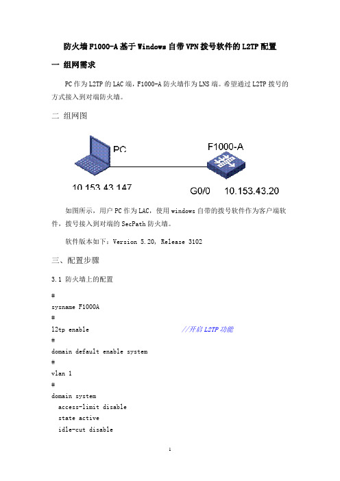
防火墙F1000-A基于Windows自带VPN拨号软件的L2TP配置一组网需求PC作为L2TP的LAC端,F1000-A防火墙作为LNS端。
希望通过L2TP拨号的方式接入到对端防火墙。
二组网图如图所示,用户PC作为LAC,使用windows自带的拨号软件作为客户端软件,拨号接入到对端的SecPath防火墙。
软件版本如下:Version 5.20, Release 3102三、配置步骤3.1 防火墙上的配置#sysname F1000A#l2tp enable //开启L2TP功能#domain default enable system#vlan 1#domain systemaccess-limit disablestate activeidle-cut disableself-service-url disableip pool 1 1.1.1.1 1.1.1.20 //配置拨号用户使用的地址池#local-user h3cpassword cipher G`M^B<SDBB[Q=^Q`MAF4<1!!service-type telnetlevel 3local-user zhengyamin //配置L2TP拨号用户使用的用户名和地址池password simple 123456level 3service-type ppp#l2tp-group 1 //配置L2TP组undo tunnel authentication //不使用隧道认证allow l2tp virtual-template 1 //使用虚模板1认证#interface Virtual-Template1 //配置L2TP虚模板ppp authentication-mode chap //配置ppp认证方式为chap,使用system 默认域remote address pool 1 //指定使用 ip pool 1 给用户分配地址ip address 1.1.1.1 255.255.255.0#interface NULL0#interface GigabitEthernet0/0ip address 10.153.43.20 255.255.255.0#firewall zone trustadd interface GigabitEthernet0/0 //将Ge 0/0和虚接口加入trust区域 add interface Virtual-Template1set priority 85#Return3.2 Windows自带拨号软件的设置由于Windows2000系统缺省情况下启动了IPSec功能,因此在发起VPN请求时应禁止IPSec功能,在命令行模式下执行regedit命令,弹出“注册表编辑器”对话框。
H3C路由器L2TP配置详解

描述
Total session LocalSID RemoteSID LocalTID
会话的数目 本端唯一标识一个会话的数值 对端唯一标识一个会话的数值 隧道的本端标识号
1.1.3 display l2tp tunnel
【命令】 display l2tp tunnel
【视图】 任意视图
【参数】 无
【描述】 display l2tp tunnel 命令用来显示当前 L2TP 隧道的信息。 该命令的输出信息,可以帮助用户确定当前所建立的 L2TP 隧道信息。
【视图】 L2TP 组视图
【参数】 virtual-template-number:指定用于创建新的虚拟访问接口(virtual access interface) 时所用的虚接口模板,取值范围为 0~1023。 remote-name:指定发起连接请求的隧道对端的名称,为 1~30 个字符的字符串, 区分大小写。 domain-name:指定域名,为 1~30 个字符的字符串。
i
命令手册 VPN 分册 L2TP
第 1 章 L2TP 配置命令
第1章 L2TP 配置命令
1.1 L2TP 配置命令
1.1.1 allow l2tp
【命令】 allow l2tp virtual-template virtual-template-number remote remote-name [ domain domain-name ] undo allow
<Sysname> display l2tp session Total session = 1
1-2
命令手册 VPN 分册 L2TP
第 1 章 L2TP 配置命令
LocalSID 1
H3C MSR830路由器L2TP VPN(WEB)配置
H3C MSR830路由器L2TP VPN(WEB)配置在MSR路由器上配置L2TP VPN功能作为LNS,公网客户端直接使用系统自带客户端或者iNode等进行拨号访问MSR端内网服务器。
1.配置本地用户(用户名为vpdnuser,密码为Hello,服务类型为PPP)。
步骤1:在导航栏中选择“系统管理 > 用户管理”.步骤2:单击“创建用户”页签。
步骤3:进行如下配置,如下图所示.✓输入用户名为“vpdnuser".✓选择访问等级为“Configure”.✓输入密码为“Hello”。
✓输入确认密码为“Hello”.✓选择服务类型为“PPP服务”。
步骤4:点击<应用>按钮完成操作.2.启用L2TP功能。
步骤1:在导航栏中选择“VPN 〉 L2TP 〉 L2TP配置”。
步骤2:如下图所示,选中“启用L2TP功能”前的复选框。
步骤3:单击<确定>按钮完成操作.3.修改ISP域system的PPP认证方案。
步骤1:在L2TP配置页面单击<新建>按钮,进入新建L2TP用户组的页面。
步骤2:选择PPP认证方式为“CHAP”。
步骤3:选择ISP域名为“system"(缺省的ISP域)。
步骤4:单击“ISP域"下拉框后的<修改>按钮,进入修改ISP域的页面.步骤5:如下图所示,选择PPP认证方案的主用方案服务器类型为“Local”。
步骤6:单击<确定〉按钮完成ISP域的配置,返回到新建L2TP用户组的页面。
4.配置为用户侧分配地址所用的地址池。
步骤1:在新建L2TP用户组的页面单击“用户地址”下拉框后的<新建〉按钮。
步骤2:在新建用户地址的页面进行如下配置,如下图所示.✓选择域名为“system”.✓输入地址池编号为“1”。
✓输入开始地址为“192.168.2.100",可以是任意地址,但不能与公司内网地址段相同。
H3C路由器简单配置

L2TP是一种工业标准的Internet隧道协议,功能大致和PPTP协议类似,比如同样可以对网络数据流进行加密。
那么H3C路由器L2TP怎么配置呢?下面跟一起来看看吧!目前,各大品牌厂商在无线路由器的配置设计方面增加了密钥、禁止SSID广播等多种手段,以保证无线网络的安全。
设置网络密钥;无线加密协议(WEP)是对无线网络中传输的数据进行加密的一种标准方法。
目前,无线路由器或AP的密钥类型一般有两种,分别为64位和128位的加密类型,它们分别需要输入10个或26个字符串作为加密密码。
许多无线路由器或AP在出厂时,数据传输加密功能是关闭的,必须在配置无线路由器的时候人工打开。
禁用SSID广播;通常情况下,同一生产商推出的无线路由器或AP都使用了相同的SSID,一旦那些企***非法连接的攻击者利用通用的'初始化字符串来连接无线网络,就极易建立起一条非法的连接,给我们的无线网络带来威胁。
因此,建议你最好能够将SSID命名为一些较有个性的名字。
无线路由器一般都会提供“允许SSID广播”功能。
如果你不想让自己的无线网络被别人通过SSID名称到,那么最好“禁止SSID广播”。
你的无线网络仍然可以使用,只是不会出现在其他人所到的可用网络列表中。
通过禁止SSID广播设置后,无线网络的效率会受到一定的影响,但以此换取安全性的提高,笔者认为还是值得的。
禁用DHCP;DHCP功能可在无线局域网内自动为每台电脑分配IP地址,不需要用户设置IP地址、子网掩码以及其他所需要的TCP/IP参数。
如果启用了DHCP功能,那么别人就能很容易使用你的无线网络。
因此,禁用DHCP功能对无线网络而言很有必要。
在无线路由器的“DHCP服务器”设置项下将DHCP服务器设定为“不启用”即可。
启用MAC地址、IP地址过滤在无线路由器的设置项中,启用MAC地址过滤功能时,要注意的是,在“过滤规则”中一定要选择“仅允许已设MAC地址列表中已生效的MAC地址访问无线网络”这类的选项。
H3C(V7)L2TP_client-lns模式
service-type ppp
authorization-attribute user-role network-operator
第三步:创建域abc,对用户采用本地验证。
domain abc
authentication ppp local
第四步:开启L2TP功能
#
l2tp enable
L2tp enable
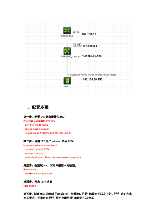
第五步:创建接口Virtual-Template1,配置接口的IP地址为10.0.0.1/24,PPP认证方式为CHAP,并指定为PPP用户分配的IP地址为10.0.0.2。
interface Virtual-Template1
ppp authentication-mode chap domain abc
undo tunnel authentication
tunnel name lns
二
三
version 7.1.059, Alpha 7159
#
sysname H3C
#
ip pool 1 10.0.0.2 10.0.0.100
#
ip unreachables enable
ip ttl-expires enable
一、
第一步:配置LNS路由器接入接口
interface GigabitEthernet0/0
port link-mode route
combo enable copper
ip address 192.168.90.123 255.255.255.0
第二步:创建PPP用户admin,密码1234
local-user admin class network
H3C L2TP-IPSEC办公网典型组网方案
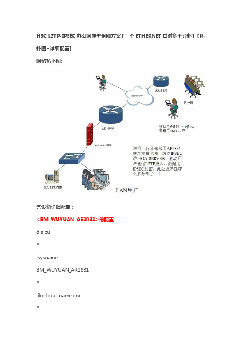
H3C L2TP-IPSEC办公网典型组网方案【一个ETHERNET口对多个分部】【拓扑图+详细配置】网络拓扑图:各设备详细配置:<BM_WUYUAN_AR1831>的配置dis cu#sysnameBM_WUYUAN_AR1831#ike local-name cnc#undo ip optionsource-routing#dialer-rule 1 ip permit #ike peer cncexchange-mode aggressivepre-shared-key cncid-type nameremote-name zxremote-address 60.0.0.1 nat traversal#ipsec proposal cnc#ipsec policy cnc 1 isakmp security acl 3000ike-peer cncproposal cnc#dhcp server ip-pool 1network 10.70.65.0 mask255.255.255.240gateway-list 10.70.65.1dns-list 202.99.224.8 202.99.224.68#interface Bri3/0link-protocol ppp#interface Dialer0link-protocol pppppp pap local-user wy12345kdxwl@service2m.nm password simple xwl9600mtu 1450ip address ppp-negotiatedialer userwy12345kdxwl@service2m.nmdialer-group 1dialer bundle 1nat outbound 3100ipsec policy cnc#interface Ethernet1/0ip address 10.70.65.1255.255.255.240#interface Atm2/0pvc 0/32map bridgeVirtual-Ethernet0#interface Virtual-Ethernet0pppoe-client dial-bundle-number1#interface NULL0#interface LoopBack0#acl number 3000rule 0 permit ip source 10.70.64.0 0.0.0.255 destination 10.70.65.0 0.0.0.15rule 1 permit ip source 10.70.65.0 0.0.0.15 destination 10.70.64.0 0.0.0.255acl number 3100rule 0 deny ip destination 10.70.64.00.0.0.255rule 1 permit ip source 10.70.65.0 0.0.0.15#ip route-static 0.0.0.0 0.0.0.0 Dialer 0 preference 60 #user-interface con 0user-interface vty 0 4user privilege level 3set authentication password cipherN`C55QK<`=/Q=^Q`MAF4<1!!#return<BM_WUYUAN_AR1831><BM_BANGONWAN_EUDEMON200>的配置......................Save the current configuration to the device successfully.<BM_BANGONWAN_EUDEMON200><BM_BANGONWAN_EUDEMON200>dis cu#sysnameBM_BANGONWAN_EUDEMON200#super password level 3 cipherN`C55QK<`=/Q=^Q`MAF4<1!!#nat alg enable ftpnat alg enable dnsnat alg enable icmpnat alg enable netbiosundo nat alg enable h323undo nat alg enable hwccundo nat alg enable ilsundo nat alg enable pptpundo nat alg enable qqundo nat alg enable msnundo nat alg enable user-defineundo nat alg enable sipfirewall mode transparentfirewall system-ip 10.70.64.253 255.255.255.0#firewall statistic system enable #interface Aux0async mode flowlink-protocol ppp#interface Ethernet0/0/0#interface Ethernet0/0/1#interface Ethernet1/0/0#interface Ethernet1/0/1#interface NULL0#interface LoopBack0acl number 3000rule 5 permit ip source 10.70.64.0 0.0.0.255 rule 10 permit ip source 10.70.65.00.0.0.255rule 15 permit ip source 192.168.0.00.0.0.255rule 20 deny ip#firewall zone localset priority 100#firewall zone trustadd interface Ethernet0/0/0add interface Ethernet1/0/0set priority 85#firewall zone untrustadd interface Ethernet0/0/1add interface Ethernet1/0/1set priority 5#firewall zone DMZset priority 50#firewall interzone local trust packet-filter 3000 inboundpacket-filter 3000 outbound #firewall interzone local untrust #firewall interzone local DMZ #firewall interzone trust untrust packet-filter 3000 inboundpacket-filter 3000 outbound #firewall interzone trust DMZ #firewall interzone DMZ untrust #aaaauthentication-scheme default#authorization-scheme default#accounting-schemedefault#domain default##user-interface con 0user-interface aux 0user-interface vty 0 4user privilege level 3set authentication password cipher N`C55QK<`=/Q=^Q`MAF4<1!!#return<BM_BANGONWAN_EUDEMON200><BM_BANGONWAN_P1> 的配置dis cusysnameBM_BANGONWAN_P1 #ike local-name p1#undo ip option source-routing#dialer-rule 1 ip permit #ike peer p1exchange-mode aggressivepre-shared-key cnc id-type nameremote-name zxremote-address 61.138.72.234nat traversal#ipsec proposal p1ipsec policy p1 1 isakmpsecurity acl 3000ike-peer p1proposal p1#dhcp server ip-pool 1network 10.70.65.96 mask255.255.255.240gateway-list 10.70.65.97dns-list 202.99.224.8 202.99.224.68#interface Bri3/0link-protocol ppp#interface Dialer0link-protocol pppppp pap local-user lhkdwtkf1123451@service1m.nm password simple 8810181mtu 1450ip addressppp-negotiatedialer userlhkdwtkf1123451@service1m.nm dialer-group 1dialer bundle 1nat outbound 3100ipsec policy p1#interface Ethernet1/0ip address 10.70.65.97255.255.255.240#interface Atm2/0pvc 0/32map bridgeVirtual-Ethernet0#interface Virtual-Ethernet0pppoe-client dial-bundle-number 1#interface NULL0#acl number 3000rule 0 permit ip source 10.70.64.0 0.0.0.255 destination 10.70.65.96 0.0.0.15rule 1 permit ip source 10.70.65.96 0.0.0.15 destination 10.70.64.0 0.0.0.255acl number 3100rule 0 deny ip destination 10.70.64.00.0.0.255rule 1 permit ip source 10.70.65.96 0.0.0.15#ip route-static 0.0.0.0 0.0.0.0 Dialer 0 preference 60#user-interface con 0user-interface vty 0 4#return<BM_BANGONWAN_P1><BM_BANGONWAN_P2> 的配置dis cu#sysnameBM_BANGONWAN_P2#ike local-name p2#ip option source-routing#dialer-rule 1 ip permit#ike peer dkexchange-modeaggressivepre-shared-key cncid-type nameremote-name zxremote-address 60.0.0.1nat traversal#ipsec proposal dk#ipsec policy dk 1 isakmpsecurity acl 3010ike-peer dkproposal dk#dhcp server ip-pool 1network 10.70.65.112 mask255.255.255.240gateway-list 10.70.65.113dns-list 202.99.224.8 202.99.224.68#interface Bri3/0link-protocol ppp#interface Dialer0link-protocol pppppp pap local-user lhkdtxf123gs@service2m.nm password simple 8270054mtu 1450ip addressppp-negotiatedialer userlhkdtxf123gs@service2m.nmdialer-group 1dialer bundle 1nat outbound 3001ipsec policy dk#interface Ethernet1/0ip address 10.70.65.113255.255.255.240#interface Atm2/0pvc 0/32map bridgeVirtual-Ethernet0#interface Virtual-Ethernet0pppoe-client dial-bundle-number 1#interface NULL0#interface LoopBack0ip address 10.70.65.54255.255.255.255#acl number 3001rule 0 deny ip destination 10.70.64.00.0.0.255rule 1 permit ip source 10.70.65.1120.0.0.15acl number 3010rule 0 permit ip source 10.70.64.0 0.0.0.255 destination 10.70.65.112 0.0.0.15rule 1 permit ip source 10.70.65.112 0.0.0.15 destination 10.70.64.0 0.0.0.255#ip route-static 0.0.0.0 0.0.0.0 Dialer 0 preference 60#user-interface con 0user-interface vty 0 4user privilege level 3set authentication password cipherN`C55QK<`=/Q=^Q`MAF4<1!!#return<BM_BANGONWAN_P2><BM_BANGONGWAN_AR4640>的配置dis cu#sysnameBM_BANGONGWAN_AR4640#super password level 3 cipherI=G>;ZJOROP3HC6>:*%XYA!!#l2tp enable#local-user root password cipherN`C55QK<`=/Q=^Q`MAF4<1!!local-user root service-type telnetlocal-user vpn@ password simple vpnlocal-user vpn@ service-type ppplocal-user test password cipher=W6JJ`N_LBKQ=^Q`MAF4<1!!local-user test service-type ppp#ip pool 1 192.168.0.2 192.168.0.254#aaa enable#ike local-name zx#nat address-group 0 60.0.0.1 60.0.0.6#ike peer cncexchange-modeaggressivepre-shared-key cncid-type nameremote-name cncnat traversalmax-connections 100 #ike peer dkexchange-mode aggressivepre-shared-key cnc id-type nameremote-name dknat traversalmax-connections 100 #ike peer hqexchange-mode aggressivepre-shared-key cnc id-type nameremote-name hqnat traversalmax-connections 100 #ike peer p1exchange-mode aggressivepre-shared-key cnc id-type nameremote-name p1nat traversalmax-connections 100 #ike peer p2exchange-mode aggressivepre-shared-key cnc id-type nameremote-name p2nat traversalmax-connections 100 #ike peer p3exchange-mode aggressivepre-shared-key cnc id-type nameremote-name p3nat traversalmax-connections 100 #ike peer p4exchange-mode aggressivepre-shared-key cnc id-type nameremote-name p4nat traversalmax-connections 100 #ike peer qqexchange-mode aggressivepre-shared-key cnc id-type nameremote-name qqnat traversalmax-connections 100 #exchange-mode aggressivepre-shared-key cncid-type nameremote-name sbnat traversalmax-connections 100 #ike peer zqexchange-mode aggressivepre-shared-key cncid-type nameremote-name zqnat traversalmax-connections 100 #ipsec proposal cnc#ipsec policy zx 1 isakmp security acl 3001proposal cnc#ipsec policy zx 2 isakmp security acl 3001ike-peer qqproposal cnc#ipsec policy zx 3 isakmp security acl 3001ike-peer zqproposal cnc#ipsec policy zx 4 isakmp security acl 3001ike-peer hqproposal cnc#ipsec policy zx 5 isakmp security acl 3001ike-peer dkproposal cncipsec policy zx 6 isakmp security acl 3001ike-peer sbproposal cnc#ipsec policy zx 7 isakmp security acl 3001ike-peer p1proposal cnc#ipsec policy zx 8 isakmp security acl 3001ike-peer p2proposal cnc#ipsec policy zx 9 isakmp security acl 3001ike-peer p3proposal cnc#ipsec policy zx 10 isakmpike-peer p4proposal cnc#dhcp server ip-pool 10network 10.70.64.0 mask 255.255.255.0gateway-list 10.70.64.1dns-list 2.99.224.8 202.99.224.68 #interface Virtual-Template1ppp authentication-modepapip address 192.168.0.1255.255.255.0remote address pool 1#interface Aux0async mode flowlink-protocol ppp#interface Ethernet0/0/0duplex fulldescription connect toS8016_E15/0/6tcp mss 1024ip address 60.0.0.1 255.255.255.248 firewall packet-filter 3500 inbound firewall packet-filter 3500 outbound nat outbound 3000 address-group 0ipsec policy zx#interface Ethernet0/0/1description connect to EUDEMON200e1/0/1ip address 10.70.64.1 255.255.255.0 firewall packet-filter 3500 inbound firewall packet-filter 3500 outbound #interface Ethernet1/0/0#interface Ethernet1/0/1interface NULL0#interfaceLoopback0ip address 10.70.64.99255.255.255.255#acl number 3000rule 0 deny ip destination 10.70.65.00.0.0.255rule 1 permit ip source 10.70.64.0 0.0.0.255acl number 3001rule 0 permit ip source 10.70.65.0 0.0.0.255 destination 10.70.64.0 0.0.0.255rule 1 permit ip source 10.70.64.0 0.0.0.255 destination 10.70.65.0 0.0.0.255acl number 3500rule 0 deny udp source-port eq tftp destination-port eqtftprule 1 deny tcp source-port eq 135 destination-port eq135rule 2 deny udp source-port eq 135 destination-port eq135rule 3 deny udp source-port eq netbios-ns destination-port eq netbios-nsrule 4 deny udp source-port eq netbios-dgm destination-port eq netbios-dgmrule 5 deny udp source-port eq netbios-ssn destination-port eq netbios-ssnrule 6 deny tcp source-port eq 139 destination-port eq139rule 7 deny tcp source-port eq 445 destination-port eq445rule 8 deny tcp source-port eq 593 destination-port eq593rule 9 deny tcp source-port eq 4444 destination-port eq5444rule 11 deny tcp destination-port eq5554rule 12 deny tcp destination-port eq9995rule 13 deny tcp destination-port eq9996rule 14 deny tcp destination-port eq 3127rule 15 deny tcp destination-port eq 1025rule 16 deny tcp destination-port eq 137rule 17 deny tcp destination-port eq 138rule 18 deny tcp destination-port eq 5800rule 19 deny tcp destination-port eq 5900rule 20 deny tcp destination-port eq 8998#l2tp-group 1undo tunnel authenticationallow l2tp virtual-template 1#dhcp server forbidden-ip 10.70.64.240 10.70.64.254#ip route-static 0.0.0.0 0.0.0.0 60.0.0.6 preference 60 #user-interface con 0user-interface aux 0user-interface vty 0 4user privilege level 3set authentication password cipherN`C55QK<`=/Q=^Q`MAF4<1!!#return<BM_BANGONGWAN_AR4640>。
H3C防火墙L2TP配置方法
防火墙F1000-A基于Windows自带VPN拨号软件的L2TP配置一组网需求PC作为L2TP的LAC端,F1000-A防火墙作为LNS端。
希望通过L2TP拨号的方式接入到对端防火墙。
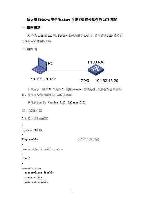
二组网图如图所示,用户PC作为LAC,使用windows自带的拨号软件作为客户端软件,拨号接入到对端的SecPath防火墙。
软件版本如下:Version 5.20, Release 3102三、配置步骤3.1 防火墙上的配置#sysname F1000A#l2tp enable //开启L2TP功能#domain default enable system#vlan 1#domain systemaccess-limit disablestate activeidle-cut disableself-service-url disableip pool 1 1.1.1.1 1.1.1.20 //配置拨号用户使用的地址池#local-user h3cpassword cipher G`M^B<SDBB[Q=^Q`MAF4<1!!service-type telnetlevel 3local-user zhengyamin //配置L2TP拨号用户使用的用户名和地址池password simple 123456level 3service-type ppp#l2tp-group 1 //配置L2TP组undo tunnel authentication //不使用隧道认证allow l2tp virtual-template 1 //使用虚模板1认证#interface Virtual-Template1 //配置L2TP虚模板ppp authentication-mode chap //配置ppp认证方式为chap,使用system默认域remote address pool 1 //指定使用 ip pool 1 给用户分配地址ip address 1.1.1.1 255.255.255.0#interface NULL0#interface GigabitEthernet0/0ip address 10.153.43.20 255.255.255.0#firewall zone trustadd interface GigabitEthernet0/0 //将Ge 0/0和虚接口加入trust区域add interface Virtual-Template1set priority 85#Return3.2 Windows自带拨号软件的设置由于Windows2000系统缺省情况下启动了IPSec功能,因此在发起VPN请求时应禁止IPSec功能,在命令行模式下执行regedit命令,弹出“注册表编辑器”对话框。
H3C路由器的L2TPvpn简单配置
H3C路由器的L2TPvpn简单配置H3C路由器的L2TPvpn简单配置L2TP是一种工业标准的Internet隧道协议,功能大致和PPTP协议类似,比如同样可以对网络数据流进行加密。
那么H3C路由器L2TP 怎么配置呢?下面跟yjbys店铺一起来看看吧!system-view[liuxugang] local-user h3c[liuxugang-luser-h3c] password simple h3c[liuxugang-luser-h3c] service-type ppp[liuxugang-luser-h3c] quit[liuxugang] domain system 进入默认的域system[liuxugang-isp-system] ip pool 1 192.168.1.2 192.168.1.255 给VPN用户设置地址池[liuxugang] quit[liuxugang] l2tp enable 使能l2tp功能[liuxugang] interface Virtual-Template 0 创建虚模版0[liuxugang-Virtual-Template0] ip address 192.168.5.1 255.255.255.0 设定IP地址[liuxugang-Virtual-Template0] ppp authentication-mode pap 使用pap验证方式[liuxugang-Virtual-Template0] remote address pool 1 引用地址池[liuxugang-Virtual-Template0] quit[liuxugang] l2tp-group 1 创建l2tp组[liuxugang-l2tp1] mandatory-lcp 强制LCP自协商[liuxugang-l2tp1] allow l2tp virtual-template 0 在虚接口商启用l2tp[liuxugang-l2tp1] undo tunnel authentication 取消隧道验证。
H3CMSR3620基础上网及L2TP配置
H3CMSR3620基础上⽹及L2TP配置配置思路:启⽤---建⽤户给域---建域给虚模板接⼝--域给虚模板接⼝---虚模板接⼝给L2tp组l2tp enablelocal-user admin class network password simple admin service-type pppdomain abc authentication ppp localinterface Virtual-Template1 ppp authentication-mode chap domain abc remote address 192.168.20.2 ip address 192.168.20.1 255.255.255.0l2tp-group 1 mode lns allow l2tp virtual-template 1 undo tunnel authentication tunnel name LNS⼤写===================================[MSR3620]dis cur#version 7.1.049, Release 0106P21#sysname MSR3620#dhcp enable#password-recovery enable#vlan 1#dhcp server ip-pool pool11network 192.168.11.0 mask 255.255.255.0address range 192.168.11.100 192.168.11.200dns-list 202.99.166.4gateway-list 192.168.11.1#controller Cellular0/0#controller Cellular0/1#interface Aux0#interface Virtual-Template1--------------------(2)创建并进⼊虚模板接⼝1,配本地IP,远端IP(PPP⽤户的IP),PPP认证⽅式为chap并⼯作在名为abc 的域********ppp authentication-mode chap domain abcremote address 192.168.20.2ip address 192.168.20.1 255.255.255.0#interface NULL0#interface GigabitEthernet0/0port link-mode routecombo enable copperip address 172.16.11.200 255.255.255.0nat outbound#interface GigabitEthernet0/1port link-mode route#interface GigabitEthernet0/2port link-mode routeip address 192.168.11.1 255.255.255.0#scheduler logfile size 16#line class auxuser-role network-admin#line class ttyuser-role network-operator#line class vtyuser-role network-operator#line aux 0user-role network-admin#line vty 0 63user-role network-operator#ip route-static 0.0.0.0 0 172.16.11.254#domain abc--------------------------(1)创建并进⼊名为abc的域,为在虚模板接⼝virtual-template 1处认证配置处引⽤************* authentication ppp local-----------对PPP⽤户采取本地认证#domain system#aaa session-limit ftp 32aaa session-limit telnet 32aaa session-limit http 32aaa session-limit ssh 32aaa session-limit https 32domain default enable system#role name level-0description Predefined level-0 role#role name level-1description Predefined level-1 role#role name level-2description Predefined level-2 role#role name level-3description Predefined level-3 role#role name level-4description Predefined level-4 role#role name level-5description Predefined level-5 role#role name level-6description Predefined level-6 role#role name level-7description Predefined level-7 role#role name level-8description Predefined level-8 role#role name level-9description Predefined level-9 role#role name level-10description Predefined level-10 role#role name level-11description Predefined level-11 role#role name level-12description Predefined level-12 role#role name level-13description Predefined level-13 role#role name level-14description Predefined level-14 role#user-group system#local-user admin class network------------(0)创建并进⼊本地⽤户⽤于远端L2TP拨号时的⽤户名和密码password cipher admin//////////////$c$3$vxTKs5M4PsMkgGqspKJ6nkZvHuMM/l2u------配service-type ppp--------------------------------------------------------------配authorization-attribute user-role network-operator----------------------------默认#local-user h3c class networkpassword cipher $c$3$vqedKIgWBgpbwxyyVSgJ6guEj3njpg==service-type pppauthorization-attribute user-role network-operator#l2tp-group 1 mode lns-----------------(3)创建并进⼊编号为1的模式为lns的组************************* allow l2tp virtual-template 1---允许(指定)接收拨号呼叫的虚拟模板接⼝为VT1undo tunnel authentication---取消隧道认证tunnel name LNS---隧道名#l2tp enable---(00)启⽤l2tp协议**********************************#return[MSR3620]dis l2tp tunnelLocalTID RemoteTID State Sessions RemoteAddress RemotePort RemoteName61993 10 Established 1 172.16.11.22 1701 User-2021DHRAIW[MSR3620]dis l2tp sessionLocalSID RemoteSID LocalTID State46887 1 61993 Established[MSR3620]dis versionH3C Comware Software, Version 7.1.049, Release 0106P21Copyright (c) 2004-2014 Hangzhou H3C Tech. Co., Ltd. All rights reserved.H3C MSR36-20 uptime is 0 weeks, 0 days, 3 hours, 11 minutesLast reboot reason : Power onBoot image: cfa0:/msr36-cmw710-boot-r0106p21.binBoot image version: 7.1.049P16, Release 0106P21Compiled Jan 07 2015 18:16:01System image: cfa0:/msr36-cmw710-system-r0106p21.binSystem image version: 7.1.049, Release 0106P21Compiled Jan 07 2015 18:16:01CPU ID: 0x22G bytes DDR3 SDRAM Memory8M bytes Flash MemoryPCB Version: 2.0CPLD Version: 2.0Basic BootWare Version: 1.42Extended BootWare Version: 1.42[SLOT 0]AUX (Hardware)2.0, (Driver)1.0, (CPLD)2.0[SLOT 0]GE0/0 (Hardware)2.0, (Driver)1.0, (CPLD)2.0[SLOT 0]GE0/1 (Hardware)2.0, (Driver)1.0, (CPLD)2.0[SLOT 0]GE0/2 (Hardware)2.0, (Driver)1.0, (CPLD)2.0[SLOT 0]CELLULAR0/0 (Hardware)2.0, (Driver)1.0, (CPLD)2.0[SLOT 0]CELLULAR0/1 (Hardware)2.0, (Driver)1.0, (CPLD)2.0[MSR3620]quit<MSR3620>quit%Jan 7 12:58:41:650 2022 MSR3620 SHELL/5/SHELL_LOGOUT: TTY logg******************************************************************************* Copyright (c) 2004-2014 Hangzhou H3C Tech. Co., Ltd. All rights reserved. * * Without the owner's prior written consent, ** no decompiling or reverse-engineering shall be allowed. *******************************************************************************Line aux0 is available.Press ENTER to get started.。
H3C 路由器L2TP配置
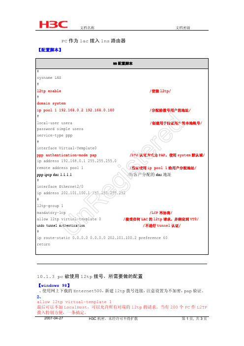
2007-04-27
H3C 机密,未经许可不得扩散
第 1 页, 共 3 页
文档名称
文档密级
3、可以修改 remote name 的 Ethernet500 下载链接: /viewthread.php?tid=402
【windows 2000/xp/nt】 Windows 下 Ethernet 500 安装可能出现若干问题,推荐用 windows 自带拨号程序。 由于 Windows2000 系统缺省情况下启动了 IPSec 功能,因此在发起 VPN 请求时应禁止 IPSec 功能,在命令行模式下执行 regedit 命令,弹出“注册表编辑器”对话框。 在左侧注册表项目中逐级找到:
/创建用于验证用户的本地帐号/
password simple usera
d service-type ppp
#
e interface Virtual-Template0
r ppp authentication-mode pap
/PPP 认证方式为 PAP,使用 system 默认域/
te ip address 192.168.0.1 255.255.255.0
R mandatory-lcp
allow l2tp virtual-template 0
n undo tunnel authentication
/LCP 再协商/ /接受任何 LAC 的 l2tp 请求,并绑定到 VT0/
/不进行 tunnel 认证/
U #
ip route-static 0.0.0.0 0.0.0.0 202.101.100.2 preference 60
HKEY_LOCAL_MACHINE\System\CurrentControlSet\Services\Rasman\Param eters,单击 Parameters 参数,接着在右边窗口空白处单击鼠标右键,选择[新建/双 字节值]并新建一个注册表值(名称为 ProhibitIPSec,值为 1),然后重新启动 Windows2000。 注意设置为 pap 验证,尤其注意要选择 l2tp 拨号,微软默认的是 pptp。
- 1、下载文档前请自行甄别文档内容的完整性,平台不提供额外的编辑、内容补充、找答案等附加服务。
- 2、"仅部分预览"的文档,不可在线预览部分如存在完整性等问题,可反馈申请退款(可完整预览的文档不适用该条件!)。
- 3、如文档侵犯您的权益,请联系客服反馈,我们会尽快为您处理(人工客服工作时间:9:00-18:30)。
目录
目录
第 1 章 L2TP配置 ....................................................................................................................1-1 1.1 L2TP简介 ........................................................................................................................... 1-1 1.1.1 VPDN概述 ............................................................................................................... 1-1 1.1.2 L2TP典型组网应用 .................................................................................................. 1-2 1.1.3 L2TP基本概念 ......................................................................................................... 1-3 1.1.4 L2TP隧道模式及隧道建立过程 ................................................................................ 1-4 1.1.5 L2TP协议的特点...................................................................................................... 1-7 1.1.6 协议规范 .................................................................................................................. 1-7 1.2 L2TP配置任务简介............................................................................................................. 1-8 1.3 配置L2TP基本功能............................................................................................................. 1-8 1.4 配置LAC............................................................................................. 1-9 1.4.1 配置LAC发起L2TP连接请求.................................................................................... 1-9 1.4.2 配置AVP数据的隐藏传输....................................................................................... 1-10 1.4.3 配置LAC侧VPN用户认证....................................................................................... 1-10 1.5 配置LNS端 ....................................................................................................................... 1-11 1.5.1 配置虚接口模板 ..................................................................................................... 1-12 1.5.2 配置本端地址及分配的地址池 ............................................................................... 1-12 1.5.3 配置LNS接收L2TP连接请求.................................................................................. 1-13 1.5.4 配置LNS侧的用户验证 .......................................................................................... 1-13 1.5.5 配置LNS侧VPN用户认证....................................................................................... 1-15 1.5.6 配置L2TP多实例功能 ............................................................................................ 1-15 1.5.7 配置ACCM消息发送 .............................................................................................. 1-15 1.6 配置L2TP连接参数........................................................................................................... 1-16 1.6.1 配置隧道验证......................................................................................................... 1-16 1.6.2 配置隧道Hello报文发送时间间隔........................................................................... 1-17 1.6.3 开启L2TP隧道流控功能......................................................................................... 1-17 1.6.4 强制断开指定的隧道连接....................................................................................... 1-17 1.7 L2TP显示和维护 .............................................................................................................. 1-18 1.8 L2TP典型配置举例........................................................................................................... 1-18 1.8.1 NAS-Initiated VPN................................................................................................. 1-18 1.8.2 Client-Initiated VPN............................................................................................... 1-21 1.8.3 L2TP多域组网应用 ................................................................................................ 1-22 1.8.4 复杂的组网情况 ..................................................................................................... 1-26 1.9 常见配置错误举例 ............................................................................................................ 1-26 1.9.1 错误之一 ................................................................................................................ 1-26 1.9.2 错误之二 ................................................................................................................ 1-27
