TSOP2238中文资料
RS-232多串口扩展器件SP2538及其应用
RS-232多串口扩展器件SP2538及其应用摘要:SP2538是采用低功耗CMOS工艺生产的专用串行口(RS232)扩展芯片,它可将单片机或DSP等原有的单UART串口扩展至5个全双工UART口,从而解决了此类器件串口太少的问题。
文中介绍了SP2538的性能特点,引脚功能及应用方法,并以单片机为例给出了多串口扩展的硬件电路及相应的通信程序。
关键词:RS-232;串口扩展;单片机;SP25381概述SP2538是专用低功耗串行口扩展芯片,该芯片主要是为解决当前基于UART串口通信的外围智能模块及器件较多,而单片机或DSP原有的UART串口又过少的问题而推出的。
利用该器件可将现有单片机或DSP的单串口扩展至5个全双工串口。
与其它具有多串口的单片机或串口扩展方案相比,采用SP2538实现的多串口扩展方案,具有扩展串口数量多、对扩展单片机的软硬件资源占用少、使用方法简单、待扩展串口可实现较高的波特率、成本低廉、性价比高等优点。
同时,它还具有如下特点:●可将单UART串口扩展为5个UART串口;●工作速率范围宽,5个子串口可产生2400bps~9600bps之间的任意波特率;●可全双工工作,母串口和所有子串口都支持全双工UART传输模式;●工作电源电压范围宽:3.3V~5.5V;●典型工作电流为4.6mA(子串口速率为9600bps、VCC为3.3V时);●资源占用少,除占用上位机原有串行口中断外,不占用任何中断资源;●具有节电模式,进入节电模式后,其典型静态电流约8μA;●上位机发送数据可自动唤醒;●输出误差小,所有子串口的输出波特率误差均小于0.08%;●误码率低于10-9(所有串行口数据输入波特率误差小于等于±2%);●接收范围宽,波特率误差小于2.5%时,子串口即可完全正确接收;母串口的接收范围更宽,并可自适应56000bps和57600bps两种标准波特率(fosc—in为20.0MHz时);●可用上位机进行监控,并具有上电复位和看门狗监控输出,适用于没有看门狗或需要更多重监控的高可靠上位机程序监控系统。
成都视普SP2338 数据应用手册
成都视普科技有限公司() AP0223 2003.07
匹配 如需连接 PC 机等必须增加电平转换芯片 如 MAX202 MAX232 等
z 上位机通过改变 ADRI1 ADRI0 地址线状态的方式选择 3 个子串口中的任意一
个 3 个子串口的地址分别为 00
数据的编程说明
A 如上位机只需要向一个子串口发送数据 可先向该串口发送一个字节数
据 再执行 4 条 NOP 指令 向 11 地址写 0X00
其后再向该子串口发
送下一个字节数据 再执行 4 条 NOP 指令… … 以此方式循环发送即可
B 如果上位机需要向两个串口分别发送两个数据块 则可以先分别向两个相
20.0 MHz 15~22pF x 2
图3
第 页 共 11页
成都视普科技有限公司() AP0223 2003.07
9 操作时序
RX0 RX1 RX2 RX3
Wake up data D0 D1 D2 D3 D4 D5 D6 D7
Twake_up
芯片自动唤醒 图4
TX3 ADRO0~1
D0 D1 D2 D3 D4 D5 D6 D7
D0 D1 D2 D3 D4 D5 D6 D7
DATA n
DATA n+1
Taddr_hold
Taddr_hold
Address n
Address n+1
母串口 TX3 发送数据 图6
表 3 操作时限 内容
说明
最小值
Taddr_in
串口 0 数据接收输入口 串口 0 数据发送输出口 串口 1 数据接收输入口 串口 1 数据发送输出口 串口 2 数据接收输入口 串口 2 数据发送输出口 串口 3 数据接收输入口 串口 3 数据发送输出口
82107中文资料

IR Receiver Modules for Remote Control SystemsDescriptionThe TSOP22..YA1 - series are miniaturized receivers for infrared remote control systems. PI N diode and preamplifier are assembled on lead frame, the epoxy package is designed as IR filter.The demodulated output signal can directly be decoded by a microprocessor. TSOP22..YA1 is the standard IR remote control receiver series, support-ing all major transmission codes.Features•Photo detector and preamplifier in one package Parts TableElectrical and Optical CharacteristicsT = 25°C, unless otherwise specifiedSupply Current (Pin 2)I S 5mA Output Voltage (Pin 1)V O - 0.3 to + 6.0V Output Current (Pin 1)I O 5mA Junction T emperature T j 100°C Storage T emperature Range T stg - 25 to + 85°C Operating T emperature Range T amb - 25 to + 85°C Power Consumption (T amb ≤ 85°C)P tot 50mW Soldering T emperaturet ≤ 5 s T sd260°CParameterTest conditionSymbol Value UnitDocument Number • Signals from fluorescent lamps with electronic bal-last with high or low modulation ( see Figure 13 or Fig-ure 14 ).Figure 13. IR Signal from Fluorescent Lamp with low ModulationFigure 14. IR Signal from Fluorescent Lamp with high ModulationDocument Number Package Dimensions in mmDocument Number Ozone Depleting Substances Policy StatementIt is the policy of Vishay Semiconductor GmbH to1.Meet all present and future national and international statutory requirements.2.Regularly and continuously improve the performance of our products, processes, distribution andoperatingsystems with respect to their impact on the health and safety of our employees and the public, as well as their impact on the environment.It is particular concern to control or eliminate releases of those substances into the atmosphere which are known as ozone depleting substances (ODSs).The Montreal Protocol (1987) and its London Amendments (1990) intend to severely restrict the use of ODSs and forbid their use within the next ten years. Various national and international initiatives are pressing for an earlier ban on these substances.Vishay Semiconductor GmbH has been able to use its policy of continuous improvements to eliminate the use of ODSs listed in the following documents.1.Annex A, B and list of transitional substances of the Montreal Protocol and the London Amendmentsrespectively2.Class I and II ozone depleting substances in the Clean Air Act Amendments of 1990 by the EnvironmentalProtection Agency (EPA) in the USA3.Council Decision 88/540/EEC and 91/690/EEC Annex A, B and C (transitional substances) respectively. Vishay Semiconductor GmbH can certify that our semiconductors are not manufactured with ozone depleting substances and do not contain such substances.We reserve the right to make changes to improve technical design and may do so without furthernotice.Parameters can vary in different applications. All operating parameters must be validated for each customer application by the customer. Should the buyer use Vishay Semiconductors products for any unintended or unauthorized application, the buyer shall indemnify Vishay Semiconductors against all claims, costs, damages, and expenses, arising out of, directly or indirectly, any claim of personal damage, injury or death associated with such unintended or unauthorized use.Vishay Semiconductor GmbH, P.O.B. 3535, D-74025 Heilbronn, GermanyTelephone: 49 (0)7131 67 2831, Fax number: 49 (0)7131 67 2423Document Number 。
AXP223中文
版本历史
版本 1.0 1.1
日期 2013.08.30 2013.11.28
描述 第一版 修改部分参数,补充寄存器说明
版权声明
版权所有,违法必究。
非经本公司书面同意,任何单位或个人不得擅自摘抄、复制本文档内容的部分或全部,并不得以任何形式进行传播。任何单位或个人不得 删除、修改或移除本文档版权及所有的权利声明。
功能框图 ............................................................................................................................................................................................................ 12
9.5.
E-Gauge ™ 电量计系统 ............................................................................................................................................................. 27
10.2. 寄存器描述 ......................................................................................................................................................................................32
舒瑞普(传特)技术文档
舒瑞普/传特板式换热器国际公司是全球知名的拼装式(PHE)及钎焊式(CB E)板式换热器专业生产商,为石油化工、机械工业、汽车工业、食品工业、电力、冶金、造船业、暖通、空调制冷行业提供产品和服务。
舒瑞普/传特的产品高度从286mm—4392mm,宽度从114mm—1540mm,接口直径从DN25—DN500,板片厚度从0.4mm—1.0mm,众多系列,数十种型号;最大流量可达4250m³/h;最大换热面积可达1840㎡;最高功罪压力可达2.5MPa;最工作温度可达180℃。
舒瑞普公司目前生产近70种不同规格的板式换热器,为您提供GC、GD、GF、GX、GL、GW系列产品,是迄今为止品种规格最全的板式换热器制造商。
舒瑞普/传特板式换热器有不锈钢SUS304,SUS316L、Ti、Hadtelloy Alloy、Nickel等多种板片材质,适用于各种工况。
在垫片方面提供了NBR、HNBR、EPDM、Viton、NEOPRENE、Silicon Ru bbe等材质。
适用于不同工况需求,确保您得到最适合您工况应用的那一台换热器。
四.板式换热器产品系列﹡同一板片上2种不同的波纹角度﹡垫片槽底部在板片波纹高度的中心平面上﹡两种板片可以组合成6种流道排列﹡高效率的对角流布置﹡接口从DN50-DN500。
﹡综合了GX型板片密封垫片槽的巧妙设计,板片波纹相对中线对称分布,垫片槽深度为波纹深度的一半,垫片槽底部位于波纹板片的中心平面上,科学的设计保证了密封的可靠性。
﹡高性能的对角流设计。
﹡可应用于各个行业。
﹡板片的波纹节距是普通板片波纹节距地2-5倍,允许不规则的固体颗粒自由通过而避免堵塞,波纹节距范围为8~16mm。
﹡宽流道板式换热器专门适用于含有纤维或粘附性颗粒的易堵塞介质。
﹡应用于造纸、食品粗加工、化纤、纺织、制糖、乳胶等等行业。
板式换热器设计选型须知:(1)板式换热器固有特性,如板片材料、密封胶垫等。
BP2338
Bright Power Semiconductor Co. Confidential – Customer Use Only
1
BP2338
非隔离降压型有源 PFC LED 驱动芯片 定购信息
定购型号 BP2338 封装 SOP-8 温度范围 -40 ℃ 到 105 ℃ 2,500 颗/盘 包装形式 编带 打印 BP2338 XXXXXY WWXYY
特点
高压 JFET 快速启动与供电 超快 LED 启动时间(<100mS @85Vac) 内置 600V 功率 MOSFET 有源功率因数校正,高 PF 值,低 THD 高达 95%的系统效率 ± 3% LED 输出电流精度 优异的线电压调整率和负载调整率 电感电流临界连续模式 超低 (300uA) 工作电流 LED 短路/开路保护 电流采样电阻开路保护 逐周期电流限流 芯片供电欠压保护 自动重启功能 过热调节功能
RFBL 1.6V RFBL RFBH VOVP
其中, RFBL 是反馈网络的下分压电阻 RFBH 是反馈网络的上分压电阻 VOVP 是输出电压过压保护设定点 推荐 FB 下分压电阻设置在 5.1KΩ 或更小的值。 为了加强 FB 节点抗噪声能力,可以在 FB 下分压 电阻上并联一个约 100pF 左右的电容。 4 过温调节功能 BP2338 具有过热调节功能,在驱动电源过热时逐 渐减小输出电流,从而控制输出功率和温升,使 电源温度保持在设定值,以提高系统的可靠性。 芯片内部设定过热调节温度点为 140℃。 5 保护功能 BP2338 内置多重保护功能,保证了系统可靠性。 当 LED 开路时,输出电压逐渐上升,FB 引脚可以 在功率管关断时检测到输出电压。 当 FB 升高到 OVP 保护阈值时,会触发保护逻辑并停止开关工作。 系统进入保护状态后,内部高压电路停止对 VCC 充 电, VCC 电压开始下降, 当 VCC 到达欠压保护阈值时, 系统将重启。同时系统不断的检测系统状态,如 果故障解除,系统会重新开始正常工作。 当 LED 短路时,系统工作在 7kHz 低频,以减小短 路功耗。 当变压器饱和时,CS 峰值电压将会比较高。当 CS 电压上升到内部限制值(1.5V)时,该开关周期 马上停止。此逐周期限流功能可以保护功率 MOS 管、功率电感和输出续流二极管。 6 PCB 设计 在设计 BP2338 PCB 板时,需要注意以下事项: 旁路电容
SIM HT46R00X
数据存储器 ...................................................................................................................13 结构 ...................................................................................................................................... 13 特殊数据存储器 .................................................................................................................. 13
TTP233D-KB8_新版原厂规格书
单位 ℃ ℃ V V KV
z DC / AC 特性:(测试条件为室温 = 25 ℃)
参数 工作电压 内部稳压电路输出
工作电流
输入埠 输入埠 输出埠灌电流 Sink Current 输出埠源电流 Source Current 输入脚位上拉电阻 输入脚位下拉电阻
输出响应时间
符号
测试条件
最小值
VDD
2.4
P.S.:
1. 在 PCB 上﹐从触摸板到 IC 接脚的线长越短越好。且此接线与其它线不得平行或交叉。
2. 电源供应必须稳定﹐若供应电源之电压发生飘移或快速漂移或移位﹐可能造成灵敏度异常或误侦测。
3. 覆盖在 PCB 上的板材﹐不得含有金属或导电组件的成份﹐表面涂料亦同。
4. 必须在 VDD 和 VSS 间使用 C1 电容﹔且应采取与装置 IC 的 VDD 和 VSS 接脚最短距离的布线。
2019/08/15
Page 7 of 9
Version:1.0
封装外观尺寸
封装类型 DFN8L
TTP233D-KB8
2019/08/15
Page 8 of 9
Version:1.0
封装配置
TTP233D-KB8 封装类型 DFN8L
8 VDD 7 AHLB 6 TOG 5 LPMB
TTP233D-KB8
z 上电后约有 0.5 秒的稳定时间﹐此期间内不要触摸检测点﹐此时所有功能都被禁止
z 自动校准功能 刚上电的 8 秒内约每 1 秒刷新一次参考值﹐若在上电后的 8 秒内有触摸按键或 8 秒后仍未触摸 按键,则重新校准周期切换为 4 秒
应用范围
z 各种消费性产品 z 取代按钮按键
2019/08/15
施耐德PLC M238

7 一显示单元显示I/O状态 (I0...I13 和 Q0...Q9)。
6
8 一组可插拔螺钉端子(10端口)用于连接6路预执行机构 (24 V c 输出)。
7
9 一组可插拔螺钉端子(6端口)用于连接4路预执行机构 (24 V c 高速输出)。
10 一组可插拔螺钉端子(5端口标志CANopen)用于CANopen总线连接,仅应用于
描述
1
2
3
4
10
9
8
Modicon M238可编程控制器由 TM238 LDD24DT 和 TM238 LFDC24DT 本体单元组成:
5
1 一 mini USB 编程口。 2 一个密封盖
3 一组可插拔端子 (12 端口) 用于连接外部传感器 (24 V c 高速输入)。
4 一组可插拔螺钉端子(7端口),用于连接外部传感器 (24 V c输入)。
___________________________________________________________________________ (1) 每个PLC本体最大允许连接7块扩展模块I/O数量分别为136/192/248I/O (取决于使用的扩展模块
接线方式是 螺钉端子型, 弹簧端子还是HE 10连接器)
TM238 LFDC24DT。
UART多串口扩展器SP2338DP及其应用
UART 多串口扩展器 SP2338DP 及其应用 摘要 2338 是一种新颖的串口扩展器,可将一个高波特率的扩展为 3 个,解决了普通单片机串口太少的问题。
文中给出该器件的主要特性、引脚说明及应用说明,并以 8952 单片 机为例给出多串口扩展应用电路及相应软件。
关键词串口扩展单片机 1 概述 当前,以单片机为核心构成的智能化测控系统及电子产品不断涌现, 为了满足数字化及智能化要求,许多外围电路功能模块、部件、器件及传 感器也具备了串口通信功能。
而现阶段的 8 位、16 位、32 位单片机却大部分仅提供一个串口,这 样就很难满足系统中一方面要与具有功能的串口部件通信,另一方面又要 与上位机通信的要求。
利用 2338 多串口扩展器,可很好地解决此问题。
2 工作特性 2338 是采用低功耗工艺设计的多串口扩展芯片。
该器件可将一个高波特率的串口扩展为 3 个较高波特率的串口,从而 为系统需要多个串口时提供了很好的解决方案。
该器件的主要特性如下*可将 1 个串口扩展为 3 个串口。
*全双工异步工作 4 个串口都为全双工异步工作模式。
*高工作速度 1200——9600 可由晶振频率设定任意非标准波特率。
*波特率设置简单不需软件设置,只需更改输入时钟频率即可。
*波特率误差小每个串口的数据输出波特率误差小于 025 *接收波特率范围宽要求每个串口数据波特率小于 25 即可。
*数据传输误码率极低小于 10-9 接收的数据波特率误差小于 2 时。
*具有节电模式进入节电模式后典型静态电流为 05μ *可自动唤醒任意串口的接收端有数据出现时自动唤醒。
*宽工作电源电压 24——55 *低工作电流典型工作电流为 44 3 封装及引脚说明 该器件具有、和多种封装形式。
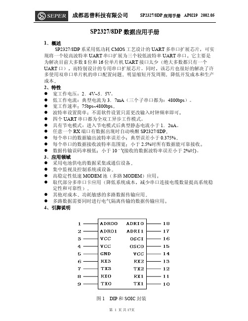
下面以封装形式为例,给出元件的封装及引脚排列,如图 1 所示。
引脚功能及说明见表 1 表 12338 引脚功能 名称编号类型 描述 018 串口 3 接收数据地址线 0117 串口 3 接收数据地址线 101 串口 3 发送数据地址线 012 串口 3 发送数据地址线 108 串口 0 数据接收 09 串口 0 数据发送 111 串口 1 数据接收 110 串口 1 数据发送 213 串口 2 数据接收 212 串口 2 数据发送 36 串口 3 数据接收 37 串口 3 数据发送 16 时钟输入 15 时钟输出 3,4,14-正电源 5-地 4 应用说明 2338 在使用时应遵循以下原则 ①2338 适用于串行数据为 8 位 的应用领域如数据位 7 为位,可选用 2337 器件; ②串口 0——2 为较高波特率的串口子串口。
成都思普 SP2327 8DP 数据应用手册
0XB5 将实现芯片软件复位 复位时间为 21.75mS 如果写入的数据为
0X55 或 0XD5 则芯片将进入 Sleep 模式
z 芯片 Wake up 条件为 向串口 0~串口 3 中的任意一个串口发送数据 由
于 SP2327/8XX 的唤醒时间需要 25mS 左右 用于芯片唤醒的数据将不能够被接
收 建议芯片唤醒处理流程 先发送一个用于唤醒芯片的数据 建议发送
0X63
延时至少 25mS 后即可进行有效的数据传输
注 由于串口 3 的波特率是串口 0 串口 1 串口 2 的波特率的 4 倍 同时
由于没有数据发送完标志 为了快速可靠的传输大量的数据可以采用下面的方法
完全有效的解决波特率不匹配的问题
管脚 类型
I I O O I O I O I O I O I O -----
管脚描述
串口 3 发送数据地址线 0 串口 3 发送数据地址线 1 串口 3 接收数据地址线 0 串口 3 接收数据地址线 1
串口 0 数据接收 串口 0 数据发送 串口 1 数据接收 串口 1 数据发送 串口 2 数据接收 串口 2 数据发送 串口 3 数据接收 串口 3 数据发送
时钟输入 时钟输出
电源 参考地
第 页 共 17页
成都思普科技有限公司
SP2327/8DP 应用手册 AP0219 2002.05
5 设计选型
SP232 X XX
表2 代码 A B
C
A BC
内容 一个 UART 串口扩展为三个 UART 串口芯片系列 7 发送 接收的数据位为 7 位数据 8 发送 接收的数据位为 8 位数据 DP 双列直插封装 SO 双列宽体贴片封装 SS 双列缩小窄体贴片封装
型号T3238
型号:T3238敬告:在操作本机之前请阅读下述内容在提示不能使用手机的场合,如医院、飞机机舱内、加油站、怕无线干扰的地方,请您关闭本设备!插入SIM卡时请确保外接电源已经断开,且SIM 卡放置到位。
首次充电请充满8小时。
在充电的过程中,请不要从手机上取下电池,以防损伤设备。
本机型不具有防水功能,请您注意防水,保持手机的干燥。
如果自行打开或者损伤外壳将不再享受保修服务。
请使用由多普达公司指定的附件和认可的第三方软件,否则如果设备出现问题多普达公司将不承担任何责任。
请使用屏幕保护贴,注意保护好手机屏幕,防止磨损或挤伤。
此类损伤均被认为是人为损坏。
请及时备份数据!多普达公司不承担因产品故障导致信息丢失而造成的一切直接或间接损失。
尤其在更换电池前更加需要备份数据。
本设备中包含有锂电池。
如果电池处理不当,将会有着火和燃烧的危险。
不要分解、挤压、刺穿电池,不要短路电池外部的接头,更不要将其投入火中或者水中。
不要试图打开或者维修该电池,只能使用产品指定的电池来进行更换。
请正确处理电池不要随意丢弃。
由于软件版本更新而造成界面和功能变更,恕不另行通知。
本手册部分截图可能与实际设备显示有差异,请以实际设备显示为准。
有关图片仅作为示意和说明使用,您所购买的具体产品的颜色和外观,请以实物为准。
敬告:在操作本机之前请阅读下述内容当手机使用过长时间后,例如长时间讲电话,电池充电,或是浏览网页,此时手机可能开始变得比较热。
多数情况下,这是正常现象,并不是手机本身有故障,请勿担心。
产品名称环保使用期限主机电源适配器或车用充电器充电座USB数据线耳机软件CD、印刷品、包装材料、泡棉电池注:表格中的某些配件可能不为您的手机标配,请以实际包装盒内的配件为准环保使用期限的起始日期以产品的生产日期为准,部分无法从产品本身直接查询生产日期的配件则以手机整机的生产日期为准。
产品在正常使用的情况下环保使用期限可达到10年,电池可达5年。
超过环保期限之后,对于可回收和不可回收的物品,请用户做好分类工作,保护环境。
TTP223触控IC中文资料

16 VDD 15 TOG 14 LPMB 13 VSS 12 OPDO 11 Q 10 NC
9 NC
TTP223-A Date code
Lot No.
NC 8
NC 7
6
MOTB 5
I
SLRFTB 4
RST 3
AHLB 2
NC 1
封装外框尺寸
说明:“D”尺寸不包括模具凸出或栅毛刺,模具 凸出和栅毛刺每边不超过 0.006 inch。
3. PCB板覆盖的材料不能有金属或者导电材料.而表面喷涂(paints on the surfaces)也同 样不能有。
4. 电容Cs可以用来调节灵敏度。Cs值越小,灵敏度越好。灵敏度调节必须依据PCB上的 实际应用情况。Cs的值域为0~50pF。
08’/04/21
Page 7 of 11
Ver :1.1
出, Q管脚为CMOS输出 各输出模式都可通过选择管脚(AHLB管脚)选择高电平或者低电平有效 由选择管脚(MOTB管脚)提供100sec最长输出时间选择
有外部上电复位管脚(RST管脚) 上电之后需要约0.5sec的稳定时间,此时间段内不要对键进行触摸,
此时所有功能都被禁止
始终进行自校准
选择3.2msec采样长度时灵敏度较好,但是功耗电流会增大。建议使用1.6msec采样长度。
SLRFTB
功能选择
1
采样长度 = 1.6msec
0
采样长度 = 3.2msec
08’/04/21
Page 5 of 11
Ver :1.1
Preliminary
TTP223
6. 选择管脚 基于对省电及封装的综合考虑,所有功能选择管脚都设计为锁存类型,上电初始状态为 0 或 1。如果这些管脚接到 VDD 或者 VSS,其状态变为 1 或 0,此过程中没有电流漏電,不与省 电方针冲突。
TTP223触控IC中文资料
单触摸键检测IC概述TTP223是触摸键检测IC,提供1个触摸键。
触摸检测IC是为了用可变面积的键取代传统的按钮键而设计的。
低功耗和宽工作电压是触摸键的DC和AC特点。
特点工作电压 2.0V~5.5V工作电流 @VDD=3V,无负载,SLRFTB=1低功耗模式下典型值1.5uA,最大值3.0uA快速模式下典型值3.5uA,最大值7.0uA@VDD=3V,无负载,SLRFTB=0低功耗模式下典型值2.0uA,最大值4.0uA快速模式下典型值6.5uA,最大值13.0uA最长响应时间大约为快速模式下60mS,低功耗模式下220mS @VDD=3V灵敏度可由外部电容(0~50pF)调节由选择管脚(SLRFTB管脚)提供两个采样长度的选择人体触摸检测稳定,可取代传统的直接的开关键由选择管脚(LPMB管脚)提供快速模式和低功耗模式的选择由选择管脚(TOG管脚)提供直接模式、触发模式的选择同时还保留漏极开路(Open Drain)输出模式,OPDO管脚为漏极开路(Open Drain)输出,Q管脚为CMOS输出各输出模式都可通过选择管脚(AHLB管脚)选择高电平或者低电平有效由选择管脚(MOTB管脚)提供100sec最长输出时间选择有外部上电复位管脚(RST管脚)上电之后需要约0.5sec的稳定时间,此时间段内不要对键进行触摸,此时所有功能都被禁止始终进行自校准当键没被触摸时,重校准周期约为4.0sec应用广泛消费性产品防水电器按钮键取代品‧ 最大绝对额定值‧DC/AC 特性:(测试条件为室内温度=25℃)参数符号 条件 值 单位 工作温度 T OP ─ -20 ~ +70 ℃ 存放温度 T STG ─ -50 ~ +125 ℃ 电源电压 VDD Ta=25°C VSS-0.3 ~ VSS+5.5 V 输入电压V IN Ta=25°C VSS-0.3 ~ VDD+0.3V 芯片抗靜電强度HBMESD─≧4KV说明:VSS 表示系统接地端 参数 符号测试条件最小值 典型值 最大值单位工作电压 VDD2.0 3 5.5 VF FAST - 512K - 系统振荡器 F LOW VDD=3V16K Hz 传感振荡器 F SENVDD=3V 无负载 - 1M - Hz SLRFTB=1 - 1.5 3.0 VDD=3V 低功耗模式输出无负载SLRFTB =0- 2.0 4.0 SLRFTB=1 - 3.5 7.0 工作电流I OPVDD=3V 快速模式输出无负载SLRFTB =06.5 13.0uA输入端 V IL 输入低电压 0 - 0.2 VDD 输入端V IH 输入高电压 0.8 - 1.0 VDD 输出端灌电流(SinkCurrent )I OL VDD=3V , V OL =0.6V - 8 - mA 输出端拉电流(Source Current ) I OH VDD=3V , V OH =2.4V - -4 - mA VDD=3V , 快速模式 60 输出响应时间 T R VDD=3V , 低功耗模式 220 mS 输入口上拉电阻 R PH VDD=3V ,(LPMB, MOTB, SLRFTB) 35K ohm VDD=3V , (TOG , AHLB) 28K 输入口下拉电阻R PLVDD=3V , (RST)200Kohm3. 有效KEY最长输出时间(Maximum key on duration time)(由MOTB管脚选择)如果某些物体覆盖了传感口,其带来的变化量可能足以被检测到。
MCP23S08中文资料
DIN .... DIN
P
SR OP R DOUT .... DOUT
P
SR OP W DIN .... DIN
P
P
S OP R
DOUT .... DOUT
P
SR OP R DOUT .... DOUT
P
SR OP W ADDR DIN .... DIN
P
P
字节写入和顺序写入
字节 S OP W ADDR
11
VDD GP7 GP6 GP5 GP4 GP3 GP2 GP1 GP0
VDD GP7 GP6 GP5 GP4 GP3 GP2 GP1 GP0 N/C
2006 Microchip Technology Inc.
DS21919B_CN 第 1 页
MCP23008/MCP23S08
框图
MCP23S08 SCK
17
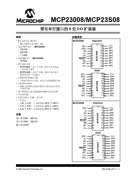
19 I/O 双向 I/O 引脚。可被使能用于电平变化中断和 / 或内部弱上拉电阻器。
18
20
P 电源。
N/C
10, 11
2006 Microchip Technology Inc.
DS21919B_CN 第 3 页
MCP23008/MCP23S08
1.2 上电复位 (POR)
在 VDD 上升到足以禁止 POR 电路 (即,将器件从复位 状态释放)的电压之前,片上的 POR 电路将使器件保持 在复位状态。最大 VDD 上升时间在第 2.0 节 “电气特 性”中指定。
2006 Microchip Technology Inc.
DS21919B_CN 第 5 页
MCP23008/MCP23S08
1.4.1
对 I2C 器件寻址 (MCP23008)
83832中文资料
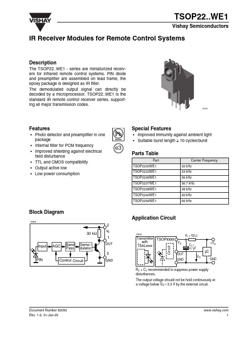
Document Number IR Receiver Modules for Remote Control SystemsDescriptionThe TSOP22..WE1 - series are miniaturized receiv-ers for infrared remote control systems. PIN diode and preamplifier are assembled on lead frame, the epoxy package is designed as IR filter.The demodulated output signal can directly be decoded by a microprocessor. TSOP22..WE1 is the standard IR remote control receiver series, support-ing all major transmission codes.Features•Photo detector and preamplifier in one package•Internal filter for PCM frequency•Improved shielding against electrical field disturbance•TTL and CMOS compatibility •Output active low•Low power consumptionSpecial Features•Improved immunity against ambient light •Suitable burst length ≥ 10 cycles/burstParts TableBlock DiagramApplication CircuitPartCarrier Frequency TSOP2230WE130 kHz TSOP2233WE133 kHz TSOP2236WE136 kHz TSOP2237WE136.7 kHz TSOP2238WE138 kHz TSOP2240WE140 kHz TSOP2256WE156 kHz Document Number 82092Absolute Maximum RatingsAbsolute Maximum RatingsT amb = 25°C, unless otherwise specifiedElectrical and Optical CharacteristicsT amb = 25°C, unless otherwise specifiedParameterTest conditionSymbol Value Unit Supply Voltage (Pin 2)V S - 0.3 to + 6.0V Supply Current (Pin 2)I S 5mA Output Voltage (Pin 1)V O - 0.3 to + 6.0V Output Current (Pin 1)I O 5mA Junction Temperature T j 100°C Storage T emperature Range T stg - 25 to + 85°C Operating Temperature Range T amb - 25 to + 85°C Power Consumption (T amb ≤ 85°C)P tot 50mW Soldering Temperaturet ≤ 5 s T sd260°CParameterTest conditionSymbol Min Typ.Max Unit Supply Current (Pin 2)V S = 5 V , E v = 0I SD 0.81.2 1.5mA V S = 5 V , E v = 40 klx, sunlightI SH 1.5mA Supply Voltage (Pin 2)V S 4.55.5V Transmission Distance E v = 0, test signal see fig.1, IR diode TSAL6200, I F = 250 mA d 35m Output Voltage Low (Pin 1)I OL = 0.5 mA, E e = 0.7 mW/m 2, f = f oV OL 250mV Minimum Irradiance (30 - 40 kHz)Pulse width tolerance: t pi - 6/f o < t po < t pi + 5/f o , test signal see fig.1E e min0.20.5mW/m 2Minimum Irradiance (56 kHz)Pulse width tolerance: t pi - 6/f o < t po < t pi + 5/f o , test signal see fig.1E e min0.30.7mW/m 2Maximum Irradiance t pi - 5/f o < t po < t pi + 6/f o E e max 30W/m 2DirectivityAngle of half transmission distanceϕ1/2± 45degDocument Number Typical Characteristics (Tamb = 25 °C unless otherwise specified)Figure 1. Output Function Figure 2. Pulse Length and Sensitivity in Dark Ambient Figure 3. Output Function E eV O V V 0.00.10.20.30.40.50.60.70.80.91.00.11.010.0100.01000.010000.0E e – Irradiance ( mW/m 2 )16908t – O u t p u t P u l s e W i d t h ( m s )po E eV O V V OLFigure 4. Output Pulse DiagramFigure 5. Frequency Dependence of ResponsivityFigure 6. Sensitivity in Bright AmbientT ,T – O u t p u t P u l s e W i d t h ( m s )0.00.10.20.30.40.50.60.70.80.91.00.11.010.0100.01000.010000.0E e – Irradiance ( mW/m 2 )16909on o f f 0.70.91.11.3f/f 0 – Relative Frequency169250.00.51.01.52.02.53.03.54.00.010.101.0010.00100.00E – Ambient DC Irradiance (W/m 2)16911E – T h r e s h o l d I r r a d i a n c e ( m W /m )em i n 2 Document Number 82092Figure 7. Sensitivity vs. Supply Voltage Disturbances Figure 8. Sensitivity vs. Electric Field Disturbances Figure 9. Max. Envelope Duty Cycle vs. Burstlength0.1 1.010.0100.01000.0D V sRMS – AC Voltage on DC Supply Voltage (mV)16912E – T h r e s h o l d I r r a d i an c e ( m W /m )0.00.40.81.21.60.00.40.81.22.0E – Field Strength of Disturbance ( kV/m )2.094 81471.6em i n 20.00.10.20.30.40.50.60.70.8020406080100120Burst Length ( number of cycles / burst )16913M a x . E n v e l o p e D u t y C y c l eFigure 10. Sensitivity vs. Ambient TemperatureFigure 11. Relative Spectral Sensitivity vs. WavelengthFigure 12. Directivity–30–150153045607590T amb – Ambient T emperature (q C )16918E – T h r e s h o l d I r r a d i a n c e ( m W /m )em i n 275085095010501150λ-Wavelength (nm )16919S ()-R e l a t i v e S p e c t r a l S e n s i t i v i t yλr e l 96 12223p20.40.200.20.40.60.60.90q 30q10q 20q40q50q 60q 70q 80q1.00.80.7d rel – Relative Transmission DistanceDocument Number Suitable Data FormatThe circuit of the TSOP22..WE1 is designed in that way that unexpected output pulses due to noise or disturbance signals are avoided. A bandpass filter, an integrator stage and an automatic gain control are used to suppress such disturbances.The distinguishing mark between data signal and dis-turbance signal are carrier frequency, burst length and duty cycle.The data signal should fulfill the following conditions:• Carrier frequency should be close to center fre-quency of the bandpass (e.g. 38 kHz).• Burst length should be 10 cycles/burst or longer.• After each burst which is between 10 cycles and 70cycles a gap time of at least 14 cycles is necessary.• For each burst which is longer than 1.8 ms a corre-sponding gap time is necessary at some time in the data stream. This gap time should be at least 4 times longer than the burst.• Up to 800 short bursts per second can be received continuously.Some examples for suitable data format are: NEC Code, Toshiba Micom Format, Sharp Code, RC5Code, RC6 Code, R-2000 Code.When a disturbance signal is applied to the TSOP22..WE1 it can still receive the data signal.However the sensitivity is reduced to that level that no unexpected pulses will occur.Some examples for such disturbance signals which are suppressed by the TSOP22..WE1 are:• DC light (e.g. from tungsten bulb or sunlight)• Continuous signal at 38 kHz or at any other fre-quency• Signals from fluorescent lamps with electronic bal-last with high or low modulation ( see Figure 13 or Fig-ure 14 ).Figure 13. IR Signal from Fluorescent Lamp with low ModulationFigure 14. IR Signal from Fluorescent Lamp with high Modulation5101520Time ( ms )16920I R S i g n al5101520Time ( ms )16921I R S i g n alPackage Dimensions in mm Document Number 82092Ozone Depleting Substances Policy StatementIt is the policy of Vishay Semiconductor GmbH to1.Meet all present and future national and international statutory requirements.2.Regularly and continuously improve the performance of our products, processes, distribution andoperatingsystems with respect to their impact on the health and safety of our employees and the public, as well as their impact on the environment.It is particular concern to control or eliminate releases of those substances into the atmosphere which are known as ozone depleting substances (ODSs).The Montreal Protocol (1987) and its London Amendments (1990) intend to severely restrict the use of ODSs and forbid their use within the next ten years. Various national and international initiatives are pressing for an earlier ban on these substances.Vishay Semiconductor GmbH has been able to use its policy of continuous improvements to eliminate the use of ODSs listed in the following documents.1.Annex A, B and list of transitional substances of the Montreal Protocol and the London Amendmentsrespectively2.Class I and II ozone depleting substances in the Clean Air Act Amendments of 1990 by the EnvironmentalProtection Agency (EPA) in the USA3.Council Decision 88/540/EEC and 91/690/EEC Annex A, B and C (transitional substances) respectively. Vishay Semiconductor GmbH can certify that our semiconductors are not manufactured with ozone depleting substances and do not contain such substances.We reserve the right to make changes to improve technical designand may do so without further notice.Parameters can vary in different applications. All operating parameters must be validated for each customer application by the customer. Should the buyer use Vishay Semiconductors products for any unintended or unauthorized application, the buyer shall indemnify Vishay Semiconductors against all claims, costs, damages, and expenses, arising out of, directly or indirectly, any claim of personal damage, injury or death associated with such unintended or unauthorized use.Vishay Semiconductor GmbH, P.O.B. 3535, D-74025 Heilbronn, GermanyTelephone: 49 (0)7131 67 2831, Fax number: 49 (0)7131 67 2423Document Number 。
ul 2238标准的中文解读

ul 2238标准是什么?ul 2238标准是什么?”这是很多人都会问的一个问题。
对于大多数人来说,ul 2238标准是一个陌生的名词,甚至连基本的概念都不太清楚。
然而,对于一些行业内的专业人士来说,ul 2238标准是非常熟悉的一个词汇。
ul 2238标准是一种国际上通行的标准,它是由一个名为国际标准化组织(ISO)的国际组织制定的。
ul 2238标准被广泛应用于世界各个行业,尤其是一些特定的行业,比如电子、化工、机械等行业。
对于一些特定的产品或服务,ul 2238标准是非常重要的参考依据。
ul 2238标准的作用是什么?ul 2238标准具有很重要的作用。
ul 2238标准可以作为一种质量标准,它可以帮助企业或组织对产品或服务进行质量控制,以确保其达到一定的标准。
ul 2238标准可以作为一种行业标准,它可以帮助企业或组织了解行业内的发展趋势和规范,从而更好地制定发展战略和规划。
ul 2238标准的内容是什么?ul 2238标准的内容是非常丰富和复杂的。
具体来说,ul 2238标准包括了很多方面的内容,比如产品的设计、制造、测试和质量控制等方面。
ul 2238标准还包括了很多具体的技术要求和规范,比如产品的尺寸、材料、工艺等方面的要求。
ul 2238标准对产品的品质和性能都有着非常严格和细致的要求。
如何理解ul 2238标准?要理解ul 2238标准,并不是一件容易的事情。
因为ul 2238标准的内容和要求都非常繁琐和专业,需要有一定的专业知识和经验才能够理解。
对于一般的消费者来说,他们可以通过一些权威的渠道来了解ul 2238标准,比如一些相关的行业协会、专业媒体等。
他们还可以通过一些权威的认证机构和测试机构来了解ul 2238标准的具体要求。
ul 2238标准是一种国际上通行的质量标准,它具有很重要的作用。
对于一些特定的产品或服务来说,ul 2238标准是非常重要的参考依据。
不过,要理解ul 2238标准,并不是一件容易的事情,需要有一定的专业知识和经验才能够理解。
AMS1117 SOT223 中文资料
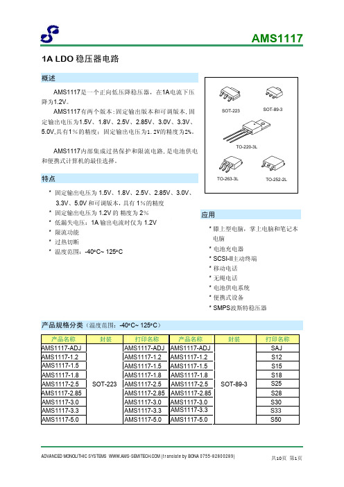
推荐工作条件
参数 输入电压 工作结温范围
符号 VIN TJ
范围 15
-40 ~ +125
单位 V °C
电气特性(除非特别指定,否则黑色字体所示的参数,Tamb=25°C,正常工作结温范围 -40°C ~125°C。)
参数 基准电压
输出电压
符号
测试条件
最小值 典型值 最大值 单位
AMS1117-ADJ,
0.5
%
Tamb=125°C, 1000Hrs
0. 3
%
% of VOUT, 10Hz≤f≤10kHz
0.003
%
SOT-223-3
120
TO-252-2
100
θJA TO-263-3
60
°C/W
SOT-89-3
165
TO-220-3
60
ADVANCED MONOLITHIC SYSTEMS (translate by BONA 0755-82800289)
PSRR fRIPPLE=120Hz, (VIN-VOUT)=3V, VRIPPLE=1VPP
6 12 mV 1.00 1.20 1.05 1.25 V 1.10 1.30
5 10 mA
60 75
dB
Iadj
60 120 μA
0≤ IOUT≤1A, 1.4V ≤VIN-VOUT≤10V
0.2 5 μA
AMS1117内部集成过热保护和限流电路,是电池供电 和便携式计算机的最佳选择。
SOT-223
SOT-89-3
TO-220-3L
特点
TO-263-3L
TO-252-2L
* 固定输出电压为 1.5V、1.8V、2.5V、2.85V、3.0V、 3.3V、5.0V 和可调版本,具有 1%的精度
Philips一体化多功能煮沸器用户手册说明书

HD2238User manual• Always put the inner pot in the appliance before you put the plug in the power outlet and switch it on.• Do not place the inner pot directly over an open fire to cook food.• Do not use the inner pot if it is deformed.• Make sure that the sealing ring is clean and in good condition.• The accessible surfaces may become hot when the appliance is operating. Take extra caution when touching the surfaces.• Beware of hot steam coming out of the floating valve and pressure regulator valve during cooking or when you open the lid. Keep hands and face away from the appliance to avoid the steam.• Do not lift and move the appliance while it is operating.• Do not exceed the maximum water level indicated in the inner pot to prevent overflow.• Do not place the cooking utensils inside the pot while cooking.• Only use the cooking utensils provided. Avoid using sharp utensils.• To avoid scratches, itis not recommendedto cook ingredients with crustaceans and shellfish. Remove the hard shells before cooking.• Do not place a magnetic substanceon the lid. Do not use the appliance near a magnetic substance.• Always let the appliance cool downto room temperature before you clean or move it.• Always clean theappliance after use. Donot clean the appliancein dishwasher.• Always unplug theappliance if not usedfor a longer period.• If the appliance isused improperly orfor professional orsemi-professionalpurposes, or if it isnot used accordingto the instructions inthis safety leaflet, theguarantee becomesinvalid and Philipsrefuses liability for anydamage caused.• Visit /support to downloadthe user manual.Electromagnetic fields (EMF)This appliance complies with the applicablestandards and regulations regarding exposure toelectromagnetic fields.2 What’s in the box (fig. 1)Main unit Power cordRice & Soup ladle Steaming plateMeasuring cup Glass lidUser manual Recipe bookletWarranty card3 Overview (fig. 1)Product overviewa Lid handle h Control Panelb Top lid i Heating elementc Detachable inner lid j Power socketd Sealing ring k Locking pineWater levelindications l Floaterf Side handle m Pressure regulatorg Inner pot n Safety valveControls overviewo Heating indicator z Increase buttonp Power indicator{Cooking time buttonqKeep warm/Cancelbutton|Bake buttonr Slow cook button }Yogurt buttons Sauté/sear button ~Kaya buttontSauce thickeningbutton Display panelu Fried rice button€Stew buttonv Preset time button Start/Reheat buttonw Decrease button‚Keep warm indicatorxTemperature/Pressure indicatorƒMaintain pressureindicatoryTemperature/Pressure button…Start pressureindicatorFunctions overviewPressure cooking functionsCookingfunctionDefaultpressurekeeping time(minute)Pressure keepingtime regulatingrange (minute)Soup2020-59Porridge1515-59Rice14Not adjustableSteam83-20Chicken/Duck1515-59Beaf/Lamb3030-59Beans/Tendons3030-59Normal cooking functions(non-pressure)CookingfunctionDefaultcooking timeCooking timeregulating rangeSlow cook 6 hours 2 - 12 hoursSauté/sear(low /mid/hightemperature)3 minutes 2 - 59 minutesSaucethickening(low /mid/hightemperature)8 minutes 5 - 59 minutesFried rice11 minutes7 - 59 minutesBake45 minutes10 - 59 minutesYogurt8 hours 6 - 12 hoursKaya18 minutes 5 - 59 minutesStew 1 hour35 minutes -10 hoursReheat25 minutes20 - 59 minutes4 Using the All-in-one MultiCookerBefore first use1 Remove all packaging materials from theappliance.2 Take out all the accessories from the inner pot.3 Clean the parts of the All-in-one Multi Cookerthoroughly before using it for the first time (seechapter "Cleaning and Maintenance").Note•Make sure all parts are completely dry beforeyou start using the All-in-one Multi Cooker.Preparations before cooking(fig. 2)Before using the All-in-one Multi Cooker to cookfood, follow below preparation steps:1 Hold the lid handle and turn it anti-clockwiseuntil the top lid cannot move any more, then liftup the top lid.2 Take out the inner pot from the All-in-one MultiCooker and put the pre-washed food in the innerpot.3 Wipe the outside of the inner pot dry, then put itback into the All-in-one Multi Cooker.4 Place the top lid onto the All-in-one MultiCooker and turn it clockwise. You will hear a“click” sound when the top lid is properly locked.Note•Make sure the sealing ring is properlyassembled around the edge of the detachableinner lid.•Make sure the pressure regulator valve andfloating valve are clean and not blocked.•Make sure the outside of the inner pot is dryand clean, and that there is no foreign residueon the heating element.•Make sure the inner pot is in proper contactwith the heating element.Cooking food (fig. 3)Note•Do not fill the inner pot with less than 1/3 ormore than 2/3 full of food and liquid.•For food that expands during cooking, do notfill the inner pot with more than 1/2 full of foodand liquid.•For rice cooking, follow the water levelindications on the inside of the inner pot. Youcan adjust the water level for different types ofrice and according to your own preference. Donot exceed the maximum quantities indicatedon the inside of the inner pot.•Make sure the floater on the top lid dropsdown before cooking.•After the cooking process is started, you canpress Cancel/Warm to deactivate the currentwork, and the appliance goes to standbymode.Pressure cooking1 Follow the steps in “Preparations beforecooking”.2 Turn the pressure regulator to seal.3 Put the plug in the power socket.»The power indicator starts flashing.4 Press Pressure cook to choose one of thepressure cooking functions - Soup, Porridge,Rice, Steam, Chicken/Duck, Beaf/Lamb orBeans/Tendons.»The default pressure keeping time is displayedon the screen.Note•The pressure keeping time is not adjustablefor Rice.•You can adjust the pressure(Low. High) bypressing the Temp/kPa button.•When cooking 2 cups of rice (small amount),for better result, spread the rice evenly in theinner pot before cooking.•When cooking 14 cups of rice (maximumamount), the bottom layer of rice may getovercooked.5 To set a different pressure keeping time, pressCooking time.6 Press or to set the pressure keeping time.7 Press Start/Reheat to start the cooking process.8 When the All-in-one Multi Cooker reaches theworking pressure:»Maintain Pressure lights up;9 When the pressure keeping time has elapsed,the All-in-one Multi Cooker automaticallyswitches to keep warm mode.»The keep warm indicator (Keep warm) lightsup.10 Turn the pressure regulator to vent.»The All-in-one Multi Cooker starts releasingpressure.»The floater drops down when the pressure isreleased sufficiently.11 Hold the top lid handle and turn the lid anti-clockwise until it cannot move any more, then liftit up.Note•When cooking soup or viscous liquid, donot release pressure by turning the pressureregulator to vent, otherwise liquid might spurtfrom the pressure regulator valve. Wait untilthe pressure is naturally released and thefloater has dropped down to open the top lid.•The pressure keeping timer will start countingdown when the working pressure is reached.•After the cooking is finished and the pressureis released, you can press the cancel button(Warm/Cancel) and unplug the All-in-oneMulti Cooker to turn off the keep warmfunction or when not in use.Normal cookingNote•For normal cooking, you can cook foodwithout adding water in the inner pot. In thiscase, make sure to turn the pressure regulatorto bake.•Make sure to keep the top lid open for theentire time when you cook food in the Sauté/sear mode.•To choose the Reheat function, press Start/Reheat when the appliance is in standbymode.•You can press the Temp/kPa button to adjusttemparature (Low, Mid, High) for the followingfunctions: Sauté/sear and Sauce thickening.•The glass lid shall be used for non-pressurecooking functions.To cook food with normal pressure, press thecooking buttons and choose Slow cook, Sauté/sear, Fried rice, Sauce thickening, Stew, Yogurt,Kaya or Bake.1 Follow the steps in “Preparations beforecooking”.2 Turn the pressure regulator to bake or seal.• For Slow cook, Stew and Yogurt, turn thepressure regulator to seal.• For Bake, turn the perssure regulator to bake.3 Put the plug in the power socket.»The power indicator (Power) starts flashing.4 Press the desired cooking function button tochoose a cooking mode.5 To set a different cooking time, press Cookingtime.»The cooking time flashes on the screen.6 Press or to set the cooking time.7 Press Start/Reheat to start the cooking process.8 When the cooking time has elapsed, the All-in-one Multi Cooker automatically switches to keepwarm or standby mode.9 Turn the pressure regulator to vent.10 Hold the top lid handle and turn the lid anti-clockwise until it cannot move any more, then liftit up.Preset time for delayed cooking(fig.4)You can preset the delayed cooking time fordifferent cooking functions. The preset timer isavailable up to 24 hours.1 After the cooking function is selected, pressPreset timer.»The hour unit starts flashing on the display.2 Press or to set the hour unit.3 After the hour unit is set, press Preset timeragain.»The minute unit starts flashing on the display.4 Press or to set the minute button.5 Press Preset timer to confirm the preset time.6 Press Start/Reheat to start the cooking process.7 When the preset time has elapsed, the All-in-one Multi Cooker starts working automatically.Note•The preset function is not available in thefollowing modes: Sauté/Sear (both low andhigh temperatures), Reheat and Warm.Assembling and disassemblingthe pressure regulatorWarning•Do not disassemble the pressure regulatorduring cooking. Always unplug the All-in-oneMulti Cooker and wait until the pressure hasbeen released sufficiently to do so.• To disassemble the pressure regulator:1 Turn the lower screw anticlockwise until itbecomes loose.2 Pull it up and take out the pressure regulator.• To assemble the pressure regulator:1 Assemble the lower screw back to the regulator.2 Make sure the regulator points at the sealedposition ( ) and put it back to the steam valve.3 Turn the screw clockwise until it is fastened.5 Cleaning andMaintenanceNote•Unplug the All-in-one Multi Cooker beforestarting to clean it.•Wait until the All-in-one Multi Cooker hascooled down sufficiently before cleaning it.InteriorInside of the top lid, glass lid, and the main body:• Wipe with wrung out and damp cloth.• Make sure to remove all the food residuesstuck to the All-in-one Multi Cooker.Heating element:• Wipe with wrung out and damp cloth.• Remove food residues with wrung out anddamp cloth.Sealing ring:• Soak in warm water and clean with sponge.Inner lid:• Remove the detachable inner lid. Soak it inwarm water and clean with sponge.ExteriorSurface of the top lid, glass lid and outside of themain body:• Wipe with a cloth damped with soap water.• Only use soft and dry cloth to wipe the controlpanel.• Make sure to remove all the food residuesaround the pressure regulator valve andfloating valve.Pressure regulator valve and floating valve:• Disassemble the pressure regulator, soak it inwarm water, and clean with sponge.• Remove food residues in the pressureregulator valve and floating valve.AccessoriesMeasuring cup, rice & soup ladle, and inner pot:• Soak in hot water and clean with sponge.6 SpecificationsModel Number HD2238Rated voltage220-240VRated frequency50-60HzRated power input1370-1630WRated capacity8.0LWarm keeping temperature60-80°CNote•Always unplug the appliance if not used for alonger period.7 RecyclingDo not throw away the product with the normalhousehold waste at the end of its life, but hand it inat an official collection point for recycling. By doingthis, you help to preserve the environment.Follow your country's rules for the separatecollection of electrical and electronic products.Correct disposal helps prevent negativeconsequences for the environment and humanhealth.8 Warranty and supportVersuni offers a two-year warranty after purchaseon this product. This warranty is not valid if a defectis due to incorrect use or poor maintenance. Ourwarranty does not affect your rights under law as aconsumer. For more information or for invoking thewarranty, please visit our website/support.9 TroubleshootingIf your All-in-one Multi Cooker does not function properly or if the cooking quality is insufficient, consult thetable below. If you are unable to solve the problem, contact a Philips service center or the Consumer CareCenter in your country.Problem Cause SolutionI have difficultiesopening the lid aftercooking.Need to release thepressure.PressureControl ValveFloater bakeventsealSet the pressure control valve to 'Vent'.And wait until the floater has dropped.Floater stuck in upposition.Set the pressure control valve to 'Vent'.And wait until the floater has dropped.I have difficultiesclosing the top lid.The sealing ring is not wellassembled.Make sure the sealing ring is well assembledaround the inside of the top lid.The floater stuck in upposition.The floater blocks the locking pin. Push down thefloater so that it does not block the locking pin.Leaking from under lid.Sealing ring missing.Sealing ringInner lidSealing ringInner lidPut sealing ring in place correctly on inner lid.Food or debris undersealing ring.Remove the sealing ring, clean and replace.Lid not correctly closed.Open and reclose the lid, checking for correctclosing.The pressure level insideof the appliance isabnormal.In this case the safety valve will be releasingsteam. Take the appliance to your Philips dealeror a service center authorized by Philips.Leaking from floaterSealing ring broken.Replace the sealing ring.Food or debris undersealing ring.Remove the sealing ring, clean and replace.Floater does not riseup after the appliancestarts pressurizing.Food&water are belowminimum level.Add food/water. Make sure there is enough foodand water in the inner pot.Leaking from lid orpressure control valve.Take the appliance to a Philips service dealer.E3 displays on thescreen.The temperature insidethe inner pot is too high.Wait until it falls down to room temperature.E1, E2, or E4 displayson the screen.The All-in-one MultiCooker has malfunction.Take the appliance to a Philips service center.。
TOP223开关电源实际应用
TOP223开关电源实际应用工欲善其事,必先利其器。
无论做什么电子设计项目,首先要有一个稳定可靠的电源作为支撑,电源的负载能力,波纹差,波动噪声,直接关乎电路性能的好坏。
为了制作一款功率足够,性能优良的开关电源,经过查阅资料,PI公司的TOP223芯片以及其应用电路成为了我们的主要选择对象。
首先,来隆重介绍一下我们的主角——TOP223Y。
TOP223Y其脚功能及工作原理如下:D脚(3脚)内连功率开关管N沟MOSFET的漏极、开关电流限流比较器、启动用高压电流源Ih.b等。
C脚(1脚)是唯一的控制端。
这是控制占空比改变的误差放大器和反馈电流输入端,内连并联稳压调整提供正常工作时内偏置电流,也是过压保护“锁存关闭”的触发输入,还用作高路补偿外接电容器连接点。
C脚(1脚)正常最小偏置电流约2.5mA,小至1.2mA时就会进入自动再启动待式模式,上冲达45mA,就使过压保护起作用,令开关进入重复动作(自动再启动)模式,并且TOP开关内N-MOSFET截止(关闭)保护。
C脚(1脚)电压下拉到开机复位阈值(约3.3V±1V)以下,然后才能转入正常开机工作状态。
S脚(2脚)连接功率开关管N沟MOSFET的源极,也是开关电流返回端,内电路及原边电路公共接地或参考点。
A1用于过压过热保护“锁存关闭”,由开机复位电路复零开启。
A2用于限流锁存及前沿空白和最小导通延时控制,由每周期开始的时钟脉冲CK开启置位,正常工作时由PWM比较器输出复位。
内振荡时钟发生器100kHz时钟脉冲CK,还产生出PWM锯齿波SA以及最大占空比控制信号DM。
其功能包括功率MOSEFT、脉宽调制器、高压启动电路、环路补偿和故障自动保护电路。
TOP223只需要配合很少量的外部元件,与光电耦合器配合使用,便可快速设计出一款性能参数足够好的大功率开关电源。
下面使我们参考的关于TOP223开关电源设计的几篇比较好的文章【设计实例】TOP223Y开关电源设计实例分享基于TOP223Y多路单端反激式开关电源的设计方案在选择元件参数时,最重要的是高频变压器的选择与绕组参数的确定,参考前人经验有以下几种组合比较合适。
- 1、下载文档前请自行甄别文档内容的完整性,平台不提供额外的编辑、内容补充、找答案等附加服务。
- 2、"仅部分预览"的文档,不可在线预览部分如存在完整性等问题,可反馈申请退款(可完整预览的文档不适用该条件!)。
- 3、如文档侵犯您的权益,请联系客服反馈,我们会尽快为您处理(人工客服工作时间:9:00-18:30)。
Photo Modules for PCM Remote Control Systems Available types for different carrier frequenciesTypeTSOP2230TSOP2236TSOP2238TSOP2256DescriptionThe TSOP22.. – series are miniaturized receivers forinfrared remote control systems. PIN diode andpreamplifier are assembled on lead frame, the epoxypackage is designed as IR filter.The demodulated output signal can directly bedecoded by a microprocessor. The main benefit is thereliable function even in disturbed ambient and theprotection against uncontrolled output pulses.UnitVmAVmA°C°C°CmW°CMax Unit 1.5mAmA 5.5VDocument Number 82095Suitable Data FormatThe circuit of the TSOP22... is designed in that way that unexpected output pulses due to noise or disturbance signals are avoided. A bandpassfilter, an integrator stage and an automatic gain control are used to suppress such disturbances.The distinguishing mark between data signal and disturbance signal are carrier frequency, burst length and duty cycle.The data signal should fullfill the following condition:•Carrier frequency should be close to center frequency of the bandpass (e.g. 38kHz).•Burst length should be 10 cycles/burst or longer.•After each burst which is between 10 cycles and 70cycles a gap time of at least 14 cycles is neccessary.•For each burst which is longer than 1.8ms a corresponding gap time is necessary at some time in the data stream. This gap time should be at least 4times longer than the burst.•Up to 800 short bursts per second can be received continuously.Some examples for suitable data format are:NEC Code, Toshiba Micom Format, Sharp Code, RC5Code, RC6 Code, R–2000 Code.When a disturbance signal is applied to the TSOP22...it can still receive the data signal. However the sensitivity is reduced to that level that no unexpected pulses will occure.Some examples for such disturbance signals which are suppressed by the TSOP22... are:•DC light (e.g. from tungsten bulb or sunlight)•Continuous signal at 38kHz or at any other frequency•Signals from fluorescent lamps with electronic ballast with high or low modulation (see Figure A or Figure B).05101520time [ms]Figure A: IR Signal from Fluorescent Lamp with low Modulation05101520time [s]Figure B: IR Signal from Fluorescent Lamp with high Modulation2.0/m ) Figure 4. Sensitivity vs. Electric Field Disturbances1 kHzE eV O V OH V OL Optical Test Signal (IR diode TSAL6200, I Output Signalt d1)E eOptical Test Signal Document Number 82095Dimensions in mm13655Document Number 82095Ozone Depleting Substances Policy StatementIt is the policy of Vishay Semiconductor GmbH to1.Meet all present and future national and international statutory requirements.2.Regularly and continuously improve the performance of our products, processes, distribution and operating systems with respect to their impact on the health and safety of our employees and the public, as well as their impact on the environment.It is particular concern to control or eliminate releases of those substances into the atmosphere which are known as ozone depleting substances (ODSs).The Montreal Protocol (1987) and its London Amendments (1990) intend to severely restrict the use of ODSs and forbid their use within the next ten years. Various national and international initiatives are pressing for an earlier ban on these substances.Vishay Semiconductor GmbH has been able to use its policy of continuous improvements to eliminate the use of ODSs listed in the following documents.1.Annex A, B and list of transitional substances of the Montreal Protocol and the London Amendments respectively2.Class I and II ozone depleting substances in the Clean Air Act Amendments of 1990 by the Environmental Protection Agency (EPA) in the USA3.Council Decision 88/540/EEC and 91/690/EEC Annex A, B and C (transitional substances) respectively.Vishay Semiconductor GmbH can certify that our semiconductors are not manufactured with ozone depleting substances and do not contain such substances.We reserve the right to make changes to improve technical design and may do so without further notice.Parameters can vary in different applications. All operating parameters must be validated for each customer application by the customer. Should the buyer use Vishay-Telefunken products for any unintended or unauthorized application, the buyer shall indemnify Vishay-Telefunken against all claims, costs, damages, and expenses, arising out of, directly or indirectly, any claim of personal damage, injury or death associated with such unintended or unauthorized use.Vishay Semiconductor GmbH, P .O.B. 3535, D-74025 Heilbronn, Germany Telephone: 49 (0)7131 67 2831, Fax number: 49 (0)7131 67 2423。
