Autodesk Revit Architecture软件在教学中的运用
Autodesk Revit 土建应用项目教程第三章

• (1)选择任意一根轴网线,单击标头外侧方框,即可关闭/ 打开轴号 显示。
• (2)如需控制所有轴号的显示,可选择所有轴线自动激活“修改│ 轴网”选项卡。在“属性”面板中选择“编辑类型”命令,弹出“类 型属性”对话框,在其中修改类型属性参数,单击端点默认编号的 “√”标记,如图3-17 所示。
• 3.2.4 尺寸驱动调整轴线位置
• 选择任何一根轴网线,会出现蓝色的临时尺寸标注,单击尺寸即可修 改其值,调整轴线位置,如图3-15 所示。
上一页 下一页 返回
3.2 项目轴网创建
• 3.2.5 轴网标头位置调整
• 选择任何一根轴网线, 所有对齐轴线的端点位置会出现一条对齐虚 线,用鼠标拖曳轴线端点,所有轴线端点都将同步移动。
F3),在F2 与F3 之间会显示一条蓝色临时尺寸标注,单击临时尺寸 标注上的数字,重新输入新的数值并按回车键,即可完成标高高度的 调整,如图3-4 所示(标高高度距离的单位为mm)。
上一页 下一页 返回
3.1 项目标高创建
• 3.1.2 复制、阵列标高
• 选择二层标高F2,选择“修改│标高”选项卡,然后在“修改”面板 中选择“复制” 或“阵列”命令,可以快速生成所需标高。
3.2 项目轴网创建
• 3.2.7 轴号偏移
• 单击标头附近的“添加弯头” 符号,单击“拖曳点”并按住鼠标不 放, 调整轴号位置, 如图3-20 所示。
• 偏移后若要恢复直线状态,单击后拖动“拖曳点”到直线上释放鼠标 即可。
• 【注意】轴网锁定状态下要取消偏移,需要选择轴线并取消锁定后, 才能移动“拖曳点”。
• (1)如果只需移动单根轴线的端点, 则先打开对齐锁定,再拖曳轴 线端点。
Autodesk Revit 土建应用项目教程第八章

图8-7
返回
图8-8
返回
图8-9
返回
图8-10
返回
图8-11
返回
图8-12
返回
图8-13
返回
图8-14
返回
图8-15
返回
图8-16
返回
图8-17
返回
图8-18
返回
图8-19
返回
图8-20
返回
图8-21
返回
图8-22
返回
图8-23
返回
图8-24
返回
• (2)框架立面的生成。创建拉伸屋顶时经常需要创建一个框架立面, 以便于绘制屋顶的截面线。
• 在“视图”选项卡“创建”面板的“立面” 下拉列表中选择“框架 立面”选项,点选轴网或命名的参照平面,放置立面符号。
• 项目浏览器中自动生成一个“立面1-a”视图,如图8-16 所示。
上一页 下一页 返回
8.1 屋顶创建
• 在“建筑”选项卡“构建”面板中单击“幕墙网格”按钮分割玻璃, 用“竖梃”命令添加竖梃,如图8-18 所示。
• 8.1.4 特殊屋顶
• 对于造型比较独特、复杂的屋顶,用户可以在位创建屋顶族。 • 在“建筑”选项卡“创建”面板中“构件”下拉列表中选择“内建模
型”选项, 在弹出的“族类别和族参数”对话框中选择族类别为 “屋顶”,输入名称进入创建族模式。
”符
号将出现在其上方,单击角度值设置屋面坡度。单击完成绘制, 如
图8-5 所示。
上一页 下一页 返回
8.1 屋顶创建
• 3.四面双坡屋顶 • 在“建筑”选项卡“构建”面板的“屋顶”下拉列表中选择“迹线屋
顶”选项,进入绘制屋顶轮廓草图模式。 • 在选项栏取消勾选“定义坡度”复选框, 用“拾取墙”或“线”命
Autodesk Revit 土建应用项目教程第十一章

返回
11.4 创建散水
• (1)在“建筑”选项卡“构建”面板中单击“墙”按钮,在“属性” 面板中单击“编辑类型”按钮,弹出“类型属性”对话框,如图1115 所示。
• (2)在“类型属性”对话框中单击“结构”参数后面的“编辑”按 钮,弹出“编辑部件”对话框,在对话框中单击左下侧的“预览”按 钮,打开预览后将“视图”改成“剖面:修改类型属性”,如图1116 所示。
卡“放置”面板中选择“重新放置墙饰条”选项。将鼠标移到墙上所 需的位置, 单击以放置墙饰条。
下一页 返回
11.1 创建墙饰条及分隔条
• (7)要完成墙饰条的放置, 可单击“修改”按钮, 如图11-1 所示。
• 11.1.2 创建分隔条
• (1)打开三维视图或立面视图。 • (2)在“建筑”选项卡“构建”面板的“墙”下拉列表中选择“墙:
19 所示。
返回
图11-1
返回
图11-2
返回
图11-3
返回
图11-4
返回
图11-5
返回
图11-6
返回
图11-7
返回
图11-8
返回
图11-9
返回
图11-10返回图11-1返回图11-12
返回
图11-13
返回
图11-14
返回
图11-15
返回
图11-16
返回
图11-17
返回
图11-18
返回
图11-19
返回
下一页 返回
11.2 创建屋顶檐口
• 2.封檐板 • 在“建筑”选项卡“构建”面板的“屋顶”下拉列表中选择“屋顶:
封檐板”选项, 自动激活“修改│放置封檐板”选项卡,进入绘制轮 廓线草图模式。 • 单击拾取屋顶的边缘线,自动以默认的轮廓样式生成“封檐板”,单 击“当前完成” 按钮完成绘制,如图11-6 所示。 • 在立面视图中选择屋檐底板,修改“实例属性”参数为“设置轮廓的 垂直水平轮廓偏移”,设置屋檐底板与屋顶的相对位置、轮廓的角度 值、轮廓样式及封檐板的材质显示,如图11-7 所示。 • 选择已创建的封檐板,软件自动跳转到“修改│封檐板”选项卡,在 “屋顶封檐板” 面板中可以选择“添加/ 删除线段”或“修改斜接” 选项,修改斜接的方式有“垂直”“水平”“垂足”三种方式,如图 11-8 所示。
Autodesk Revit 土建应用项目教程第九章

9.2 楼梯
• 【提示】 • (1)绘制梯段时,是以梯段中心为定位线来开始绘制的。 • (2)根据不同的楼梯形式:单跑、双跑L 形、双跑U 形、三跑楼梯
等,绘制不同数量、位置的参照平面以方便楼梯精确定位,并绘制相 应的梯段,如图9-10 所示。 • 2.用边界和踢面命令创建楼梯 • (1)在“修改│创建楼梯草图”选项卡“绘制”面板中单击“边界” 按钮,分别绘制楼梯踏步和休息平台边界。 • 【注意】踏步和平台处的边界线需分段绘制,否则软件将把平台也当 成是长踏步来处理。
按钮,在弹出的“类型属性”对话框中使用“复制”命令,创建旋转 楼梯,并设置其属性:踏板、踢面、梯边梁等的高度,以及厚度尺寸、 材质、文字等。 • (3)在“属性”面板中设置楼梯宽度、基准偏移等参数,系统自动 计算实际的踏步高和踏步数。 • (4)单击“构件”面板下的“梯段”按钮,选择“圆心- 端点弧” 命令开始创建旋转楼梯。 • 捕捉旋转楼梯梯段的中心点、起点、终点位置绘制梯段,如图9-14 所示。
上一页 下一页 返回
9.1 扶手
• [ 切线连接] 如果两段相切扶手在平面内共线或相切,但没有垂直连 接,Revit 既可添加垂直或水平线段进行连接,也可不添加连接件但 保留间隙。这样即可在修改了平台处扶手高度,或扶手延伸至楼梯末 端之外的情况下创建光滑连接,如图9-7 所示。
• [ 扶手连接] 修剪、结合两种类型。如果要控制单独的扶手接点,可 以忽略整体的属性:选择扶手,单击“模式”面板中的“编辑路径” 按钮,进入编辑扶手草图模式,单击“工具”面板下的“编辑连接” 按钮,单击需要编辑的连接点,在选项栏的“扶栏连接” 下拉列表 中选择需要的连接方式,如图9-8 所示。
第9 章 扶手、楼梯及坡道的创建
Revit与CAD的区别、教学关联及Revit在高校的发展趋势
Revit与CAD的区别、教学关联及Revit在高校的发展趋势近几年,建筑信息模型(Building Information Modeling,BIM)技术在建筑行业掀起新的一波革新浪潮,为人类的生活与工作提供别样的便利,也真正实现了它存在的价值。
目前,BIM 技术在建筑行业涉及的范围极广,从项目建设初期的设计到施工模拟直至运营维护管理等,都能发挥BIM 的智能功效。
为了顺应市场的发展,高等教育也应随之而变,因此,BIM 相关软件的教学必不可少。
但是,迄今为止,仍然还是有许多建筑设计者在用传统的CAD(也叫AutoCAD)等软件来进行图纸设计。
然而简单的二维图形会使投标方和施工方都难以领会设计方的切实想法,而且在设计初期也不能看到最后的竣工效果,这就不便于在项目的中期阶段对方案进行实时优化,更不便于施工人员相互沟通与协助。
因此,建筑业要想迈上一条系统的、高效的、合理的发展道路,则必须引入多维可视化软件,相关的高校教育也应随之有所改变。
BIM 技术能够将项目建设过程中的相关信息进行具体的整合,并且应用到建筑相关领域以及项目建设的全生命周期的各个阶段。
目前,BIM 技术已经在国内外各个领域得到了广泛的应用与推广。
Autodesk Revit(后简称Revit)是美国Autodesk公司基于BIM 技术而开发的一种三维设计软件,该软件通过共享项目参数将模型内部的数据关联起来,使项目信息互通互融,得到更精确的结果。
2004 年,Autodesk 公司在中国推出了Autodesk Revit 的简体中文版,而CAD 则是早在20 世纪90 年代就入驻中国,而且目前国内的多数设计人员仍在使用的绘图软件。
CAD 无论是建筑制图还是机械制图都是二维模型,而Revit 是一种三维建模软件。
运用CAD 进行画图辅助并将其与Revit 的三维建模结合必将成为建筑领域的新的发展方向。
因此,目前,高校相关专业的教育教学方式也正在积极地朝着这一方向改革。
Autodesk Revit 土建应用项目教程第一章
• 1.1 BIM及参数化设计 • 1.2 Revit基本概念 • 1.3 Revit基本操作
1.1 BIM及参数化设计
• BIM 支持建筑师在施工前更好地预测竣工后的建筑,使他们在如今日 益复杂的商业环境中保持竞争优势。 Revit 软件专为建筑信息模型 (BIM)而构建。BIM 是以从设计、施工到运营的协调、可靠的项目 信息为基础而构建的集成流程。通过采用 BIM,建筑公司可以在整个 流程中使用一致的信息来设计和绘制创新项目,并且还可以通过精确 实现建筑外观的可视化来支持更好地沟通,模拟真实性能以便让项目 各方了解成本、工期与环境对项目的影响。
上一页 下一页 返回
1.1 BIM及参数化设计
• BIM 一般具有以下特征: • (1)可视化:即所见即所得。在BIM 建筑信息模型中,由于整个过
程都是可视化的, 所以,可视化的效果不仅可以用作效果图的展示 及报表的生成,更重要的是项目设计、建造、运营过程中的沟通、讨 论、决策都可在可视化的状态下进行。模拟三维的立体事物可使项目 在设计、建造、运营等整个建设过程可视化,方便进行更好的沟通、 讨论与决策。 • (2)协调性:当各专业项目信息出现“不兼容”现象时,如管道与 结构冲突,各个房间出现冷热不均,预留的洞口没留或尺寸不对等情 况,使用BIM 可有效协调流程进行协调综合,减少不合理变更方案或 者问题变更方案。
上一页 下一页 返回
1.1 BIM及参数化设计
• (3)模拟性:利用四维施工模拟相关软件,根据施工组织进度计划 安排,在已经搭建好的模型的基础上增加时间维度,分专业制作可视 化进度计划,即四维施工模拟。一方面可以指导现场施工,另一方面 为建设管理单位提供了非常直观的可视化进度控制管理依据。
试析revit软件在建筑制图课程中的实际应用

·26·当代教育实践与教学研究 作为土木工程专业的一门基础课程,建筑制图课程不仅要培养学生的绘图与读图能力,还要在教学过程中注重提高学生的空间想象力。
在传统的专业制图教学中,多以二维平面图形为教学基础,引导与培养学生的读图能力,但因为缺乏实践经验,学生的三维空间想象力难以建立,而且识图过程也相对比较难,因此降低了学生的学习兴趣。
随着近些年来BIM 技术在建筑领域的广泛应用,使revit 软件成为帮助学生识图的良好工具。
一、建筑制图课程的教学现状分析建筑制图课程在传统教学中是以二维投影图来表现的三维的立体图,这需要培养学生的空间思维能力,因此,在制图课程中难免存在一定的教学困难。
1.抽象的平面教学在以往的建筑制图课程中,往往是由老师在黑板上进行绘图讲解,引导学生完成专业图纸的解读,这既让学生感觉抽象、难懂,也难以建立三维立体的空间思维,无法达到教学的直观化与形象化,不能激发学生的学习兴趣,更无法调动学生的学习热情,对学生的创造性思维培养极为不利。
2.多媒体课件教学多媒体课件教学相对于传统教学,在一定程度上提高了教学效果与教学质量,也能发挥出学生的主体作用,但过多地依赖多媒体课件教学,也会产生一些不利因素。
一方面不利于学生的理解模仿,另一方面不利于教师的教学发挥。
这主要是由于多媒体课件是一个情节固定型的软件,它需要在课前进行制作,情节固定、内容封闭,因此,在实际课堂教学中,教师就变成了课件的解说员与放映员,但整个制图的构思与制作过程是无法展现出来的,这不仅不利于教师在教学中激情发挥,而且对学生的创造性培养也极为不利,制图过程没有示范性的效果,学生学习起来不仅难以理解,甚至模仿也极为困难,导致课后任务无法完成,使多媒体教学失去了教学优势。
3.AutoCAD 软件教学AutoCAD 是一个不断升级的版本,利用AutoCAD 软件创建的三维立体模型,不仅生动形象,而且能直观地表达出三维实体与二维视图之间的关系。
revit教程二RevitArchitecture初接触学习教案

同的门,推拉门,双开门,单开门;
第十四页,共36页。
Revit 基本(jīběn)术语
类型 簇是相关类型的集合,是类似几何图形的编组(biān zǔ)。 簇中的成员几何图形相似而尺寸不同。 类型可以看成簇的一种特定尺寸,也可以看成一种样式。 类型定义: 对象所具有的属性 定义对象与其它对象如何相互作用 定义对象如何把自己绘制成各种不同视图的表示方法。 各个簇可拥有不同的类型; 类型是簇的一种特定尺寸一个簇可以拥有多个类型; 每个不同的尺寸都可以是同一簇内的新类型;
变。反之,用户也可以通过改变注释图元的属性,从而改变模型的信息。
第8页/共35页
第九页,共36页。
Revit 基础知识
工作原理 首先用户创建项目; 其次用户往项目中添加参数化的建筑图元; 在Revit中,所有的建筑图元都视为类别,也就
是所说的”簇”; Revit根据(gēnjù)模型构件和注释图元对每个
为类型属性(shǔxìng)。 实例属性(shǔxìng):随着构件在建筑中或在项目中的位置变化而改变
的属性(shǔxìng)称为实例属性(shǔxìng)。
联系:“类”的继承属性(shǔxìng)。
第20页/共35页
第二十一页,共36页。
Revit 基本(jīběn)术语
实例(shílì)属性与类型属性的区别 类型属性影响全部在项目中该簇的实例(shílì)和任何要在项目中放置的实例
提示: 簇理解成”模具“,实例理解成”生成一个产品“; 与计算机专业的”类“”实例“联系理解;
第15页/共35页
第十六页,共36页。
Revit 基本(jīběn)术语
簇的分类 根据定义的方法和用途的不同,簇可分为系统簇、标准构件簇、内建簇。 系统簇 在Revit中预定义的簇,包括基本建筑构件。 可以在系统簇中通过设定新的参数来定义新的系统簇。 标准构件簇 在建筑设计中使用(shǐyòng)的标准尺寸和配置的常见构件和符号。 可以使用(shǐyòng)簇编辑器,标准簇样板来定义簇的几何图形和尺寸。 簇样板分两类: 基于主体的样板:如门簇,是基于墙主体的样板; 独立的样板:如柱、家俱等。 簇样板有助于创建和操作构件簇。
Autodesk Revit 土建应用项目教程第五章

• 按照上面的方法绘制办公楼一层建筑外墙和内墙,内墙类型及材质的 编辑方法同外墙,如图5-15 所示。
• 至此完成了办公楼一层外墙及内墙的构造定义,如图5-16 所示。二 层和三层的内外墙的绘制方法相同,这里不再重复介绍。
上一页 下一页 返回
5.1 墙体创建
• 5.1.3 叠层墙设置
• 选择“建筑”选项卡,单击“构建”面板下的“墙”按钮,从类型选 择器中选择叠层墙的类型,如“叠层墙:外部—带金属立柱的砌块上 的砖”类型,在“属性”面板中单击“编辑类型”按钮,弹出“类型 属性”对话框,再单击“结构”参数后的“编辑” 按钮,弹出“编 辑部件”对话框,如图5-13 所示。
• 同时,如需一次性还原已编辑过轮廓的墙体,可选择墙体,在“模式” 面板中单击“重设轮廓”按钮,即可实现。
• (5)附着/ 分离。选择墙体,自动激活“修改| 墙”选项卡,单击 “修改墙”面板下的“附着顶部/ 底部”按钮,然后拾取屋顶、楼板、 天花板或参照平面,可将墙连接到屋顶、楼板、天花板或参照平面上, 墙体形状自动发生变化。单击“分离顶部/ 底部”按钮可将墙从屋顶、 楼板、天花板或参照平面上分离开,墙体形状恢复原状,如图5-9 所 示。
上一页 下一页 返回
5.1 墙体创建
• 单击其中一个构造层,用“指定层”在左侧预览框中单击拆分开的某 个部分指定给该图层。用同样的操作设置完所有图层即可实现一面墙 在不同的高度有几个材质的要求,如图5-11 所示。
• 单击“墙饰条”按钮,弹出“墙饰条”对话框, 添加并设置墙饰条 的轮廓;如需新的轮廓,可单击“载入轮廓”按钮,从库中载入轮廓 族,单击“添加” 按钮可添加墙饰条轮廓,并设置其高度、放置位 置(墙体的顶部、底部,内部、外部)、与墙体的偏移值、材质及是 否剪切等设置,如图5-12 所示。
Autodesk Revit 土建应用项目教程第二章

2.2 项目图纸识读及处理
• 4.项目建筑立面图的识读 • 如图2-6~ 图2-9 所示,本建筑立面图的图名为①~⑧轴立面图、⑧~
①轴立面图、A ~ D轴立面图、D ~ A轴立面图,比例为1 ∶ 100,两 端的定位轴线编号分别为①轴和⑧轴;室内外高差为0.5 m,层高为 3.6 m,共有三层,局部两层,顶部有阁楼层,窗台高为0.9 m;在建 筑的主要出入口处设有一个悬挑雨篷,有一个三级台阶,该立面外形 规则,立面造型简单。
• 建筑施工图主要用来表达建筑设计的内容,即表示建筑物的总体布局、 外部造型、内部布置、内外装饰、细部构造及施工要求,主要包括首 页图、总平面图、建筑平面图、立面图、剖面图和建筑详图等。
下一页 返回
பைடு நூலகம்
2.2 项目图纸识读及处理
• 2.2.1 项目建筑平面图识读
• 1.建筑平面图的形成和用途 • 建筑平面图,简称平面图,是假想用一水平剖切平面将房屋沿窗台以
及尺寸。 • (6)表示室内设备(如卫生器具、水池等)的形状、位置。 • (7)画出剖面图的剖切符号及编号。 • (8)标注墙厚、墙段、门、窗、房屋开间、进深等各项尺寸。 • (9)标注详图索引符号。
上一页 下一页 返回
2.2 项目图纸识读及处理
• 4.标准层平面图的图示内容 • (1)表示建筑物的门、窗位置及编号。 • (2)注明各房间名称、各项尺寸及楼地面标高。 • (3)表示建筑物的墙、柱位置并对其轴线编号。 • (4)表示楼梯的位置及楼梯上下行方向、级数及平台标高。 • (5)表示阳台、雨篷、雨水管的位置及尺寸。 • (6)表示室内设备(如卫生器具、水池等)的形状、位置。 • (7)标注详图索引符号。 • 5.屋顶平面图的图示内容 • 屋顶檐口、檐沟、屋顶坡度、分水线与落水口的投影,出屋顶水箱间、
Autodesk Revit Architecture软件在教学中的运用

Autodesk Revit Architecture软件在教学中的运用
何罗平
【期刊名称】《教师博览(科研版)》
【年(卷),期】2016(000)002
【摘要】Revit系列软件是我国建筑业BIM体系中使用最广泛的软件之一.它能帮助建筑设计师设计、建造及维护建筑.教师在“建筑识图”课程教学中,应积极运用Autodesk R.evit Architecture软件制作或演示建模,使学生加深对建筑构、配件作用及材料的认识,帮助学生掌握识图技巧,以提高建筑识图课程的教学效果.
【总页数】3页(P11-13)
【作者】何罗平
【作者单位】广州市建筑工程职业学校,广东广州510403
【正文语种】中文
【相关文献】
1.Autodesk Revit Architecture 与 AutoCAD在室内设计中的运用比较 [J], 方丰阳
2.浅议Autodesk Revit Architecture软件的设计自由创意性 [J], 蒋炜葳
3.Autodesk Revit软件在高职土建类专业毕业设计中的运用 [J], 顾年福;林玫
4.BIM技术Autodesk Revit软件在桥梁外形、配筋以及桥位3D建模中的应用[J], 南爱强;王锋宪
5.Autodesk Revit软件在装饰专业毕业设计中的运用 [J], 顾年福
因版权原因,仅展示原文概要,查看原文内容请购买。
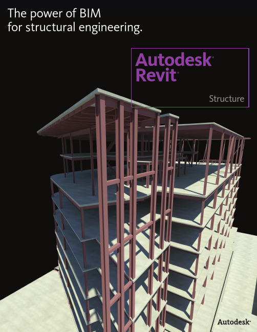
Autodesk Revit Structure软件使用说明书
for structural engineering.Autodesk®Revit®StructureImprove Efficiency, Accuracy, and Coordination Autodesk ® Revit ® Structure software improves the way structural engineers and drafters work. Revit Structure helps minimize repetitive modeling and drawing tasks as well as errors due to manual coordination between structural engineers,architects, and drafters. The software helps reduce time spent producing final construction drawings and helps increase the accuracy of documentation, improving overall project deliverables for clients.Smoother CoordinationBecause Autodesk Revit Structure uses building information modeling (BIM), every view, drawing sheet, and schedule represents the same underlying database. As project team members work on the same project, making inevitable and necessary changes to the building structure, parametric change technology in Autodesk Revit Structure automatically coordinates changes across all other representations of the project—model views, drawing sheets, schedules, sections, plans, and details. The design and documentation stay coordinated, consistent, and complete.Bidirectional AssociativityThe building model and all of its views are part of the same information system. This means changes to any part of the structure need to be made only once, maintaining consistency throughout the documentation set. For example, if the sheet scale changes, the software automatically resizes annotations and graphics. If a structural member changes, any views that include the element are coordinated and updated automatically, including name tags and other labels referring to the element properties.Concurrent modeling for structural design, analysis, andcoordinated documentationCollaboration with ArchitectsEngineers working with architects using Autodesk ® Revit ® Architecture software can experience the advantages of BIM and share the same underlying building database. Creation of the structural model is faster with integrated Autodesk Revit platform tools. With interference checking between structural and architectural objects, engineers can more quickly detect coordination problems before sending drawings to the construction site.Collaboration with Mechanical, Electrical, and Plumbing EngineersStructural engineers working with mechanical, electrical, or plumbing engineers using AutoCAD ® MEP software can improve design coordination. Autodesk Revit Structure users can export their structural model into AutoCAD MEP, where the MEP engineer can perform clash detection between pipes and structural elements. Autodesk Revit Structure can also import 3D duct and pipe objects from AutoCAD MEP into the structural model via ACIS ® solids to help detect interferences visually. In addition, structural engineers who are working with MEP engineers using Autodesk ® Revit ® MEP software can take better advantage of building information modeling.Whether engineers are designing steel, cast-in-place concrete, precast concrete, masonry, or wood structures, standard modeling objects in Autodesk Revit Structure software include walls, beam systems, columns, slabs, and foundations. Additional structural objects can be created as parametric components.Parametric ComponentsUsing Autodesk Revit Structure, engineers can create many types of structural components, such as joist systems, beams, open web joists, trusses, and intelligent wall families. No programminglanguage is required to use parametric components, also known as families . The family editor contains all the data to graphically represent an element in 2D and 3D at various levels of detail.Multiuser CollaborationAutodesk Revit Structure enables multiple team members on the same network to work together on a model, while their work stays fully coordinated. A wide range of collaboration modes provides more flexibility to better meet the project team’s workflow—from on-the-fly, simultaneous access to the shared model to formal division of the project into discrete shared units or individually managed linked models.Design OptionsWith Autodesk Revit Structure, engineers can stay focused on structural engineering. The software enables users to explore design changes, develop and study several design alternatives to make key design decisions, and more easily present multiple schematic designs to clients. Each option can be substituted into the model for visualization and quantity takeoff to help team members and clients make more informed decisions.Leading Analysis and Design Integration Analytical models created with Autodesk Revit Structure contain information such as loads, load combinations, member sizes, and release conditions. The analytical model can be the entire building model, one wing of the building, or even a single structural frame. Engineers use selection filters with structural boundary conditions to send substructures (such as a frame, floor, or wing of the building) to their analysis software without the need to send the entire model.The creation of the analytical model usesengineering rules to produce a consistent analytical representation of the physical structure. Engineers can override initial analytical settings and edit the analytical model before linking to structural analysis packages.Enhance Structural Modeling and Analysis Capabilities Autodesk Revit Structure can inspire structural engineers to greater engineering insight: user-defined rules help the analytical models adjust their location to the analytical projection planes of attached or adjacent structural elements. Engineers can automatically check analytical inconsistencies such as missing supports, global instabilities, or framing anomalies before sending the model to structural analysis.The analysis programs then return the design information and dynamically update the physical model and documentation, minimizing manyredundant, repetitive tasks such as modeling frames and shells in a variety of different applications. Autodesk Revit Structure integrates with Autodesk ® Robot™ Structural Analysis Professional software as well as other widely used analysis and design applications. To find out which software partners have linked their applications to Autodesk Revit Structure through the Autodesk ® Revit ® platform API (application programming interface), visit /revitstructure.Help save time by creating physical and analyticalstructural models in a single application.Deliver Comprehensive Construction Documents Material-specific tools help construction documents conform to industry and office standards.For steel, features such as beam coping and automatic symbolic cutbacks as well as an extensive library of detail components, are available.For concrete structures, display options provide control over the visibility of the concrete elements. Reinforcement bars are also available for concrete elements, including columns, beams, walls, and foundations.Automatic Sections and ElevationsCreating sections and elevations in Autodesk Revit Structure is more simple compared to traditional methods. Because views are just a differentrepresentation of the entire building model, users get cuts faster throughout a structure. Use them at any time to work in the most appropriate view. When the construction documents are ready to print, section tags and elevation symbols of the views that are not placed onto any drawing sheet are automatically hidden.Automatic Drawing Sheet ReferencesThis functionality helps safeguard that no section, elevation, or callout references the wrong drawing or sheet and that all data and graphics, details, schedules, drawings, and sheets in the drawing set are current and coordinated.DetailsAutodesk Revit Structure allows callouts for typical details and for specific ones. Entire sheets of typical details can be created from scratch in Autodesk Revit Structure using its traditional 2D drafting tools.Designers can also import DWG details from AutoCAD ® software and link them into Autodesk Revit Structure, using the project browser to manage them.Specific details come directly from the views of the model. These model-based details are completed with 2D parametric components (metal deck, concrete masonry unit, anchor bolts in footings, fasteners, welded symbols, steel connection plates, concrete rebar, and more) and annotations such as text and dimensions.When the geometry gets complicated, Autodesk Revit Structure offers 3D model-based details such as 3D representation of building expansion joints, steel connections, rebar in concrete elements, and more.SchedulesHelp save time by creating schedules on demand, and update the model and views automatically simply by making a change in a schedule. Schedule features include sorting, filtering, grouping, and counting as well as user-defined formulas.Engineers and project managers can use customized schedules to check the overall structural design. For example, they can schedule and review structural loads before integrating the model with analysis software. If the load value needs to be changed, it can be modified in the schedule and automaticallycoordinated throughout the model.Use a comprehensive set of dedicated tools to deliver structural drawings and help reduce errors due to manualcoordination of design changes.Building Information Modeling for Structural Engineering BIM for structural engineers follows this same methodology for the entire structural engineering process, focusing on a digital model that can be used for coordination with architects; mechanical, electrical, and plumbing engineers; and civilengineers that is integrated with analysis, design, and construction documentation, and extending that digital model from design through fabrication and construction.Autodesk Revit StructureAutodesk ® Revit ® Structure software is thebuilding information modeling (BIM) solution for structural engineers, providing purpose-built tools for structural design, analysis and documentation. Make better decisions, earlier in the design process by more accurately visualizing and analyzing structures, before they are built.Building information modeling (BIM) is anintegrated process built on coordinated, reliable information about a project from design through construction and into operations. By adopting BIM, architects, engineers, contractors, andowners can more easily create coordinated, digital design information and documentation; use that information to visualize, simulate, and analyze performance, appearance, and cost; and reliably deliver the project faster, more economically, and with reduced environmental impact.Make better decisions, earlier in the design process by more accurately visualizing and analyzing structures, beforethey are built.。
Autodesk Revit Architecture 用户指南说明书
AUTODESK REVIT ARCHITECTURE FOR AUTOCADUSERSWHITE PAPERAutodesk Revit Architecture forAutoCAD UsersAutodesk Revit Architecture building design software works the way architects and designers think, so you can develop higher-quality, more accurate architectural designs. Built for Building Information Modeling (BIM), Autodesk Revit Architecture helps you capture and analyze concepts and maintain your vision through design, documentation, and construction. Make more informed decisions with information-rich models to support sustainable design, construction planning, and fabrication. Automatic updates keep your designs and documentation coordinated and more reliable.Many building industry professionals are familiar with AutoCAD®software and use it today for their work. This white paper will help those who are familiar with that tool understand how Autodesk Revit Architecture works on their terms, introducing some of the main features and concepts in Autodesk Revit Architecture and comparing them to those you may be familiar with in AutoCAD.If you are a current AutoCAD user interested in Autodesk Revit Architecture and building information modeling, the AutoCAD Revit Architecture Suite software may be right for you. It couples the industry-leading AutoCAD, AutoCAD Architecture software with the state-of-the-art Autodesk Revit Architecture software for building information modeling into a single, comprehensive solution. Autodesk Revit Architecture Suite software turns maximum flexibility into competitive advantage. It enables you to make the switch to Building Information Modeling (BIM) at your own pace, while continuing to support existing software, training, and design data investments.True 3D designA major difference between Autodesk Revit Architecture and AutoCAD is that you work with intelligent objects rather than lines and curves. This is a tremendous productivity gain because—unlike traditional drafting with AutoCAD, which requires a wall to be drawn several times, once for floor plan, once for elevation, and then again in section—we only have to model the wall once within Autodesk Revit Architecture, and at any given time, you can display this information as floor plans, sections, schedules, and perspectives, just to name a few.An even greater advantage with Autodesk Revit Architecture is that you are creating a parametric Building Information Model; if you make a change anywhere, it will automatically update all dependencies. With lines and curves, each view remains a separate drawing, so edits need to be repeated for each drawing type, which is a very manual process and could lead to greater risk of error.Autodesk Revit Parametric ComponentsAutodesk Revit Architecture is a true parametric architectural building modeler. The modeling enginein AutoCAD contains primitive 3D objects and requires that all custom shapes be created manually. Autodesk Revit Architecture contains 3D parametric building elements. Autodesk Revit Parametric Components are an open, graphical system for design thinking and form making, a powerful way of expressing design intent at increasingly detailed levels. Parametric Components can be used to generate the most elaborate assemblies—including intricate iterative, algorithmic, and behavioral characteristics—as well as the most elementary building parts. No programming language or coding is required to drive this powerful system. And any and all relationships are available to be expressed directly in the system; nothing is assumed.Revit Parametric Components carry information about their relationships to other objects in the building, unlike the blocks and solids used in AutoCAD. For example, in Autodesk Revit Architecture, a wall’s properties can be defined as rising to the next level or roof. After you set this property, Autodesk Revit Architecture ensures that your wall will retain its relationship to the next level or roof no matter what changes you make in the building.AUTODESK REVIT ARCHITECTURE FOR AUTOCADUSERSDimensions always correspond to the actual size of the building elements. Updating a dimension automatically updates the parametric components and their relationships to other components. Schedules provide another view of the comprehensive Autodesk Revit Architecture model. Changes to a schedule view are automatically reflected in all other views.Families vs. BlocksAutoCAD users are accustomed to storing symbols as blocks in individual DWG files. Autodesk Revit Architecture stores similar parametric components in family files. One of the strengths of component families is that they can be controlled by parameters, which allow for a great deal of flexibility. For example, a table family can be created to have several sizes, all based on parameters that can be set by the user, allowing for a single family definition to accommodate several different kinds of tables. Parameters can control more than just sizes—they can control materials, visibility states, and non-graphical information (cost, URL, etc.)Alignment vs. OsnapsAutodesk Revit Architecture offers tools like Temporary Dimensions and Alignment Guides. Alignment guides are similar to the Object Tracking feature in AutoCAD. Temporary lines and arc extensions, as well as other useful snap points relative to your current position in the model, are an advantage within Autodesk Revit Architecture. This is in contrast to the osnap feature of AutoCAD, which snaps to any entity that fits the current osnap settings. With Autodesk Revit Architecture, you do not need to change the UCS in order to place blocks or creating your drawings; you can quickly place doors, windows and other components correctly with the appropriate placement and orientation options. Doors open in the desired direction and windows are placed with the correct sill height on the wall. You can place these components in either 2D or 3D views, whichever is easiest.One Model, Many ViewsAutodesk Revit Architecture makes extensive use of various views since all model information is stored in a single, coordinated database. Autodesk Revit Architecture can generate schedule, drawing sheet, 2D view, and 3D view at any given time. Many views may be opened at the same time and any changes made in one view are automatically updated in all other views. Plan, section, and 3D view can be opened side by side so you can verify that moving or deleting a component in one view will automatically coordinate the changes in section and 3D view as well. This feature, which means that a change anywhere is a change everywhere, is extremely valuable for experimenting with design changes.No Command Line or La y e rsWhen working in Revit, AutoCAD users will notice the absence of the command line and layer control. The Autodesk Revit Architecture user interface offers desktop organization through a large drawing window with access to the tools and commands you need. Tools are organized into a collection of tabs and panels to represent architectural workflows such as Annotation or Collaboration. With Revit, designers can stay more focused on the model rather than the keyboard and command line.Layers are not needed to control the visibility of elements within Autodesk Revit Architecture. Visibility is controlled through the Visibility/Graphics dialog. For example, when you model a wall, the wall automatically belongs to Wall category with certain predefined line types, and line weight. The Visibility/Graphics dialog works on a per-view basis, comparable to the AutoCAD Freeze/Thaw/On/Off by viewpoint feature.Single File, Multi-user ProjectsAutoCAD users are accustomed to storing and retrieving project data from multiple files. In Autodesk Revit Architecture, all project data is stored in the single database. This creates a more collaborative environment between users because everyone is working on the same model simultaneously, which means everyone working on the model must coordinate and maintain constant communication with one another. Every time someone saves their work, the changes are incorporated and update in the central file.AUTODESK REVIT ARCHITECTURE FOR AUTOCADUSERSImport/Export DWGAutodesk Revit Architecture provides industry-leading DWG compatibility. It supports exporting to DWG and DXF, SAT, and DGN file format. When exporting, Autodesk Revit Architecture matches its components and their subcategories from the current view to either industry standard or user-defined layer names. If you use one of the export tools while in a 3D view, Autodesk Revit Architecture exports the actual 3D model, not a 2D representation of the model; similarly, if you export while in 2D view, it will export a 2D view. This allows for smooth coordination and exchange of information among project team members.Producing Paper DrawingsBecause drawings are the critical output of the design process, the parametric change technology in Autodesk Revit Architecture enables fast and accurate plotting. With Autodesk Revit Architecture, all drawings are produced from the same, single parametric building model used to create the design. Any changes to your design along the way are always updated in your drawing sheet views. Changes to elevations, sections, and callouts are immediately updated in all reflected views. Any view you have created of the model can be added to a sheet and properly scaled.Once placed on the sheet, Autodesk Revit Architecture can enable the designer to perform any last minute placements just as easily in a sheet view as in a model view. Scale-dependent line-weight and scale-independent annotation size allow reuse of information in views without complex reformatting, which greatly reduces management overhead. The WYSIWYG display also lets the user see the final result before output for fewer plotting errors. Finally, the plotter hardware support in Autodesk Revit Architecture is only limited by the operating system. If there is a Microsoft® Windows® driver for your plotter, Autodesk Revit Architecture can use it.Thank you for your interest in Autodesk Revit Architecture. Autodesk Revit Architecture will help you design and document your building projects more productively, with better coordination, and with better quality. If you have any further questions about Autodesk Revit Architecture or would like to know more please visit us online at /revit-architecture.Autodesk, AutoCAD, ATC, Buzzsaw, Design Web Format, DWF, DXF, ObjectDBX,and Revit are either registered trademarks or trademarks of Autodesk, Inc., in theUSA and other countries. Flexlm is a registered trademark of GLOBEtrotterSoftware, Inc., a Macrovision Company. All other brand names, product names, ortrademarks belong to their respective holders. Autodesk reserves the right to alterproduct offerings and specifications at any time without notice, and is notresponsible for typographical or graphical errors that may appear in this document.Occasionally, Autodesk makes statements regarding planned or future developmentefforts for our existing or new products and services. These statements are notintended to be a promise or guarantee of future delivery of products, services, orfeatures but merely reflect our current plans, which may change. The Companyassumes no obligation to update these forward-looking statements to reflect anychange in circumstances, after the statements are made.© 2005, 2011 Autodesk, Inc. All rights reserved.。
在“建筑结构”课程教学中引入Revit软件
在“建筑结构”课程教学中引入Revit软件摘要:建筑结构是土木工程专业一门非常重要的课程,但其知识体系的复杂性、抽象性和实践性给教学带来了一定难度。
为了解决这一难题,在教学中引入了Revit软件,借此软件可以实现对建筑结构整体或单体构件的外观形态与内部结构及钢筋布置进行系统展示,对真实结构进行仿真模拟。
应用结果证明,该工具不仅有助于建筑结构课程教学水平的提高,而且可以使学生在准确掌握建筑结构专业知识的同时,激发学生对专业课程的学习兴趣。
关键词:Revit软件;建筑结构;课程教学;仿真模拟:0引言建筑结构是土木工程专业基础必修课程之一。
然而由于该课程的知识体系的复杂性、抽象性和实践性,使得传统的授课方式-黑板板书和口头讲解已经不能让学生将相关知识掌握透彻。
因此,如何有效解决建筑结构课程教学的这一问题,已成为建筑结构课程教学中的一个重要问题。
1建筑结构课程的教学现状建筑结构是一门理论与实践结合的专业课程,也是一门集材料、设备、工艺、方法和管理为一体的综合性应用技术。
该课程应用范围较广,基础性较强,是土木工程专业十分重要的课程之一,也为本专业其他课程的学习奠定了重要的基础。
但与土木工程专业的其他课程相比,该课程具有较强的专业知识综合性和复杂性,知识体系具有显著的系统性和抽象性。
特别是对于一些砌体结构和钢筋混凝土结构中构件的构造设计,这些需要靠实际工程经验积累的,就需要学生具有一定的工程实践经验与体会,因此,这就给学生在建筑结构课程中的学习带来了一定的难度。
但更主要的是,在实际教学中,老师的授课方式多采用PPT幻灯片放映加上黑板板书和口头讲解,而对于实际工程中的一些结构形式,大多数老师会选择在PPT中加入相应的图片、视频或者使用CAD软件帮助学生理解学习。
然而图片、视频和CAD绘制的图形更多的是二维展示,而在对结构构件的受力整体状况、结构体系、不同结构类型的划分等等三维状态做解释的时候,由于学生接收能力的参差不齐,学生在脑海中无法呈现一个立体画面并有效理解建筑结构的内外形式和受力状态。
基于Revit软件《建筑识图与构造》在课程教学中的重构运用

基于Revit软件《建筑识图与构造》在课程教学中的重构运用摘要:结合《建筑识图与构造》课程在实施过程中的抽象难懂的问题,针对问题出现的原因进行深入分析,依托Revit软件目前的教学方法存在的问题进行尝试运用,以某别墅建筑平面施工图识读与绘制的教学为例,将可视化、动态化的Revit三维模型项目文件融入到课前、课中和课后的教学实际中,解决前期出现的问题,优化课程教学,进而提高学生的识图运用能力,为后续课程的学习打下坚实基础。
关键字:Revit,建筑识图与构造、课程教学Revit是美国Autodesk公司基于CAD基础开发的一套系列软件的名称。
Revit系列软件主要应用于于建筑工程建筑信息模型(BIM)的构建,帮助建筑设计师在建筑设计、建造和维护质量方面更好、更有效的服务于建筑全寿命周期的各项工作。
Revit可以简单地理解为:将传统的二维图像信息,通过 BIM技术平台集中多方多维度的多元化信息,进行相应的加工、处理和整合,建立的一种多维度模型[1]。
由于Revit软件可导出建筑构、配件的三维设计尺寸和体积数据,并能对相关构件的性能进行赋值,在建筑平面图、立面图的基础上制作或演示建模可以更为直观的展现建筑形态,本文结合教学实践应用,对Revit软件在《建筑识图与构造》中应用作简要的分析运用。
1前言《建筑识图与构造》开设的主要目的是研究建(构)筑物的基本构造及其基本原理,能够准确识读常见的施工图纸,并能准确运用于实际的一门应用型课程,是一门重要的基础专业课程。
因此课程教学效果的好坏将影响学生识图、绘图的能力,进而影响学生后续专业课程的学习,甚至影响到学生毕业后能否成为合格的技能人才。
目前《建筑识图与构造》课程的直观性和实践性强已成共识,传统的板书、PPT演示、实际工程项目图纸抄绘、工法楼等普遍运用于教学实际。
然而采用传统板书、PPT 演示的教学方法稍显枯燥,学生学习兴趣不高,教学效果与预期存在较大差异;采用实际工程项目图纸抄绘的教学方法有一定逻辑系统性且有项目任务驱动,能有效的提高学生的积极性,但常规图纸均为二维图纸展示,学生要将二维的平面图、立面图和剖面图关联三维形态较困难,抽象且难以理解。
- 1、下载文档前请自行甄别文档内容的完整性,平台不提供额外的编辑、内容补充、找答案等附加服务。
- 2、"仅部分预览"的文档,不可在线预览部分如存在完整性等问题,可反馈申请退款(可完整预览的文档不适用该条件!)。
- 3、如文档侵犯您的权益,请联系客服反馈,我们会尽快为您处理(人工客服工作时间:9:00-18:30)。
Autodesk Revit Architecture软件在教学中的运用作者:何罗平来源:《教师博览·科研版》2016年第02期[摘 ; 要] Revit系列软件是我国建筑业BIM体系中使用最广泛的软件之一。
它能帮助建筑设计师设计、建造及维护建筑。
教师在“建筑识图”课程教学中,应积极运用Autodesk Revit Architecture软件制作或演示建模,使学生加深对建筑构、配件作用及材料的认识,帮助学生掌握识图技巧,以提高建筑识图课程的教学效果。
[关键词] Autodesk Revit Architecture;建筑识图;教学BIM技术始于20世纪末的美国,近年来发展迅速,在欧洲及日本等地区得到了广泛的应用,国内一些工程项目也开始应用BIM技术。
随着应用范围的日益扩大,BIM技术得到了政府部门的高度重视,住房城乡建设部印发的《关于推进建筑信息模型应用的指导意见》中明确提出BIM在工程领域应用的重要意义。
Revit系列软件是专为建筑信息模型(BIM)构建的,是实现BIM技术的运用软件。
其中Autodesk Revit Architecture可导出建筑构、配件的三维设计尺寸和体积数据,并且在建筑平面图、立面图的基础上制作或演示建模。
软件的联动功能具有一处修改、处处更新等优势,是其他软件无可比拟的。
Autodesk Revit Architecture软件不仅为工程师、承包商与业主搭建了沟通协作的平台,同时为教师讲授“建筑识图”课程提供了高效、便捷的条件。
一、建筑识图课程的教学现状以往的建筑识图课程讲授,主要依靠板书、电子PPT教案等教学方式将建筑识图知识灌输给学生。
由于建筑识图与建筑构造知识联系紧密,知识理论性较强,导致出现教师辛苦讲授,学生却往往难以理解的尴尬境地。
“建筑识图”这门课所面对的学生往往是一年级新生,他们对建筑形体和相关知识毫无概念。
学生采用正投影绘制工程图时,形状复杂的建筑形体对他们的空间想象能力有着较高的要求,仅仅依靠图片和CAD文件是难以取得理想的教学效果的。
只有使学生对建筑形体获得直观感受,且在细心观察形体的情况下,才能获得初步印象。
在学习建筑构造知识部分,由于该课程具有理论性强、直观性差、知识点难以理解等特点,学生只能通过凭空想象和死记硬背来接受教学内容,导致对概念的理解不深,一知半解的现象居多,容易给学生带来挫败感。
二、Autodesk Revit Architecture软件在课程教学中的作用通过对教学中所遇问题的分析以及对Autodesk Revit Architecture软件的深入研究,发现它强大的功能可以帮助教师快速创建几何模型,并可对几何模型随时进行编辑。
利用其三维视图和实时阴影展示几何模型效果,增加了学生学习过程中的趣味,是一种培养学生空间想象能力的重要方式。
Autodesk Revit Architecture软件可以将传统的2D图纸转化为3D房屋模型,并随时将视图切换到平面图、立面图、剖视图进行观察,对复杂建筑构、配件进行视图放大、剖切。
此外,它能自动生成构件数量、材料用量、门窗表、材料用量表等。
借助Autodesk Revit Architecture 软件,教师可以深入阐述建筑构、配件的作用及设计要求,学生可对建筑构、配件进行详细观察和深入理解,不仅快速提升了学生识读工程图的能力,而且加深了学生对建筑的理解。
多年以来,建筑类院校教师基本上采用Auto CAD软件进行“建筑识图”课程教学。
Auto CAD软件具有强大的平面表现功能,但它并不是只针对建筑行业开发,缺乏相应的建筑专业制图标准。
学生在绘图过程中使用Auto CAD软件,缺乏即时直观的三维效果,对建筑平面图、立面图、剖面图未进行关联修改,导致产生图纸内容之间不一致的低级错误,不利于培养学生全局把握建筑绘图及设计的能力。
而Autodesk Revit Architecture的强大功能恰好弥补了Auto CAD软件的诸多缺陷。
近些年,越来越多的建筑类院校开始参与Autodesk Revit Architecture软件教学与研究,该软件已成为学生学习“建筑识图”“建筑设计”“节能建筑设计”等课程教学必备的计算机辅助软件。
三、运用Autodesk Revit Architecture软件开展教学的切入点针对上述Autodesk Revit Architecture软件在“建筑识图”教学中的作用,教师可以从以下方面入手,运用Autodesk Revit Architecture开展教学。
(一)利用Autodesk Revit Architecture制作课件Autodesk Revit Architecture强大的文件格式兼容功能,给教师制作教学课件带来便利。
它所兼容的格式涵盖CAD格式、图像格式、ODBC、HTML、TXT、MDB、XLS等,教师可根据教学需要,把编辑完成的Autodesk Revit Architecture图形内容输出在上述任意一种文件格式中使用。
(二)利用Autodesk Revit Architecture展示模型以往在学习工程图内容时,教师利用实物模型展示其形状,利用板演分析其制图过程。
学生由于受视觉条件所限,难以准确观察形体特征,另一方面教师板演过程也会降低教学效率。
利用Autodesk Revit Architectur。
3D视图中viewcube操控命令,可以将编辑完成的建筑模型根据观察需要把视图切换至轴测、正投影等特定视角,也可以利用导览工具列将模型进行全方位展示。
学生可以多角度观察模型,通过3D直观效果自主分析形体特征。
(三)利用Autodesk Revit Architecture建模基于Autodesk Revit Architecture软件的强大功能,教师应在教学实施中不断挖掘该软件服务于课程教学的潜在价值。
该软件极具亲和力的工程语言,为教师提供了内容丰富的教学资源和高效快捷的教学手段,其建立的三维信息化模型符合学生直观、具体、清晰的认知规律。
三维信息模型比起虚拟二维图形直观程度更高,但对学生现有识图的能力要求却不高,有利于帮助学生快速理解建筑图样,激发他们学习该课程的热情,增强学习过程中的趣味体验,同时培养其观察问题、分析问题的能力。
教师在教授房屋工程图时,可以利用一套完整的建筑工程图(DWG格式)导入Autodesk Revit Architecture。
在CAD文档基础上建模,把建模过程贯穿于教学过程。
建模过程会涉及参考平面及网格、基础元件、楼层元件、墙元件、门窗元件、楼梯元件、围栏元件、屋顶元件等,且每个元件都可编辑相应的材质。
Autodesk Revit Architecture材质浏览器能展示材质实际效果,例如混凝土、木材和玻璃等,使对象具有真实的外观和行为。
通过3D视图与正投影视图相互切换,不仅可以帮助学生加深对建筑构、配件作用及材料的认识,而且可以帮助学生掌握识图技巧。
教师也可利用在三维视图属性里的剖面框,通过拉动剖面框完成建筑模型的剖视效果。
学生在剖视效果中能直观感受模型内部结构,避免在学习剖面时只能靠想象的情况,同时降低了教师讲解建筑剖面图的难度。
Autodesk Revit Architecture中的所有构件都基于族。
术语“族”是一种非常先进的概念,可以帮助教师管理数据和进行变更。
Autodesk Revit Architecture库中包含数千种族,每个族文件可生成多种建筑构、配件。
教师可以在公开网站上获得族文件中常有数种尺寸或类型的构、配件,也可根据教学内容需要在新建族中创建独立图元,并将创建的图元载入到模型中使用。
“族”的使用不仅大大丰富了教学资源,而且补充了教学内容。
结合利用Autodesk Revit Architecture和Autodesk Inventor软件中的功能,可以实现数字化的“设计—建造”工作流程,更为忠实地传达教师的教学意图,使学生全面掌握建筑构、配件设计到施工的过程。
通过数字样机和建筑信息模型,使学生以数字方式提前体验设计创意,了解仿真建筑性能和施工可行性,传达并诠释建筑设计意图,从而提高学生对建筑设计及施工完整流程的认识。
教师可利用Autodesk Revit Architecture演示建模完成的最终效果。
在Autodesk Revit Architecture三维视图中创建相机,设定相应参数后,通过鼠标移动至首层平面图区,单击鼠标生成三维透视图。
另外,教师也可在创建相机后,点击视图栏中渲染按钮,待设定相应参数后,将建筑模型渲染效果展示给学生,学生将通过最终效果体会建筑方案。
建筑方案日照分析决定了建筑物采光条件的好坏,教师可在日光设定选项中先调整数据及日照路径,然后输出日照动画格式,最后在视频播放器中演示动画效果。
学生不仅能识读图纸,而且在熟读图纸的基础上了解到影响建筑方案的因素,为学习“建筑设计”课程建立初步概念。
教师可利用Autodesk Revit Architecture创建图纸详图,将详图导入图纸视图中进行布图,最后在导出设置选项中导出Auto CAD格式。
在操作过程中,学生在该软件强大的可视化功能帮助下,系统掌握房屋外墙、楼梯、阳台、屋顶等构件详图内容及表达方式,有效解决了学生学习详图的难点。
随着《关于推进建筑信息模型应用的指导意见》的贯彻落实,我国建筑领域将进一步掀起BIM应用的热潮。
BIM技术不仅推动我国建筑业的转型升级和健康持续发展,而且为支撑建筑行业技术升级、变革生产方式、创新管理模式奠定了坚实的基础。
目前,运用Autodesk Revit Architecture软件教学的尝试刚刚开始。
各大建筑类院校应意识到自身在培养Revit系列人才任务中所担当的角色,重视相关设备建设,将Revit系列课程纳入学校课程体系,以提升工程类相关课程教学竞争力。
对于教师而言,应积极运用该系列软件服务于课程教学,培养掌握Revit系列技术的后备人才。
参考文献[1]董蓓.基于建筑信息模型的信息管理技术[J].智能建筑,2014,(9).[2]张萌.探索增加《建筑构造模型认识及制作》.课程在教学中的作用[J].城市建设理论研究(电子版),2013,(16).[3]梁炳堃,罗远峰.系统科学方法在BIM中的应用研究[J].广州建筑,2014,(5).责任编辑 ; 张淑光。
