SYS-EXP8中文资料
HCS08系列微控制器参考手册(中文)

HCS08系列微控制器参考手册第一册苏州大学飞思卡尔嵌入式系统研发中心翻译 2009年11月目录第一章通用信息与结构框图 (1)1.1HCS08系列微控制器介绍 (1)1.2HCS08CPU编程模型 (2)1.3外设模块 (2)1.4MC9S08GB60的特点 (3)1.4.1 HCS08系列的共性 (3)1.4.2 MC9S08GB60的特点 (3)1.5MC9S08GB60的结构框图 (4)第二章引脚及其连接 (5)2.1简介 (5)2.2推荐的系统连接 (5)2.2.1 电源 (7)2.2.2 MC9S08GB60振荡器 (7)2.2.3 复位 (8)2.2.4 背景/模式选择(BKGD/MS) (8)2.2.5 通用I/O及外设端口 (8)第三章工作模式 (10)3.1简介 (10)3.2特征 (10)3.3运行模式 (10)3.4背景调试模式 (11)3.5等待模式 (12)3.6停止模式 (12)3.6.1 Stop1模式 (13)3.6.2 Stop2模式 (13)3.6.3 Stop3模式 (14)3.6.4 停止模式下激活BDM使能 (14)3.6.5 设置OSCSTEN位 (15)3.6.6 停止模式下LVD使能 (15)3.6.7 停止模式下的片上外设模块 (15)3.6.8 系统选择寄存器(SOPT) (17)3.6.9 系统电源管理状态和控制寄存器1(SPMSC1) (18)3.6.10 系统电源管理状态和控制寄存器2(SPMSC2) (19)第四章片上存储器 (21)4.1简介 (21)4.2HCS08核定义的存储器组织 (21)4.2.1 HCS08存储器组织 (21)4.2.2 MC9S08GB60存储映像 (22)4.2.3 复位和中断向量表 (23)4.3寄存器地址和位分配 (24)4.4RAM (29)4.560K字节的FLASH (29)4.5.1 特征 (30)4.5.2 写入、擦除和空白检测命令 (30)4.5.3 命令时间和突发模式写入 (32)4.5.3.1 行和FLASH的组织结构 (32)4.5.3.2 程序命令时序 (33)4.5.4 访问错误 (34)4.5.5 向量重定向 (34)4.5.6 FLASH块保护(MC9S08GB60) (34)4.6MC9S08GB60的安全性 (35)4.7MC9S08GB60的FLASH寄存器和控制位 (36)4.7.1 FLASH时钟分频寄存器(FCDIV) (36)4.7.2 FLASH选项寄存器(FOPT和NVOPT) (37)4.7.3 FLASH配置寄存器(FCNFG) (38)4.7.4 FLASH保护寄存器(FPROT和NVPROT) (38)4.7.5 FLASH状态寄存器(FSTAT) (39)4.7.6 FLASH命令寄存器(FCMD) (40)4.8FLASH存储器应用实例 (41)4.8.1 FLASH模块时钟的初始化 (41)4.8.2 擦除FLASH的一页(512字节) (42)4.8.3 DoOnStack子程序 (43)4.8.4 SpSub子程序 (45)4.8.5 FLASH的字节编程 (46)第五章复位和中断 (47)5.1简介 (47)5.2MC9S08GB60复位和中断的特征 (47)5.4计算机正常操作监控模块(COP)看门狗 (48)5.5中断 (48)5.5.1 中断堆栈结构 (49)5.5.2 外部中断请求(IRQ)引脚 (50)5.5.2.1 引脚配置选项 (50)5.5.2.2 边沿/电平触发 (50)5.5.3 中断向量、中断源和局部屏蔽 (51)5.6低电压检测系统(LVD) (52)5.6.1 上电复位操作 (52)5.6.2 LVD复位操作 (52)5.6.3 LVD中断操作 (53)5.6.4 低电压警告(LVW) (53)5.7实时中断(RTI) (53)5.8复位、中断以及系统控制寄存器和控制位 (53)5.8.1 中断请求状态和控制寄存器(IRQSC) (54)5.8.2 系统复位状态寄存器(SRS) (55)5.8.3 系统背景调试强制复位寄存器(SBDFR) (56)5.8.4 系统选项寄存器(SOPT) (56)5.8.5 系统设备识别寄存器(SDIDH、SDIDL) (57)5.8.6 系统实时中断状态和控制寄存器(SRTISC) (57)5.8.7 系统电源管理状态控制寄存器1(SPMSC1) (58)5.8.8 系统电源管理状态和控制寄存器2(SPMSC2) (59)第六章中央处理单元 (61)6.1简介 (61)6.2编程结构和CPU寄存器 (61)6.2.1 累加器(A) (62)6.2.2 变址寄存器(H:X) (63)6.2.3 堆栈指针(SP) (64)6.2.4 程序计数器(PC) (66)6.2.5 条件码寄存器(CCR) (66)6.3寻址方式 (70)6.3.1 隐含寻址方式(INH) (71)6.3.2 相对寻址方式(REL) (71)6.3.3 立即寻址方式(IMM) (72)6.3.4 直接寻址方式(DIR) (72)6.3.5 扩展寻址方式(EXT) (72)6.3.6.1 无偏移量变址方式(IX) (73)6.3.6.2 无偏移量变址、变址加1寻址方式(IX+) (73)6.3.6.3 8位偏移量变址方式(IX1) (73)6.3.6.4 8位偏移量变址、变址加1寻址方式(IX1+) (73)6.3.6.5 16位偏移量变址方式(IX2) (73)6.3.6.6 8位偏移量堆栈寻址方式(SP1) (74)6.3.6.7 16位偏移量堆栈寻址方式(SP2) (74)6.4特殊操作 (75)6.4.1 复位序列 (75)6.4.2 中断 (76)6.4.3 等待模式 (76)6.4.4 停止模式 (76)6.4.5 背景模式 (77)6.4.6 总线周期的用户观点 (77)6.5通过指令类别进行指令集描述 (78)6.5.1 数据传送指令 (78)6.5.1.1 加载与存储 (78)6.5.1.2 位的置位与清零 (81)6.5.1.3 存储器到存储器的传送 (82)6.5.1.4 寄存器传输和半字节交换 (82)6.5.2 算术运算指令 (83)6.5.2.1 加、减、乘和除指令 (83)6.5.2.2 加一、减一、清零和求补 (88)6.5.2.3 比较和测试 (88)6.5.2.4 BCD的计算 (88)6.5.3 逻辑操作指令 (89)6.5.3.1 与、或、异或与求补 (90)6.5.3.2 位测试指令 (91)6.5.4 移位类指令 (91)6.5.5 跳转、转移和循环控制指令 (93)6.5.5.1 无条件跳转和转移指令 (94)6.5.5.2 简单转移 (95)6.5.5.3 有符号转移 (95)6.5.5.4 无符号转移 (95)6.5.5.5 位条件转移 (96)6.5.5.6 循环控制 (96)6.5.6 相关堆栈指令 (97)6.6指令简表 (102)6.7汇编语言指南 (114)6.7.1 列表行 (115)6.7.2 汇编指令 (116)6.7.2.1 BASE——设定编译器的缺省数进制 (116)6.7.2.2 INCLUDE——指定附加源文件 (116)6.7.2.3 NOLIST/LIST——关闭或打开程序列表 (116)6.7.2.4 ORG——设置程序的起始位置 (117)6.7.2.5 EQU——把一个标号和一个数值相关联 (118)6.7.2.6 dc.b——定义存储器中字节化常量 (119)6.7.2.7 dc.w——在存储器中定义16位(字)常量 (119)6.7.2.8 ds.b——定义存储(保留)内存变量字节 (120)6.7.3 标号 (121)6.7.4 表达式 (122)6.7.5 通用文件协议 (123)6.7.6 目标代码(S19)文件 (125)第七章开发支持 (129)7.1介绍 (129)7.2特点 (130)7.3背景调试控制器(BDC) (130)7.3.1 BKGD引脚描述 (131)7.3.2 通信细节 (132)7.3.2.1 BDC通信速率考虑事项 (132)7.3.2.2 位时序细节 (133)7.3.3 BDC寄存器和控制位 (135)7.3.3.1 BDC状态和控制寄存器 (135)7.3.3.2 BDC断点匹配寄存器 (137)7.3.4 BDC命令 (137)7.3.4.1 SYNC——要求时序参考脉冲 (138)7.3.4.2 ACK_ENABLE (139)7.3.4.3 ACK_DISABLE (139)7.3.4.4 BACKGROUND (139)7.3.4.5 READ_STATUS (140)7.3.4.6 WRITE_CONTROL (140)7.3.4.7 READ_BYTE (141)7.3.4.8 READ_BYTE_WS (142)7.3.4.10 WRITE_BYTE (143)7.3.4.11 WRITE_BYTE_WS (143)7.3.4.12 READ_BKPT (144)7.3.4.13 WRITE_BKPT (144)7.3.4.14 GO (144)7.3.4.15 TRACE1 (145)7.3.4.16 TAGGO (145)7.3.4.17 READ_A (145)7.3.4.18 READ_CCR (145)7.3.4.19 READ_PC (146)7.3.4.20 READ_HX (146)7.3.4.21 READ_SP (147)7.3.4.22 READ_NEXT (147)7.3.4.23 READ_NEXT_WS (148)7.3.4.24 WRITE_A (148)7.3.4.25 WRITE_CCR (148)7.3.4.26 WRITE_PC (149)7.3.4.27 WRITE_HX (149)7.3.4.28 WRITE_SP (149)7.3.4.29 WRITE_NEXT (149)7.3.4.30 WRITE_ NEXT_WS (150)7.3.5 串行接口硬件握手协议 (150)7.3.6 取消握手协议 (152)7.3.7 BDC硬件断点 (155)7.3.8 与M68HC12BDM的不同之处 (155)7.3.8.1 8位体系结构 (156)7.3.8.2 命令格式 (156)7.3.8.3 状态位的读写 (156)7.3.8.4 BDM与停止和等待模式 (157)7.3.8.5 SYNC指令 (157)7.3.8.6 硬件断点 (157)7.4标识部分和BDC强制复位 (158)7.4.1 系统设备识别寄存器(SDIDH:SDIDL) (158)7.4.2 系统背景调试强制复位寄存器 (158)7.5片上调试系统(DBG) (159)7.5.1 比较器A和B (159)7.5.2总线信息捕捉和FIFO操作 (160)7.5.4 标记与强制断点和触发器 (161)7.5.5 CPU断点请求 (162)7.5.6 触发模式 (162)7.5.6.1 单独A触发模式 (163)7.5.6.2 A或B触发模式 (163)7.5.6.3 A然后B触发模式 (163)7.5.6.4 事件B触发模式(存储数据) (163)7.5.6.5 A然后事件B触发模式(存储数据) (163)7.5.6.6 A和B数据触发(全模式) (164)7.5.6.7 A与非B数据触发(全模式) (164)7.5.6.8 触发范围内:A≤地址≤B (164)7.5.6.9 触发范围外:地址<A 或者地址>B (164)7.5.7 DBG寄存器和控制位 (165)7.5.7.1 调试比较器A的高地址页寄存器(DBGCAH) (165)7.5.7.2 调试比较器A的低位寄存器(DBGCAL) (165)7.5.7.3 调试比较器B的高地址页寄存器(DBGCAH) (165)7.5.7.4 调试比较器B的低位寄存器(DBGCAL) (165)7.5.7.5 调试FIFO高地址页寄存器(DBGFH) (165)7.5.7.6 调试FIFO低位寄存器(DBGFL) (165)7.5.7.7 调试控制寄存器(DBGC) (166)7.5.7.8 调试触发寄存器(DBGT) (167)7.5.7.9 调试状态寄存器(DBGS) (168)7.5.8 应用信息与举例 (169)7.5.8.1 定向的调试器例子 (171)7.5.8.2 例1:终止对地址A的处理 (171)7.5.8.3 例2:终止对地址A指令的处理 (172)7.5.8.4 例3:终止在地址A或B上的指令处理 (172)7.5.8.5 例4:开始跟踪在地址A的指令 (173)7.5.8.6 例5:A到B顺序后停止的尾部跟踪 (173)7.5.8.7 例6:起始跟踪数据B写入地址A (174)7.5.8.8 例7:从地址B中读取被捕获的首八位数据 (174)7.5.8.9 例8:捕获在读地址A后写入到地址B的值 (175)7.5.8.10 例9:在一个例程中触发所有的执行命令 (175)7.5.8.11 例10:通过触发来试图处理外部FLASH (176)7.5.9 硬件断点和ROM修补 (176)附录A 指令集详述 (177)A.2命名规则 (177)A.3规范定义 (180)A.4指令集 (180)ADC Add with Carry(带进位位加) (180)ADD Add without Carry(无进位位加) (181)AIS Add Immediate Value to Stack Pointer(立即数加到SP) (182)AIX Add Immediate Value to Index Register(立即数加到HX) (182)AND Logical AND(逻辑与) (183)ASL Arithmetic Shift Left(算术左移) (184)ASR Arithmetic Shift Right(算术右移) (184)BCC Branch if Carry Bit Clear(C为0则转移) (185)BCLR n Clear Bit n in Memory(内存单元n位清零) (185)BCS Branch if Carry Bit Set(C为1则转移) (186)BEQ Branch if Equal(等于则转移) (187)BGE Branch if Greater Than or Equal To(大于或等于则转移) (187)BGND Background(进入背景调试模式) (188)BGT Branch if Greater Than(大于则转移) (188)BHCC Branch if Half Carry Bit Clear(H为0则转移) (189)BHCS Branch if Half Carry Bit Set(H为1则转移) (189)BHI Branch if Higher(大于则转移) (190)BHS Branch if Higher or Same(大于或等于则转移) (191)BIH Branch if IRQ Pin High(引脚IRQ为1则转移) (191)BIL Branch if IRQ Pin Low(引脚IRQ为0则转移) (192)BIT Bit Test(位测试) (192)BLE Branch if Less Than or Equal To(小于或等于则转移) (193)BLO Branch if Lower(小于则转移) (193)BLS Branch if Lower or Same(小于或等于则转移) (194)BLT Branch if Less Than(小于则转移) (195)BMC Branch if Interrupt Mask Clear(I为0则转移) (195)BMI Branch if Minus(结果为负则转移) (196)BMS Branch if Interrupt Mask Set(I为1则转移) (196)BNE Branch if Not Equal(不等于则转移) (197)BPL Branch if Plus(结果为正则转移) (197)BRA Branch Always(无条件短转移) (198)BRCLR n Branch if Bit n in Memory Clear(M位n为0则转移) (199)BRN Branch Never(三个总线周期的空操作) (200)BRSET n Branch if Bit n in Memory Set(M位n为1则转移) (200)BSET n Set Bit n in Memory(M位n置1) (201)BSR Branch to Subroutine(转移到子程序) (201)CBEQ Compare and Branch if Equal(比较,等于则转移) (202)CLC Clear Carry Bit(进位位C清零) (203)CLI Clear Interrupt Mask Bit(中断屏蔽位I清零) (203)CLR Clear(清零) (204)CMP Compare Accumulator with Memory(A与M比较) (204)COM Complement(按位取反) (205)CPHX Compare Index Register with Memory(HX与M比较) (206)CPX Compare X with Memory(X与M比较) (207)DAA Decimal Adjust Accumulator(A十进制调整) (208)DBNZ Decrement and Branch if Not Zero(减1不为0则转移) (209)DEC Decrement(自减1) (209)DIV Divide(无符号除法) (210)EOR Exclusive-OR Memory with Accumulator(M与A异或) (211)INC Increment(自加1) (211)JMP Jump(无条件跳转) (212)JSR Jump to Subroutine(跳转到子程序) (213)LDA Load Accumulator form Memory(取M内容到A) (213)LDHX Load Index Register form Memory(取M内容到HX) (214)LDX Load X from Memory(取M内容到X) (215)LSL Logical Shift Left(逻辑左移) (215)LSR Logical Shift Right(逻辑右移) (216)MOV Move(M单元间数据传送) (217)MUL Unsigned Multiply(无符号数乘法) (218)NEG Negate(Two’s Complement) (求补) (218)NOP No Operation(空操作) (219)NSA Nibble Swap Accumulator(A的高低4位对调) (219)ORA Inclusive-OR Accumulator and Memory(逻辑或) (220)PSHA Push Accumulator onto Stack(A进栈) (220)PSHH Push H onto Stack(H进栈) (221)PSHX Push X onto Stack(X进栈) (221)PULA Pull Accumulator from Stack(A出栈) (222)PULH Pull H from Stack(H出栈) (222)PULX Pull X from Stack(X出栈) (223)ROL Rotate Left through Carry(带进位位的循环左移) (223)ROR Rotate Right through Carry(带进位位的循环右移) (224)RSP Reset Stack Pointer(堆栈指针置$FF) (224)RTI Return from interrupt(中断返回) (225)RTS Return from Subroutine(子程序返回) (226)SBC Subtract with Carry(带借位减法) (226)SEC Set Carry Bit(进位位置位) (227)SEI Set Interrupt Mask Bit(中断屏蔽位置位) (227)STA Store Accumulator in Memory(A存入M) (228)STHX Store Index Register(HX存入M) (229)STOP Enable IRQ Pin, Stop Processing(停机) (229)STX Store X in Memory(X存入M) (230)SUB Subtract(无借位减法) (231)SWI Software Interrupt(软件中断) (231)TAP Transfer Accumulator to Processor Status Byte(写CCR) (232)TAX Transfer Accumulator to X(A复制到X) (233)TPA Transfer Processor Status Byte to Accumulator(读CCR) (233)TST Test for Negative or Zero(小于或等于0测试) (234)TSX Transfer Stack Pointer to index Register(复制SP到HX) (235)TXA Transfer X to Accumulator(复制X到A) (235)TXS Transfer Index Register Low to Stack Pointer(HX-1写入SP) (235)WAIT Enable Interrupts; Stop Processor(待机) (236)附录B 通用文件规范 (237)B.1引言 (237)B.2存储映射区域划分 (238)B.3中断向量定义 (238)B.4位定义的两种方式 (239)B.5MC9S08GB60完整的通用文件 (240)第一章通用信息与结构框图1.1 HCS08系列微控制器介绍新型的FreescaleHCS08系列微控制器,尽管包含新指令,可以执行快速调试和开发功能,但仍然和旧的M68HC08系列完全兼容。
电脑主板BIOS中英文对照表
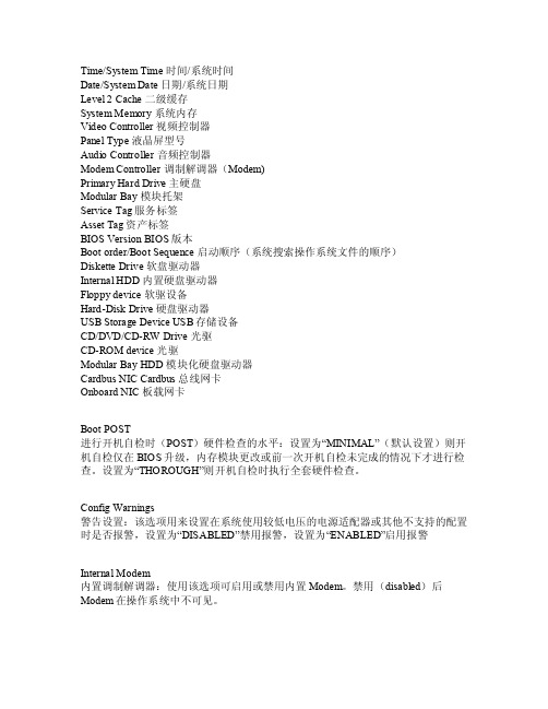
Time/S ystem Time时间/系统时间Date/Syste m Dat e 日期/系统日期Leve l 2 C ache二级缓存Syst em Me mory系统内存Vide o Con troll er 视频控制器Panel Type液晶屏型号Au dio C ontro ller音频控制器Mod em Co ntrol ler 调制解调器(Modem)Pr imary Hard Driv e 主硬盘Mod ularBay 模块托架Servi ce Ta g 服务标签As set T ag 资产标签B IOS V ersio n BIO S版本Bootorder/Boot Sequ ence启动顺序(系统搜索操作系统文件的顺序)Disk etteDrive软盘驱动器In terna l HDD内置硬盘驱动器Flopp y dev ice 软驱设备Hard-DiskDrive硬盘驱动器US B Sto rageDevic e USB存储设备CD/D VD/CD-RW D rive光驱C D-ROM devi ce 光驱Mod ularBay H DD 模块化硬盘驱动器Ca rdbus NICCardb us 总线网卡O nboar d NIC板载网卡B oot P OST 进行开机自检时(PO ST)硬件检查的水平:设置为“MINIM AL”(默认设置)则开机自检仅在BIOS升级,内存模块更改或前一次开机自检未完成的情况下才进行检查。
设置为“T HOROU GH”则开机自检时执行全套硬件检查。
Con fig W arnin gs警告设置:该选项用来设置在系统使用较低电压的电源适配器或其他不支持的配置时是否报警,设置为“DISAB LED”禁用报警,设置为“EN ABLED”启用报警I ntern al Mo dem 内置调制解调器:使用该选项可启用或禁用内置Mode m。
Solaris 8 产品说明说明书

Solaris8(Intel平台版本)2/02发行说明Sun Microsystems,Inc.4150Network CircleSanta Clara,CA95054U.S.A.部件号码816-3444-112002年2月Copyright2002Sun Microsystems,Inc.901San Antonio Road,Palo Alto,California94303-4900U.S.A.版权所有。
本产品或文档受版权保护,其使用、复制、分发和反编译均受许可证限制。
未经Sun及其授权者事先的书面许可,不得以任何形式、任何手段复制本产品及其文档的任何部分。
包括字体技术在内的第三方软件受Sun供应商的版权保护和许可证限制。
本产品的某些部分可能是从Berkeley BSD系统衍生出来的,并获得了加利福尼亚大学的许可。
UNIX是由X/Open Company,Ltd.在美国和其它国家独家许可的注册商标。
Sun、Sun Microsystems、Sun标志、、AnswerBook、AnswerBook2、DiskSuite,HotJava,Java,JavaSpaces,JDK,JumpStart, OpenWindows,Solstice AdminSuite,Solstice AutoClient,Solaris Management Console,SunOS,XView,和Solaris是Sun Microsystems, Inc.在美国和其他国家的商标、注册商标或服务标记。
所有SPARC商标均按许可证授权使用,它们是SPARC International,Inc.在美国和其它国家的商标或注册商标。
带有SPARC商标的产品均以Sun Microsystems,Inc.PostScript是Adobe Systems,Incorporated的商标或注册商标,它们可能在某些司法管辖区注册。
EP2C8Q208C8中文资料(Altera)中文数据手册「EasyDatasheet - 矽搜」
Cyclone II器件手册,第1卷ii内容章修订日期............................................... ............................喜关于本手册............................................... .............................十三如何触点Altera ..........................................................................................................................十三印刷约定....................................................................................................................十三第一节Cyclone II器件系列数据表修订记录.................................................................................................................................... 1-1第1章简介简介............................................................................................................................................低成本嵌入式处理解决方案............................................ ......................................低成本DSP解决方案.................................................................................................................特征...................................................................................................................................................参考文献.........................................................................................................................文档修订历史记录.................................................................................................................1–1 1–1 1–1 1–2 1–9 1–9第2章Cyclone II架构功能说明.......................................................................................................................... 2-1逻辑元件....................................................................................................................................... 2-2LE操作模式........................................................................................................................ 2-4逻辑阵列模块................................................................................................................................ 2-7LAB互连............................................................................................................................ 2-8LAB控制信号......................................................................................................................... 2-8MultiTrack互联..................................................................................................................... 2-10行互连.......................................................................................................................... 2-10列互连.................................................................................................................... 2-12设备路由............................................................................................................................... 2-15全局时钟网络和锁相环.......................................... ..................................... 2-16专用时钟管脚..................................................................................................................... 2-20双用时钟引脚.............................................................................................................. 2-20全局时钟网络................................................................................................................... 2-21全局时钟网络分布.............................................. .............................................. 2-23锁相环.................................................................................................................................................. 2-25嵌入式存储器............................................................................................................................. 2-27内存模式............................................................................................................................... 2-30时钟模式.................................................................................................................................... 2-31M4K路由接口.................................................................................................................. 2-31iii内容嵌入式乘法器........................................................................................................................乘法器模式............................................................................................................................嵌入式乘法器路由接口.............................................. .......................................I / O结构及特点....................................................................................................................外部存储器接口.......................................................................................................可编程驱动强度.....................................................................................................漏极开路输出........................................................................................................................摆率控制...........................................................................................................................总线防护持..........................................................................................................................................可编程上拉电阻............................................. .................................................. ...高级I / O标准支持............................................ .................................................. ..高速差分接口............................................. .................................................系列片上端接.........................................................................................................I / O组........................................................................................................................................多电压I / O接口.................................................................................................................2–32 2–35 2–36 2–37 2–44 2–49 2–50 2–51 2–51 2–51 2–52 2–53 2–55 2–57 2–60第3章配置与测试IEEE标准. 1149.1(JTAG)边界扫描支持........................................... ..................................构造.........................................................................................................................................操作模式...................................................................................................................................配置计划......................................................................................................................... Cyclone II自动单粒子翻转检测........................................... ...........................定制电路....................................................................................................................软件界面.............................................................................................................................文档修订历史记录.................................................................................................................3–1 3–5 3–5 3–6 3–7 3–7 3–7 3–8第4章热插拔和上电复位简介............................................................................................................................................旋风II热插拔规格............................................ ................................................设备可以在电源时会驱动.......................................... ...........................................I / O引脚防护持三态电期间...................................... ......................................在Cyclone II器件热插拔功能实现......................................... ..............上电复位电路...................................................................................................................."唤醒"时间Cyclone II器件........................................ ...............................................结论..............................................................................................................................................文档修订历史记录.................................................................................................................4–1 4–1 4–2 4–2 4–3 4–5 4–5 4–7 4–7第5章直流特性和时序规范运行条件........................................................................................................................... 5-1单端I / O标准.......................................................................................................... 5-5差分I / O标准.............................................................................................................. 5-7DC特性不同针类型............................................ ......................................... 5-11片上端接规格............................................. .............................................. 5-12能量消耗........................................................................................................................... 5-13时序规格.......................................................................................................................... 5-14预,决赛时序规范............................................. ................................ 5-14演出.................................................................................................................................... 5-15 ivCyclone II器件手册,第1卷内容内部时序...............................................................................................................................Cyclone II时钟时序参数............................................. ..............................................时钟网络偏移加法器.......................................................................................................IOE可编程延迟.............................................................................................................不同I默认容性负载/ O标准......................................... .................I / O延迟.......................................................................................................................................最大输入和输出时钟频率............................................ ........................................高速I / O时序规格........................................... ............................................外部存储器接口规范.............................................. ....................................JTAG时序规范..........................................................................................................PLL时序规范............................................................................................................占空比失真.........................................................................................................................DCD测量技术............................................... .................................................. ..参考文献.......................................................................................................................文档修订历史记录...............................................................................................................5–18 5–23 5–29 5–30 5–31 5–33 5–46 5–55 5–63 5–64 5–66 5–67 5–68 5–74 5–74第6章参考和订购信息软体..................................................................................................................................................器件引脚输出.....................................................................................................................................订购信息...........................................................................................................................文档修订历史记录.................................................................................................................6–1 6–1 6–1 6–2第二节.时钟管理修订记录.................................................................................................................................... 6-1第7章锁相环在Cyclone II器件简介............................................................................................................................................ 7-1Cyclone II PLL硬件概述............................................. .................................................. ... 7-2PLL参考时钟产生.............................................. .................................................. ... 7-6时钟反馈模式....................................................................................................................... 7-10正常模式.................................................................................................................................. 7-10零延迟缓冲器模式................................................................................................................ 7-11无补偿模式............................................................................................................... 7-12源同步模式........................................................................................................... 7-13硬件特性.............................................................................................................................. 7-14时钟倍频和科.............................................. .................................................. .. 7-14可编程占空比........................................................................................................... 7-15移相实施.............................................. .................................................. .... 7-16控制信号................................................................................................................................ 7-17手动时钟切换............................................................................................................. 7-20时钟................................................................................................................................................ 7-21全局时钟网络................................................................................................................... 7-21时钟控制模块....................................................................................................................... 7-24全局时钟网络时钟源产生............................................ .......................... 7-26全局时钟网络掉电............................................. .............................................. 7-28vCyclone II器件手册,第1卷。
DCS画面英汉对照表资料

DCS画面英汉对照表- 1 -DCS画面(汽机部分)英汉对照表画面英文中文TURB EH OIL SYS(汽轮机抗燃油系统)EH OIL TANK 抗燃油箱LVL LL 油位低低值LVL OK 油位正常OIL SUPPLY 供油OIL-REF DEVICE 油再生装置- 2 -PDS H 差压高HP FLUID 高压控制油GEN H2 SYSTEM(发电机氢气系统)LEAK DETECT 泄漏检测CO2 SUPPLY CO2供气H2 SUPPLY H2供气RPL DETECT 气体置换检测装置H2 DRYER 氢气干燥器H2 LEAKAGE DETECT 氢气泄漏量检测GENERATOR 发电机ROTOR SEAL OIL(发电机转子密封油系统)AIR SIDE RTN OIL SOIL TNK 空气析出槽MN OTK 主油箱- 3 -TURB END 汽轮机端EXCI END 励磁端RETURN OIL 氢侧回油VACUUM OIL TNK 真空油箱CLG WTR 冷却水LOIL 润滑油MN OIL TK 主油箱STATOR COOLING WATER(发电机定子冷却水系统)MAKE UP WATER 补水DEMIN 离子交换器WATER TANK 定冷水箱TURB LUBE OIL SUPPLY(汽轮机润滑油系统)MAIN OIL PMP 主油泵- 4 -EOP 直流油泵TOP 交流油泵MSP 启动油泵#1 E-HTR #1电加热#2 E-HTR #2电加热TE H 温度高BRG OIL SUPPLY 轴承润滑油供油BRG LIFT PMP 顶轴油泵CONGTROL OIL 控制油TURB OIL/EQUIPMENT(汽轮机油系统/汽轮机设备)ROTOR SEAL OIL 转子密封油GENERATOR CLG H2 SYS 发电机氢冷系统STATOR CLG WTR 定子冷却水系统- 5 -GEN&TURB EQUIPMENT 发电机&汽轮机设备TURB EH OIL SUPPLY 汽轮机抗燃油系统TURB LUBE OIL SUPPLY 汽轮机润滑油系统STATOR TEMP1 定子温度1STATOR TEMP2 定子温度2TDBFP&BFPT B EQUIPMENT(B汽泵前置泵&B汽泵设备)BRG 轴承METAL TEMP 金属温度(缸温)X VIBRATION X方向振动Y VIBRATION Y方向振动BRG VIB H 轴承振动高一值BRG VIB HH 轴承振动高二值BOOSTER PUMP 启动泵(前置泵)- 6 -DRV END AXL BRG 驱动端辅助轴承FREE END AXL BRG 自由端辅助轴承FREE END THRST BRG 自由端推力轴承MTR DE AXL BRG 电机驱动端辅助轴承MTR FE AXL BRG 电机自由端辅助轴承TDBF PUMP 汽泵DRV END AXL BRG 驱动端辅助轴承FREE END AXL BRG 自由端辅助轴承THRST BRG INNER1 推力轴承内侧温度1 THRST BRG INNER2 推力轴承内侧温度2 THRST BRG OUTER1 推力轴承外侧温度1 THRST BRG OUTER2 推力轴承外侧温度2 SHELL TEMP 1 壳体温度1- 7 -SHELL TEMP 2 壳体温度2TURBINE 汽轮机PSN THRST BRG 固定端推力轴承(正向推力轴承)NEG THRST BRG 非驱动端推力轴承(反向推力轴承)AXIAL POSITION 1 轴向位移1AXIAL POSITION 2 轴向位移2 ECCENTRICITY 偏心度AXL PSN H 轴向位移高一值AXL PSN HH 轴向位移高二值ECC H 偏心度高- 8 -TDBFP&BFPT A EQUIPMENT(A汽泵前置泵&A汽泵设备)(与B汽泵前置泵&B汽泵设备画面相同)BFPT DRAIN SYSTEM(小汽轮机疏水系统)BPFT A LP TV BASE F A小机低压主汽门阀前疏水(机头侧)BPFT A LP TV BASE R A小机低压主汽门阀前疏水(阀座后)BPFT A LP GV SHELL A小机低压调阀阀座后疏水BPFT A 1ST CASING A小机第一级汽缸疏水BPFT A HP TV BASE F A小机高压主汽门阀前疏水(阀座前)BPFT A HP TV BASE R A小机高压主汽门阀前疏水(阀座后)- 9 -DRN H 疏水集管HDRN A 疏水集管ABPFT B LP TV BASE F B小机低压主汽门阀前疏水(机头侧)BPFT B LP TV BASE R B小机低压主汽门阀前疏水(阀座后)BPFT B LP GV SHELL B小机低压调阀阀后座疏水BPFT B 1ST CASING B小机第一级汽缸疏水BPFT B HP TV BASE F B小机高压主汽门阀前疏水(阀座前)BPFT B HP TV BASE R B小机高压主汽门阀前疏水(阀座后)BPFT HP V F 高压总电动门前- 10 -BPFT LP MV FRT-END 低压主汽门前疏水(机尾侧)BPFT LP MV FRT-HEAD 低压主汽门前疏水(机头侧)SUBFP EQUIPMENT(电泵设备)SUBFP BSTR PMP 电泵前置泵DRV END AXL BRG 驱动端辅助轴承FREE END AXL BRG 自由端辅助轴承THRST BRG INNER1 推力轴承内侧温度1 THRST BRG INNER2 推力轴承内侧温度2 THRST BRG OUTER1 推力轴承外侧温度1 THRST BRG OUTER2 推力轴承外侧温度2 SUBFP MOTOR 电泵电机BST PMP END BRG 前置泵端轴承HYD-CPLG END BRG 液力耦合器端轴承- 11 -SUBFP 电泵DRV END AXL BRG 驱动端辅助轴承FREE END AXL BRG 自由端辅助轴承THRST BRG INNER1 推力轴承内侧温度1 THRST BRG INNER2 推力轴承内侧温度2 THRST BRG OUTER1 推力轴承外侧温度1 THRST BRG OUTER2 推力轴承外侧温度2SUBFP(电泵)DEAER 除氧器SBP 前置泵HYDR COUP 液力耦合器#3 HP HEATER #3高加BLR WTR 锅炉给水- 12 -RH SPY 再热器SH SPY 过热器EQUIPMENT 设备(温度测点) LUBE OIL 润滑油(系统)SUBFP LUBE OIL(电泵润滑油系统)#1 BRG #1轴承#3 THUT BRG #3推力轴承SBP 前置泵HYDR-COUP 液力耦合器SUBFP 电泵LB OIL CLR 润滑油冷却器WK OIL CLR 工作油冷却器BFPT B LUBE OIL(B小汽轮机润滑油)- 13 -BFPT B B小汽轮机TDBFP B B汽泵OIL RETN 回油LUBE OIL TANK 润滑油箱BFPT STEAM&SEAL(小汽轮机蒸汽&密封)TURB GLAND 大机来密封蒸汽COND 凝结水(来减温水)HP CDSR 高压侧凝汽器#4 EXTR 四抽LP CDSR 低压侧凝汽器BFPT A A小机BFPT B B小机AUX STM 辅助蒸汽- 14 -MV STM 主蒸汽OV SPD 超速SPD H 转速高PDS H 差压高PS L 压力低BFPT A LUBE OIL(A小机润滑油)BFPT A A小汽轮机TDBFP A A 汽泵OIL RETN 回油LUBE OIL TANK 润滑油箱LVL L 液位低WTR LVL CTRL(水位控制)COND WTR MKUP TK 凝结水补水箱- 15 -CHEM WTR 化学除盐水来CDSR 凝汽器DEAR 除氧器SUBFP 电泵VACCUM 真空GEN LOAD 发电机功率SH P 过热蒸汽压力SH T 过热蒸汽温度RH T 再热蒸汽温度FW F 给水流量MN STM F 主蒸汽流量CD WTR F 凝结水流量DRUM 汽包- 16 -FEED WATER PUMP(给水泵)DEAER 除氧器BFPT A LOIL A小机润滑油BFPT B LOIL B小机润滑油SUBFP LOIL 电泵润滑油SUBFP 前置泵SUBFP EQUIPMENT 前置泵设备#1、2、3 HP HEATER #`1、2、3高加COND WTR 凝结水ECON 省煤器DRUM 汽包WTR LVL CTRL 水位控制BFPT DRAIN 小机疏水- 17 -BFPT B EQUIPMENT B小机设备BFPT A EQUIPMENT A小机设备BFPT STM&SEAL 小汽轮机蒸汽&密封系统RH ATMP 再热器减温水SH ATMP 过热器减温水CWP STR/BRG TEMP(给水泵定子/轴承温度)#1 CWP TEMP #1给水泵温度#1 CWP LEFT STR T1 #1给水泵左端温度1#1 CWP LEFT STR T2 #1给水泵左端温度2#1 CWP LEFT STR T3 #1给水泵左端温度3#1 CWP RIGHT STR T1 #1给水泵右端温度1#1 CWP RIGHT STR T2 #1给水泵右端温度2#1 CWP RIGHT STR T3 #1给水泵右端温度3- 18 -#1 CWP THRUST BRG T1 #1给水泵推力轴承温度1 #1 CWP THRUST BRG T2 #1给水泵推力轴承温度2 #1 CWP LEAD BRG T1 #1给水泵导向轴承温度1 #1 CWP LEAD BRG T2 #1给水泵导向轴承温度2 #1 CWP DOWN BRG T #1给水泵下轴承温度#2 CWP TEMP #2给水泵温度#2 CWP LEFT STR T2 #2给水泵左端温度1#2 CWP LEFT STR T2 #2给水泵左端温度2#2 CWP LEFT STR T3 #2给水泵左端温度3#2 CWP RIGHT STR T2 #2给水泵右端温度1#2 CWP RIGHT STR T2 #2给水泵右端温度2#2 CWP RIGHT STR T3 #2给水泵右端温度3#2 CWP THRUST BRG T2 #2给水泵推力轴承温度1- 19 -#2 CWP THRUST BRG T2 #2给水泵推力轴承温度2 #2 CWP LEAD BRG T2 #2给水泵导向轴承温度1 #2 CWP LEAD BRG T2 #2给水泵导向轴承温度2 #2 CWP DOWN BRG T #2给水泵下轴承温度COND PMP STR/BRG TEMP(凝结水泵定子/轴承温度)#1 COND PMP TEMP #1凝结水泵温度#1 CD PMP TRST BRG T1 #1凝结水泵推力轴承温度1 #1 CD PMP TRST BRG T2 #1凝结水泵推力轴承温度2 #1 CD PMP TRST BRG T3 #1凝结水泵推力轴承温度3 #1 CD PMP MTR U REEL T #凝结水泵U相绕组温度#1 CD PMP MTR V REEL T #1凝结水泵V相绕组温度#1 CD PMP MTR W REEL T #1凝结水泵W相绕组温度#2 COND PMP TEMP #2凝结水泵温度- 20 -#2CD PMP TRST BRG T1 #2凝结水泵推力轴承温度1 #2CD PMP TRST BRG T2 #2凝结水泵推力轴承温度2 #2CD PMP TRST BRG T3 #2凝结水泵推力轴承温度3 #2 CD PMP MTR U REEL T #2凝结水泵U相绕组温度#2 CD PMP MTR V REEL T #2凝结水泵V相绕组温度#2 CD PMP MTR W REEL T #2凝结水泵W相绕组温度INDUSTRY WATER(辅机冷却水)CCW 循环水MKWTR 补水TURB LUB OIL CLR 主机润滑油冷却器EH OIL CLR 抗燃油冷却器AIR CMPSR 空压机CLG TWR 循环冷却水- 21 -BFPT OIL CLR A 小机冷油器ABFPT OIL CLR B 小机冷油器BGEN H2 CLR 发电机氢气冷却器GEN STR CLR A 发电机定冷水冷却器A GEN STR CLR B 发电机定冷水冷却器B MDFWP LB OIL CLR 电泵润滑油冷却器MDFWP WK OIL CLR 电泵工作油冷却器MILL A-E OIL CLR A-E磨煤机冷却器AH BRG 空气预热器(导向)轴承PA FAN OIL CLR 一次风机冷油器FD FAN OIL CLR 送风机冷油器INTERM-BLDWN 定排扩容器COND CIRC WATER(循环水系统)- 22 -COND VAC 凝汽器真空WTR PIT 集水坑CLG TOWER 凉水塔BALL CLN B PROGRAM B胶球清洗装置(程序)BALL CLN A PROGRAM A胶球清洗装置(程序)EXTH TEMP 高排温度CD WTR T 凝结水温度START 启动STOP 停止FAULT 故障OVLD 过负荷COND VACUUM(凝汽器真空系统)HP COND 高压侧凝汽器- 23 -LP COND 低压侧凝汽器PDS H 差压高SEPARATOR 气水分离器LVL H 液位高LVL L 液位低INDUS WTR 辅机冷却水COND WTR 凝结水(补水)CIRC WATER(循环水系统)CDSR 凝汽器STORE WATER POOL 蓄水池CLG TWR 凉水塔FLOW L 流量低#1 CWP MTR #1循环水泵电机- 24 -#2 CWP MTR #2循环水泵电机TOPEN 顺控开LOC 就地TCLS 顺控关MID 中间位(15度)CLS 全关位CWP STR/BRG T 循环水泵定子/轴承温度COND WATER(凝结水)COND WTR MKUP TK 凝结水补水箱GLAND 轴封POLISH 精处理DRN 疏水CHEM WTR 化学水- 25 -#7/#8 LP #7/#8低加DEAR 除氧器BLR CIR PMP 炉水循环泵CIRC WTR 循环水INDUSTRY WTR 工业水COND VAC 凝汽器真空CD TANK 热井CDSR CLG WTR 凝汽器冷却水CD PUMP WDG 凝结水泵绕组DEARATOR(除氧器)#4EXTR 四抽DRN 疏水AUX STM 辅助蒸汽- 26 -FW PMP 给水泵DEARER STOR TK 除氧器储水箱CDSR 凝汽器RTN WTR 回水DEARER FILL WTR 除氧器上水#3 HP #3高加#5 LP #5低加#7/#8HEATER(#7/#8加热器)#6 LP #6低加GLAND 轴加CDSR 凝汽器EXPDR 危急疏水(疏水扩容器)- 27 -#5/#6HEATER(#5/#6加热器)(与#7/#8加热器同)HP HEATER(高加)EXTR 抽汽ECON 省煤器BFWP 锅炉给水泵EXPDR 危急疏水EXTR/HEATER(抽汽/加热器)HP 高压缸IP 中压缸LP A 低压缸ALP B 低压缸B#1 HTR #1加热器- 28 -#2 HTR #2加热器#3 HTR #3加热器DEAER 除氧器#5 HTR #5加热器#6 HTR #6加热器#7A HTR #7A加热器#8A HTR #8A加热器#7B HTR #7B加热器#8B HTR #8B加热器AUX STM 辅助蒸汽TURB DRAIN OVERVIEW(汽轮机疏水全貌)BDV 紧急排放阀TURB EQUIP 汽轮机设备- 29 -BFPT DRN 小汽轮机疏水HP BYPASS 高压旁路LP BYPASS 低压旁路COLD RH DRN 冷再疏水HP HTR 高加#5/#6 HEATER #5/#6加热器#7/#8 HTR #7/#8加热器TURBINE BASE TEMP(汽轮机缸温)HP 高压缸IP 中压缸RH 再热蒸汽SH 过热蒸汽TURBINE DRAIN(汽轮机轴封)- 30 -COND 凝结水来AUX STM 辅助蒸汽COLD RH 冷再MN STM 主蒸汽PDS H 差压高CDSR 凝汽器GLAND STM HTR 轴封加热器AUX STEAM(辅汽联箱)HP AUX STEAM 高压辅汽LP AUX STEAM 低压辅汽CHEM 化学GLAND 轴封AUX BLR 启动炉- 31 -COLD RH 冷再DEARER 除氧器#4 EXTR 四抽AIR STEAM 暖通#1 AH #1机暖风器LP EXPR 低压疏水扩容器TURBINE DRN(汽轮机疏水)DRN HDR A 疏水集管A DRN HDR B 疏水集管BHP/LP BYPASS(高压/低压旁路)COND WTR 凝结水FW 给水CDSR A/B 凝汽器A/B- 32 -LP A/B 低压缸A/BIP 中压缸RH 再热蒸汽SH 过热蒸汽TURB STEAM(汽轮机蒸汽系统)GLD STM 轴封蒸汽EXPDR 疏水扩容器BFPT 小汽轮机RH SH 再热蒸汽过热蒸汽LVL H/L 液位高/低COND 凝结水DRN 疏水AUX 辅助蒸汽- 33 -UNIT MOTOR MONITORING(电机主控单元)COND WTR PMP 凝结水泵CIRC WTR PMP 循环水泵STATOR CLG PMP 定子冷却水泵SUBFP 电泵TDBF PMP 汽泵前置泵TURB EN OIL PMP 汽轮机EH油泵ROTOR SEAL OIL PMP 发电机密封油泵VACUUM PMP 真空泵CD MKUP PMP 凝汽器补充水泵DEAR FILL PMP 除氧器上水泵LUBE OIL PMP 汽轮机润滑油泵INDUSTRY WTR PMP 辅机冷却水水泵- 34 -UNIT MASTER(单元主控)ADS MODE 自动调度系统方式ADS PERM 自动调度系统方式运行ADS NORMAL 自动调度系统正常RB 快速减负荷MFT 锅炉主燃料跳闸ID 引风机FWP 给水泵FD 送风机PA 一次风机FUEL 燃料FG AH 空预器BREAKER 断路器- 35 -CWP 循环水泵STOP INC 闭锁增STOP DEC 闭锁减TO MAX 已到最大值TO MIN 已到最小值FIX\SLIDE 定压\滑压运行方式MAN 手动BF 锅炉跟随CCS 协调控制TF 汽机跟随FIX PRESS SET 压力设定(定压)SLIDE PRE SET 滑压设定HEAT VALUE 热应力预算- 36 -B-MAST 锅炉主控T-MAST 汽机主控FUEL-MAST 燃料控制FUEL MAN 燃料手动DEH LOCAL DEH控制UNIT LOAD 机组负荷RATE SET 升速率设定FRQ INF 频率信息LOAD DMD 负荷调节GEN LOAD 发电机负荷GV POSITION 高调阀位置SPEED 转速PRESS DMD 压力调节- 37 -MN STM PRESS 主蒸汽压力SH STM PRESS 过热蒸汽压力RH STM PRESS 再热蒸汽压力FURNACE PRESS 炉膛压力TOTAL COAL 总煤量TOTAL AIR 空气总量O2氧量DRUM LVL 汽包水位VACUUM 真空DCS画面(锅炉部分)英汉对照表- 38 -BOILER WATER SYSTER:炉水系统BLR CLC PMP INLEF HEADER 炉水泵入口集箱锅炉水冷壁上集箱BOILER WATER WALL UPPERHEADER锅炉水冷壁下集箱BOILER WATER WALLLOWER HEADERBOILER WATER CIRC PUMP 炉水循环泵INTERMITTENT BLOW DOWN 定期排污DRUN WALL TEMPERATURE 汽包壁温DEAR FILL WTR PMP 除氧器上水泵COND PMP 凝结水泵FW PMP 给水泵HP HTR 高压加热器- 39 -DRAIN/BLOWDOWN:疏水/排污FRONT WALL SH A 后烟道前墙下集箱A侧FRONT WALL SH B 后烟道前墙下集箱B侧BACK WALL SH A 后烟道后墙下集箱A侧BACK WALL SH B 后烟道后墙下集箱B侧TOP PIPE INLET 顶棚管入口FW PLPE 给水母管STM AIR HTR 暖风器ECON 省煤器FRONT WALL LOW HDR 前水冷壁下集箱BACK WALL LOW HDR 后水冷壁下集箱CONT BLOW DOWN 连续排污INTERM BLOWDOWN 定期排污- 40 -WTR PIT 定排水池AIR FLUE GAS SYSTEM :风烟系统ID FAN CONTROL 引风机控制SURGE 喘振ID FAN LUBE OIL 引风机润滑油ID FAN LUBE OIL TANK 引风机油箱OIL RTN 回油BIAS 偏差PA FAN 一次风机FD FAN 送风机ID FAN 吸风机AIR PRE HTR 空气预热器STM AIR HEATER 暖风器- 41 -AUX STM 辅助蒸汽PA ,SA 一次风,二次风E-P A A 电除尘FD FAN CONTROL 送风机控制FD FAN LUBE OIL 送风机润滑油GAS OUT 烟气出口FURNACE 炉膛STM FLOW 蒸汽流量STACK 烟囱LEFT GAS TEMP DET 左侧烟温探针RIGHT GAS TEMP DET 右侧烟温探针FURNACE PRESSURE H 炉膛压力高FURNACE PRESSURE LL 炉膛压力低二值- 42 -FURNACE 炉膛RUN,FWD ,BCK 运行,前进,后退RMT 远方{遥控}F-PLT SH 前屏过热器R-PLT SH T 后屏过热汽温度FINAL RH 末级再热器FINAL SH 末级过热器PRI SH 初级过热器ECON 省煤器AIR HTR 空预器SH ATTEMP:过热器减温水FW PMP 给水泵FW FLOW 给水流量- 43 -MN STM P 主汽压力TUBE METAL T 管子壁温SEP-PLATE SH TUBE T 分隔屏过热汽壁温BACK-PLATE SH TUBE T 后屏过热汽壁温PRI-SH TUBE MTL TEMP 初级过热汽壁温RH ATTEMP 再热器减温COLD RH 冷再HOT RH 热再FW PMP MID SUCT 给水泵中间抽头RH 再热器BNR SWING SETPOINT 燃烧器摆角设置LEFT METAL T 左侧金属温度RIGHT METAL T 右侧金属温度- 44 -DRN TANK 疏水扩容器DRUM 汽包DEAR 除氧器COMBUSTION:燃烧系统OIL BURNER 油燃烧器SECOND AIR 二次风FLM SCAN/SL FAN 火检冷却风/密封封机FIREOUT AIR CTRL 燃尽风控制#1CORNER #1角FURNACE STBLOW 炉膛吹灰GAS SOOTBLOW 烟道吹灰SOOTBLOW STEAM 吹灰蒸汽LEFT SIDE WALL 左侧水冷壁- 45 -RIGHT SIDE WALL 右侧水冷壁DRN WTR 疏水AIR PRE HTR A/B:空气预热器A/B MAIN MTR 主电机STANDBY MTR 辅助电机AH SOOTBLOWING 空预器吹灰AUX CLG WATER 辅机冷却水FRBR WTR 消防水COM AIR 压缩空气#1/#2SPD SSR FLT #1/#2转速传感器故障FIER ALM PWR FLT 火灾报警电源故障MK WTR 补给水AIR CMPSR 空压机- 46 -SPEED 转速MILL OVERV磨煤机总貌COAL HOPPER 煤斗MILL C LOIL C 磨煤机润滑油MILL C CL LVL C磨煤机料位INERT STM 充惰蒸汽PLGD 给煤机堵煤WITH CL 皮带上有煤CD/HT PA 冷/热一次风MILL LUBE OIL 磨煤机润滑油OIL TANK 油箱RUNING 运行STOPE 停止- 47 -COAL F 煤量DRUM LVL 汽包水位SECOND AIR CONTROL 二次风控制磨电机前/后轴承温度MILL MTR FRONT/REAR BRGTMOTOR WDG T 电机线圈温度MTR FRONT/REAR BRG T 电机前后/轴承温度PURG RELEASE 吹扫解除PURG READY 吹扫准备PURG FINISH 吹扫结束OIL STN FLT 油过滤器故障START 启动CTRL AIR 控制气源- 48 -AIR TANK 储气罐PURGE AIR 吹扫气源FDR 给煤机OV T 给煤机温度高FUEL OIL SYSTEM燃油系统DISCHARGE OIL 卸油FUEL OIL 燃油COL OIL TANK 集油池CONSUME STM 加热蒸汽OIL-WTR SEPARATOR 油/水分离器OFT 燃油跳闸OFT RESET 油燃料跳闸复位FULE OIL LEAK TEST 燃油泄露试验- 49 -FOIL 供油HYDR OIL 液压油DCS画面(电气部分)英汉对照表ELECTRICITY SYSTEM(电气系统)TRANSFORMER(变压器)锅炉变BOILER TRANSFORMER(BT)TURBINE TRANSFORMER汽机变(TT)ESP TRANSFORMER(EST)电除尘变ETO 电除尘备变- 50 -。
金蝶数据库

表中文名 凭证字表 凭证分录表 凭证表 系统用户信息表 单位类别表 系统参数表 供应商表 辅助资料类别表 辅助资料表 仓库表 结算方式表 计量单位表 上机日志标准信息表 上机日志信息表 基础资料权限表 核算项目附表信息描述表 基础资料类别表 物料表 备注资料表 职员表 部门表 币别表 科目表 权限控制表 用户组权限表 用户组权限类表 对象权限表 对象权限类型表 对象类型表 附件管理表 自动增加表 编码规则主表 编码规则明细表 编码规则当前值表表 编码规则分配表表 数据类型定义表 数据灌入模块表 数据灌入中间表 数据灌入字段描述表 自动步长编码表 功能互斥表 基础资料相关属性 对象参考表 系统枚举表 万能报表表描述表 万能报表用户定义表
系统ID 表ID 表名 0 0 t_VoucherGroup 0 1 t_VoucherEntry 0 2 t_Voucher 0 3 t_User 0 4 t_UnitGroup 0 5 t_SystemProfile 0 6 t_Supplier 0 7 t_SubMesType 0 8 t_SubMessage 0 9 t_Stock 0 10 t_Settle 0 11 t_MeasureUnit 0 12 t_LogFunction 0 13 t_Log 0 14 t_ItemRight 0 15 t_ItemPropDesc 0 16 t_ItemClass 0 17 t_ICItem 0 18 t_Exp 0 19 t_Emp 0 20 t_Department 0 21 t_Currency 0 22 t_Account 0 23 t_AccessControl 0 24 t_GroupAccess 0 25 t_GroupAccessType 0 26 t_ObjectAccess 0 27 t_ObjectAccessType 0 28 t_ObjectType 0 29 t_Accessory 0 30 t_AutoNumber 0 31 t_CodeRule 0 32 t_CodeRuleDetail 0 33 t_CodeRuleValue 0 34 t_CodeTypeFP 0 35 t_DataTypeInfo 0 36 t_dls_moduel 0 37 t_dls_TableList 0 38 t_dls_TableStruct 0 39 t_Identity 0 40 t_Mutex 0 41 t_BaseProperty 0 42 t_ObjectRefs 0 43 t_SystemEnum 0 44 t_TableDescription 0 45 t_UserDefineRpt
致远A8数据字典_操作日志

BIGINT VARCHAR(1000) VARCHAR(1000) VARCHAR(1000) VARCHAR(1000) VARCHAR(1000) VARCHAR(1000) DATETIME
国际化 0 号参数 国际化 1 号参数 国际化 2 号参数 国际化 3 号参数 国际化 4 号参数 国际化 5 号参数
流程日志表 (v3x_process_log) 值域 描述
工作流过程实例 ID 工作流实例中的节点 ID 取值范围见数据字典
用友致远协同办公系统-设计文档
action_user_id param0 param1 param2 param3 param4 param5 action_date
操作人 操作时间 操作描述 0 操作描述 1 操作描述 2 操作描述 3 操作描述 4 操作描述 5
日志组件表 (v3x_app_log) 值域 描述
VARCHAR(255) VARCHAR(255) TEXT VARCHAR(255) VARCHAR(255) VARCHAR(255) VARCHAR(255) DATETIME
数据表 字段名 id process_id activity_id action_id 中文名 主键 ID 流程 ID 节点 ID 操作类型 类型 BIGINT BIGINT BIGINT INT
用友致远协同办公系统-设计文档
1.
操作日志表间关系示意图
Table Name
v3x_operation_log
中文名 操作日志记录表 日志组件表 流程日志表
描述 记录整个 A8 系统的操作日志信息。
v3x_app_log v3x_process_log
2.
操作日志数据表详细描述
sysfonts 0.8.8 软件说明说明书

Package‘sysfonts’October14,2022Type PackageTitle Loading Fonts into RVersion0.8.8Date2022-03-13Author Yixuan Qiu and authors/contributors of theincluded fonts.Seefile AUTHORS for details.Maintainer Yixuan Qiu<*******************>Description Loading system fonts and Google Fonts<https:///>into R,in order tosupport other packages such as'R2SWF'and'showtext'.Suggests curl,jsonliteCopyright seefile COPYRIGHTSSystemRequirements zlib,libpng,FreeTypeURL https:///yixuan/sysfontsBugReports https:///yixuan/sysfonts/issuesLicense GPL-2RoxygenNote7.1.2NeedsCompilation yesRepository CRANDate/Publication2022-03-1313:40:02UTCR topics documented:font_add (2)font_add_google (4)font_families (6)font_families_google (7)font_files (8)font_info_google (9)font_paths (10)Index111font_add Add New Font Families to’sysfonts’DescriptionThe two versions of this function are equivalent,but the"underscore"naming is preferred.This function registers new font families that can be used by package showtext and the SWF device in package R2SWF.Currently supported formats include but not limited to TrueType fonts(*.ttf, *.ttc)and OpenType fonts(*.otf).Usagefont_add(family,regular,bold=NULL,italic=NULL,bolditalic=NULL,symbol=NULL)font.add(family,regular,bold=NULL,italic=NULL,bolditalic=NULL,symbol=NULL)Argumentsfamily a character string of maximum200-byte size,indicating the family name of the font.See"Details"for further explanation.regular path of the fontfile for"regular"font face.This argument must be specified asa character string and cannot be missing.bold path of the fontfile for"bold"font face.If it is NULL,the function will use the value of argument regular.italic,bolditalic,symboldittoDetailsIn R graphics device,there are two parameters combined together to select a font to show text.par("family")is a character string giving a name to a series of font faces.Here series implies that there may be different fonts with the same family name,and actually they are distinguished bythe parameter par("font"),indicating whether it is regular,bold,or italic,etc.In R,par("font") is an integer from1to5representing regular,bold,italic,bold italic,and symbol,respectively.In sysfonts package,there are three default font families,sans,serif,and mono,each withfive font faces as mentioned above.If one wants to use other font families,the function font_add() needs to be called to register new fonts.Note that the family argument in this function can be an arbitrary string that does not need to be the real font name.The specified family name will be used in functions like par(family="myfont")and text("Some text",family="myfont").The Examples section shows a complete demonstration of the usage.Tofind the fontfile of argument regular(and the same for other font faces),this function will first check the existence of the specified path.If not found,file will be searched in the directories returned by font_paths()in turn.If thefile cannot be found in any of the locations,an error will be issued.ValueA character vector(invisible)of currently available font family names.Author(s)Yixuan Qiu<https://statr.me/>See AlsoSee par()for explanation of the parameters family and font.Examples##Not run:##Example:download the font file of WenQuanYi Micro Hei,##add it to SWF device,and use it to draw text in swf().##WenQuanYi Micro Hei is an open source and high quality##Chinese(and CJKV)font.wd=setwd(tempdir())ft.url="/projects/wqy/files/wqy-microhei"ft.url=paste(ft.url,"0.2.0-beta/wqy-microhei-0.2.0-beta.tar.gz",sep="/")download.file(ft.url,basename(ft.url))##Extract and add the directory to search pathuntar(basename(ft.url),compressed="gzip")font_paths("wqy-microhei")##Register this font file and assign the family name"wqy"##Other font faces will be the same with regular by defaultfont_add("wqy",regular="wqy-microhei.ttc")##A more concise way to add font is to give the path directly,##without calling font_paths()#font_add("wqy","wqy-microhei/wqy-microhei.ttc")##List available font familiesfont_families()if(require(R2SWF)){##Now it shows that we can use the family"wqy"in swf()swf("testfont.swf")##Select font family globallyop=par(family="serif",b=2)##Inline selecting fontplot(1,type="n")text(1,1,intToUtf8(c(20013,25991)),family="wqy",font=1,cex=2)dev.off()swf2html("testfont.swf")}setwd(wd)##End(Not run)font_add_google Load Google Fonts into’sysfonts’DescriptionThe two versions of this function are equivalent,but the"underscore"naming is preferred.This function will search the Google Fonts repository(https:///)for a spec-ified family name,download the proper fontfiles,and then add them to sysfonts.This function requires the jsonlite and curl packages.Usagefont_add_google(name,family=name,regular.wt=400,bold.wt=700,repo="/",db_cache=TRUE,handle=curl::new_handle())font.add.google(name,family=name,regular.wt=400,bold.wt=700,repo="/",handle=curl::new_handle())Argumentsname name of the font that will be searched in Google Fontsfamily specifies the family name of this font in R.This can be any string,not neces-sarily the same as name.The value of this parameter will be used in R plottingfunctions.See the example code below.regular.wt font weight for the regular font face,usually400bold.wt font weight for the bold font face,usually700repo the site that hosts the fontfiles.Default is the official repository / provided by Google Fonts.db_cache whether to obtain font metadata from a cache ing cache is typicallyfaster,but not as update-to-date as using the official API.If db_cache is set toFALSE,then metadata are retrieved from the Google Fonts API.handle a curl handle object passed to curl::curl_download().DetailsThere are thousands of open source fonts in the Google Fonts repository(https://fonts.google.com/).This function will try to search the font family specified by the name argument,and thenautomatically download the fontfiles for all possible font faces("regular","bold","italic"and"bolditalic",but no"symbol").If fonts are found and downloaded successfully,they will be also added tosysfonts with the given family name.Author(s)Yixuan Qiu<https://statr.me/>See Alsofont_families_google()Examples##Not run:font_add_google("Alegreya Sans","aleg")if(require(showtext)){wd=setwd(tempdir())pdf("google-fonts-ex.pdf")showtext_begin()par(family="aleg")6font_families plot(0:5,0:5,type="n")text(1:4,1:4,"Alegreya Sans",font=1:4,cex=2)showtext_end()dev.off()setwd(wd)}##End(Not run)font_families List Font Families Loaded by’sysfonts’DescriptionThe two versions of this function are equivalent,but the"underscore"naming is preferred.This function lists font families currently available that can be used by R2SWF and showtext packages.Usagefont_families()font.families()DetailsBy default there are three font families loaded automatically,i.e.,"sans","serif"and"mono".If one wants to use other fonts,font_add()needs to be called to register new fonts by specifying a family name and corresponding fontfiles.See font_add()for details about the meaning of"family name"in this context,as well as a complete example of registering and using a new font.ValueA character vector of available font family names.Author(s)Yixuan Qiu<https://statr.me/>See Alsofont_add()Examplesfont_families()font_families_google7 font_families_google List Font Families Available in Google FontsDescriptionThe two versions of this function are equivalent,but the"underscore"naming is preferred.This function lists family names of the fonts that are currently available in Google Fonts.Whenrunning this function for thefirst time,it may take a few seconds to fetch the font informationdatabase.This function requires the jsonlite and curl packages.Usagefont_families_google(db_cache=TRUE,handle=curl::new_handle())font.families.google()Argumentsdb_cache whether to obtain font metadata from a cache ing cache is typicallyfaster,but not as update-to-date as using the official API.If db_cache is set toFALSE,then metadata are retrieved from the Google Fonts API.handle a curl handle object passed to curl::curl_download()and curl::curl_fetch_memory().ValueA character vector of available font family names in Google Fonts.Author(s)Yixuan Qiu<https://statr.me/>See Alsofont_add_google()Examples##Not run:font_families_google()##End(Not run)8font_files font_files List Font Files Available in the Search PathsDescriptionThe two versions of this function are equivalent,but the"underscore"naming is preferred.This function lists fontfiles in the search path that can be loaded by font_add().Currently sup-ported formats include TrueType fonts(*.ttf,*.ttc)and OpenType fonts(*.otf).Usagefont_files()font.files()ValueA data frame containing the following information of the fontfiles:path The directory that the fontfile is located in.file File name of the font.family Family name.face Font face.version Version of the font.ps_name PostScript font name.Author(s)Yixuan Qiu<https://statr.me/>See Alsofont_paths(),font_add()Examples##Not run:font_files()##End(Not run)font_info_google9 font_info_google Display Information of Available Google FontsDescriptionThis function returns a data frame that contains the metadata of font families available in GoogleFonts,for example the family name,available font face variants,the version number,etc.Whenrunning this function for thefirst time,it may take a few seconds to fetch the database.Thisfunction requires the jsonlite and curl packages.Usagefont_info_google(db_cache=TRUE,handle=curl::new_handle())Argumentsdb_cache whether to obtain font metadata from a cache ing cache is typicallyfaster,but not as update-to-date as using the official API.If db_cache is set toFALSE,then metadata are retrieved from the Google Fonts API.handle a curl handle object passed to curl::curl_download()and curl::curl_fetch_memory().ValueA data frame containing metadata of Google Fonts.Author(s)Yixuan Qiu<https://statr.me/>See Alsofont_families_google()Examples##Not run:font_info_google()##End(Not run)10font_paths font_paths Get/Set Font Search PathsDescriptionThe two versions of this function are equivalent,but the"underscore"naming is preferred.This function gets/sets the search paths for fontfiles.See font_add()for details about how sys-fonts looks for fontfiles.There is also a complete example showing the usage of these functions in the help page of font_add().Usagefont_paths(new)font.paths(new)Argumentsnew a character vector indicating the search paths to be prepended.If the argument is missing,the function will return the current search paths.DetailsDefault search paths will be assigned when package is loaded:•For Windows,it is%windir%\Fonts,usually expanded into C:\Windows\Fonts•For Mac OS,default paths are/Library/Fonts and~/Library/Fonts and their subdirecto-ries•For Linux and other Unix-like OS,/usr/share/fonts,/usr/local/share/fonts,~/.fonts, ~/.local/share/fonts,and their subdirectoriesValueThe updated search paths.Author(s)Yixuan Qiu<https://statr.me/>Indexfont.add(font_add),2font.add.google(font_add_google),4font.families(font_families),6font.families.google(font_families_google),7font.files(font_files),8font.paths(font_paths),10font_add,2,6,8,10font_add_google,4,7font_families,6font_families_google,5,7,9font_files,8font_info_google,9font_paths,3,8,10par,311。
SYS-2020产品说明书
低音炮 ................................................................................................................................. 1
r
t
播放 ..............................................................................................................................4
×:在该零部件中至少一种均质材料中的有害物质的含量超过在GB/T 26572标准规定的限量要求(×判定:包括EU RoHS的豁免项目)
多溴二苯醚 (PBDE)
○
○ ○ ○
○
此标志是根据2016年1月6日颁布的「电器电子产品有害物质限制使用管理 办法」,以及「电子电气产品有害物质限制使用标识要求」,适用于在中 国销售的电子电气产品的环保使用期限。 在此产品相关的安全和使用上遵守注意事项,在从生产日期起计算的此年 限内,产品中的有害物质不会往外泄漏,或者引起突然变异而给环境污 染,人体或财产带来重大影响。 另外,包装在一起的电池等消耗品的环保期限是技术寿命5年。 适当地使用完后废弃的情况,请协助遵守各自治体的电子电气产品回收· 再利用相关的法律·规定。
cisco asyncos 8.0.8 for web 版本说明说明书

思科系统公司Cisco AsyncOS 8.0.8 for Web 版本说明本文档累积了针对所有思科网络安全设备 AsyncOS 8.0.x 版本的说明信息。
发布日期:2014 年 1 月 27 日修订日期:2016 年 7 月 18 日目录•此版本中的新增功能(第 1 页)•升级路线(第 6 页)•升级前要求(第 8 页)•安装和升级说明(第 8 页)•升级 AsyncOS for Web (第 11 页)•文档更新(第 11 页)•有关已知和已解决问题的最新信息(第 15 页)•相关文档(第 15 页)•支持(第 16 页)此版本中的新增功能•版本 8.0.8 (GD) 中的新增功能(第 2 页)•版本 8.0.7 中的新增功能(第 2 页)•版本 8.0.6 中的新增功能(第 3 页)•版本 8.0.5 中的新增功能(第 3 页)•版本 8.0.0 中的新增功能(第 4 页)2Cisco AsyncOS 8.0.8 for Web 版本说明此版本中的新增功能版本 8.0.8 (GD) 中的新增功能此版本的重大更改与禁用和启用 SSLv3 和临时椭圆曲线 Diffie-Hellman (ECDHE) 功能相关。
注意请将 Cisco AsyncOS for Web 用户指南 v8.0.6 与此版本结合使用。
版本 8.0.7 中的新增功能此版本属于维护版本,因此并未增加新功能。
功能 说明SSL 配置为获得增强的安全性,可以对多个服务启用和禁用 SSLv3。
在禁用 SSLv3 的情况下,服务会使用 TLSv1.0。
您可以对设备管理 Web 用户界面、代理服务(包括安全客户端的 HTTPS 代理和凭据加密)、安全 LDAP 服务(包括身份验证、外部身份验证、SaaS SSO 和安全移动)以及更新服务启用或禁用 SSLv3。
使用 Web 界面(“系统管理”(System Administration) >“SSL 配置”(SSL Configuration))或 CLI (sslconfig )。
SYS82000RKXDI-12中文资料
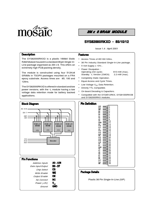
Package DetailsSYS82000RKXD - 85/10/12DescriptionFeaturesIssue 1.4 : April 2001•Access Times of 85/100/120ns.•36 Pin Industry Standard Single-In-Line package.• 5 Volt Supply ± 10% .•Power Dissipation :Operating (min cycle)610 mW (max).Standby -L Version (CMOS) 2.2 mW (max).•Completely Static Operation.•Equal Access and Cycle Times.•Low Voltage V CC Data Retention.•Directly TTL Compatible.•On-board Decoding & Capacitors.•Compatible with the SYS8512RKX, SYS81000RKXB and SYS82000RKX modules.The SYS82000RKXD is a plastic 16Mbit Static RAM Module housed in a standard 36 pin Single-In-Line package organised as 2M x 8. This offers an extremely high PCB packing density.The module is constructed using four 512Kx8SRAMs in TSOPII packages mounted on a FR4epoxy substrate. Access times are 85, 100 and 120ns.The SYS82000RKXD is offered in standard and low power versions, with the -L module having a low voltage data retention mode for battery backed applications.Plastic 36 Pin Single-In-Line (SIP)ParameterSymbol Test ConditionMin Typmax UnitI/P Leakage CurrentAddress,OE,WEILI 0V < V IN < V CC-4-4µA Output Leakage Current I LO CS = V IH, V I/O = GND to V CC -4-4µA Average Supply Current I CC1Min. Cycle, CS = V IL ,V IL <V IN <V IH --110mA Standby Supply CurrentTTL levels I SB1CS = V IH--12mA CMOS levelsI SB2CS > V CC -0.2V, 0.2<V IN <V CC -0.2V --8mA -L Version (CMOS)I SB3CS > V CC -0.2V, 0.2<V IN <V CC -0.2V --400µA Output VoltageV OL I OL = 2.1mA --0.4V V OHI OH = -1.0mA2.4--VTypical values are at V CC =5.0V,T A =25o C and specified loading.Voltage on any pin relative to V SS V T (2)-0.3-7.0V Power Dissipation P T - 4.0-W Storage TemperatureT STG-55-125o CNotes :(1)Stresses above those listed may cause permanent damage to the device. This is a stress rating onlyand functional operation of the device at those or any other conditions above those indicated in the operational sections of this specification is not implied. Exposure to absolute maximum rating conditions for extended periods may affect device reliability.DC OPERATING CONDITIONS ParameterSymbolMinTypMaxUnitParameterSymbolMinTypMaxUnitSupply Voltage V CC 4.5 5.0 5.5V Input High Voltage V IH 2.2- V CC +0.3V Input Low VoltageV IL -0.3- 0.8V Operating Temperature(Commercial)T A 0-70o C (Industrial)T AI-40-85o CParameterSymbol Test ConditionmaxUnitInput Capacitance (Address,OE,WE)C IN1V IN = 0V 32pF I/P Capacitance (other)C IN2V IN = 0V 8pF I/O CapacitanceC I/OV I/O = 0V40pF* Input pulse levels: 0V to 3.0V * Input rise and fall times: 5ns* Input and Output timing reference levels: 1.5V * Output load: see diagram * V CC=5V±10%CC = 3.0V, CS > V CC I CCDR1 (2)T OP = 0°C to 40°C--220µA Chip Deselect to Data Retention Time t CDR See Retention Waveform 0--ns Operation Recovery Time t R See Retention Waveform5--msNotes(1)Typical figures are measured at 25°C.(2)This parameter is guaranteed not tested.-85 - 10 -12ParameterSymbol min max min max min maxUnitWrite Cycle Timet WC85-100-120-ns Chip Selection to End of Write t CW 75-80-100-ns Address Valid to End of Write t AW 75-80-100-ns Address Setup Time t AS 0-0-0-ns Write Pulse Width t WP 55-60-70-ns Write Recovery Time t WR 3-3-3-ns Write to Output in High Z t WHZ 030035040ns Data to Write Time Overlap t DW 35-40-45-ns Data Hold from Write Time t DH 0-0-0-ns Output active from end of writet OW5-5-5-ns-85 -10 -12ParameterSymbol min max min max min maxUnitRead Cycle Timet RC85-100-120-ns Address Access Time t AA -85-100-120ns Chip Select Access Time t ACS -85-100-120ns Output Enable to Output Valid t OE -45-50-60ns Output Hold from Address Change t OH 10-10-10-ns Chip Selection to Output in Low Z t CLZ 10-10-10-ns Output Enable to Output in Low Z t OLZ 5-5-5-ns Chip Deselection to O/P in High Z t CHZ 030035045ns Output Disable to Output in High Zt OHZ303545nsAC OPERATING CONDITIONSAddressDoutAC Read Characteristics Notes(1)WE is High for Read Cycle.(2)All read cycle timing is referenced from the last valid address to the first transition address.(3)t CHZ and t OHZ are defined as the time at which the outputs achieve open circuit conditions and are notreferenced to output voltage levels.(4)At any given temperature and voltage condition, t CHZ (max) is less than t CLZ (min) both for a given moduleand from module to module.(5)These parameters are sampled and not 100% tested.0VVccCSAC Write Characteristics Notes(1)All write cycle timing is referenced from the last valid address to the first transition address.(2)All writes occur during the overlap of CS and WE low.(3)If OE, CS, and WE are in the Read mode during this period, the I/O pins are low impedance state.Inputs of opposite phase to the output must not be applied because bus contention can occur.(4)Dout is the Read data of the new address.(5)OE is continuously low.(6)Address is valid prior to or coincident with CS and WE low, too avoid inadvertant writes.(7)CS or WE must be high during address transitions.(8)When CS is low : I/O pins are in the output state. Input signals of opposite phase leading to theoutput should not be applied.(9)Defined as the time at which the outputs achieve open circuit conditions and are not referenced tooutput voltage levels. These parameters are sampled and not 100% tested.Plastic 36 Pin Single-In-Line (SIP)SYS82000RKXDLI-85Speed85=85 ns10=100 ns12=120 nsTemperature Range Blank=Commercial TemperatureI=Industrial TemperaturePower Consumption Blank=Standard PartL=Low Power PartPackage RKXD=Plastic 36 Pin Single-In-Line(SIP)Organization82000=2M x 8Memory Type SYS=Static RAMNote :Although this data is believed to be accurate the information contained herein is not intended to and does not create any warranty of merchantibility or fitness for aparticular purpose.Our products are subject to a constant process of development. Data may be changed without notice.Products are not authorised for use as critical components in life support devices without the express written approval of a company director.。
嵌入式系统及应用-Expt8-ARM WatchDog

主模块:Main() 主模块
void Main(void) { MMU_Init(); ChangeClockDivider(1,1); // 1:2:4 ChangeMPllValue(0xa1,0x3,0x1); // FCLK=202.8MHz Port_Init(); Int_Init(); //中断系统初始化 中断系统初始化 spi_Init(); //spiled初始化 初始化 key_Init(ISR_Keypad); //键盘初始化 键盘初始化 Rtc_EnTick(TICK_COUNT_PER_SEC, ISR_RtcTick); //rtc:每秒中断一次 每秒中断一次 wdt_Init(10 * 20 * WDT_CLOCK_PER_50MS, FALSE, NULL); //watchdog = 10s while(1) { if((g_uiEvent & BIT_TICK) != 0) //秒事件 秒事件 { spi_LedDisplay(LED0, g_uiSecCount % 10, DOT_OFF); g_uiEvent &= ~BIT_TICK; } if((g_uiEvent & BIT_EINT4_7) != 0) { wdt_Reset(); //喂watchdog 喂 g_uiSecCount = 0; //秒计数清 秒计数清0 秒计数清 g_uiEvent &= ~BIT_EINT4_7; } } } //按键事件 按键事件
WatchDog应用 应用
嵌入式系统运行时受到外部干扰或者系统错误,程序 嵌入式系统运行时受到外部干扰或者系统错误, 有时会出现“跑飞” 导致整个系统瘫痪。 有时会出现“跑飞”,导致整个系统瘫痪。为了防止这 一现象的发生, 一现象的发生,在对系统稳定性要求较高的场合往往要 加入看门狗( 加入看门狗(WATCHDOG)电路。看门狗的作用就是 )电路。 当系统“跑飞”而进入死循环时,恢复系统的运行。 当系统“跑飞”而进入死循环时,恢复系统的运行。
新一代8位微控制器EFM8系列产品说明书
新闻稿Silicon Labs推出新一代8位微控制器迎接物联网时代-最新节能型EFM8 MCU系列产品为成本和空间受限的设计提供无与伦比的简便性、外设集成和性能-中国,北京-2015年3月2日-物联网(IoT)领域节能型微控制器解决方案供应商Silicon Labs(芯科科技有限公司,NASDAQ:SLAB)今日宣布推出新一代8位MCU系列产品,该产品旨在满足当今超低功耗、小尺寸的IoT应用。
Silicon Labs的新型EFM8 MCU系列产品包括三种类型高集成度、外设丰富的MCU,这些MCU特别针对高性价比、超低功耗电容式触摸控制和精简USB连接而进行了优化。
EFM8 MCU为嵌入式开发人员所能想到的所有8位应用提供了业内领先的简便性、能效、性能和成本节省的综合优势,应用涵盖家居和楼宇自动化、可穿戴、消费类电子、玩具、电机控制和工业IoT等。
HIS Technology公司MCU首席分析师Tom Hackenberg表示,“为了在可预见的未来保持MCU市场的蓬勃发展,领先的MCU供应商持续不断的推动8位解决方案在能耗和集成特性上的发展。
根据IHS的预测,8位市场规模在2015年将达到70亿美元,2018年将增长到78亿美元,市场份额继续超过每年MCU市场营收的三分之一以上。
这种稳定的增长归功于市场对于0.5美元以下MCU在价格、极小封装、超低功耗、较低软件开销和简化设计的需求,这些也是IoT设备的先决条件。
Silicon Labs所设计的新型EFM8系列产品在这些关键应用领域中都具有最佳的特性和功能。
EFM8 MCU系列产品完全满足IoT开发人员的需求,提供无与伦比的特性和性能等综合优势,这包括高速流水线8051内核、超低功耗、精度模拟、增强的通信外设、集成的振荡器、小尺寸封装,以及能够提供灵活的数字和模拟复用、简化印刷电路板(PCB)设计和I/O引脚路由的先进Crossbar架构。
新型的EFM8 Bee系列产品包括三类MCU产品,这些产品为满足特定开发人员的需求和应用而进行了优化。
Sun Server X4-8 产品说明书

Sun Server X4-8 产品说明文件号码 E56094-012014 年 6 月版权所有 © 2014, Oracle 和/或其附属公司。
保留所有权利。
本软件和相关文档是根据许可证协议提供的,该许可证协议中规定了关于使用和公开本软件和相关文档的各种限制,并受知识产权法的保护。
除非在许可证协议中明确许可或适用法律明确授权,否则不得以任何形式、任何方式使用、拷贝、复制、翻译、广播、修改、授权、传播、分发、展示、执行、发布或显示本软件和相关文档的任何部分。
除非法律要求实现互操作,否则严禁对本软件进行逆向工程设计、反汇编或反编译。
此文档所含信息可能随时被修改,恕不另行通知,我们不保证该信息没有错误。
如果贵方发现任何问题,请书面通知我们。
如果将本软件或相关文档交付给美国政府,或者交付给以美国政府名义获得许可证的任何机构,必须符合以下规定:U.S. GOVERNMENT END USERS: Oracle programs, including any operating system, integrated software, any programs installed on the hardware, and/or documentation, delivered to U.S. Government end users are "commercial computer software" pursuant to the applicable Federal Acquisition Regulation and agency-specific supplemental regulations. As such, use, duplication, disclosure, modification, and adaptation of the programs, including any operating system, integrated software, any programs installed on the hardware, and/or documentation, shall be subject to license terms and license restrictions applicable to the programs. No other rights are granted to the U.S. Government.本软件或硬件是为了在各种信息管理应用领域内的一般使用而开发的。
EN8F630Y 数据手册说明书

数据手册V2.2目录1.系统描述 (5)1.1.总体说明 (5)1.2.应用 (5)2.架构描述 (5)2.1.架构描述 (5)2.2.器件说明(涉及订货等商业行为时,产品标准规格以Part No.为准): (6)2.3.引脚功能说明 (6)2.4.时钟机制/指令周期 (8)2.5.指令流/流水线 (8)3.存储器构成 (9)3.1.EN8F630Y程序存储器构成 (9)3.2.数据存储器结构 (9)3.3.特殊功能寄存器 (10)4.特殊功能寄存器说明 (11)4.1.STATUS状态寄存器:(03H) (11)4.2.OPTION_REG选项寄存器:(81H) (12)4.3.INTCON-中断控制寄存器:(0BH或8BH) (12)4.4.PIE1-外设中断使能寄存器1:(8CH) (13)4.5.PIR1-外设中断寄存器1:(0CH) (13)4.6.PCON-电源控制寄存器:(8EH) (13)4.7.INOSCR-MCU振荡器控制寄存器(90H) (14)5.端口PORTA和PORTC (14)5.1.PORTA-PORTA数据寄存器:(05H) (14)5.2.TRISA-PORTA三态控制寄存器:(85H) (14)5.3.WPUA-弱上拉寄存器:(95H) (15)5.4.IOCA-电平变化中断寄存器:(96H) (15)5.5.PORTC-PORTC数据寄存器:(07H) (15)5.6.TRISC-PORTC三态控制寄存器:(87H) (16)6.TMR0模块 (16)6.1.TMR0操作 (16)6.2.TMR0中断 (16)7.TIMER1模块 (17)7.1.TIMER1组成原理 (17)7.2.TIMER1的运行模式 (17)7.3.TIMER1中断 (18)7.4.T1CON—TIMER1控制寄存器:(10H) (18)7.5.TIMER1作为定时器/计数器的相关寄存器 (19)8.比较器模块 (19)8.1.CMCON-比较器控制寄存器:(19H) (19)8.2.VRCON-参考电压控制寄存器:(99H) (19)9.数据EEPROM存储器 (20)9.1.EEDAT-EEPROM数据寄存器:(9AH) (20)9.2.EEADR-EEPROM地址寄存器:(9BH) (20)9.3.EECON1-EEPROM控制寄存器:(9CH) (20)10.CPU的特性 (21)10.1.配置位 (21)10.2.复位 (22)10.3.看门狗定时器 (22)10.4.休眠模式 (22)11.指令集 (23)12.电气特性 (24)12.1.直流特性一 (25)12.2.直流特性二 (26)13.封装信息 (27)13.1.14脚塑封双列直插式(P)-300mil(PDIP) (27)13.2.引脚塑封小外形(SL)–窄型,150mil(SOIC) (28)13.3.引脚塑封微小型封装(MSOP-10PIN)——主体[MSOP---10PIN] (29)高性能RISC CPU:●采用RISC架构,仅有37条单指令(除程序跳转指令外的所有其他指令都是单周期指令,程序跳转指令是双周期指令)●8级深的硬件堆栈●14位宽指令集,8位宽的数据路径●可擦写flash芯片,片内闪存(ROM)为1K字,数据存储容量(RAM)为64字节●EEPROM大小为128字节●数据和指令的直接、间接和相对寻址模式●PA0~5可睡眠唤醒,且可通过软件独立设置内部上拉●工作电压2.0V~5.5V●有可选电源低压检测,欠压复位功能(PED),三级欠压复位●有中断功能●定时器0:带3位预分频器8Bit定时器●定时器1:带2位预分频器16Bit定时器●1个模拟比较器模块●自振式看门狗定时器●12个可独立直接控制I/O口●工作速度:内部4M/8M振荡器单片机的特性:●上电复位(Power-on Reset,POR)●低电压检测(LVD)和欠压复位(BOR)●上电复位(Power-on Reset,POR)●具有专用片内RC振荡器的看门狗定时器(WDT),能够可靠地工作●代码保护功能●独立的可编程弱上拉功能●节省功耗的休眠模式●可选的振荡器选项:-IRC:4M/8MHz内部振荡器-RC:廉价RC震荡器-LFXT:低频晶体振荡器-XTAL:标准晶体振荡器●高耐久性的闪存/EEPROM存储单元-闪存耐写次数达到100,000次-EEPROM耐写次数达到1,000,000次-闪存/数据EEPROM的数据保存期>40年低功耗特性CMOS技术:●工作电流:-当频率为32KHZ时,典型值为8.5uA -当频率为1MHz时,典型值为100uA ●待机电流:-2V时典型值为1nA●看门狗定时器电流:-当电压为2.0V时,典型值为300nA●TIMER1振荡器电流:-当频率为32khz,电压为2.0v时,典型值为4uA●全静态设计●宽工作电压范围:2.0V到5.5V外设功能:●12个具有独立方向控制功能的I/O引脚:-1个仅输入的引脚-高灌/拉电流可直接驱动LED●模拟比较器模块带有:·-一个模拟比较器-片上可编程比较器参考电压(CVREF)模块-来自器件输入引脚的可编程输入复用-可外部访问比较器输出●具有8位可编程预分频器的8位实时时钟/计数器:(TMR0)●增强的Timer1:-带有预分频器的16位定时器/计数器-外部选通输入模式-如果已选用INTOSC模式的话,那么在LP模式中可选择OSC1和OSC2作为Timer的振荡器1.系统描述1.1.总体说明EN8F630Y 是低成本、高性能、8位、全静态flash 的CMOS 单片机。
exp参数说明
Exp备份学习Exp简要介绍: (3)命令基本格式为(命令行格式) (3)一、数据库导出验证 (3)Userid (3)二、数据库导出方式 (4)Direct (4)Query (4)Buffer (4)Recordlength (4)三、数据库导出范围 (6)Full (6)Tablespace (6)Tables (6)Owner (6)四、导出分类 (6)Rows (7)Indexex (7)Grants (7)Transport_tablespace (7)Constraints (7)Triggers (7)五、导出时间及同步设定 (7)Flashback_scn (7)Flashback_time (7)Consistent (7)Object_consistent (7)六、文件路径大小设定 (7)File (8)Filesize (8)Compress (8)Resumable (8)Resumable_name (8)Resumable_time (8)七、生成的辅助信息 (8)Log (8)Statistics (8)八、帮助和显示信息 (8)Feedback (8)Help (9)九、完整性和部分相关性检查 (9)TTS_FULL_CHECK (9)十、命令存储参数文件设定 (9)Parfile (9)备注 (9)备注○1compress网上资料 (9)备注○2RESUMABLE 网页资料 (12)备注○3consistent与object_consistent资料搜集 (13)Exp简要介绍:exp是早期oracle数据库常用的备份工具,可以运行在客户端,也可以运行在服务器端,随着oracle数据库一同安装进客户的系统内。
exp/imp是oracle提供的一个对数据库进行逻辑备份的客户端工具。
利用这个工具可以将数据库按表空间、用户或某些表保存到操作系统下的一个二进制格式的文件里。
exp编写原理
exp编写原理exp是一种用于计算机安全领域的开发工具和渗透测试框架,它具有强大的功能和灵活的应用方式。
本文将从exp的基本原理出发,介绍其在计算机安全中的应用以及相关的一些重要概念和技术。
exp全称为exploit,中文意为“利用”,在计算机安全领域中指的是利用已知的漏洞或弱点来攻击目标系统或应用。
exp的原理即基于已经公开的安全漏洞,通过编写特定的代码,利用这些漏洞来攻击目标系统,从而实现控制、获取敏感信息或其他恶意操作。
exp的开发工具主要分为两类:一类是开源的,如Metasploit、Canvas等;另一类是商业化的,如Core Impact、Immunity等。
这些工具提供了丰富的漏洞库和攻击模块,可以帮助安全研究人员和渗透测试人员快速定位和利用目标系统的漏洞。
在编写exp之前,需要进行目标系统的信息收集和漏洞分析。
信息收集包括目标IP地址、操作系统类型、开放端口等;漏洞分析则是通过对目标系统的漏洞挖掘和漏洞利用来获取目标系统的控制权或敏感信息。
在分析漏洞时,需要对漏洞的类型、影响范围、利用条件等进行深入研究,以便编写出有效的exp代码。
编写exp的过程主要包括两个方面:一是找到漏洞点,即确定目标系统存在的漏洞;二是利用漏洞点,即编写代码来实现攻击目标系统的目的。
找到漏洞点需要对目标系统进行深入的漏洞挖掘和分析,可以通过静态分析、动态分析、模糊测试等手段来发现漏洞。
利用漏洞点则需要编写特定的代码,通过利用漏洞来实现攻击目标系统的目的。
在编写exp代码时,需要考虑多种因素,如目标系统的环境、漏洞的利用条件、攻击方式等。
exp的应用范围非常广泛,可以用于漏洞挖掘、渗透测试、安全评估等场景。
通过利用已知漏洞,exp可以帮助安全研究人员发现潜在的安全风险,从而加强系统的安全性;同时,exp也可以用于渗透测试,帮助企业评估自身系统的安全性,并提供相应的安全建议和措施。
然而,与exp的应用相关的一些概念和技术也需要我们了解。
Fujitsu 8-Input NAND-Function Logic Gate 数据手册说明书

Manual (Japanese) 1993
Fujitsu
2-Input Exclusive-ORFunction Logic Gate
/MB84070BM-datasheet.html
Fujitsu
2-Input Exclusive-ORFunction Logic Gate
/MB84073BP-datasheet.html
Fujitsu
3-Input AND-Function Logic Gate
/MB84073BM-datasheet.html
Fujitsu
3-Input AND-Function Logic Gate
/MB84073BP-datasheet.html
N/A
The CMOS Device
/MB84073B-datasheet.html
1 / 10
PART NO. MB84071BP MB84071BM MB84071BP MB84071B MB84071 MB84071M MB84071M MB84072B MB84072BM MB84072BP MB84072BM MB84072BP MB84072B MB84072 MB84072M MB84072M MB84073B MB84073BM MB84073BP MB84073BM MB84073BP MB84073B MB84073 MB84073M
© 2023
Products Catalog Index
MANUFACTURER
DESCRIPTION
URL
Fujitsu
8-Input NAND-Function Logic Gate
/MB84068BM-datasheet.html
- 1、下载文档前请自行甄别文档内容的完整性,平台不提供额外的编辑、内容补充、找答案等附加服务。
- 2、"仅部分预览"的文档,不可在线预览部分如存在完整性等问题,可反馈申请退款(可完整预览的文档不适用该条件!)。
- 3、如文档侵犯您的权益,请联系客服反馈,我们会尽快为您处理(人工客服工作时间:9:00-18:30)。
GAMEWELL-FCI12 Clintonville Road, Northford, CT 06472-1610 USA • Tel: (203) 484-7161 • Fax: (203) 484-7118Specifications are for information only, are not intended for installation purposes, and are subject to change without notice. No responsibility is assumed by Gamewell-FCI for their use.©2007 Honeywell International Inc. All rights CS-2005 Rev. A page 1 of 4600 Series IdentiFlex 650Analog Addressable Control PanelSIGNALINGS5217165-1288:1447170-1288:146DescriptionThe IdentiFlex 650 (IF650) is a full-featured Fire Alarm Control Panel (FACP) that can be configured to monitor and control both analog intelligent addressable devices and conventional hard-wired zones, providing maximum application flexibility. It is easily adapted to a new or retrofit installation, providing up to 2016 analog addressable points plus 96 conventional circuits. With the addition of a SmartLink™ network, the IdentiFlex 650 system can include multiple IF650s or other 600 Series fire alarm pan-els. The interactive operator’s display uses LED prompting for easy user operation and programming. The alphanu-meric display and keypad simplify field programming.Gamewell-FCI’s Smart Program II can be used to program the IF650 with a PC.Integration of analog and hard-wired circuits allows the system engineer to customize the control panel based on the application. The CPU automatically senses system configuration to ensure that modules are correctly posi-tioned to speed installation and maintenance.IdentiFlex 650 software allows the system to be custom-ized to specific applications, such as cross-zoning and alarm verification.Front-panel construction is designed to allow routine main-tenance of the system without disturbing the I/O modules.Multiple levels of password protection prevent unautho-rized use. The cabinet is designed with terminal strips for ease of installation and service.Operator’s DisplayThe IdentiFlex 650 operator’s display supplies all the nec-essary keys and annunciation points to maintain and moni-tor the system. Alarm, Supervisory and Trouble conditions are all indicated on the operator’s display by dedicated LEDs and the internal sounder. The Acknowledge, Reset,and Signal Silence keys are easily identified on the display.Features•Analog/addressable and conventional input circuits.•SmartStart™ self-programming logic.•Fully modular.•160-character, four-line display.•One to 16 Signal Line Circuits (SLC) for up to 2016 analog points.•Polarity-insensitive SLC wiring (XP95 protocol).•Automatic default response for increased survivability.•1000-event history log.•Digital SLC protocol.•PC or front-panel programming.•Password protected.•Serial annunciator, remote display, and remote printer options.•One-man, selectable-input walk test.•Automatic drift compensation.•Coded signaling.•Day/night mode settings.•Approved for Suppressant Releasing and Supervisory Service.•UDACT compatible.•Adjustable sensor sensitivity and temperature settings.•SmartLink™ network compatible.ID650g 2005p h .j p gSmartStart™ and SmartLink™ are trademarks of Honeywell International Inc.GAMEWELL-FCI12 Clintonville Road, Northford, CT 06472-1610 USA • Tel: (203) 484-7161 • Fax: (203) 484-7118CS-2005 Rev. A page 2 of 4 The Reset key returns the control panel to idle mode after an alarm condition has been cleared. Trouble conditions that have been cleared will automatically return the control panel to idle mode if the problem has been corrected. Trou-ble conditions that have been acknowledged will resound the internal sounder if the condition is not corrected within a programmed time period.The Signal Silence key deactivates notification appliances.This function can be modified by user programming to operate only after a specified time period.There are three additional programmable switches avail-able to control application-specific operations. K eys for programming and bypass functions, along with LEDs for active and trouble conditions, are provided for the City Connection, and two signal circuits which are part of the Common Control section.Other Panel/System ComponentsThe IF650 COMMON CONTROL SECTION comprises the heart of the system. The common control section houses the main CPU and all system memory as well as providing local and remote communications and supervision. The common control contains the common system relays, two signal circuits, city tie, and optional EIA-232 port. All inter-action with the common control section is through the oper-ator’s display panel. Four relay circuits control auxiliary functions. The relays, rated at 10 Amps, are controlled by the main CPU. Two 24 VDC notification appliance circuits (NAC) are provided. The NACs can provide a steady or coded output. All circuits are power-limited per NEC 760and UL 864.The IF650 ANALOG INTERFACE MODU LE (AAM95-1,2,4) occupies one bay and has from one to four circuits that can monitor and control up to 126 addressable/analog devices each for a total of 504 points per bay. Gamewell-FCI IF650 systems can be configured for up to 2016 points.The analog interface module has a dedicated microproces-sor which simultaneously communicates with the con-nected field devices and the main CPU. This feature allows the IF650 to maintain maximum communications speed throughout the system. Analog/addressable circuits can be wired as non-polarized in Style 4, 6, or 7. The communica-tions protocol provides for alarm verification per detector,detector adjustability and compensation, adjustable analog heat detector range (131°F to 194°F/55°C to 90°C), circuit isolation, and priority interrupts. Priority interrupts allow contact-type devices such as manual fire alarm stations to interrupt the polling cycle and transmit their addresses at any time during a polling sequence. The digital protocol allows the IF650 to operate on most types of field wiring,greatly expanding its use in retrofit applications (consult Gamewell-FCI Technical Support for specific wiring requirements).The CONVENTIONAL INPUT MODULE (CIM-8) occupies one bay and provides eight hard-wired input circuits for monitoring conventional detectors and contact-type devices. The CIM-8 monitors and reports each circuit’s analog status to the CPU as it distinguishes between detectors and contact devices and determines if two or more detectors are in alarm. Each input module uses one slot in the MPU bus and is supplied with its own display module. The display module provides LED annunciation of alarm and trouble conditions and has a switch (per circuit)for programming and bypass functions. The display has space for user-defined custom labels for each circuit.Beyond normal alarm and supervisory functions, the input circuits can be programmed for Remote Acknowledge,Reset, Signal Silence, and Release Abort switches. Cir-cuits can be wired for Style B, D, and E service and are capable of monitoring normally-closed devices.The 600 Series UNIVERSAL SIGNAL MODULE (USM-8)occupies one bay and is a multifunctional eight-circuit out-put module. USM-8 modules communicate via the MPU bus and require one expansion slot each. The USM can be configured as 24 VDC signaling circuits. Modules are pro-grammed in two-circuit increments, making it possible to perform all four functions with a single module. Signal cir-cuits provide steady or coded outputs. All circuits are power-limited per NEC 760 and UL 864. Signal circuits can be wired in either Style Y or Z. Signal modules are supplied with their own display that provides LED annunciation of activation and trouble conditions and has a switch (per cir-cuit) for programming and bypass functions. The display has space for user-defined custom labels for each circuit.The 600 Series POWER SUPPLY (MPS-8) furnishes sys-tem operating and signaling power. The supply is equipped with a battery charger for maintaining the secondary power source. The power supply is monitored by the main CPU to ensure that adequate power levels are maintained. The power supply design allows for high efficiency while provid-ing precise power output. The battery charger is capable of operating with lead-acid batteries and maintaining up to 50AH batteries. Multiple auxiliary power supplies (APS-8)may be added to the system when additional power is required.The 600 Series RELAY MODU LE (RM-8) supplies eight NO/NC relays for control of auxiliary functions. The relays are controlled by the main CPU and are fully programma-ble. Each position on the MPU bus can accommodate a relay module. The relays are rated at 10 Amps and each isGAMEWELL-FCI12 Clintonville Road, Northford, CT 06472-1610 USA • Tel: (203) 484-7161 • Fax: (203) 484-7118 CS-2005 Rev. A page 3 of 4provided with a feedback point for positive confirmation of activation. Like all 600 Series expansion modules, the relay module reports activation.The 600 Series BUILDING CONTROL MODULE (BCM-8)provides an interface between the fire alarm and HVAC systems. Relays (rated at 10 A) are accompanied by feed-back points for positive confirmation of the programmed action. The BCM is available in eight-circuit modules that are monitored and controlled by the MPU bus which can monitor and control one expanded (i.e., eight-circuit) BCM per position. The display for the BCM provides LEDs for annunciation of relay state or feedback, and windows for user-defined custom labeling. In addition, the display for the BCM comes with a three position ON/OFF/AUTO switch per circuit for manual override of the programmed automatic functions.Although the common control module is equipped with a city tie circuit which is suitable for most applications, an optional four-circuit CITY TIE MODULE (CTX-4) has been developed for applications that require multiple connec-tions. The city tie module connects to the MPU bus and is supplied with a display module. The CTX-4 can also be used for applications requiring a polarity-reversal output.There are two SYSTEM HOU SING CONFIGU RATIONS available for the IF650 control panel. The four-bay cabinet (IF654) will accommodate four 600 Series modules in addi-tion to the common control, power supply, and batteries. An eight-bay cabinet (IF658) will accommodate eight 600Series modules in addition to the common control, power supply and batteries. The housings are designed with ample wiring space, conduit knockouts, and mounting options. The unit’s dead-front design allows all operation,programming, and user interface to take place without exposing the system modules or field wiring. Field-wiring terminals are mounted directly to the backbox for ease of installation and service. Modules can be removed for ser-vicing without disturbing field wiring.ApplicationsThe Gamewell-FCI IdentiFlex 650 Analog Addressable Control Panel is designed for small-to-large projects. The embedded CPU offers users unrivaled reliability with flexi-bility and value.The IF650 control panel is designed to incorporate the XP95 analog addressable sensors into an integrated life safety system which will meet today’s most stringent requirements.Addressable input-interface devices provide the means to communicate with cost-effective conventional devices in areas that do not require analog sensors.Addressable control-output devices serve as the interface between the analog circuits and building functions. The outputs are controlled via Control-by-Event software and can be programmed to respond to any event. The control devices can also be used as supervised remote signal cir-cuits.The IF650’s optional EIA-232 output expands the system’s display and control capability.Serial annunciators can be added to display system activity and control. The serial annunciator drivers provide the interface to graphic annunciators.An alphanumeric display (RAN2-RCS) can also be used for remote status and control. The alphanumeric display is designed to communicate over the serial communications network. It features a 160-character display and provides remote reset/acknowledge/silence keys. See RAN/SAN data sheets CS-2025 and CS-2027 for complete annuncia-tor details.The IF650 communicates with an EIA-232 printer either locally or remotely for documentation of system activity.The printer interface accepts serial communications from the control panel and provides a parallel output to the printer.The IF650 can provide the required functions to control the releasing of bulk fire-suppressant materials. The IF650 is Listed for the following NFPA types of suppressant: 13Sprinkler, 15 Water Spray, 11 Low-Expansion Foam, 16Water Foam, 17 Dry Chemical, and 2001 Clean Agent.GAMEWELL-FCI12 Clintonville Road, Northford, CT 06472-1610 USA • Tel: (203) 484-7161 • Fax: (203) 484-7118CS-2005 Rev. A page 4 of 4 SpecificationsCommon Control Standby Current: 0.275A.Alarm Current:0.407A plus signaling circuit power,plus 0.002A for master box, or plus 0.022A for reverse-polarity Input Power:120 VAC, 2.0AAuxiliary Output:S+/S–, A+/A–:24 VDC, 2.0A combined maximum Common Relays:10A @ 30 VDC or 250 VACSignaling Circuits:24 VDC nominal @ 2.0A per circuit Panel Dimensions:Four-bay cabinet:37.14" H x 24.0" W x 6.0" D (94.3 H x 61 W x 15.2 D cm)Eight-bay cabinet:52.5" H x 24.0" W x 6.0" D (133.4 H x 61 W x 15.2 D cm)Battery Capacity:50 AH.Battery Storage Dimensions:8.0" H x 14.25" W x 6.0" D (20.3 H x 36.2 W x 15.2 D cm)Relative Humidity:93% non-condensing Temperature Rating:32° – 120°F (0° – 49°C)Ordering InformationModelDescriptionIF654IdentiFlex 650 base analog/addressable system consisting of the following:•IF650 common control that includes:- Main CPU- IF650 front display with LCD alphanumeric display - Bus Driver Module- Common system relays•Two NAC circuits and ribbon cables •MPS-8 main power supply •Four-bay cabinet assembly •Supports up to 2016 pointsIF658IdentiFlex 650 base analog/addressable system consisting of the following:•IF650 common control that includes:- Main CPU- IF650 front display with LCD alphanumeric display - Bus Driver Module- Common system relays•Two NAC circuits and ribbon cables •MPS-8 main power supply •Eight-bay cabinet assembly •Supports up to 2016 pointsSYS-EXP8MPU bus expander module, complete with cables. Allows expansion foradditional 600 Series Modules installed into a second eight-bay cabinet.CAB600-BD8Eight-bay cabinet with blank deadfront (no display windows). For housing auxil-iary power supplies (APS-8) with lock. Dimensions: 52.5" H x 24.0" W x 6.0" D (133.4 H x 61 W x 15.2 D cm)CAB600-8Eight-bay expansion cabinet assembly,with space for eight (8) MPU bus mod-ules. Includes backbox, deadfront cover,inner door assemblies, lock and key.Dimensions: 52.5" H x 24.0" W x 6.0" D (133.4 H x 61 W x 15.2 D cm)CAB600-4Four-bay expansion cabinet assembly,with space for four (4) MPU bus mod-ules. Includes backbox, deadfront cover,inner door assemblies, lock and key. Dimensions: 37.14" H x 24.0" W x 6.0" D (94.3 H x 61 W x 15.2 D cm) APS-8Eight-amp auxiliary power supply. Fits in one module expansion slot, includes one blank dress panel.72122IdentiFlex 650 Installation/Operating Manual.。
