PT878超声波流量计流量监测方案
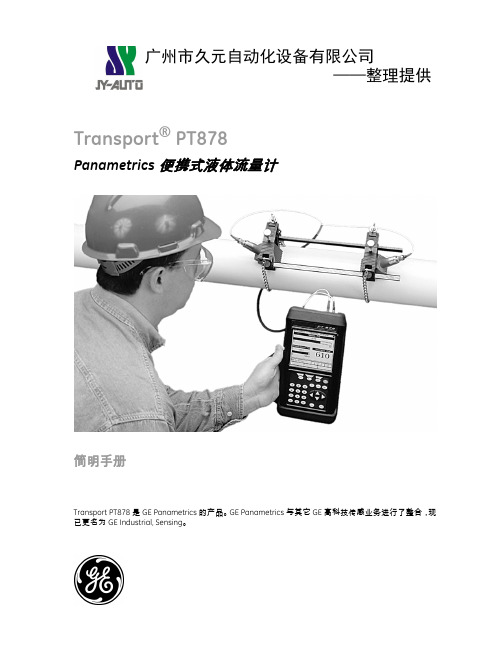
GE Sensing TransPort PT878 Panametrics 肥沃式流量计说明书

GESensingTransPort ®PT878Panametrics PortableUltrasonic Liquid FlowmeterTransPort PT878 is a Panametrics product. Panametrics has joined other GE high-technology sensing businesses under a new name _GE Industrial, Sensing.ApplicationsThe TransPort PT878 portable liquid flowmeter is a complete portable ultrasonic flow metering system for measurement of:•Potable water •Wastewater•Cooling and heating water •Ultrapure water and liquids •Water/glycol solutions •Crude oil•Refined hydrocarbons •Diesel and fuel oils •Lubricating oils •Chemicals •Beverages •Other liquidsgFeatures•Small, lightweight and easy to use •Non-intrusive flow measurement •Velocity, volumetric and energy flow rates •Totalized flow and trend data •Large, backlit LCD display •Alphanumeric and graphic formats •Multiple-language user interface •Rechargeable battery pack •Logs over 100,000 flow data points •Submersible package •32 site locations •Optional thickness gauge •Optional energy measurement•Suitable for most pipe sizes and materials, including lined pipe1981Portable Flow Metering at Its BestThe TransPort PT878 flowmeter is a highly versatile,self-contained, portable transit-time system with options and accessories to meet all your liquid flow measurement needs. Its compact size; lightweight, rechargeable internal battery pack; and universal power supply charger make it the ideal go-anywhere flowmeter.Accurate with Two-Phase and Perfectly Clean LiquidsThe TransPort PT878’s patented CorrelationTransit-Time™ digital signal processing (DSP) technique greatly increases its signal-to-noise ratio for accurate, drift-free flow measurement in liquids that contain a second phase of entrained solids or gas bubbles. The TransPort flowmeter operates in these and other difficult applications where conventional transit-time flowmeters fail.The TransPort PT878 flowmeter also accurately measures flow rate in perfectly clean liquids containing no “scatterers,” where Doppler-type flowmeters cannot work. The TransPort flowmeter is suited for all standard transit-time applications, plus many that would prevent other transit-time flowmeters from working.Quick and Easy to UseIt’s possible to make your first flow measurement within minutes of opening the box—the TransPort flowmeter is that easy to use. Simply input the site parameters, clamp the transducers onto the pipe, adjust the spacing, and you’re under way. No ancillary equipment is needed, and there’s no need to break into the pipeline. An experienced user can make scores of different measurements in a single day. The TransPort PT878 flowmeter is ideal for all kinds of flow survey work.Flow Transducers and Clamping FixturesUsing clamp-on transducers, the TransPort PT878 flowmeter measures flow rate through metal, plastic or even concrete-lined pipes, without penetrating the pipe wall. From ultra-pure water to corrosive and toxic liquids, the TransPort PT878 flowmeter ensuresnon-contaminating, leak-free measurement withdrift-free accuracy. The TransPort PT878 flowmeter has no moving parts to wear or orifices to clog. It can’t be fouled, and it requires no routine maintenance.A wide variety of transducers are available with different operating frequencies, materials of construction, operating temperatures and sizes to meet the requirements of rugged industrial environments.To hold clamp-on transducers in contact with the pipe, a variety of clamping fixtures are available to accommodate different pipe and transducer sizes. These fixtures use a variety of attachment methods including chain, metal strap, Velcro® strap and magnetic clamps. Alphanumeric and Graphic Liquid Crystal Display Completes the PictureA large, multifunction LCD presents measured data in both alphanumeric and graphic forms. In addition, it helps make programming easy by presenting a software menu that walks you through data entry and function selection.Standard alphanumeric functions include flow velocity, volumetric or energy flow rates, and totalized flow in either English (U.S.) or metric units.In graphic mode, the LCD shows both real time and logged data. The result is a chart recording right on the display, which is very useful for reviewing data and observing trends while on the site.Submersible, Rugged Electronics HousingYour investment in this flowmeter is protected from the day-to-day rigors of industrial usage. The TransPortPT878 is equipped with a rubber boot that provides protection against vibration and shock. The completely sealed housing and ports meet IP67 requirements, so the unit will withstand submersion in up to 3 ft (1 m) of water for limited periods of time. It will continue to function safely even if it is dropped in water.The complete TransPort PT878flowmeter system f its in a compact carrying case.Optional Energy MeasurementThe TransPort PT878 flowmeter combines proven ultrasonic flow measurement with precise RTDtemperature measurement to determine the energy flow rate in liquid heating and cooling systems.With this option, the TransPort flowmeter comesequipped with a built-in power supply for loop-powered RTD temperature sensors, as well as all necessary circuitry and software to make energy flow ratemeasurements. GE offers a variety of optional clamp-on and wetted RTD temperature sensors.Optional Pipe Wall Thickness Gauge TransducerPipe wall thickness is a critical parameter used by the TransPort flowmeter for clamp-on flow measurements.The thickness-gauge option allows accurate wall thickness measurement from outside the pipe.Infrared PortThe TransPort PT878 contains an infrared port forcommunication with your PC. If your laptop or desktop PC does not have infrared capability, an adapter isavailable that can be plugged into your PC’s serial port.Optional Infrared Thermal Printer and AccessoriesWhen you need a permanent record of your work, live measurements, logged data and site parameters can be sent to a variety of printers by beaming data directly from the TransPort PT878’s infrared port. A compact,lightweight, hand-held, infrared thermal printer isavailable. This printer is powered by a lithium ion battery.Built to Be Economical and Stay EconomicalTo be of real value, a portable flowmeter must be as economical to own and operate as it is capable in the field. The TransPort PT878 flowmeter is built to stay in service for many years. Completely solid state, the device rarely wears out or needs servicing, resulting in little downtime and low maintenance costs.The TransPort PT878 Flowmeter Uses the Transit-Time Flow Measurement TechniqueIn this method, two transducers serve as both ultrasonic-signal generators and receivers. Whenmounted on a pipe, they are in acoustic communication with each other, meaning that the second transducer can receive ultrasonic signals transmitted by the first transducer and vice versa.In operation, each transducer functions as a transmitter,generating a certain number of acoustic pulses, and then as a receiver for an identical number of pulses.The time interval between transmission and reception of the ultrasonic signals is measured in both directions.When the liquid in the pipe is not flowing, the transit-time downstream equals the transit-time upstream. When the liquid is flowing, the transit-time downstream is less than the transit-time upstream.The difference between the downstream and upstream transit times is proportional to the velocity of the flowing liquid, and its sign indicates the direction of flow.Ultrasonic Signal PathTransit-time flow measurement technique11AC charger2LEMO®-BNC transducer interconnection cable 3Input/output cable4IR-to-serial port adapter 5Small-pipe transducers 6Thickness gauge7Transducers with universal clamping fixture 8IR thermal printer9Printer AC power supply 10Printer battery chargerTransPort PT878 Accessories2345678910PT878SpecificationsFluid TypesAcoustically conductive fluids, including most clean liquids, and many liquids with entrained solids or gas bubbles. Maximum void fraction depends on transducer,interrogation carrier frequency, path length and pipe configuration.Pipe Sizes0.5 in to 300 in (12.7 mm to 7.6 m) and larger Pipe Wall Thickness Up to 3 in (76.2 mm)Pipe MaterialsAll metals and most plastics. Consult GE for concrete,composite materials, and highly corroded or lined pipes.Clamp-On Flow Accuracy (Velocity)•Pipe ID>6 in (150 mm): ±1% to 2% of reading typical •Pipe ID<6 in (150 mm): ±2% to 5% of reading typical Accuracy depends on pipe size and whethermeasurement is one-path or two-path. Accuracy to ±0.5%of reading may be achievable with process calibration.Repeatability±0.1% to 0.3% of reading Range (Bidirectional)–40 to 40 ft/s (–12.2 to 12.2 m/s)Rangeability (Overall)400:1Specif ications assume a fully developed flow prof ile (typically 10 diameters upstream and 5 diameters downstream of straight pipe run) and flow velocity greater than 1 ft/s (0.3 m/s).Measurement ParametersVolumetric flow, totalized flow and flow velocityOperation and PerformanceFlow MeasurementPatented Correlation Transit-Time mode EnclosureSubmersible IP67DimensionsWeight 3 lb (1.36 kg),size (h x w x d) 9.4 in x 5.5 in x 1.5 in (238 mm x 138 mm x 38 mm)Display240 x 200 pixel backlit LCD graphic display Keypad25-key rubberized tactile membrane keypadInternal BatteryRechargeable battery: 9 to 11 hr of continuous operation Battery Charger Input100 to 250 VAC, 50/60 Hz, 0.38 A MemoryFLASH memory, field-upgradable Operating Temperature –4°F to 131°F (–20°C to 55°C)Storage Temperature–40°F to 158°F (–40°C to 70°C)To ensure maximum battery life, storage temperature exceeding 35°C (95°F) is not recommended for more than one month.Standard Inputs/Outputs•One 0/4 to 20 mA current output•One user-selectable pulse (solid state, 5 V maximum) or frequency (5 V square wave, 100 to 10,000 Hz)•Two 4 to 20 mA analog inputs with switchable power supply for loop-powered temperature transmitters Digital InterfaceInfrared communication port for printer or PC interface Site-Parameter Programming•Menu-driven operator interface using keypad and “soft” function keys•Online help functions including pipe tables •Storage for saving site parametersElectronicsPT878 thickness-gauge optionPT878SpecificationsClamp-On Ultrasonic Flow TransducersTemperature Ranges•Standard: –40°F to 300°F (–40°C to 150°C)•Optional (overall range): –310°F to 572°F (–190°C to 300°C)MountingsStainless steel chain or strap, welded or magnetic clamping fixturesArea Classifications•Standard: General purpose•Optional: Weatherproof Type 4/IP65•Optional: Submersible IP67/68PT878 electronics are designed for general purpose areas.Thickness-Gauge OptionTransducerPanametrics dual-element transducer Pipe-Thickness Range0.05 in to 3 in (1.3 mm to 76.2 mm)Pipe MaterialsMost standard metal and plastic pipe materials Accuracy±1% typical or ±0.002 in (±0.05 mm)Thermal ExposureContinuous operation to 100°F (37°C); intermittentoperation to 500°F (260°C) for 10 sec followed by 2 min air coolingTransducer Cables•Standard: One pair of LEMO® coaxial transducer connectors with 25-ft (8-m) cables•Optional: 1,000-ft (305-m) extension cables available for most transducersData Logging•Memory capacity to log over 100,000 flow data points •Keypad programmable for log units, update times, and start and stop timeDisplay Functions•Graphic display shows flow in numerical or graphic format•Displays logged data•Extensive diagnostic parameters•Supports multiple languages: Dutch, English, French, German, Italian, Japanese, Portuguese, Russian, Spanish, Swedish and othersEuropean ComplianceBattery-powered system complies with EMC Directive 89/336/EEC and transducers comply with PED 97/23/EC for DN<25PT878 Specifications Energy MeasurementEnergy MeasurementCalculates energy flow rate and totalized energy. Requires optional dual-RTD, loop-powered transmitter. Temperature TransducersLoop-powered, three-wire platinum RTDs; clamp-on and wetted (thermo-well) types are availableAccuracy±0.15°C with wetted RTDs (matched pairs)Range–4°F to 500°F (–20°C to 260°C)The accuracy of the energy measurement is a combination of the accuracy of the associated flow and temperature measurements. 1% to 2% of reading is typical for calibrated systems. Not all extremes of parameters can be achieved simultaneously.Additional OptionsPanaView™ PC-Interface SoftwareThe TransPort PT878 communicates with a PC through the infrared interface and Windows® operating systems. Consult the manual for details on sites, logs and other operations with a PC.Printer•Infrared, portable, thermal printer with rechargeable battery and 120 to 240 VAC power supply/recharger •Weight 13 oz (370 g), size 6.3 in x 6.5 in x 2.3 in (160 x mm 164.2 mm x 59 mm), print width 4 in (104 mm)RS232-to-InfraredInfrared adapter plugs into any available serial port to give desktop PCs infrared capability.PanaView software links your TransPort flowmeter to your PC.©2005 GE. All rights reserved.920-039BAll specifications are subject to change for product improvement without notice. TransPort®is a registered trademark of GE. Correlation Transit-Time™ is a trademark of GE. GE®is a registered trademark of General Electric Co. Other company or product names mentioned in this document may be trademarks or registered trademarks of their respective companies, which are not affiliated with GE.g 。
超声波流量计方案

超声波流量计方案引言超声波流量计是一种常用的流量测量设备,它利用超声波技术来测量液体、气体以及蒸汽等流体的流量。
本文将介绍超声波流量计的工作原理、应用场景以及选型时的一些建议。
工作原理超声波流量计利用超声波在介质中的传播速度与介质流速之间的关系来测量流量。
它通过发射一束超声波,并利用接收器接收超声波的反射信号来计算流速。
超声波在介质中的传播速度受到介质密度、温度和流速的影响。
通常情况下,流体的密度和温度变化较小,因此主要通过测量超声波传播时间来计算流速。
超声波流量计通常包括一个发射器和一个或多个接收器。
发射器和接收器之间的距离确定了测量路径。
当超声波经过流体时,它的传播速度会受到流体流速的影响。
接收器接收到反射的超声波信号,并将其传递给测量设备。
通过测量超声波的传播时间和路径长度,可以计算出流体的流速。
应用场景超声波流量计在许多领域都有广泛的应用,特别是在工业自动化领域中。
以下是一些常见的应用场景:1.液体流量测量:超声波流量计可用于测量液体流量,例如供水管道、化工流程、石油和天然气管道等。
2.气体流量测量:超声波流量计也可用于测量气体流量,例如空调系统、天然气和石油气流动等。
3.蒸汽流量测量:超声波流量计在蒸汽系统中也有广泛的应用,可用于测量蒸汽的流量和质量。
由于超声波流量计具有非接触式、无压力损失、广泛测量范围和高精度等优点,因此被广泛应用于液体、气体和蒸汽的流量测量。
选型建议在选择超声波流量计时,需要考虑以下因素:1.测量介质:不同的超声波流量计适用于不同的介质,例如液体、气体或蒸汽。
确保选购的超声波流量计适用于要测量的介质。
2.测量范围:不同的超声波流量计有不同的测量范围。
根据实际需求选择合适的测量范围。
3.精度要求:超声波流量计的精度常常是选择的关键因素。
根据应用需求选择适当的精度。
4.环境条件:考虑超声波流量计将使用的环境条件,例如温度、压力和湿度。
选择适应环境条件的超声波流量计。
5.信号输出:超声波流量计的信号输出方式也是一个重要的考虑因素。
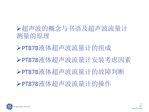
PT878便携式超声波中文操作手册(修改)
PT878-PT878GC

1
GE Infrastructure Sensing
超声波流量计原理:时差法
流体流速V
传感器既发送信号又接收 信号 逆流方向传输时间 tup, 超声波被流体减速 顺流方向传输时间 tdn, 超声波被流体加速
2
tup tdn
V
tup =
tdn =
P c -Vsin q P c +Vsin q
12
GE Infrastructure Sensing
全新的手持式流量计PT878
图形用户界面(GUI),简单、明了
易于使用
标签式设定窗口使设置易如反掌,
将相关信息集中,所有的可选项同 时显示
13
GE Infrastructure Sensing
全新的手持式流量计PT878
具备红外通讯功能,无需杂乱的电缆
全新的手持式流量计PT878
为恶劣的工业操作条件设计,不受地域限
制, 潜水型,防护等级IP67
小巧轻便 (238×138×38 mm,1.36 kg),
易于携带
超大液晶显示屏,分块显示屏可显示 1到4个
参数,支持多种语言
超强的数据存储能力,可方便地记录超过
100,000点以上的数据
颜色
红 棕
H
高温, -20 oC ~ +210 oC
绿
防爆等级: EEX md IIC T6
可提供防水接头 (U)
8
GE Infrastructure Sensing
液体测量系统: 夹装式传感器
OKS
所测管径从 3” ~ 24”
测量温度
• -200至360度
超声波液体流量计简明使用手册

Panametrics公司TransPort®PT878手持式超声波液体流量计简明使用手册概述1.以Panametrics公司提供的TransPort®PT878英文手册为准,中文简明手册仅供参考。
2.超声波时差法流量计通过使用一对传感器,每个传感器通过流体发射和接收超声波信号。
当流体流动时,顺流方向信号的传播时间短于逆流方向,这个时间差正比于流体流速。
TransPort®PT878流量计测量这个时间差,结合设置的管径参数来计算流体的流速。
3.TransPort®PT878采用管外夹装式传感器,安装简便,无需破管与接触介质。
4.TransPort®PT878采用了受专利保护的声信号编码技术,从而极大提高了信噪比,这使得TransPort®PT878不仅适用于绝大多数的纯净液体应用,也为众多包含气泡、液滴或夹带固体颗粒等传统时差法原理无法测量的两相流体提供精确、无漂的测量。
PT878新特点♦可方便地按照您想看的格式显示您想看的数据∙超大液晶显示屏▫电致背景发光▫分块显示屏可显示1到4个参数∙支持多种语言♦为恶劣的工业操作条件设计,不受地域限制∙潜水型,防护等级IP67∙配有橡胶护罩和内置支架,可保护仪表电子部分♦可方便地记录超过100,000点以上的数据,无需杂乱的电缆就可将其下载至您的PC机∙红外通讯♦易于设置与操作∙可调的手带,携带方便∙下拉式菜单与软式按键让设置瞬间完成♦FLASH闪存∙不需更换EPROMs就可通过红外通讯口升级PT878的软件程序传感器安装和测量管路要求1.考虑到管路中流体可能存在的固体颗粒和气泡的分布,传感器应水平安装。
2.管路内流体需满管。
3.选择测量管路时应该避免选用流体自上向下流动的竖直管线。
4.传感器安装位置应远离弯头,变径,阀门,节流装置,安装点直管段的要求至少要满足前10D后5D(D为管线直径)。
5.为保证超声波发射和接收稳定,管线表面应该平整光滑,传感器表面和管径接触部不允许含有空气,必须涂抹耦合剂。
PT超声波流量计原理与安装
11 / GE / January 27, 2019
介质要求
1.已列出的介质直接选择 2.未列出的介质需输入声速或选择跟踪窗口测 试 3.确定声速的目的是在窗口中央将信号检出..
WINDOW
END OF TRANSMIT GOOD SNR
12 / GE / January 27, 2019
1.根据管道大小和信号强度选择安装方式 A.单声程:大管道和复杂应用 B:双声程:首选方式,安装简单. C:多声程:小管道,信号特强. 安装位置:水平管道 3点和9点位置 垂直管道必须是介质向上流
超声波流量计原理:时差法
传感器既发送信号又接收 信号
tup tdn
V
声信号传播时间
逆流传播, tup 顺流传播, t dn
tup =
tdn =
tup = 超声波被流体减速
P c - Vsin q P c +Vsin q
V
q
P L
tdn = 超声波被流体加速
tup > tdn D t = tup - tdn
发射角度
传播时间
42
17.3
42
20.3
35
27.5
59.5
5.85
传播速度
使用温度
2484
-40 to 150 C
2484
-40 to 150 C
2674.6
-20 to 210C
3328
-40 to 230C -200 to 360 C
9/ GE / January 27, 2019
传感器选用原则
声波 20 Hz to 20 kHz (Human hearing) 超声波 >20 kHz
PT878中文安装指南
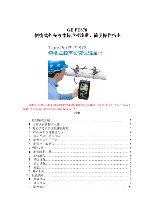
GE PT878便携式外夹液体超声波流量计简明操作指南本指南主要写明了测量的主要步骤和相关注意事项,涉及具体的仪表中设置与操作的菜单部分请参考原User Manual !目录一、基础知识介绍 (2)1. 检查仪表及相关组件 (2)2. 时差法超声波流量测量原理 (3)3、探头频率及可测量范围 (4)4、探头及其它外部接口 (4)5、测厚探头使用示意 (5)6、测量点一般要求 (6)二、测量安装 (6)1、测量辅助工具 (6)2、安装准备 (6)3、参数设置 (6)4、显示设置 (6)5、安装 (6)6. 开始测量 (9)三、设置菜单 (10)1、参数设置 (10)2、显示设置 (17)3、测厚方法 (20)一、基础知识介绍1. 检查仪表及相关组件仪表组件一般包含以下部分:仪表、充电器、探头、电缆、夹具、耦合剂、测厚仪(可选),组件形状参照下图(具体组件个数应参照订单,图中组件许多是可选项)2. 时差法超声波流量测量原理顺流信号传播时间短于逆流方向,这个时间差正比于流体流速一般可采用单声程安装方式(如下第一个图,适于大管径,信号强度较高)或双声程安装方式(如下第二个图,适于较小管径,安装比较容易,上下游探头比较容易保证在一条水平线上)3、探头频率及可测量范围探头频率一般有三种:500KHZ、1MHZ、2MHZ、4MHZ。
基本规律是频率越低测探头频率一般有三种量管径越大。
4MHZ测量范围为:1/2’’到2’’,主要有UTXDR-408(常温:-20 to 120 C)2MHZ测量范围为:2’’到8’’,主要有UTXDR-407(常温:-20 to 120 C),C-RS-403(中温:-40 to 150 C),C-PT-117(高温:-20 to 210 C)1MHZ测量范围为:2’’到300’’,主要有C-RS-402(中温:-40 to 150 C),C-PT-116(高温:-20 to 210 C)0.5MHZ测量范围为:2’’到300’’,主要有C-RS-401(中温:-40 to 150 C),C-PT-115(高温:-20 to 210 C)4、探头及其它外部接口5、测厚探头使用示意具体菜单请参考 User Manual和后面的指南。
PT878液体流量计

PT878液体流量计作业指引1.0目的本文的目的是为PT878超声波液体流量计操作提供指导,从而使操作规范化。
2.0适用范围PT878超声波液体流量计适用于测量导声单向流体流量,可测流速范围为±0.03~~±12m/s 3.0设备工具主机、传感器、信号线、红外线RS232、测厚探头、偶合剂、卷尺、测温仪、砂纸4.0操作内容4.1测量管径4.1.1如果能从PI&D图和得到管子的型号并查出管子的尺寸、材质、管壁厚及是否有衬里等参数就可以跳过这一步,直接进入PT878的进行管子参数的设置。
4.1.2如果没有管子的参数,就要通过以下的方法的测量:4.1.2.1 测量管径。
(测试五点取均值)4.2测量管厚4.2.1校验测厚仪4.2.1.1将右边测厚探头与左边的标定器涂上足够的耦合剂,把测壁厚探头按在管壁上,尽量保持不动。
4.2.1.2校验路径:Menu/service/Display T-Gauge/Zero/Calibrate4.2.2测量壁厚4.2.2.1把管壁的油漆和油脂除去,并擦干净被区域。
接好测壁厚探头,开机,按路径进去,在探头和被测管壁上涂上足够的耦合剂,把测壁厚探头按在管壁上,尽量保持不动。
在pt878上读出管壁厚度。
(测八点取均值)路径:Menu/Service/T-Gauge Display 或者:Menu/Program/Pipe/Measure with T-Gauge4.3测量管壁温度4.3.1用测温仪测试管壁温度4.4设置参数4.4.1开启仪器(按住那个红色的键)4.4.2设置探头型号4.4.2.1确定你准备使用的Transducer型号,然后在878中输入。
路径:Menu/Program/Transducer.4.4.2.2设置管壁温度(Wedge Tmp)将光标移至Wedge Tmp,输入管壁的温度。
设置好后按F3(默认的温度是20摄氏度/68华氏度)。
PT878便携式超声波液体流量计

开机注意事项
在TransPortPT878工作时不可带电插拔传感器接头 TransPortPT878上电前应插好传感器或测厚传感器,以 使内部的自动增益控制功能更好地发挥功效 每次连接传感器与TransPortPT878前应将传感器内储存 静电放除
显示屏描述
测量数据 当前测点 状态栏 电池状态
DEFAULT
测量显示
TransPortPT878显示屏幕最多能同时显示4个测量参数,开机后按MENU 键,选择Site子菜单后按ENTER键在出现的下拉式菜单中用▲和▼键选 定屏幕所要显示的参数量,如1View代表显示1个参数,2View代表显示 2个参数,以此类推。 TransPortPT878还可将屏幕上现有的参数改变成想要显示的其它参数。 如想用累积流量参数来替代体积流量参数值显示,可重复按SEL键将► 光标移至体积流量参数值,然后按ENTER键在出现的目录中用►键选定 Measurement后按ENTER键,出现Change后再按ENTER键,在下拉式测量 参数菜单中用▲和▼键选定Fwd Totalizer项按SEL键选定,然后在右 半显示框中选择累积流量单位(如m3)后按F3键确认。在屏幕上原显示 体积流量参数值已改变成累积流量值。其它测量参数改变以此类推。
SEL光标键 —— 用于切换显示屏上测量数 值位置 ESC退出键 ——用于随时退出菜单或菜单 选择;取消数字输入 红色键 —— 用于开启和关闭电源及背景光。
开启和关闭电源
必须插上电源或电池必须先充上电才能操作 TransPort PT878。按下位于键盘右上角的红色电源键, 打开TransPort PT878。仪器将会执行以下的自我检验 并显示它们的状态。
其下的Reynolds Correction为雷诺数修正,选择开启雷 诺数修正(Re Correction On)并输入流体粘度 m2/S来进行流场修正。
超声波流量计测量方法

超声波流量计流量测量方法
参数【50】---显示信号强度,一般必须>60%,右下角有字母跳动表示是假信号,不可取
在参数【50】显示线,按向上的键显示实时的流量,累计流量【16】--加持方式 V方式同一侧上下一条线
Z方式两侧对立上下一条线
方法:选择好管径,壁厚,材质等参数,选择加持方式Z方式,自动计算出两超声波传感器质检的距离
注1:前十后五:安装位置在阀门以外的十倍管径距离开始,最好露出五倍管径距离方便安装,防止干扰
例如:管径80,安装位置最好在阀门以外800处开始,有80*5=400的安装空间
注2:测量的时候必须是满管的状态,也就是说管内无气泡无杂质,远离电机,变频器,阀门等干扰项目
1。
电子测量仪之超声波流量计的安装和检测方法 流量计如何操作
电子测量仪之超声波流量计的安装和检测方法流量计如何操作目前通常接受两种类型的超声波流量计,一种为多普勒超声波流量计,另一类为时差式超声波流量计。
多普勒型是利用相位差法测量流速,即某一已知频率的声波在流体中运动,由于液体本身有一运动速度,导致超声波在两目前通常接受两种类型的超声波流量计,一种为多普勒超声波流量计,另一类为时差式超声波流量计。
多普勒型是利用相位差法测量流速,即某一已知频率的声波在流体中运动,由于液体本身有一运动速度,导致超声波在两接收器(或发射器)之间的频率或相位发生相对变化,通过测量这一相对变化就可获得液体速度;时差型是利用时间差法测量流速,即某一速度的声波由于流体流动而使得其在两接收器(或发射器)之间传播时间发生变化,通过测量这一相对变化就可获得流体流速。
目前接受了时差式超声波流量计。
超声波流量计目前通常接受三种安装方式:W型,V型,Z型。
依据不同的管径和流体特性来选择安装方式,通常W型适用于小管径(25~75mm),V型适用于中管径(25~250mm),Z型适用于大管径(250mm以上),总之,为了提高测量的精准性和灵敏度,选择合适的安装方式,使得测量信号(即差值)与二次仪表相匹配。
目前我用了Z型安装。
为了保证仪表的测量精准度,应选择充分确定条件的场所定位:通常选择上游10D、下游5D以上直管段;上游30D内不能装泵、阀等扰动设备。
(1)零流量的检查当管道液体静止,而且四周无强磁场干扰、无猛烈震动的情况下,表头显示为零,此时自动设置零点,除去零点飘移,运行时须做小信号切除,通常可流量小于满程流量的5%,自动切除。
同时零点也可通过菜单进行调整。
(2)仪表面板键盘操作启动仪表运行前,首先要对参数进行有效设置,例如,使用单位制、安装方式、管道直径、管道壁厚、管道材料、管道粗糙度、流体类型、两探头间距、流速单位、最小速度、最大速度等。
只有全部参数输入正确,仪表方可正确显示实际流量值(3)流量计的定期校验为了保证流量计的精准度,我们进行定期的校验,通常我们接受更高精度的便携式流量计进行直接对比,利用所测数据进行计算:误差=(测量值—标准值)/标准值,利用计算的相对误差,修正系数,使得测量误差充分±2%的误差,即可充分计量要求。
超声波流量计的测量原理介绍 流量计工作原理

超声波流量计的测量原理介绍流量计工作原理超声波流量计是一种耐用的、非接触式测量污水的超声波流量计,便携式多普勒超声波流量计紧要应用于城市污水处理厂、排水泵站环保检测及矿山、油田、冶金、化工、炼油、造纸、食品等行业的循环水、纸浆、矿浆、泥浆、酸碱液、化学原材料、海水、城市排水、工业废水、生活污水、油水混合液等流量计量。
测量原理便携式超声波流量计探头随仪表成对供应,实流标定后出厂。
全部标定数据、零偏及探头参数全部储存在探头内存里,与主机连接后,探头将数据发送给主机,主机会自动识别并优化工作。
便携式超声波流量计匹配所连接的探头后,用户只需输入管道和介质参数即可。
同时,仪表内置的数据库供应了大多数常用管材和介质的选项,测量时,用户还可依据状态显示了解应用情况。
全密封探头及一体式电缆确保长期牢靠的工作,探头及电缆铠装层均为不锈钢材质,适用于苛刻的工业环境。
便携式超声波流量计接受独特的双uP技术,高速采样和自适应信号处理技术,即使在苛刻的测量工况下,也能牢靠而稳定的工作。
应用指南便携式超声波流量计在石油化工行业、核电行业、导热油领域有着独特的应用,并且接受了能量计算功能,可以在测量流量的同时,引入温度信号,从而取得能量参数。
旋进旋涡气体流量计表头故障解决方法旋进旋涡气体流量计接受较新微处理技术,具有功能强、流量范围宽、操作维护和修理简单,安装使用便利等优点,紧要技术指标达到国外同类产品先进水平。
广泛应用于石油、化工、电力、冶金煤炭等行业各种气体计量。
一、旋进漩涡流量计表头显示瞬时流量、压力正常,温度显示与工作现场温度不符1.温度示值为“—75C”或超过“100℃”。
温度传感器损坏。
可更换传感器。
2.温度示值超过或低于现场实际温度,更换传感器后,仍为该现象。
温压电路损坏。
可更换温压电路。
二、旋进漩涡流量计表头无显示1.流量计无24V电源或电池供电。
对流量计进行24V供电或更换流量计电池。
2.流量计液晶板损坏。
PT878超声波流量计流量监测方案
PT878超声波流量计流量监测⽅案超声波流量计监测⽅案编制:校核:审核:审定:⽇期:2010年4⽉27⽇液体超声波流量计流量测量⽅案⼀、总则为了便于计算压缩机、风机、泵等的功率,特使⽤此监测⽅案,对进出⼝各种⽓体及液体进⾏流量监测。
⼆、液体的流量测量条件如果泵进出⼝为液体,使⽤便携式超声波流量计(型号为PT878)进⾏流量测量,测量钱对管道及其他条件的基本要求:1、测量点的选取,管道表⾯必须光滑⽆防腐漆及保温棉,便于检测器探头与管道良好的接触,2、测量点前后管道的要求,必须遵守前10后5的原则,在此直径长度⽆弯头、阀门等引起流体扰动的装置,⽽且要在满管的情况下测量,保证测量的准确度。
3、测量过程中,要保证泵运⾏状态稳定,⽽且是系统负荷稳定的状态下。
4、位置选取好,根据超声波流量计的安装要求进⾏测量探头、电缆的安装,及测量仪表的组态。
5、根据⼯艺⼈员提供的管道、液体各项参数进⾏流量测量。
6、每种⼯况测试过程时间不少于1h。
同⼀⼯况点应间隔重复测量三次,每次测量间隔10到15 min。
以三次测量的平均值作为测算泵系统电能平衡和系统运⾏效率值。
三、超声波流量计参数设置1、此流量计安装⽅式为夹套式,探头需要与管道密切接触,安装固定好,使⽤信号线于主机进⾏连接。
2、对主机的参数进⾏设置。
3、开机显⽰此画⾯为主画⾯,有以下4个显⽰部分。
4、在Program 选项上选择Transducer,如下图:5、在第四步的基础上进⼊如下菜单,设置传感器的安装⽅式为第⼆种(Clamp-on)夹套式,传感器的编号,在传感器上有标识。
传感器的安装位置如下:⽔平管道在3点和9点位置,在同⼀侧或是在对侧,垂直管道要求必须液体从下往上流。
对侧位置安装俯视图同侧位置安装俯视图6、进⼊PIPE管道参数设置,选择管道的材质,设置管道的直径、周长、壁厚,然后按ENTER确认。
7、进⼊LINING参数设置,设置管道有⽆内衬以及内衬的厚度,传播声⾳的速度。
- 1、下载文档前请自行甄别文档内容的完整性,平台不提供额外的编辑、内容补充、找答案等附加服务。
- 2、"仅部分预览"的文档,不可在线预览部分如存在完整性等问题,可反馈申请退款(可完整预览的文档不适用该条件!)。
- 3、如文档侵犯您的权益,请联系客服反馈,我们会尽快为您处理(人工客服工作时间:9:00-18:30)。
超声波流量计监测方案
编制:
校核:
审核:
审定:
日期:2010年4月27日
液体超声波流量计流量测量方案
一、总则
为了便于计算压缩机、风机、泵等的功率,特使用此监测方案,对进出口各种气体及液体进行流量监测。
二、液体的流量测量条件
如果泵进出口为液体,使用便携式超声波流量计(型号为PT878)进行流量测量,
测量钱对管道及其他条件的基本要求:
1、测量点的选取,管道表面必须光滑无防腐漆及保温棉,便于检测器探头与
管道良好的接触,
2、测量点前后管道的要求,必须遵守前10后5的原则,在此直径长度无弯
头、阀门等引起流体扰动的装置,而且要在满管的情况下测量,保证测量的准确度。
3、测量过程中,要保证泵运行状态稳定,而且是系统负荷稳定的状态下。
4、位置选取好,根据超声波流量计的安装要求进行测量探头、电缆的安装,
及测量仪表的组态。
5、根据工艺人员提供的管道、液体各项参数进行流量测量。
6、每种工况测试过程时间不少于1h。
同一工况点应间隔重复测量三次,每
次测量间隔10到15 min。
以三次测量的平均值作为测算泵系统电能平衡和系统运行效率值。
三、超声波流量计参数设置
1、此流量计安装方式为夹套式,探头需要与管道密切接触,安装固定好,使
用信号线于主机进行连接。
2、对主机的参数进行设置。
3、开机显示此画面为主画面,有以下4个显示部分。
4、在Program 选项上选择Transducer,如下图:
5、在第四步的基础上进入如下菜单,设置传感器的安装方式为第二种
(Clamp-on)夹套式,传感器的编号,在传感器上有标识。
传感器的安装位置如下:水平管道在3点和9点位置,在同一侧或是在对侧,
垂直管道要求必须液体从下往上流。
对侧位置安装俯视图
同侧位置安装俯视图
6、进入PIPE管道参数设置,选择管道的材质,设置管道的直径、周长、壁
厚,然后按ENTER确认。
7、进入LINING参数设置,设置管道有无内衬以及内衬的厚度,传播声音的
速度。
8、进入Fluid参数设置,第一个Tracking Windows选择NO,流体类型,测
量某种介质参数设置成该液体的参数
9、进入PATH参数设置,前面两项不需设置,要设置声程数Traverses,传
感器间距。
10、所有参数设置完成,要按ENTER回车键,进行确认,按F3键回到测
量画面。
11、测量完数据进行记录,进行拆除测量探头,管道及其他设备进行复位。
气体超声波流量计流量测量方案
由于超声波的类型相似,液体的测量条件及参数设置的前十步一样,由于气体受压力、温度的影响比较大,还要在原有的参数设置基础上,设置压力、温度参数。
压力及温度的参数设置:
1、在Program 选项上选择Std Vol/Mass Flow,如下图:
2、进入如下画面:在Settings菜单里设置Standard_V olume参数,为Enabled,设置基本压力、大气压及基本温度的参数。
3、进入下个Inputs菜单设置,设置压力、温度的参数是稳定的还是活动的,
以及压力、温度的值。
4、进入Mass Flow菜单设置,设置Mass Flow为可用,设置累积量计算方法
为静态密度,设置饱和蒸汽输入方式为压力或温度,设置静态密度值。
其他操作步骤与液体超声波流量计一样。
