YYC 超声波流量计说明书
超声波明渠流量计说明书
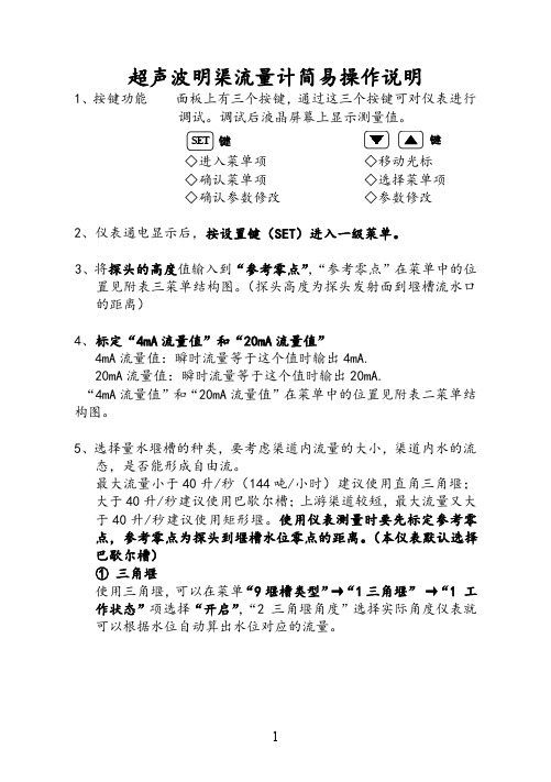
超声波明渠流量计简易操作说明1、按键功能面板上有三个按键,通过这三个按键可对仪表进行调试。
调试后液晶屏幕上显示测量值。
SET键键◇进入菜单项◇移动光标◇确认菜单项◇选择菜单项◇确认参数修改◇参数修改2、仪表通电显示后,按设置键(SET)进入一级菜单。
3、将探头的高度值输入到“参考零点”,“参考零点”在菜单中的位置见附表三菜单结构图。
(探头高度为探头发射面到堰槽流水口的距离)4、标定“4mA流量值”和“20mA流量值”4mA流量值:瞬时流量等于这个值时输出4mA.20mA流量值:瞬时流量等于这个值时输出20mA.“4mA流量值”和“20mA流量值”在菜单中的位置见附表二菜单结构图。
5、选择量水堰槽的种类,要考虑渠道内流量的大小,渠道内水的流态,是否能形成自由流。
最大流量小于40升/秒(144吨/小时)建议使用直角三角堰;大于40升/秒建议使用巴歇尔槽;上游渠道较短,最大流量又大于40升/秒建议使用矩形堰。
使用仪表测量时要先标定参考零点,参考零点为探头到堰槽水位零点的距离。
(本仪表默认选择巴歇尔槽)①三角堰使用三角堰,可以在菜单“9堰槽类型”→“1三角堰”→“1工作状态”项选择“开启”,“2三角堰角度”选择实际角度仪表就可以根据水位自动算出水位对应的流量。
②矩形堰使用矩形堰,可以在菜单“9堰槽类型”→“2矩形堰”→“1工作状态”项选择“开启”,并且在“2标准渠道”中选择“0.25米、0.50米、0.75米、1.00米、非标渠道”,仪表就可以根据水位自动算出水位对应的流量。
③梯形堰使用梯形堰,可以在菜单“9堰槽类型”→“3梯形堰”→“1工作状态”项选择“开启”,并且在“2堰槛宽B”中输入实际实际渠道的堰槛宽,仪表就可以根据水位自动算出水位对应的流量。
④巴歇尔槽使用巴歇尔槽,可以在菜单“9堰槽类型”→“4巴歇尔槽”→“1工作状态”项选择“开启”,巴歇尔槽流量公式:Q=Cha n。
根据喉道宽“b”,从“附表二巴歇尔槽水位-流量公式”中查出修工系数c和指数n,输入到菜单“9堰槽类型”→“4巴歇尔槽”→“2修工系数c”和“3指数n”。
超声波流量计操作说明

超声波明渠流量计
一、产品简介
明渠流量计积算仪是一款通用工业智能仪表,具有工业通用 4-20mA,0-20mA,1-5V,0-5V 等线性信号输入方式,及 RS485 串口输入功能(可选)。本仪表集成两路信号输入控制模块,可同 时分别控制每路信号,也可以对两路做相关运算,并显示和输出结果。配合本公司的超声波液位 计使用,可组成液位差控制系统。本仪表集成明渠流量积算仪功能,可作为明渠流量计使用。创 新数据源设计,使应用更具灵活性。
0~13
48
第 2 行显示 第 2 行显示数据源(表 5-1)
0~13
本文作者: 深圳得加利水处理科技有限公司
超声波明渠流量计
49
第 3 行显示 第 3 行显示数据源(表 5-1)
50
第 4 行显示 第 4 行显示数据源(表 5-1)
51
省电模式 0 常开,1 白天,2 无按键(关背光)
52
菜单密码 进入菜单的密码
43
IN 数学运算 数学运算公式(表 8-1)
0~9999999
44
时间设置 系统时间设置
0
45
时钟调速 时钟调速(间隔多少秒增或减一秒)
-9999999~9999999
46
自动打印 自动打印时间间隔分钟数(0 为不自动打印) 0~9999999
47
第 1 行显示 第 1 行显示数据源(表 5-1)
菜单翻页,长按退出菜单
菜
进入菜单项
单
列
表
下翻页
上翻页
确认输入 数 字
移位 输 入
加数 状 态
减数
断电后,按住 通电还原出厂设置。数字加数顺序是从 0~9 . - 循环, 减数相反。 本机菜单分为输入菜单、输出菜单、流量菜单、系统设置、历史数据五组。详见下表:
eyc-tech DPM04流量计总计器用户手册说明书

Manuals+— User Manuals Simplified.eyc-tech DPM04 Flow Totalizer User ManualHome » eyc-tech » eyc-tech DPM04 Flow Totalizer User Manualeyc-tech DPM04 Flow TotalizerContents1 Security Considerations2 Dimension3 Connection4 Installation5 Configuration Software5.1 Application ProgramIntroduction5.2 Establish RS-485 connection5.3 Scan RS-485 connection5.4 Setting RS-485 ModBus Protocol5.5 Measurement Programming5.6 Linearity Computation5.7 Export and Import Configuration5.8 Device Information5.9 Totalizer5.10 Display and Data Log6 Menu Operation6.1 Menu Flowchart7 Inspection And Maintenance7.1 Maintenance7.2 Troubleshooting8 Customer Support9 Documents / Resources9.1 References10 Related PostsSecurity ConsiderationsPlease read this Specification carefully, prior to use of this, and keep the manual properly,for timely reference.Solemn StatementThis product can not be used for any explosion-proof area.Do not use this product in a situation where human life may be affected.eyc-tech will not bear any responsibility for the results produced by the operatorsWarning!Installation and wiring must be performed by qualified personnel in accordance with all applicable safety standards.This product must be operated under the operating conditions specified in manual to prevent equipment damages.Please using the product under the ordinary pressure, or it will influence safe problem.This product must be operated under the operating condition specified in this manual to prevent equipment damages.This product must be operated under the normally atmospheric condition to prevent equipment damages.To prevent products damage, always disconnect the power supply from the product before performing any wiring and installation.All wiring must comply with local codes of indoor wiring and electrical installation rules.Please use crimp type terminal.To prevent personal injury, do not touch the moving part of product in operation.Installation Dimension InstallationConfiguration SoftwareApplication Program IntroductionUser may download the configuration software on eyc-tech web site. Please decompress the application prior to execute it. Operating System requirements:above Windows 7 SP1. Other application program requirements: above Microsoft Office 2003. Hardware requirements: USB to RS-485 converter.Establish RS-485 connection1. Connect product to PC via RS-485 converter2. Execute configuration software3. Click “Interface > Config”4. Select the corresponding values of com port as following :a. Port: Please confirm the connection com port firstb. Baud Rate (DPM04 default 9600)c. Data Frame (device default None Parity Check, 8 data bits, 1 stop bit)d. Response Timeout (default 300ms)e. Retry, trial cycles if communication error (default 2 times)f. Station ID (default 1)5. Click “Apply”6. Connect successfullya. Show value and trend chart of the measurementb. Show value and tread chart of device mcu temperaturec. Show “Open Port, Read successful”Scan RS-485 connection※Use scan function to connect when forgetting the connection information or having more facilities.1. Connect the product to PC via RS-485 converter2. Execute configuration software3. Click “Interface > Config”4. Select the corresponding values of com port as fallowing5. Click “Scan” to execute connection facilities6. Scan connection facilities and set upa. Select Station IDb. Click “CLOSE AND EXPORT”7. Click “Apply”8. Connect successfullya. Show value and trend chart of the measurementb. Show value and tread chart of device mcu temperaturec. Show “Open Port, Read successfulSetting RS-485 ModBus Protocol1. Setting RS-485 connection as step 5.12. Click “Setting” tab3. Select Modbus Protocol parametera. Station ID 1~247b. Baud Rate 9600, 19200, 38400, 57600, 115200c. Data Frame None-8Bit-1Stop, None-8Bit-2Stop, Even-8Bit-1Stop,Even-8Bit-2Stop, Odd-8Bit-1Stop, Odd-8Bit-1StopMeasurement ProgrammingClick the “Configuration” tab, the configuration divide by 4 sub groups as following.1. 1. Input function, this function could be found in “Input” taba. Input type, current, voltage, frequency, pulse or modbusb. Number of input rate decimal places, up to 4c. Low point of input spand. High point of input spane. volume unit of input ratef. period unit of input rateg. Analog input range (valid when the input selects current)h. Analog input range (valid when the input selects voltage)i. Low point of frequency input (valid when the input selects frequency)j. High point of frequency input (valid when the input selects frequency)k. value of pulse input (valid when the input selects pulse)l. unit of pulse input (valid when the input selects pulse) The following input is valid when 485 is selected m. Modbus protocol type, master or slavern. station IDo. Baud rate (valid when the input selects the master node)p. Parity checkq. Stop bitr. Register addresss. Register data typet. Data format, data word high and low exchangeu. Numerical magnificationThe flow totalizer setting itemsv. Number of decimal placesw. volume unitx. duct profile area (valid when velocity to volume conversion)y. flow coefficient (valid when velocity to volume conversion)2. Output function, this function could be found in “Output” taba. output type, current or voltageb. analog output range (valid when the output selects current)c. analog output range (valid when the output selects voltage)d. low point of output spane. high point of output spanf. error reaction, force current output if error detected. Select None if function disable. (valid when the outputselects current)g. linear correction, Off if disable, Interpolation if linear interpolation, Square Root if root extractionh. output cut-off, disable if set 0i. response time, e.g. set 3.0 if take 3.0 seconds for rise time T903. Relay function, this function could be found in “Relay” taba. driven signal source, rate or totalizerb. set pointc. action mode, HI.AL if upscale active, LO.AL if downscale actived. hysteresise. alarm, NONE if disable, HOLD if memory and hold the first alarm until reboot, Action if active when alarmassert, Deaction if inactive when alarm assertf. relay on delay time (seconds)g. relay off delay time (seconds)4. The other items could be found in “Option” taba. LED brightness, 0 darkest, 9 brightestb. password validation, NO if disable, YES is enablec. new passwordd. pause counter of volume accumulatione. reset factory default (without counter of totalizer)Linearity ComputationClick the Interpolation tab to specify the linear interpolation pointsa. interpolation tableb. interpolation curvec. Interpolate input column, device measured value (raw value)d. Interpolate output column, device output value (standard value or correction value)e. Read the interpolation table of the devicef. Clear the interpolation table on configuration software. Note: this action will not modify the interpolation table of the deviceg. apply, the interpolation would be written in deviceExport and Import ConfigurationClick the Setting tab to export and import device configurationa. summary text of device configurationb. read device configurationc. write device configurationd. load device configuratione. save device configurationexport procedure: device connection → step b→ step eimport procedure: device connection→ step d → step cDevice InformationClick the Information tab to get device informationa. device serial numberb. device model namec. firmware versiond. factory mode enabled statee. firmware checksumf. RS-485 enabled stateg. input function enabled stateh. output function enabled statei. totalizer enabled state input calibration information j. analog current input calibration pointsk. analog voltage input calibration pointsl. frequency input calibration pointsOutput calibration informationm. analog voltage output calibration pointsn. analog current output calibration pointso. Calibration dateTotalizerClick the Totalizer tab to display the volumetric accumulation and related functiona. instantaneous flow rate, programmable unitb. instantaneous flow rate, unit of Liter/minc. accumulative flow, unit conversion 1, default m3d. accumulative flow, unit conversion 2, default Litere. unit of accumulative flow 1f. unit of accumulative flow 2g. master enable of volumetric accumulationh. enable of accumulation 1i. enable of accumulation 2j. reset button of accumulation 1k. reset button of accumulation 2Display and Data LogClick the Display tab to display the measurement data and start data log function1. data display: click the “Display” tab2. button descriptionclear the plot charttoggle chart plotting line styleselect the OUTPUT channel you want to setset the line color of the selected OUTPUT channelsnap the currently chart plotexport data log since device is connectedaxis Y main coordinate, ON or OFFaxis X coordinate, ON or OFFaxis Y secondary coordinate, ON or OFFlegend, ON or OFFmeasurement data logging, ON or OFFaxis X time scaleaxis Y amplitude scale3. Set the logging time intervala. Click File > Log Intervalb. select the logging interval4. Store/log measurement datastore measurement data: save the logging data since device is connected click Display > Exportspecify the path and filename > SaveNote: If the specified path and file name are the same, the original file data will be over written log measurement data: start data loggingclick Display > Log(OFF)specify the path and filename > saveNote: If the specified path and file name are the same, the original file data will be over written. Menu OperationButton name and locationDPM status and button functionButton InstructionDPM ModeNormal Mode Menu ModePress UP once Reserved increase number or option oncePress OK once Go Menu Mode Submit the selection, go on next menu or complete the setting and then return to the normal modePress DOWN once Reserved decrease number or option once, shift cursot if numerical me nuHold UP Reserved increase number or option fasterHold OK 1.5 seconds Reserved Return to previous menu, or leave menu mode Hold DOWN Reserved decrease number or option fasterPress UP and DOWN simultaneouslyReset Counter Not AvailableMenu Flowcharteyc-tech DPM04 Menu Flowcharteyc-tech DPM04 Menu FlowchartInspection And MaintenanceMaintenanceSince this product is inspected and calibrated for high accuracy at the factory before shipment, no calibration on the installation site is necessary when this product is installed. For inspection and maintenance follow the instructions below:Periodically inspect this product for its sensing accuracy. Set the period between inspections based on operating temperature, dust content and dirt condition of the place of installation, and regular calibration is carried out to guarantee the accuracy.TroubleshootingIf abnormality occurs during operation, please check and repair according to the following table and takenecessary handling.eyc-tech DPM04 Flow Totalizer [pdf] User ManualDPM04 Flow Totalizer, DPM04 Flow Totalizer, Flow Totalizer, TotalizerReferenceseyc-tech|Taiwan measurement specialist, sensor manufacturerManuals+,。
超声波明渠流量计说明书

超声波明渠流量计使用说明书超声波明渠流量计简易操作说明中文显示界面 英文显示界面1、按键功能 面板上有三个按键,通过这三个按键可对仪表进行调试。
调试后液晶屏幕上显示测量值。
SET 键 键◇进入菜单项 ◇移动光标◇确认菜单项 ◇选择菜单项◇确认参数修改 ◇参数修改2、仪表通电显示后,按设置键(SET )进入一级菜单。
3、将探头的高度值输入到“参考零点”,“参考零点”在菜单中的位置见附表三菜单结构图。
(探头高度为探头发射面到堰槽流水口的距离)4、标定“4mA 流量值”和“20mA 流量值”4mA 流量值:瞬时流量等于这个值时输出4mA.20mA 流量值:瞬时流量等于这个值时输出20mA.“4mA 流量值”和“20mA 流量值”在菜单中的位置见附表二菜单结构图。
5、选择量水堰槽的种类,要考虑渠道内流量的大小,渠道内水的流态,是否能形成自由流。
最大流量小于40升/秒(144吨/小时)建议使用直角三角堰;大于40升/秒建议使用巴歇尔槽;上游渠道较短,最大流量又大于40升/秒建议使用矩形堰。
使用仪表测量时要先标定参考零点,参考零点为探头到堰槽水位零点的距离。
(本仪表默认选择巴歇尔槽)①三角堰使用三角堰,可以在菜单“9堰槽类型”→“1三角堰”→“1 工作状态”项选择“开启”,“2 三角堰角度”选择实际角度仪表就可以根据水位自动算出水位对应的流量。
②矩形堰使用矩形堰,可以在菜单“9堰槽类型”→“2 矩形堰”→“1工作状态”项选择“开启”,并且在“2 标准渠道”中选择“0.25米、0.50米、0.75米、1.00米、非标渠道”,仪表就可以根据水位自动算出水位对应的流量。
③梯形堰使用梯形堰,可以在菜单“9堰槽类型”→“3 梯形堰”→“1工作状态”项选择“开启”,并且在“2 堰槛宽B”中输入实际实际渠道的堰槛宽,仪表就可以根据水位自动算出水位对应的流量。
④巴歇尔槽使用巴歇尔槽,可以在菜单“9堰槽类型”→“4 巴歇尔槽”→“1工作状态”项选择“开启”,巴歇尔槽流量公式:Q=Cha n。
超声流量计说明书

This flowmeter is a clamp-on type ultrasonic flow meter based on transit-time measuring method.Making full use of the latest electronics and digital signal processing technologies, we realized a compact and light-weight design, and improved the accuracy and easiness to use while keeping with anti-bubble performance.The communication function (MODBUS: Option) is also applicable.)($785(61. Compact and light-weightThanks to the adoption of the latest electronics the flow transmitter size and mass are 1/3 of our traditional instrument.2. Full variety of sensorsThe flowmeter can be used with various types of sensors applicable for wide range of pipe size (ø13 to ø6000mm) and fluid temperature (-40 to +200°C).3. High accuracyThe flowmeter is designed for high accurary (better than ±1.0% of rate) by dynamic correction of fully-developed flow profile. Reynolds Number is calculated and a meter factor (K) is automatically applied for best accuracy at all flow velocities. Further, the adoption of new sound velocity measurement system permits measurements of fluids of unknown sound velocity. Moreover, affection from fluid temperature and pressure is negligible (Auto-Temp./Press. compensation).4. Excellent resistance against aerated flowFuji's unique ABM feature improves measurement reli-ability for different flow like slurries, sludge, raw sewage and bubble-contained flow (acceptable up to air bubble of 12% volume at 1m/s velocity).5. Quick responseWith the use of high-speed micro-processor suitedfor digital signal processing, the fast response time is realized.6. Multi-lingualThe following languages are supported for display:Japanese (Katakana), E nglish, German French, and Spanish.7. Excellent performance and easy operationLCD and function keys are allowing easy configuration and trouble shooting.− LCD with back light− Easy mounting of sensor− Trouble shooting− E asy operation with keypad on the front surface of the flow transmitter (FSV···S)63(&,),&$7,216Operational specificationsSystem configuration:Single-path system of a flow transmit-ter (Model FSV) and a detector (ModelFLS/FSG/FSD)Applicable fluid: Homogenous liquid where the ultra-sonic signal can be transmittedBubble quantity: 0 to 12vol% (for pipesize 50A, water, velocity 1m/s)Fluid turbidity: 10000mg/L max.Type of flow: Fully-developed turbulentor laminar flow in a full-filled pipeFlow velocity range:0 to ±0.3 ... ±32m/s6(5,(68/75$621,& )/2:0(7(5Detector (FSD32)Flow transmitter (FSV···S)Detector(FLSE12)(FLSE22)Detector (FSG)Detector (FSD22)Power supply: 100 to 240V AC +10%/-15%, 50/60Hz;or 20 to 30V DCSignal cable (between detector and converter):Coaxial cable (5m standard, 300m (60mfor popular detector (FLS)) max.)Heat resistance: 80°CInstallation environment:Non-explosive area without direct sun-light, corrosive gas and heat radiation. Ambient temperature:Flow transmitter: -20 to +55°CDetector: -20 to +60°C-20 to +80°C(for FLSE 2 2-A only) Ambient humidity:95%RHmax.Grounding: Class D (100 Ω)Arrester:Provided as standard at output andpower supplyApplicable piping and fluid temperature:Note 1: If the pipe material is PP or PVDF, select FSGS31, FSGS41 or FSGS5.Note that the wall thickness is 15mm or less for PP, and 9mm or less for PVDF. Note 2: For cast iron pipe, lining pipe, old steel pipe or others through which the ultrasonic signal could not be transmitted easily, select FSGS31,FSGS41 or FSGS50.Lining material: Tar epoxy, mortar, rubber, etc.* In case the lining is not glued to a pipe, the measurement may be impossible.Straight pipe length: Typically 10D for upstream and 5D for dowstream.(D: Pipe inner diameter)Refer to conditions on straight pipe for details(Japan Electric Measuring Instruments Manufacturers'Association Standard JEMIS-032).Note 3: If silicone-free grease is used as acoustic coupler, the fluid temperature range is0 to 60°C regardless of the detector.Note 4: When the 9th digit in the code symbol is “A”, the applicable piping diameter is up t o 150mm.Performance specificationsResponse time: 0.5s (standard mode)0.2s as selected (quick response mode)Power consumption:15VA max. (AC power supply)6W max. (DC power supply)Functional specificationsAnalog signal: 4 to 20mA DC (1 point)Load resistance: 1 kΩ max.Digital output:Forward total, reverse total, alarm,acting range, flow switch, total switchassignable arbitrarily(1) Mechanical relay contact (isolated,socket provided, arrester incorpo-rated)• Output: 1 point• Normal: Open/Close selectable• Contact capacity: 240V AC, 30V DC, 1A• Output frequency: 1P/s max. (pulsewidth: 50, 100, 200ms)(2) Transistor contact (isolated, open col-lector, arrester incorporated)• Outputs: 2 points• Normal: ON/OFF selectable• Contact capacity: 30V DC, 0.1A• Output frequency: 1000P/s max. (pulsewidth: 5, 10, 50, 100, 200ms)Digital input: 1 point (no-voltage contact) (option)/Set zero, Preset total assignableSerial communication (option):RS-232C equivalent or RS-485, isolated,arrester incorporatedConnectable quantity: 1 unit (RS-232C)/upto 31 units (RS-485: MODBUS)Baud rate: 9600, 19200, 38400bpsParity: None/Odd/Even selectableStop bits: 1 or 2 bits selectableCable length: 15m max. (RS-232C)/1km max. (RS-485)Data: Flow velocity, flow rate, forwardtotal, reverse total, status, etc.Display device: 2-color LED (Normal: green, Extraordi-nary: red)LCD with 2 lines of 16 characters andback lightIndication language: Japanese (Katakana)/English/French/German/Spanish (changeable)Flow velocity/flow rate indication: Instantaneous flow velocity, instantaneousflow rate indication (minus indication for reverse flow)Numerals: 8 digits (decimal point iscounted as 1 digit)Unit: Metric/Inch system selectableMetric systemInch system Velocitym/sft/sFlow rate L/s, L/min, L/h, L/d, kL/d, ML/d, m 3/s, m 3/min, m 3/d, km 3/d, Mm 3/d, BBL/s, BBL/min, BBL/h, BBL/d, kBBL/d, MBBL/d gal/s, gal/min, gal/h,gal/d, kgal/d, Mgal/d, ft 3/s, ft 3/min, ft 3/d, Kft 3/d, Mft 3/d, BBL/s, BBL/min, BBL/h, BBL/d, kBBL/d, MBBL/dNote: The ”gal” means USgal.Total indication: Forward or reverse total value indica-tion (negative indication for reverse direction)Numerals: 8 digits (decimal point iscounted as 1 digit)Unit: Metric/Inch system selectableMetric systemInch systemTotalmL, L, m 3, km 3, Mm 3, mBBL, BBL, KBBL gal, kgal, ft 3, kft 3, Mft 3,mBBL, BBL, kBBL,ACRE-ftConfiguration:Fully configurable from the 4-key pad (ESC, , , ENT)Zero adjustment: S et zero/Clear available External zero adjustment: Set zero available upon digital inputsettingDamping: 0 to 100s (every 0.1s) for analog outputand flow velocity/flow rate indicationLow flow rate cutoff: 0 to 5m/s in terms of flow velocity Alarm: Digital output available for Hardwarefault or Process faultBurnout: Analog output: Hold/Overscale/Under-scale/Zero selectable Flow rate total: Hold/Count selectable Burnout timer: 0 to 100s (every 1s)Bi-directional range: Forward and reverse ranges configu-rable independently. Hysteresis: 0 to 10% of working range Working range applicable to digitaloutputAuto-2 range: 2 forward ranges configurable indepen-dentlyHysteresis: 0 to 10% of working range Working range applicable to digitaloutputFlow switch:Lower limit, upper limit configurableindependentlyDigital output available for status atactuated pointTotal switch: Forward total switching point configu-rable Digital output available when actuated External total preset: Preset total settable upon contact inputsettingPhysical specificationsType of enclosure: Flow transmitter: FSV···S: IP66 FSV···H: IP67 (With large LCD) Detector: FLS (popular type): IP65 (When waterproot BNC con-nector is provided) FSG (common type): IP67 (Silicone compound is filledon the terminal part when wiring)FSG (submersible type): IP68 (submersible in water for 5days)FSD (small diameter and high tempera-ture type): IP52Mounting method:Flow transmitter: Mounted on wall or by2B pipeDetector: Clamped on pipe surfaceAcoustic coupler: Silicone rubber, silicone grease or silicone-free greaseNote: The acoustic coupler is a mediumthat eliminates a gap between detector and pipeProcure silicone grease (G40M), if necessary, as an optional accessory.Material: Flow transmitter: Aluminum alloy Detector:DetectorSensor housing Sensor cover SUS304Guide railPBT FLSE1SUS304PBT FLSE2Aluminum alloy + plasticPBT FSD22SUS304–PBT FSGS41FSGS5SUS304SUS304 + plasticPBT FSGS3––––SUS304 + aluminum alloySUS304FSD320($685,1* 35,1&,3/(With ultrasonic pulses propagated diagonally between the upstream and downstream sensors, flow rate is measured by detecting the time difference obtained by the flow offluid.Detector02817,1* 2) '(7(&725&21),*85$7,21 ',$*5$0(1) Single-path system (V method)Signal cable:FLY3 (applicable detector: FLS)• S tructure: Heat-resisting high-frequencycoaxial cable (3D2V)• S heath: Flame-resisting PVC• O uter diameter: ø5mm• T ermination: M3 amp terminal (flowtransmitter side) and BNC connector(sensor side)FLY8, FLY9 (applicable detector: FSG,FSD)• S tructure: High frequency coaxial cable(double shield)• S heath: Black flame-resisting PVC• O uter diameter: ø7.3mm• T ermination: M3 amp terminal (flowtransmitter side) and M4 amp terminal(FLY8).Note, however, that the detecterside of FSD22 and FSD32 is providedwith BNC connector (FLY9).• M ass: Approx. 90g/mDimensions: Flow transmitter FSV···S (IP66):H170×W142×D70mmFlow transmitter FSV···H (IP67):H277×W244×D95mmDetector:H50×W228×D34mm (FLSE1)H50×W348×D34mm (FLSE2)H90×W320×D53mm (FSD22)H46×W410×D50mm (FSGS3)H46×W54×D37mm (FSGS41)H67×W78×D84mm (FSGS5)H205×W530×D52mm(FSD32)Mass: Flow transmitter (indoor type):1.5kgFlow transmitter (outdoor type):4.5kgDetector:0.3kg(FLSE1)0.4kg(FLSE2)0.6kg(FSD22)0.6kg(FSGS3)0.3kg(FSGS4)1.2kg(FSGS5)1.6kg(FSD32)Provided as standard•Compatible model is PC/AT compatible instrument.•Operation is undefined for PC98 series (NEC).•Main functions: Software for Main unit parameter set-ting/change on PC•OS: Windows 2000/XP•Memory requirement: 125MB min.•Disk unit: CD-ROM drive compatible with Windows2000/XP•Hard disk capacity: Minimum vacant capacity of 52MBor moreNote: Optional communication board (specified at the5th digit of code symbols) and loader cable (ModelZZP*TK4J1236) are additionally necessary for RS232Cserial communication.Note: USB-RS232C converterFor PC that does not support RS-232C serial interface,a converter is necessary for connecting the PC andmain unit.USB-RS232C converter should be combined with theabove loader cable.<Recommendation>USB-CVRS9 (manufactured by Sanwa Supply)'(7(&725 6(/(&7,21 *8,'(Note: The ultrasonic signal cannot be transmitted easily when the classification of piping material is Px or the turbidity is high. In such a case, a preliminary check by a portable ultrasonic flowmeter is recommended.Px : PP , PVDFP : Plastic (PVC, etc.)M : Msetallic piping (steel pipe, copper pipe, aluminum, etc.)Classification ofpiping materials&2'( 6<0%2/<Flow transmitter>1YF S VY Description1234567891011121314(Destination) (4th digit)Standard (English)(Communication) (5th digit)NoneRS232C+DI RS485+DI(Use) (6th digit)Single measuring path (Power supply) (7th digit)AC100 to 240V 50/60Hz DC20 to 30V(Case structure) (9th digit)IP66IP67(Wire connection port) (10th digit)Weatherproof gland provided[G1/2 and G3/8 (internal threads)]Union (for pilica) with gland [G1/2 female screw](when "H" is specified 9th digit)(Combination with explosion-proof detector) (11th digit)None(Parameter setting) (12th digit)NoneSetting providedSetting provided + tag Tag(Mounting method) (13th digit)Pipe mount (if the 9th digit is S)Wall mountPipe mount (if the 9th digit is H)(Area) (14th digit)AmericaEurope, Middle East, Africa AsiaE Y AS H 14Y Y A BYY A B C A B CN E A<Detector, small diameter/high temperature type>112345678Small diameter sensor (ø13 to ø100) V method High-temperature sensor *1 (ø50 to ø400)V or Z method220S 1320F S D F S D Y *1:Note: As standard acoustic coupler, silicone rubber (KE-348W) isprovided for small diameter sensor, or grease for high temperature (KS62M) for high-temperature sensor.For turbid fluid or old pipe, cast iron pipe, mortar lining pipe orothers through which the ultrasonic signal could not betransmitted easily, use an optional guide rail (TK4C6164C1), and carry out mounting by Z method.Applicable diameter range V method: ø50 to ø250 Z method: ø150 to ø400&2'( 6<0%2/<Detector, popular type><Detector, common type>DescriptionType (5th and 6th digits)Small sensor 2MHz (ø50 to ø300)Small sensor 1MHz (ø50 to ø300)*2Middle sensor 1MHz (ø200 to ø1200)Large sensor 1MHz (ø200 to ø6000)Large sensor 0.5KHz (ø200 to ø6000)*2Acoustic coupler (10th digit)None *5Silicon rubber (KE348)Silicone-free grease (HIGH-Z) (Note 2)Silicone grease (G40M) (Note 2)Additional specification (11th digit)None Tag plateWire rope for mounting (12th digit)Specify it in the case of FSGS41 or FSGS5.NoneNominal diameter: up to ø500mm Nominal diameter: up to ø1000mm Nominal diameter: up to ø1500mmNominal diameter: up to ø3000mm Nominal diameter: up to ø6000mm 1F S G SY Y 112345678910111213Y A B C 3231415150Y AY A B C D EV methodV or ZmethodCan be specified only for FSGS5*2:*3:*5:For aging pipes, cast iron pipes or mortar-lined pipes that interruptsthe propagation of ultrasonic signals, select FSGS31 or FSGS50.Procure type FLY for the signal cable.Silicone rubber (KE-348W) is provided as a standard accessory to fillthe wiring mold. (It can also be used as an acoustic coupler.)If an additional acoustic coupler is required, select one among A, B and C.<Detector, submersible type>Description1F S G SA 112345678910111213A CBCDEFGH J K L M N P Q R Z3231415150Y AY A B C D EDedicated signal cable (9th digit)10m 20m 30m 40m 50m 60m 70m 80m 90m 100m 110m 120m 130m 140m 150mSpecified length(Contact us if length is more than 150m. Max. length is 300m.)Type (5th and 6th digits)Small sensor 2MHz (ø50 to ø300)Small sensor 1MHz (ø50 to ø300)*2Middle sensor 1MHz (ø200 to ø1200)Large sensor 1MHz (ø200 to ø6000)Large sensor 0.5KHz (ø200 to ø6000)*2Acoustic coupler (10th digit)Silicon rubber (KE348)Silicone grease (G40M) (Note 2)Additional specification (11th digit)None Tag plateWire rope for mounting (12th digit)Specify it in the case of FSGS41 or FSGS5.NoneNominal diameter: up to ø500mm Nominal diameter: up to ø1000mm Nominal diameter: up to ø1500mmNominal diameter: up to ø3000mm Nominal diameter: up to ø6000mm V methodV or ZmethodCan be specified only for FSGS5*2:For aging pipes, cast iron pipes or mortar-lined pipes that interruptsthe propagation of ultrasonic signals, select FSGS31 or FSGS50.3F L S EDescription12345678910Type (4th, 5th and 6th digits)Small diameter sensor, 2MNz (ø25 to ø100mm)Small sensor, 2MHz(ø50 to ø225mm) (Note 1)Acoustic coupler (7th digit) (Note 2)NoneSilicone rubberSilicone-free grease1222Y A BY A Optional specification (10th digit)None TagY BFluid temperature range (9th digit)-20 to +100°C 0 to +120°CV methodNote 2:Normally select silicone rubber as acoustic coupler. Siliconerubber in tube (100g) is furnished. If you place an order for several units, 1 tube may suffice for every 5 units.Select silicone-free grease for semiconductor manufacturing equipment or the like that is vulnerable to silicone. Thesilicone-free grease is water-soluble and, therefore, cannot be used in environment exposed to water or on piping subjected to a condensation. Since the grease does not set, a periodic maintenance (cleaning, refilling every about 6 months at normal temperature) is necessary.Note 1: When the 9th digit in the code symbol is “A”,the applicable piping diameter is up to 150mm.&2'( 6<0%2/<Signal cable>• For detector FLSF 1DescriptionL Y12345678F 1DescriptionL Y12345678Type of sensor (4th digit code) (for FLS)Cable length (5, 6 and 7th digit) 5 m 10 m 15 m 20 m 25 m 30 m 40 m 50 m 60 mOthers (contact us)005010015020025030040050060Z Z Z3 Type of sensor (4th digit)Small and large sensor (for FSG)Small dia and hight temp sensor (for FSD) Cable length (5,6 and 7th digit) 5 m 10 m 15 m 20 m 25 m 30 m 35 m 40 m 45 m 50 m 55 m 60 m 65 m 70 m 75 m 80 m 85 m 90 m 95 m 100 m 110 m 120 m 130 m 140 m 150 mOthers (contact us)005010015020025030035040045050055060065070075080085090095100110120130140150Z Z Z89Note: Must be procured unless the sensor is a submersible type.• For detector FSG and FSDConditions on straight pipe(Note) The source : JEMIS-032( D : Inside diameter of pipe)287/,1( ',$*5$0 (Unit:mm)Flow transmitter : FSV···S (IP66)Flow transmitter : FSV···H (IP67)Detecter (type : FLSE 2) (popular type)U bolt (M8)(option)U bolt (M8)& output cable (PF1/2)cable (PF1/2)287/,1( ',$*5$0 (Unit:mm)Detector FSD22 (Small diameter sensor)D i s t a n c e b e t w e e n t w o Detector FSGS5 (Large sensor)Detector FSGS3 (Small sensor)Detector FSD32 (High-temperature sensor)(Common type)(Submersible type)(Common type)(Submersible type)287/,1( ',$*5$0 (Unit:mm)Signal cable : FLY3 (For FLS)Signal cable : FLY8 (For FSG)Signal cable : FLY9 (For FSD)Loader cable : ZZP*TK4J1236Detector FSGS41 (Middle sensor)(Common type)(Submersible type)&211(&7,21 ',$*5$0NameDrawing No.123456789ZZP*TK4C6164C1ZZP*TK4J1236C1ZZP*45231N5ZZP*45735N2ZZP*TK7M0981P1ZZP*TK7G7983C1ZZP*TK7N3827P8ZZP*TK7J1005P1ZZP*TK745007P1ZZP*TK464686C1ZZP*TK464686C2ZZP*TK464686C3ZZP*TK464686C6ZZP*TK464686C13Guide rail for high-temperature sensor PC Loader cable Silicon grease (G40M)Silicone rubber (KE 348W)Silicone-free grease (HIGH Z)High-temperature grease (KS62M)Fuse for AC power Fuse for DC powerWire rope for mounting the sensor Spring Wire ropeNomal diameter: up to ø500mm Nomal diameter: up to ø1000mm Nomal diameter: up to ø1500mm Nomal diameter: up to ø3000mm Nomal diameter: up to ø6000mmtransmitter432N 1L 43−21+DC20 to 30V4TXDR1321SHILD RS-485TXDR24TXD321DI1GND RXD RS-232CDI1Status input(DI)AC power supplyDC power supplyOptionStatus input(DI)Earth terminal (M4)AC100 to 240V50/60Hz*1) Only for double shield coaxial cable (type FLY8, 9)<Flow transmitter><Detector>6&23( 2) '(/,9(5<•Flow transmitter (provided with U-bolt and nuts for pipe mount)•Detector (provided with mounting fixture and acoustic coupler)*The acoustic coupler is option for popular type detec-tors.•Signal cable•CD-ROM (contains instruction manual, loader software),7(06 '(6,*1$7(' 25'(5,1*1. Detector code symbols2. Flow transmitter code symbols3. Signal cable code symbols4. For large sensor: Mounting pipe size5. Tag No. as necessary6. If parameter setting is specified, send back the attached parameter specification table duly filled.237,21$/ $&&(6625,(6Printed in JapanCaution on Safety*Before using this product, be sure to read its instruction manual in advance.Information in this catalog is subject to change without notice.Note1: When total pulse output has been selected for DO1, DO2 or DO3 specify total pulse value and total pulse width so that conditions 1 and 2 shown below are satisfies.* In the case of 2 ranges, perform calculations using either flow span-1 or flow span-2, whichever is greater.Condition 1 :1000 [In the case of DO1 and DO2]1 [In the case of DO3]Flow span-1*[m 3/s]total pulse value*[m 3]Condition 2 :Flow span-1*[m 3/s]total pulse value*[m 3]10002 × total pulse width [ms]。
超声波流量计使用说明书
超声波流量计使用说明书一、产品概述超声波流量计是一种通过测量流体中超声波传播速度来确定流量的仪器。
本说明书将详细介绍超声波流量计的使用方法和注意事项。
二、产品参数1. 测量范围:XX至XX(单位)2. 额定压力:XX(单位)3. 额定温度:XX℃4. 精度等级:XX5. 适用介质:XX液体或气体6. 电源要求:XXV AC,50Hz7. 输出信号:模拟信号或数字信号三、安装与接线1. 安装位置:选择一个合适的位置进行安装,确保流速计周围无遮挡物,减少测量误差。
2. 安装方法:根据实际情况选择合适的安装方式,本产品可支持水平、垂直或倾斜安装。
3. 接线步骤:a. 将超声波流量计与电源线连接,确保电源正常供应。
b. 根据需要选择模拟信号输出或数字信号输出,并将对应线缆连接到控制系统或数据采集设备。
四、操作说明1. 打开电源:确保电源供应正常后,打开电源开关,待仪器自检完成后进入工作状态。
2. 参数设置:根据实际需要,在操作界面上进行相应参数配置,包括测量范围、精度等级等。
3. 数据显示:在操作界面上可以实时显示流体的流速、体积流量等相关数据。
4. 报警功能:超声波流量计可设置上下限报警功能,当流速或流量超出设定范围时,会触发报警信号。
5. 数据记录:根据需要,流量计可以将测量数据记录在内部存储器中,或通过通信接口输出给外部设备进行记录和分析。
五、使用注意事项1. 清洁保养:定期对流量计进行清洁保养,避免灰尘或污物对测量精度的影响。
2. 防护措施:避免超声波探头直接暴露在强酸、强碱等腐蚀性介质中,可采取保护套等措施。
3. 避免振动:安装时需防止外部振动对流量计的影响,确保准确测量。
4. 安全操作:操作过程中请勿随意拆卸设备或触碰高压线路,以免发生安全事故。
5. 检定与维修:建议定期对流量计进行检定和维修,确保测量精度和长期稳定性。
六、故障排除在使用过程中,如发现仪器显示异常或无法正常工作,请按以下步骤进行故障排除:1. 检查电源供应是否正常,确保电压稳定。
最新超声波流量计说明书
一概述 (1)§1.1 引言 (1)§1.2 工作原理 (1)§1.3 主板电气原理框图 (2)§1.4 特点 (2)§1.5 性能参数 (3)§1.6 用途 (4)二产品介绍 (4)§2.1 变送型超声波流量计/热量计 (4)§2.2 经济型超声波流量变送器 (6)§2.3 超声波流量/热量变送模块 (7)§2.4 固定分体式超声波流量计/热量计 (7)§2.5 一体管段式超声波流量计/热量计 (8)三本地显示及操作 (10)§3.1 本地段式LCD显示及操作 (10)§3.2 本地LCD显示器显示内容一览表 (11)§3.3 本地显示状态代码及故障判断 (12)四并口及串口键盘显示及操作 (12)§4.1 并口键盘 (12)§4.2 串口键盘 (12)§4.3 按键功能 (13)§4.4 窗口操作 (13)§4.5 菜单分类 (14)§4.6 菜单一览表 (15)§4.7 菜单窗口详解 (18)§4.8 菜单设置特别说明 (41)五传感器安装 (42)§5.1 开箱检查 (42)§5.2 供电电源及电缆线 (42)§5.3 安装必备条件 (42)§5.4 快速输入管道参数步骤 (44)§5.5 外缚式传感器的安装方法 (46)§5.6 插入式传感器的安装方法 (48)§5.7 管段式传感器的安装方法 (52)§5.8 用户自备外缚传感器参数及其输入 (54)§5.9 通电 (54)§5.10检查安装 (55)六热量测量 (56)§6.1概述 (56)§6.2 PT100电阻的接线 (56)§6.3有关温度测量的一些菜单说明 (57)§6.4温度测量子系统的标定 (57)§6.5有关热量测量量值的输出 (58)七故障解析 (58)1 / 69八串口及通讯协议 (60)九输入输出回路及其使用 (60)§9.1怎样使用4-20mA电流环输出 (61)§9.2怎样输出模拟电压信号 (61)§9.3这样使用频率信号输出 (61)§9.4怎样输出累积脉冲 (62)§9.5怎样产生输出报警信号 (62)§9.6怎样使用蜂鸣器 (63)§9.7怎样使用OCT输出 (63)§9.8怎样使用继电器输出 (63)§9.9怎样连接压力信号和液位信号(模拟输入) (63)§9.10模拟输入的校准 (64)§9.11联网时模拟输入量的读取 (64)十质量保证及服务维修支持 (64)§10.1质量保证 (64)§10.2公司服务 (65)§10.3产品升级 (65)§10.4技术咨询 (65)十一附录 (65)§11.1常用液体声速和粘度 (65)§11.2常用材料声速 (66)§11.3水中声速表(1标准大气压下) (66)2 / 69一概述§1.1 引言欢迎您使用我公司研制生产的新一代DASDC-100系列超声波流量计/超声波热量计/流量变送器。
超声波流量计设备说明
Services Pressure Flow TemperatureLiquid AnalysisRegistrationSystemComponentsLevel SolutionsBA 069D/28/zh/06.061.Proso nic F low 90超声波流量计功能矩阵2.测量值(MEASURING VALUES)3.系统单位(SYSTEM UNITS )4.快速设定(QUICK S ETUP)5.操作(OPERA TION)6.人机界面(USER IN TERFA CE)7.累加器(TOTALIZER1...2)8.累加器操作(HANDL ING T OTALI ZER)9.电流输出(CURRENT OUTP UT)10.脉冲/频率输出(P ULSE/FREQU ENCY O UTPUT )11.状态输出(STATUS OUTP UT)(STATUS INPU T)(COMMUNICATION)(P ROCES S PAR AMETE R)(P IPE D ATA)(L IQUID DATA )(S YSTEM PARA METER )(SENS OR DA TA)(C ALIBR ATION DATA )1.1功能矩阵流程图:布置及使用1.2功能矩阵图示4.1快速设定“传感器”(Quick Setup "sensor")4.2快速设定调试(Quick Setup "commissioning")11.1状态输出响应信息11.2状态输出切换动作12.状态输入13.通信14.工艺参数15.管道数据16.液体数据17.系统参数18.传感器数据19.校准数据778目录910131416182023252631424545474950525558616320.管理(SUPE R VISION)21.模拟系统(SIMULATION SYSTE M)22.传感器版本(SENS OR VE RSION)23.放大器版本(AMPL IFIER VERS ION)24.出厂设定(Factory set tings)24.1SI国际单位24.2US单位(仅适用于美国和加拿大)24.3语言64 66 67 68 68 68 68 68注册商标RHA RTHA RT通信基金会,A u st in,U SA注册商标1.P roson ic Fl ow90超声波流量计功能矩阵1.1功能矩阵流程图:布置及使用这个功能矩阵是一个两层的结构:组的形式为一层,另一层为每个组的功能。
超声波流量计设置参数按键说明
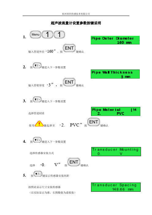
超声波流量计设置参数按键说明1.Menu
11
输入管道外径“160”,按ENT
键确认
2.按/ -键进入下一参数设置
输入管壁厚度“3”,按ENT
键确认
3.按/ -键进入下一参数设置
选择管道材质
使用键选择至“2. PVC”按ENT
键确认
4.按/ -键进入下一参数设置
选择传感器安装方式
选择“0. V”按ENT
键确认
5. 按/ -键显示传感器安装间距
按照此显示尺寸安装传感器
(以实际显示为准,右图数值为虚拟值)Tr a n s d u c e r Mo u n t i n g
0. V
Tr a n s d u c e r Sp a c i n g
148.66mm
安装完毕后,
6.键入
Menu90
显示仪器所检测到的上下游的信号强度和信号质量(Q值)。
正常工作情况下,信号强度应≥60.0。
(以实际显示为准,上图数值为虚拟值)探头安装与参数设置检查完毕后,
7.键入
Menu01
进入首页菜单显示测量结果。
(以实际测量为准)
注意:管道安装必须保证流体满管,并且在安装探头时,必须保证探头发射出的超声波始终穿插过流体介质。
Flo w 0.1129m3/h *R
Ve l 1.0415m/s。
超声波明渠流量计使用说明书
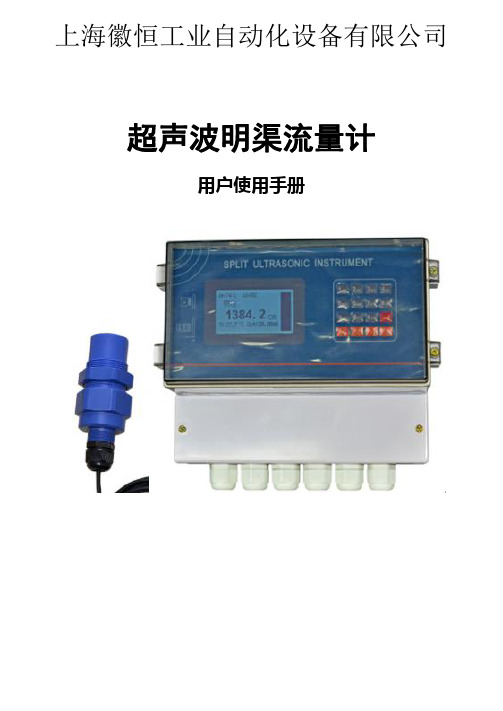
超声波明渠流量计
用户使用手册
上海徽恒工业自动化设备有限公司
目录
一 产品简介……………………………………………………………02 1.1 序言………………………………………………………….…02 1.2 超声波明渠流量计的特点…………………………………… 02 1.3 测量的原理…………………………………….....................03 1.4 技术参数………………………………………………….….04
在光标后添加字符。 (4.1)菜单状态:下翻页:下上翻菜单。 (4.2)正常工作:查看数据:查看 SD 卡中数据,显示最后
一条。 (5.11)菜单状态:上翻键:上翻页按键。 (5.2)正常工作:采集数据:采集(下载)一条数据到 SD
卡中。 (6)输入状态:符号键,长按大小写切换。 (7)输入状态:确认键。
2.1.2 快捷操作: 数字键 1:快速查看每小时历史流量。 数字键 2:快速查看每天历史流量。 数字键 3:快速查看每月历史流量。 数字键 4:快速查看每年历史流量。
2.2 产品的安装 超声波传感器配有固定螺环,预先在安装位置预留安装孔,将超声波
传感器放好后,拧紧上螺环即可。 -7-
上海徽恒工业自动化设备有限公司
如图一所示:
超声波换能器 水流方向
上游
液位观测区 下游
-3-
超声波明渠流量计主机
累计:3473 瞬时:1.245 液位:0.367M 2014年07月12日
电源
其他控制显示设备
上海徽恒工业自动化设备有限公司
图一 超声波换能器安装于上水槽上方。检测到超声波换能器端面到液面 的距离,根据超声波换能器的安装高度减去液面到超声波换能器的距离等 于流过量水槽的水位深度,将水位深度带入流量换算公式得出流量。计算 公式请查看第 10 页明渠流量计的应用,其不同的槽型其几何参数也不相 同,故使用时一定要注意设置槽型的所有参数。
超声波流量计、热量计说明书
概述本说明书只作为简易操作手册,用户需了解详细操作欢迎来电咨询。
新一代的产品继续沿用了原先铲平的操作界面,只是个别的菜单功能做了增减,同时又开发了4键盘、串口键盘和软件键盘(通过RS485连接),几种键盘可替换使用。
新一代产品增加了以下特点和功能:1、硬件模块化设计,生产及维修操作简易;2、内置4M字节数据记录器,可记录20万行定时输出或即时打印数据;3、电气隔离RS485接口,含MODBUS、M-BUS、FUJI等10多种通讯协议;4、电气隔离0-20mA或4-20mA电流环输出,可选环路供电方式(两线制);5、可选HART协议;6、符合CJ128国家热表标准的热量测量功能;7、8-36VDC,8-30VAC,220VAC供电方式可选;8、具有手动累积器及批量控制器等功能;9、年月日累积记录功能,可记录前512天(每天)、前128个月(每月)的累积流量及累积热量等数据;10、记录并查阅前32次上断电时间及其它数据;11、间隔可设定范围为1秒到24小时一次的自动数据记录或输出功能,有多大22项输出内容;12、三路精度为0.1%的模拟输入;使用前请先了解产品的工作电源和型号,防止误接造成不正常工作或损坏。
固定式超声波流量计技术特点:1、测量精度:1%;2、工作电源:隔离DC8-36V或AC85-264V;3、功耗:工作电流50mA(不连接键盘和蜂鸣器不响的条件下);4、可选输出:1路标砖隔离RS485输出;1路隔离4-20mA或0-20mA输出(有源、无源可选);可选HART协议;双路隔离OCT输出(OCT1脉冲宽度6-1000ms之间可编程,默认200ms);1路双向串行外设通用接口,可以直接通过串联的形式连接多个诸如4-20mA模拟输出板、频率信号输出板、热敏打印机、数据记录仪等外部设备;5、可选输入:三路4-20mA模拟输入回路;6、显示:2×10汉字背光显示器(中英文双语可选择);7、操作:16按键或4按键窗口化操作;8、其它功能:自动记忆前512天,前128个月,前10年正负净累积流量自动记忆前30次上、断电时间和流量并可实现自动或手动补加,并可以通过MODBUS协议读出;9、流量传感器:外敷式、插入式和管段式;手持式超声波流量计技术特点:适用于各种尺寸管道流量计量,流速测量范围为0.01~±32m/s,测量介质为水、海水、污水、酒精等单一稳定的液体,测量材质为钢、不锈钢、铸铁、PVC、玻璃钢等均匀质密的管道。
超声波明渠流量计说明书
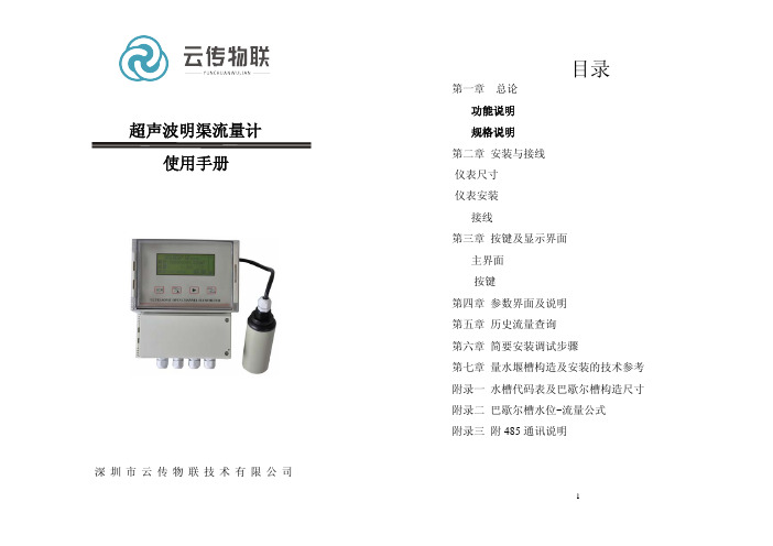
超声波明渠流量计使用手册目录第一章 总论功能说明 规格说明 第二章 安装与接线 仪表尺寸 仪表安装接线第三章 按键及显示界面主界面按键第四章 参数界面及说明 第五章 历史流量查询 第六章 简要安装调试步骤第七章 量水堰槽构造及安装的技术参考 附录一 水槽代码表及巴歇尔槽构造尺寸 附录二 巴歇尔槽水位-流量公式 附录三 附485通讯说明深圳市云传物联技术有限公司第一章总论功能说明1.组成仪表由主机(控制器)与传感器两部分组成,主机与传感器之间由5芯屏蔽电缆连接。
2.字幕(显示屏内容)显示选槽信息显示时间显示累计流量显示瞬时流量显示液位或距离显示继电器状态显示瞬时流量柱状比列图3.密码保护保护仪表内部参数不被随意修改。
4.校准方法液位校准方法:传感器底部到0液位距离设定。
5.类比输出(电流输出)提供一组4-20mA输出(0-20mA需预订),16位高精度D/A,可达750欧负载。
4mA和20mA电流点由用户根据需求自行设定。
6.继电器输出控制器由4个继电器输出。
(1)脉冲输出继电器(K1):累计值达到脉冲流量累计值,闭合1次(50ms)(2)高报警继电器(K2)(3)低报警继电器(K3)(4)备用继电器(K4):需要时按客户要求设计。
7.通讯RS485接口8.历史记录历史小时流量记录128条历史日流量记录64条历史月流量记录32条历史年流量记录4条规格说明1. 流量范围:0升/秒~100米3/秒 (由配用的量水堰槽的种类、规格确定)2. 累计流量:12位十进制数,累满后自动回零3. 流量精度:3%4. 测距范围:3米5. 测距精度:0.25%6. 液位分辩:1毫米7. 工作环境温度:-20~70℃8. 仪表防护等级:仪表显示部分:IP65;探头部分:IP679. 供电电源:交流供电 220V或DC24V(按接线座标注)10. 4~20mA电流输出:(对应瞬时流量)最大负载电阻:750Ω11. RS485接口(附485通讯说明)12. 继电器输出: 4路继电器输出脉冲输出继电器(K1):累计值达到脉冲流量累计值,闭合1次(50ms)高报警继电器(K2)低报警继电器(K3)备用继电器(K4):需要时按客户要求设计。
超声波流量计使用说明
超声波流量计使用说明一、装配1.确保流量计安装在一个水平的位置,以避免测量误差。
二、连接电源和传感器1.将流量计与电源连接,并确保电源的稳定输入。
2.连接传感器到流量计主机上的传感器接口,并确保连接牢固。
三、设置参数1.打开流量计主机,进入设定参数模式。
2.根据实际需求,设置流量计的管道直径、温度范围、压力范围等参数。
3.设置输入和输出方式,包括模拟信号和数字信号。
四、校准1.在流量计中选择校准模式,并选择合适的校准流量。
2.调整光栅设置,确保测量的准确性。
3.对比校准流量和流量计测得流量,调整校准系数,直到两者相等。
五、运行监测1.流量计进入稳定工作状态后,开始对流体进行测量。
2.实时监测流量计所得的流量值,确保测量数据的准确性。
3.警报和故障排除:如果出现异常数据或故障报警情况,需要及时采取措施进行故障排除。
六、维护保养1.定期对流量计进行检查和维护,清除可能存在的污垢或堵塞。
2.检查传感器是否正常工作,及时更换故障传感器。
3.保持流量计的清洁,避免灰尘和杂质进入流量计。
七、注意事项1.在安装和操作流量计时,应注意安全,避免触电、烫伤等事故。
2.在使用过程中,应定期校准流量计,以确保测量准确性。
3.在操作过程中,应注意防水和防尘,避免流量计损坏。
4.在使用过程中,应避免震动和冲击,以免影响测量结果。
总结:超声波流量计是一种高精度、高稳定性的流量测量仪器,使用前需要进行装配、连接电源和传感器、设置参数、校准、运行监测等步骤。
在使用过程中需要注意事项,如注意安全、定期校准、防水和防尘、避免震动和冲击等。
定期维护保养可延长设备寿命,确保测量准确性。
超声波流量计操作手册说明书
MANUAL DE OPERACIÓN MEDIDOR ULTRASÓNICO2En cada tipo de instalación, los métodos de instalación de los medidores de agua varían de manera significativa.Antes de instalar el medidor es importante considerar que el espacio sea suficiente, no sólo para su ubicación, sino para colocar los otros elementos necesarios para realizar los procesos de mantenimiento y monitoreo del medidor de agua.Debe existir espacio en ambos lados para poder acceder a ellos de forma cómoda. En caso de los modelos de gran tamaño es probable que requieran un polipasto.Para el correcto funcionamiento, se requieren estar en un tramo recto con una longitud mínima determinada.Evitar vacío, colocando la válvula check aguas arriba.min. 5 x D Considerar mínimo 5 diámetros libres antes del medidor y 3 diámetros después.min. 3 x DMANUAL - MACROMEDIDORES MECÁNICOS3El punto de colocación debe asegurar que la sección se mantenga llena durante el uso.EMPAQUE EMPAQUETambién debe evitarse su exposición a altas temperaturas y vibraciones excesivas.Se recomienda utilizar empaques en la instalación del medidor.El sensor cuenta con una flecha que indica el sentido del caudal del fluido.Restricciones del medidorInstalar el medidor de manera correcta.Evitar que el medidor quede instalado en los puntos altos del sistema de tubería.Se recomienda no instalar el medidor en posición vertical.4MANUAL - MACROMEDIDORES MECÁNICOS 5No colocar el medidor con la caratula boca abajo, esto impide el funcionamiento correcto del equipo.Se recomienda no instalar el medidor en tuberías con inclinación.Antes y después del medidor de agua, colocar válvulas para cortar el suministro de agua si hay necesidad de desinstalación o reparación. Utilice válvulas de paso para cerrar comple-tamente la sección transversal de una tubería de agua.La tubería instalada debe tener una forma tal que no haya posibilidad de que se cree una bolsa de aire en el medidor de agua. El medidor debe permanecer completamente lleno de agua.El flujo de agua a través del medidor debe corresponder a la dirección de las flechas colo-cadas en ambos lados del cuerpo.SoportesEl medidor se debe instalar sin tensión mecánica (torsión, flexión). Si es necesario, instale soportes para las tuberías.6MANUAL - MACROMEDIDORES MECÁNICOS 7El medidor de flujo debe tener un montaje seguro sobre silletas a una altura adecuada.SILLETA DE SUJECIÓNSILLETA DE SUJECIÓNLas tuberías aguas arriba y abajo del medidor deben estar apoyadas de modo seguro, de modo que estas no causen tensiones al medidor. Es importante no colocar soportes debajo del medidor de agua. Para grandes diámetros, se pueden colocar los soportes debajo de las contrabridas.8Las caratulas de los medidores de agua están regulados bajo la norma NOM-012-SCFI y el diseño está orientado para facilitar la lectura del usuario. El sistema ofrece la lectura prin-cipal en metros cúbicos, para realizar la conversión a litros es necesario considerar que 1 metro cubico equivale a 1000 litros.Para realizar la lectura del medidor se tiene que ubicar en la caratula la lectura principal, así como los submúltiplos ubicados en forma de reloj, los cuales dependerán del tipo de medidor (desde 1 hasta 4 círculos). La lectura se debe tomar de la siguiente forma:1.- Tomar el dato de la escala principal, ejemplo 32.- El siguiente valor es el que indica el primer reloj marcado como x0.1, en este caso la aguja indica un valor entre 8 y 9 por consiguiente se toma el valor inferior siendo 8, el cual lo separaremos con un punto para indicar los decimales, ejemplo3.83.- Pasar al siguiente reloj y colocar el valor a un lado del último dato, ejemplo 3.87 y así sucesivamente hasta el último reloj indicador.4.- Este dato se encuentra en metros cúbicos para convertir a litros es necesario multipli-carlo por 1000 y el resultado estará en litros.3.873 m3 x 1000 = 3873 LitrosLectura del medidorIndicador de flujo:MANUAL - MACROMEDIDORES MECÁNICOS9Sensores de pulsos (Reed switch)ComunComunPulso 1Pulso 1Pulso 2Pulso 2Sensor de pulsos W Diagrama para los siguientes modelos: • WF NOM • IF • HWFSensor de pulsos U Diagrama para los siguientes modelos: • WF • -IF-• R20010El medidor de agua es un instrumento cuya capacidad de medición cambia con el tiempo. Además, el deterioro de esta capacidad es generalmente el resultado de la influencia agre-siva del agua, por lo que, después de un tiempo debe ser desinstalado de la red, para su mantenimiento y calibración.No utilice productos químicos de limpieza que tengan una influencia perjudicial sobre los materiales de los que están hechos los elementos del medidor de agua.Las reparaciones deben realizarse por personal autorizado en plantas de servicio. Consultar a su agente de ventas.Inspección, mantenimiento y reparaciónLos medidores de agua recibidos de entregas o desinstalados de la red deben almacenarse en un lugar cerrado, libre de vapores cáusticos, etc., que puedan tener un efecto destruc-tivo en el estado de los medidores de agua.La temperatura ambiente debe estar entre 5 y 30°C, y la humedad relativa del aire no debe de ser superior al 80%. Tanto durante el transporte como durante el almacenamiento, los aparatos deben estar protegidos de las vibraciones y, en particular, de los golpes que pue-dan dañar el cuerpo o los elementos internos.El transporte debe realizarse protegiendo el embalaje del fabricante o un embalaje susti-tuto, el cual resguarde totalmente el producto de daños.Almacenamiento y transporteResolución de pulsosMANUAL - MACROMEDIDORES MECÁNICOS 11• Es importante que los medidores se manejen con cuidado debido a sus piezas mecá-nicas, durante el transporte y previo a la instalación. En caso de los equipos de gran tamaño para uso industrial, que requieren el uso de un montacargas, se debe colgar la pieza en los enganches y moverlo en un ángulo de 45°.• No transporte el medidor usando un diablito de carga colocando el cuerpo con las bridas sobresaliendo del diablito. Esto podría abollar la carcasa o dañar los ensamblajes del sistema interno.• Transportar siempre el medidor con su embalaje original.Para limpiar la carcasa del instrumento y su pantalla, use únicamente un trapo suave ligera-mente humedecido con agua o un producto para la limpieza de cristales.Nunca use solventes fuertes, ya que pueden agrietar o remover la pintura de la carcasa e incluso destrozar las partes plásticas.Evite que los cables se doblen o sufran de torsiones y nunca haga nudos. Cuando vaya a conectar o desconectar el cable de alimentación del instrumento, siempre tómelos única-mente por los conectores.NotasCuidado del medidorManejo adecuado de los cables• Si el medidor no indica nada cuando el agua fluye, compruebe si el rotor no está atas-cado por algún sólido.• Si tiene problemas al conectar el sensor de pulsos, comuniquese con el departamento de soporte técnico de Equysis.• Si tiene algún problema con su medidor, no rompa los sellos de seguridad. Y envíe el equipo a Equysis para su diagnóstico.Problemas comunes。
超声波流量计说明书简易版
§ 1.3 工作原理当超声波束在液体中传播时,液体的流动将使传播时间产生微小变化,其传播时间的变化正比于液体的流速。
零流量时,两个传感器发射和接收声波所需的时间完全相同(唯一可实际测量零流量的技术),液体流动时,逆流方向的声波传输时间大于顺流方向的声波传输时间。
§ 1.4典型用途携带式超声波流量计/能量表用于测量各种能够传导超声波的单一均匀的液体的流量及热量。
携带式超声波流量计采用非接触测量方式,测量范围大,没有活动机械部件,不受系统的压力和恶劣环境的影响,已成功应用于水、纯水、海水、污水、化工液体、江河水、燃料油等流体的计量工作中。
标准传感器的上限温度为110ºC ,超过此温度请与厂家或供应商联系。
携带式超声波能量表广泛应用于制冷、供热、换热器、冷冻机、锅炉等行业系统能量消耗行的计量。
2.主机操作快速入门§ 2.1 如何开关机按 On 键3秒打开流量计的电源,按 Off 键3秒关闭流量计的电源。
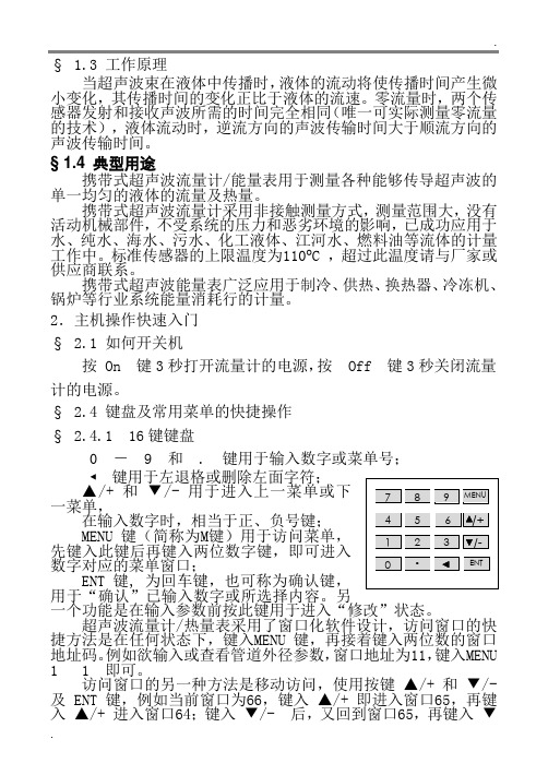
§ 2.4 键盘及常用菜单的快捷操作§ 2.4.1 16键键盘0 - 9 和 . 键用于输入数字或菜单号;◄键用于左退格或删除左面字符;一菜单,在输入数字时,相当于正、负号键;MENU 键(简称为M键)用于访问菜单,先键入此键后再键入两位数字键,即可进入数字对应的菜单窗口;ENT 键, 为回车键,也可称为确认键,用于“确认”已输入数字或所选择内容。
另一个功能是在输入参数前按此键用于进入“修改”状态。
超声波流量计/热量表采用了窗口化软件设计,访问窗口的快捷方法是在任何状态下,键入MENU 键,再接着键入两位数的窗口地址码。
例如欲输入或查看管道外径参数,窗口地址为11,键入MENU 1 1 即可。
访问窗口的另一种方法是移动访问,使用按键▲/+ 和▼/- 及 ENT 键,例如当前窗口为66,键入▲/+ 即进入窗口65,再键入▲/+ 进入窗口64;键入▼/- 后,又回到窗口65,再键入▼/- 又进入窗口66。
超声波流量计 说明书
超声波流量计说明书一、概述超声波流量计是一种高科技的流量测量仪表,它利用超声波在流体中的传播速度与流体流速之间的函数关系来测量流体的流量。
这款流量计具有高精度、高可靠性、易于安装和维护等优点,特别适合用于各种工业生产过程中的流量测量。
二、产品特点1. 高精度:超声波流量计采用先进的信号处理技术和算法,能够实现高精度的流量测量,有效避免了传统流量计在测量过程中可能出现的误差。
2. 宽测量范围:超声波流量计适用于各种流速和流量范围,能够满足不同用户的需求。
无论是小流量还是大流量,它都能准确地测量出流体的流量。
3. 无压力损失:超声波流量计在测量过程中对流体没有任何阻碍,因此不会对流体产生压力损失,从而保证了流体的流动性能。
4. 稳定性好:超声波流量计的测量部件采用高品质的材料和工艺制作,保证了长期使用的稳定性和可靠性,大大减少了维护和维修的频率。
5. 易于安装和维护:超声波流量计的安装非常简便,只需要按照说明书的要求进行安装即可。
同时,它的维护也非常方便,只需要定期清洗测量管路和检查各部件是否正常工作即可。
三、使用方法1. 安装前准备:在安装超声波流量计之前,需要先确认测量管路已经清洗干净,没有任何杂质和污垢。
同时,需要检查流量计的型号和规格是否符合要求,并检查电源和信号线是否连接正常。
2. 安装方式:根据现场的实际情况,选择合适的安装方式。
一般来说,超声波流量计的安装方式有插入式、管段式等。
按照安装说明书的步骤进行安装,确保安装牢固可靠。
3. 参数设置:根据流体类型、管道材质和尺寸等参数设置流量计的测量参数。
这些参数的设置将直接影响到测量结果的准确性和可靠性,因此需要按照说明书的要求正确设置各项参数。
4. 校准和调试:在安装完成后,需要对超声波流量计进行校准和调试,以确保其测量准确度和稳定性符合要求。
一般来说,校准和调试需要在专业人员的指导下进行。
5. 日常维护:为了保持超声波流量计的测量精度和使用寿命,需要定期对其进行检查和维护。
YYC 超声波流量计说明书
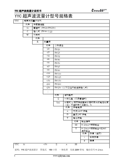
I YYC 超声波流量计型号规格表 II警告(1)YYC 超声波流量计仅限测量水、海水、污水、酒精、各种油类等能传导超声波的单一、均匀、稳定的液体;(2)YYC 超声波流量计必须满管;(3)YYC 超声波流量计禁止用手抓表头进行搬运。
错误 正确 1 1 产品介绍YYC 超声波流量计是一种根据声波在流动液体中的传播规律实现流体流量测量的流量计。
近十几年来随着集成电路技术的不断迅速发展,使得超声波流量计的精度和稳定性有了很大的提高,现已成为一种高精度、高可靠性、高性能、低功耗、低价格等优点,广泛被用户所采用。
YYC 超声波流量计在设计上采用了世界上先进的集成电路,实现了生产过程中元器件参数无调整化,生产工艺既简单又可靠,产品一致性好,保证每一台出厂的机器都达到最佳性能、最好工作状态。
YYC 超声波流量计有着广泛的用途,在满足现场监测显示的同时可输出标准直流电流信号(4~20mA)供记录、调节、控制用,另外增加了频率输出功能,有效地提高了仪表精度,广泛应用于自来水、循环水、工业用水,各种燃料油、各种酸碱液溶液、各种化学容剂等。
所有YYC 超声波流量计均由菜单驱动,输出4~20mA 流量比例信号并带有RS485通讯接口,以便与计算机进行联网通讯。
2 性能特点●导电、非导电及特殊介质测量。
●高亮度、高清晰度的点阵式液晶显示屏。
●高精度时间间隔测量(p秒级)。
●采用EEPROM存储器,测量及运算数据存贮保护安全可靠。
●年、月、日、时、分、秒时间实时显示。
●具有RS485接口,完善的Modbus通讯协议。
●内置热量测量/热量计。
●内置上电断电记录器。
●内置数据记录。
● 20毫秒基本测量周期。
●对管内流体不产生压力损失,节约能源。
●嵌入式单片机的采用,提高运算速度。
●具有掉电检测、数据保护功能,上电即可恢复运行。
●抗干扰能力强,可在恶劣环境下稳定工作,如:变频器环境能正常工作。
●探头温度范围普通型 -20℃~120℃,高温型<150℃。
- 1、下载文档前请自行甄别文档内容的完整性,平台不提供额外的编辑、内容补充、找答案等附加服务。
- 2、"仅部分预览"的文档,不可在线预览部分如存在完整性等问题,可反馈申请退款(可完整预览的文档不适用该条件!)。
- 3、如文档侵犯您的权益,请联系客服反馈,我们会尽快为您处理(人工客服工作时间:9:00-18:30)。
I YYC 超声波流量计型号规格表 II警告(1)YYC 超声波流量计仅限测量水、海水、污水、酒精、各种油类等能传导超声波的单一、均匀、稳定的液体;(2)YYC 超声波流量计必须满管;(3)YYC 超声波流量计禁止用手抓表头进行搬运。
错误 正确 1 1 产品介绍YYC 超声波流量计是一种根据声波在流动液体中的传播规律实现流体流量测量的流量计。
近十几年来随着集成电路技术的不断迅速发展,使得超声波流量计的精度和稳定性有了很大的提高,现已成为一种高精度、高可靠性、高性能、低功耗、低价格等优点,广泛被用户所采用。
YYC 超声波流量计在设计上采用了世界上先进的集成电路,实现了生产过程中元器件参数无调整化,生产工艺既简单又可靠,产品一致性好,保证每一台出厂的机器都达到最佳性能、最好工作状态。
YYC 超声波流量计有着广泛的用途,在满足现场监测显示的同时可输出标准直流电流信号(4~20mA)供记录、调节、控制用,另外增加了频率输出功能,有效地提高了仪表精度,广泛应用于自来水、循环水、工业用水,各种燃料油、各种酸碱液溶液、各种化学容剂等。
所有YYC 超声波流量计均由菜单驱动,输出4~20mA 流量比例信号并带有RS485通讯接口,以便与计算机进行联网通讯。
2 性能特点●导电、非导电及特殊介质测量。
●高亮度、高清晰度的点阵式液晶显示屏。
●高精度时间间隔测量(p秒级)。
●采用EEPROM存储器,测量及运算数据存贮保护安全可靠。
●年、月、日、时、分、秒时间实时显示。
●具有RS485接口,完善的Modbus通讯协议。
●内置热量测量/热量计。
●内置上电断电记录器。
●内置数据记录。
● 20毫秒基本测量周期。
●对管内流体不产生压力损失,节约能源。
●嵌入式单片机的采用,提高运算速度。
●具有掉电检测、数据保护功能,上电即可恢复运行。
●抗干扰能力强,可在恶劣环境下稳定工作,如:变频器环境能正常工作。
●探头温度范围普通型 -20℃~120℃,高温型<150℃。
●输出接口采用防雷保护。
2 3 3 技术数据 44 量程范围在量程Q 已确定的条件下,即可根据上述流速V 的范围决定流量计口径D 的大小,其值由下式计算:4Q 1 π VD = ² 5 5 测量精度参考条件下的仪表不确定度(显示/流量信号输出) 6 6 外型尺寸6.1 外型结构超声波有普通管道型和插入型两种结构,DN20~DN250采用普通管道型,DN80~DN1400采用插入型,具体外型见6.1.1和6.1.2。
6.1.1 普通管道型普通管道型外形结构如图6.1、图6.2所示所示,其尺寸值见表6.1图6.2 一体化型图6.1分离式表6.1 流量计外形尺寸单位:mm6.1.2插入型传感器结构外形结构如图6.3所示:图6.3插入式传感器结构7 电气连接7.1 接线方法分离式超声波流量计转换器内的外接线端子腔体内包含7组接线端子,分别是供电电源接线端子、输出信号接线端子和输入信号接线端子,如图7.1所示。
I+ I- A B Fr com RLY+ RLY- UP+ UP- GND DN+ DN- GND4~20mA R S485 频率输出 上游探头输入 下游探头输入信号输出 传感器输入外接端子接线说明:电 源: (1)脚为交流220V 电源的相线N ;(2)脚为交流220V 电源的地线GND ; (3)脚为交流220V 电源的中线L 。
(4)脚为直流24V 电源的正端V+; (5)脚为直流24V 电源的负端V-;信号输出: (6)脚为4~20mA 电流输出正端I+;(7)脚为4~20mA 电流输出负端I-。
(8)脚为RS485通讯输出A 端;图7.1T1+ T1-T2- T2+(9)脚为RS485通讯输出B端。
(10)脚为频率输出+;(11)脚为频率输出-。
(12)脚为继电器输出RLY+。
(13)脚为继电器输出RLY-。
输入信号:(14)脚为上游探头正端UP+;(15)脚为上游探头负端UP-;(16)脚为上游探头屏蔽线端GND。
(17)脚为下游探头正端DN+;(18)脚为下游探头正端DN-;(19)脚为下游探头屏蔽线端GND。
(20)脚为铂电阻PT1000热温度输入正端T1+;(21)脚为铂电阻PT1000热温度输入负端T1-。
(22)脚为铂电阻PT1000冷温度输入正端T2-;(23)脚为铂电阻PT1000冷温度输入负端T2+。
分离式传感器接线盒端子接线说明:1 2 3 4图7.2(1)脚为上游探头正端UP+;(2)脚为上游探头负端UP-;(3)脚为上游探头正端DN+;(4)脚为上游探头负端DN-;(5)脚为地线接线端。
一体化型超声波流量计接线盒接线说明如图7.3所示:只需按图所示接入电源即可,如需远程监测或控制,还需要接上电流输出线。
接线端子说明:+: 直流供电时为24V电源正级,交流供电时为220V电源的相线-: 直流供电时为24V电源负级,交流供电时为220V电源的中线I+: 电流输出正极I-: 电流输出负极7.2 接线须知电线和电缆1)采用500PVC绝缘电线或具有同等性能的标准电线或电缆。
2)在易受电噪声干扰的地方需使用屏蔽线。
3)在高温或低温环境中,要采用适合于使用场合温度的电线或电缆。
4)在空气中含有油或溶剂、腐蚀性气体或液体的地方,应采用适合于这种地方的电线或电缆。
电缆敷设1)导线可敷设在钢管或电缆沟中,也可沿墙柱敷设。
2)超声波流量计的电源线,应从安装有指示灯、电源开关和保险丝的开关板上接出。
3)传感器与转换器之间按接线图对照符号要求接线,同一导线两端应接在同样符号的端子上。
4)若传感器与转换器之间的电缆线为两段相接,则接头处应进行绝缘和防潮处理。
5)为避免干扰,信号线与电源线不要敷设在同一根钢管中;平行走线时,不要靠得太近,应保持一定的距离。
6)为避免变频干扰,信号线铺设应尽量远离变频器。
8 安装8.1 安装简图标准法兰8.2 安装条件1)尽量应远离有氨气、酸雾腐蚀性空气的场所。
如果现场环境条件不能满足,用户在订货时可以提出,本公司将设法给予解决。
2)安装流量计的管道段,不要有较大的漏电流,而且附近应有良好的接地条件。
3)安装的管道,要保证测量管道内始终充满被测介质,防止空管。
4)流量计上游侧应有不少于10D(管道内径)的直管段(见图8.1),如果上游侧有非全开的闸阀或调节阀,则流量计上游直管段的长度应增加到20D的距离(见图8.2)。
流量计下游侧的直管段要求不高,一般大于5D即可。
图8.18.3安装方法8.3.1分离式超声波流量计的转换器盒采取壁挂或支架固定的方法安装 安装孔尺寸如图8.3所示。
图8.31) 为防止出现不满管,流量计标高应略低于管道的标高,或在流量计下游侧保证有一定的水流压力,如图8.4所示。
图8.4图8.22) 流量计测量内径应与管道内径相一致,如果内径不可能一致,管道内径应大于流量计内径,并在它们之间加装圆锥角不大于15°的渐缩管或渐扩管,如图8.5所示。
3)4)对工艺上不允许流量中断的管道,在安装流量计时应加设旁路通管和清洗口,如图8.7所示,这种装置可在流量计退出使用的情况下,保证设备系统连续工作。
5) 小口径流量计可直接支撑在管道上,大口径流量计则必须安放在垫脚上,通过垫脚由地基来承受流量计重量,此时流量计下游管道的连接处,应装伸缩节。
6) 流量计法兰与管道法兰的连接螺栓必须拧紧,密封垫圈厚度要均匀,以保证连接紧密、无泄露。
密封垫圈内径应与衬里内径一致,孔口要对准,不使垫圈凸出而产生截流效应,从而影响测量精度。
≤≤7.5° 图8.5图8.7(1)安装方式超声流量计探头安装方式有Z型、V型等(见图8.8),内径大于200mm可选Z型,200mm以内可选V型。
图3 Z型安装示意图图8.8 V型安装示意图(2)安装点位置按测量点对管道的要求,选取适合安装的直管段。
为了避免水管顶段气泡和底部泥沙的影响,安装点一般选在通过管道中心水面上下45°范围内。
V型安装两探头在管道同测,必须保证在与管道轴线平行的同一直线上,Z型安装两探头在管道两测,二者连线必须通过管道中心。
在选择确定安装方式之后,主机根据输入管道尺寸,流体种类,探头类型等参数计算出两探头安装距离,并在液晶上显示,主机所显示距离为两探头顶端之间的距离,据此可选定两个安装点。
对于Z型安装,为了保证两探头固定在通过管道中心的平面上,可用坐标纸或白纸标出安装距离,以管道圆周1/2的纸长围至管道上,由纸的两条边线划出安装线,即可准确地定出两个安装点。
(3)安装方法先用锉刀和砂纸把安装点打磨平滑,将污物清除干净,亮出管道本身的色泽。
然后分别在管道和探头涂上一层耦合剂,再将探头紧贴至安装点上,使之顶端相对,按主机给出数据调准间距并要求探头和管壁间的耦合剂中不得有气泡或固体颗粒,以免影响耦合效果。
(4)调整将探头电缆接入主机电路板相应接线端子,同时也将电源线接入,检查无误之后,将电源线另一端插入220V交流供电系统,开主机电源,对探头位置进行细微调整,直到显示的数据达到稳定。
最后用钢丝带、磁表座或其它固定架等将探头固定住,便完成安装。
(1)安装点位置的确定a 、将管道参数输入主机,M23菜单选择“5、插入B 型探头”,M24菜单选择“1、Z 法安装”,运行后M25菜单即为两个传感器的中心安装距离;b 、在合适的直管段上选择一点作为传感器的一个安装中心点A ,过A 点沿圆周1/2周长处作一中间点B ,过B 点沿轴向作一直线平行于管道中心线,过B 点在直线上量取安装距离即可得到另一安装点C(如图8.9)。
B C图 8.9(2)安装球阀底座(如图8.10)a 、等于可焊接管材,只需将球阀底座直接焊接在管道外壁上,焊接时注意不能有气孔、夹渣等焊接缺陷,以防漏水;b 、对于不可直接焊的管材,需采用定制的专用管卡安装球阀底座。
图 8.10 (3)钻孔(如图8.11)a 、将开孔器密封护套与特制球阀外螺纹连接,拧紧后,打开球阀,推动钻杆直至与管道外壁接触,将手电钻于钻杆接好锁紧;b 、接通电源,在钻孔过程中,手电钻保持低速、缓慢进给,以免卡钻,甚至钻头折断;c 、待钻透后,拔出钻杆直到开孔器钻头的最前端退至球阀芯后,关闭球阀,卸下开孔器。
1 2 3 4 5 6 7 81、管道2、球阀底座3、特制球阀4、定位钻头5、ф19开孔钻6、密封套7、钻杆8、手电钻图 8.11(4)传感器的装入(如图8.12)a、将锁紧螺帽旋至传感器底部,再把传感器旋入特制球阀导向螺纹,当旋至球阀芯时,打开球阀,继续旋入传感器,直至传感器前端伸出管道内壁;b、调整好传感器的角度(两个传感器进线孔应同时向上或向下),紧固好锁紧螺帽,最后将线接好,用硅橡胶密封接线处。