台达变频器C2000使用说明书
台达变频器使用手册

台达变频器使用手册一、产品概述变频器是一种用于控制电动机转速的调速设备,其在工业生产和自动化设备中扮演着重要的角色。
台达变频器作为一种智能调速装置,可以实现电机的精准控制和节能优化运行,广泛应用于风机、泵、压缩机、输送机等设备中。
本使用手册将详细介绍台达变频器的基本操作、功能特性和维护保养等内容,旨在帮助用户更好地了解和使用该产品。
二、产品特点1. 宽电压输入范围:台达变频器可适应不同的电源输入,稳定工作在220V~440V范围内。
2. 多种控制方式:支持V/F控制、矢量控制和无传感器矢量控制,满足不同应用场景的需求。
3. 高效节能:采用先进的PWM控制技术和电机特性自学习功能,实现转速精准控制,最大限度地降低能耗。
4. 多种保护功能:具备过载、过压、欠压、短路、过热等多重保护功能,能有效保护电机和设备。
5. 可编程控制:支持多种输入输出接口,可根据实际需求进行参数设置和逻辑控制,灵活应用。
三、操作指南1. 连接电源和电机:首先将台达变频器与电源连接,确认接线无误后再连接电机。
2. 参数设置:通过操作面板或通信接口,设置电机的额定转速、最大转矩、加速度、减速度等参数。
3. 启动与停止:按下启动按钮,变频器将根据设定的参数启动电机;停止时按下停止按钮即可。
4. 转速调节:可通过操作面板或外部控制信号,对电机转速进行调节和控制。
5. 故障排除:当变频器出现故障或报警时,应及时查看故障代码表,根据代码提示进行处理。
四、功能选择1. V/F控制模式:适用于常规的风机、泵等负载类型,具有简单可靠的特点。
2. 矢量控制模式:适用于需要精准速度控制和起动扭矩的负载,如输送机、木工机床等。
3. 无传感器矢量控制模式:适用于对电机起动和速度控制要求较高的场合,例如提升机、卷揭机等。
五、维护与保养1. 清洁保养:定期清理变频器散热器和通风口,保持通风良好。
2. 环境条件:变频器应安装在干燥通风处,远离高温、潮湿和有腐蚀性的环境。
台达变频器使用说明
台达变频器使用说明一、产品概述变频器是一种将电源电流进行无级调速的电力调节设备,通过控制电源电压的频率和幅度,改变电动机的转速,并实现电动机的保护和控制。
台达变频器通过电源控制等方式,可以实现对电机的启动、制动、转向、加速、减速等操作,并具有故障自诊断、自动转换等功能,广泛应用于发电、机械制造、船舶、石化、冶金等领域。
二、安装与接线1.变频器安装时需确保周围通风良好,同时禁止靠近易燃易爆物品。
2.接线前应断开电源,并确保无电压输出。
3.变频器的输入端和输出端需正确连接,错接可能导致设备损坏。
4.确保接地良好,并连接到可靠的地方。
5.电源线需经过接地开关,以防止电源反接。
三、开机操作1.打开主电源,确认电源指示灯亮起。
2.按下“启动”按钮,变频器开始工作。
四、运行状态监控1.通过控制面板可实时监测电机的输出参数,如转速、电流、电压等,以保证电机正常运行。
2.如出现故障或异常状态,变频器会自动报警,此时需停止操作并检查故障原因。
五、故障处理1.变频器故障时,务必先停止操作,然后按照故障代码表进行诊断和排除故障。
六、注意事项1.变频器应安装在干燥、通风良好的场所,并远离高温、潮湿和腐蚀性气体。
2.变频器应定期进行检查和维护,以确保其正常运行。
3.使用变频器时应注意电源电压和频率的匹配,避免传输过程中损坏设备。
4.在停机后,应等电机完全静止后再切断电源。
5.变频器不可频繁启停,以免影响电机寿命。
6.使用过程中应注意防止灰尘、异物等进入设备内部,以免损坏电路。
7.长时间不使用时,应切断电源并进行包装、存储。
七、结语以上就是台达变频器的使用说明,希望能对用户的使用和维护提供一些帮助。
为了确保设备的正常运行,请用户按照说明书的要求进行操作,并时刻注意设备的安全使用。
台达C2000
00 驱动器参数
参数码
参数名称
00-00 驱动器机种代码识别
00-01 驱动器额定电流显示 00-02 参数重置设定
设定范围
初始值
4: 230V, 1HP
只读
5: 460V, 1HP
6: 230V, 2HP
7: 460V, 2HP
8: 230V, 3HP
9: 460V, 3HP
10: 230V, 5HP
(Hz) (J.)
37: 保留
38: 驱动器状态(6.)
39: 显示交流电机驱动器估算之
输出正负转矩,以 Nt-m 为单
位(t 0.0:正转矩;- 0.0:负
转矩)(C.)
40: 转矩命令(L.) (单位: %)
41: KWH 显示(J) (单位:KWH)
42: PID 目标值(h.) (单位: %)
号值 (2.)(单位: %)
13:显示 AUI 模拟输入端子之讯
号值 (3.)(单位: %)
3
14:显示驱动器功率模块 IGBT
的温度 (i.)(单位: ℃)
15:显示驱动器电源电容的温度
(c.)(单位: ℃)
16:数字输入 ON/OFF 状态(i)
17:数字输出 ON/OFF 状态(o)
18:显示正在执行多段速的段速
动
2 : Local/Remote 切 换 , 维 持 Remote 的频率与运转状态 3 : Local/Remote 切 换 , 维 持
0
Local 的频率与运转状态
4:Local/Remote 切换, 维持两
者的频率与运转状态
0:由键盘输入
1:由通讯 RS485 输入
2:由外部模拟输入(参数 03-00)
台达变频器使用手册
台达变频器使用手册一、台达变频器简介台达变频器是台达公司推出的一款高性能变频器,具有高效率、低噪音、节能环保等特点,适用于各种工业应用场景。
本手册将详细介绍台达变频器的使用方法、注意事项和维护保养技巧。
二、设备连接1. 电源连接:将变频器的输入端子连接到电源,通常为三相交流电源(380V)。
2. 电机连接:将变频器的输出端子连接到电机,确保正确匹配电机和变频器的规格。
3. 控制线连接:将控制信号线连接到变频器的控制端子,用于手动或远程控制变频器。
4. 接地:确保所有连接均已牢固连接并接地,以减少电气干扰。
三、参数设置1. 模式选择:通过控制面板或外部控制信号选择所需的运行模式。
2. 频率设定:通过控制面板或外部控制信号设置变频器的输出频率。
3. 电压/电流限制:设置变频器的电压和电流限制,以防止过压和过流。
4. 加速时间/减速时间:根据实际应用需求设置加速时间和减速时间。
5. 其他参数:根据具体应用需求设置其他参数,如PWM模式、制动方式等。
四、运行操作1. 启动:将变频器置于运行模式,通过控制面板或外部控制信号启动变频器。
2. 停止:将变频器置于停止模式,通过控制面板或外部控制信号停止变频器。
3. 手动调整:通过控制面板或外部控制信号手动调整输出频率和电压。
4. 故障复位:当变频器出现故障时,按下控制面板上的故障复位按钮,复位故障并继续运行。
五、故障处理1. 常见故障:如过压、欠压、过流、过热等,可通过控制面板上的故障指示灯指示故障类型。
2. 故障排除:根据控制面板上的提示,对照台达变频器的故障代码表进行故障排除。
如需更换部件,请按照说明书中的步骤更换。
3. 紧急停车:如遇到紧急情况,按下控制面板上的紧急停车按钮,变频器将立即停止运行。
再次按下该按钮,变频器将恢复正常运行。
六、注意事项1. 使用前请仔细阅读产品说明书和操作手册,正确使用和维护设备。
2. 在连接和控制变频器时,确保操作正确、安全,避免电击和短路风险。
台达C2000调试
台达C2000调试需要增加PG卡EMV-PG01L,在接线时候要接编码器的黑/A1,白/B1,VP棕色,COM接A1/,B1/,兰色和屏蔽网。
1.调试顺序1.先00-02调到10,10:参数重置(基底频率为60Hz)电机参数设置05-01电机满载电流(A) 11.405-02电机额定功率(kW)5.505-03电机额定转速(rpm)144005-04电机极数4级05-05电机无载电流(监控开开的电流)其它步骤按说明PG卡设计:10-00编码器(Encoder) 种类选择1:ABZ10-01编码器(Encoder)每转脉波数100010-02编码器(Encoder)输入型式设定1:A/B 相脉波列A 相超前B 相90 度为正转2:A/B 相脉波列B 相超前A 相90 度为正转其它步骤按说明惯量设定为1-12设为4.00s 1-13设为2.00s2.最后设计先00-10控制模式设为2:转矩模式00-11速度模式控制选择设为3:IM FOCPG(磁场导向向量控制+编码器)00-13转矩模式控制选择设为0:TQCPG(转矩控制+编码器)00-20频率指令来源设定设为2:由外部模拟输入(参数03-00)00-21运转指令来源设定设为1:外部端子操作先在为0时候在面板上面运行操作。
02-03多功能输入指令三(MI3) 39:转矩命令方向03-00 AVI 模拟输入功能选择2:转矩命令(速度模式下的转矩限制) 11-33转矩命令来源2:模拟讯号输入(参数03-00)需要先设置为0,在下面范围来手动调试11-34转矩命令100.0%11-36速度限制选择0:参数11-37~11-3811-37转矩模式正方向速度限制100.0%11-38转矩模式反方向速度限制100.0%01-10 上限频率60HZ。
台达变频器使用手册
台达变频器使用手册一、引言台达变频器是一种用于控制电动机转速的设备,具有广泛的应用领域。
本使用手册旨在提供对台达变频器的全面了解和正确操作指导,帮助用户充分发挥其功能和效能,确保安全操作和长期可靠运行。
二、产品概述1. 产品介绍台达变频器是一种用于控制三相交流电动机的转速、转矩和保护设备。
具有多种控制模式、广泛的应用领域和高性能参数。
2. 技术规格台达变频器的技术规格包括额定电流、额定电压、频率范围、输出功率、环境要求等。
用户在选择合适的变频器时应根据实际需求和技术规格进行匹配。
三、安装和调试1. 安装指导(1)选择安装场所:确保变频器安装在通风良好、干燥、无腐蚀性气体和易燃、易爆物质的场所。
(2)安装方式:根据变频器的类型和安装要求选择合适的安装方式,确保固定牢固、线缆连接可靠。
2. 电气连接(1)电源连接:根据变频器的额定电压和电流要求,正确连接输入电源。
(2)电动机连接:根据变频器的输出要求,正确连接电动机。
3. 参数设置根据实际需求,设置变频器的频率、转矩、过载保护等参数,确保其能够满足工作要求,并保证安全和高效运行。
四、操作指导1. 启动和停止(1)启动:按下启动按钮,变频器将根据预设的参数逐渐提升电机转速。
(2)停止:按下停止按钮,变频器将逐渐减速并停止电机运行。
2. 运行控制变频器提供多种运行控制方式,包括手动、自动和远程控制等。
用户可根据实际情况选择合适的控制方式,并通过相应的操作界面进行设置和调整。
3 . 故障诊断和保护台达变频器具有故障诊断和保护功能,可监测电机运行状态并及时发出警报。
用户应根据变频器提供的故障代码和手册中的故障排除指南进行操作,以保障设备的正常运行。
五、维护和保养1. 清洁定期将变频器表面和散热器上的灰尘清理干净,确保其散热性能良好。
2. 检查定期检查变频器的连接器、电源和控制线路的接触情况,确保其连接可靠。
3. 维护根据变频器的维护周期和要求,进行相应的维护工作,如更换电解电容、清洁风扇等。
台达C2000变频器调试数据
C2000-1VFD-C2000P R C 350116975032013-04黄承刚专用C2000-2NOTE123用2U00-04 3A00-040A1c2H.3DC-BUS v4U, V, WE5n6kWP7rpmr8%,100%t9PG G(10-0010-01)10PID%b11AVI% 1.12ACI% 2.13AUI% 3.14IGBTi.15c.16ON/OFF i17ON/OFF o18S19CPUd.20CPU0.21(PG PG 1)P.22(PG PG 2)S.23(PG PG 2)q.24E.25(0.00~100.00%)(h.)26GFF(:%)(G.)27Dcbus(:Vdc) (r.)28PLC D1043C29(EMC-PG01U)(4.)30(U)3100-05(K)32:3黄承刚专用C2000-3(PG Z) (Z.)33:(PG)(q)34:(%) (F.)35:0:(SPD); 1:(TQR) (t.)36:(Hz) (J.)37:38:(6.)39:Nt-mt 0.0- 0.0C.40:%(h.)41: KWH KWH(J)42: PID%(L)43: PID%(o.)44: PID,Hz(b.)00-050~160.00 1 00-06#.#00-070655350~200-08065535000-07100-0900-10012300-11 0: VF V/F1: VFPG V/F+2: SVC3: FOCPG+4: FOCPG+5: FOC Sensorless()6: PM Sensorless ()00-120100-130: TQCPG+1: TQCPG (+)2: TQC Sensorless ()00-14 00-1500-1601黄承刚专用C2000-400-17230V [460V]1-15HP [1-20HP] 2~15KHz20-50HP [25-75HP] 2~10KHz60-125HP [100-475HP] 2~09KHz 230V [460V]1-15HP [1-20HP] 2~15KHz20-50HP [25-75HP] 2~10KHz60-125HP [100-475HP] 2~09KHz864200-1800-19 PLC Bit 0: PLCBit 1: PLCBit 2: PLCBit 3: PLC00-1900-20AUTO 01RS485203-003up/down4(Pulse)(10-16)5(Pulse)(10-16)6CANopen78(CANopen)00-21AUTO 012RS-4853CANopen45(CANopen)00-220100-2301200-2400-25Bit 0~3:0000b:0001b: 10010b: 20011b: 3Bit 4~15:000xh: Hz001xh: rpm002xh: %003xh: kg004xh: M/S005xh: kW006xh: HP007xh: PPM008xh: l / m009xh: kg/s00Axh: kg/m00Bxh: kg/h00Cxh: lb/s00Dxh: lb/m00Exh: lb/h00Fxh: ft/s010xh: ft/m黄承刚专用C2000-5C2000-6011xh: M 012xh: ft 013xh: degC 014xh: degF 015xh: mbar 016xh: bar 017xh: Pa 018xh: kPa 019xh: mWG 01Axh: inWG 01Bxh: ftWG 01Cxh: Psi 01Dxh: Atm 01Exh: L/s 01Fxh: L/m 020xh: L/h 021xh: m3/s 022xh: m3/h 023xh: GPM 024xh: CFM 00-260~65535 (00-25)0.0~6553.5 (00-251)0.0~655.35 (00-252)0.0~65.535 (00-253)00-2700-2800-29LOCAL/REMOTE0HOA 1Local/Remote 2Local/Remote ,Remote3Local/Remote ,Local4Local/Remote ,00-30HAND01RS485203-003up/down 4(Pulse)(10-16)5(Pulse)(10-16) 6CANopen78(CANopen)000-31HAND012RS-485 3CANopen45(CANopen )000-32STOP0:STOP 1:STOP00-33~00-39黄承刚专用C2000-7黄用台达C2000变频器.pdf调试数据Array用C2000-801-45=10.0~250.00.201-27S201-45=00.00~25.0001-45=10.0~250.00.200.201-2810.00~600.00Hz 0.00 01-2910.00~600.00Hz 0.00 01-3020.00~600.00Hz 0.00 01-3120.00~600.00Hz 0.00 01-3230.00~600.00Hz 0.00 01-3330.00~600.00Hz 0.0001-34012Fmin (01-0701-41)01-3520.00~600.00Hz 60.00/ 50.0001-362230V0.0V~255.0V460V0.0V~510.0V200.0400.001-37210.00~600.00Hz 3.0001-3821230V0.0V~240.0V460V0.0V~480.0V11.022.001-39220.00~600.00Hz 0.5001-4022230V0.0V~240.0V460V0.0V~480.0V2.04.001-4120.00~600.00Hz 0.0001-422230V0.0V~240.0V460V0.0V~480.0V0.00.001-43 V/F 001-00~01-081 1.52201-440123401-12~01-2101-45S00.0110.101-46CANopen01-45=0: 0.00~600.0001-45=1: 0.0~6000.01.00黄承刚专用C2000-9用C2000-103738EEPROM394041HAND42AUTO4302-4844NL45PL46ORG47484950dEb51PLC bit 0 52PLC bit 1 53CANopen54~5556: Local/Remote57~70:02-09UP/DOWN 0up/down1up/down(02-10)02-10UP/DOWN0.01~1.00Hz/ms 0.0102-11 0.000~30.0000.005 02-120000h~FFFFh0N.O.1N.C.0000 02-13 1 RY1 011 02-14 2 RY2 1 1 02-16 3 (MO1)20 02-17 4 (MO2)3 1 (02-22)002-36(MO10)4 2 (02-24)002-37(MO11)5()002-38(MO12)6STOP()002-39(MO13)71(06-06~06-08)002-40(MO14)82(06-09~06-11)002-41(MO15)9002-42(MO16)10LV(06-00)002-43(MO17)11002-44(MO18)12(02-32)002-45(MO19)13(06-15)002-46(MO20)14(07-00)0 15PID16(oSL)17002-20黄承刚专用C2000-11C2000-1218002-1919 B. B.(BaseBlock) 20 21 22 23 24 25262702-33(>= 02-33) 2802-33,(<=02-33) 2902-34 (>= 02-34) 3002-34 (<= 02-34)31Y 32 33()34Stop ()35 1 (06-23) 36 2 (06-24) 37 3 (06-25) 38 4 (06-26) 39 (10-19)40 41424302-4744(06-71~06-73)45UVW 46dEb 47 484950CANopen51RS485 5253~6202-180000h~FFFFh 0N.O.1N.C.000002-19(0)0~65500 0 02-20(0)0~65500 0 02-21(DFM)11661 02-22 1 0.00600.00Hz 60.00/50.0002-2310.00600.00Hz 2.0002-242 0.00600.00Hz 60.00/50.0002-2520.00600.00Hz 2.0002-320.000~65.000 0.00002-330~100%黄承刚专用02-340.00~600.00Hz PG3.0002-3501002-470~65535 rpm 0 02-480.01~600.00Hz 60.00 02-490.000~65.0000.000 02-5002-5102-52PLCPLC02-53PLCPLC02-5402-5502-5602-57420~150%0 02-58420.00~655.35Hz0.00黄承刚专用C2000-13用C2000-14C2000-155DC Bus6789AVI10ACI 11AUI 12Iq 13Iq 14Id 15Id 16Vq 17Vd 1819PG220CANopen 21RS485222303-21AFM 10~500.0% 100.003-22AFM 1010V0-10V25-0V5-10V 003-24AFM 20~500.0% 100.003-25AFM 2010V0-10V25-0V5-10V003-2603-27AFM2-100.00~100.00% 0.0003-28AVI 0: 0-10V 1: 0-20mA 2: 4-20mA 003-29ACI 0: 4-20mA 1: 0-10V 2: 0-20mA003-30PLCPLC03-31AFM2 0-20mA 0: 0-20mA 1: 4-20mA 003-32AFM10.00~100.00% 0.0003-33AFM20.00~100.00% 0.0003-3403-35AFM10.00 ~ 20.00 0.0103-36AFM20.00 ~ 20.00 0,0103-37~03-4903-500:1: AVI 2: ACI3: AVI & ACI 4: AUI5: AVI & AUI 6: ACI & AUI黄承刚专用7: AVI & ACI & AUI03-51 AVI 03-28=0, 0.00~10.00V03-280, 0.00~20.00mA0.0003-52AVI0.00~100.00% 0.0003-53 AVI 03-28=0, 0.00~10.00V03-280, 0.00~20.00mA5.0003-54AVI0.00~100.00% 50.0003-55 AVI 03-28=0, 0.00~10.00V03-280, 0.00~20.00mA10.0003-56AVI0.00~100.00% 100.0003-57 ACI 03-29=1, 0.00~10.00V03-291, 0.00~20.00mA4.0003-58ACI0.00~100.00% 0.0003-59 ACI 03-29=1, 0.00~10.00V03-291, 0.00~20.00mA12.0003-60ACI0.00~100.00% 50.0003-61 ACI 03-29=1, 0.00~10.00V03-291, 0.00~20.00mA20.0003-62ACI0.00~100.00% 100.0003-63AUI0.00~10.00V 0.0003-64AUI0.00~100.00% 0.0003-65AUI0.00~10.00V 5.0003-66AUI0.00~100.00% 50.0003-67AUI0.00~10.00V 10.0003-68AUI0.00~100.00% 100.0003-69AUI0.00~10.00V 0.0003-70AUI0.00~100.00% 0.0003-71AUI0.00~-10.00V -5.0003-72AUI0.00~-100.00% -50.0003-73AUI0.00~-10.00V -10.0003-74AUI0.00~-100.00% -100.00黄承刚专用C2000-16用C2000-1704-55PLC60~65535 0 04-56PLC70~65535 0 04-57PLC80~65535 0 04-58PLC90~65535 0 04-59PLC100~65535 0黄承刚专用C2000-18用C2000-19W-Hour05-29KW-Hour#.#05-30KW-Hour#.#05-31()00~143905-32()00~6553505-330:1:05-340.00~655.35Amps 0.00 05-350.00~655.35kW 0.00 05-360~65535rpm2000 05-370~6553510 05-380.0~6553.5kg.m20.0 05-390.000~65.5350.000 05-40Ld0.00~655.35mH 0.000 05-41Lq0.00~655.35mH 0.000 05-420.0~360.00.0 05-43Ke0~65535 (: V/1000rpm) 0黄承刚专用C2000-20用C2000-21C2000-22 06-15OH 0.0~110.085.006-160100% (06-0306-04)5006-170 0 06-181ocA 0 06-192ocd 0 06-203ocn 0 06-214GFF 0 06-225occ IGBT 0 6ocS 7ovA 8ovd 9ovn 10ovS 11LvA 12Lvd 13Lvn 14LvS 15OrP 16oH1 (IGBT )17oH2 (40HP )18tH1o (TH1 open IGBT )19tH2o (TH2 open )2021oL (150%)22EoL1 (1)23EoL2 (2)24oH3 (PTC) 2526ot1 1 27ot2 2 28uC 29LMIT 30cF131cF23233cd1 U34cd2 V35cd3 W36Hd0 cc37Hd1 oc38Hd2 ov39Hd3 occ IGBT40AUE41AFE PID42PGF1 PG43PGF2 PG44PGF3 PG45PGF4 PG黄承刚专用C2000-23 46PGr1 PG ref 47PGr2 PG ref 48ACE 49EF 50EF151bb 52Pcod 5354CE155CE256CE357CE458CE10 Time Out 59CP10 PU Time out 60bF 61ydc Y-62dEb63oSL64ryF65 : PGF5 PG Card66~6768Sensorless69Sensorless70Sensorless 71~72:73S174~78:79: Uoc U80: Voc V81: Woc W82: OPHL U83: OPHL V84: OPHL W 85:86:87~89:90PLC100:101CGdE CANopen1102CHbE CANopen2103CSYE CANopen104CbFE CANopen105CIdE CANopen106CAdE CANopen107CFrE CANopen111InrCOM06-23 1 0~65535(bit )0 06-24 2 0~65535(bit )0 06-25 3 0~65535(bit )0黄承刚专用C2000-24 06-26 4 0~65535(bit )0 06-27 2 ( 2) 012206-28 2( 2) 30.0~600.060.006-29 PTC 012306-30 PTC 0.0100.0% 50.006-31 0.00~655.35 Hz06-32 0.00~655.35 Hz06-330.0~6553.5 V06-340.0~6553.5 V06-350.00~655.35 Amp06-36IGBT 0.0~6553.506-37Heat Sink 0.0~6553.506-38rpm 0~6553506-39 0~6553506-400000h~FFFFh06-410000h~FFFFh06-420000h~FFFFh 06-4306-4406-45(OPL) 012306-460.000~65.5350.50006-47 0.00~655.35%1.0006-480.000~65.5350.10006-4906-50 06-5106-52 06-53OrP 01006-5406-55012(0)06-56 PT10010.000~10.000V 5.00006-57 PT10020.000~10.000V 7.00006-58PT10010.00~600.00Hz 0.0006-5906-60GFF 0.0~6553.5 % 60.0黄承刚专用C2000-25 06-61GFF 0.0~6553.5 % 0.1006-62dEb 230V : 0.0~220.0 Vdc 460V : 0.0~440.0 Vdc 180.0/360.006-6306-6406-6506-6606-6706-6806-6906-7006-71 0.0 ~ 6553.5 % 0.0 06-72 0.00 ~ 655.35 0.0006-730 :1 :2 :3 : 0黄承刚专用C2000-26C2000-27 07-26V/FSVC 0~100 07-27V/FSVC 0.00~10.000.0007-2807-290.0~100.0%007-300.0~10.01.007-310123007-32 0~10000100007-330.0~6000.060.0黄承刚专用黄C2000-28C2000-29C2000-30 -11:-12:PLC 09-32~09-3409-35 PLC 1~254 2 09-36CANopen 0: Disable 1~127009-37CANopen 01M 1500k 2: 250k 3: 125k 4: 100k ()5: 50k 009-38 CANopen 1.00 ~ 2.00 1.0009-39 CANopen bit 0CANopen Guarding Time out bit 1CANopen Heartbeat Time out bit 2CANopen SYNC Time out bit 3CANopen SDO Time out bit 4CANopen SDO buffer overflow bit 5Can Bus Off bit 6Error protocol of CANopen 009-40CANopen 01CANopen DS402109-41 CANopen 0Node Reset State 1Com Reset State 2Boot up State 3Pre Operation State 4Operation State 5Stop State 09-42CANopen 0Not Ready For UseState 1Inhibit Start State 2Ready T o Switch On State 3Switched On State 4Enable Operation State 7Quick Stop Active State 13Err Reaction Active State 14Error State 09-43CANopenbit0: CANopen 20XX 0bit1: CANopen 264X 0bit2: CANopen26AX 0bit3: CANopen60XX 06553509-4409-45CANopen 0: Disable 1:Enable 009-46 CANopen 1~127 100 黄承刚专用C2000-31 09-47~09-5909-6001DeviceNet Slave2Profibus-DP Slave3CANopen Slave/Master 4Modbus-TCP Slave5EtherNet/IP Slave6~8##09-61 ## 09-62 ## 09-63 ## 09-64~09-6909-70DeviceNet: 0-63Profibus-DP: 1-125 109-71Standard DeviceNet:0: 125Kbps1: 250Kbps2: 500Kbps3: 1Mbps ()Non standard DeviceNet: ()0: 10Kbps 1: 20Kbps2: 50Kbps3: 100Kbps 4: 125Kbps5: 250Kbps6: 500Kbps7: 800Kbps8: 1Mbps209-720:0123DeviceNet1:DeviceNetCANopen(0-8)09-7309-7409-75IP Configuration0IP1IP (DHCP) 009-76IP 1 0~255 0 09-77IP 2 0~255 0 09-78IP 3 0~255 0 09-79IP 4 0~255 0 09-80 1 0~255 0 09-81 2 0~255 0 09-82 3 0~255 0 09-83 4 0~255 0 09-84Getway10~255 0 09-85Getway 20~255 0 09-86Getway 30~255 0 09-87Getway 40~255 0 09-88(Lowword) 0~255 0黄承刚专用C2000-32 09-89(Highword) 0~255 0 09-9001009-91Bit 0: Enable IP Filter :Bit 1: Internet parametersenable(1bit)EnablebitDisable Bit 2: Login passwordenable(1bit)EnablebitDisable09-92Bit 0: password enableEnablebit EnablebitDisable黄承刚专用C2000-33C2000-34 10-21PG20.000~65.5350.10010-22PG20:1: ()010-23 10-24 FOC&TQC 0~65535 0 10-25 FOC 20.0~100.0Hz 40.010-26FOC 0.0~10.0%fN 2.0 10-27FOC 1~1000ms 50 10-28FOC 33~100%Tr 100 10-29 0.00~100.00Hz 20.0010-30 Resolver 1~50 1 10-31I/F 0~150%Irated ()4010-32PM FOC Sensorless 0.00~600.00Hz 5.0010-33 10-34PM Sensorless 0.00~655.35 Hz 1.0010-35 10-36 10-37PM Sensorless 0000~FFFFh 000010-3810-39I/F PMSensorless 0.00~600.00Hz 20.0010-40PM SensorlessV/F 0.00~600.00Hz20.0010-41I/F Id 0.0~6.0sec0.2 10-42 0~20ms510-43PG 0~655.35黄承刚专用C2000-35C2000-36 11-38 1(00-20)11-37/11-382(00-20)11-37 0~120% 10 11-38 0~120% 10 11-39 01011-40 0:1:2: RS4853: CAN 4: PLC5:11-41 11-42 0000~FFFFh 000011-43 0.00~327.67Hz 10.0011-44 0.00~655.35 1.0011-45 0.00~655.35 3.00黄承刚专用。
C2000-A2-SMD4240-AF5 使用说明书

2021年3⽉25⽇更新C2000-A2-SMD4240-AF5 使⽤说明书Wi-Fi ⇋ 2AI + 4DI + 4DO0-20mA / 16bit远程 I/O 模块 — Wi-Fi I/O 模块深圳市中联创新⾃控系统有限公司Shenzhen United Innovation Automatic Control System Co., Ltd.2555666777991112131414151515151515151515151515161616161616171717171819222324242628282829293131323535⽬录⽬录1. 快速使⽤1.1. 使⽤前准备1.2. 设备接线1.3. 软件设置及设备调试1.3.1. 切换 AP 模式1.3.2. 搜索 Wi-Fi 1.3.3. 设备安装1.3.4. 设备搜索及参数设置1.3.5. 设备调测2. 硬件说明2.1. 技术参数2.2. 产品外观2.3. 指⽰灯2.4. 端⼝说明2.5. 尺⼨2.6. 安装⽅式3. 产品功能3.1. DI 采集3.1.1. DI 采集类型3.1.2. DI 主动上传3.2. AI 采集3.3. DO 控制3.3.1. DO 状态3.3.2. DO 上电状态3.4. RS485级联3.5. 其他功能3.5.1. DI 滤波器参数3.5.2. DI 脉冲计数3.5.3.3.5.4. DI ⾃动清零3.5.5. DO ⼯作模式3.5.6. AI 模块滤波参数3.5.7. AI 模块采样范围3.5.8. AI ⼯程量⾼(低)点标定4. 软件操作4.1. 切换 Wi-Fi 模式4.2. 使⽤软件进⾏配置4.2.1. 软件安装4.2.2. 软件界⾯及功能介绍4.2.3. 设置设备参数4.2.4. 设备状态查看4.2.5. 设备状态控制4.2.6. 设备参数修改4.2.7. 远程设置5. Web 配置6. 通信协议6.1. 寄存器列表6.1.1. 通⽤寄存器6.1.2. 波特率代码表6.1.3. ⽹络参数寄存器6.1.4. SOCKET 参数寄存器6.1.5. 串⼝参数寄存器6.1.6. DI/DO/AI 参数寄存器6.2. 协议应⽤⽰例 根据前⾯的设置和设备建⽴好Socket 连接后通过Modbus 协议即可取得设备数据,设备的单元表⽰固定为0xFF 。
C2000使用手册

TMS320C2000系列DSP寄存器及初始化TMS320LF240X系列DSP使用时,在掌握了其工作原理和过程之后,就要熟练使用DSP自带的一些资源如:IO口、DSRM、SRAM、EVA、,EVB、SCI、SPI、ADC和WD等等;对这些资源的使用很重要的一点就是对其合理配置和初始化,初始化的关键就是对其相关寄存器的设置,设置寄存器必须了解各位的含义,记住每位的含义是不大现实的;为此,我们专门设计了DSP初始化子程序,注明每个模块所用到的寄存器以及每位的含义,以方便设计。
=================================================DSP系统初始化=================================================ARB---辅助寄存器指针缓冲器:当ARP被加载到ST0,除了使用LST指令外,原有的ARP值被复制到ARB中当通过LST#1指令加载ARB时,也把相同的ARB值复制到ARPARP---辅助寄存器指针:ARP选择间接寻址时当前的辅助寄存器AR当ARP被加载时,原有的ARP值被复制到ARB 寄存器中在间接寻址时,ARP可由存储器相关指令改变,也可由LARP,MAR,和LST指令改变当执行LST#1指令时,ARP也可加载每ARB相同的值C---- 进位位:此位在加法结果产生进位时被置为1,或在减法结果产生借位时被清0否则,除了执行带有16 位移位的ADD或SUB指令外,C在加法后被清除或在减法后被设置在ADD或USB指令时,ADD仅可对进位位进行置位而SUB仅可对进位位进行清除,而不会对进位位产生其他影响移1位和循环指令也可影响进位位C,以及SETC、CLRC和LST指令也可影响C条件转移、调用和返回指令可以根据C的状态进行执行复位时C 被置1CNF---片内DARAM配置位:若CNF=0,可配置的双口RAM区被映射到数据存储空间若CNF=I,可配置的双口RAM 区被映射到程序存储空间CNF位可通过SETC CNF,CLRC CNF和LST指令修改R/S/复位时CNF置为0 DP----数据存储器页指针:9位的DP寄存器与一个指令字的低七位一起形成一个16位的直接寻址地址INTM---中断模式位:当INTM被置为0时,所有的未屏蔽中断使能当它被置1,所有可屏蔽中断禁止OV----溢出标志位:该位保存一个被锁存的值,用以指示CALU中是否有溢出发生一旦发生溢出,OV位保持为1直到下列条件中的一个发生时才能被清除OVM---溢出方式位:当OVM=0时,累加器中结果正常溢出当OVM=1时,根据遇到溢出的情况,累加器被设置为它的最大正值或负值SETC指令和CLRC指令分别对该位进行置位和复位PM----乘积移位方式:若PM=00,乘法器的32位乘积结果不移位直接装入CALU若PM=01,PREG输出左移1位后装入CALU,最低位LSB以0填充若PM=10,PREG输出左移4位后装入CALU,最低位LSB以0填充若PM=11,时PREG输出进行符号扩展右移六位SXM----符号扩展方式位:当SXM=1时,数据通过定标移位器传送到累加器时将产生符号扩展SXM=0将抑制符号扩展SXM位对某些指令没有影响TC---- 测试/控制标志位:在下述情况之一,TC位被置1:由BIT或BITT指令测试的位为1当利用NORM指令测试时,累加器的两个最高有效位"异或"功能为真条件转移、调用和返回指令可根据TC位的条件来执行BIT、BITT、CMPR、LST和NORM指令影响TC位XF---- XF引脚状态位:该位决定XF引脚的状态SETCXF指令可对位XF进行置位,而CLRCXF指令可对其进行清0复位时XF置1SCSR1--系统控制和状态寄存器1---地址7018HD15---保留位D14---CLKSRC。
台达变频器使用手册
台达变频器使用手册一、简介台达变频器是一种用于控制交流电动机速度和扭矩的设备,可用于诸如泵、风机、输送带等应用中。
该使用手册旨在向用户介绍台达变频器的基本操作,故障排除和维护等内容。
二、安全须知1. 在使用台达变频器前,务必确保设备连接正确,接地良好,并使用符合要求的配电线路。
2. 使用过程中严禁擅自拆卸设备,以免造成触电或短路。
3. 使用手册中提供的操作指南需严格遵守,以确保自身和设备的安全。
三、基本操作1. 电源连接:将台达变频器与电源连接,并确保输入电压与变频器额定电压一致。
2. 控制面板:通过控制面板设置所需的输出频率、运行状态等参数。
3. 电机连接:连接交流电动机至台达变频器的输出端口,并确保连接牢靠。
4. 启动运行:按照使用手册指引,设置好参数后,可通过“启动”按钮启动设备的运行。
四、故障排除1. 变频器无法启动:检查电源连接是否正常,装置是否接通,如均正常,建议检测控制面板及输出端口连接。
2. 输出频率不稳定:检查输入电压稳定性,拔掉输出端口负载,检测输出频率是否正常。
3. 风扇异常声音:停机后检查风扇是否有异物进入,如有异物可通过专业人员清理。
五、维护保养1. 定期清洁:保持变频器外表清洁,避免灰尘进入影响设备散热。
2. 定期检测:定期检查设备连接,确保连接良好,并清洁风扇,保证设备散热。
3. 外部绝缘检查:定期检查设备的外部绝缘情况,确保设备安全运行。
若发现局部绝缘损坏,应立即停机维修。
六、注意事项1. 在操作变频器时,严禁擅自改变设备参数,以免影响设备稳定性和寿命。
2. 若遇突发故障无法排除,请及时联系厂家或专业维修人员,切勿私自更换部件。
3. 变频器处于运行状态下,严禁接近高压端,以免发生触电事故。
七、结语该使用手册旨在向用户介绍台达变频器的基本使用、故障排除和维护保养等内容,旨在帮助用户正确、安全地使用这一设备。
希望用户在使用台达变频器时,能够仔细遵守操作规程,确保设备运行安全稳定。
台达变频器说明书

当用户拿到产品机种时,请参考下列步骤,以确保使用安全。
1)打开包装后,先确认产品是否因运送途中有所损坏。
检查并确定外箱及机身的铭牌标签,是否相符合。
2)确认配线是否该变频器的电压范围。
安装变频器时,请参照安装手册内容说明进行安装。
3)连接电源前,请先确认连接电源、马达、控制板、操作面板等等,是否正确安装。
4)变频器在进行配线时,请留意输入端子「R/L1、S/L2、T/L3」与输出端子「U/T1、V/T2、W/T3」接线位置,请勿接错端子以避免造成机器损坏。
5)通电后,藉由数字操作器(KPMS-LE01)设定各参数群。
先以低频率试运转,慢慢调高频率到达指定的速度。
1-1 铭牌说明1-2 型号说明1-3 序号说明1-4 接地短路片说明接地短路片:(1) 变频器内部装置有突波吸收器(Varistor / MOVs),安装于电源输入相对相间与相对地间,防止电源端的瞬间雷击高压突波造成变频器非预期的停机或损坏,安装于相对地间的突波吸收器对地透过短路片连接,保护电源对大地间的高压突波,移除将失去其相对地间的保护作用。
(2) 内建EMC滤波器机种,其中共模电容电路透过短路片与地端连接,产生高频噪声回路路径,隔绝高频干扰,移除短路片将降低EMC 滤波器效能。
EMC滤波器中的共模电容会产生漏电流, 虽有规范限制漏电流,但多台内建EMC 变频器连接时,仍可能造成使得漏电保护开关跳脱或与其他设备有兼容性问题。
移除短路片可降低漏电流,此设置将不保证符合EMC 规格。
框号A~F 螺丝扭力:4~6 kg-cm / [ 3.5~5.2 lb-in. ] / [0.39~0.59 Nm]将螺丝松开后,把接地短路片取出(如下图所示)。
取出接地短路片后,务必锁回螺丝。
框号B~F (内建EMC filter机种)用一字起子将接地短路片取出(如下图所示)。
錯誤接地線配線方式接地端子接地端子错误接地线配线方式主电源与接地隔离:当变频器配电系统为浮地系统(IT )或是不对称接地(TN ),则必须移除接地短路片。
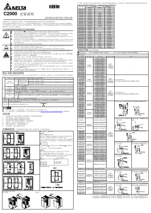
VFD-C2000 安装说明 100312
73 [124]
150C23A
166 [282]
12 [20]
178 [302]
185C23A
166 [282]
12 [20]
178 [302]
220C23A
146 [248]
12 [20]
158 [268]
300C23A
179 [304]
30 [51]
209 [355]
370C23A
179 [304]
下。
包装落下
贮藏/运输 ISTA 程序 1A(根据重量) IEC60068-2-31
震动 1.0mm,峰-峰值从 2~13.2Hz;0.7G~1.0G,从 13.2~55Hz;1.0G,从 55~512Hz; 符合 IEC 60068-2-6
冲击 符合 IEC/EN 60068-2-27
操作位置 正常安装位置时最大容许偏移角度为±10°
30 [51]
209 [355]
450C23A
228 [387]
73 [124]
301 [511]
550C23A
228 [387]
73 [124]
301 [511]
750C23A
246 [418]
73 [124]
319 [542]
022C43A/E
14 [24]
-
14 [24]
037C43A/E
10 [17]
20 100 3-15
/ind ustrialautomation/
C2000 安装说明
50 116 8860 1- 2 CQ1
高阶磁场向量控制泛用驱动器
请在装机之前,详细阅读本产品说明,并请妥善保存随机附赠之光盘内容及交由该机器的使用者。 交流马达驱动器乃精密的电力电子产品,为了操作者及机械设备的安全,请务必交由专业的电机工程人员安装试车及调整参数, 本产品说明中有 [ 危险 ]、[ 注意 ]等符号说明的地方,请务必仔细研读,若有任何疑虑的地方请连络本公司各地的代理商洽询, 我们的专业人员会乐于为您服务。
台达C2000闭环转矩调机步骤
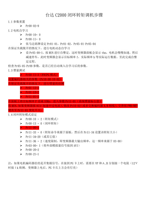
台达C2000闭环转矩调机步骤1.1参数重置➢Pr00-02=91.2电机自学习➢Pr00-10= 0➢Pr00-11= 0➢依马达铭牌设定Pr01-01,Pr01-02,Pr05-01~Pr05-04在保证负载脱开的情况下,进行电机动态自学习➢设Pr05-00=1,按RUN进行自整定,这时变频器面板会显示thn,电机会慢慢加速,然后减速停车,此时变频器会显示目标频率f,实际频率h等实际运行数据。
至此完成自整定过程。
检查Pr05-05~Pr09参数,是否已经自动填入自学习后的参数。
1.3惯量测试➢Pr00-11=3(FOCPG模式)设置编码器相关的参数(Pr10-00~10-02)在保证负载脱开的情况下,进行惯量的估测➢Pr01-12=2➢Pr01-13=2➢Pr11-01=2在面板上将目标频率F设成33Hz,进入参数Pr11-01(系统惯量标么值)按RUN,如果变频器报OCA(加速中过电流),修改Pr10-02(或者交换编码器A,B相线),交替按FWD/REV 键直至Pr11-01变化不大。
1.4闭环转矩模式设定➢Pr00-10 = 2(转矩模式)➢Pr00-13 = 0(闭环转矩)➢Pr11-00=1➢Pr11-33 = 0(转矩命令来源于面板,然后在Pr11-34设置该转矩大小)➢Pr11-34=20(或其它值)➢Pr11-36 = 2(速度限制,即变频器最大输出频率,这一频率来源于03-00)➢Pr03-00= 1(将外部模拟量信号接到AVI)➢Pr00-20=2➢Pr00-21=1注:如果电机编码器给的是开集极信号,在接到PG卡上时,需要在VP和A,B分别接一个电阻(12V时接1k欧姆,变频器上电后,PG卡右上方会有灯亮)。
C2000 C2100 ORP pH 控制器所有者指南说明书

C2000/C2100 ORP/pH Controllers 120V/240VIMPORTANT SAFETY INFORMATION When installing and using this electrical equipment, basic safety precautions should always be followed including the following:READ AND FOLLOW ALL INSTALLATION INSTRUCTIONS.Installation of this equipment should be performed by a licensed electrician and conform to all National Electric Code (NEC), state and local codes.Installations in Canada must complyto CEC requirements.WARNING:To reduce the risk of electrical shock:•Turn off or disconnect the power source before installing,opening the door, or adjusting the internal workings ofthe controller.•Install all electrical equipment at least 10 feet (3 m) frominside wall of pool or spa.•Connect this device only to a grounding-type receptacleprotected by a ground-fault circuit interrupter (GFCI).•Do not use an extension cord, connect the controllerdirectly into the outlet.Do not bury the cord. WARNING:To reduce risk of injury, do not permit children to use this product unless they are closely supervised at all times.For proper operation, it is imperative that the system has proper flow past the sensors when the pool filtration system is running. When automating a body of water, size the feeders so desired levels can be attained in short operating cycles.If feeders are unable to keep up with demand within a short time frame, automation becomes ineffective.While the system is feeding, inaccurate sanitizer/pH levels may be displayed because the system is still circulating the chemical.Observe precautions for electrostaticsensitive devices.SAVE THESE INSTRUCTIONS.Table of ContentsSpecificationsIntroduction . . . . . . . . . . . . . . . . . . . . . . . . . . . . . . . . . . . . . . . . .2 Components . . . . . . . . . . . . . . . . . . . . . . . . . . . . . . . . . . . .2 Installation . . . . . . . . . . . . . . . . . . . . . . . . . . . . . . . . . . . . . . . . . .4 Feed Systems . . . . . . . . . . . . . . . . . . . . . . . . . . . . . . . . . . .4 Controller . . . . . . . . . . . . . . . . . . . . . . . . . . . . . . . . . . . . . . .6 Flow Cell/Flow Switch Assembly . . . . . . . . . . . . . . . . . . . . .6 Sensor . . . . . . . . . . . . . . . . . . . . . . . . . . . . . . . . . . . . .10 Electrical Connections . . . . . . . . . . . . . . . . . . . . . . . . . . . .10 Adding a Second Controller . . . . . . . . . . . . . . . . . . . . .13 System Setup . . . . . . . . . . . . . . . . . . . . . . . . . . . . . . . . . . . . . .14 Controller Display Overview . . . . . . . . . . . . . . . . . . . . . . .15 Display Symbols . . . . . . . . . . . . . . . . . . . . . . . . . . . . . .15Navigating the System . . . . . . . . . . . . . . . . . . . . . . . . .16 Setup Screen . . . . . . . . . . . . . . . . . . . . . . . . . . . . . . . . . . .17 Watermatic #1 Screen . . . . . . . . . . . . . . . . . . . . . . . . . . . .18 ORP Setup Screen . . . . . . . . . . . . . . . . . . . . . . . . . . . . . .19 PH Setup Screen . . . . . . . . . . . . . . . . . . . . . . . . . . . . . . . .21 Operation . . . . . . . . . . . . . . . . . . . . . . . . . . . . . . . . . . . . . . . . .23 Standby Mode . . . . . . . . . . . . . . . . . . . . . . . . . . . . . . . . . .23 Command Center Setup Screen . . . . . . . . . . . . . . . . . . . .24 Maintenance . . . . . . . . . . . . . . . . . . . . . . . . . . . . . . . . . . . . . . .25 Cleaning the Sensor Tips . . . . . . . . . . . . . . . . . . . . . . . . .25 Checking the ORP Sensor . . . . . . . . . . . . . . . . . . . . . . . .25 Checking the pH Sensor . . . . . . . . . . . . . . . . . . . . . . . . . .26 Winterizing . . . . . . . . . . . . . . . . . . . . . . . . . . . . . . . . . . . . .26 Warranty . . . . . . . . . . . . . . . . . . . . . . . . . . . . . . . . . . . . . . . . . .27 Appendix . . . . . . . . . . . . . . . . . . . . . . . . . . . . . . . . . . . . . . . . . .29SpecificationspH Control Range:7.0 to 8.0ORP Control Range:200 to 900Input Power:•120 VAC 50/60 Hz auto-switching whensupplied with 3-wire grounded powercord;GFCI source required.•240 VAC 50/60 Hz capable. Controller Power: 1 amp, internally fused.Output Power:•120 VAC 50/60 Hz auto-switching whensupplied with 3-wire grounded powercord;GFCI source required.•240 VAC 50/60 Hz capable.•8A fuse for 120V, 4A fuse for 240V.• 3 HP (High power - line voltage) and2 LP (Low power - 24V) built-in relays Display:Graphic, LCD, menu-drivenOperating T emp:40 - 120°FSensors:pH:glass combination with 10' cableORP:platinum combination w/ 10' cable Inputs:•Polaris CPC cable with 9-pin connectorORP & pH sensors:BNC connectorLevel detection:allows feeding, normallyclosed.Flow detection;allows feeding,normally closedOutputs:•ORP Feeder - High Voltage120 VAC 50/60 Hz (with 120V input)240 VAC 50/60 Hz;(with 240V input)8A on-board fuse for 120, 4A fuse for240, normally OFF.•ORP Feeder – Low Voltage, 24V•pH Feeder – High Voltage,120 VAC 50/60 Hz (with 120V input)240 VAC 50/60 Hz;(with 240V input)8A on-board fuse for 120, 4A fuse for240, normally OFF.•pH Feeder – Low Voltage, 24V•RS232 for dataSystem SetupDo not add chemicals to the feeders until completing the following start-up operations.e a DPD test kit to test the water, then manually adjustand balance the pool to acceptable ranges.It may takeseveral hours for the levels to stabilize.2.With the controller power OFF, turn on the filter pumpand check for leaks in the system and flow throughthe flow cell.3.Plug in or supply power to the controller.The C2000 displaywill illuminate showing the Setup screen or, if a C2100 isinstalled with an Eos system, the Watermatic Control screen will become available on the Eos display.To adjust the brightness or contrast of the display, pressthe left and right arrow keys simultaneously to open theCommand Center Setup screen.Review the ControllerDisplay Overview section and adjust settings as necessary.4.T o set up the system:•Get familiar with the screen displays and navigatingthe system.•Complete controller configurationOverfeedSets a maximum time for the ORP to reach the set point.If the set point is not reached, the feeder shuts-down and an alert is ed only when Feed Time = Continuous, it replaces the Delay Time option on the display.SetpointSets the desired level of ORP.Set between 200 and 900 in increments of 10.The default is 650.The controller displays direct ORP readings and the control is based on this, not the parts per million (ppm).While ORP indicates the effectiveness of the sanitizer, it does not directly correlate to a ppm e a DPD test kit to measure the free chlorine.If more or less sanitizer is needed, adjust the set point up or down accordingly.Also note the ORP reading is not linear.An adjustment from 700 to 750 could increase the sanitizer level by several ppm.The World Health Organization recommends an ORP at or above 650.High AlertSpecifies the high end of the acceptable ORP range.Set between 650 and 950, in increments of 10, at least 100 greater than the set point (if set point 850, High Alert = 950).The default of 900 should be appropriate for most applications.Low AlertSpecifies the low end of the acceptable ORP range.Set between 100 and 640, in increments of 10, at least 100 below the set point.The default of 100 is usually appropriate.Wait for pHY es = ORP will not feed at the same time as the pH.The pH will always feed first.Preventing simultaneous feeding effectively reduces current draw on the GFCI circuit.No = ORP can feed at same time as pH.Default = Y es.Stop for pHY es = ORP will not feed if the pH is out of range.If the pH goes back in range, the alert clears itself and ORP can feed.No = ORP is allowed to feed regardless of pH.Default = Y es.Next CleaningSets a date (month and day) for the next sensor cleaning.Simply a reminder display.Default = OFF.Feed TimeDesignates how long the feeder is activated.Delay TimeSets the amount time between feeding.Not shown when “Continuous”feed is selected.OverfeedUsed only with “Continuous”feed.if the pH does not reach the set point within the specified time, the feeder shuts-down and an alert is signaled.SetpointSet between 7.0 and 8.2 in increments of 0.1 pH.Default is 7.5. High AlertSpecifies the high end of the acceptable pH range.Set between 7.5 and 8.4 pH, in increments of 0.1 pH,at least 0.4 greater than the set point (if Setpoint 8.0, High Alert = 8.4).The default of 8.4 will be appropriate for most applications.Low AlertSpecifies the low end of the acceptable pH range.Set between 6.8 and 7.4 pH, in increments 0.1 pH, at least 0.4 less than the set point (if Setpoint 7.2, Low Alert = 6.8).The default of 6.8 will usually be appropriate.Next CleaningSets a date (month and day) for next sensor cleaning.Simply a reminder display, the factory default setting is OFF.Next CalibrationSets a date (month and day) for next sensor calibration.Simply a reminder display, the factory default setting is OFF. CalibrationAllows user to adjust the pH sensor reading to match the actual pH of the water.Always use water from the sample port of the flow cell to obtain the pH reading for calibration.Since the pH sensor can drift slightly over time and the calibration will offset this drift, calibrate the sensor at least once a month.Cursor ControlItem SelectMaintenanceCleaning the Sensor TipsClean sensors once a month to ensure accurate readings.When dirty, the sensors can read a lower than actual sanitizer/pH level and can cause too much sanitizer/pH to be dispensed.Note:A sensor tip coated with calcium scale will not look dirty. To clean the sensor tip.1.T urn off the controller.Turn off the filtration system or closethe valves to isolate the flow cell.2.Loosen the compression-fitting nut and remove the sensorfrom the flow cell assembly.3.Swirl the tip for five seconds in muriatic acid (diluted 5 to 1)or white vinegar, and rinse it in water.Do not touch, wipe or brush the end of the sensor.For commercial pools and spas, every third cleaning, swirl the sensor tip in a solution of liquid soap and water.Rinse with water.4.Reposition the sensor in the flow cell assembly and turn onthe controller.5.Allow the controller to operate for a few minutes to get anaccurate reading.Adjust the setting if necessary.Checking the ORP SensorThe ORP sensor should be checked every six months or anytime the feeder oversanitizes the water.1.Clean the sensor tip.2.Put the sensor in a clean glass of tap water.This shouldgive a reading of between 200 and 400.Adding a pinch ofDichlor or T richlor should cause the ORP level to jumpto between 750 and 800.If Dichlor or Trichlor are notavailable and a sanitizer with a high pH such as calciumhypochlorite or liquid chlorine (sodium hypochlorite) is used, the ORP level may only rise to between 650 and 750.3.If the sensor does not respond as indicated, the sensorshould be replaced.Checking the pH SensorThe pH sensor should be checked every six months or anytime the pH goes out of range.1.Clean the sensor.2.Place the sensor in a clean glass of tap water.Add a smallamount of acid to the glass.The pH reading should drop.Place the sensor in any solution with a pH above 7.5.ThepH reading should rise.3.If the sensor does not respond as indicated, the sensorshould be replaced.WinterizingIf the system is located in colder climates, it is important to winterize the system.1.T urn off the main power to the controller.2.Gently remove the sensors from the flow cell assembly andstore them in a protective cap or bottle filled with a liquidsolution of one teaspoon salt and three teaspoons water.Mix the solution thoroughly and make sure it completely covers the tip of the sensors.Store the sensors in a warm place.Do not expose sensors to freezing temperatures.3.Drain the water from the flow cell/flow switch assembly.WarrantyPolaris Watermatic C2000/C2100 ORP/pH ControllerThis limited warranty is extended to the original consumer purchaser of this Polaris Watermatic Controller manufactured by Polaris Pool Systems, Inc.("Polaris"), 2620 Commerce Way, Vista, CA 92081-8438, USA.Polaris warrants the Watermatic Controller, including all parts and components thereof, to be free of defects in material and workmanship.For questions regarding your Polaris Watermatic Controller, please call or write us.Be sure to provide the serial number of your unit.The warranty commences on the date of installation of the controller and shall remain in effect for a period of one (1) year from the date of purchase as established by proof of purchase or two (2) years from the date of manufacture of the controller as established by the serial number, whichever is earlier.This limited warranty does not apply if the failure is caused or contributed by any of the following:improper handling, improper storage, abuse, unsuitable application of the unit, lack of reasonable and necessary maintenance, winter freezing or repairs made or attempted by other than Polaris or one of its Authorized Service Centers.Polaris will repair or replace, at its option, a unit, part or component proved to be defective within the warranty period and under the conditions of the warranty. Unless local repair is authorized, the consumer must deliveror ship the unit or the warranted parts or components, freight prepaid to the nearest Polaris Authorized Service Center or return it freight prepaid (after proper authorization) to the plant of manufacture.Authorization to return a unit to the plant of manufacture must be obtained from the Polaris Customer Service Department.For your convenience, please check with your dealer for the local procedure before exercising this warranty.If further directions or instructions should be required, contact the Customer Service Department at 1-800-822-7933 (USA and Canada only) or 760-599-9600.Be sure to insure shipments against loss or damage during transit.Polaris is not responsible for the cost of removal of the unit, damages occurring during removal or due to removal, any other expenses incurred in shipping the unit or parts to or from the factory or its Authorized Service Centers, or the installation of the repaired or replacement unit.The consumer must bear these expenses.This warranty does not cover repair of a unit except at our factory or a Polaris Authorized Service Center.REP AIR OR REPLACEMENT AS PROVIDED UNDER THIS LIMITED WARRANTY IS THE EXCLUSIVE REMEDY OF THE CONSUMER.THIS LIMITED WARRANTY IS IN LIEU OF ALL OTHER WARRANTIES, EXPRESS OR IMPLIED, INCLUDING THE IMPLIED WARRANTIES OF MERCHANTABILITY AND FITNESS FOR A PARTICULAR PURPOSE, AND ALL SUCH OTHER WARRANTIES ARE DISCLAIMED EXCEPT TO THE EXTENT ANY IMPLIED WARRANTY MAY BE IMPOSED BY STA TE CONSUMER LAW.ANY SUCH IMPLIED WARRANTY IMPOSED BY ST ATE CONSUMER LAW IS LIMITED INDURA TION TO ONE (1) YEAR FROM DATE OF PURCHASE. IN NO EVENT SHALL POLARIS BE LIABLE FOR INCIDENT AL OR CONSEQUENTIAL DAMAGES OF ANY NA TURE OR KIND OR FOR DAMAGES TO PERSONS OR PROPERTY, INCLUDING ANY DAMAGE RESULTING FROM THE USE OF THE POLARIS WATERMA TIC CONTROLLER.THE ONL Y REMEDY PROVIDED TO YOU UNDER AN APPLICABLE IMPLIED WARRANTY AND THE LIMITED WARRANTY SET FORTH ABOVE SHALL BE THE REMEDIES EXPRESSL Y PROVIDED FOR UNDER THIS LIMITED WARRANTY.This limited warranty gives you specific legal rights.Y ou may also have other rights that may vary from state to state.Some states do not allow limitations on how long an implied warranty lasts, or the exclusion or limitation of incidental or consequential damages, so the above limitations may not apply to you.This limited warranty is valid only in the United Statesof America and Canada, and it does not apply to Polaris Watermatic Controllers sold or installed in any other country.AppendixFeed Times and Delay TimesThe default feeding mode for the controller is continuous feed. However, when the ORP or pH feeder type is specified during setup, the Feed Time and Delay Time defaults change to the feeder specific defaults listed below.The listed options are also available and the ORP and pH sides of the controller can be modified independently.After allowing the system to run for a few days, adjust the ORP and/or pH settings as needed.Lengthen the feed cycle if the water is undersanitized or shorten it if the water is oversanitized. Shorten the delay time if the feeder cannot keep up with demand. Granular FeederFeed Time Delay Time Overfeed(Min.)(Min.) Options 0.5, 1, 2, 3, 4, 5 Sec. 1 – 99OffDefaults 5 Sec.10 min OffLiquid Feeder(Use for Ozone Generators)Feed Time Delay Time Overfeed(Min.)(Min.) Options Continuous Off 1 - 995, 10, 15, 20, 30 Sec. 1 - 99Off1, 2, 3, 4, 5, 10, 15 Min.Defaults10 Min.10 min OffErosion FeederFeed Time Delay Time Overfeed(Min.)(Min.) Options:Continuous Off 1 - 995, 10, 15, 20, 30 Sec. 1 - 99Off1, 2, 3, 4, 5, 10, 15 Min.Default 10 Min.10 min OffErosion LP = Low power (24V) solenoidErosion HP = High power (line voltage) solenoidAlerts and AlarmsThe following alert conditions will sound the audible alarm:•WM 1 High PH Alert•WM 1 Low PH Alert•WM 1 High ORP Alert•WM 1 Low ORP Alert•WM 1 PH Overfeed•WM 1 ORP Overfeed•WM 1 Feeder Empty (if Level Switch is selected.) Each of these alerts are also present on the second controller (Watermatic #2 or WM 2) if one is added to the system.The following alert conditions will not sound the Alarm:•WM 1 No Flow•WM 1 2-Minute Flow Delay•WM 1 Clean PH Sensor•WM 1 Cal PH Sensor•WM 1 Clean ORP SensorAgain, these alerts are present on the additional controller (Watermatic #2 or WM 2) if it is added to the systemSalt ChlorinatorFeed TimeDelay Time Overfeed (Min.)(Hrs.)Options ContinuousOff Off, 4, 8,12, 24 hrs Defaults Continuous Off 12 hrs。
- 1、下载文档前请自行甄别文档内容的完整性,平台不提供额外的编辑、内容补充、找答案等附加服务。
- 2、"仅部分预览"的文档,不可在线预览部分如存在完整性等问题,可反馈申请退款(可完整预览的文档不适用该条件!)。
- 3、如文档侵犯您的权益,请联系客服反馈,我们会尽快为您处理(人工客服工作时间:9:00-18:30)。
台达变频器C2000使用说明
当用户拿到产品机种时,请参考下列步骤,以确保使用安全。
1)打开包装后,先确认产品是否因运送途中有所损坏。
检查并确定印在外箱及机身的铭牌标签,是否相符合。
2)确认配线是否适用符合该交流马达驱动器的电压范围。
安装交流马达驱动器时,请参照安装手册内容说明进行安装。
3)连接电源前,请先确认连接电源、马达、控制板、操作面板等等,是否装置确定。
4)交流马达驱动器在进行配线时,请留意输入端子『R/L1、S/L2、T/L3』与输出端子『U/T1、V/T2、W/T3』接线位置,请勿接错端子以避免造成机器损坏。
5)通电后,藉由数字操作器(KPC-CC01)可自由选择语言、设定各参数群。
先以低频率试运转,慢慢调高频率到达指定的速度。
检查&建议
❒请勿让各种纤维、纸片、木片(屑)或金属碎块等异物进入交流马达驱动器内或粘附于散热风扇上。
❒应安装于如金属等不会燃烧的控制盘中,否则容易发生火灾事故。
❒交流马达驱动器应该安装符合污染等级 2 之环境与干净循环空气。
干净循环空气定义为无污染物质以及具电子污染粉尘物质之气体
接线方式
打开交流马达驱动器上盖后,露出各接线端子排,检查各主回路电路及控制回路电路之端子是否标示清楚及接线时注意以下各项说明,千万不要接错线。
❒交流马达驱动器的主回路电源端子 R/L1、S/L2、T/L3 是输入电源端。
如果将电源错误连接于其它端子,则将损坏交流马达驱动器。
另外应确认电源应在铭牌标示的允许电压/电流范围内(参考 1-1 产品外观之铭牌说明)。
❒接地端子必须良好接地,一方面可以防止雷击或感电事故,另外能降低噪声干扰。
❒各连接端子与导线间的螺丝请确实锁紧,以防震动松脱产生火花。
❒若要改变接线,首先应关掉运转的变频器电源,因为内部回路直流部分滤波电容器完成放电需要一定时间。
为避免危险,客户可使用直流电压表作测试。
确认电压值小于 25Vdc 安全电压值后,才能开始进行配线。
若使用者未让变频器充分时间放电,内部会有残留电压,此时进行配线会造成电路短路并发生火花现象,所以请用户最好在无电压条件下进行作业以确保自身安全。
❒配线作业应由专业人员进行。
确认电源断开(OFF)后才可作业,否则可
能发生感电事故。
❒配线时,配线线径规格之选定,请依照电工法规之规定施行配线,以策安全。
❒完成电路配线后,请再次检查以下几点:
1.所有连接是否都正确无误?
2.有无遗漏接线?
3.各端子和连接线之间是否有短路或对地短路?
接线图
主回路端子
成都永浩机电工程技术有限公司是台达产品经销商,专注于自动化过程控制,现场仪表设计、销售服务的现代化高新技术企业,公司引进德国先进的技术,开发艾拓利尔品牌系列流量、液位、压力产品,长期与德国许多大型仪表企业技术合作,产品不断更新换代,自投入市场以来,广泛应用于石油、化工、电力、冶金、环保、制药、水处理等行业,得到了广大用户的一致好评。
公司主要产品包括:
流量仪表类:电磁流量计、涡街流量计、涡轮流量计、差压式流量计、超声波流量计、金属管浮子流量计、椭圆齿轮流量计、质量流量计及热式流量开关。
物位仪表类:压阻式液位变送器、电容式液位变送器、超声波液位计、雷达物位计等。
压力类仪表:压力变送器、差压变送器等。
工控类产品:西门子、台达、施耐德、罗克韦尔系列PLC,人机界面,伺服电机,变频器,工控机,成套系统集成。
