NACE0.22M4.0V6.3X5.5TR13F中文资料
三极管参数中文与英文对照(精)

三极管参数中文与英文对照(精)电阻模型参数R 电阻倍率因子TC1 线性温度系数TC2 二次温度系数电容模型参数C 电容倍率因子VC1 线性电压系数VC2 二次电压系数TC1 线性温度系数TC2 二次温度系数电感模型参数L 电感倍率因子IL1 线性电流系数IL2 二次电流系数TC1 线性温度系数TC2 二次温度系数二极管模型参数IS 饱和电流RS 寄生串联电阻N 发射系数TT 渡越时间CJO 零偏压 PN 结电容VJ PN 结自建电势M PN 结剃度因子EG 禁带宽度XT1 IS 的温度指数FC 正偏耗尽层电容系数BV 反向击穿电压(漆点电压 IBV 反向击穿电流(漆点电流 KF 闪烁躁声系数AF 闪烁躁声指数双极晶体管(三极管IS 传输饱和电流EG 禁带宽度XTI (PT IS 的温度效应指数 BF 正向电流放大系数NF 正向电流发射系数V AF (V A 正向欧拉电压IKF (IK 正向漆点电流ISE (C2 B-E 漏饱和电流NE B-E 漏饱和电流BR 反向电流放大系数NR 反向电流发射系数V AR (VB 正想欧拉电压IKR 反向漆点电流ISC C4 B-C 漏饱和电流NC B-C 漏发射系数RB 零偏压基极电阻IRB 基极电阻降致 RBM/2时的电流RE 发射区串联电阻RC 集电极电阻CJE 零偏发射结 PN 结电容VJE PE 发射结内建电势MJE ME 集电结剃度因子CJC 零偏衬底结 PN 结电容VJC PC 集电结内建电势MJC MC 集电结剃度因子XCJC Cbe 接至内部 Rb 的内部CJS CCS 零偏衬底结 PN 结电容VJS PS 衬底结构 PN 结电容MJS MS 衬底结剃度因子FC 正偏势垒电容系数TF 正向渡越时间XTF TF 随偏置变化的系数VTF TF 随 VBC 变化的电压参数ITF 影响 TF 的大电流参数PTF 在 F=1/(2派 TF Hz 时超前相移 TR 反向渡越时间XTB BF 和 BR 的温度系数KF I/F躁声系数AF I/F躁声指数Is=14.34f 反向饱和电流。
NACE0.22K6.3V6.3X5.5TR13F中文资料

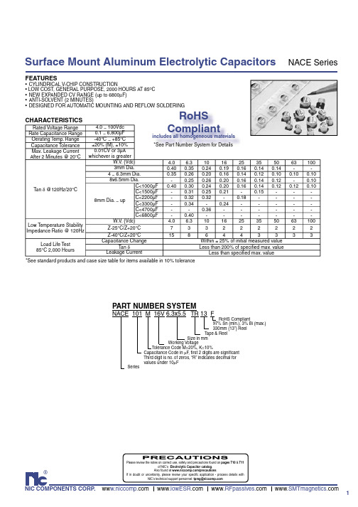
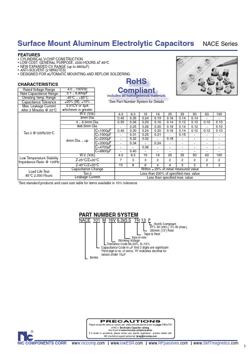
1®NIC COMPONENTS CORP. ww www www www Surface Mount Aluminum Electrolytic CapacitorsNACE SeriesFEATURES•CYLINDRICAL V-CHIP CONSTRUCTION• LOW COST, GENERAL PURPOSE, 2000 HOURS AT 85O C •NEW EXP ANDED CV RANGE (up to 6800µF)•ANTI-SOLVENT (2 MINUTES)•DESIGNED FOR AUTOMATIC MOUNTING AND REFLOW SOLDERINGCHARACTERISTICS*See standard products and case size table for items available in 10% toleranceRated Voltage Range 4.0 ~ 100Vdc Rate Capacitance Range 0.1 ~ 6,800µFOerating Temp. Range -40°C ~ +85°CCapacitance Tolerance ±20% (M), ±10%Max. Leakage Current After 2 Minutes @ 20°C0.01CV or 3µA whichever is greaterTan δ @120Hz/20°C W.V . (Vdc) 4.0 6.31016253550631003mm Dia.0.400.350.240.190.160.140.14--4 ~ 6.3mm Dia.0.350.260.200.160.140.120.100.100.108x6.5mm Dia.-0.250.260.200.160.140.12-0.108mm Dia. ~ upC<1000µF 0.400.300.240.200.160.140.120.120.10C<1500µF -0.310.250.21-0.15---C<2200µF -0.320.32-0.18----C<3300µF -0.34-0.24-----C<4700µF --0.36------C<6800µF -0.40-------Low Temperature StabilityImpedance Ratio @ 120HzW.V . (Vdc) 4.0 6.3101625355063100Z-25°C/Z+20°C 733222222Z-40°C/Z+20°C 1586443333Load Life Test85°C 2,000 HoursCapacitance Change Within ± 25% of initial measured valueTan δLess than 200% of specifi ed max. valueLeakage Current Less than specifi ed max. value NACE 101 M 16V 6.3x5.5 TR 13 FRoHS Compliant97% Sn (min.), 3% Bi (max.) 330mm (13”) Reel Tape & Reel Size in mm Working VoltageTolerance Code M=20%, K=10% Capacitance Code in µF , fi rst 2 digits are signifi cant Third digit is no. of zeros, “R” indicates decimal for values under 10µF SeriesPART NUMBER SYSTEMRoHSCompliantincludes all homogeneous materials *See Part Number System for Details PRECAUTIONSPlease review the notes on correct use, safety and precautions found on pages T10 & T11of NIC’s Electrolytic Capacitor catalog . Also found at /precautionsIf in doubt or uncertainty, please review your specifi c application - process details withNIC’s technical support personnel: tpmg@2MAXIMUM RIPPLE CURRENT O MAXIMUM ESRO Surface Mount Aluminum Electrolytic CapacitorsNACE SeriesSTANDARD PRODUCT AND CASE SIZE TABLE DφxL (mm)*Items available in optional 10% toleranceSurface Mount Aluminum Electrolytic Capacitors NACE Series+ -3。
NACE680M63V10X8TR13F中文资料
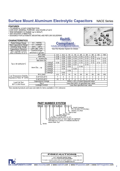
1®NIC COMPONENTS CORP. ww www www www Surface Mount Aluminum Electrolytic CapacitorsNACE SeriesFEATURES•CYLINDRICAL V-CHIP CONSTRUCTION• LOW COST, GENERAL PURPOSE, 2000 HOURS AT 85O C •NEW EXP ANDED CV RANGE (up to 6800µF)•ANTI-SOLVENT (2 MINUTES)•DESIGNED FOR AUTOMATIC MOUNTING AND REFLOW SOLDERINGCHARACTERISTICS*See standard products and case size table for items available in 10% toleranceRated Voltage Range 4.0 ~ 100Vdc Rate Capacitance Range 0.1 ~ 6,800µFOerating Temp. Range -40°C ~ +85°CCapacitance Tolerance ±20% (M), ±10%Max. Leakage Current After 2 Minutes @ 20°C0.01CV or 3µA whichever is greaterTan δ @120Hz/20°C W.V . (Vdc) 4.0 6.31016253550631003mm Dia.0.400.350.240.190.160.140.14--4 ~ 6.3mm Dia.0.350.260.200.160.140.120.100.100.108x6.5mm Dia.-0.250.260.200.160.140.12-0.108mm Dia. ~ upC<1000µF 0.400.300.240.200.160.140.120.120.10C<1500µF -0.310.250.21-0.15---C<2200µF -0.320.32-0.18----C<3300µF -0.34-0.24-----C<4700µF --0.36------C<6800µF -0.40-------Low Temperature StabilityImpedance Ratio @ 120HzW.V . (Vdc) 4.0 6.3101625355063100Z-25°C/Z+20°C 733222222Z-40°C/Z+20°C 1586443333Load Life Test85°C 2,000 HoursCapacitance Change Within ± 25% of initial measured valueTan δLess than 200% of specifi ed max. valueLeakage Current Less than specifi ed max. value NACE 101 M 16V 6.3x5.5 TR 13 FRoHS Compliant97% Sn (min.), 3% Bi (max.) 330mm (13”) Reel Tape & Reel Size in mm Working VoltageTolerance Code M=20%, K=10% Capacitance Code in µF , fi rst 2 digits are signifi cant Third digit is no. of zeros, “R” indicates decimal for values under 10µF SeriesPART NUMBER SYSTEMRoHSCompliantincludes all homogeneous materials *See Part Number System for Details PRECAUTIONSPlease review the notes on correct use, safety and precautions found on pages T10 & T11of NIC’s Electrolytic Capacitor catalog . Also found at /precautionsIf in doubt or uncertainty, please review your specifi c application - process details withNIC’s technical support personnel: tpmg@2MAXIMUM RIPPLE CURRENT O MAXIMUM ESRO Surface Mount Aluminum Electrolytic CapacitorsNACE SeriesSTANDARD PRODUCT AND CASE SIZE TABLE DφxL (mm)*Items available in optional 10% toleranceSurface Mount Aluminum Electrolytic Capacitors NACE Series+ -3。
NSPE470M6.3V8X10.8TR13F中文资料
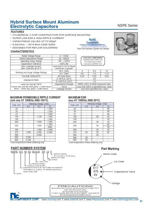
51®NIC COMPONENTS CORP. www www www ww Hybrid Surface Mount Aluminum Electrolytic CapacitorsNSPE SeriesPart MarkingCapacitance ValueVoltageLot CodeSeries Code4704VE17CHARACTERISTICSFEATURES• CYLINDRICAL V-CHIP CONSTRUCTION FOR SURFACE MOUNTING • SUPER LOW ESR & HIGH RIPPLE CURRENT• CAPACITANCE VALUES UP TO 820µF• 6.3x6.3mm ~ 10x10.8mm CASE SIZES• DESIGNED FOR REFLOW SOLDERING LOW ESR COMPONENT HYBRID ELECTROLYTEFor Performance Data see NSPE 471 M 4V 8x10.8 TR 13 FRoHS Compliant97% Sn (min.), 3% Bi (max.) 330mm (13”) Reel Tape & Reel Size in mm Working Voltage Tolerance Code M=20% Capacitance Code in µF, fi rst 2 digits are signifi cant Third digit is no. of zeros, “R” indicates decimal for values under 10µF SeriesPART NUMBER SYSTEMCap. (µF)Working Votage (Vdc)4.0 6.31022--1,02033--1,02047--1,020100-1,1201,550150--1,550220-1,5501,550330-1,5501,550*2090390-1,5502,0904701,5502,0902,090*560-2,090-6802,090--8202,180--Cap. (µF)Working Votage (Vdc)4.0 6.31022--6033--6047--60100-5030150--30220-3030330-3030*25390-3025470302525*560-25-68025--82023--MAXIMUM PERMISSIBLE RIPPLE CURRENT(mA rms AT 100KHz AND 105O C)MAXIMUM ESR(m Ω AT 100KHz AND 20O C)PRECAUTIONSPlease review the notes on correct use, safety and precautions found on pages T10 & T11of NIC’s Electrolytic Capacitor catalog . Also found at /precautionsIf in doubt or uncertainty, please review your speci fi c application - process details withNIC’s technical support personnel: tpmg@Rated Voltage Range4 ~ 10VdcRated Capacitance Range 22 ~ 820µFOperating Temp. Range -55 ~ +105°C Capacitance Tolerance ±20% (M)Max. Leakage Current After 2 Minutes @ 20°C Less than 0.1CV or 50µA whichever is greaterWorking and Surge Voltage RatingsW.V. (Vdc)4 6.310S.V. (Vdc) 4.67.211.5Tan δ @ 120Hz/20°C All Case Sizes 0.240.220.20Impedance RatioZ -55°C/Z +20°C 2.5Z +105°C/Z +20°C 1.0Load Life Test @ 105°C6.3mm Dia. and All 4Vdc parts = 1,000 Hours 8mm ~ 10mm Dia. parts = 2,000 HoursCapacitance Change Within ±20% of initial measured valueTan δLess than 200% of specifi ed max. value Leakage Current Less than specifi ed max. value*Low temperature refl ow soldering only *Low temperature refl ow soldering only RoHSCompliantincludes all homogeneous materials *See Part Number System for DetailsNSPE SeriesHybrid Aluminum Electrolytic CapacitorsRECOMMENDED REFLOW SOLDERING PROFILE50100150200Time (Seconds)Temperature-Deg.C230B STANDARD PRODUCT AND CASE SIZE TABLE Dφ x L (mm)V-chip SMT Aluminum Electrolytic Capacitors/RSL52。
NACC101K105X6.1TR13F中文资料

14®NIC COMPONENTS CORP. www www www www Rated Voltage Range 6.3 ~ 50Vdc Rate Capacitance Range 0.1 ~ 1,000µF Oerating Temp. Range -40°C ~ +105°C Capacitance Tolerance ±20% (M)Max. Leakage Current After 2 Minutes @ 20°C0.01CV or 3µA whichever is greaterTan δ @120Hz/20°CW.V . (Vdc) 6.31016253550S.V .(Vdc)81320324463Tan δ0.3*0.260.200.160.140.12* 1,000µF is 0.5Load Life Test @ 105°C 4mm ~ 6.mm Dia. 3,000hrs 8mm ~ 10mm Dia. 5,000hrsCapacitance ChangeWithin ± 30% of initial measured value Tan δLess than 300% of specifi ed max. valueLeakage CurrentLess than specifi ed max. valueSurface Mount Aluminum Electrolytic CapacitorsNACC Series• CYLINDRICAL V-CHIP CONSTRUCTION FOR SURFACE MOUNTING • HIGH TEMPERA TURE, EXTEND LIFE (5000 HOURS @ 105°C)• 4X6.1mm ~ 10X10.5mm CASE SIZES • DESIGNED FOR REFLOW SOLDERING CHARACTERISTICSFEATURESNACC 101 M 16V 8X10.5 TR 13 FRoHS Compliant 97% Sn, 3% Bi 330mm (13”) Reel Tape & Reel Size in mm Working VoltageTolerance Code M=20%, K=10% Capacitance Code in mF , fi rst 2 digits are signifi cant Third digit is no. of zeros, “R” indicates decimal for values under 10µF SeriesCap (µF)Working Voltage (Vdc)6.310162535500.1----- 1.00.22----- 2.60.33----- 3.20.47----- 5.01.0-----102.2-----163.3-----164.7----152310--28-28352226-39-554933-43-6557914746-7065-10010071-81130-160220101160--220-330230--238--470--340---1000313-----MAXIMUM PERMISSIBLE RIPPLE CURRENT(mA rms @ 120Hz AND 105°C)RoHS Compliantincludes all homogeneous materials *See Part Number System for DetailsPART NUMBER SYSTEMPRECAUTIONSPlease review the notes on correct use, safety and precautions found on pages T10 & T11of NIC’s Electrolytic Capacitor catalog . Also found at /precautionsIf in doubt or uncertainty, please review your specifi c application - process details withNIC’s technical support personnel: tpmg@15Surface Mount Aluminum Electrolytic CapacitorsNACC SeriesCool Down2550100150200250300Time - SecondsT e m p e r a t u r e °C235+ -。
NACV3R3M400V12.5x14TR13F中文资料
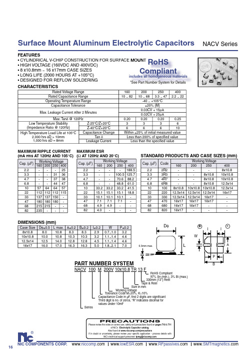
16®NIC COMPONENTS CORP. www www www www .SMTmagnetics.comSurface Mount Aluminum Electrolytic CapacitorsNACV SeriesFEATURES•CYLINDRICAL V-CHIP CONSTRUCTION FOR SURFACE MOUNT •HIGH VOLT AGE (160VDC AND 400VDC)•8 x10.8mm ~ 16 x17mm CASE SIZES •LONG LIFE (2000 HOURS A T +105O C)•DESIGNED FOR REFLOW SOLDERING CHARACTERISTICSDIMENSIONS (mm)CE MOUNT RoHSCompliantincludes all homogeneous materials *See Part Number System for DetailsNACV 100 M 200V 10x10.8 TR 13 FRoHS Compliant97% Sn (min.), 3% Bi (max.) 330mm (13”) Reel Tape & Reel Size in mm Working VoltageT olerance Code M=20%, K=10% Capacitance Code in µF , fi rst 2 digits are signifi cant Third digit is no. of zeros, “R” indicates decimal for values under 10mF SeriesPART NUMBER SYSTEM0.3mm max.D φL+ -IIWPABSTANDARD PRODUCTS AND CASE SIZES (mm)MAXIMUM RIPPLE CURRENT(mA rms AT 120Hz AND 105°C)MAXIMUM ESR (Ω AT 120Hz AND 20°C)Rated Voltage Range 160200250400Rated Capacitance Range 10 ~ 8210 ~ 68 3.3 ~ 47 2.2 ~ 22Operating Temperature Range-40 ~ +105°C Capacitance Tolerance ±20% (M)Max. Leakage Current After 2 Minutes0.03CV + 15µA 0.02CV + 25µAMax. Tan δ @ 120Hz0.200.200.200.25Low Temperature Stability(Impedance Ratio @ 120Hz)Z-25°C/Z+20°C 3336Z-40°C/Z+20°C66610High Temperature Load Life at 105°C2,000 hrs φD > 10mm 1,000 hrs φD = 8mm Capacitance Change Within ±25% of initial measured value Tan δLess than 200% of specifi ed value Leakage CurrentLess than the specifi ed valueCap. (µF)Working Voltage 1602002504002.2---253.3--31364.7--37386.8--444710576464572211211211211533137137150-47180180180-68215215--82235---Cap. (µF)Working Voltage 1602002504002.2---188.53.3--100.5125.74.7--70.688.26.8--48.861.01033.233.233.241.52215.115.115.118.83310.110.110.1-477.17.17.1-68 4.9 4.9--824.0---Cap. (µF)Code Working Voltage1602002504002.22R2---8x10.83.33R3--8x10.810x10.84.74R7--8x10.810x10.86.86R8--8x10.812.5x14101008x10.810x10.810x10.812.5x142222012.5x1412.5x1412.5x1416x173333012.5x1412.5x1416x17-4747016x1716x1716x17-6868016x1716x17--8282016x17---Case Size D φ±0.5L max.A±0.2B±0.2I±0.2W P±0.28x10.88.010.88.38.3 2.90.7~1.0 3.210x10.810.010.810.310.3 3.2 1.1~1.4 4.612.5x1412.514.012.812.8 4.5 1.1~1.4 4.616x1716.017.016.316.35.01.8~2.17.0PRECAUTIONSPlease review the notes on correct use, safety and precautions found on pages T10 & T11of NIC’s Electrolytic Capacitor catalog . Also found at /precautionsIf in doubt or uncertainty, please review your specifi c application - process details withNIC’s technical support personnel: tpmg@元器件交易网。
NACCR47M504X6.1TR13F中文资料
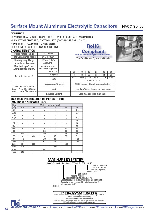
14®NIC COMPONENTS CORP. www www www www Rated Voltage Range 6.3 ~ 50Vdc Rate Capacitance Range 0.1 ~ 1,000µF Oerating Temp. Range -40°C ~ +105°C Capacitance Tolerance ±20% (M)Max. Leakage Current After 2 Minutes @ 20°C0.01CV or 3µA whichever is greaterTan δ @120Hz/20°CW.V . (Vdc) 6.31016253550S.V .(Vdc)81320324463Tan δ0.3*0.260.200.160.140.12* 1,000µF is 0.5Load Life Test @ 105°C 4mm ~ 6.mm Dia. 3,000hrs 8mm ~ 10mm Dia. 5,000hrsCapacitance ChangeWithin ± 30% of initial measured value Tan δLess than 300% of specifi ed max. valueLeakage CurrentLess than specifi ed max. valueSurface Mount Aluminum Electrolytic CapacitorsNACC Series• CYLINDRICAL V-CHIP CONSTRUCTION FOR SURFACE MOUNTING • HIGH TEMPERA TURE, EXTEND LIFE (5000 HOURS @ 105°C)• 4X6.1mm ~ 10X10.5mm CASE SIZES • DESIGNED FOR REFLOW SOLDERING CHARACTERISTICSFEATURESNACC 101 M 16V 8X10.5 TR 13 FRoHS Compliant 97% Sn, 3% Bi 330mm (13”) Reel Tape & Reel Size in mm Working VoltageTolerance Code M=20%, K=10% Capacitance Code in mF , fi rst 2 digits are signifi cant Third digit is no. of zeros, “R” indicates decimal for values under 10µF SeriesCap (µF)Working Voltage (Vdc)6.310162535500.1----- 1.00.22----- 2.60.33----- 3.20.47----- 5.01.0-----102.2-----163.3-----164.7----152310--28-28352226-39-554933-43-6557914746-7065-10010071-81130-160220101160--220-330230--238--470--340---1000313-----MAXIMUM PERMISSIBLE RIPPLE CURRENT(mA rms @ 120Hz AND 105°C)RoHS Compliantincludes all homogeneous materials *See Part Number System for DetailsPART NUMBER SYSTEMPRECAUTIONSPlease review the notes on correct use, safety and precautions found on pages T10 & T11of NIC’s Electrolytic Capacitor catalog . Also found at /precautionsIf in doubt or uncertainty, please review your specifi c application - process details withNIC’s technical support personnel: tpmg@15Surface Mount Aluminum Electrolytic CapacitorsNACC SeriesCool Down2550100150200250300Time - SecondsT e m p e r a t u r e °C235+ -。
NACE68K6.3V10X8TR13F中文资料
1®NIC COMPONENTS CORP. ww www www www Surface Mount Aluminum Electrolytic CapacitorsNACE SeriesFEATURES•CYLINDRICAL V-CHIP CONSTRUCTION• LOW COST, GENERAL PURPOSE, 2000 HOURS AT 85O C •NEW EXP ANDED CV RANGE (up to 6800µF)•ANTI-SOLVENT (2 MINUTES)•DESIGNED FOR AUTOMATIC MOUNTING AND REFLOW SOLDERINGCHARACTERISTICS*See standard products and case size table for items available in 10% toleranceRated Voltage Range 4.0 ~ 100Vdc Rate Capacitance Range 0.1 ~ 6,800µFOerating Temp. Range -40°C ~ +85°CCapacitance Tolerance ±20% (M), ±10%Max. Leakage Current After 2 Minutes @ 20°C0.01CV or 3µA whichever is greaterTan δ @120Hz/20°C W.V . (Vdc) 4.0 6.31016253550631003mm Dia.0.400.350.240.190.160.140.14--4 ~ 6.3mm Dia.0.350.260.200.160.140.120.100.100.108x6.5mm Dia.-0.250.260.200.160.140.12-0.108mm Dia. ~ upC<1000µF 0.400.300.240.200.160.140.120.120.10C<1500µF -0.310.250.21-0.15---C<2200µF -0.320.32-0.18----C<3300µF -0.34-0.24-----C<4700µF --0.36------C<6800µF -0.40-------Low Temperature StabilityImpedance Ratio @ 120HzW.V . (Vdc) 4.0 6.3101625355063100Z-25°C/Z+20°C 733222222Z-40°C/Z+20°C 1586443333Load Life Test85°C 2,000 HoursCapacitance Change Within ± 25% of initial measured valueTan δLess than 200% of specifi ed max. valueLeakage Current Less than specifi ed max. value NACE 101 M 16V 6.3x5.5 TR 13 FRoHS Compliant97% Sn (min.), 3% Bi (max.) 330mm (13”) Reel Tape & Reel Size in mm Working VoltageTolerance Code M=20%, K=10% Capacitance Code in µF , fi rst 2 digits are signifi cant Third digit is no. of zeros, “R” indicates decimal for values under 10µF SeriesPART NUMBER SYSTEMRoHSCompliantincludes all homogeneous materials *See Part Number System for Details PRECAUTIONSPlease review the notes on correct use, safety and precautions found on pages T10 & T11of NIC’s Electrolytic Capacitor catalog . Also found at /precautionsIf in doubt or uncertainty, please review your specifi c application - process details withNIC’s technical support personnel: tpmg@2MAXIMUM RIPPLE CURRENT O MAXIMUM ESRO Surface Mount Aluminum Electrolytic CapacitorsNACE SeriesSTANDARD PRODUCT AND CASE SIZE TABLE DφxL (mm)*Items available in optional 10% toleranceSurface Mount Aluminum Electrolytic Capacitors NACE Series+ -3。
NACEW470K108X10.5TR13F中文资料
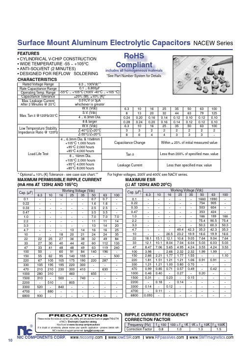
NACEW470K105x5.5TR13F中文资料

For higher voltages, 200V and 400V, see NACV series.
MAXIMUM PERMISSIBLE RIPPLE CURRENT (mA rms AT 120Hz AND 105OC)
Cap. (µF) 0.1 0.22 0.33 0.47 1.0 2.2 3.3 4.7 10 22 33 47 100 150 220 330 470 1000 1500 2200 3300 4700 6800 6.3 22 27 33 50 55 67 105 210 280 310 520 930 10 25 30 41 62 105 195 210 310 510 880 Working Voltage (Vdc) 16 25 35 50 0.7 1.6 2.5 3.5 7.0 11 13 13 14 16 18 20 21 24 27 36 38 32 40 44 42 60 48 48 49 63 60 91 84 140 95 140 155 105 175 190 220 195 220 300 230 300 410 460 655 500 740 805 840 63 0.7 1.6 2.5 3.5 7.0 11 14 16 24 49 112 119 196 287 630 100 7.0 14 20 25 35 84 133 240 500 -
元器件交易网
Surface Mount Aluminum Electrolytic Capacitors
FEATURES • CYLINDRICAL V-CHIP CONSTRUCTION • WIDE TEMPERATURE -55 ~ +105OC • ANTI-SOLVENT (2 MINUTES) • DESIGNED FOR REFLOW ttSOLDERING CHARACTERISTICS
NACV2R2M400V16x17TR13F中文资料

16®NIC COMPONENTS CORP. www www www www .SMTmagnetics.comSurface Mount Aluminum Electrolytic CapacitorsNACV SeriesFEATURES•CYLINDRICAL V-CHIP CONSTRUCTION FOR SURFACE MOUNT •HIGH VOLT AGE (160VDC AND 400VDC)•8 x10.8mm ~ 16 x17mm CASE SIZES •LONG LIFE (2000 HOURS A T +105O C)•DESIGNED FOR REFLOW SOLDERING CHARACTERISTICSDIMENSIONS (mm)CE MOUNT RoHSCompliantincludes all homogeneous materials *See Part Number System for DetailsNACV 100 M 200V 10x10.8 TR 13 FRoHS Compliant97% Sn (min.), 3% Bi (max.) 330mm (13”) Reel Tape & Reel Size in mm Working VoltageT olerance Code M=20%, K=10% Capacitance Code in µF , fi rst 2 digits are signifi cant Third digit is no. of zeros, “R” indicates decimal for values under 10mF SeriesPART NUMBER SYSTEM0.3mm max.D φL+ -IIWPABSTANDARD PRODUCTS AND CASE SIZES (mm)MAXIMUM RIPPLE CURRENT(mA rms AT 120Hz AND 105°C)MAXIMUM ESR (Ω AT 120Hz AND 20°C)Rated Voltage Range 160200250400Rated Capacitance Range 10 ~ 8210 ~ 68 3.3 ~ 47 2.2 ~ 22Operating Temperature Range-40 ~ +105°C Capacitance Tolerance ±20% (M)Max. Leakage Current After 2 Minutes0.03CV + 15µA 0.02CV + 25µAMax. Tan δ @ 120Hz0.200.200.200.25Low Temperature Stability(Impedance Ratio @ 120Hz)Z-25°C/Z+20°C 3336Z-40°C/Z+20°C66610High Temperature Load Life at 105°C2,000 hrs φD > 10mm 1,000 hrs φD = 8mm Capacitance Change Within ±25% of initial measured value Tan δLess than 200% of specifi ed value Leakage CurrentLess than the specifi ed valueCap. (µF)Working Voltage 1602002504002.2---253.3--31364.7--37386.8--444710576464572211211211211533137137150-47180180180-68215215--82235---Cap. (µF)Working Voltage 1602002504002.2---188.53.3--100.5125.74.7--70.688.26.8--48.861.01033.233.233.241.52215.115.115.118.83310.110.110.1-477.17.17.1-68 4.9 4.9--824.0---Cap. (µF)Code Working Voltage1602002504002.22R2---8x10.83.33R3--8x10.810x10.84.74R7--8x10.810x10.86.86R8--8x10.812.5x14101008x10.810x10.810x10.812.5x142222012.5x1412.5x1412.5x1416x173333012.5x1412.5x1416x17-4747016x1716x1716x17-6868016x1716x17--8282016x17---Case Size D φ±0.5L max.A±0.2B±0.2I±0.2W P±0.28x10.88.010.88.38.3 2.90.7~1.0 3.210x10.810.010.810.310.3 3.2 1.1~1.4 4.612.5x1412.514.012.812.8 4.5 1.1~1.4 4.616x1716.017.016.316.35.01.8~2.17.0PRECAUTIONSPlease review the notes on correct use, safety and precautions found on pages T10 & T11of NIC’s Electrolytic Capacitor catalog . Also found at /precautionsIf in doubt or uncertainty, please review your specifi c application - process details withNIC’s technical support personnel: tpmg@元器件交易网。
NACHR22K25V5X6.3TR13F中文资料
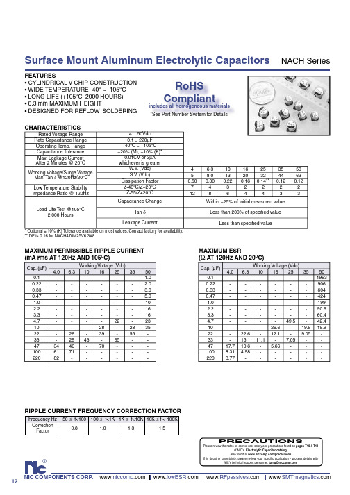
NACH Series
Dφ
L
+
I
I
-
A P B
DIMENSIONS (mm)
Case Size 4 x 6.3 5 x 6.3 6.3 x 6.3 Dφ ±0.5 4.0 5.0 6.3 L max. 6.3 6.3 6.3 A ±0.2 4.3 5.3 6.6 B ±0.2 4.3 5.3 6.6 I ±0.2 1.8 2.2 2.5 W 0.5 ~ 0.8 0.5 ~ 8 0.5 ~ 0.8 P ±0.2 1.0 1.5 2.2
RIPPLE CURRENT FREQUENCY CORRECTION FACTOR
Frequency Hz Correction Factor 50 ≤ f<100 100 ≤ f<1K 1K ≤ f<10K 10K ≤ f < 100K 0.8 1.0 1.3 1.5 PRECAUTIONS
®
Please review the notes on correct use, safety and precautions found on pages T10 & T11 of NIC’s Electrolytic Capacitor catalog. Also found at /precautions If in doubt or uncertainty, please review your specific application - process details with NIC’s technical support personnel: tpmg@
Rated Voltage Range Rate Capacitance Range Operating Temp. Range Capacitance Tolerance Max. Leakage Current After 2 Minutes @ 20°C Working Voltage/Surge Voltage Max. Tan δ @120Hz/20°C Low Temperature Stability Impedance Ratio @ 120Hz Load Life Test @105°C 2,000 Hours 4 ~ 50Vdc 0.1 ~ 220µF -40°C ~ +105°C ±20% (M), ±10% (K)* 0.01CV or 3µA whichever is greater W.V. (Vdc) S.V. (Vdc) Dissipation Factor Z-40°C/Z+20°C Z-55/Z+20°C Capacitance Change Tan δ Leakage Current
NACE680M63V6.3X6.3TR13F中文资料
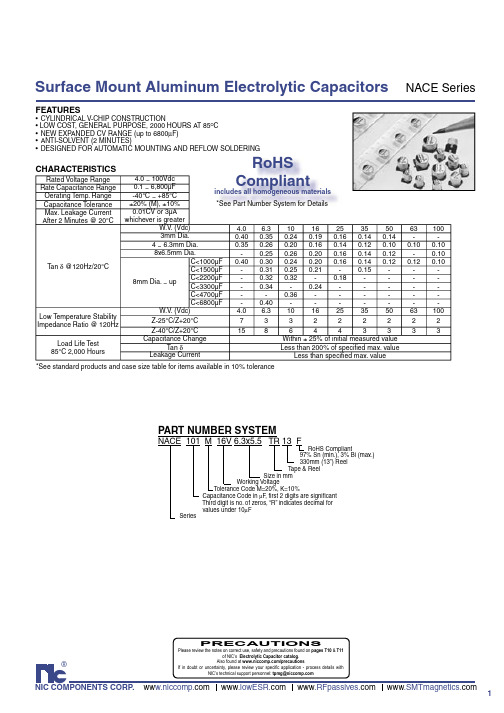
1®NIC COMPONENTS CORP. ww www www www Surface Mount Aluminum Electrolytic CapacitorsNACE SeriesFEATURES•CYLINDRICAL V-CHIP CONSTRUCTION• LOW COST, GENERAL PURPOSE, 2000 HOURS AT 85O C •NEW EXP ANDED CV RANGE (up to 6800µF)•ANTI-SOLVENT (2 MINUTES)•DESIGNED FOR AUTOMATIC MOUNTING AND REFLOW SOLDERINGCHARACTERISTICS*See standard products and case size table for items available in 10% toleranceRated Voltage Range 4.0 ~ 100Vdc Rate Capacitance Range 0.1 ~ 6,800µFOerating Temp. Range -40°C ~ +85°CCapacitance Tolerance ±20% (M), ±10%Max. Leakage Current After 2 Minutes @ 20°C0.01CV or 3µA whichever is greaterTan δ @120Hz/20°C W.V . (Vdc) 4.0 6.31016253550631003mm Dia.0.400.350.240.190.160.140.14--4 ~ 6.3mm Dia.0.350.260.200.160.140.120.100.100.108x6.5mm Dia.-0.250.260.200.160.140.12-0.108mm Dia. ~ upC<1000µF 0.400.300.240.200.160.140.120.120.10C<1500µF -0.310.250.21-0.15---C<2200µF -0.320.32-0.18----C<3300µF -0.34-0.24-----C<4700µF --0.36------C<6800µF -0.40-------Low Temperature StabilityImpedance Ratio @ 120HzW.V . (Vdc) 4.0 6.3101625355063100Z-25°C/Z+20°C 733222222Z-40°C/Z+20°C 1586443333Load Life Test85°C 2,000 HoursCapacitance Change Within ± 25% of initial measured valueTan δLess than 200% of specifi ed max. valueLeakage Current Less than specifi ed max. value NACE 101 M 16V 6.3x5.5 TR 13 FRoHS Compliant97% Sn (min.), 3% Bi (max.) 330mm (13”) Reel Tape & Reel Size in mm Working VoltageTolerance Code M=20%, K=10% Capacitance Code in µF , fi rst 2 digits are signifi cant Third digit is no. of zeros, “R” indicates decimal for values under 10µF SeriesPART NUMBER SYSTEMRoHSCompliantincludes all homogeneous materials *See Part Number System for Details PRECAUTIONSPlease review the notes on correct use, safety and precautions found on pages T10 & T11of NIC’s Electrolytic Capacitor catalog . Also found at /precautionsIf in doubt or uncertainty, please review your specifi c application - process details withNIC’s technical support personnel: tpmg@2MAXIMUM RIPPLE CURRENT O MAXIMUM ESRO Surface Mount Aluminum Electrolytic CapacitorsNACE SeriesSTANDARD PRODUCT AND CASE SIZE TABLE DφxL (mm)*Items available in optional 10% toleranceSurface Mount Aluminum Electrolytic Capacitors NACE Series+ -3。
NSPE471MV8X10.8TR13F中文资料
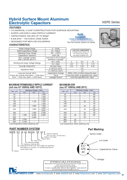
51®NIC COMPONENTS CORP. www www www ww Hybrid Surface Mount Aluminum Electrolytic CapacitorsNSPE SeriesPart MarkingCapacitance ValueVoltageLot CodeSeries Code4704VE17CHARACTERISTICSFEATURES• CYLINDRICAL V-CHIP CONSTRUCTION FOR SURFACE MOUNTING • SUPER LOW ESR & HIGH RIPPLE CURRENT• CAPACITANCE VALUES UP TO 820µF• 6.3x6.3mm ~ 10x10.8mm CASE SIZES• DESIGNED FOR REFLOW SOLDERING LOW ESR COMPONENT HYBRID ELECTROLYTEFor Performance Data see NSPE 471 M 4V 8x10.8 TR 13 FRoHS Compliant97% Sn (min.), 3% Bi (max.) 330mm (13”) Reel Tape & Reel Size in mm Working Voltage Tolerance Code M=20% Capacitance Code in µF, fi rst 2 digits are signifi cant Third digit is no. of zeros, “R” indicates decimal for values under 10µF SeriesPART NUMBER SYSTEMCap. (µF)Working Votage (Vdc)4.0 6.31022--1,02033--1,02047--1,020100-1,1201,550150--1,550220-1,5501,550330-1,5501,550*2090390-1,5502,0904701,5502,0902,090*560-2,090-6802,090--8202,180--Cap. (µF)Working Votage (Vdc)4.0 6.31022--6033--6047--60100-5030150--30220-3030330-3030*25390-3025470302525*560-25-68025--82023--MAXIMUM PERMISSIBLE RIPPLE CURRENT(mA rms AT 100KHz AND 105O C)MAXIMUM ESR(m Ω AT 100KHz AND 20O C)PRECAUTIONSPlease review the notes on correct use, safety and precautions found on pages T10 & T11of NIC’s Electrolytic Capacitor catalog . Also found at /precautionsIf in doubt or uncertainty, please review your speci fi c application - process details withNIC’s technical support personnel: tpmg@Rated Voltage Range4 ~ 10VdcRated Capacitance Range 22 ~ 820µFOperating Temp. Range -55 ~ +105°C Capacitance Tolerance ±20% (M)Max. Leakage Current After 2 Minutes @ 20°C Less than 0.1CV or 50µA whichever is greaterWorking and Surge Voltage RatingsW.V. (Vdc)4 6.310S.V. (Vdc) 4.67.211.5Tan δ @ 120Hz/20°C All Case Sizes 0.240.220.20Impedance RatioZ -55°C/Z +20°C 2.5Z +105°C/Z +20°C 1.0Load Life Test @ 105°C6.3mm Dia. and All 4Vdc parts = 1,000 Hours 8mm ~ 10mm Dia. parts = 2,000 HoursCapacitance Change Within ±20% of initial measured valueTan δLess than 200% of specifi ed max. value Leakage Current Less than specifi ed max. value*Low temperature refl ow soldering only *Low temperature refl ow soldering only RoHSCompliantincludes all homogeneous materials *See Part Number System for DetailsNSPE SeriesHybrid Aluminum Electrolytic CapacitorsRECOMMENDED REFLOW SOLDERING PROFILE50100150200Time (Seconds)Temperature-Deg.C230B STANDARD PRODUCT AND CASE SIZE TABLE Dφ x L (mm)V-chip SMT Aluminum Electrolytic Capacitors/RSL52。
NACV100M250V10x10.8TR13F中文资料

16®NIC COMPONENTS CORP. www www www www .SMTmagnetics.comSurface Mount Aluminum Electrolytic CapacitorsNACV SeriesFEATURES•CYLINDRICAL V-CHIP CONSTRUCTION FOR SURFACE MOUNT •HIGH VOLT AGE (160VDC AND 400VDC)•8 x10.8mm ~ 16 x17mm CASE SIZES •LONG LIFE (2000 HOURS A T +105O C)•DESIGNED FOR REFLOW SOLDERING CHARACTERISTICSDIMENSIONS (mm)CE MOUNT RoHSCompliantincludes all homogeneous materials *See Part Number System for DetailsNACV 100 M 200V 10x10.8 TR 13 FRoHS Compliant97% Sn (min.), 3% Bi (max.) 330mm (13”) Reel Tape & Reel Size in mm Working VoltageT olerance Code M=20%, K=10% Capacitance Code in µF , fi rst 2 digits are signifi cant Third digit is no. of zeros, “R” indicates decimal for values under 10mF SeriesPART NUMBER SYSTEM0.3mm max.D φL+ -IIWPABSTANDARD PRODUCTS AND CASE SIZES (mm)MAXIMUM RIPPLE CURRENT(mA rms AT 120Hz AND 105°C)MAXIMUM ESR (Ω AT 120Hz AND 20°C)Rated Voltage Range 160200250400Rated Capacitance Range 10 ~ 8210 ~ 68 3.3 ~ 47 2.2 ~ 22Operating Temperature Range-40 ~ +105°C Capacitance Tolerance ±20% (M)Max. Leakage Current After 2 Minutes0.03CV + 15µA 0.02CV + 25µAMax. Tan δ @ 120Hz0.200.200.200.25Low Temperature Stability(Impedance Ratio @ 120Hz)Z-25°C/Z+20°C 3336Z-40°C/Z+20°C66610High Temperature Load Life at 105°C2,000 hrs φD > 10mm 1,000 hrs φD = 8mm Capacitance Change Within ±25% of initial measured value Tan δLess than 200% of specifi ed value Leakage CurrentLess than the specifi ed valueCap. (µF)Working Voltage 1602002504002.2---253.3--31364.7--37386.8--444710576464572211211211211533137137150-47180180180-68215215--82235---Cap. (µF)Working Voltage 1602002504002.2---188.53.3--100.5125.74.7--70.688.26.8--48.861.01033.233.233.241.52215.115.115.118.83310.110.110.1-477.17.17.1-68 4.9 4.9--824.0---Cap. (µF)Code Working Voltage1602002504002.22R2---8x10.83.33R3--8x10.810x10.84.74R7--8x10.810x10.86.86R8--8x10.812.5x14101008x10.810x10.810x10.812.5x142222012.5x1412.5x1412.5x1416x173333012.5x1412.5x1416x17-4747016x1716x1716x17-6868016x1716x17--8282016x17---Case Size D φ±0.5L max.A±0.2B±0.2I±0.2W P±0.28x10.88.010.88.38.3 2.90.7~1.0 3.210x10.810.010.810.310.3 3.2 1.1~1.4 4.612.5x1412.514.012.812.8 4.5 1.1~1.4 4.616x1716.017.016.316.35.01.8~2.17.0PRECAUTIONSPlease review the notes on correct use, safety and precautions found on pages T10 & T11of NIC’s Electrolytic Capacitor catalog . Also found at /precautionsIf in doubt or uncertainty, please review your specifi c application - process details withNIC’s technical support personnel: tpmg@元器件交易网。
NACE中文资料
1®NIC COMPONENTS CORP. ww www www www Surface Mount Aluminum Electrolytic CapacitorsNACE SeriesFEATURES•CYLINDRICAL V-CHIP CONSTRUCTION• LOW COST, GENERAL PURPOSE, 2000 HOURS AT 85O C •NEW EXP ANDED CV RANGE (up to 6800µF)•ANTI-SOLVENT (2 MINUTES)•DESIGNED FOR AUTOMATIC MOUNTING AND REFLOW SOLDERINGCHARACTERISTICS*See standard products and case size table for items available in 10% toleranceRated Voltage Range 4.0 ~ 100Vdc Rate Capacitance Range 0.1 ~ 6,800µFOerating Temp. Range -40°C ~ +85°CCapacitance Tolerance ±20% (M), ±10%Max. Leakage Current After 2 Minutes @ 20°C0.01CV or 3µA whichever is greaterTan δ @120Hz/20°C W.V . (Vdc) 4.0 6.31016253550631003mm Dia.0.400.350.240.190.160.140.14--4 ~ 6.3mm Dia.0.350.260.200.160.140.120.100.100.108x6.5mm Dia.-0.250.260.200.160.140.12-0.108mm Dia. ~ upC<1000µF 0.400.300.240.200.160.140.120.120.10C<1500µF -0.310.250.21-0.15---C<2200µF -0.320.32-0.18----C<3300µF -0.34-0.24-----C<4700µF --0.36------C<6800µF -0.40-------Low Temperature StabilityImpedance Ratio @ 120HzW.V . (Vdc) 4.0 6.3101625355063100Z-25°C/Z+20°C 733222222Z-40°C/Z+20°C 1586443333Load Life Test85°C 2,000 HoursCapacitance Change Within ± 25% of initial measured valueTan δLess than 200% of specifi ed max. valueLeakage Current Less than specifi ed max. value NACE 101 M 16V 6.3x5.5 TR 13 FRoHS Compliant97% Sn (min.), 3% Bi (max.) 330mm (13”) Reel Tape & Reel Size in mm Working VoltageTolerance Code M=20%, K=10% Capacitance Code in µF , fi rst 2 digits are signifi cant Third digit is no. of zeros, “R” indicates decimal for values under 10µF SeriesPART NUMBER SYSTEMRoHSCompliantincludes all homogeneous materials *See Part Number System for Details PRECAUTIONSPlease review the notes on correct use, safety and precautions found on pages T10 & T11of NIC’s Electrolytic Capacitor catalog . Also found at /precautionsIf in doubt or uncertainty, please review your specifi c application - process details withNIC’s technical support personnel: tpmg@2MAXIMUM RIPPLE CURRENT O MAXIMUM ESRO Surface Mount Aluminum Electrolytic CapacitorsNACE SeriesSTANDARD PRODUCT AND CASE SIZE TABLE DφxL (mm)*Items available in optional 10% toleranceSurface Mount Aluminum Electrolytic Capacitors NACE Series+ -3。
NACV6R8K250V12.5x14TR13F中文资料

16®NIC COMPONENTS CORP. www www www www .SMTmagnetics.comSurface Mount Aluminum Electrolytic CapacitorsNACV SeriesFEATURES•CYLINDRICAL V-CHIP CONSTRUCTION FOR SURFACE MOUNT •HIGH VOLT AGE (160VDC AND 400VDC)•8 x10.8mm ~ 16 x17mm CASE SIZES •LONG LIFE (2000 HOURS A T +105O C)•DESIGNED FOR REFLOW SOLDERING CHARACTERISTICSDIMENSIONS (mm)CE MOUNT RoHSCompliantincludes all homogeneous materials *See Part Number System for DetailsNACV 100 M 200V 10x10.8 TR 13 FRoHS Compliant97% Sn (min.), 3% Bi (max.) 330mm (13”) Reel Tape & Reel Size in mm Working VoltageT olerance Code M=20%, K=10% Capacitance Code in µF , fi rst 2 digits are signifi cant Third digit is no. of zeros, “R” indicates decimal for values under 10mF SeriesPART NUMBER SYSTEM0.3mm max.D φL+ -IIWPABSTANDARD PRODUCTS AND CASE SIZES (mm)MAXIMUM RIPPLE CURRENT(mA rms AT 120Hz AND 105°C)MAXIMUM ESR (Ω AT 120Hz AND 20°C)Rated Voltage Range 160200250400Rated Capacitance Range 10 ~ 8210 ~ 68 3.3 ~ 47 2.2 ~ 22Operating Temperature Range-40 ~ +105°C Capacitance Tolerance ±20% (M)Max. Leakage Current After 2 Minutes0.03CV + 15µA 0.02CV + 25µAMax. Tan δ @ 120Hz0.200.200.200.25Low Temperature Stability(Impedance Ratio @ 120Hz)Z-25°C/Z+20°C 3336Z-40°C/Z+20°C66610High Temperature Load Life at 105°C2,000 hrs φD > 10mm 1,000 hrs φD = 8mm Capacitance Change Within ±25% of initial measured value Tan δLess than 200% of specifi ed value Leakage CurrentLess than the specifi ed valueCap. (µF)Working Voltage 1602002504002.2---253.3--31364.7--37386.8--444710576464572211211211211533137137150-47180180180-68215215--82235---Cap. (µF)Working Voltage 1602002504002.2---188.53.3--100.5125.74.7--70.688.26.8--48.861.01033.233.233.241.52215.115.115.118.83310.110.110.1-477.17.17.1-68 4.9 4.9--824.0---Cap. (µF)Code Working Voltage1602002504002.22R2---8x10.83.33R3--8x10.810x10.84.74R7--8x10.810x10.86.86R8--8x10.812.5x14101008x10.810x10.810x10.812.5x142222012.5x1412.5x1412.5x1416x173333012.5x1412.5x1416x17-4747016x1716x1716x17-6868016x1716x17--8282016x17---Case Size D φ±0.5L max.A±0.2B±0.2I±0.2W P±0.28x10.88.010.88.38.3 2.90.7~1.0 3.210x10.810.010.810.310.3 3.2 1.1~1.4 4.612.5x1412.514.012.812.8 4.5 1.1~1.4 4.616x1716.017.016.316.35.01.8~2.17.0PRECAUTIONSPlease review the notes on correct use, safety and precautions found on pages T10 & T11of NIC’s Electrolytic Capacitor catalog . Also found at /precautionsIf in doubt or uncertainty, please review your specifi c application - process details withNIC’s technical support personnel: tpmg@元器件交易网。
NACEW4R7K356.3x6.3TR13F中文资料

NACEW Series
8x10.5 8x10.5 10x10.5* 12.5x14 10x8 1000 102 8x10.5* 10x10.5* 12.5x14 1500 152 10x10.5* 12.5x14 16x17 2200 222 12.5x14 16x17 3300 332 12.5x14 16x17 4700 472 16x17 6800 682 16x17 *Denotes values available in 10% tolerance
DIMENSIONS (mm)
Case Size Dφ ±0.5 L max. A ±0.2 B ±0.2 I ±0.2 4 x 5.5 4.0 5.5 4.3 4.3 1.8 5 x 5.5 5.0 5.5 5.3 5.3 2.1 6.3 x 5.5 6.3 5.5 6.6 6.6 2.5 6.3 x 6.3 6.3 6.3 6.6 6.6 2.5 6.3 x 8 6.3 8.0 6.6 6.6 2.5 8 x 6.5 8.0 6.5 8.3 8.3 3.4 8 X 10.5 8.0 10.5 8.3 8.3 2.9 10 x 8 10.0 8.0 10.3 10.3 3.2 10 x 10.5 10.0 10.5 10.3 10.3 3.2 12.5 x 14 12.5 14.0 12.8 12.8 4.5 16 x 17 16.0 17.5 17.0 17.0 5.5 W 0.5 ~ 0.8 0.5 ~ 0.8 0.5 ~ 0.8 0.5 ~ 0.8 0.5 ~ 0.8 0.5 ~ 0.8 0.7 ~ 1.0 0.7 ~ 1.4 0.7 ~ 1.4 0.6 ~ 1.4 0.9 ~ 1.5 P ±0.2 1.0 1.4 2.2 2.2 2.2 2.2 3.2 4.6 4.6 4.6 6.7
VN02NSP13TR资料

1/12June 2004VN02NSP VN02NPTHIGH SIDE SMART POWER SOLID STATE RELAYREV. 2Table 1. General Features■OUTPUT CURRENT (CONTINUOUS): 6A @ T c =25°C■5V LOGIC LEVEL COMPATIBLE INPUT ■THERMAL SHUT-DOWN ■UNDER VOLTAGE SHUT-DOWN ■OPEN DRAIN DIAGNOSTIC OUTPUT ■VERY LOW STAND-BY POWER DISSIPATIONDESCRIPTIONThe VN02NSP/VN02NPT are monolithic devices made using STMicroelectronics VIPower Technology, intended for driving resistive or inductive loads with one side grounded.Built-in thermal shut-down protects the chip from over temperature and short circuit.The input control is 5V logic level compatible.The open drain diagnostic output indicates open circuit (no load) and over temperature status.Table 2. Order CodesType V DSS R DS(on)I OUT V CC VN02NSP VN02NPT60 V0.4 Ω6 A26 VPackageTubeTape and Reel PowerSO-10 VN02NSPVN02NSP13TR PP AKVN02NPTVN02NPT13TRVN02NSP/VN02NPT2/12Table 3. Absolute Maximum RatingsSymbol ParameterValueUnit PowerSO-10PPAKV (BR)DSS Drain-Source Breakdown Voltage 60V I OUT Output Current (cont.)6A I R Reverse Output Current –6A I IN Input Current±10mA – V CC Reverse Supply Voltage –4V I STA T Status Current±10mA V ESD Electrostatic Discharge (1.5 k Ω, 100 pF)2000V P tot Power Dissipation at T c ≤ 25 °C 5846W T j Junction Operating Temperature -40 to 150°C T stgStorage Temperature-55 to 150°C3/12VN02NSP/VN02NPTTable 4. Thermal DataNote: 1.When mounted using minimum recommended pad size on FR-4 board.Symbol ParameterValueUnit PowerSO-10PPAK R thj-case Thermal Resistance Junction-case Max 2.14 3.33°C/W R thj-ambThermal Resistance Junction-ambient (1)Max62.5100°C/WVN02NSP/VN02NPT4/12ELECTRICAL CHARACTERISTICS(V CC = 13 V; –40 ≤ Tj ≤ 125 °C unless otherwise specified)Table 5. PowerTable 6. SwitchingTable 7. Logic InputNote: 2.The V IH is internally clamped at 6V about. It is possible to connect this pin to an higher voltage via an external resistor calculatedto not exceed 10 mA at the input pin.Symbol ParameterTest ConditionsMin.Typ.Max.Unit V CC Supply Voltage 726V R on On State Resistance I OUT = 3 AI OUT = 3 A; T j = 25 °C 0.80.4ΩΩI SSupply CurrentOff State; T j ≥ 25 °C On State5015µA mASymbol ParameterTest ConditionsMin.Typ. Max.Unit t d(on)T urn-on Delay Time Of Output Current I OUT = 3 A; Resistive LoadInput Rise Time < 0.1 µs; T j = 25 °C 10µs t r Rise Time Of Output CurrentI OUT = 3 A; Resistive LoadInput Rise Time < 0.1 µs; T j = 25 °C 15µs t d(off)T urn-off Delay Time Of Output Current I OUT = 3 A; Resistive LoadInput Rise Time < 0.1 µs; T j = 25 °C 15µs t f Fall Time Of Output CurrentI OUT = 3 A; Resistive LoadInput Rise Time < 0.1 µs; T j = 25 °C 6µs (di/dt)on T urn-on Current Slope I OUT = 3 A I OUT = I OV 0.52A/µs A/µs (di/dt)offT urn-off Current SlopeI OUT = 3 A I OUT = I OV24A/µs A/µsSymbol ParameterTest ConditionsMin.Typ.Max.Unit V IL Input Low Level Voltage 0.8V V IH Input High Level Voltage 2Note 2V V I(hyst)Input Hysteresis Voltage 0.5V I IN Input Current V IN = 5 V 250500µA V ICLInput Clamp VoltageI IN = 10 mA I IN = –10 mA6–0.7V VVN02NSP/VN02NPT ELECTRICAL CHARACTERISTICS (cont’d)Table 8. Protections and DiagnosticsNote: 3.Status determination > 100 ms after the switching edge.FUNCTIONAL DESCRIPTIONThe device has a diagnostic output which indicates open circuit (no load) and over temperature conditions. The output signals are processed by internal logic.To protect the device against short circuit and over-current condition, the thermal protection turns the integrated Power MOS off at a minimum junction temperature of 140 °C. When the temperature returns to about 125 °C the switch is automatically turned on again.In short circuit conditions the protection reacts with virtually no delay, the sensor being located in the region of the die where the heat is generated. PROTECTING THE DEVICE AGAINST REVERSE BATTERYThe simplest way to protect the device against a continuous reverse battery voltage (-26V) is to insert a Schottky diode between pin 1 (GND) and ground, as shown in the typical application circuit (Figure 7).The consequences of the voltage drop across this diode are as follows:–If the input is pulled to power GND, a negative voltage of -V F is seen by the device. (V IL, V IH thresholds and V STAT are increased by V F withrespect to power GND).–The undervoltage shutdown level is increased by V F.If there is no need for the control unit to handle external analog signals referred to the power G ND, the best approach is to connect the reference potential of the control unit to node (1) (see application circuit in Figure 8), which becomes the common signal GND for the whole control board.In this way no shift of V IH, V IL and V STAT takes place and no negative voltage appears on the INPUT pin; this solution allows the use of a standard diode, with a breakdown voltage able to handle any ISO normalized negative pulses that occurs in the automotive environment.Symbol Parameter Test Conditions Min.Typ. Max.Unit V STAT(3)Status Voltage OutputLowI STAT = 1.6 mA0.4V V USD Under Voltage Shut Down 6.5VV SCL(3)Status Clamp Voltage I STAT = 10 mAI STAT = –10 mA6–0.7VVt sc Switch-off Time in ShortCircuit Condition at Start-UpR LOAD < 10 mΩ;Tc = 25 °C 1.55msI OV Over Current R LOAD < 10 mΩ –40 ≤ T c≤ 125 °C28AI AV Average Current in ShortCircuitR LOAD < 10 mΩ; Tc = 85 °C0.9AI OL Open Load Current Level570mAT TSD Thermal Shut-downT emperature140°CT R Reset T emperature125°C5/12VN02NSP/VN02NPT6/12Table 9. Truth TableInputOutput DiagnosticNormal Operation L H L H H H Open Circuit (No Load)H H L Over-temperature H L L Under-voltageXLHVN02NSP/VN02NPT7/12VN02NSP/VN02NPT8/12Figure 9. R DS(on) vs Junction TemperatureFigure 10. R DS(on) vs Supply VoltageFigure 11. R DS(on) vs Output CurrentFigure 12. Input voltages vs Junction TemperatureFigure 13. Output Current DeratingFigure 14. Open Load vs Junction Temperature9/12VN02NSP/VN02NPTPACKAGE MECHANICALTable 10. PowerSO-10 Mechanical DataNote:Drawing is not to scale.Symbol millimetersMin TypMax A 3.35 3.65A (*) 3.4 3.6A10.000.10B 0.400.60B (*)0.370.53C 0.350.55C (*)0.230.32D 9.409.60D17.407.60E 9.309.50E27.207.60E2 (*)7.307.50E4 5.90 6.10E4 (*) 5.90 6.30e 1.27F 1.25 1.35F (*) 1.20 1.40H 13.8014.40H (*)13.8514.35h 0.50L 1.20 1.80L (*)0.80 1.10a 0º8ºα (*)2º8ºVN02NSP/VN02NPT10/12Table 11. PPAK Mechanical DataSymbol millimetersMin TypMax A 2.20 2.40A10.90 1.10A20.030.23B 0.400.60B2 5.20 5.40C 0.450.60C20.480.60D1 5.1D 6.00 6.20E 6.406.60E1 4.7e 1.27G 4.90 5.25G1 2.38 2.70H 9.3510.10L20.81.00L40.601.00R 0.2V20º8ºPackage WeightGr. 0.3VN02NSP/VN02NPT REVISION HISTORYTable 12. Revision HistoryDate Revision Description of Changes September-19971First Issue18-June-20042Stylesheet update. No content change.11/12VN02NSP/VN02NPTInformation furnished is believed to be accurate and reliable. However, STMicroelectronics assumes no responsibility for the consequences of use of such information nor for any infringement of patents or other rights of third parties which may result from its use. No license is granted by implication or otherwise under any patent or patent rights of STMicroelectronics. Specifications mentioned in this publication are subject to change without notice. This publication supersedes and replaces all information previously supplied. STMicroelectronics products are not authorized for use as critical components in life support devices or systems without express written approval of STMicroelectronics.The ST logo is a registered trademark of STMicroelectronics.All other names are the property of their respective owners© 2004 STMicroelectronics - All rights reservedSTMicroelectronics GROUP OF COMPANIESAustralia - Belgium - Brazil - Canada - China - Czech Republic - Finland - France - Germany - Hong Kong - India - Israel - Italy - Japan - Malaysia - Malta - Morocco - Singapore - Spain - Sweden - Switzerland - United Kingdom - United States12/12。
- 1、下载文档前请自行甄别文档内容的完整性,平台不提供额外的编辑、内容补充、找答案等附加服务。
- 2、"仅部分预览"的文档,不可在线预览部分如存在完整性等问题,可反馈申请退款(可完整预览的文档不适用该条件!)。
- 3、如文档侵犯您的权益,请联系客服反馈,我们会尽快为您处理(人工客服工作时间:9:00-18:30)。
1
®
NIC COMPONENTS CORP. ww www www www
Surface Mount Aluminum Electrolytic Capacitors
NACE Series
FEATURES
•CYLINDRICAL V-CHIP CONSTRUCTION
• LOW COST, GENERAL PURPOSE, 2000 HOURS AT 85O C •NEW EXP ANDED CV RANGE (up to 6800µF)•ANTI-SOLVENT (2 MINUTES)
•DESIGNED FOR AUTOMATIC MOUNTING AND REFLOW SOLDERING
CHARACTERISTICS
*See standard products and case size table for items available in 10% tolerance
Rated Voltage Range 4.0 ~ 100Vdc Rate Capacitance Range 0.1 ~ 6,800µF
Oerating Temp. Range -40°C ~ +85°C
Capacitance Tolerance ±20% (M), ±10%Max. Leakage Current After 2 Minutes @ 20°C
0.01CV or 3µA whichever is greater
Tan δ @120Hz/20°C W.V . (Vdc) 4.0 6.31016253550631003mm Dia.0.400.350.240.190.160.140.14--4 ~ 6.3mm Dia.0.350.260.200.160.140.120.100.100.108x6.5mm Dia.-0.250.260.200.160.140.12
-0.108mm Dia. ~ up
C<1000µF 0.400.300.240.200.160.140.12
0.120.10C<1500µF -0.310.250.21-0.15---C<2200µF -0.320.32-0.18----C<3300µF -0.34-0.24-----C<4700µF --0.36------C<6800µF -0.40-------Low Temperature Stability
Impedance Ratio @ 120Hz
W.V . (Vdc) 4.0 6.31016253550
63100Z-25°C/Z+20°C 7332222
22Z-40°C/Z+20°C 1586443333
Load Life Test
85°C 2,000 Hours
Capacitance Change Within ± 25% of initial measured value
Tan δLess than 200% of specifi ed max. value
Leakage Current Less than specifi ed max. value NACE 101 M 16V 6.3x5.5 TR 13 F
RoHS Compliant
97% Sn (min.), 3% Bi (max.) 330mm (13”) Reel Tape & Reel Size in mm Working Voltage
Tolerance Code M=20%, K=10% Capacitance Code in µF , fi rst 2 digits are signifi cant Third digit is no. of zeros, “R” indicates decimal for values under 10µF Series
PART NUMBER SYSTEM
RoHS
Compliant
includes all homogeneous materials *See Part Number System for Details PRECAUTIONS
Please review the notes on correct use, safety and precautions found on pages T10 & T11
of NIC’s Electrolytic Capacitor catalog . Also found at /precautions
If in doubt or uncertainty, please review your specifi c application - process details with
NIC’s technical support personnel: tpmg@
2
MAXIMUM RIPPLE CURRENT O MAXIMUM ESR
O Surface Mount Aluminum Electrolytic Capacitors
NACE Series
STANDARD PRODUCT AND CASE SIZE TABLE DφxL (mm)
*Items available in optional 10% tolerance
Surface Mount Aluminum Electrolytic Capacitors NACE Series
+ -
3。
