RB161VA-20中文资料
N6 无缝切换器 用户手册说明书

N6无缝切换器V3.0.0用户手册版权所有©2020西安诺瓦星云科技股份有限公司。
保留一切权利。
非经本公司书面许可,任何单位和个人不得擅自摘抄、复制本文档内容的部分或全部,并不得以任何形式传播。
商标声明是诺瓦科技的注册商标。
声明欢迎您选用西安诺瓦星云科技股份有限公司(以下简称诺瓦科技)的产品,如果本文档为您了解和使用产品带来帮助和便利,我们深感欣慰。
我们在编写文档时力求精确可靠,随时可能对内容进行修改或变更,恕不另行通知。
如果您在使用中遇到任何问题,或者有好的建议,请按照文档提供的联系方式联系我们。
对您在使用中遇到的问题,我们会尽力给予支持,对您提出的建议,我们衷心感谢并会尽快评估采纳。
目录1 产品概述 (1)产品简介 (1)产品特性 (1)2 外观说明 (3)前面板 (3)后面板 (4)产品尺寸 (5)3 应用场景 (6)4 液晶屏菜单操作 (7)操作说明 (7)主界面 (7)屏体配置 (9)4.3.2 输出模式 (9)4.3.3 屏体结构 (10)4.3.4 输出设置 (10)4.3.5 输出接口配置 (11)窗口设置 (11)4.4.1 窗口分屏模板 (11)4.4.2 BKG配置 (12)4.4.3 窗口配置 (13)场景设置 (14)输入设置 (15)画面控制 (15)测试画面 (16)预监选择 (17)高级设置 (18)4.10.2 系统模式 (18)4.10.3 同步模式 (18)4.10.4 AUX (18)4.10.5 Fn键设置 (19)4.10.6 返回主界面时长 (20)4.10.7 工厂复位 (20)4.10.8 HDCP开关 (20)4.10.9 硬件版本 (20)4.10.10 设备自检 (21)4.10.11 关于我们 (21)通讯设置 (21)5 V-CAN控制 (23)6 C1控制 (25)7 常见问题 (27)8 规格参数 (28)1 产品概述产品简介N6是由诺瓦科技自主研发的集视频处理,画面拼接,特效切换和多画面显示的高性能无缝切换器。
施耐德E型接触器
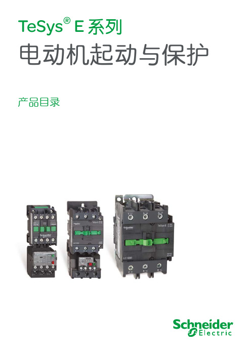
电动机起动与保护
产品目录
施耐德电气
善用其效 尽享其能
全球能效管理专家施耐德电气为世界100多个国家提供整体解决方案,其中在能源与基 础设施、工业过程控制、楼宇自动化和数据中心与网络等市场处于世界领先地位,在 住宅应用领域也拥有强大的市场能力。致力于为客户提供安全、可靠、高效的能源, 施耐德电气2010年的销售额为196亿欧元,拥有超过110,000名员工。施耐德电气助 您——善用其效,尽享其能!
17...80 A p
LC1E65
80A 110A
3 22 kW 37 kW 45 kW 55 kW 45 kW 45 kW
17...104 A p
LC1E80
95A 110A
3 25 kW 45 kW 45 kW 55 kW 45 kW 45 kW
17...104 A p
LC1E95
3
特性
TeSys® E 接触器
1
选型指南
应用
TeSys® E 接触器
LC1E06到E95
各种类型的控制系统
额定工作电流
额定工作电压 极数 额定工作功率 AC-3 类
辅助触点 适用手动-过载继电 浪涌抑制模块 接触器型号 页码
Ie max AC-3 (Ue≤440 V) Ie AC-1 (q≤60˚C)
220/230 V 380 V 415/440 V 500 V 660/690 V 1000 V
LC1E06到E95
接触器型号
工作环境
额定绝缘电压 (Ui) 额定冲击耐受电压 (Uimp) 符合标准 产品证书 绝缘隔离 防护等级 (1) (仅适用于正面) 保护措施 环境温度 设备周围
最大工作海拔 工作位置
BF6910(BF6911)ASXX规格书
3.1 引脚图 ....................................................................................................................................................... 6 3.2 引脚描述 ................................................................................................................................................... 6
RBT_MBVA_V20A单板调试步骤
RBT_MBVA_V20A单板调试步骤一.测试工具1、24V电源2、万用表3、USB转RS232转接线4、网线一根(交叉线)5、SD卡6、摇杆、薄膜按键7、测试用IO板一块,用于测试单板上的CAN接口8、显示屏、触摸屏各一块二.测试软件1.STM32程序烧写使用J-Flash ARM软件,选择STM32F103VC,烧写180公斤码垛机器人v1.0.0程序中的示教器/STM32程序。
2.SD卡制作在linux系统中执行SD卡制作文件夹中的create-sdcard.sh制作示教器系统。
三.测试流程1.单板外观测试重点检查(1)单板是否有锡渣造成短路;(2)插件多余的插脚是否遗留在单板上;(3)器件是否偏位;(4)电解电容记性是否反了。
(5)芯片1管脚焊接是否正确2.单板阻抗测试关键电源是否有短路,一般情况电源阻抗会在100欧姆以上,若阻抗偏低应当引起重视。
(1)电源入口处(入口连接器J10的PIN5和PIN7之间的阻抗);FB1 FB2(2)电感L8的PIN1和PIN2之间的阻抗,PIN3和PIN4之间的阻抗;(3)电容CP12、CP13之间的阻抗;(4)所有的钽电容CP18~CP20、CP1~CP3、CP6~CP7的阻抗;(5)TP20(VCC2V5)对地之间的阻抗;(6)电阻R638对地之间的阻抗;3.单板上电测试(1)确定24V电压正常,CP12、CP13之间电压;(2)确定3.3V电压正常,CP18~CP20之间的电压;(3)确定VCC5VA电压正常,CP1~CP3之间的电压;(4)确定VCC5VB电压正常,CP6~CP7的电压;(5)确定VCC2V5电压正常,TP20对地之间的电压;(6)电阻R638对地之间的电压,2.0V左右;4.STM32烧结测试将STM32F103的程序烧结到单片机中,看程序是否能成功烧结。
5.调试串口测试(1)连接好调试串口线和电源线,启动电源,串口应以500毫秒的周期输出C 字符;调试串口插座为J16(2)插上SD卡,连接好调试串口线、电源线,启动电源,打印窗口能够看到BOOT启动信息,直到打印到登陆界面为止;(3)帐户:root 密码:throbot1236.网口测试(1)更改电脑上的IP为192.168.1.x ,插上网线,另一端连接J8,(RJ45插座),在电脑上ping 192.168.1.20如果接收数据正常,则网口通讯正常;(2)更改电脑上的IP为192.168.10.x ,插上网线,另一端连接J6,(RJ45插座),在电脑上ping 192.168.10.20如果接收数据正常,则网口通讯正常;7.显示屏、触摸屏测试(1)接上显示屏,上电之后能够看到开机画面(2)接上触摸屏,看触摸屏是否正常,如果串口输入ts_calibrate命令后可以进行触摸屏校准;8.遥感测试(1)进入系统后,使用命令cat /dev/ttyO1|hexdump命令监听串口/dev/ttyO1,此时摇动摇杆,应能收到摇杆数据,测试完毕后,Ctrl+C终止cat命令。
ZVN4206AV中文资料

On-resistance v drain current
Normalised RDS(on) and VGS(th) v Temperature
ZVN4206AV
TYPICAL CHARACTERISTICS
1000 1000
gfs-Transconductance (mS)
700 600 500 400 300 200 100 0 0 1 2
10
VGS=3.5V
4.5V
6V
8V 10V 2.6
Normalised RDS(on) and VGS(th)
2.4 2.2 2.0 1.8 1.6 1.4 1.2 1.0 0.8 0.6 -50 -25
n) (o
VGS=10V ID=1.5A
14V 1.0 20V 20V
Dr
e eR rc ou -S ain
ZVN4206AV
TYPICAL CHARACTERISTICS
10 VGS= 20V 16V 14V 12V 10V 9V 8V 7V 2 6V 5V 4.5V 4V 3.5V 50 10 VGS= 20V 16V 14V 12V 10V 9V 8V 7V 6V 5V 4.5V 4V 3.5V 10
eR nc ta sis
DS
VGS=VDS ID=1mA
Gate Threshold Voltage VGS(TH)
0.1 0.1 1.0 10
0
25 50 75 100 125 150 175 200 225
ID-Drain Current (Amps)
Tj-Junction Temperature (°C)
ABSOLUTE MAXIMUM RATINGS.
TDA2030A中文资料
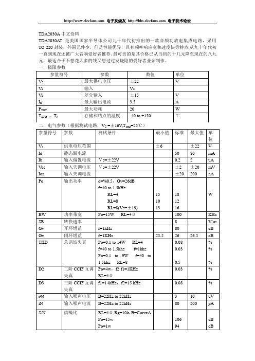
TDA2030AT是美国国家半导体公司九十年代初推出的一款音频功放电集成电路,采用TO-220封装,外围元件少,但是性能优异,具有频率响应宽和速度快等特点,从九十年代初一直到现在还被广大音响爱好者推荐。最可贵的是其价格已从当初的十几元降至现在的八九元,最适合于不想花太多的钱又想过过发烧隐的爱好者业余制作。
W
BW
功率带宽
Po=15W RL=4Ω
100
KHz
SR
转换速率
8
V/us
Gv
开环增益
f=1kHz
80
dB
Gv
闭环增益
f=1KHz
25.5
26
26.5
dB
THD
总谐波失真
Po=0.1 to 14W RL=4
f=40 to 1.5khz f=1khz
Po=0.1 to 9W f=40 to 1.5khz RL=8
一极限参数二电气参数根据测试电路v16vtamp25参量符号参数测试条件最小值标准最大值id静态漏电流5080maib输入偏置电流vs22vuavos输入失调电压vs22v20mvios输入失调电流20200napo输出功率d05gv26dbf4015khzrl4rl8rl8vs19151013181216bw功率带宽po15wrl4100khzsr转换速率vusgv开环增益f1khz80dbgv闭环增益f1khz25526265dbthd总谐波失真po0114wrl4f4015khzf1khzpo019wf4015khzrl800800305d2二阶ccif互调失真po4wf2f11khzrl4d3三阶ccif互调失真f114khzf215khz008en输入噪声电压b22hz10uv输入噪声电流b22hz22khz80200pa信噪比rl4rg10kbcurveapo15wpo1w10694dbdb参量符号参数数值单位最大供电电压22vi输入vi差分输入15最大输出电流35tot最大功耗20存储和结点的温度40http
SV20中文资料
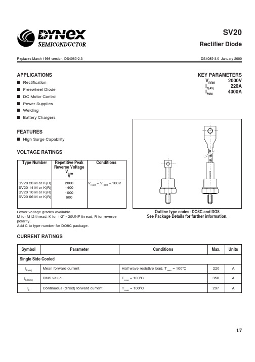
APPLICATIONSs Rectification s Freewheel Diode s DC Motor Control s Power Supplies s Welding s Battery ChargersFEATURESs High Surge CapabilityVOLTAGE RATINGSKEY PARAMETERSV RRM 2000V I F(AV)220A I FSM 4000A200014001000600SV20 20 M or K(R)SV20 14 M or K(R)SV20 10 M or K(R)SV20 06 M or K(R)ConditionsV RSM = V RRM + 100VLower voltage grades available.M for M12 thread. K for 1/2" - 20UNF thread, R for reverse polarity.Add C to type number for DO8C package.Type NumberRepetitive PeakReverse VoltageV RRM VCURRENT RATINGSSymbolParameterConditionsSingle Side Cooled I F(AV)Mean forward current I F(RMS)RMS valueI FContinuous (direct) forward currentUnitsMax.Half wave resistive load, T case = 100o C 220A T case = 100o C350A T case = 100o C297AOutline type codes: DO8C and DO8See Package Details for further information.SV20Rectifier DiodeReplaces March 1998 version, DS4085-2.3DS4085-3.0 January 2000SURGE RATINGSConditions10ms half sine; T case = 175o C V R = 50% V RRM - 1/4 sine 10ms half sine; T case =175o CV R = 0Max.Units Symbol ParameterI FSM Surge (non-repetitive) forward current I 2t I 2t for fusingI FSM Surge (non-repetitive) forward current I 2tI 2t for fusingA 2s4.0kA 51.2 x 10³A 2s 3.2kA 80.0 x 10³THERMAL AND MECHANICAL DATAConditions Min.Max.UnitsoC/W-0.08Thermal resistance - case to heatsinkR th(c-h)Thermal resistance - junction to case R th(j-c)Symbol Parameter-0.23oC/W175oC T vj Virtual junction temperatureT stg Storage temperature range -55200oC--175oCMounting torque 15.0Nm with mounting compound Forward (conducting)Reverse (blocking)dcMounting Torque-12.015.0NmCHARACTERISTICSForward voltage Peak reverse current ParameterµC -Q S Total stored charge Symbol V FM I RRM I RM Peak recovery current 70*-A 200*At V RRM , T case = 175o C-20mA - 1.4V At 600A peak, T case = 25o C ConditionsTyp.Max.Units At T vj = 175˚C-V TO Threshold voltage r TSlope resistance1.0m ΩAt T vj = 175˚C -0.8V t rr reverse recovery time 5.5*-µs I F = 100A, dI RR /dt = 20A/µs, T case = 25˚C*Typical values.CURVESPACKAGE DETAILSFor further package information, please contact your local Customer Service Centre. All dimensions in mm, unless stated otherwise.DO NOT SCALE.ASSOCIATED PUBLICATIONSTitleApplication NoteNumber Calculating the junction temperature or power semiconductors AN4506Thyristor and diode measurement with a multi-meter AN4853Use of V TO, r Ton-state characteristicAN5001CUSTOMER SERVICE CENTRESFrance, Benelux, Italy and Spain T el: +33 (0)1 69 18 90 00. Fax: +33 (0)1 64 46 54 50North America T el: 011-800-5554-5554. Fax: 011-800-5444-5444UK, Germany, Scandinavia & Rest Of World T el: +44 (0)1522 500500. Fax: +44 (0)1522 500020SALES OFFICESFrance, Benelux, Italy and Spain T el: +33 (0)1 69 18 90 00. Fax: +33 (0)1 64 46 54 50Germany T el: 07351 827723North America T el: (613) 723-7035. Fax: (613) 723-1518. T oll Free: 1.888.33.DYNEX (39639) /T el: (831) 440-1988. Fax: (831) 440-1989 / Tel: (949) 733-3005. Fax: (949) 733-2986.UK, Germany, Scandinavia & Rest Of World Tel: +44 (0)1522 500500. Fax: +44 (0)1522 500020These offices are supported by Representatives and Distributors in many countries world-wide.© Dynex Semiconductor 2000 Publication No. DS4085-3 Issue No. 3.0 January 2000TECHNICAL DOCUMENTATION – NOT FOR RESALE. PRINTED IN UNITED KINGDOMHEADQUARTERS OPERATIONS DYNEX SEMICONDUCTOR LTD Doddington Road, Lincoln.Lincolnshire. LN6 3LF. United Kingdom.Tel: 00-44-(0)1522-500500Fax: 00-44-(0)1522-500550DYNEX POWER INC.Unit 7 - 58 Antares Drive,Nepean, Ontario, Canada K2E 7W6.T el: 613.723.7035Fax: 613.723.1518T oll Free: 1.888.33.DYNEX (39639)This publication is issued to provide information only which (unless agreed by the Company in writing) may not be used, applied or reproduced for any purpose nor form part of any order or contract nor to be regarded as a representation relating to the products or services concerned. No warranty or guarantee express or implied is made regarding the capability, performance or suitability of any product or service. The Company reserves the right to alter without prior notice the specification, design or price of any product or service. Information concerning possible methods of use is provided as a guide only and does not constitute any guarantee that such methods of use will be satisfactory in a specific piece of equipment. It is the user's responsibility to fully determine the performance and suitability of any equipment using such information and to ensure that any publication or data used is up to date and has not been superseded. These products are not suitable for use in any medical products whose failure to perform may result in significant injuryor death to the user. All products and materials are sold and services provided subject to the Company's conditions of sale, which are available on request.All brand names and product names used in this publication are trademarks, registered trademarks or trade names of their respective owners.e-mail: power_solutions@Datasheet Annotations:Dynex Semiconductor annotate datasheets in the top right hard corner of the front page, to indicate product status. The annotations are as follows:-Target Information: This is the most tentative form of information and represents a very preliminary specification. No actual design work on the product has been started.Preliminary Information: The product is in design and development. The datasheet represents the product as it is understood but details may change.Advance Information: The product design is complete and final characterisation for volume production is well in hand.No Annotation: The product parameters are fixed and the product is available to datasheet specification.POWER ASSEMBLY CAPABILITYThe Power Assembly group was set up to provide a support service for those customers requiring more than the basic semiconduc-tor, and has developed a flexible range of heatsink / clamping systems in line with advances in device types and the voltage and current capability of our semiconductors.We offer an extensive range of air and liquid cooled assemblies covering the full range of circuit designs in general use today. The Assembly group continues to offer high quality engineering support dedicated to designing new units to satisfy the growing needs of our customers.Using the up to date CAD methods our team of design and applications engineers aim to provide the Power Assembly Complete solution (PACs).HEATSINKSPower Assembly has it’s own proprietary range of extruded aluminium heatsinks. They have been designed to optimise theperformance or our semiconductors. Data with respect to air natural, forced air and liquid cooling (with flow rates) is available on request.For further information on device clamps, heatsinks and assemblies, please contact your nearest Sales Representative or the factory.。
Dell PowerEdge M620 Systems 用户手册说明书

Dell PowerEdge M620 Systems(适用于 Dell PowerEdge VRTX 机柜)用户手册管制型号: HHB管制类型: HHB003注、小心和警告注: “注”表示可以帮助您更好地使用计算机的重要信息。
小心: “小心”表示可能会损坏硬件或导致数据丢失,并说明如何避免此类问题。
警告: “警告”表示可能会造成财产损失、人身伤害甚至死亡。
版权所有© 2014 Dell Inc. 保留所有权利。
本产品受美国、国际版权和知识产权法律保护。
Dell™和 Dell 徽标是 Dell Inc. 在美国和 / 或其他管辖区域的商标。
所有此处提及的其他商标和产品名称可能是其各自所属公司的商标。
2014–10Rev. A01目录1 关于系统 (7)简介 (7)前面板部件和指示灯 (8)使用 USB 软盘或 USB DVD/CD 驱动器 (8)硬盘驱动器功能部件 (8)您可能需要的其他信息 (9)2 使用系统设置程序和引导管理器 (11)选择系统引导模式 (12)进入系统设置 (12)响应错误消息 (12)使用系统设置程序导航键 (12)系统设置选项 (12)系统设置程序主屏幕 (13)系统 BIOS 屏幕 (13)System Information(系统信息)屏幕 (14)Memory Settings(内存设置)屏幕 (14)Processor Settings(处理器设置)屏幕 (15)SATA Settings(SATA 设置)屏幕 (16)Boot Settings(引导设置)屏幕 (16)Integrated Devices(集成设备)屏幕 (17)Serial Communications(串行通信)屏幕 (18)系统配置文件设置屏幕 (18)System Security(系统安全)屏幕 (19)Miscellaneous Settings(其它设置) (20)系统和设置密码功能 (21)分配系统密码和/或设置密码 (21)使用系统密码保护系统安全 (22)删除或更改现有系统密码和/或设置密码 (22)在已启用设置密码的情况下进行操作 (22)进入 UEFI 引导管理器 (23)使用引导管理器导航键 (23)Boot Manager(引导管理器)屏幕 (23)UEFI Boot(UEFI 引导)菜单 (24)嵌入式系统管理 (24)iDRAC 设置公用程序 (24)进入 iDRAC 设置公用程序 (25)3 安装服务器模块组件 (26)建议工具 (26)安装和卸下服务器模块 (26)卸下服务器模块 (26)安装服务器模块 (28)打开与合上服务器模块 (28)打开服务器模块 (28)合上服务器模块 (29)服务器模块内部 (30)冷却导流罩 (30)卸下冷却导流罩 (30)安装冷却导流罩 (31)系统内存 (31)一般内存模块安装原则 (33)模式特定原则 (34)内存配置示例 (35)卸下内存模块 (38)安装内存模块 (39)PCIe 夹层卡 (40)卸下 PCIe 夹层卡 (40)安装 PCIe 夹层卡 (41)管理提升卡 (42)更换 SD 卡 (42)内部 USB 盘 (43)SD vFlash 卡 (43)装回 SD vFlash 卡 (43)网络子卡/LOM 提升卡 (44)卸下网络子卡/LOM 提升卡 (44)安装网络子卡/LOM 提升卡 (45)处理器 (45)卸下处理器 (46)安装处理器 (48)硬盘驱动器 (49)硬盘驱动器/SSD 安装原则 (50)卸下硬盘驱动器/SSD (50)安装硬盘驱动器/SSD (50)进行硬盘驱动器维修前的关机程序 (51)配置引导驱动器 (51)从硬盘驱动器/SSD 托盘中卸下硬盘驱动器/SSD (51)将硬盘驱动器/SSD 安装到硬盘驱动器/SSD 托盘中 (52)硬盘驱动器/SSD 背板 (52)卸下硬盘驱动器/SSD 背板 (52)安装硬盘驱动器/SSD 背板 (53)系统板 (54)卸下系统板 (54)安装系统板 (55)NVRAM 备用电池 (56)更换 NVRAM 备用电池 (56)存储控制器卡 (57)卸下存储控制器卡 (57)安装存储控制器卡 (58)4 系统故障排除 (59)安全第一—为您和您的系统着想 (59)系统内存故障排除 (59)硬盘驱动器故障排除 (59)USB 设备故障排除 (60)内部 SD 卡故障排除 (60)处理器故障排除 (61)系统板故障排除 (61)NVRAM 备用电池故障排除 (61)5 使用系统诊断程序 (63)Dell Online Diagnostics (63)Dell 嵌入式系统诊断程序 (63)何时使用 Embedded System Diagnostics(嵌入式系统诊断程序) (63)运行嵌入式系统诊断程序 (63)从外部介质运行嵌入式系统诊断程序 (64)系统诊断程序控件 (64)6 跳线和连接器 (65)系统板跳线设置 (65)系统板连接器 (66)禁用已忘记的密码 (67)7 技术规格 (68)8 系统消息 (71)LCD 状态信息 (71)查看 LCD 信息 (71)删除 LCD 消息 (71)系统错误消息 (71)警告信息 (141)诊断消息 (142)警报消息 (142)9 获得帮助 (143)联系 Dell (143)1关于系统简介本说明文件提供了有关 Dell PowerEdge M620 服务器模块的信息,该模块专为 PowerEdge VRTX 机柜配置,并且可以通过服务器模块上的标记为PCIe的标签来进行识别。
AZM 161SK_12 12RIA_024_B6L 电磁锁定器说明书
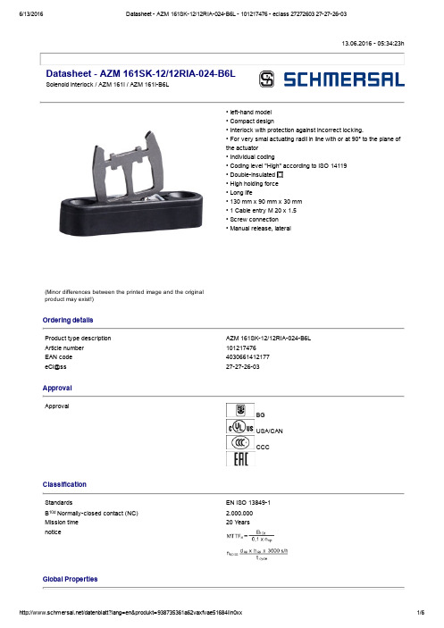
13.06.2016 05:34:23hDatasheet AZM 161SK12/12RIA024B6LSolenoid interlock / AZM 161I / AZM 161IB6L(Minor differences between the printed image and the original product may exist!)• lefthand model • Compact design• Interlock with protection against incorrect locking.• For very smal actuating radii in line with or at 90° to the plane of the actuator• Individual coding• Coding level "High" according to ISO 14119 • Doubleinsulated • High holding force • Long life• 130 mm x 90 mm x 30 mm • 1 Cable entry M 20 x 1.5• Screw connection• Manual release, lateralOrdering detailsProduct type description AZM 161SK12/12RIA024B6L Article number101217476EAN code 4030661412177eCl@ss 27272603ApprovalApprovalBG USA/CAN CCCClassificationStandardsEN ISO 138491B 10d Normallyclosed contact (NC) 2.000.000Mission time 20 Y earsnoticeGlobal PropertiesProduct name AZM 161IStandards EN 6094751, BGGSET19Compliance with the Directives (Y/N) Y esNumber of actuating directions3 pieceActive principle electromechanical Individual coding Coding level "High" according to ISO 14119Duty cycle Magnet 100 %Materials Material of the housings glassfibre reinforced thermoplastic, Plastic selfextinguishing, Material of the actuator Stainless steel Material of the contacts SilverHousing coating NoneWeight495 gMechanical dataDesign of electrical connection Screw connectionCable section Min. Cable section1 x 0,25 mm² Max. Cable section1 x 1.5 mm², flexibleMechanical life> 1.000.000 operationsnotice All indications about the cable section are including the conductorferrules.Emergency unlocking device (Y/N)NoManual release (Y/N)Y esEmergency release (Y/N)NoLatching force30 NPositive break force20 Npositive break travel10 mmClamping force F2000 NMax. Actuating speed2 m/sMinimum actuating radius95 mmActuating frequency max. 1000 / hAmbient conditionsAmbient temperature Min. environmental temperature−25 °C Max. environmental temperature+60 °CProtection class IP67 to IEC/EN 60529Electrical dataDesign of control element Normally open contact (NO), Opener (NC)Switching principle Creep circuit elementNumber of auxiliary contacts2 pieceNumber of safety contacts4 piecePower to unlock NoPower to lock Y esRated control voltage U s24 VAC/DCPower consumption max. 10 WRated impulse withstand voltage U imp4 kVRated insulation voltage U i250 VThermal test current I the6 AUtilisation category AC15: 230 V / 4 ADC13: 24 V / 2,5 AMax. fuse rating6 A gG Dfuse To DIN EN 602691ATEXExplosion protection categories for gases NoneExplosion protected category for dusts NoneMiscellaneous dataApplicationssliding safety guard,removable guard,hinged safety guardDimensionsDimensions of the sensor Width of sensor130 mm Height of sensor90 mm Length of sensor30 mmnoticeActuating radius adjustable, minimum 95 mm, using an hexagonal key wrench 2 mm A/F (a)The actuator is not available separately.The axis of the hinge should be 11 mm above the top edge of the safety switch and in the same plane Manual release• For maintenance, installation, etc.• For manual release using M5 triangular key, available as accessoryIncluded in deliveryIncluded in delivery• Individually coded actuator• tamperproof screws• Slot sealing plugsDiagramNote Diagrampositive break NC contactactiveno activeNormallyopen contactNormallyclosed contactSwitch travel diagramNotes Switch travel diagramContact closedContact openSetting rangeBreak pointPositive opening sequence/ angleVS adjustable range of NO contactVÖ adjustable range of NC contactN after travelOrdering suffixThe applicable ordering suffix is added at the end of the part number of the safety switch. Order example: AZM 161SK12/12RIA024B6L1637...16370,3 µm goldplated contactsDocumentsOperating instructions and Declaration of conformity (en) 562 kB, 20.01.2016Code: mrl_azm161i_enOperating instructions and Declaration of conformity (jp) 767 kB, 12.04.2016Code: mrl_azm161i_jpOperating instructions and Declaration of conformity (nl) 511 kB, 15.08.2012Code: mrl_azm161i_nlOperating instructions and Declaration of conformity (da) 504 kB, 27.08.2012Code: mrl_azm161i_daOperating instructions and Declaration of conformity (de) 565 kB, 20.01.2016Code: mrl_azm161i_deOperating instructions and Declaration of conformity (pl) 589 kB, 06.04.2016Code: mrl_azm161i_plOperating instructions and Declaration of conformity (es) 444 kB, 09.03.2016Code: mrl_azm161i_esOperating instructions and Declaration of conformity (pt) 510 kB, 27.08.2012Code: mrl_azm161i_ptOperating instructions and Declaration of conformity (sv) 498 kB, 27.08.2012Code: mrl_azm161i_svOperating instructions and Declaration of conformity (cs) 586 kB, 19.04.2016Code: mrl_azm161i_csOperating instructions and Declaration of conformity (it) 562 kB, 19.04.2016Code: mrl_azm161i_itOperating instructions and Declaration of conformity (fr) 567 kB, 28.04.2016Code: mrl_azm161i_frEAC certification (ru) 809 kB, 05.10.2015Code: q_6040p17_ruImagesProduct photoDimensional drawing (actuator)DiagramActuating radiusActuating radiusK.A. Schmersal GmbH & Co. KG, Möddinghofe 30, D42279 WuppertalThe data and values have been checked throroughly. Technical modifications and errors excepted. Generiert am 13.06.2016 05:34:23h Kasbase 3.2.2.F.64I。
FBR161SED012UK-CSA中文资料

Approx. Approx. 500 mW 35 deg (at nominal (at nominal voltage) voltage)
FBR161SCD024 n FBR161NCD024 n FBR163SCD024 n FBR163SCD024 n 24 VDC 1,152 Ω 21 mA
Maximum Carrying Current Maximum Switching Power
5A 360 VA or 84 W
10 A
600 VA or 140 W 140 W 1,200 VA 280 W
5 VDC 6 VDC 9 VDC 12 VDC
70 Ω 100 Ω 225 Ω 400 Ω
71 mA 60 mA 40 mA 30 mA
80% max. 10% min.
of
of
nominal nominal
voltage voltage
210% of
nominal voltage
元器件交易网
POWER RELAY
1 POLE— 3, 5, 10 A (Medium Load Control)
FBR160 SERIES
n FEATURES
l Compact with high power (3 A to 10 A)
l 6 types of contact materials available for home electronics
R RK RH RW RHB RWB
Silver (3A) Silver-cadmium oxide (3 A) Silver-cadmium oxide (5 A) Silver tin oxide alloy (5 A) Silver-cadmium oxide (AC 10 A) Silver tin oxide alloy (DC 10 A
Eaton Moeller NZM系列锥形式电路保护器产品数据手册说明书
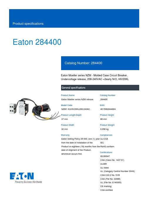
Eaton 284400Eaton Moeller series NZM - Molded Case Circuit Breaker. Undervoltage release, 208-240VAC +2early N/O, HIV20KLGeneral specificationsEaton Moeller series NZM release 284400NZM1-XUHIV20KL208-240AC 401508284400437 mm 66 mm 32 mm 0.056 kg Eaton Selling Policy 25-000, one (1) year from the date of installation of the Product or eighteen (18) months from the date of shipment of the Product, whichever occurs first.UL/CSA IECRoHS conformIEC60947CSA (Class No. 1437-01) UL489 UL listedUL (Category Control Number DIHS) CSA-C22.2 No. 5-09 CSA (File No. 22086) UL (File No. E140305) CE marking CSA certifiedProduct NameCatalog Number Model CodeEANProduct Length/Depth Product Height Product Width Product Weight WarrantyCompliancesCertificationsIs the panel builder's responsibility. The specifications for the switchgear must be observed.208 VMeets the product standard's requirements.10 msIs the panel builder's responsibility. The specifications for the switchgear must be observed.Does not apply, since the entire switchgear needs to be evaluated.1.5 VAMeets the product standard's requirements.0 VTwo separate early-make auxiliary contacts0.8 W240 VIs the panel builder's responsibility.15 ms eaton-feerum-the-whole-grain-solution-success-story-en-us.pdf eaton-digital-nzm-brochure-br013003en-en-us.pdfeaton-digital-nzm-catalog-ca013003en-en-us.pdfDA-DC-03_NZM1eaton-circuit-breaker-release-nzm-mccb-dimensions.eps eaton-circuit-breaker-contact-nzm-mccb-3d-drawing-004.epsM1-XUHIV20KL208-240ACIL01203002ZIntroduction of the new digital circuit breaker NZMThe new digital NZM RangeProduct Data Sheet - 284400eaton-nzm-technical-information-sheet10.11 Short-circuit ratingRated control supply voltage (Us) at AC, 50 Hz - min 10.4 Clearances and creepage distancesMinimum command time - min10.12 Electromagnetic compatibility10.2.5 LiftingPick-up power consumption at AC (undervoltage release) 10.2.3.1 Verification of thermal stability of enclosures Rated control supply voltage (Us) at DC - minFitted with:Pick-up power consumption at DC (undervoltage release) Rated control supply voltage (Us) at AC, 50 Hz - max 10.8 Connections for external conductorsMinimum command time - maxSpecial features BrochuresCatalogsCertification reports DrawingseCAD modelInstallation instructions Installation videos Specifications and datasheets Technical data sheetsUndervoltage release with 2 early-make auxiliary contacts, e.g., for early-make connection ofundervoltage release inmain switch applications, aswell as for interlock and loadshedding circuits.For use with emergency-stop devices in connectionwith an emergency-stopbutton.When the under-voltage tripis switched off, accidentalcontact with the circuitbreaker’s primary contacts isprevented when switchedon.Early make of auxiliarycontacts on switching onand off (manual operation):approx. 20 msCannot be used inconjunction with NZM...-XR... remote operator.Undervoltage releasescannot be installedsimultaneously with NZM...-XHIV... early-make auxiliarycontact or NZM...-XA...shunt release.Rated control supply voltage (Us) at DC - max0 V10.9.3 Impulse withstand voltageIs the panel builder's responsibility.Rated control supply voltage208 - 240 V 50/60 Hz10.6 Incorporation of switching devices and components Does not apply, since the entire switchgear needs to be evaluated.10.5 Protection against electric shockDoes not apply, since the entire switchgear needs to be evaluated.Used withNZM1(-4), N(S)1(-4)Electric connection typeScrew connection10.13 Mechanical functionThe device meets the requirements, provided the information in the instruction leaflet (IL) is observed.10.2.6 Mechanical impactDoes not apply, since the entire switchgear needs to be evaluated.10.9.4 Testing of enclosures made of insulating materialIs the panel builder's responsibility.Number of contacts (normally closed contacts)10.3 Degree of protection of assembliesDoes not apply, since the entire switchgear needs to be evaluated.Voltage typeACDrop-out voltage of undervoltage release AC/DC - min0.35 x UsFrameNZM1Reaction time19 msSuitable forOff-load switchVoltage tolerance - min.85Rated control voltage (relay contacts)240 V AC208 V ACPower consumption0.8 W (sealing DC)1.5 VA (sealing AC)10.2.3.2 Verification of resistance of insulating materials to normal heatMeets the product standard's requirements.Drop-out voltage of undervoltage release AC/DC - max0.7 x Us10.2.3.3 Resist. of insul. mat. to abnormal heat/fire by internal elect. effectsMeets the product standard's requirements.Connection typeAuxiliary contact terminals with 3 m of loose connection cables Coil terminals wired to terminal block10.9.2 Power-frequency electric strengthIs the panel builder's responsibility.Voltage tolerance - max1.1Undelayed short-circuit release - min0 ARated control supply voltage (Us) at AC, 60 Hz - min208 V10.7 Internal electrical circuits and connectionsIs the panel builder's responsibility.Terminal capacity (solid/flexible conductor)18 - 14 AWG (1x) at shunt release0.75 mm² - 2.5 mm² (2x) at shunt release with ferrule18 - 14 AWG (2x) for undervoltage releases, off-delayed0.75 mm² - 2.5 mm² (2x) for undervoltage releases, off-delayed with ferrule18 - 14 AWG (2x) at shunt release18 - 14 AWG (1x) for undervoltage releases, off-delayed0.75 mm² - 2.5 mm² (1x) for undervoltage releases, off-delayed with ferrule0.75 mm² - 2.5 mm² (1x) at shunt release with ferruleConnectionScrew10.10 Temperature riseThe panel builder is responsible for the temperature rise calculation. Eaton will provide heat dissipation data for the devices.TypeAccessoryUndervoltage release withearly-make auxiliary contact10.2.2 Corrosion resistanceMeets the product standard's requirements.10.2.4 Resistance to ultra-violet (UV) radiationMeets the product standard's requirements.10.2.7 InscriptionsMeets the product standard's requirements.Eaton Corporation plc Eaton House30 Pembroke Road Dublin 4, Ireland © 2023 Eaton. All Rights Reserved. Eaton is a registered trademark.All other trademarks areproperty of their respectiveowners./socialmedia240 V20 ARated control supply voltage (Us) at AC, 60 Hz - max Number of contacts (normally open contacts)Undelayed short-circuit release - max Number of contacts (change-over contacts)。
RB152中文资料
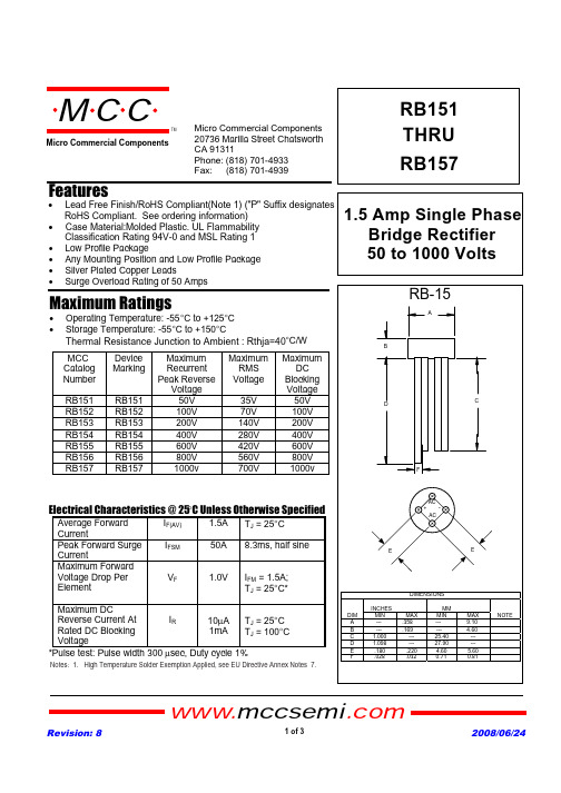
Figure 3 Forward Derating Curve
1.8
Figure 4 Peak Forward Surge Current
0 12
4 6 8 10 20
40 60 80 100
Cycles
Peak Forward Surge Current - Amperesversus Number Of Cycles At 60Hz - Cycles
Revision: 8
2 of 3
2008/06/24
60
1.5
1.2
0.9 Amps
0.6
50 40 30 Amps 20 10
0.3 Single Phase, Half Wave 60Hz Resistive or Inductive Load
00
25
50
75 100 125 150
Average Forward Rectified Current - Amperes versus Case Temperature - qC
50V 100V 200V 400V 600V 800V 1000v
Maximum RMS
Voltage
35V 70V 140V 280V 420V 560V 700V
Maximum DC
Blocking Voltage
50V 100V 200V 400V 600V 800V 1000v
1.5 Amp Single Phase Bridge Rectifier 50 to 1000 Volts
AZM 161 商品说明书
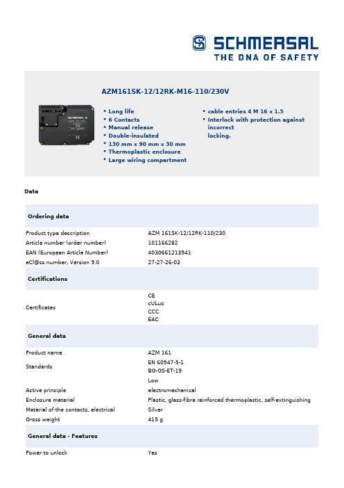
DataOrdering dataProduct type descriptionAZM 161SK-12/12RK-110/230Article number (order number)101166282EAN (European Article Number)4030661213941eCl@ss number, Version 9.027-27-26-03CertificationsCertificates CEcULusCCC EACGeneral dataProduct nameAZM 161Standards EN 60947-5-1BG-GS-ET-19LowActive principleelectromechanical Enclosure materialPlastic, glass-fibre reinforced thermoplastic, self-extinguishing Material of the contacts, electricalSilver Gross weight 415 g General data - FeaturesPower to unlock Yes AZM161SK-12/12RK-M16-110/230VLong life6 ContactsManual releaseDouble-insulated130 mm x 90 mm x 30 mmThermoplastic enclosureLarge wiring compartment cable entries 4 M 16 x 1.5Interlock with protection against incorrect locking.Manual release YesNumber of actuating directions3Number of auxiliary contacts2Number of safety contacts4Safety appraisalStandards ISO 13849-1Mission Time20 Year(s)Safety appraisal - Safety outputsB10d Normally-closed contact (NC)2,000,000 Operations B10d Normally open contact (NO)1,000,000 OperationsMechanical dataMechanical life, minimum1,000,000 Operations Actuating play in direction of actuation 5.5 mmClamping force in accordance with ISO14119F zh2,000 NLatching force30 Npositive break travel10 mmPositive break force, minimum20 NActuating speed, maximum 2 m/sMechanical data - Connection techniqueTerminal Connector Screw terminals Cable section, minimum 1 x 0.25 mm²Cable section, maximum 1 x 1.5 mm²Note (Cable section)All indications about the cable section are including the conductor ferrules.Mechanical data - DimensionsHeight of sensor90 mmLength of sensor30 mmWidth of sensor130 mmAmbient conditionsProtection class IP 67 to IEC/EN 60529 Ambient temperature, minimum-25 °CAmbient temperature, maximum+60 °CAmbient conditions - Insulation valueRated impulse withstand voltage 4 kVElectrical dataThermal test current 6 ARated control voltage230 VACRequired rated short-circuit current to EN60947-5-11,000 AElectrical power consumption, maximum10 WSwitching element NO contact, NC contact Switching principle Creep circuit element Switching frequency1,000 /hOther dataNote (applications)sliding safety guard removable guard hinged safety guardScope of deliveryIncluded in delivery Actuators must be ordered separately. NotesNote (Manual release)For maintenance, installation, etc.For manual release using M5 triangular key, available as accessoryOrdering codeProduct type description:AZM 161 (1)-(2)(3)K(4)-(5)-(6)(7)(1)SK Screw connectionCC Cage clampsST Connector M12, 8 and 4 pole (only for Us: 24 VAC/DC)(2)12/12 2 NO contacts/4 NC contacts12/11 2 NO contacts / 3 NC contacts (conector version)11/12 2 NO contacts / 3 NC contacts (conector version)(3)without Latching force 5 NR Latching force 30 N(4)without Power to unlockA Power to lock(5)without Lateral manual releaseED Manual release on the cover sideEU Manual release on the rear sideT Lateral emergency exitTD Emergency exit on the cover sideTU Emergency exit on the rear sideN Emergency release(6)024Us: 24 VAC/DC110/230Us: 110/230 VAC(7)G with LED (only for Us: 24 VAC/DC)PicturesProduct picture (catalogue individual photo)ID: kazm1f03| 36,6 kB | .png | 74.083 x 55.739 mm - 210 x 158Pixel - 72 dpi| 60,1 kB | .jpg | 22.831 x 17.195 mm - 320 x 241 Pixel- 356 dpi| 698,5 kB | .jpg | 352.778 x 265.289 mm - 1000 x 752Pixel - 72 dpiProduct picture (catalogue individual photo)ID: sazm1f03| 364,3 kB | .jpg | 352.778 x 265.289 mm - 1000 x 752Pixel - 72 dpi| 25,3 kB | .png | 74.083 x 55.739 mm - 210 x 158Pixel - 72 dpi| 38,1 kB | .jpg | 22.831 x 17.195 mm - 320 x 241 Pixel- 356 dpiDimensional drawing basic componentID: kazm1g09| 4,5 kB | .png | 74.083 x 62.442 mm - 210 x 177 Pixel- 72 dpi| 139,6 kB | .jpg | 352.778 x 298.097 mm - 1000 x 845Pixel - 72 dpi| 34,7 kB | .jpg | 112.889 x 95.25 mm - 320 x 270 Pixel- 72 dpi| 137,3 kB | .cdr |Switch travel diagramID: kazm1s07| 28,7 kB | .jpg | 112.889 x 97.367 mm - 320 x 276Pixel - 72 dpi| 17,7 kB | .cdr || 2,9 kB | .png | 74.083 x 63.853 mm - 210 x 181 Pixel- 72 dpiDiagramID: kazm1k29| 30,4 kB | .jpg | 112.889 x 72.672 mm - 320 x 206Pixel - 72 dpiOperating principleID: kazm1a41| 48,4 kB | .cdr |K.A. Schmersal GmbH & Co. KG, Möddinghofe 3, D-42279 WuppertalThe details and data referred to have been carefully checked. Images may diverge from original. Further technical data can be found in the manual. Technical amendments and errors possible.Generated on 08.07.2020 18:51:13。
CSC-161说明书(0SF.451.033)_V1.01

第二篇 用户安装使用 .................................................. 26
4 开箱检查 ........................................................... 26
5 整定值及整定计算说明 ............................................... 26
3 装置软件 ........................................................... 10
3.1 保护程序整体结构................................................................................................ 10 3.2 启动元件................................................................................................................ 10 3.3 选相元件................................................................................................................ 11 3.4 距离保护................................................................................................................ 11 3.5 TV 断线后的两段过流保护................................................................................... 14 3.6 零序电流保护........................................................................................................ 15 3.7 过电流保护............................................................................................................ 15 3.8 过负荷保护............................................................................................................ 16 3.9 低周减载功能........................................................................................................ 16 3.10 低压减载功能...................................................................................................... 17 3.11 三相一次重合闸.................................................................................................. 17 3.12 断路器失灵启动电流元件.................................................................................. 18 3.13 反时限保护.......................................................................................................... 18 3.14 慢速重合闸功能.................................................................................................. 18 3.15 异常检测和判别.................................................................................................. 18 3.16 保护逻辑框图 ....................................................................................................... 21
电磁炉用功率管的型号 代换 参数

电磁炉用功率管的型号代换参数2007年07月28日星期六 12:05大量维修实践表明,电磁炉(灶)内的部分元器件因工作温度较高,工作电流较大,电压较高等,其故障或损坏概率也较高。
其中的场效应功率管损坏率最高。
但由于商业竞争激烈,一般都不随机附带图纸,加之电磁炉所采用的场效应功率管一般均为较新产品,这便给维修带来不便和困难。
下面笔者根据汇集来的相关资料,提供几种常用电磁炉场效应功率管及代换资料供参考。
电磁炉一般均采用N型沟道功率场效应管,其相关参数为BVCBO≥1600V,BVCEO≥1000V,PCM≥100W,ICM≥7A,HFE≥40。
常用的电磁炉用场效应管内部带阻尼二极管的型号有 GT40N150D、GT40T301、SEC·G40N150D、ZON120ND、GT40T101、SQD35JA等。
内部不带阻尼二极管的型号有BT40T101、SGL40N150/150D等。
在维修代换时,若采用不带阻尼二极管的功率场效应管,应在D、S极间加接一只阻尼二极管,该二极管必须是快恢复型阻尼二极管,其耐压应≥1500V。
加接时正极接S 极,负极接D极即可。
参考型号如S5J53、 BY4591500等。
在负载电磁线圈和功率管之间串一只100W的灯泡再通电试机,可以防止烧管。
GT40Q321,FGL40N150D, FGL60N170D, FGA25N120,SK25N120,G40N150D, FGA25N135,1MBH25D--120,GP20B120UD--E,IXGH20N120BDI,以上功率管内部都带阻尼管,耐压都在1200V以上电流在20A以上只要电流相差不多都可以互相代换。
SGW25N120,K15T120。
以上的管子内部不带阻尼,如果要代换一上功率管时可以在电路板上安装2个以上的阻尼二极管耐压1200V以上,电流在8A以上。
电磁炉的关键元器件介绍1、大功率管IGBT(H20T120)说明:(1)、IGBT为电磁炉电路控制核心元器件,使用温度为小于85℃。
RB1电源保护设备用户手册说明书

IMPORT ANT SAFETY INSTRUCTIONSWARNING: When using electric products, basic cautions should always be followed, including the following.1. Read all safety and operating instructions before using this product2. The product should be powered by a three pin `grounded (or earthed) plug connected to a power socket with a grounded earth outlet.3. All safety and operating instructions should be retained for future reference4. Obey all cautions in the Operating instructions and on the back of the unit5. All operating instructions should be followed6. This product should not be used near water, i.e. a bathtub, sink, swimming pool, wet basement, etc.7. This product should be located so that its position does not interfere with its proper ventilation. It should not be placed flat against a wall or placed in a built up enclosure that will impede the flow of cooling air.8. This product should not be placed near a source of heat such as stove, radiator, or another heat producing amplifier.9. Connect only to a power supply of the type marker on the unit adjacent to the power supply cord.10.Never break off the ground pin on a power supply cord.11.Power supply cords should always be handled carefully. Never walk or place equipment on power supply cords. Periodically check cords for cuts or signs of stress, especially at the plug and the point where the chord exits the unit.12.The power supply cord should be unplugged when the unit is to be unused for long periods of time.13.If this product is to be mounted in an equipment rack, rear support should be provided.14.The user should allow easy access to any mains plug, mains coupler and mains switch used in conjunction with this unit thus making it readily operable.15.Metal parts can be cleaned with a damp cloth. The vinyl covering used on some units can be cleaned with a damp cloth or ammonia based household cleaner if necessary. Disconnect the unit from the power supply before cleaning.16.Care should be taken so that objects do not fall and liquids are not spilled into the unit through any ventilation holes or openings. On no account place drinks on the unit.17. A qualified service technician should check the unit if:18.The user should not attempt to service the equipment. All service work is done by a qualified service technician.19. Exposure to extremely high noise levels may cause a permanent hearing gloss. Individuals vary considerably in susceptibility to noise induced hearing loss, but nearly everyone will lose some hearing if exposed to sufficiently intense noise for a sufficient time. The U.S. Government's Occupational Safety and Health Administration (OSHA) has specified the following permissible noise level exposure. Duration Per Day In Hours Sound Level dBA, slow response8 9069249539721001 ½1021105½110¼ or less 115According to OSHA, any exposure in excess of the above permissible limits could result in some hearing loss. Ear plugs or protectors in the ear canals or over the ears must beworn when operating this amplification system in order to prevent a permanent hearing loss if exposure exceeds the limits set forth above. T o ensure against potentially dangerous exposure to high sound pressure levels it is recommended that all persons exposed to equipment capable of producing high sound pressure levels such as this amplification system be protected by hearing protectors while this unit is in operation.!The power cord has been damaged!Anything has fallen or spilled into the unit !The unit does not appear to operate correctly!The unit has been dropped or the enclosure damaged.BEFORE SWITCHING ONAfter unpacking your amplifier check that it is factory fitted with a three pin 'grounded' (or earthed) plug. Before plugging into the power supply ensure you are connecting to a grounded earth outlet.If you should wish to change the factory fitted plug yourself, ensure that the wiring convention applicable to the country where the amplifier is to be used is strictly conformed to. A s an example in the United Kingdom the cable colour code for connections are as follows.NOTEThis manual has been written for easy access of information. The front and rear panels are graphically illustrated, with each control and feature numbered. For a description of the function of each control feature, simply check the number with the explanations adjacent to each panel.Y our Laney amplifier has undergone a thorough two stage, pre-delivery inspection, involving actual play testing.When you first receive your Laney Bass amp, follow these simple procedures:(i) Ensure that the amplifier is the correct voltage for the country it is to be used in.(ii) Connect your instrument with a high quality shielded instrument cable. Y ou have probably spent con siderable money on your amplifier and guitar - don’t use poor quality cable it won’t do your gear justice.Please retain your original carton and packaging so in the unlikely event that some time in the future your amplifier should require servicing you will be able to return it to your dealer securely packed.Care of your Laney amplifier will prolong it's life.....and yours!EARTH OR GROUND - GREEN/YELLOW NEUTRAL - BLUELIVE - BROWNINTRODUCTIONThe RB1 is a 15W Bass combo with an 8 inch loudspeaker in a sturdy wooden cabinet. Its features include; a ¼” jack input, a gain control and a switchable compressor, a flexible EQ system with Bass, Middle, T reble, and an overall Volume control. Should you need to play along to a CD/MP3, you can plug the output of your player into the CD/Line in Socket. A headphone socket is also provided for private practice sessions.An explanation of these features follows on pages 6-8.Dear Player,Thank you very much for purchasing your new Laney product and becoming part of the worldwide Laney family. Each and every Laney unit is designed and built with the utmost attention to care and detail, so I trust yours will give you many years of ney products have a heritage which stretches back to 1967 when I first began building valve amplifiers in my parent’s garage. Since then we have moved on from strength to strength developing an extensive range of guitar, bass, public address and keyboard amplification products along with a list of Laney endorsees that includes some of the world’s most famous and respected musicians. At the same time we believe we have not lost sight of the reason Laney was founded in the first place - a dedication to building great sounding amplification for working musicians. Warm Regards,Lyndon Laney CEOInput socket for connection of bass guitars. The socket will accommodate High or Low output basses, either Active or pressor is an LED to indicate when the compressor is active. The higher the setting the more compression. to have the compressor engaged but it only be active during certain periods of playing - typically the most dynamic sections.This control is used to set the level of gain present in the pre-amp. producing distortion. The Gain control should be used in conjunction with the characteristics.Controls the boost and cut of the low-frequency response of the pre-amplifier. Controls the boost and cut of the mid-frequency response of the pre-amplifier. Controls the boost and cut of the high-frequency response of the pre-amplifier. Sets the overall listening level of the amplifier.Stereo jack socket provided for connecting an external sound source such as; CD players, MP3 players, Minidisc etc.Socket for connecting headphones, With headphones connected, the internal loudspeaker is automatically switched off.Indicates power is connected and the amp is switched on. (Always switch off and disconnect power cord when not in use)Main power on/off switchANEL CONTROLSPower inlet socket. Connect to your power source. Make sure the specified voltage is correct for your country!Serial Number and model of your unit.REAR PBLOCK DIAGRAMSAMPLE SYSTEMPOWER TO THE MUSICLaneySPECIFICA TIONS Supply Voltage Mains Fuse~220V>@240V = T2A L. ~100>~120V = T5A L (Time delay)Power Consumption 30W Output Power Rating 15WLoudspeaker 8” Custom Designed DriverFeatures Switchable Compressor with Activity light. Clip distortion limiter.EQ Bass (±8dBu at 40Hz)Middle (Input Impedance 1M Ohm/100pF Size375*364*260(H*W*D)Unit Weight 9.5 Kg Packing Weight11 Kg~100V , ~120V , ~220V , ~230V , ~240V 50/60Hz Factory Option ±8dBu at 800Hz)T reble (±8dBu at 3.5KHz)This product conforms to :European EMC directive(2004/108/EC), LowVoltage Directive (72/23/EEC) and CE mark Directive (93/68/EEC)。
华为AR G3系列企业路由器介绍P

软件规格描述 以太网,CE1/CT1,E1/T1,E3,ADSL2+,G.SHDSL,同异步串口,ISDN,CPOS, POS
IEEE802.1P,IEEE 802.1Q,IEEE 802.3 ,VLAN管理,MAC管理,MSTP,SEP
DHCP server/client/relay,PPPoE server/client,PPPoA server/client,PPPoEoA server/client,NAT,子接 口管理 RTP协议,SIP协议,SIP AG,IP PBX/TDM PBX,FXO/FXS,VoIP/电话会议,BEST,DISA,SBC AP设备管理(AC发现/AP接入/AP管理),CAPWAP协议, WLAN 用户管理,WLAN射频管理(802.11a/ b/g/n/ac),WLAN QoS(WMM),WLAN 安全(WEP/WPA/WPA2/密钥管理)
规格名称 转发性能 防火墙性能 (1500字节) 二层交换容量 IPSec隧道数
固定接口
SIC插槽 WSIC插槽 (缺省/最大**) XSIC插槽 (缺省/最大**) DSP插槽 USB2.0端口 内存容量 (缺省/最大)
AR2201-48FE 1Mpps
AR2204-27GE 2Mpps
900Mbps
ACL,基于域的状态防火墙,802.1x认证,MAC认证,Portal认证,AAA,RADIUS,HWTACACS, 广播风暴抑制,ARP安全,ICMP反攻击,URPF,IP Source Guard,DHCP Snooping,CPCAR,黑名 单,攻击源追踪,国密算法,上网行为管理,IPS,URL过滤,文件过滤
AR3260 系列
总部/大型分支 (>350人)
核外电子排布和元素周期律

镧系收缩造成的影响 对于镧系元素自身的影响,使 15 种镧系元素的半径相似, 性质相近,分离困难。
对于镧后元素的影响,使得第二、第三过渡系的同族元素半 径相近,性质相近,分离困难。
K Ca Sc r/pm 203 174 144
Ti V Cr 132 122 118
Rb Sr Y r/pm 216 191 162
每个 代表一个原子轨道 p 三重简并 d 五重简并 f 七重简并
(2) 屏蔽效应
以 Li 原子为例说明这个问题 : 研究外层的一个电子。 它受到核的 的引力,同时又受到内层电子的 -2 的斥力。
实际上受到的引力已经不会恰好是 + 3 ,受到的斥力也不会恰 好是 - 2 ,很复杂。
我们把
看成是一个整体,即被中和掉部分正电的
K Potassium Ca Calcium Sc Scandium Ti Titanium V Vanadium Cr Chromium Mn Manganese Fe Iron Co Cobalt Ni Nickel
钾
[Ar] 4s1
钙
[Ar] 4s2
钪
[Ar] 3d14s2
钛 [Ar] 3d24s2
eV
在多电子体系中,核外其它电子抵消部分核电荷,使被讨论 的电子受到的核的作用变小。这种作用称为其它电子对被讨论电 子的屏蔽效应。
受到屏蔽作用的大小,因电子的角量子数 l 的不同而不同。 4s ,4p ,4d ,4f 受到其它电子的屏蔽作用依次增大,故有
E4s < E4p < E 4d < E 4f
3 个能级 4s 3d 4p 9 个轨道
5 Rb Sr Y Zr Nb Mo Tc Ru Rh Pd Ag Cd In Sn Sb Te I Xe
- 1、下载文档前请自行甄别文档内容的完整性,平台不提供额外的编辑、内容补充、找答案等附加服务。
- 2、"仅部分预览"的文档,不可在线预览部分如存在完整性等问题,可反馈申请退款(可完整预览的文档不适用该条件!)。
- 3、如文档侵犯您的权益,请联系客服反馈,我们会尽快为您处理(人工客服工作时间:9:00-18:30)。
10
5 AVE:13.6A 0 IFSM DISRESION MAP
trr DISPERSION MAP
20
30
1000
Mounted on epoxy board
TRANSIENT THAERMAL IMPEDANCE:Rth (℃/W)
IM=10mA time
IF=0.2A
PEAK SURGE FORWARD CURRENT:IFSM(A)
REVERSE CURRENT:IR(uA)
Ta=25℃ IF=0.7A n=30pcs
410 400 390 380 AVE:386.8mV 370 VF DISPERSION MAP
Ta=25℃ VF=1A n=30pcs
900 800 700 600 500 400 300 200 100 0 AVE:205.9uA
元器件交易网
RB161VA-20
Diodes
Schottky barrier diode
RB161VA-20
Applications General rectification Features 1) Small power mold type (TUMD2) 2) Low VF 3) High reliability External dimensions (Unit : mm)
0
25 50 75 100 AMBIENT TEMPERATURE:Ta(℃) Derating Curve゙(Io-Ta)
125
3
AVERAGE RECTIFIED FORWARD CURRENT:Io(A)
2.5 2 1.5 1 0.5 Sin(θ=180) 0 0 25 50 DC
0A 0V
Io t T VR D=t/T VR=10V Tj=125℃
0.17±0.1 0.05 1.3±0.05
Land size figure (Unit : mm)
1.1
1.9±0.1
2.5±0.2
TUMD2
Structure Silicon epitaxial planar
0.8±0.05
Structure
0.6±0.2
ROHM : TUMD2 0.1 dot (year week factory) + day
Symbol VF1 VF2 IR
Min. -
Typ. 0.33 0.38 0.2
Max. 0.37 ons IF=700mA IF=1A VR=20V
0.8 0.5
2.0
1/3
元器件交易网
RB161VA-20
Diodes
Electrical characteristic (Ta=25°C)
Symbol VRM VR Io IFSM Tj Tstg
Limits 30 20 1 5 125 -40 to +125
Unit V V A A ℃ ℃
Parameter Forward voltage Reverse current
Electrical characteristic curves
1000 Ta=75℃ 100000 10000 1000 Ta=25℃ 100 Ta=-25℃ 10 1 0 5 10 15 20 25 REVERSE VOLTAGE:VR(V) VR-IR CHARACTERISTICS 30 Ta=125℃ 1000 f=1MHz
Reverse voltage (repetitive peak) Reverse voltage (DC) Average rectified forward current Forward current surge peak (60Hz・1cyc) Junction temperature Storage temperature
PEAK SURGE FORWARD CURRENT:IFSM(A)
Ifsm 15 8.3ms 8.3ms 1cyc
25 20 15 10 5 0
Ifsm t
1ms
Rth(j-a)
300us
10
100
Rth(j-c)
5
0 1 10 NUMBER OF CYCLES IFSM-CYCLE CHARACTERISTICS 100
1 0 10 20 REVERSE VOLTAGE:VR(V) VR-Ct CHARACTERISTICS 30
350
420
1000
FORWARD VOLTAGE:VF(mV)
FORWARD VOLTAGE:VF(mV)
340 330 320 310 AVE:332.9mV 300 VF DISPERSION MAP
CAPACITANCE BETWEEN TERMINALS:Ct(pF)
Ta=25℃ f=1MHz VR=0V n=10pcs
RESERVE RECOVERY TIME:trr(ns)
190
25 20 15 10 5 AVE:9.3ns 0
15
Ta=25℃ IF=0.5A IR=1A Irr=0.25*IR n=10pcs
REVERSE CURRENT:IR(uA)
FORWARD CURRENT:IF(A)
Ta=125℃ 100
Ta=75℃
CAPACITANCE BETWEEN TERMINALS:Ct(pF)
100
Ta=25℃ 10 Ta=-25℃
10
1 0 100 200 300 400 500 FORWARD VOLTAGE:VF(mV) VF-IF CHARACTERISTICS
D=1/2
75
100
125
CASE TEMPARATURE:Tc(℃) Derating Curve゙(Io-Tc)
3/3
元器件交易网
Appendix
Notes
No technical content pages of this document may be reproduced in any form or transmitted by any means without prior permission of ROHM CO.,LTD. The contents described herein are subject to change without notice. The specifications for the product described in this document are for reference only. Upon actual use, therefore, please request that specifications to be separately delivered. Application circuit diagrams and circuit constants contained herein are shown as examples of standard use and operation. Please pay careful attention to the peripheral conditions when designing circuits and deciding upon circuit constants in the set. Any data, including, but not limited to application circuit diagrams information, described herein are intended only as illustrations of such devices and not as the specifications for such devices. ROHM CO.,LTD. disclaims any warranty that any use of such devices shall be free from infringement of any third party's intellectual property rights or other proprietary rights, and further, assumes no liability of whatsoever nature in the event of any such infringement, or arising from or connected with or related to the use of such devices. Upon the sale of any such devices, other than for buyer's right to use such devices itself, resell or otherwise dispose of the same, no express or implied right or license to practice or commercially exploit any intellectual property rights or other proprietary rights owned or controlled by ROHM CO., LTD. is granted to any such buyer. Products listed in this document are no antiradiation design.
0A 0V
Io t T VR D=t/T VR=10V Tj=125℃
0.6 0.4 0.2 0 0
Sin(θ=180)
D=1/2
0 0.5 1 1.5 AVERAGE RECTIFIED FORWARD CURRENT:Io(A) Io-Pf CHARACTERISTICS 2 0 10 20 REVERSE VOLTAGE:VR(V) VR-PR CHARACTERISTICS 30
