78LMT-USB3 Rev.3.1
AM3KA538用户手册说明书
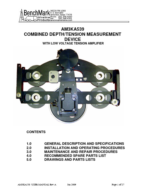
AM3KA539COMBINED DEPTH/TENSION MEASUREMENTDEVICEWITH LOW VOLTAGE TENSION AMPLIFIERCONTENTSDESCRIPTION AND SPECIFICATIONS1.0 GENERAL2.0 INSTALLATIONOPERATING PROCEDURESANDREPAIR PROCEDURES3.0 MAINTENANCEAND4.0 RECOMMENDED SPARE PARTS LIST5.0 DRAWINGS AND PARTS LISTS1.0 GENERAL DESCRIPTION AND SPECIFICATIONSThe BenchMark Measurement System AM3K measuring device combines in one compact, lightweight unit, both depth measurement and line tensionmeasurement capabilities. A single measuring wheel is used to drive anoptical encoder. An electronic load axle is used to measure line tension.MEASUREMENT1.1 DEPTHThe AM3K uses a single measuring wheel to measure the amount ofwireline moving to and from the borehole. The measuring wheel is coupled to an encoder that transmits electrical signals via a cable to the hoistman’spanel and/or logging computer representing cable travel. An independentlypowered encoder and display panel is used for back up depth indication.The hardened measuring wheel has a 2.0000 ft. (609.600 mm)circumference with a 3/8" groove. A spring mounted tension roller is used to hold the measuring wheel in contact with the wireline.Two guide rollers are used to properly hold the cable in line with themeasuring wheel. Wear blocks are also used to guide the cable and prohibit cable contact with the frame members. The frame members are anodized aluminum.6061-T6MEASUREMENT1.2 TENSIONThe AM3K uses an electronic load axle on the measuring wheel to measureline tension. Three wheels are used to create a force on the load axle normal to the axis of the wireline. To generate this force the wheel mounted on theload axle is offset from the other two slightly. This offset creates a slight bend in the cable.As wireline tension increases the small offset creates a correspondingbending force on the strain-gauged load axle. An electronic signal istransmitted via cable to the hoistman’s panel and/or logging computertension. A calibrate resistor is included in the load pin to wirelinerepresentingsend out a signal to calibrate the computer system.SPECIFICATIONS1.3 GENERAL13.6kglbs30WEIGHT:mm500 LENGTH:19.6”mm343 HEIGHT: 13.5”mm WIDTH: 8.2”208 CABLE BEND OVER TENSION WHEEL: < 10 DegreesMAXIMUM LINE TENSION: 10,000 lbs 4538 kgMEASURING WHEEL CIRCUMFERENCE 24.000” 609.60 mmWHEELCIRCUMFERENCE WITH CABLE INSTALLEDMEASURING3/16” cable – 2.015 ft7/32" cable - 2.017 ft.1/4” cable – 2.020 ft.9/32" cable – 2023 ft.5/16" cable - 2.026 ft.3/8" cable – 2.031 ft.SPECIFICATIONS1.4 TENSIONPower Requirements: 9 – 15 vdc excitationInterface: Strain Gauge bridge with 6 pin connectoron load pinTemperature stability: <= .015% full scale / deg F on zero<= .02% full scale / deg F on outputAccuracy: Within 150 lbs or 3% of actual, whichever isgreaterkglbs4536 Maximumload: 10,000Signal Output (w 5/16” cable)10,000lbs=72mv@12vexcitationShunt cal = 36 mv @ 12v excitation = 5000 lbs Multipliers for different sizes of cable3/16” cable – 1.457/32" cable – 1.381.22–cable1/4”–1.089/32"cable5/16" cable – 1.00.85–3/8"cable2.0 INSTALLATION AND OPERATING PROCEDURES2.1 SPOOLING ARM INSTALLATIONInstall the measuring head on to the spooling arm by using either the topadapter mount assembly to mount to an overhead spooling arm or the lower yoke floor mount assembly to mount to a floor mounted pedestal.Following are some of the mount options:2.1.1 AM3KA243 OVERHEAD MOUNT FOR 40MM SINGLE BAR(ASEP SPOOLER)AM3KA243 PARTS LISTNUMBER DESCRIPTION QTY ITEM PART1 AM3KM124 HOUSING BRG FLANGE 40MM ASEP 22 AM3KM138 HUB GUIDE ASEP OH ARM 13 AM3KM139 HUB GUIDE INNER ASEP OH ARM 24 AM3KM140 SPACER GUIDE ASEP OH ARM 15 AM3KM155 PLATE SIDE PIVOT ASEP OH ARM 26 AM3KM141 PLATE CHAIN GUIDE ASEP OH ARM 1AUTO SPOOL ASEP OH ARM 27 AM3KM143 ADAPTER10 AM3KM144 BEARING FLANGE 2 IN ID MOD 2LINEAR 40MMID X 50MMOD 212 AMSLP088 BEARING15 AM3KP044 SCREW 1/2-13 X 3.25 SOC HD SST 216 AM5KP042 SCREW 1/2-13 X 3/4 SOC HD SST 617 AM5KP080 SCREW 3/8-16 X 3/4 SOC HD SST 418 AMS1P046 SCREW 5/16-18 X 1 SHCS SST 819 AM3KP057 SCREW 5/16-18 X 1-1/4 SOC HD 220 AMS1P049 SCREW 1/4-20 X 2-1/4 SOC HD SS 221 AM3KP058 SCREW 10-24 X 1-1/4 SHCS SST 3SS 21/2"-1323 AMS1P065 NUT24 AM3KP059 NUT 10-24 ELASTIC STOP SST 325 C276P037 WASHER 1/2 FLAT SST 426 AMS1P047 WASHER 5/16 LOCK SS 827 AMS1P066 WASHER 1/2 LOCK SS 228 C276P036 WASHER 1/4 LOCK SS 229 ACMU2P31 WASHER 1/4 FLAT SS 230 AMS1P054 WASHER #10 FLAT SS 62.1.2 AM3KA241 OVERHEAD MOUNT USING 2X3 RECTANGULAR TUBINGNUMBER DESCRIPTION QTY ITEM PART1 AM3KM055 PLATE SIDE PIVOT OH ARM 3 WHL 22 AM3KM019 PIVOT WELDMT SPOOL ARM RECT 2X3X15 DEG 13 AM3KM117 SHAFT PIVOT SPOOLING ARM 10 IN 14 AMS1P009 RETAINING PIN (T HANDLE) 16 AM3KP045 BEARING BRZ FLANGED 27 263437000 ONE-PIECE CLAMP-ON COLLAR 18 231194000 BEARING FLANGE 1.25ID x 1.25LG 29 AM3KM142 BUSHING FLANGE QUIK PIN OH ARM 210 AM3KP044 SCREW 1/2-13 X 3.25 SOC HD SST 311 C276P037 WASHER 1/2 FLAT SST 412 AMS1P066 WASHER 1/2 LOCK SS 3SS 3 13 AMS1P065 NUT1/2"-1314 AM5KP075 CHAIN SASH #35 SST 122.1.3 AM3KA242 OVERHEAD MOUNT USING 2" ROUND TUBINGNUMBER DESCRIPTION QTY ITEM PART1 AM3KM055 PLATE SIDE PIVOT OH ARM 3 WHL 22 AMS8M019 PIVOT WELDMT SPOOLING ARM RD 13 AM3KM117 SHAFT PIVOT SPOOLING ARM 10 IN 14 AMS1P009 RETAINING PIN (T HANDLE) 16 AM3KP045 BEARING BRZ FLANGED 27 263437000 ONE-PIECE CLAMP-ON COLLAR 18 231194000 BEARING FLANGE 1.25ID x 1.25LG 29 AM3KM142 BUSHING FLANGE QUIK PIN OH ARM C MOUNT SST 210 AM3KP044 SCREW 1/2-13 X 3.25 SOC HD SST 311 C276P037 WASHER 1/2 FLAT SST 412 AMS1P066 WASHER 1/2 LOCK SS 3SS 3 13 AMS1P065 NUT1/2"-1314 AM5KP075 CHAIN SASH #35 SST 122.1.4 AM3KA244 OVERHEAD FLANGE MOUNTNUMBER DESCRIPTION QTY ITEM PART1 AM3KM055 PLATE SIDE PIVOT OH ARM 3 WHL 22 AM3KM238 YOKE PIVOT CENTER MOUNT SST 13 AM3KM217 SHAFT PIVOT SPOOLING ARM 7 IN 14 AMS1P009 RETAINING PIN (T HANDLE) 16 AM3KP045 BEARING BRZ FLANGED 1/2ID X 27 263437000 ONE-PIECE CLAMP-ON COLLAR ST S 18 231194000 BEARING FLANGE 1.25ID x 1.25LG 29 AM3KM142 BUSHING FLANGE QUIK PIN OH ARM 210 AM3KP044 SCREW 1/2-13 X 3.25 SOC HD SST 311 C276P037 WASHER 1/2 FLAT SST 412 AMS1P066 WASHER 1/2 LOCK SS 3SS 31/2"-1313 AMS1P065 NUT14 AM5KP075 CHAIN SASH #35 SST 122.1.5 AM3KA240 BOTTOM PEDASTAL MOUNTITEM PARTNUMBER DESCRIPTION QTY 1 AM3KM130-1 PLATE SIDE PIVOT LEFT UNIV 1SIDE PIVOT RIGHT UNIV 12 AM3KM130-2PLATE3 AM3KM029 SPACER SST 3/4 SIDE MT 3 WHEEL 24 AM3KP044 SCREW 1/2-13 X 3.25 SOC HD SST 45 C276P037 WASHER 1/2 FLAT SST 86 AMS1P066 WASHER 1/2 LOCK SS 47 AM3KM118 BUSHING PLAIN QR PIN BTM MT SS 28 AMS1P009 RETAINING PIN (T HANDLE) 19 AM5KP075 CHAIN SASH #35 SST 610 AM5KP040 SCREW 10-24 X 3/8 SOC HD SST 111 C276P035 WASHER #10 LOCK SS 1SS 41/2"-1312 AMS1P065 NUTINSTALLATION2.2 CABLETo install cable, remove the push pin, and hinge the head open. Nextinsert the cable, swing the head closed and reinsert the pin. Refer to picture.If under load, the load will need to be removed from the pin prior to removal.A “C” clamp can be used to remove the load.Make sure that the head can freely sit on the wireline. If the mountingarrangement will not let the head travel up and down freely and if the cableputs a upward or downward force on the measuring head, this force willcause an offset to the tension measurement which will result in an incorrect reading.tensionHEAD OPENED FOR CABLE INSTALLATION AND REMOVAL2.3 SYSTEM OPERATION2.3.1 Determine cable size to be used – 5/16” or 7/32”Since the wireline cable actually bends around the measuring wheel,the circumference of the wheel is affected by the size of the cable. Toaccurately measure depth, this needs to be taken into account byincreasing the size of the wheel. The bend radius of the wireline cablealso affects the tension measurement.These corrections are automatically made in the Kerr AMS4 Panels byselecting the proper cable size using the menu.To enter wheel size corrections directly, use the following wheel circumferences:3/16” cable – 2.015 ft.7/32" cable - 2.017 ft.1/4” cable – 2.020 ft.9/32" cable – 2023 ft.5/16" cable - 2.026 ft.3/8" cable – 2.031 ft.2.3.2 Install line in measuring head (refer to section 2.2).2.3.3 Make sure line is laying slack and head is free to move and hanginglevel. Press the Ten Zero Cal button and tension value should read 0.2.3.4 Press the Ten Cal button and tension should read 5000 lbs with 5/16"cable or 6200 lbs with 7/32" cable.2.3.5 Press the Zero Depth button to set the depth to zero when the tool ishanging at the zero point.2.3.6 At this point, the system is ready to log.3.0 MAINTENANCE AND REPAIR PROCEDURESCHECK3.1 PRE-JOBEach time the system is used perform the following steps:Verify that the AM3K is properly and securely attached to the spooling arm.Several different mounting kits are available for different types of spoolingarms.Verify that the depth measuring wheels are clean and that no groove hasbeen worn into the measuring wheel surface. Check the measuring andguide wheels for looseness, play, out-of-roundness, worn or rough sounding bearings, or other mechanical conditions that could affect measurementaccuracy. Ensure that the wheel bearings inner race is not spinning on theshaft and that the shaft is not spinning in the bushings.Verify that all fasteners are tight and that the ball lock pushpin is secure.Verify that the encoder, electronic load pin, and backup counter cable areinstalled and properly routed. Verify that the depth system is working byturning the wheel and observing the hoistman’s panel and backup displayunit to indicate cable movement. The hoistman's panel and backupdisplay should measure 2' for each rotation of the wheel.MAINTENANCE3.2 POST-JOBAt the completion of each job, thoroughly clean and dry the device as soon as possible. This avoids problems caused from borehole residues transferredfrom the wireline onto the measuring device. Borehole residues should bewashed from the device with a cleaning solvent such as Varsol or anequivalent type. Rinse the device with water, dry, and wipe down with an oily rag.Do not pressure washMAINTENANCE3.3 MONTHLYVisually inspect the interiors of the electrical connectors for the encoders and electronic load axle for dirt and evidence of insulation breakdown. Clean orreplace as necessary. Install dust caps on the connectors if the cables areremoved.Manually rotate each wheel by hand to verify its condition. Inspect the depth measuring wheels for signs of abnormal wear, diameter changes, orshaft/bearing play that can affect measurement accuracy. The wheel should be replaced if it is grooved more than .005". The wheel should be 7.639 /7.640" (194 mm) in diameter with a 24" circumference (609.6 mm). Inspectthe two grooved guide wheels on either side of the tension wheel. Theyshould be 4" (101.6 mm) in diameter (bottom of groove).Grease all the wheels and bearings that are fitted with a grease fitting (seefollowing diagram). Use a water proof, marine grade grease. An invertedgrease nozzle (Kerr p/n AM5KP130) is supplied with each head. This nozzle will fit any standard grease gun.3.4 ASSEMBLY / DISASSEMBLY PROCEDURES3.4.1 MEASURING WHEEL, SHAFT, AND BEARING REMOVALRemove encoder adapter and cover on opposite side.Remove both side plates.Remove wheel and axle assembly.Install new wheel and axle assembly with spacers.Reinstall side plates and encoder adapter and cover.It is recommended that the main bearings be replaced at this time.3.4.2 ELECTRONIC LOAD PIN REMOVALThe electronic load pin is held in place by one retaining ring on the outer end of its shaft. Remove the retaining ring. The load pin can then be removedfrom the mounting frame.3.4.3 BACKUP DEPTH PICKUP REMOVAL AND INSTALLATIONThe backup depth magnetic pickup is mounted to the encoder adapter. It isheld in place by four screws. Remove the screws and the pickup can then be removed. The pickup must be properly oriented to work correctly. The slotshould be oriented to the top. The top side is the encoder side. Ensure that an o-ring is inserted between the plastic housing and the mount. Anadditional o-ring is used between the connector and the housing to keepmoisture out.If the backup display is counting backward (i.e. counting negative when going downhole), simply rotate the pickup 180 degrees to change the direction.3.4.4 ENCODER COUPLING INSTALLATIONTo install the encoder coupling, first remove the plug in the encoder adapter.Install one of the metal parts of the three piece coupling to the wheel shaftand tighten it using a hex wrench. Next, install the center plastic piece on the wheel shaft coupling. Place the other metal coupling on the encoder shaftand set the encoder on the mount. Snug up the encoder coupling thenremove the encoder and tighten the coupling.Reinstall the encoder with o-rings and tighten it to the encoder mount. Next tighten the plug.4.0 RECOMMEND SPARE PARTS LISTDESCRIPTIONQTYP/N1 AM5KA137 ASSY WHEEL GUIDE 4 INCH COMPOSITEWITH BEARING1 AM5KA164 ASSY WHEEL TENSION FIXED 35MMWITH BEARING1 AM5KM157 BEARING BALL FAFNIR 207PP GREASEABLEtensionwheels)AM5KA164and(forAM5KA1371 AM3KA187 ROLLER ASSY PRESSURE 3/8" GROOVEWITH BEARING1 AM3KM002 BEARING BALL FAFNIR 200PP GREASEABLEroller)pressureMODAM3KA187(forMEASURING 2FT 3/8" GROOVEWHEEL1 AM3KA110ASSYshaft)(includes2 AMS1P003 BEARING BALL 204PP GREASABLE MOD(for measuring wheel)1 AM3KM050 ENCODER COUPLING ASSY WITH MAGNETS1 AM3KP203PIN ASSY LOW VOLTAGELOADPPREXENCODER12001 AM5KA079ASSYPICKUP1 AM5KA055MAGNETIC1 AMS1P009 RETAINING PIN (T HANDLE)NOZZLEGREASE1 AM5KP1305.0 DRAWINGS AND PARTS LISTS5.1 MEASURING HEAD DRAWINGSSIDE VIEWSIDE CUTAWAY VIEWDRUM END VIEWDRUM END CUTAWAY VIEWWELL END VIEWWELL END CUTAWAY VIEWTOP VIEWTOP CUTAWAY VIEWMEASURING HEAD PARTS LISTITEM PN DESCRIPTION QTY REF1 AM3KA131 FRAME ASSY UPPER 12 AM3KA132 FRAME ASSY LOWER 13 AM3KA148 ASSY PIVOT PRESS WHEEL W/GIDE 14 AM3KA240 KIT MOUNTING AM3K FLOOR 0 OPTION4 AM3KA241 KIT MOUNTING AM3K OVERHEAD ARM 2X3 RECT 0 OPTION4 AM3KA242 KIT MOUNTING AM3K OVERHEAD ARM 2IN ROUND 0 OPTION5 AM3KP203 ASSY LOAD AXLE LOW VOLTAGE 16 AM5KA079 ENCODER 1200 PPR EX 17 AM3KM040 ADAPTER ENCODER H25D/H20 MAG BACKUP 17 AM5KM057 ADAPTER ENCODER H37C/H25D 0 OPTION8 AM3KA121 PLATE SIDE ASSY W/PRESSURE WHL 29 AM3KM135 PLATE ORIENTATION LOAD PIN 110 AM5KM058 COVER ENCODER ADAPTER 111 AM5KM011 SHAFT TENSION ROLLER 30MM SST 414 AM5KM023 SHAFT PIVOT HORIZONTAL 1/2 SST 115 AM3KM023 SHAFT PIVOT PRESS ROLR 3/8 SST 117 AM3KA125 MOUNT ASSY PIVOT W/TIEDOWN 3K 118 AM3KM156 GUIDE REAR 3 WHEEL 119 AM5KA137 ASSY WHEEL GUIDE PLAS 35MM BRG 220 AM3KA001 ASSY WHEEL MEASURING 2' 3/8" GROOVE 122 AM3KA187 ROLLER ASSY PRESSURE 3/8" GROOVE 123 AM5KA164 ASSY WHEEL TENSN FIXD 35MM BRG 224 AM3KA236 LINK ASSY LOAD PIN W/SPHER BRG 125 AM3KM234 BLOCK WEAR 0.75 X 2.50 TOOLSTL W/10-24 HOLES 226 AM3KM064 PLATE WEAR 3/8 X 3/4 X 1-1/2 227 AM3KM154 SPOOL GUIDE REAR 3 WHEEL 128 AM3KM153 BUTTON GUIDE PRESS WHL PIVOT 0 REF29 AM3KM152 PLATE GUIDE PRESS WHL PIVOT 230 AM3KM115 BLOCK WEAR 232 AM5KA055 ASSY ENCODER BACKUP MAGNETIC 0 OPTION33 AM5KM084 SCREW ANTI-ROTATION TENS WHEEL 434 AM3KM052 BOLT SHOULDER 10MM OD SST 1/4-20 INT THD 135 AM3KM053 BOLT SHOULDER 5/16 X 1/4 MOD 136 AM3KM043 SPACER 10MMID X 0.57OD X 0.30W SST 137 AM3KM044 SPACER .31ID X 0.57OD X 0.175W SST 138 AM5KM155 BUSHING 35MM BRG W/ANTI-ROTATN 0 REF39 AM5KM039 SPACER 20MMID X 1.00OD X .197W PLASTIC 242 AM3KM049 GUIDE SPRING PRESS WHEEL 3 WHL 249 AM5KP019 BEARING BRZ FLANGED 1/2" ID OIL IMPRG 050 AM3KP009 BEARING BRZ FLANGED 3/8" ID OIL IMPRG 051 AM3KP032 BEARING BRZ .50ID X .625OD X .62 LONG 0 LOAD PIN LINK BRG52 AM3KP039 BEARING SPHERICAL 5/8" ID SELF LUBE SST 0 LOAD PIN LINK53 AMS1P003 BEARING BALL 20MM ID MOD W/HOLE 254 AM5KM157 BEARING BALL 35MM ID MOD GREASE HOLE 0 REF55 AM3KM002 BEARING BALL 10MM ID MOD GREASE HOLE 0 REF57 AM5KP075 CHAIN SASH #35 SST 658 AMS1P009 RETAINING PIN (T HANDLE) 159 AM3KP014 SPRING COMP 3-1/8 OAL 3/4 DIA SST 160 AM3KM050 COUPLING ENCDR W/BKUP MAGNETS 0 OPTION61 AMS1P090 COUPLING OLDHAM ENCODER 162 AM5KP071 O-RING 2-141 BUNA N H25 ENCDR 163 AMS1P014 O-RING 2-152 BUNA N ENC ADPTR 264 AM5KP067 DUST CAP CWL 065 AMS1P072 PLUG 3/8 NPT SS 166 AM5KP033 RING RETNG EXT 0.500 SHAFT SST 167 AM3KP018 RING RETNG EXT 1.188 SHAFT SST 868 AM3KP017 RING RETNG EXT 0.781 SHAFT SST 271 AMS1P006 RING RETNG INT UR187S 472 AM3KP048 RING RETNG EXT 0.375 E-RING SST 273 AM3KP015 RING RETNG INT UR-118S SST 074 AM5KP168 RING RETNG INT 2.875 LT DUTY .039 THICK SST 0 REF75 AM5KP043 SCREW 3/8-16 X 1/2 BUTTON HD SST 176 AM5KP038 SCREW 5/16-18 X 7/8 FH SOC SS 477 AM5KP045 SCREW 10-24 X 1/2 FH SOC SST 678 C276P031 SCREW 1/4-20 X 1-1/4 SOC HD SS 479 AMSLP025 SCREW 1/4-20 X 1 SOC HD SST 880 AMS1P049 SCREW 1/4-20 X 2-1/4 SOC HD SS 181 AM3KP054 SCREW 10-24 X 1 SHCS SST 482 AMS1P048 SCREW 1/4-20 X 3/4 SOC HD SST 483 AMSLP060 SCREW 3/8-16 X 2-3/4 SOC HD SS 184 AM3KP028 SCREW 5/16-18 X 1/2 SHCS SST 285 AMS1P053 SCREW 10-24 X 2 SOC HD SST 486 C276P331 SCREW 6-32 X 1/2 PHIL PAN SST 487 AMS1P046 SCREW 5/16-18 X 1 SHCS SST 488 AM3KP070 SCREW 10-24 X 5/8 FH SOC SST 490 AMS1P054 WASHER #10 FLAT SS 191 C276P039 WASHER 5/16 FLAT SST 292 C276P513 WASHER 3/8 FLAT SST 294 AMS1P047 WASHER 5/16 LOCK SS 795 AM5KP144 WASHER 1/4 LOCK SS HIGH COLLAR 096 C276P035 WASHER #10 LOCK SS 897 C276P046 WASHER #6 LOCK SS 498 AM5KP048 NUT 1/4"-20 ELASTIC STOP SS 199 AM3KP059 NUT 10-24 ELASTIC STOP SST 1100 AM5KP130 NOZZLE GREASE FITTNG FLUSH 15.2 BACKUP ODOMETER CABLE AND WIRING。
AT32 USB接口ESD保护设计指南说明书

AN0034Application Note ESD protection design guide for AT32 USB interfaceIntroductionThis application note provides ESD protection design guide for AT32 USB 2.0 interface.ContentsOverview (5)ESD protection design guide (7)Selection of ESD protection device (8)Clamping voltage (8)Signal integrity (8)Revision history (9)Table 1. JS-001-2017 standard classification (5)Table 2. IEC61000-4-2 standard classification (6)Table 3. Document revision history (9)Figure 1. JS-001-2017 standard test waveform (5)Figure 2. IEC61000-4-2 standard test waveform (6)Figure 3. USB ESD protection circuit (7)Figure 4. VBUS detection circuit (7)OverviewThe hot-pluggable characteristics of the USB interface is susceptible to electrostatic discharge that damages the components, such as, crash, board burning, and disconnection and so on. It is necessary to design ESD protection on the USB interface following the two standards of JS-001-2017 (HBM) and IEC61000-4-2. HBM requires that the USB interface is capable of withstanding up to 2 kV discharge. Figure 1 and Table 1 shows JS-001-2017 standard test waveform and classification, and Figure 2 and Table 2 shows IEC61000-4-2 standard test waveform and classification.Figure 1. JS-001-2017 standard test waveformTable 1. JS-001-2017 standard class levelFigure 2. IEC61000-4-2 standard test waveformTable 2. IEC61000-4-2 standard class levelESD protection design tipsIt is recommended to add ESD protection device and VBUS monitoring circuit to detect overvoltage when designing USB interface. Design tips are as follows:● ESD protection device should be placed close to the USB socket interface (ESD entry point) asmuch as possible● VBUS, USB data line (USB_D+/USB_D-) and ID (if OTG) must be protected against ESD.Figure 3. USB ESD protection circuit ● VBUS track should be isolated from D+/D- as much as possible●The metal housing of USB socket must be connected to the device housing ground ● When the VBUS supply is not neededed, it can be connected to non-5V-tolerant I/O through aresistor voltage divider, or to 5V-tolerant GPIO directly, used as VBUS detection signal.Figure 4. VBUS detection circuitSelection of ESD protection deviceThe transmission rate of USB2.0 FS reaches up to 12 Mbps, and thus TVS array diodes are generally used for ESD protection. When an ESD event arrives, the diode in TVS can be forward-conducted so that the transient current bypasses the sensitive CMOS component and the transient high voltage is reduced to the clamp voltage value in order to protect the interface circuit against ESD damage.Clamping voltageWhen ESD events are generated, the protection device limits the high voltage pulse to the clamping voltage, and shunts most of the pulse current to the ground in order to protect the back-end sensitive devices. However, there are still some residual current flowing into the protected device. The peak current during ESD event period is the sum of the shunt current passing through ESD protection device and the residual current flowing into the protected device. The power imposed on the protected device depends on the clamping voltage and the residual current. Clamping voltage can be calculated based on the formula:Clamping voltage (VCL) = VBR + Io (residual current) x Ro (resistance of the protected device)For the selection of the clamping voltage of the ESD protection device, the designer must understand which kind of test conditions to be used for determining the value. Based on IEC61000-4-2 Level 4 standard, ESD pulse has the rise time less than 1ns and the duration less than 100 ns, as well as 30A peak current.ESD protection diode with a clamping voltage of 5V may exceed 30V during the actual ESD test. Without this understanding, the designer may select ESD protection devices according to the minimum clamping voltage in the datasheet.Signal integrityThe data transmission system requires that the receptors achieve a certain level of signal integrity. The rise time and fall time of the signal is limited by the impedance of the overall transmission path, along with all parasitic capacitances of the interface. These parasitic capacitances may be introduced by mismatched PCB tracks, USB socket pins or other paralleling capacitances. Therefore it is required that the capacitances of ESD protection devices must be smaller and have the capability to provide ESD protection.Revision historyDate Revision Changes 2019.08.20 1.0.0 Initial release2022.3.1 2.0.0 1. Added AT32F435/437/425 to the applicable product list2. Updated the description of 2 ESD protection design tipsIMPORTANT NOTICE – PLEASE READ CAREFULLYPurchasers are solely responsible for the selection and use of ARTERY’s products and services, and ARTERY assumes no liability whatsoever relating to the choice, selection or use of the ARTERY products and services described herein.No license, express or implied, to any intellectual property rights is granted under this document. If any part of this document deals with any third party products or services, it shall not be deemed a license grant by ARTERY for the use of such third party products or services, or any intellectual property contained therein, or considered as a warranty regarding the use in any manner whatsoever of such third party products or services or any intellectual property contained therein.Unless otherwise specified in ARTERY’s terms and conditions of sale, ARTERY provides no warranties, express or implied, regarding the use and/or sale of ARTERY products, including but not limited to any implied warranties of merchantability, fitness for a particular purpose (and their equivalents under the laws of any jurisdiction), or infringement of any patent, copyright or other intellectual property right.Purchasers hereby agrees that ARTERY’s products are not designed or authorized for use in: (A) any application with special requirements of safety such as life support and active implantable device, or system with functional safety requirements; (B) any air craft application; (C) any automotive application or environment; (D) any space application or environment, and/or (E) any weapon application. Purchasers’ unauthorized use of them in the aforementioned applications, even if with a written notice, is solely at purchasers’ risk, and is solely responsible for meeting all legal and regulatory requirement in such use.Resale of ARTERY products with provisions different from the statements and/or technical features stated in this document shall immediately void any warranty grant by ARTERY for ARTERY products or services described herein and shall not create or expand in any manner whatsoever, any liability of ARTERY.© 2022 Artery Technology -All rights reserved。
华硕 M5A78L USB3 主板用户手册

或認可之配件所引起之故障與損壞。 D. 因用戶自行安裝軟件及設定不當所造成之使用問題及故障。 E. 計算機病毒所造成之問題及故障。 F. 本公司保修識別標籤撕毀或無法辨認,涂改保修服務卡或與產品不符。 G. 要求華碩提供軟件安裝服務(用戶需自行提供原版軟件)、軟件故障排除或清除密碼等。 H. 其它不正常使用所造成之問題及故障。 用戶手冊中所談論到的產品名稱僅做識別之用,而這些名稱可能是屬於其他公司的註冊商標 或是版權。 關於產品規格最新的升級信息請您到華碩的官方網站瀏覽或是直接與華碩公司聯絡。
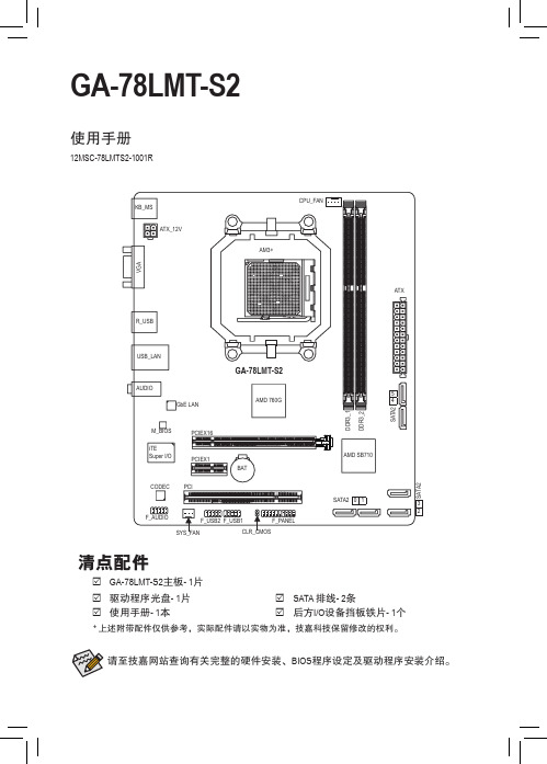
GIGABYTE GA-78LMT-S2 说明书
最后,我们建议您通过认识和使用此产品的节能特点(适用的话),来实践其他环境友善的行动,回收再利用此产品所交付的的内部与外部包装材(包含运输货柜),并且正确地处理或回收再利用所使用的电池。
有你的帮助,我们才能减少生产电器及电子设备所需自然资源的数量,尽可能减少最终产品的垃圾掩埋处置耗用,所以一般通过确保潜在的危害物质不会释放到环境,以及与正确的处理来增进我们的生活品质。
中华人民共和国电子信息产品中有毒有害物质或元素的名称及含量标识格式依照中华人民共和国的有毒有害物质的限制要求(China RoHS)提供以下的表格:版权© 2012年,技嘉科技股份有限公司,版权所有。
本使用手册所提及的商标与名称,均属其合法注册的公司所有。
责任声明本使用手册受著作权保护,所撰写的内容均为技嘉所拥有。
本使用手册所提及的产品规格或相关信息,技嘉保留修改的权利。
本使用手册所提及的产品规格或相关信息有任何修改或变更时,恕不另行通知。
未事先经由技嘉书面允许,不得以任何形式复制、修改、转载、传播或出版本使用手册内容。
产品相关信息,请至网站查询:/MotherboardGA-78LMT-S2Apr. 20, 2012Apr. 20, 2012MotherboardGA-78LMT-S2•技嘉科技股份有限公司地址:新北市231新店区宝强路6号电话:+886 (2) 8912-4000,传真:+886 (2) 8912-4003技术服务专线:0800-079-800 , 02-8665-2646服务时间:星期一~星期五 上午 09:30 ~下午 08:30星期六 上午 09:30 ~下午 05:30技术/非技术问题支持:网址(英文):网址(中文):http://www.gigabyte.tw您也可以至技嘉网站,点选右上角的国别选单,选取您所适用的语言。
技嘉科技全球服务网技嘉主板售后服务及质量保证卡亲爱的技嘉用户,感谢您选用技嘉科技的主板产品,选择技嘉——创新科技,美化生活。
主板报价

技嘉GA-Z68P-DS3 ¥450
技嘉GA-Z68AP-D3 ¥500
技嘉GA-Z68M-D2H ¥400
技嘉GA-Z68XP-UD3R(rev.1.3) ¥750
映泰T5 XE ¥300
映泰TP55 ¥350
翔升凌志P55T ¥180
翔升凌志P55T-S ¥230
映泰H55 HD ¥240
映泰网吧1号H55A+ ¥300
映泰TH55B HD 6.x ¥260
映泰TH55 XE ¥350
intel主芯片组X79 系列:
华硕RAMPAGE IV EXTREME/BF3 ¥2600
华硕SABERTOOTH X79 ¥1750
华硕Rampage IV Formula/BATTLEFIELD 3 ¥2000
华硕P8P67 LE ¥400
华硕SaberTooth P67 ¥650
华硕P8P67 pro ¥800
华硕Maximus IV Extreme ¥2000
技嘉GA-X79-UD3 ¥1150
技嘉G1.Assassin2 ¥2050
映泰TPower X79 ¥980
微星X79A-GD65(8D) ¥1250
华硕P8H67-M PRO ¥480
华硕P8H67-I DELUXE ¥700
华硕P8H67-V ¥400
华硕P8H67-M EVO ¥600
微星PH67S-C43(B3) ¥310
微星H67MA-E45(B3) ¥400
技嘉GA-H67MA-USB3-B3 ¥380
技嘉GA-PH67A-D3-B3 ¥400
华硕P7H55-M ¥350
是德科技 U2781A USB 模块式仪器机箱 快速入门指南说明书

6
Keysight U2781A 快速入門指南
法規標誌
貼有此 CE 標誌表示產品符合所有 相關的「歐盟法規指令」( 如果標 誌載有年份,即表示為該設計的 核准年度 )。
CSA 標誌是「加拿大標準協會」的 註 冊 商 標。CSA 標 誌 含有 “C” 和 “US” 的字樣,表示產品通過美國 和加拿大市場的檢定,符合適用 之美國和加拿大標準。
符合標準聲明
本產品和其他 Keysight 產品的符合標準 聲明可從 Web 進行下載。前往 /go/conformity。 然後,可以按產品編號搜尋,找到最新 的符合標準聲明。
美國政府權利
本軟體係聯邦收購法規 (「FAR」) 2.101 所界定之 「商業電腦軟體」。根據 FAR 12.212 和 27.405-3 以及國防部補充條 款 (「DFARS」) 227.7202,美國政府依 據向公眾提供商業電腦軟體的一般條款 獲得本軟體。同樣,Keysight 根據其標 準商業授權向美國政府客戶提供本軟 體,該 授 權 包 含 在 其 使 用 者 授 權 合 約 (EULA) 中,可於下列位置找到該授權合 約 的副 本:/ find/sweula。EULA 中所述的授權表示 美國政府在使用、修改、散佈或揭露本 軟體方面的專屬授權。除了其他事項以 外,EULA 及其所述的授權不要求或不 允許 Keysight:(1) 提供通常不會向公眾 提供的與商業電腦軟體或商業電腦軟體 文件相關的技術資訊;或者 (2) 讓與或 以其他方式提供的政府權利超過通常向 公眾提供的有關使用、修改、重現、發 佈、執行、顯示或揭露商業電腦軟體或 商業電腦軟體文件方面的權利。EULA 中未涉及的其他政府要求不適用,除非 根據 FAR 和 DFARS 的規定明確要求所 有商業電腦軟體供應商提供這些條款、 權利或授權,並且 EULA 中的其他地方 有專門的書面說明。Keysight 不承擔更 新、修訂或修改本軟體的責任。關於 FAR 2.101 所 界定 之 任何 技 術資 料,根據 FAR 12.211 和 27.404.2 以 及 DFARS 227.7102,在適用於任何技術資料的情 況下,美國政府使用者所獲取的權利, 不得超過依據 FAR 27.401 或 DFAR 227.7103-5 (c) 所界定之「有限權利」。
NEC 8位单片控制器 78KOS KB1+ 说明书

78K0S/KB1+
8 位单片微控制器
PD78F9232 PD78F9234
版次: 印次:
U17446EJ2V0UD00 ( 第一版) 2005 年 4 月 NS CP(K)
NEC 公司 日本印制
2005
[ 备忘 录]
2
用户手册 U17446EJ1V0UD
CMOS 设备注意 事项
开发工具(硬件)文档 (用户手册)
文档名称 IE-78K0S-NS 在线仿真器 IE-78K0S-NS -A 在线仿真器 QB-78K0SKX1MINI 在线仿真器 文档编号 U13549E U15207E U17272E
注意事项 以上列出的相关文档在无任何声明条件下可能会作修改。读者应使用每个文档的最新版本用于设计。
Milano,Italy Tel:02-667541 NEC Electronics Taiwan Ltd. Taipei,Taiwan
Branch
The Netherlands
Tel:02-2719-2377
Eindhoven,TheNetherlands Tel:040-2445845 NEC Electronics Singapore Pte.Led. Novena Square,Singapore
③
半导体的 ESD 防护措施
如果 MOS 设备周围有强电场,将会击穿氧化栅极,从而影响设备的运行。因此必须采取措施,尽可能防 止静电产生,而且一旦有静电,必须立即释放。对于环境必须有适当的控制。如果空气干燥,应当使用 加湿器。建议避免使用绝缘体,因为它们容易产生静电。半导体设备的存放和运输必须在抗静电容器、 抗静电屏蔽袋或导电材料容器中进行。所有的测试和测量工具包括工作台和工作面必须良好接地。操作 员应当佩戴静电消除手套以保证良好接地,不能用手直接接触半导体设备。对于装配有半导体设备的 PW 板也应采取类似的静电防范措施。
华硕主板

数字家庭主板M2NDH-支持AMD®SocketAM2Athlon64FX/Athlo64X2/Athlon64/Sempron -AMDLive!™Ready-强大扩充能力:1xPCI-Ex16、2xPCI-E、3xPCI-华硕WiFi-APSolo-华硕DHRemote™-华硕MP3-In™-华硕Q-Connector-高保真音频中央处理器支持AMD®SocketAM2Athlon64FX/Athlo64X2/Athlon64/Sempron 支持AMDCool'n'Quiet™技术AMD64架构,同时兼容32位和64位计算AMDLive!™Ready芯片组NVIDIAnForce®430MCP前端总线2000/1600MT/s内存双通道内存架构4x240-pinDIMM内存插槽,支持最大容量高达8GB的DDR2800/667/533ECC和non-ECC、un-buffered内存扩充插槽1xPCI-Expressx16插槽2xPCI-Expressx1插槽3xPCI2.2插槽存储装置/RAID-1xUltraDMA133/100/66/33-4xSerialATA3.0Gb/s-NVIDIAMediaShield™RAID通过SerialA TA设备支持RAID0、1、0+1、5和JBOD网络功能NVIDIAnForce®430内建GigabitMAC,支持externalAttansicPHY无线局域网:54MbpsIEEE802.11b/g(华硕WiFi-APSolo)音频功能ADI6声道高保真音频CODEC背板S/PDIF数字音频输出USB高达8个USB2.0/1.1接口M2N-VMDH-AMDSocketAM2-NVIDIAGeForce6100/nForce430-双通道DDR2800/667/533-1xPCIExpressx16+1xPCIExpressx1+2xPCI-双VGA:DVI-D和D-Sub-8声道高保真音频-2x1394a接口中央处理器支持AMD®SocketAM2Athlon64X2/Athlon64FX/Athlon64/Sempro nAMDCool'n'Quiet™技术AMD64架构,兼容32位和64位计算AMDLive!™Ready芯片组NVIDIAGeForce6100/nForce430前端总线2000/1600MT/s 内存双通道内存架构4x240-pinDIMM插槽,支持最大容量为8GB的DDR2800/667/533non-ECC,un-buffered内存显卡集成GeForce6100GPU高清晰视频处理,最高分辨率可达1920x1440(@75Hz)支持RGB显示;UXGA1600x1200(@60Hz)支持DVI-D显示支持双VGA输出:DVI-D和RGB注意:DVI-D不能用来输出RGB信号至CRT。
8-Bit USB Debug Adapter 用户指南说明书

Rev. 0.3 1/15Copyright © 2015 by Silicon Laboratories8-Bit USB Debug AdapterIT EBUG DAPTER SER S UIDE1. IntroductionThe 8-bit USB Debug Adapter (UDA) provides the interface between the PC’s USB port and the Silicon Labs 8-bit target device’s in-system debug/programming circuitry. The 10-pin ribbon cable connects the adapter to the target board and the target device’s debug interface.Figure1.8-Bit USB Debug AdapterVisit /8bit-uda for ordering information.2. Relevant DocumentationApplication notes can be found on the 8-bit MCU Application Notes web page: /appnotes .⏹ AN124: Pin Sharing Techniques for the C2 Interface —Describes in detail the debug interface pinsharing feature for C2 devices, which enables debugging and use of the /RST and GPIO pins shared with C2CK and C2D.⏹ AN117: Using C8051Fxxx On-Chip Interface Utilities DLL —The SiUtil DLL discussed in this document uses the USB Debug Adapter to program the memory space of C2 and JTAG devices.⏹ AN134: Multiple-Device JTAG Configuration in the Silicon Labs IDE —Configuration in the IDE and using the USB Debug Adapter for devices in a JTAG chain.8-Bit USB Debug Adapter3. Pinout SpecificationThe 8-Bit USB Debug Adapter supports both Silicon Laboratories JTAG and C2 debug interfaces, and the adapter is powered from the USB connection to the PC. The UDA is also capable of providing power to the target device or other circuitry via pin 10 of the connector. Table1 shows the pin definitions for the UDA keyed connector. The part number for the matching shrouded and keyed connector for a PCB is 2510-6002UB from 3M.The USB Debug Adapter can automatically change the communication voltage level based on the level detected on pin 7 of the connector. As a result, this pin should be pulled high with a strong pull-up (~1kΩ) for noise immunity purposes and not pulled down to ground.Notes:•The USB Debug Adapter requires a target system clock of 32kHz or greater.•With the default settings, the USB Debug Adapter can supply up to 100 mA to a target system.Table 1. USB Debug Adapter Debug Connector Pin DescriptionsPin #Description Details1Not Connected2GND (Ground)3GND (Ground)4TCK / C2D JTAG TCK or C2 Data5TMS / C2CK pin share JTAG TMS or C2 Clock pin sharing6TDO / C2D pin share JTAG TDO or C2 Data pin sharing7TDI / C2CK JTAG TDI or C2 Clock signalThis pin is used by the UDA to sense and setthe logic voltage level. This pin should neverhave a pull-down to ground.8Not Connected9GND (Ground)10USB Power 5 V power from the UDA8-Bit USB Debug Adapter4. Minimum C2 Programming ConnectionsThe minimum required programming connections for the C2 interface are C2D (pin 4), C2CK (pin 7), and ground (pins 2, 3, or 9).5. Hardware Setup using a USB Debug AdapterConnect a target board to a PC running the Silicon Laboratories IDE via the USB Debug Adapter as shown in Figure 3.1. Connect the USB Debug Adapter’s 10-pin ribbon cable to the JTAG or Debug connector on the target board.2. Connect one end of a standard USB cable to the USB connector on the USB Debug Adapter.3. Connect the other end of the USB cable to a USB Port on the PC.4. Power the target board.Notes:•Use the Reset button in the IDE to reset the target when connected using a USB Debug Adapter.•Remove power from the target board and the USB Debug Adapter before connecting or disconnecting the ribbon cable from the target board. Connecting or disconnecting the cable when the devices have power can damage the device and/or the USB Debug Adapter.Figure 3.Hardware Setup using a USB Debug Adapter6. USB DriversThe USB Debug Adapter uses the Human Interface Device (HID) USB interface to communicate with the PC.Since most operating systems have this driver automatically built in, no drivers need to be installed to use the UDA.1238-Bit USB Debug Adapter7. Software Setup using a USB Debug AdapterThe Silicon Laboratories Integrated Development Environment (IDE) along with other software tools are provided for device development and debugging. The IDE is available for download from the Silicon Laboratories website (/mcudownloads ) and is also available on microcontroller development kit CD-ROMs.7.1. Configuring the USB Debug Adapter in the Silicon Labs IDEOnce the IDE has been installed and the hardware has been connected as shown in Section 5, follow the steps below to built a project, connect and download to a target board using the USB Debug Adapter.1. Select Project →Open Project... to open a previously saved project.2. Before connecting to the target device, several connection options may need to be set. Open the Connection Options window (shown in Figure 4) by selecting Options →Connection Options... in the IDE menu.3. Select USB Debug Adapter in the Serial Adapter section.4. If more than one adapter is connected, choose the appropriate serial number from the drop-down list.5. Check the Power target after disconnect option if the target board is currently being powered by the USB Debug Adapter. The board will remain powered after a software disconnect by the IDE.6. Next, the correct Debug Interface must be selected. Check the Debug Interface corresponding to the Silicon Laboratories device on the target board.7. Once all the selections are made, click the OK button to close the window.8. Click the Connect button in the toolbar or select Debug →Connect from the menu to connect to thedevice. 9. Download the project to the target by clicking the Download Code button in the toolbar.10. Save the project when finished with the debug sessionto preserve the current target build configuration, editor settings and the location of all open debug views. To save the project, select Project →Save Project As... from the menu. Create a new name for the project and click on Save .Figure 4.Connection Options8-Bit USB Debug Adapter 8. SchematicsDisclaimerSilicon Laboratories intends to provide customers with the latest, accurate, and in-depth documentation of all peripherals and modules available for system and software implementers using or intending to use the Silicon Laboratories products. Characterization data, available modules and peripherals, memory sizes and memory addresses refer to each specific device, and "Typical" parameters provided can and do vary in different applications. Application examples described herein are for illustrative purposes only. Silicon Laboratories reserves the right to make changes without further notice and limitation to product information, specifications, and descriptions herein, and does not give warranties as to the accuracy or completeness of the included information. Silicon Laboratories shall have no liability for the consequences of use of the information supplied herein. This document does not imply or express copyright licenses granted hereunder to design or fabricate any integrated circuits. The products must not be used within any Life Support System without the specific written consent of Silicon Laboratories. A "Life Support System" is any product or system intended to support or sustain life and/or health, which, if it fails, can be reasonably expected to result in significant personal injury or death. Silicon Laboratories products are generally not intended for military applications. Silicon Laboratories products shall under no circumstances be used in weapons of mass destruction including (but not limited to) nuclear, biological or chemical weapons, or missiles capable of delivering such weapons.Trademark InformationSilicon Laboratories Inc., Silicon Laboratories, Silicon Labs, SiLabs and the Silicon Labs logo, CMEMS®, EFM, EFM32, EFR, Energy Micro, Energy Micro logo and combinations thereof, "the world’s most energy friendly microcontrollers", Ember®, EZLink®, EZMac®, EZRadio®, EZRadioPRO®, DSPLL®, ISOmodem ®, Precision32®, ProSLIC®, SiPHY®, USBXpress® and others are trademarks or registered trademarks of Silicon Laboratories Inc. ARM, CORTEX, Cortex-M3 and THUMB are trademarks or registered trademarks of ARM Holdings. Keil is a registered trademark of ARM Limited. All other products or brand names mentioned herein are trademarks of their respective holders.Silicon Laboratories Inc.400 West Cesar Chavez Austin, TX 78701USAIoT Portfolio /IoTSW/HW/simplicityQuality/qualitySupport and Community。
联想品牌机家用家悦等主板改线、主板跳线大全
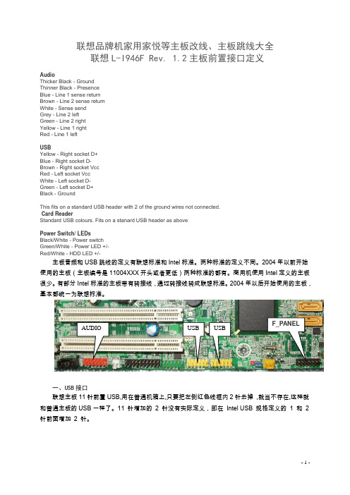
联想品牌机家用家悦等主板改线、主板跳线大全 联想L-I946F Rev. 1.2主板前置接口定义AudioThicker Black - Ground Thinner Black - Presence Blue - Line 1 sense return Brown - Line 2 sense return White - Sense send Grey - Line 2 left Green - Line 2 right Yellow - Line 1 right Red - Line 1 left USBYellow - Right socket D+ Blue - Right socket D- Brown - Right socket Vcc Red - Left socket Vcc White - Left socket D- Green - Left socket D+ Black - GroundThis fits on a standard USB header with 2 of the ground wires not connected. Card ReaderStandard USB colours. Fits on a stanard USB header as abovePower Switch/ LEDsBlack/White - Power switch Green/White - Power LED +/- Red/White - HDD LED +/-主板音频和USB 跳线的定义有联想标准和Intel 标准。
两种标准的定义不同。
2004年以前开始使用的主板(主板编号是11004XXX 开头或者更低)两种标准的都有。
商用机使用Intel 定义的主板很少。
有部分Intel 标准的主板带有转接线,通过转接线转成联想标准。
2004年以后开始使用的主板,基本都统一为联想标准。
昂达785G芯片组主板说明书

ONDAA78GLD3/A785GD3/A88GC用户手册Rev:2.0Date:2010.04给用户的说明本产品的所有部分,包括配件与软件等,其所有权都归本公司所有,未经本公司许可,不得任意地仿制、拷贝、摘抄或转译。
本用户手册没有任何形式的担保、立场表达或其它暗示。
若有任何因本用户手册或其所提到之产品的所有资讯,所引起直接或间接的信息流失或事业终止,本公司及其所属员工恕不为其担负任何责任。
除此之外,本用户手册所提到之产品规格及资讯仅供参考,内容亦会随时更新,恕不另行通知。
本用户手册的所有部分,包括硬件及软件,若有任何错误,本公司没有义务为其担负任何责任。
本手册所谈论到的产品名称仅做识别之用,而这些名称可能是属于其他公司的注册商标或是版权,在此声明如下:IBM,VGA和PS/2属于International Business Machines的注册商标。
Intel, Pentium, Pentium Ⅱ, Celeron, Pentium III, Pentium 4属于Intel的注册商标。
Microsoft, MS-DOS, Windows 95/98/NT, Windows2000/XP等属于Microsoft的注册商标。
PC-Cillin和ChipAway Virus属于Trend Micro Inc的注册商标。
AMI属于美国Megatrends Inc的注册商标。
Award属于Award的注册商标。
MediaRing Talk属于MediaRing的注册商标。
3Deep属于E-Color的注册商标。
本手册中出现的其他商标均已注册。
目录第一章包装说明 (3)第二章综述 (4)第三章主板位图 (6)第四章安装与设置 (7)第五章BIOS的设置 (13)5.1 进入BIOS 主界面 (13)5.2 控制键位 (13)5.3 主题帮助 (14)5.4 BIOS 主界面 (14)5.5 高级BIOS功能设置 (16)5.6 启动设置 (22)5.7 安全设置 (24)5.8 电源管理设置 (25)5.9 OverDrive设置 (28)5.10离开BIOS设置程序 (31)第六章主板驱动安装 (33)第一章包装说明请确认您所购买的主板包装是否完整,如果有包装损坏或是有任何配件短缺的情形,请尽快与您的经销商联系。
NEC 78k
Deliver to:NEC Electronics Hong Kong LimitedDeliver from:Beijing NEC IC Design Corp, LtdNEC Tools 78Kx系列用户手册VERSION 1.0Date Published Jun, 2004前言目的本手册的目的是向用户讲解NEC开发工具包——NEC Tools的基本概念和操作。
通过本手册的指导,用户可以实际使用NEC Tools中的PM plus和SM78K0 plus、SM78K0s plus工具,分别针对78K0和78K0s系列芯片进行编程开发活动。
预备知识本手册面向的读者是准备开发基于78K0和78K0s芯片的软件的初学者。
读者需要具备一定的C、汇编和微处理器(MCU)的基础知识。
章节本手册分为以下几个章节:Ÿ安装Ÿ范例Ÿ简介Ÿ编译Ÿ调试术语78Kx: 78K0和78K0s在本手册中统称为78Kx。
在NEC开发工具中,78K0系列CPU和78K0s系列CPU各有一套独立的开发工具。
参考文档本手册参考的文档都是NEC正式发布的文档,可以在以下网址索引到:http:///en/search/index.html#document参考文档名称编号CC78K0 UM U16613ECC78K0s UM U16654ERA78K0 UM U16629ERA78K0s UM U16656ESM78K V2.52 UM U16768EPMplus E5.10 UM U16569E1目录前言 (1)目录 (2)第 1 章安装开发工具 (4)1.1安装ra78Kx/PM plus (4)1.1.1安装包内容 (4)1.1.2安装步骤 (4)1.2安装cc78Kx (7)1.2.1安装包内容 (7)1.2.2安装步骤 (8)1.3安装SM78Kx PLUS (10)1.3.1安装包内容 (10)1.3.2安装步骤 (11)1.4安装设备文件 (14)1.4.1简介 (14)1.4.2安装步骤 (14)第 2 章应用范例 (17)2.1环境 (17)2.2编译 (17)2.3运行 (18)2.3.1启动SM78K0s plus (18)2.3.2打开工程 (18)2.3.3运行和观测 (20)第 3 章NEC Tools开发环境简介 (22)3.1概述 (22)3.2集成编译环境 PM plus (22)3.3仿真调试环境 SM plus (22)3.4C编译器 cc78Kx (22)3.5汇编编译器 ra78Kx (23)3.6链接器 lk78Kx (23)3.7目标文件转化器 oc78Kx (24)3.8库生成器 lb78Kx (24)第 4 章集成开发环境 (26)4.1使用PM plus编译 (26)4.1.1启动PM plus (26)4.1.2工程术语 (26)4.1.3创建Workspace (27)4.1.4读取Workspace (30)4.1.5Build工程(Project) (31)4.2选项设置 (32)第 5 章仿真调试环境 (34)25.1基本步骤 (34)5.1.1启动 (34)5.1.2加载目标文件 (35)5.1.3加载源文件 (36)5.1.4加载工程文件 (37)5.1.5在源文件中设置断点 (38)5.1.6执行程序 (39)5.1.7单步执行 (39)5.1.8停止执行 (40)5.1.9重启 (41)5.1.10观察和修改变量值 (42)5.1.11观察和修改寄存器值 (43)5.1.12观察汇编代码 (45)5.1.13设置汇编断点 (46)5.1.14修改汇编代码 (47)5.1.15退出SM78Kx plus (47)5.2高级调试功能 (47)5.2.1Event(事件) (47)5.2.2断点 (50)5.2.3Timer(计时) (51)5.2.4Trace(追踪) (53)5.2.5Timing Chart(时序图) (54)5.2.6Signal Data Editor(信号编辑器) (55)5.2.7I/O Panel(I/O面板) (58)5.2.8Standard I/O (61)5.2.9Serial GUI (62)3第 1 章 安装开发工具4第 1 章 安装开发工具本章将介绍如何安装NEC 工具包ra78Kx/PM plus 、cc78Kx 和SM78Kx plus 。
GA-78LMT-S2_R1.21

14 ATI SB710 ACPI/USB/GPIO/AUDIO
15 ATI SB710 SATA/IDE/HWM/SPI
B
16 ATI SB710 POWER & GND
17 PCI EXPRESS x16 ,x1
18 PCI SLOT
19 LAN AR8151/8152
20 ALC887-VD2
07 CPU POWER & GND
C
08 DDRIII CHANNEL A0, B0
09 RS780 HT-LINK I/F
10 RS780 SYSTEM I/F,STRAP,DVI
11 RS780 POWER & GND
12 IDT 9LPRS485C
13 ATI SB710 PCIE/PCI/CPU/LPC/CLK
D
Clock
D
Generator
AM3 SOCKET
DDRIII 1066 / 1333
UNBUFFERED
RT880T-792 12
4,5,6,7
DDRIII DIMM2 8
HyperTransport LINK
16xห้องสมุดไป่ตู้6
DDRIII FIRST LOGICAL DIMM
VGA
RGB
CON
23
PCIE SLOT
2012.04.13 1.0 Gerber out
1. change PCB Ver 1.0 2. Add "RB" 文文文
2012.07.02 1.1 Gerber out
Change MOS_OT pin. Add COM port pin-header
三星i8700刷机教程,三星i8700,Omnia7刷机教程
三星i8700刷机教程,三星i8700,Omnia7刷机教程制式项器 E-mail 闪光灯制式重力多媒体系统光线直板加速材质罗盘色彩数 GPS分辨率 500 万特色传感基本参数型号手机类型上市时间手机制式手机频段系统手机外形主屏尺寸主屏材质主屏色彩主屏参数触摸屏 CPU CPU 内存容量标准配置电池容量尺寸重量I8700 智能手机,音乐手机,拍照手机,3G 手机xx 年 GSM,WCDMA(联通 3G) GSM 850/900/1800/1900,WCDMA 2100MHz Windows Phone 7 直板 4.0 英寸 AMOLED 1600 万色 480×800 像素(WVGA) 电容屏,多点触摸高通 Qualm QSD8250 1GHz 576MBRAM,512MB ROM,8GB NAND 锂电池,说明书,充电器 1500mAh 122×64.3×11mm 138g基本功能信息功能 E-mail 收发游戏办公功能主要功能SMS 短信支持 E-mail,支持 SMTP,POP3,IMAP4 等邮件协议内置游戏支持 TXT,Office(word,excel,ppt) 内置天线,时钟,内置震动,情景模式,免提通话,待机图片,来电图片识别,制式项器 E-mail 闪光灯制式重力多媒体系统光线直板加速材质罗盘色彩数 GPS分辨率 500 万特色传感基本参数质保政策质保时间全国联保,享受三包服务主机 1 年,电池 6 个月,充电器 1 年,有线耳机 3 个月自购机日起(以购机发票为准),如因质量问题或故障,凭厂商维修中心详细内容或特约维修点的质量检测证明,享受 7 日内退货,15 日内换货,15 日以上在质保期内享受保修等三包服务!如今三星i917(Focus)和i8700(Omnia 7)也已经可以刷DFT 系列ROM了,Zune123之前也曾经介绍过三星i917 i8700刷DFT系列ROM所做的准备工作(刷DFT MAGLDR 2.0),这次带来的则是三星i917 i8700刷DFT ROM教程。
华硕 M5A78L USB3 主板用户手册

之損害。 B. 自行拆裝、修理、或將產品送至非華碩認証之維修點進行檢測維修。 C. 用戶擅自或請第三人修改、修復、變更規格及安裝、添加、擴充非本公司原廠銷售、授權
ii
三年質保
全國聯保
請用剪刀沿虛線剪下
華碩產品質量保證卡
尊敬的華碩產品用戶:
首先非常感謝您選用華碩公司產品,讓我們有機會向您提供優質的服務。為了使我們的服務讓您 更滿意,在購買後請您認真閱讀此說明並妥善保存此質量保證卡。
保修說明注意事項:
一、 請將此質量保證卡下方的用戶資料填寫完整,並由最終直接經銷商加蓋印章,如果沒有加蓋印 章,請找原購買處補蓋以保障您的權益。請務必保留購買發票或複印件,否則華碩公司將以產 品的出廠日期為參照進行保修。
Motherboard
M5A78L/USB3
用戶手冊
C6588 第一版(V1) 2011 年 4 月發行
版權所有‧不得翻印 © 2011 華碩電腦 本產品的所有部分,包括配件與軟件等,其相關知識產權等歸華碩電腦公司(以下簡稱華
碩)或授權華碩使用的相關主體所有,未經權利主體許可,不得任意地仿製、拷貝、摘抄或轉 譯。本用戶手冊沒有任何型式的擔保、立場表達或其它暗示。若有任何因本用戶手冊或其所提到 之產品信息,所引起直接或間接的數據流失、利益損失或事業終止,華碩及其所屬員工恕不為其 擔負任何責任。除此之外,本用戶手冊所提到的產品規格及信息只做參考,內容亦會隨時更新, 恕不另行通知。
關於這本用戶手冊...................................................................................................................... ix 用戶手冊的編排方式...................................................................................................... ix 提示符號.............................................................................................................................. ix 跳線帽及圖示說明........................................................................................................... ix 哪裡可以找到更多的產品信息.................................................................................... x
海信新型USB升级工具使用指南
18 / 24
图 3.32
图 3.37 X.N 如果之前没有烧过主程序,打开 SecureCRT 显示为图 3.37,如果烧入过主程 .IFI 序,那么会看到一直有打印信息,这时需要重启一下,两种方式重启:一、硬重 WW 启,直接用电视开关进行重启,在按开关的同时,将光标的焦点放在 SecureCRT W 的界面上,并按住回车(Enter)键,电视启动后会停在图 3.37 的状态,这时,
W
W
W
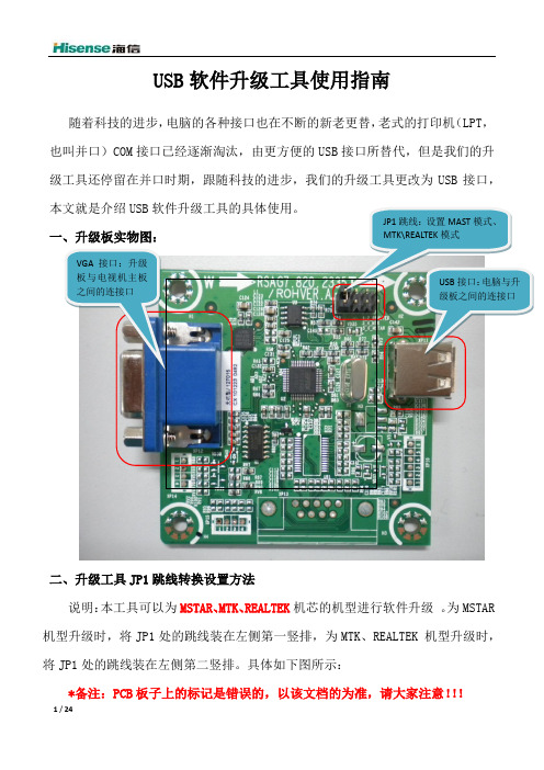
该 JP1 所处状态是升级 MTK\REALTEK 方案的
该升级工具使用了 2 个主要芯片,其中 CP2102 是 USB 转 RS232(TTL 电平,
适用 MTK、REALTEK 方案)的作用。FT2232D 是 USB 转 Mstar USB Serial Port(只
适用 Mstar 方案)。每种芯片对应都有相应的驱动程序具体见附件驱动程序包。
19 / 24
(3)这时按 F3,显示“<<mstar>># set serverip 172.16.4.177; set ipaddr 172.16.4.178; save”,(注:这里的显示的 IP 是上面以我的为例配置的,自 己用时需要按上面说的配置),然后点击回车开始配置 ip,配置完成后显示 “<<mstar>># ”; (4)这时按下 F4,显示“<<mstar>># mstar set_partition”,点击回车键 开始对 flash 进行分区,分区完成后显示“<<mstar>># ”; (5)按下 F5,显示“<<mstar>># mstar”,点击回车键开始烧写主程序,这 时就不需要其他操作,主程序烧写需要 1~2 分钟,烧写完成后电视会自动启 动,启动后无异常就烧写完成了。
B78硬件接口手册
上海亮衡信息科技有限公司
日期
版本
2015-02-13 1.0.0 2015-02-25 1.0.1
文档更新记录
变更内容
初始版 修订
B78 硬件接口手册
备注
上海亮衡信息科技有限公司
B78 硬件接口手册
目录
目录..................................................................................................................................................... 3 1 介绍.............................................................................................................................................4
B78 模块的 LTE 部分完全满足 3GPP R9 规范对 UE 必选项的要求。
B78 模块支持的工作频段见下表:
制式 GSM Band2 GSM Band3 GSM Band8 TD-SCDMA Band34 TD-SCDMA Band39
FDD LTE B1 FDD LTE B3 FDD LTE B8 TD-LTE B38 TD-LTE B39 TD-LTE B40 TD-LTE B41
表 1- 1 B78 模块支持的工作频段 上行
1850-1910 MHZ 1710-1785 MHz 880-915 MHz 2010-2025MHz 1880-1920 MHz 1920-1980 MHz 1710-1785 MHz 880-915 MHz 2570-2620 MHz 1880-1920 MHz 2300-2400 MHz 2496-2690 MHz
华硕M3A78主板参数

华硕M3A78主板参数- 支持高达140W的AMD® AM2/AM2+ CPU- 使用时间长达5000小时的VRM固态电容一、中央处理器AMD Socket AM2+/AM2支持AMD Phenom™ FX/Phenom/Athlon™/Sempron™处理器支持高达140W的CPUAMD Live!™ Ready支持AMD Cool'n'Quiet™技术二、芯片组AMD 770/SB700三、前端总线高达5200 MT/s的HyperTransport™ 3.0总线,支持AM2+CPU 2000/1600 MT/s 总线,支持AM2 CPU四、内存4 x DIMM内存插槽,最大容量8GB,支持DDR2 1066/800/667/533、ECC、non-ECC内存双通道内存架构*由于AMD CPU的限制,仅在使用AM2+ CPU时支持DDR2 1066,而且每个通道只能使用一根内存条。
**请查阅华硕网站或用户手册了解内存QVL(Qualify Vendor List)***当您安装4GB以上内存时,Windows® 32位操作系统可能仅识别为3GB以下。
因此,推荐使用3GB以下的内存。
五、扩充插槽1 x PCIe x16插槽2 x PCIe x1插槽3 x PCI 2.2插槽支持PCIe 2.0/1.0架构六、存储功能南桥- 1 x UltraDMA 133/100接口- 6 x SATA 3 Gb/s接口,支持RAID 0、1、0+1、JBOD七、网络功能千兆网卡八、音频功能VT1708B 8声道高保真音频编码解码器支持Multi-streaming技术和Jack-detect功能S/PDIF数字音频输出接口,位于背板I/O九、USB12 x USB 2.0接口(6个位于主板上,6个位于背板)十、超频功能SFS(无段频率调节),FSB频率从200MHz调节至300MHz,以1MHz幅度微调以0.025V的幅度调节CPU的核心电压华硕C.P.R.(CPU参数恢复)十一、背板I/O 接口1 x PS/2键盘接口1 x S/PDIF数字音频输出接口(光纤)1 x LPT接口1 x COM接口1 x RJ45 LAN插孔6 x USB 2.0/1.1接口8声道音频I/O插孔十二、内建I/O 接口3 x USB接针,支持6个USB接口1 x CPU风扇接口1 x 机箱风扇接口1 x 电源风扇接口前面板音频接口1 x S/PDIF数字音频输出接口机箱开启检测接口CD音源输入接口24-pin ATX电源接口4-pin ATX 12V电源接口系统面板接口十三、BIOS8Mb Flash ROM,AMI BIOS,PnP,DMI2.0,WfM2.0,SM BIOS 2.5,ACPI 2.0a 十四、附件1 x UltraDMA 133/100数据线1 x 软驱数据线1 x SATA数据线1 x SATA电源线1 x I/O Shield挡板1 x用户手册十五、随机光盘驱动程序华硕PC Probe II系统诊断家Express Gate华硕LiveUpdate在线更新程序防毒软件(OEM版本)十六、产品规格ATX规格12英寸x 9.6英寸(30.5厘米x 24.4厘米)。
MT7813规格书-中文 _Rev1.20(1)

描述MT7813是一款工作于零电流导通,峰值电流关断的临界导通模式(CRM ,Critical Conduction Mode )高精度LED 恒流控制芯片,主要应用于非隔离降压型LED 电源系统。
临界导通模式确保了MT7813可以控制功率开关在电感电流为零时刻开启,减小了功率管的开关损耗,确保了系统具有95%以上的峰值效率。
电感电流谷值为零的临界导通模式结合经过输入母线电压补偿后的峰值电感电流,确保了输出LED 电流的高精度,并且具有良好的线性调整率和负载调整率。
对电感量变化不敏感,可以使用工字电感,。
芯片内置高压功率MOS 管,外围电路简单,系统成本低。
MT7813工作电压宽,适合全范围交流输入电压或是10V —400V 直流电压输入。
MT7813同时实现了各种保护功能,包括逐周期过流保护(OCP )、LED 短路保护(SCP )、LED 开路保护(OVP )和过热保护(OTP )等,以确保系统可靠地工作。
∙ 临界导通模式,对电感不敏感 ∙ 最高95%以上的峰值效率 ∙ 高精度LED 恒流电流 ∙ 逐周期峰值电流控制 ∙ LED 短路保护 ∙ LED 开路保护 ∙ 前沿消隐控制 ∙ 欠压锁定保护(UVLO) ∙ 过温保护 ∙SOP8 / DIP8封装应用∙ LED 球泡灯,日光灯,信号灯,景观灯等 ∙ LED 舞台灯,蜡烛灯,玉米灯等 ∙其他LED 驱动应用及通用恒流源典型应用电路极限参数推荐工作条件管脚排列图管脚描述电气参数原理框图 SWCSVOVP GNDDRAIN功能描述MT7813是一款内置高压功率管的恒流驱动的芯片,适用于LED 照明驱动。
芯片工作于电感电流临界导通模式,控制功率开关在电感电流为零时刻开启,减小了功率管的开关损耗,提高了效率。
采用MT7813芯片的驱动电路恒流精度高,外围元器件少,成本低。
启动过程上电时,VCC 通过一个连接到输入母线的启动电阻充电。
当VCC 达到12V 时,控制逻辑就开始工作,内部开关开始开关动作。
