超声波探头-UTIIIWord版
UT-3资料
C
1
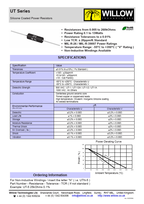
Maximum Working Voltage
MIL-R-26 / MIL-R-39007 Style
UT-1 UT-1/2A UT-1/23 UT-1A UT-2 UT-2A UT-2B UT-2C UT-2E UT-3 UT-5 UT-5A UT-6 UT-7A3 UT-7B UT-7C UT-10
8.5 20 29 52 60 130 140 140 140 210 360 390 504 650 590 620 850
RW-78 RWR-78 RW-67 RW-74 RWR-74 RW-69 RW-79 RWR-79 RW-70
Lead Diameter: 18 AWG = 0.040” / 20 AWG = 0.032” / 22 AWG = 0.025” / 24 AWG = 0.020” / 25 AWG = 0.018” Where more than one lead is listed / the top value is Standard 2 For non-inductive windings / divide maximum resistance by 2 3 This part does not meet the RoHS directive - call factory for details
0.1 0.4 0.75 1.0 1.5 2.5 3.0 3.0 3.0 4.0 5.0 5.0 5.0 7.0 7.0 7.0 10
500 2.5k 7.5k 10k 12.5k 22k 22k 40k 30k 45k 91k 65k 95k 150k 100k 154k 260k
0.150 [3.8] 0.250 [6.4] 0.330 [8.4] 0.406 [10.3] 0.350 [8.9] 0.500 [12.7] 0.560 [14.2] 0.500 [12.7] 0.500 [12.7] 0.625 [15.9] 0.875 [22.2] 0.970 [24.6] 1.000 [25.4] 1.375 [35.0] 1.400 [35.6] 1.220 [31.0] 1.780 [45.2]
III-UT专业试题

UT-III SSPECIFIC EXAMINATION FOR UT-ⅢFOR ASME CODE PRODUCTSASME超声波Ⅲ级检测人员专业考试试题EXAMINEE: DATE: SCORE:应试人:日期:得分:EXAMINER: DA TE:考评人:日期:In the following selecting questions, choose the letter representing the right answer into the brackets (5%each, total 100%)对下列选择题,选择代表正确答案的字母填入括号内1. According to the requirements of the amplitude control of the ultrasonic instrument, if an indication is set at 80% of full screen and its limit is 16~24% of full screen,then the variation of the corresponding sound pressure is()按超声波辐度控制要求,若回波调为80%满屏高,其范围为满屏16~24%,则相应的声压变化为:A. -7.9 ~ -4.4dBB. +4 ~ +7.6dBC. -14 ~ -10.5dBD. +10 ~+13dB2. When the examination equipment shall be checked and calibrated by the use of the calibration standard?()A. At the beginning and end of each examinationB. When examination personnel are changedC. At any time that malfunctioning is suspectedD. All of the above探伤仪何时需用校正试样校验?()A. 每次检测开始和终了B. 检测人员更换时C. 怀疑仪器有故障时D. 以上都是3. The rate of probe movement for examination of welds shall not exceed(), and each pass of the probe shall overlap a minimum of()of the transducer width.焊缝检验时探头移动速度不得大于(),探头每次移动时应保证至少重叠()探头宽度A. 200mm/sB. 6in./sC. 10%D. 20%4. According to T-542, for the ultrasonic examination of welds, the exam-starting level is ( ), the indication-evaluating level is ( ) and the flaw-measuring levelis( )按T-542,焊缝UT的起始灵敏度为(),评定灵敏度为(),定量灵敏度为()。
UT-III级 4730标准超声检测工艺要素总结

基准灵敏度 与工件等厚部位的第一次底波满 屏的50%+10dB(板厚较薄需以 F2或B2评定时,定用F2调灵敏 度)
扫查灵敏度
检测面
扫查方式
耦合曲面补偿
缺陷记录
缺陷测量
双直:隔声层垂直移动方向,F 降至基准 1、F1≥50% 灵敏度条件下25%或F1/B1=50%的严重者 2、B1<100%且F1/B1≥ 。 50% 单直:F1降至基准灵敏度条件下25%或 3、B1<50% F1/B1=50%的严重者。 4、F2定灵敏度时用F2、 B1<50% :B1=50% B2记录 上述探头中心为边界,探头移动距离为 指示长度
探头 6~20mm (大于20mm 双直 5M Fs≥150mm 2(性能 用双直需双 复合附录A) 方协议) 纵直 >20~40 CBI
试块
6~250mm碳钢、低 合金钢。、镍板、A 板、双相不锈钢板可 参考
>40~250
P69
横斜 ≤50mm (对缺 陷有疑 问或技 术协议 >50~150 规定) P114 >150~250
高于基准灵敏度判为不 合格,但判废要求按相 关技术文件规定
高于基准灵敏度判为不 合格,合格级别合同双 方商定
板材、板材
未作规定,直 接接触法或水 浸法,直接接 触法可适当补 偿
1、F1≥40% 2、F1<40%且F1/B1≥ 100% 3、B1<5%
双直:隔声层垂直移动方向,F 降至基准 灵敏度条件下20%或F1/B1=100%的严重 者。 单直:F1降至基准灵敏度条件下20%或 F1/B1=50%的严重者。 B1<5% :B1=40% 上述探头中心为边界,探头移动距离为 指示长度
作业指引——超声波检测(UT)
文件名称 超声波检测(UT)作业指引 发布时间超声波检测(UT)作业指引编制人: 日期:审核人: 日期:批准人: 日期:修订记录日期修订状态修改内容修改人审核人批准人文件名称 超声波检测(UT)作业指引 发布时间1.质量控制流程图文件名称 超声波检测(UT)作业指引 发布时间2.检测人员超声波检测人员必须持有中国船级社(CCS)颁发的资格证书,并在有效期范围内;签发报告、资料审核人员,必须持有国家技术监督局颁发的超声波探伤Ⅱ级或Ⅲ级资格证书,并在有效期内。
3.探伤仪、探头和系统性能3.1.探伤仪:采用A型脉冲反射式超声波探伤仪,其工作频率范围为1~5MHz,仪器至少在荧光屏满刻度的80%范围内呈线性显示。
探伤仪应具有80dB以上的连续可调衰减器,步进级每档不大于2dB,其精度为任意相邻12dB误差在±1dB以内,最大累计误差不超过1dB。
水平线性误差不大于1%,垂直线性误差不大于5%,其余指标应符合ZBY230的规定。
3.2.探头:3.2.1.本工程超声波检测使用的探头有单直探头、单斜探头等,具体划分应符合ZBY344的规定。
3.2.2.晶片有效面积一般不应超过50mm2,且任一边长不应大于25mm。
3.2.3.单斜探头声束轴线水平偏离角不应大于2°,主声束垂直方向不应有明显的双峰。
3.3.超声探伤仪和探头的系统性能:3.3.1.在达到所探工件的最大检测声程时,其有效灵敏度与量应大于或等于10dB。
3.3.2.仪器和探头的组合频率与工称误差不得大于±10%。
3.3.3.仪器和直探头组合的始脉冲宽度:对于频率为5MHz的探头,其占宽不得大于10mm;对于频率为2.5MHz的探头,其占宽不得大于15mm。
3.3.4.直探头的远场分辨力应大于或等于30dB,斜探头的远场分辨力应大于或等于6dB。
3.3.5.仪器和探头的系统性能应按ZBJ04001和ZBJ231的规定进行测试。
3UT--超声检测通用工艺规程-83
超声检测通用工艺规程1.目的为了保证本公司检测工作质量,提供准确可靠的检测数据,特制订本通用工艺规程,本规程对超声检测各环节质量控制要求做出了规定。
2.适用范围2.1 本规程适用于金属材料制承压设备用原材料或者零部件和焊接接头的超声检测,也适用于金属材料制在用承压设备的超声检测。
2.2本规程规定了承压设备厚度的超声波测量方法。
3.编制依据下列凡是注日期的引用文件,仅注日期的版本适用于本文件。
凡是不注日期的引用文件,其最新版本适用于本文件。
3.1 GB/T11345《焊缝无损检测超声波检测技术、检测等级和评定》3.2 GB/T11259《无损检测超声检测用钢参考试块的制作与检验方法》3.3 GB/T27664.1《无损检测超声检测设备的性能与检验第1部分:仪器》3.4 GB/T27664.2《无损检测超声检测设备的性能与检验第2部分:探头》3.5 JB/T8428 《无损检测超声检测用试块》3.6 JB/T9214 《无损检测 A型脉冲反射式超声检测系统工作性能测试方法》3.7 JB/T10061《A型脉冲反射式超声波探伤仪通用技术条件》3.8 JB/T10062 《超声探伤用探头性能测试方法》3.9 NB/T47013.1《承压设备无损检测第1部分:通用部分》3.10 NB/T47013.3《承压设备无损检测第3部分:超声检测》4.职责4.1 检测责任师职责4.1.1负责协助技术负责人对检测过程质量进行控制。
负责编制新的检测项目方案或计划,参与组织实施。
4.1.2负责收集查询检测所需的标准和技术资料。
确定检测方法并负责编制检测作业指导书。
负责确保无损检测所使用的受控文件有效并能满足检测工作的需要。
4.1.3追踪无损检测新技术及发展动态,向无损检测技术负责人反映现有人员技术及仪器设备是否满足检测要求和发展需要,并提出建议和计划。
4.1.4负责编制《金属检验专业施工组织设计》、专业检测方案或工艺卡。
超声波检测讲义UT
超声波检测讲义(UT)超声波探伤是利用超声波在物质中的传播、反射和衰减等物理特性来发现缺陷的一种探伤方法。
与射线探伤相比,超声波探伤具有灵敏度高、探测速度快、成本低、操作方便、探测厚度大、对人体和环境无害,特别对裂纹、未熔合等危险性缺陷探伤灵敏度高等优点。
但也存在缺陷评定不直观、定性定量与操作者的水平和经验有关、存档困难等缺点。
在探伤中,常与射线探伤配合使用,提高探伤结果的可靠性。
超声波检测主要用于探测试件的内部缺陷。
1、超声波:频率大于20KH Z的声波。
它是一种机械波。
探伤中常用的超声波频率为0.5~10MHz,其中2~2.5MHz被推荐为焊缝探伤的公称频率。
机械振动:物体沿着直线或曲线在某一平衡位置附近作往复周期性的运动,称为机械振动。
振幅A、周期T、频率f。
波动:振动的传播过程称为波动。
C=λ*f2、波的类型:(1)纵波L:振动方向与传播方向一致。
气、液、固体均可传播纵波。
(2)横波S:振动方向与传播方向垂直的波。
只能在固体介质中传播。
(3)表面波R:沿介质表面传播的波。
只能在固体表面传播。
(4)板波:在板厚与波长相当的薄板中传播的波。
只能在固体介质中传播。
3、超声波的传播速度(固体介质中)(1) E:弹性横量,ρ:密度,σ:泊松比,不同介质E、ρ不一样,波速也不一样。
(2)在同一介质中,纵波、横波和表面波的声速各不相同 C L>C S>C R钢:C L=5900m/s, C S=3230m/s,C R=3007m/s4、波的迭加、干涉、衍射⑴波的迭加原理当几列波在同一介质中传播时,如果在空间某处相遇,则相遇处质点的振动是各列波引起振动的合成,在任意时刻该质点的位移是各列波引起位移的矢量和。
几列波相遇后仍保持自己原有的频率、波长、振动方向等特性并按原来的传播方向继续前进,好象在各自的途中没有遇到其它波一样,这就是波的迭加原理,又称波的独立性原理。
⑵波的干涉两列频率相同,振动方向相同,位相相同或位相差恒定的波相遇时,介质中某些地方的振动互相加强,而另一些地方的振动互相减弱或完全抵消的现象叫做波的干涉现象。
UT作业标准003
料装置、自动分选装置、进水管路系统、压缩空气管路系统、电器控制操作系统器组成。
5.2 超声波探伤设备参数
5.2.1 探伤速度:10-30m/min
5.2.2 可探钢管范围:Φ12-76mm
5.2.3 探头参数:5P10f30
5.2.4 探头盘转速:1450 转/分
5.2.5 入射角范围:14.5°-27.2°
6.4 探伤操作
6.4.1 启动机械传动装置,送入被探钢管。
6.4.2 在检验过程中严密监视指示信号,以防缺陷漏检,如果发现异常及时通知维护人员。
6.4.3 切除探伤盲区 200mm。发现误报,查其原因及时解决。
6.4.4 仪器每连续工作 2 小时或重新开机,都应重新校正样管,如不符合 YB 4082 的要求,则应把前 2 小
1
禹银材料科技(上海)有限公司 文件名称:超声波探伤检验作业标准 文件编号: YYKJ-003
版本:A/O 第 2 页,共 6 页 生效日期:190901
1.0 目的
规定公司超声波探伤的检验作业标准,对公司的质量检测进行控制,确保钢管产品质量。
2.0 适用范围
适用公司技术质量部的超声波探伤检测。
3.0 定义
5.3.4 管端不可探区:≦200mm
5.3.5 两小时稳定性:不大于 2dB,仍能满足 5.3.1 5.3.2
5.3.6 漏、误报率:漏报率≦1.5%、误报率≦3%。
钢管旋转式超声波探伤设备
5.4 由上下料机构、传送滚道、主机、探伤仪、水气管路系统、电器控制系统组成。
5.5 超声波探伤设备参数:
5.5.1 探伤速度:3-15m/min。
5.5.2 可探钢管范围:Φ57-219mm。
5.5.3 探头参数:5P10f56 。
Dwyer Instruments ULT系列超声波级别传感器安装与操作指南说明书

Series ULT Ultrasonic Level Transmitter provides reliable,accurate, noncontact measurement of liquid levels. Ultrasonicnon-contact technology offers no moving parts to wear, jam, cor-rode, or get coated like contact technologies. Mapping softwaremakes effective measuring surface only a 3˝ diameter column.No concerns with ladders, pipes, or other tank intrusions in theremaining sound cone. Unit is FM approved explosion-proofmaking it ideal for use in hazardous locations. The ULT featureseasy programming with 6 digit L CD display and simple menustructure. Output range is adjustable with choices of inputtingtank dimensions or just fill and empty the tank while calibratingand it automatically scales to levels it senses. Window coverallows early viewing of display. Failsafe output options and diag-nostic capabilities makes the UL T a good choice for criticalapplications.SPECIFICATIONSService:Compatible fluids. Not for use with powder and bulksolids.Wetted Materials:Sensor: PVDF; process connection: 303 SS.Ranges:24.6´ (7.5 m), 32.8´ (10m).Accuracy:±0.2% of maximum range.Resolution:0.079˝ (2 mm).Blind Zone:Under 8˝ (20 cm).Beam Width:3˝ (7.6 cm) diameter.Temperature Limits:Ambient: -40 to 140°F (-40 to 60°C),Process: -4 to 140°F (-20 to 60°C).Temperature Compensation:-40 to 140°F (-40 to 60°C)Pressure Limits:30 psi (2 bar) up to 25°C (77°C). Above 25°C(77°F), rating decreases 1.667 psi per 1°C increase.See chart.See pressure and temperature chart.Power Requirement:18 to 28 VDC (2 wire).Output Signal:4 to 20 mA or 20 to 4 mA (Two-wire).Max. Loop Resistance:250 Ohms at 24 VDC.Electrical Connections:Screw terminal.Conduit Connection:1/2˝ NPT female (two) or M20.Process Connection:2˝ NPT male or BSPT.Enclosure Rating:Weather-proof meets NEMA 4X, explosion-proof rated Class I, Div. 1, Groups B, C, D; Class II/III, Div. 1,Groups E, F, G.Mounting Orientation:Vertical.Failsafe:On lost echo after 30 seconds, user selectable to 4,20, 21, 22 mA or last signal.Memory:Non-volatile.Display:6 character LCD.Units:In, cm, ft, m, percent.Memory:Non-volatile.Programming:4 button.Weight: 4.0 lb (1.8 kg)Agency Approvals:CE, FM.SeriesRangeOptionsULT1212Ultrasonic Level Transmitter24.6´ (7.5 m)32.8´ (10 m)2˝ NPT male process with 1/2˝ NPTfemale conduit2˝ BSPT male process with M20 conduitModel ChartOPERATING PRINCIPLEUltrasound is sound with a frequency greater than the upper limit of human hearing; approximately 20 kilohertz. The UL T con-tains an ultrasonic transducer and a temperature sensing ele-ment. The ultrasonic transducer transmits ultrasound wave puls-es through air directed towards the material of which the level is desired. The ultrasound waves then reflect off of the material as an echo and travel back to the transducer. The level of the material is determined by the transit time of the ultrasound wave pulse from the sensor to material and for the echo to come back to the sensor. The speed of sound through air is sensitive to the air temperature. The ULT uses the temperature sensing element to compensate for air temperature changes.The ULT incorporates patented surface processing technology and adaptive signal processing. Surface processing technology filters out all signal obstructions that may be in the tank creating an effecting beam diameter of only 3˝ (7.6 cm). This beam diam-eter is a straight column and not cone shaped like competitor units. Adaptive signal processing continuously optimizes sensor power, output filtering, and environmental noise rejection.INSTALLATIONUnpackingRemove the ULT from the shipping carton and inspect for dam-age. If damage is found, notify the carrier immediately. MaterialsThe ULT may be used to detect level of a variety of materials. Since the sensing technology is non-contact it is well suited for corrosive, coating, slurry, or sticky media. The hazardous approval rating also makes the unit ideal for use with hazardous rated applications. Please see the specifications section for haz-ardous approval classifications.Mounting Location•The process temperature and ambient temperature must be within the specified limits.•The probe must be located away from tank inlets or chutes where material may fall on the probe duringfilling or emptying.•The probe must be located at least 3˝ (7.6 cm) away from the tank side wall.•The probe cannot be used in vacuum applications.•The probe must be installed vertically and perpendicular to the media surface.•Make sure the covers are accessible to allow forprogramming, wiring, and ability to see the display.Figure 1: Unsuitable Mounting LocationsINNERDIAMETERFigure 3: Stand Pipe MountingFigure 2: Riser MountingFigure 4: Electrical Wiring DiagramFigure 5: Display and Programming ButtonsSETUP & CALIBRATIONFour buttons are provided for all setup and calibration opera-tions. All settings are stored in nonvolatile memory so they will not be lost if the power is removed.Where V PS is the power supply voltage.Power SupplyThe transmitter requires a minimum of 18 Volts DC at its con-nection for proper operation, and a maximum of 28 Volts.Choose a power supply with a voltage and current rating suffi-cient to meet this power specification under all operational con-ditions. If the supply is unregulated, make sure that the output voltage remains within the required voltage range under all power line conditions. Ripple on the supply should not exceed 100 mV.Loop ResistanceThe maximum allowable loop resistance is dependent on the power supply voltage. The maximum loop voltage drop must not reduce the transmitter voltage below the 18 Volt minimum. The maximum loop resistance can be calculated using the following equation:KEY FUNCTIONSINDEXPressing the INDEX button advances the display to the next menu item.ENTERPressing the ENTER button for approximately two seconds will end operating mode and enter programing mode. In program-ming mode press the ENTER button will store the value of menu items once they are changed to a new value.UPPressing the UP button increments a value in programming.DOWNPressing the DOWN button decrements a value in programming.UP & INDEXPressing the UP and INDEX simultaneously will allow faster increments in a value for programming.DOWN & INDEXPressing the DOWN and INDEX simultaneously will allow fasterdecrements in a value for programming.DISPLAY MENUPress INDEX to advance to the next menu time. Press ENTER to retain the value.MEASURESets the transmitter output: Select LIQUID or AIR . Factory default is LIQUID .LIQUID Output will be the height of the liquid in the tank.AIR Output will be the height of the air above theliquid in the tank.EXIT Exit without making changes.UNITSSets the transmitter display and output unit of measure. Select INCHES , FEET , CM , or METER . Factory default is INCHES .INCHES Display and output will be in inches.FEET Display and output will be in feet.CM Display and output will be in centimeters.METER Display and output will be in meters.EXIT Exit without making changes.SHOWSets the transmitter display for distance measure or percent-age measure. Select DISTANCE or PERCENT . Factory default is DISTANCE .DISTANCE Display will be in units of distance.PERCENT Display will be in percentage of range.EXIT Exit without making changes.HELPDisplays a guide to the menu items in this menu. Press ENTER to display.EXITExits DISPLAY menu and goes back to the top menu. Press ENTER to go back to the top menu or press INDEX to loop back through the DISPLAY menu options.MENU SELECTIONSThe transmitter has two modes: operating and programming. In the normal operating mode the transmitter will display the liquid height. The unit comes factory calibrated with the output default-ed to 4 mA equal to the maximum range and 20 mA equal to the minimum range of the transmitter model. In the programming mode the transmitter will display the programming menus and choices. When in the programming mode the transmitter will hold the last current value. The value will not change until the transmitter is returned to operating mode via RUN in the menu structure.To enter the programming mode press and hold the ENTER but-ton for approximately 5 seconds. Once in programming mode there are the following top menu selections: DISPLAY , TANK ,OUTPUT , TARGET CAL , VALUES , HELP , and RUN . Pressing the INDEX button will increment to the next top menu and press-ing the ENTER button will enter the menu for programmingchanges.TANK MENUIf the tank dimensions are known these menu item can be used to set the 4 and 20 mA points manually. See Figure 6 below.Press INDEX to advance to the next menu item. Press ENTER to retain the value.HEIGHTSets the 4 mA value. Program as the distance from the transducer face to the 4 mA value desired (normally the bottom or lowest value of the tank). Factory default is the maximum range of the model. Use the UP and DOWN buttons to change the value in the length units the unit has been programmed for. The programmed value can be anywhere in the range below FILLHEIGHT . If reverse mA is used then this will become the 20 mA value.FILL HEIGHTSets the 20 mA value. Program as the distance from the HEIGHT (normally the bottom of the tank) to the 20 mA value desired. Factory default is the maximum range of the model minus the blind zone distance of 8˝ (20 cm). Use the UP and DOWN buttons to change the value in the length units the unit has been programmed for. The programmed value can be any-where in the range above HEIGHT . The maximum value for FILL HEIGHT is the maximum range of the unit minus the blind zone distance of 8˝ (20 cm). The blind zone distance is auto-matically subtracted from the FILL HEIGHT value programmed.If reverse mA is used then this will become the 4 mA value.HELPDisplays a guide to the menu items in this menu. Press ENTER to display.EXITExits TANK menu and goes back to the top menu. Press ENTER to go back to the top menu or press INDEX to loop back through the TANKmenu options.Figure 7: Reverse Output OperationOUTPUT MENUPress INDEX to advance to the next menu item. Press ENTER to retain the value.SAFE MODESets the output of the transducer for fail-safe mode. The trans-mitter will output the safe mode programmed setting if the trans-mitter loses the echo signal. Select 22 mA, 21 mA, 20 mA, 4 mA or HOLD. Factory default value is 22 mA. Unit will resume nor-mal operation when echo signal is again received.22 mA Output of 22 mA.21 mA Output of 21 mA.20 mA Output of 20 mA.4 mA Output of 4 mA.HOLD Output of last known signal is held.EXIT Exit without making changes.REVERSE MASets the transmitter output to be forward or reverse acting.Select NORM or REV. Factory default is NORM with 4 mA set at the maximum range of the unit and 20 mA set at the end of the blind zone. See Figure 7 below. NOTE: HEIGHT and FILL H must be set before reversing the output.NORM 4 mA is set to be the bottom of the tank (tank empty)and 20 mA is set to be the height the liquid can go in the tank (tank full).REVERSE 20 mA is set to be the bottom of the tank (tank empty) and 4 mA is set to be the height the liquid can go in the tank (tank full).EXITExit without making changes.Figure 6: HEIGHT and FILL HEIGHT HELPDisplays a guide to the menu items in this menu. Press ENTER to display.EXITExits OUTPUT menu and goes back to the top menu. Press ENTER to go back to the top menu or press INDEX to loop back through the OUTPUTmenu options.TARGET CAL MENUTarget Calibration sets the tank empty and tank full distances for the transmitter output based on the actual level in the tank. This is good to use if the tank dimensions are unknown or if it is desired to fill and empty the tank for precise measurement points. Press INDEX to advance to the next menu time. Press ENTER to retain the value. See Figure 8 below.FULLFill the tank to the full liquid level desired. Press ENTER and this level will be saved.EMPTYDrain the tank to the empty level desired. Press ENTER and this level will be saved.HELPDisplays a guide to the menu items in this menu. Press ENTER to display.EXITExits TARG CAL menu and goes back to the top menu. Press ENTER to go back to the top menu or press INDEX to loop back through the TARG CAL menu options.Figure 8: Target Calibration VALUES MENUSETUPDisplays the current programmed setup for the unit. This is scrolling data that will return to the VALUES menu after display-ing all the parameters. Values shown are: MEASUR, then the setting; UNITS, then the setting; SHOW, then the setting; HEIGHT, then the setting; FILL H, then the setting; SAFE, then the setting; REV MA, then the setting.DIAGNOSTICSDisplays diagnostic items that may be relevant to the transmitter and its performance in the application. This is scrolling data that will return to the VALUES menu after displaying all the parame-ters. Values shown are RANGE, then the setting; TEMP, then the setting; ECHO, then the setting; POWER, then the setting; VER, then the setting.RESETResets the programming to factory default settings.YES Resets the programming to factory default settings.NO Exits without making changes.EXITExits VALUES menu and goes back to the top menu. Press ENTER to go back to the top menu or press INDEX to loop back through the VALUES menu options.HELP MENUContains contact information for Dwyer Instruments, Inc.MAINTENANCE & REPAIROther than the controls mentioned in this manual there are nouser maintenance adjustments or routine servicing required forthis product. The unit is not field repairable and should bereturned to the factory if service is required. Disassembly ormodifications made by the user will void the warrantee and couldimpair the continued safety of the product. If repair is requiredobtain a Returned Goods Authorization (RGA) number and sendthe unit, freight prepaid, to the address below. Please include adetailed description of the problem and conditions under whichthe problem was encountered.Dwyer Instruments, Inc.Attn: Repair Department102 Highway 212Michigan City, IN 46360©Copyright 2009 Dwyer Instruments, Inc.Printed in U.S.A. 6/09FR # M3-443689-00。
UTⅢ焊缝检测示例讲解
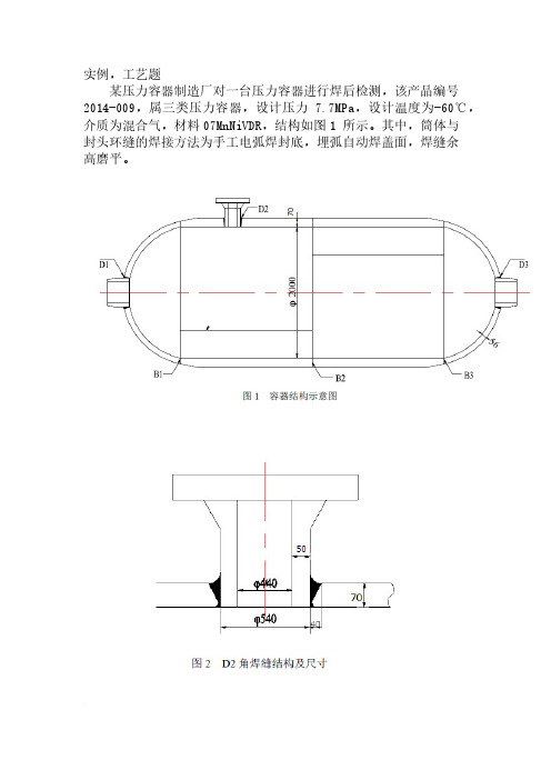
实例,工艺题
某压力容器制造厂对一台压力容器进行焊后检测,该产品编号2014-009,属三类压力容器,设计压力7.7MPa,设计温度为-60℃,介质为混合气,材料07MnNiVDR,结构如图1 所示。
其中,筒体与
封头环缝的焊接方法为手工电弧焊封底,埋弧自动焊盖面,焊缝余
高磨平。
要求:
根据NB/T 47013.3-2015标准,检测技术等级B级,对D2角焊
缝进行超声检测。
填写下表的部分工艺参数。
现有设备及器材:
超声波探伤仪:HS611e(数字机);
直探头: 5P14Z、2.5P20Z;
斜探头:
2.5P13×13K1、K1.5、K2;
5P9×9K1、K1.5、K2、K2.5;
2.5P20×22K1、K1.5、K2;
2.5P9×9K1、K1.5、K2、K2.5。
(说明:小晶片探头前沿长度10mm,大晶片探头前沿长度14mm)。
标准试块:CSK-ⅠA
对比试块: CSK-ⅡA-1、CSK-ⅡA-2、CSK-ⅡA-3、CSK-ⅢA
耦合剂:工业浆糊、机油。
操作指导书编号:XXX 超声检测操作指导书
编制: 日期:。
超声波探头-UTIII

第一节超声波探头一.以构造分类1.直探头: 单晶纵波直探头双晶纵波直探头2.斜探头: 单晶横波斜探头1<L<Ⅱ,双晶横波斜探头单晶纵波斜探头L<1为小角度纵波斜探头L在1附近为爬波探头爬波探头;沿工件表面传输的纵波,速度快、能量大、波长长探测深度较表面波深,对工件表面光洁度要求较表面波松。
(频率波长约,讲义附件11、12、17题部分答案)。
3.带曲率探头: 周向曲率径向曲率。
周向曲率探头适合---无缝钢管、直缝焊管、筒型锻件、轴类工件等轴向缺陷的检测。
工件直径小于2000mm时为保证耦合良好探头都需磨周向曲率。
径向曲率探头适合---无缝钢管、钢管对接焊缝、筒型锻件、轴类工件等径向缺陷的检测。
工件直径小于600mm时为保证耦合良好探头都需磨径向曲率。
4.聚焦探头: 点聚焦线聚焦。
5.表面波探头:(当纵波入射角大于或等于第二临界角,既横波折射角度等于900形成表面波).沿工件表面传输的横波,速度慢、能量低、波长短探测深度较爬波浅,对工件表面光洁度要求较爬波严格。
第一章“波的类型”中学到:表面波探伤只能发现距工件表面两倍波长深度内的缺陷。
(频率波长约,讲义附件11、12题部分答案)。
二.以压电晶体分类:三.压电材料的主要性能参数:1.压电应变常数d33:d33=t/U在压电晶片上加U这么大的应力,压电晶片在厚度上发生了t的变化量,d33越大,发射灵敏度越高(82页最下一行错)。
2.压电电压常数g33:g33=UP/P在压电晶片上加P这么大的应力.在压电晶片上产生UP这么大的电压,g33越大,接收灵敏度越高。
3.介电常数:=Ct/A C-电容、t-极板距离(晶片厚度)、A-极板面积(晶片面积); C小→小→充、放电时间短.频率高。
4.机电偶合系数K:表示压电材料机械能(声能)与电能之间的转换效率。
对于正压电效应:K=转换的电能/输入的机械能。
对于逆压电效应:K=转换的机械能/输入的电能.晶片振动时,厚度和径向两个方向同时伸缩变形,厚度方向变形大,探测灵敏度高,径向方向变形大,杂波多,分辨力降低,盲区增大,发射脉冲变宽.(讲义附件16、19题部分答案)。
UT3无损检测工作技术总结

超声波检测工作技术总结—供热管道焊缝的超声波检测一、概述近几年,由于城市的发展速度和环保的要求,尤其是国家提出“节能减排”计划以来,各地都在对供热公司进行整合重组以求环保、高效,其中集中供热工程因为环境污染小、供热效率高等优点成为了首选,本市也不例外。
受建设单位委托,我在2009年、2010年先后参加了庆阳市西峰区集中供热改造工程管道焊口的超声波检测以及正宁县东区供热改造工程管道焊口超声波检测。
供热管道大多为小径管,小径管曲率半径小、管壁厚度薄,常规超声波检测困难较大。
曲率半径小,普通探头检测接触面小,曲面耦合损失大。
同时超声波在管道内表面发散、反射严重,检测灵敏度低,薄壁又导致较多的杂波。
大量前人的经验以及实验表明利用大K值、小晶片、短前沿的横波探头在寒风两侧进行检测,可以有效地检测出寒风缺陷。
现我把自己在供热管道焊缝超声波检测的一点心得总结如下。
二、检测前准备2.1、检测技术参数管道规格:φ133×4.5, φ79×4管道材质:Q235B焊接方法:手工电弧焊,单面焊检测比例:100%超声波探伤,10%射线抽检检测标准:JB/T4730.3-2005,Ⅱ级合格检测仪器:PCUT-9100,探头:5P6*6K2.5耦合剂:机油、甘油2.2、检测条件的选择(1)、探头的选择晶片尺寸:由于管件为曲面,为了实现和管件的良好耦合,而且晶片尺寸越大探头边缘声束产生的散射也会增加,因此在实际检测中一般选用6mm*6mm、8mm*8mm等尺寸的探头。
探头频率:探头晶片尺寸小指向性较差,管壁薄反射杂波多,为了改善探头指向性和提高分辨力,一般选择较高探测频率的探头(4-6MHz)K值:薄壁管探伤一般选择较大K值探头进行探伤。
因为K值小一次波得声程小,大多在近场区,判断缺陷误差较大,一般选择K2.5、K3。
前沿长度及探头形式:由于管径较小,探伤过程内壁反射发散严重,因此二次波得灵敏度明显比一次波低的多,为了尽可能保证一次波的扫查面积,应选择前沿长度较小的探头,实际检测中一般选择5-8mm。
超声波检测探头
10
12
9.65 13.89
19.29 27.78
38.58 55.56
57.87 83.33
77.16 111.11
115.74 166.67
15 21.70 43.40 86.81 130.21 173.61 260.42
20
25
38.58 60.28
77.16 120.56
154.32 241.13
声束特性
声束轮廓剖面,近场区(焦距,焦点宽度,焦区长度)和扩散角 声束指向角度和偏差
距离幅度特性
反射体-平底孔、横孔或半球体。 距离范围覆盖近场区或焦区。 测量噪声曲线。
等效阻抗
超声波仪器、探头及其组合性能表 (不用电子仪器测试的)
序号 1 2 3 4 5 6 7 8 9 10 11 12 13
双晶直探头
结构
压电晶片 后衬(匹配、吸声、支撑) 楔块 隔声层 外壳 接头
纵波垂直入射 主要参数
频率 晶片尺寸(矩形) 聚焦深度
接触式双晶直探头
应用特点
近场盲区小 声场菱形聚焦不均
匀 窄晶片双晶探头改
善距离波幅特性
接触式聚焦探头
结构
压电晶片 后衬(匹配、吸声、支撑) 透镜楔块 外壳 接头
3 0.48 0.95 1.91 2.86 3.81 5.72
5 1.32 2.65 5.30 7.94 10.59 15.89
近场区表
6 1.91 3.81 7.63 11.44 15.25 22.88
8 3.39 6.78 13.56 20.34 27.12 40.68
10 5.30 10.59 21.19 31.78 42.37 63.56
钢横波近场区表
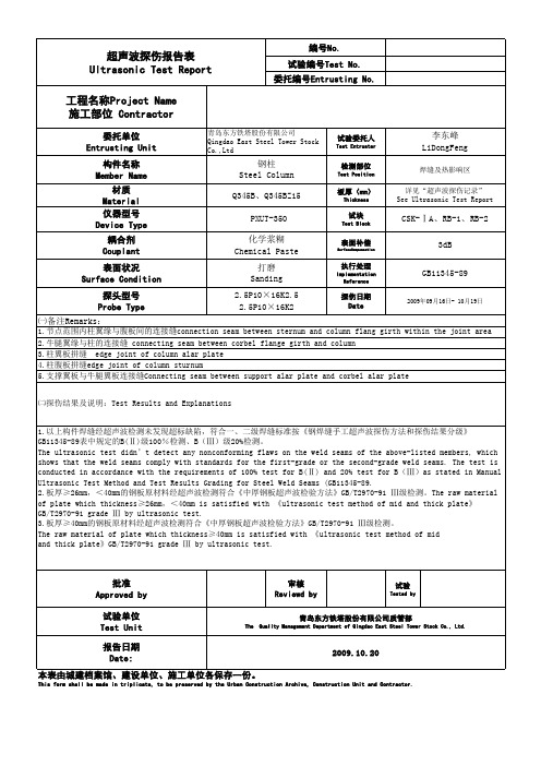
超声波探伤报告UT002
报告日期 Date 本表由城建档案馆、建设单位、施工单位各保存一份。
This form shall be made in triplicate, to be preserved by the Urban Construction Archive, Construction Unit and Contractor.
焊缝Weld Seam 编号 No. (两侧) Both Edges 板厚 (mm) Thickness 焊缝数量 WeldSeamQ uantity 缺陷 编号 DEFECT NO.
青岛东方铁塔股份有限公司 Qingdao East Steel Tower Stock Co.,Ltd
编号 No. 报告编号 Report No. 检测单位 Test Unit
备注 Remarks
合格 一次返修合格 Conformance
Please refer to cover 合格 Conformance remarks 3 for details.
不合格
批准 Approved
审核 Reviewed
检测 Tested by 检测单位名称 Name of Test Unit (公章)(stamp)
2009.10.20
This form shall be made in triplicate, to be preserved by the Urban Construction Archive, Construction Unit and Contractor.
超声波探伤记录 Ultrasonic Test Record 工程名称 Project Name 施工单位 Contractor
超声波探伤报告表 Ultrasonic Test Report 工程名称Project Name 施工部位 Contractor
UTⅢ级专业理论试题(开卷)范围及有关答题说明

⑼ 对缺陷的测定: a.如何测定缺陷当量(波高)?应分别根据 焊缝和锻件不同情况具体测定。 b.明确该工件按JB/T4730标准要求哪些缺陷 (当量值)应记录及进一步测定长度及高 度?实际中应如何测定缺陷的长度及高度? 对锻、铸件及焊缝要按各自特点区别对待。
c.对已测定的缺陷如何根据缺陷当量、波 高、缺陷位置、取向、工件结构、坡口形 式、焊接方法等特点判断取向性质。
⑷ 频率选择 一般选用2.5MHZ,对薄环缝也可选 5MHZ,对锻、铸件可适当降低检测频率。
⑸ 试块和反射体类型的选择 a.焊缝探伤按JB/T4730标准规定及题意对接 焊缝可采用CSK-ⅡA或ⅢA,反射体类型为 Ф2长横孔或Ф1×6短横孔。对奥氏不锈钢焊 缝,铝及铝合金焊缝,钛及钛合金焊缝,管 子环焊பைடு நூலகம்应分别按各自要求选择试块。
二、选择题 20~25题 1、范围 各章内容涉及到的题数 ⑴ 第一章 3~4题 主要涉及物理基础的结论及有关公式表 示形式。
⑵ 第二章 2~3题 主要涉及声场计算,规则反射体规律的 简单计算。 ⑶ 第三章 2~3题 涉及到仪器、探头、试块、原理、特性 及应用等方面内容。
⑷ 第四章、第五章、第六章 每章2~3题 涉及到基本探伤方法、原材料(钢板、 管材、锻件、铸件)。
3、答题要求 ⑴应抓住重点,简明扼要答题。 ⑵对重要内容要预先背诵,有利答题。 ⑶对答不出或答不全的题要尽量多写内容, 不要空白。
四、计算题 3~4题 1、可能出现的计算题范围 ⑴基础理论计算
⑵板材、复合材料计算 ⑶声场计算 ⑷锻件检测计算 ⑸焊缝检测计算
b.对锻件或铸件探伤应选择标准规定的主要 探伤面和辅助探伤面,确保检测到整个铸 (锻件)全体积。
⑵ 对检测面的要求: a.粗糙度要求: 应符合JB/T4730标准中相应规定,如焊缝探 伤和锻件探伤表面粗糙度Ra均应≤6.3μm。
- 1、下载文档前请自行甄别文档内容的完整性,平台不提供额外的编辑、内容补充、找答案等附加服务。
- 2、"仅部分预览"的文档,不可在线预览部分如存在完整性等问题,可反馈申请退款(可完整预览的文档不适用该条件!)。
- 3、如文档侵犯您的权益,请联系客服反馈,我们会尽快为您处理(人工客服工作时间:9:00-18:30)。
第一节超声波探头一.以构造分类1.直探头: 单晶纵波直探头双晶纵波直探头2.斜探头: 单晶横波斜探头1<L<Ⅱ,双晶横波斜探头单晶纵波斜探头L<1为小角度纵波斜探头L在1附近为爬波探头爬波探头;沿工件表面传输的纵波,速度快、能量大、波长长探测深度较表面波深,对工件表面光洁度要求较表面波松。
(频率2.5MHZ波长约2.4mm,讲义附件11、12、17题部分答案)。
3.带曲率探头: 周向曲率径向曲率。
周向曲率探头适合---无缝钢管、直缝焊管、筒型锻件、轴类工件等轴向缺陷的检测。
工件直径小于2000mm时为保证耦合良好探头都需磨周向曲率。
径向曲率探头适合---无缝钢管、钢管对接焊缝、筒型锻件、轴类工件等径向缺陷的检测。
工件直径小于600mm时为保证耦合良好探头都需磨径向曲率。
4.聚焦探头: 点聚焦线聚焦。
5.表面波探头:(当纵波入射角大于或等于第二临界角,既横波折射角度等于900形成表面波).沿工件表面传输的横波,速度慢、能量低、波长短探测深度较爬波浅,对工件表面光洁度要求较爬波严格。
第一章“波的类型”中学到:表面波探伤只能发现距工件表面两倍波长深度内的缺陷。
(频率2.5MHZ波长约1.3mm,讲义附件11、12题部分答案)。
二.以压电晶体分类:三.压电材料的主要性能参数:1.压电应变常数d33:d33=t/U在压电晶片上加U这么大的应力,压电晶片在厚度上发生了t的变化量,d33越大,发射灵敏度越高(82页最下一行错)。
2.压电电压常数g33:g33=UP/P在压电晶片上加P这么大的应力.在压电晶片上产生UP这么大的电压,g33越大,接收灵敏度越高。
3.介电常数:=Ct/A C-电容、t-极板距离(晶片厚度)、A-极板面积(晶片面积); C小→小→充、放电时间短.频率高。
4.机电偶合系数K:表示压电材料机械能(声能)与电能之间的转换效率。
对于正压电效应:K=转换的电能/输入的机械能。
对于逆压电效应:K=转换的机械能/输入的电能.晶片振动时,厚度和径向两个方向同时伸缩变形,厚度方向变形大,探测灵敏度高,径向方向变形大,杂波多,分辨力降低,盲区增大,发射脉冲变宽.(讲义附件16、19题部分答案)。
声速: 3240 M/S 工件厚度: 16.00MM 探头频率: 2.500MC探头K值: 1.96 探头前沿: 7.00MM 坡口类型: X坡口角度: 60.00 对焊宽度: 2.00MM 补偿: -02 dB判废: +05dB 定量: -03dB 评定: -09 dB焊口编号: 0000 缺陷编号: 1. 检测日期: 05.03.09声速: 3240 M/S 工件厚度: 16.00 MM 探头频率: 5.00 MC探头K值: 1.95 探头前沿: 7.00 MM 坡口类型: X坡口角度: 60.00 对焊宽度: 2.00 MM 补偿: -02 dB判废: +05 dB 定量: -03 dB 评定: -09 dB焊口编号: 0000 缺陷编号: 1. 检测日期: 05.03.095.机械品质因子m:m=E贮/E损,压电晶片谐振时,贮存的机械能与在一个周期内(变形、恢复)损耗的能量之比称……损耗主要是分子内摩擦引起的。
m大,损耗小,振动时间长,脉冲宽度大,分辨力低。
m小,损耗大,振动时间短,脉冲宽度小,分辨力高。
6.频率常数Nt:Nt=tf0,压电晶片的厚度与固有频率的乘积是一个常数,晶片材料一定,厚度越小,频率越高. (讲义附件16、19题部分答案)。
7.居里温度Tc:压电材料的压电效应,只能在一定的温度范围内产生,超过一定的温度,压电效应就会消失,使压电效应消失的温度称居里温度(主要是高温影响)。
8.超声波探头的另一项重要指标:信噪比---有用信号与无用信号之比必须大于18 dB。
(为什么?)四.探头型号(应注意的问题)1.横波探头只报K值不报频率和晶片尺寸。
2.双晶探头只报频率和晶片尺寸不报F(菱形区对角线交点深度)值。
例:用双晶直探头检12mm厚的板材,翼板厚度12mm的T型角焊缝,怎样选F值?讲义附件(2题答案)。
五.应用举例:1.斜探头近场N=a b COS/COS。
λ =C S/.直探头近场N=D2/4。
λ=C L/.2.横波探伤时声束应用范围:1.64N-3N。
纵波探伤时声束应用范围:3N。
双晶直探头探伤时,被检工件厚度应在F菱形区内。
3.K值的确定应能保证一次声程的终点越过焊缝中心线,与焊缝中心线的交点到被检工件内表面的距离应为被检工件厚度的三分之一。
4.检测16mm厚的工件用5P 9×9 K2、2.5P9X9K2、2.5P13X13K2那一种探头合适(聚峰斜楔).以5P9X9K2探头为例。
(1).判断一次声程的终点能否越过焊缝中心线?(焊缝余高全宽+前沿)/工件厚度(2).利用公式:N׳(工件内剩余近场长度)=N(探头形成的近场长度)—N״(探头内部占有的近场长度) =axbxcosβ/πxλxcosα–Ltgα/tgβ,计算被检工件内部占有的近场长度。
讲义附件(14题答案)。
A.查教材54页表:COS /COS、tg /tg与K值的关系材料K值 1.0 1.5 2.0 2.5 3有机玻璃COS/ COS0.88 0.78 0.68 0.6 0.52 聚砜COS/ COS0.83 0.704 0.6 0.51 0.44 有机玻璃tg /tg0.75 0.66 0.58 0.5 0.44 聚砜tg /tg0.62 0.52 0.44 0.38 0.33查表可知cosβ/cosα=0.6, tgα/tgβ=0.44, 计算可知α=41.35°.B.λ=C s/ƒ=3.24/5=0.65mmC.参考图计算可知:tgα=L1/4.5, L1=tg41.35°X4.5=0.88X4.5=3.96mm.cosα=2.5/L2, L2=2.5/cos41.5°=2.5/0.751=3.33mm,L=L1+L2=7.3mm, Ltgα/tgβ=7.3×0.44=3.21mm,(N״) 由(1)可知,IS=35.8mm, 2S=71.6mmN=axbxcosβ/xλxcos=9×9×0.6/3.14×0.65=23.81mm, 1.64N=39.1mm, 3N=71.43mm.工件内部剩余的近场(N׳)=N-N״=20.6mm(此范围以内均属近场探伤).(1.64N-N״)与IS比较, (3N-N״)与2S比较,使用2.5P13X13K2探头检测16mm厚工件,1.64N与3N和5P9X9K2探头基本相同,但使用中仍存在问题,2.5P9X9K2探头存在什么问题?一.探伤过程中存在的典型问题:不同探头同一试块的测量结果反射体深度1#探头2#探头横波折射角声程横波折射角声程mm ( 0 ) mm ( 0 )mm20 21.7 21.7 32.8 24.340 24.4 45.0 32.5 49.860 25.8 70 30.9 75.680 28.9 101.8 29.1 102.0注:1.晶片尺寸1313 2.晶片尺寸1020.试验中发现:同一探头(入射角不变)在不同深度反射体上测得的横波折射角不同,进一步试验还发现,折射角的变化趋势与晶片的结构尺寸有关,对不同结构尺寸的晶片,折射角的变化趋势不同,甚至完全相反,而对同一晶片,改变探头纵波入射角,其折射角变化趋势基本不变,上表是两个晶片尺寸不同的探头在同一试块上测量的结果.1#探头声束中心轨迹 2#探头声束中心轨迹1.纵波与横波探头概念不清.第一临界角:由折射定律SinL/C L1=Sin L/C L2,当C L2C L1时,L L,随着L增加,L也增加,当L增加到一定程度时,L=900,这时所对应的纵波入射角称为第一临界角I,I=Sin -1CL1/C L2=Sin-12730/5900=27.60,当L I时,第二介质中既有折射纵波L又有折射横波S.第二临界角:由折射定律Sin L/C L1=Sin S/C S2, 当Cs2C L1时,S L,随着L增加,S也增加,当L增加一定程度时,S=900,这时所对应的纵波入射角称为第二临界角Ⅱ.Ⅱ=Sin-1C L1/C S2=Sin-12730/3240=57.70.当L=I--Ⅱ时,第二介质中只有折射横波S,没有折射纵波L,常用横波探头的制作原理。
利用折射定律判断1#探头是否为横波探头。
A.存横波探伤的条件:Sin27.60/2730=Sin/3240,Sin=Sin27.603240/2730=0.55,=33.360,K=0.66。
B.折射角为21.70时:Sin/2730=Sin21.70/3240,Sin=Sin21.702730/3240,=18.150, 小于第一临界角27.60。
折射角为28.90时:Sin/2730=Sin28.90/3240,Sin= Sin28.902730/3240,=240,也小于第一临界角27.60。
C.如何解释1#探头随反射体深度增加,折射角逐渐增大的现象,由A、B可知,1#探头实际为纵波斜探头,同样存在上半扩散角与下半扩散角,而且上半扩散角大于下半扩散角。
(讲义附件9题答案)。
纵波入射角L由00逐渐向第一临界角I(27.60)增加时,第二介质中的纵波能量逐渐减弱,横波能量逐渐增强,在声束的一定范围内,下区域内的纵波能量大于上区域内的纵波能量,探测不同深度的孔,实际上是由下区域内的纵波分量获得反射回波最高点。
由超声场横截面声压分布情况来看,A点声压在下半扩散角之内,B点声压在上半扩散角之内,且A点声压高于B点声压。
再以近场长度N的概念来分析,2.5P 1313 K1探头N=36.5mm,由此可知反射体深度20mm时,声程约21.7mm,=21.70时N=40.07mm为近场探伤。
在近场内随着反射体深度增加声程增大,A点与B点的能量逐渐向C点增加,折射角度小的探头角度逐渐增大,折射角度大的探头角度逐渐减少。
2.盲目追求短前沿:以2.5P 1313 K2探头为例,b=15mm与b=11mm,斜楔为有机玻璃材料;(1).检测20mm厚,X口对接焊缝,缺陷为焊缝层间未焊透.(2).信噪比的关系:有用波与杂波幅度之比必须大于18dB.(3).为什么一次标记点与二次标记点之间有固定波?由54页表可知:COS/COS=0.68,K2探头=63.44,COS63.44=0.447,COS=0.447/0.68=0.66,COS=6.5/LX,前沿LX=6.5/0.66=9.85mm。
(讲义附件6题答案)。
3.如何正确选择双晶直探头:(1).构造、声场形状、菱形区的选择;(2).用途:为避开近场区,主要检测薄板工件中面积形缺陷.(3).发射晶片联接仪器R口,接收晶片联接T口(匹配线圈的作用).4.探头应用举例:二.超声波探头的工作原理:1.通过压电效应发射、接收超声波。
