333-2USOC中文资料
艾默生UL33-UPS用户手册.doc
iTrust UL33 系列 UPS 系统20kVA/30kVA/40kVA/60kVA用户手册艾默生网络能源有限公司iTrust UL33 系列 UPS 系统用户手册资料版本BOM 编码艾默生网络能源有限公司为客户提供全方位的技术支持,用户可与就近的艾默生办事处或用户服务中心联系,也可直接与公司总部联系。
艾默生网络能源有限公司地址:深圳市南山区科技工业园科发路1号邮编: 518057公司网址:主编:郑凯编委:周岩峰周党生杨志洵审核:郑大鹏肖学礼柏子平吴波杨勇华赵广涛责任编辑:周溶版权声明艾默生网络能源有限公司版权所有,保留一切权利在没有得到本公司书面许可时,任何单位和个人不得擅自摘抄、复制本书(软件等)的一部分或全部,不得以任何形式(包括资料和出版物)进行传播。
版权所有,侵权必究。
内容如有改动,恕不另行通知。
Copyright by Emerson Network Power Co., Ltd.All rights reserved.The information in this document is subject to change without notice. No part of this document may in any form or by any means (electronic, mechanical, micro-copying, photocopying, recording or otherwise) be reproduced, stored in a retrieval system or transmitted without prior written permission from Avansys Power Co., Ltd..出版说明内容介绍本手册主要介绍 iTrust UL33 系列 UPS系统及其组成部分的特点、功能、技术参数、机械参数等,详细说明了外部连接端口的尺寸和电气性能。
博世RF3332产品参数
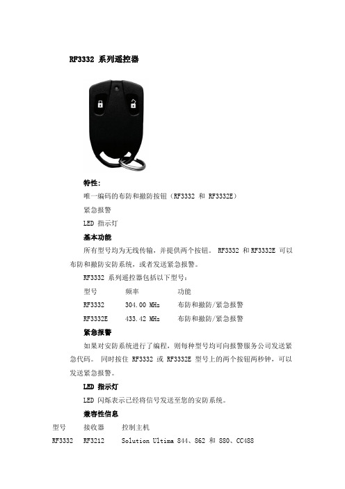
RF3332 系列遥控器特性:唯一编码的布防和撤防按钮(RF3332 和 RF3332E)紧急报警LED 指示灯基本功能所有型号均为无线传输,并提供两个按钮。
RF3332 和RF3332E 可以布防和撤防安防系统,或者发送紧急报警。
RF3332 系列遥控器包括以下型号:型号频率功能RF3332 304.00 MHz 布防和撤防/紧急报警RF3332E 433.42 MHz 布防和撤防/紧急报警紧急报警如果对安防系统进行了编程,则每种型号均可向报警服务公司发送紧急代码。
同时按住 RF3332 或 RF3332E 型号上的两个按钮两秒钟,可以发送紧急报警。
LED 指示灯LED 闪烁表示已经将信号发送至您的安防系统。
兼容性信息型号接收器控制主机RF3332 RF3212 Solution Ultima 844、862 和 880、CC488RF3213 VR-8RF3222 DS7400XiV4RF3224 DS7240、DS7220、D6412 和D4412RF3332E RF3212E Solution Ultima 844、862 和 880、CC488RF3213E VR-8RF3222E DS7400XiV4RF3227E DS7240、DS7220、D6412 和D4412RF3228E MariseRF3249E DA (Abacus)规格:环境要求相对湿度: 0% 至 95%(无冷凝)操作温度: -29°C 至 +65°C(-20°F 至 +150°F)对于 UL 认证的安装,所需温度范围为 0°C 至 +49°C(+32°F 至 +120°F)机械特性尺寸: 3.8 厘米 x 6.3 厘米 x 1.3 厘米(1.5 英寸 x 2.5 英寸 x0.5 英寸)电源要求电池:两节 3 VDC 锂电池电池寿命:当使用推荐的电池类型时,在正常操作条件下,电池寿命约为 5 年发射特性最大射频功率:小于 10 mW频率RF3332E: 433.42 MHzRF3332: 304.00 MHz。
CPU222介绍
CPU222介绍返回TOPCPU 222 技术规范CPU 222 DC/DC/DC CPU 222 AC/DC/ 继电器物理特性尺寸(W X H X D) 90 x 80 x 62 mm 90 x 80 x 62 mm重量270 g 310 g功耗 5 W 7 W存储器特性程序存储器在线程序编辑时4096 bytes 4096 bytes非在线程序编辑时4096 bytes 4096 bytes数据存储器2048 bytes 2048 bytes装备(超级电容) 50小时/典型值(40°C时最少8小时) 50小时/典型值(40°C时最少8小时)(可选电池) 200天/典型值200天/典型值I/O特性本机数字量输入8 输入8 输入本机数字量输出 6 输出 6 输出本机模拟量输入无无本机模拟量输出无无数字I/O映象区256(128输入/128输出) 256(128输入/128输出) 模拟I/O映象区32(16输入/16输出) 32(16输入/16输出)允许最大的扩展I/O模块2个模块2个模块允许最大的智能模块2个模块2个模块脉冲捕捉输入8 8高速计数器总数4个4个单相计数器4,每个30KHz 4,每个30KHz 两相计数器2,每个20KHz 2,每个20KHz脉冲输出2个20KHz(仅限于DC输出) 2个20KHz(仅限于DC输出)定时器总数256个256个1ms 4个4个10ms 16个16个100ms 236个236个计数器总数256(由超级电容或电池备份) 256(由超级电容或电池备份)内部存储器位掉电保持256(由超级电容或电池备份) 256(由超级电容或电池备份)112(存储在EEPROM) 112(存储在EEPROM)时间中断2个1ms分辨率2个1ms分辨率边沿中断4个上升沿和/或4个下降沿4个上升沿和/或4个下降沿模拟电位器1个8位分辨率1个8位分辨率布尔量运算执行时间0.22μs0.22μs时钟可选卡件可选卡件卡件选项存储器、电池和实时时钟存储器、电池和实时时钟接口1个RS-485接口1个RS-485接口PPI,DP/T波特率9.6,19.2和187.5kbaud 9.6,19.2和187.5kbaud自由口波特率 1.2kbaud至115.2kbaud 1.2kbaud至115.2kbaud每段最大电缆长度使用隔离的中继器:187.5kbaud可达1000米,38.4kbaud可达1200米使用隔离的中继器:187.5kbaud可达1000米,38.4kbaud可达1200米未使用隔离中继器:50米未使用隔离中继器:50米每段32个站,每个网络126个站每段32个站,每个网络126个站最大站点数32 32最大主站数是(NETR/NETW) 是(NETR/NETW)点到点(PPI主站模式) 共4个,2个保留共4个,2个保留MPI连接(1个给PG,1个给OP) (1个给PG,1个给OP)输入电源输入电压20.4至28.8 VDC 85至264 VAC(47至63 Hz) 输入电流85mA (仅CPU,24 VDC) 40/20mA (仅CPU,120/240VAC)500mA (最大负载,24 VDC) 140/70mA (最大负载,120/240 VAC)冲击电流12A,28.8 VDC时20A,264 VAC时隔离(现场与逻辑) 不隔离1500 VAC保持时间(掉电) 10ms,24 VDC时20/80ms,120/240 VAC时保险(不可替换) 3A,250 V时慢速熔断2A,250 V时慢速熔断传感器电压L+减5V 20.4至28.8 VDC电流限定 1.5A峰值,终端限定非破坏性1.5A峰值,终端限定非破坏性纹波噪声来自输入电源小于1 V峰分值隔离(传感器与逻辑) 非隔离非隔离本机集成数字量输入点数8输入8输入输入类型漏型/源型(IEC类型1/漏型) 漏型/源型(IEC类型1/漏型) 额定电压24 VDC,4mA典型值时24 VDC,4mA典型值时最大持续允许电压30V DC 30V DC浪涌电压35V DC,0.5秒35V DC,0.5秒逻辑1信号(最小) 15 VDC,2.5mA 15 VDC,2.5mA逻辑0信号(最大) 5 VDC,1mA 5 VDC,1mA输入延迟可选(0.2至12.8ms) 可选(0.2至12.8ms)连接2线接近开关传感器(Bero)允许漏电流最大1mA 1mA隔离(现场与逻辑)光电隔离是是隔离组500 VAC,1分钟500 VAC,1分钟高速输入速率见接线图见接线图高速计数器逻辑1=15–30 VDC高速计数器逻辑20KHz(单相),10KHz(两相) 20KHz(单相),10KHz(两相)触点寿命- 100,000(额定负载)同时接通的输出55°C时,所有的输出(水平安装) 55°C时,所有的输出(水平安装)45°C时,所有的输出(垂直安装) 45°C时,所有的输出(垂直安装)两个输出并联是,仅输出同组时否电缆长度(最大)屏蔽500米500米非屏蔽150米150米返回TOPCPU 222 DC/DC/DC 接器端子图返回TOPCPU 222 尺寸图。
Ruckus美国优科无线产品介绍大全
RUCKUS美国优科无线产品介绍大全《产品目录》无线控制器- ZoneDirector 3000系列 (3)无线控制器 - ZoneDirector 1000系列 (10)无线接收器 - 室内11n ZoneFlex 7942 (15)无线接收器 - 室外11n ZoneFlex 7942-OT (21)无线接收器 - 室内11g ZoneFlex 2942 (27)无线接收器 - 室外11g ZoneFlex 2942-OT (35)无线接收器 - 室外大功率(500mw)ZoneFlex 2741 (40)无线接收器- 室内双频11n ZoneFlex 7962 (48)无线接收器- 室外双频11n ZoneFlex 7762 (54)无线接收器- 室内大功率(500mw)ZoneFlex 2942-FB (60)无线接收器- 室外大功率(500mw)ZoneFlex 2942-FBOT (65)无线网络管理系统– FlexMaster (72)无线控制器- ZoneDirector 3000系列Ruckus ZoneDirector 3000是首个企业级智能无线局域网系统,它在一个很低的总体拥有成本上,提供了一个安全、可靠,同时又易于扩展的无线局域网解决方案。
Ruckus ZoneDirector 3000的设计理念力求简洁而易用,通过一个中央点,其最多可以管理500台ZoneFlex 802.11b/g和802.11n,以及室内室外的智能无线AP。
完全不像传统的无线局域网那么昂贵、复杂、难以部署,对任何一个需要高性能无线局域网而又期望其易于实施和管理的企业来说,选用ZoneDirector 3000都是再合适不过的了。
ZoneDirector 3000集成了很多高级的功能,诸如智能天线操纵,智能无线网状结构,以及动态无线安全等,这些都是你在其他的WLAN系统中见不到的。
Ruckus ZoneDirector 3000可以由非无线网络专业人员进行部署和操作,安装非常快速简便。
单片机瘤原理与应用

单片机原理与应 用
实习内容:
DS18B20温度 LED灯流水灯显 示独立按键控 制液晶实验
单片机的定义
单片机是指一个集成在一块芯片上的完整计算机系统。 尽管他的大部分功能集成在一块小芯片上,但是它具有 一 个完整计算机所需要的大部分部件:CPU、内存、内部 和 外部总线系统,目前大部分还会具有外存。同时集成诸 如 通讯接口、定时器,实时时钟等外围设备。而现在最强 大 的单片机系统甚至可以将声音、图像、网络、复杂的输 入 输出系统集成在一块芯片上。
ATMEL单片机(51单片机):ATMEl公司的8位单片机有AT89、AT90两个 系列,AT89系列是8位Flash单片机,与8051系列单片机相兼容,静态时钟模 式; AT90系列单片机是增强RISC结构、全静态工作方式、内载在线可编程 Flash 的单片机,也叫AVR单片机.
PHLIPIS 51PLC系列单片机(51单片机):PHILIPS 公司的单片机是基 于 80C51内核的单片机,嵌入了掉电检测、模拟以及片内RC振荡器等功能, 这使 51LPC在高集成度、低成本、低功耗的应用设计中可以满足多方面 的性能要 求.
RS2253 三路双通道模拟多路复用 多路解复用 CMOS 电路芯片说明书

CMOS Triple 2-Channel Analog Multiplexer/DemultiplexerFEATURES•-3dB Bandwidth: 180MHz•Single Supply Operation +2.5V to +5.5V •Low ON Resistance, 48Ω(TYP) With 5V Supply•High Off-Isolation: -83dB (RL = 50Ω,f = 1MHz)•Break-Before-Make Switching•Binary Address Decoding on Chip •Operating Temperature Range:-40°C to +125°C•PACKAGES: SOIC-16(SOP16), SSOP-16, TSSOP-16 and QFN-3×3-16LAPPLICATIONS•Sensors•Analog and Digital Multiplexing and Demultiplexing•A/D and D/A Conversion•Signal Gating•Battery-Operated Equipment•Factory Automation•Appliances•Communications Circuits DESCRIPTIONThe RS2253 is a CMOS analog IC configured as three single-pole/double-throw (SPDT) switches. This CMOS device can operate from 2.5 V to 5.5 V.The RS2253 device are digitally-controlled analog switches. It has low on-resistance (48Ω TYP) and very low off-leakage current (1nA TYP).The RS2253 is available in Green SOIC-16, SSOP-16, TSSOP-16 and QFN-3×3-16L packages. It operates over an ambient temperature range of -40°C to +125°C.Functional Diagrams of RS2253PIN CONFIGURATIONS(TOP VIEW)SOIC-16(SOP16)/SSOP-16/TSSOP-16ENABLEYV CC X X1X0B CAXNC QFN-3×3-16LAX0X1(TOP VIEW)PIN DESCRIPTIONFUNCTION TABLEX=Don’t careNOTE: Input and output pins are identical and inter-changeable. Either may be considered an input or output; signals pass equally well in either direction.ABSOLUTE MAXIMUM RATINGS(1)V CC to GND..........................................................−0.3 to 6VInput Terminals, Voltage. (2) .................– 0.3 to (V+) + 0.3V Continuous Current into Any Terminal......................±20mAPeak Current, X_(Pulsed at 1ms,10% duty cycle)…………………….. ±40mA Storage Temperature ……….……………−65°C to +150°C Operating Temperature ……….…….……−40°C to +125°C Junction Temperature...............................................+150°C Package Thermal Resistance @ T A = +25°CQFN-3×3-16L………………….………..……………. 80°C/WSSOP-16……….…………........................................64°C/WSOIC-16, TSSOP-16………….……….…………….100°C/WLead Temperature (Soldering, 10s) …………….........260°CESD SusceptibilityHBM (1000V)MM (100V)(1) Stresses above these ratings may cause permanent damage. Exposureto absolute maximum conditions for extended periods may degradedevice reliability. These are stress ratings only, and functionaloperation of the device at these or any other conditions beyond thosespecified is not implied.(2) Input terminals are diode-clamped to the power-supply rails. Inputsignals that can swing more than 0.3V beyond the supply rails shouldbe current-limited to 10mA or less.PACKAGE/ORDERING INFORMATIONPRODUCT ORDERING NUMBER TEMPERATURERANGEPACKAGE LEADPACKAGEMARKINGPACKAGE OPTIONRS2253 RS2253XS16 -40°C ~+125°C SOIC-16(SOP16) RS2253 Tape and Reel,3000 RS2253XSS16 -40°C ~+125°C SSOP-16 RS2253 Tape and Reel,3000 RS2253XTSS16 -40°C ~+125°C TSSOP-16 RS2253 Tape and Reel,3000 RS2253XTQC16 -40°C ~+125°C QFN-3×3 -16L RS2253 Tape and Reel,3000ESD damage can range from subtle performancedegradation to complete device failure. Precisionintegrated circuits may be more susceptible todamage because very small parametric changescould cause the device not to meet its publishedspecifications.ESD SENSITIVITY CAUTIONELECTRICAL CHARACTERISTICSV CC = 5.0 V or 3.3V, FULL= –40°C to +125°C,Typical values are at TA = +25°C. (unless otherwise noted)(1) All unused digital inputs of the device must be held at V IO or GND to ensure proper device operation.ELECTRICAL CHARACTERISTICS (continued)V CC= 5.0 V or 3.3V, FULL= –40°C to +125°C Typical values are at TA = +25°C (unless otherwise noted)TYPICAL CHARACTERISTICSParameter Measurement InformationTest Circuit 1. Address Transition Times (t TRANS)Test Circuit 2. Switching Times (t ON, t OFF)Test Circuit 3. Break-Before-Make Time Delay (t D)Parameter Measurement Information (continued)Test Circuit 4. Charge Injection (Q)Test Circuit 5. Off Isolation, On LossTest Circuit 6. CapacitanceAPPLICATION NOTESThe RS2253 device is a triple 2-channel multiplexer having three separate digital control inputs, A, B, and C, and an inhibit input. Each control input selects one of a pair of channels which are connected in a single-pole, double-throw configuration.When the devices are used as demultiplexers, the CHANNEL IN/OUT terminals are the outputs and the COMMON OUT/IN terminals are the inputs.BINARY TO 1 OF 2Figure 1. The RS2253 Functional Block DiagramPACKAGE OUTLINE DIMENSIONSSOIC-16RECOMMENDED LAND PATTERN (Unit: mm)SSOP-16RECOMMENDED LAND PATTERN (Unit: mm)TSSOP-16RECOMMENDED LAND PATTERN (Unit: mm)QFN-3x3-16LSIDE VIEWTOP VIEW BOTTOM VIEW(Unit: mm)。
中文Socomec Resys M40

否 否 否 是 否 否
• •
预 报 警功能 当故障电流超过动作值的 50%,预报警输出触点动作(若选)。当故障电流下降至预设值的 30%,该触点将自动 复位。 使用 DIP 开关 A 与 B 来选择继电器的动作方式。当选择正向安全,继电器通常处于励磁(闭合)状态,当发生故 障时处于失磁(打开)状态。当选择负向安全,继电器通常处于失磁(打开)状态,当发生故障时处于励磁(闭 合)状态。
The information provided in this literature is believed to be accurate (subject to change without prior notice); however, use of such information shall be 50m* m ax. entirely at the user’s own risk.
PDF 文件使用 "pdfFactory Pro" 试用版本创建
L1 L2 L3 N E
• 安装详图
30mm 44mm 49.5mm 63.5mm
1
2
3
4
5
6
7
*Dual voltage only available 只在 115V/230V AC 是作为 as 115V/230V AC. For 115V, connect across 双电源。 terminals 6 and 7 使用 115V 时连接端子 6 和 7。 For all other voltages, 使用其他电压等级电源时连接 connect across terminals 5 and 端子 5 和 7。 7.
标准:
A B C D
•
CSU8RF322X_电饭煲直发器芯片应用手册

带 12-bit ADC 的 8 位 RISC FLASH MCU 使用指南 REV 1.2.3
Rev.1.2.3
第 1 页,共 89 页
CSU8RF3221/CSU8RF3222/CSU8RF3223
版本历史
历史版本. REV 1.0 REV 1.1 REV 1.2
REV 1.2.1 REV 1.2.2 REV 1.2.3
修改内容 初始版本 换新 LOGO 初始版本 1、增加 1.4V 校准方法 2、更新存储器框图 3、增加 E2PROM 82FH 处所存放数据
的说明 4、更正早期版本的笔误 1、修改时钟系统信息 1、修改 IDD2 的笔误 2、修改电气特性中 IDD3 的笔误 1、修改 CPU 核的功能模块图 2、增加 LVR 3.6V 功能
版本历史
版本日期 2012-09-01 2013-01-28 2013-02-20
2013-02-22 2013-03-13 2013-4-11
Rev.1.2.3
第 2 页,共 89 页
CSU8RF3221/CSU8RF3222/CSU8RF3223
目录
目录
版本历史 ................................................................................................................................................................. 2
目 录 ...................................................................................................................................................................... 3
ATMEL CPU卡及其操作系统
片处于完全工作状态时电流的 15% • 休眠模式 芯片上一切活动均被挂起 RAM 中还保留数据 在休眠状态下 芯片的
电流通常低于 15µA 最低可达到 0.6µA 同时 由于芯片使用静态逻辑设计 无须时钟持续工作 这就是说 在等待一个内部事件 的触发时 时钟频率可以减缓 甚至停止 安全特性 AT89SC 系列微处理器提供了下述安全特性 • 低电压保护 • 低频保护 防止静态分析 • 高频滤波 防止干扰 • 传输代码 保护芯片在运输过程中不被盗用 • 唯一系列代码 当时钟频率低于 500KHz 或电压低于 4V 时 芯片会产生一个安全保护中断 当时钟频率高于 10MHz 或电压低于 3V 时 芯片处于复位状态 直至电压或时钟频率恢复
Select File 功能
此命令使用文件名或应用标示符来选择 IC 卡内 DF 或 EF
格式 代码值 CLA‘00’INS‘A4’P1‘00’P2‘00’Lc‘00’ 选择 MF 文件 / ‘02’Data 无 / FID
Get Challenge 功能
此命令请求 IC 卡返回一个用于安全相关过程的随机数
SF 是密码文件 各层目录均可有一个 存放用户密码 KF 是密钥文件 各层目录均可有一个 存放发行商密钥 WF 是工作文件 数据文件 EF 支持两种标准 EF 文件结构 线性定长记录 透明二进制 本结构支持一卡多用
333U说明书(中文)

(3) 选择的单位必须与装置单位匹配,否则 Tri-Loop 将发出报警。确认仪表的单位分配。
罗斯蒙特和罗斯蒙特徽标是罗斯蒙特股份有限公司的注册商标。 Tri-Loop、 Multivariable (多变量)、 MV 和 Hot Backup (热备份)是罗斯蒙特股份有限公司的商标。 HART 是 HART 通讯基金会的注册商标。 所有其他标记归各自业主所有。 ©1996、 1997 罗斯蒙特股份有限公司版权所有。 罗斯蒙特 3095 MV 型多变量质量流量变送器受到下列一项或多项美国专利保护:4,370,890、 4,612,812、 4,791,352、 4,798,089、 4,818,994、 4,833,922、4,866,435、4,926,340、5,028,746,并受到墨西哥 154,961 号专利保护 。罗斯蒙特 3244MV 型智能温度变送器以及 HART Tri-Loop 受到一项或多项美国专利保护。其他美国专利和外国专利正在申请中。
满刻度 (20 mA) 值 ___________________________(2) _______________________________________________(2(3)
F 激活
F 禁用 +
F 第一变量
F 第二变量
F 第三变量
F 第四变量 +
零 (4 mA) 值 _________________________________(2)
易于组态和安装
利用 275/375 通讯器,可轻松对 333 HART Tri-Loop 进行组态和维护。AMS 设备管理配套软件和工程助手 软件 (5.0 或更高版本)可提供基于微机的简易用户 组态。利用三个 DIN 导轨安装选项以及便于灵活接地 的电气绝缘模拟输出通道,可实现快速轻松的安装。
2SK1933中文资料
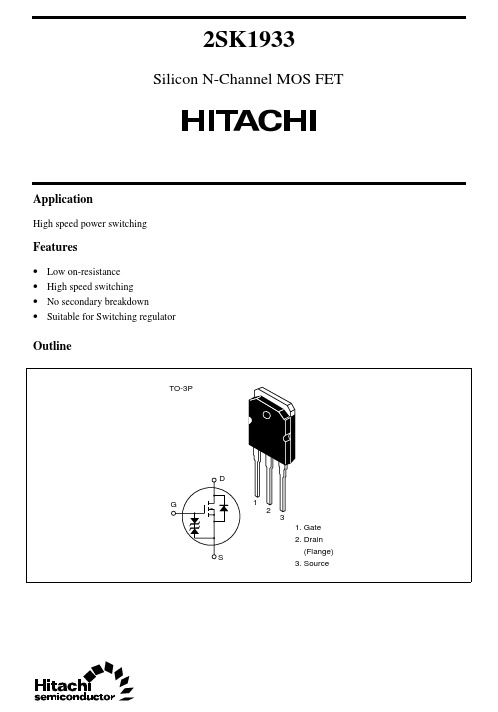
2SK1933Silicon N-Channel MOS FETApplicationHigh speed power switchingFeatures• Low on-resistance• High speed switching• No secondary breakdown• Suitable for Switching regulatorOutline2SK19332Absolute Maximum Ratings (Ta = 25°C)ItemSymbol Ratings Unit Drain to source voltage V DSS 900V Gate to source voltage V GSS ±30V Drain current I D10A Drain peak currentI D(pulse)*130A Body to drain diode reverse drain current I DR 10A Channel dissipation Pch*2150W Channel temperature Tch 150°C Storage temperatureTstg–55 to +150°CNotes 1.PW ≤ 10 µs, duty cycle ≤ 1 %2.Value at Tc = 25°C2SK19333Electrical Characteristics (Ta = 25°C)ItemSymbol Min Typ Max Unit Test conditions Drain to source breakdown voltageV (BR)DSS 900——V I D = 10 mA, V GS = 0Gate to source breakdown voltageV (BR)GSS ±30——V I G = ±100 µA, V DS = 0Gate to source leak current I GSS ——±10µA V GS = ±25 V, V DS = 0Zero gate voltage drain current I DSS——250µA V DS = 720 V, V GS = 0Gate to source cutoff voltage V GS(off) 2.0— 3.0V I D = 1 mA, V DS = 10 V Static drain to source on state resistanceR DS(on)—0.9 1.2ΩI D = 5 A V GS = 10 V*1Forward transfer admittance |y fs | 4.57—S I D = 5 A V DS = 20 V*1Input capacitance Ciss —2620—pF V DS = 10 V Output capacitanceCoss —830—pF V GS = 0Reverse transfer capacitance Crss —320—pF f = 1 MHz Turn-on delay time t d(on)—30—ns I D = 5 A Rise timet r —140—ns V GS = 10 V Turn-off delay time t d(off)—285—ns R L = 6 ΩFall timet f —170—ns Body to drain diode forward voltageV DF —0.9—V I F = 10 A, V GS = 0Body tp drain diode reverse recovery time t rr—1600—nsI F = 10 A, V GS = 0,di F / dt = 100 A / µs Note1.Pulse Test2SK193342SK193352SK193362SK193372SK19338Hitachi CodeJEDECEIAJWeight (reference value)TO-3P—Conforms5.0 gUnit: mmCautions1.Hitachi neither warrants nor grants licenses of any rights of Hitachi’s or any third party’s patent,copyright, trademark, or other intellectual property rights for information contained in this document.Hitachi bears no responsibility for problems that may arise with third party’s rights, includingintellectual property rights, in connection with use of the information contained in this document.2.Products and product specifications may be subject to change without notice. Confirm that you have received the latest product standards or specifications before final design, purchase or use.3.Hitachi makes every attempt to ensure that its products are of high quality and reliability. However,contact Hitachi’s sales office before using the product in an application that demands especially high quality and reliability or where its failure or malfunction may directly threaten human life or cause risk of bodily injury, such as aerospace, aeronautics, nuclear power, combustion control, transportation,traffic, safety equipment or medical equipment for life support.4.Design your application so that the product is used within the ranges guaranteed by Hitachi particularly for maximum rating, operating supply voltage range, heat radiation characteristics, installationconditions and other characteristics. Hitachi bears no responsibility for failure or damage when used beyond the guaranteed ranges. Even within the guaranteed ranges, consider normally foreseeable failure rates or failure modes in semiconductor devices and employ systemic measures such as fail-safes, so that the equipment incorporating Hitachi product does not cause bodily injury, fire or other consequential damage due to operation of the Hitachi product.5.This product is not designed to be radiation resistant.6.No one is permitted to reproduce or duplicate, in any form, the whole or part of this document without written approval from Hitachi.7.Contact Hitachi’s sales office for any questions regarding this document or Hitachi semiconductor products.Hitachi, Ltd.Semiconductor & Integrated Circuits.Nippon Bldg., 2-6-2, Ohte-machi, Chiyoda-ku, Tokyo 100-0004, Japan Tel: Tokyo (03) 3270-2111 Fax: (03) 3270-5109Copyright ' Hitachi, Ltd., 1999. All rights reserved. Printed in Japan.Hitachi Asia Pte. Ltd.16 Collyer Quay #20-00Hitachi TowerSingapore 049318Tel: 535-2100Fax: 535-1533URLNorthAmerica : http:/Europe : /hel/ecg Asia (Singapore): .sg/grp3/sicd/index.htm Asia (Taiwan): /E/Product/SICD_Frame.htm Asia (HongKong): /eng/bo/grp3/index.htm Japan : http://www.hitachi.co.jp/Sicd/indx.htmHitachi Asia Ltd.Taipei Branch Office3F, Hung Kuo Building. No.167, Tun-Hwa North Road, Taipei (105)Tel: <886> (2) 2718-3666Fax: <886> (2) 2718-8180Hitachi Asia (Hong Kong) Ltd.Group III (Electronic Components)7/F., North Tower, World Finance Centre,Harbour City, Canton Road, Tsim Sha Tsui,Kowloon, Hong Kong Tel: <852> (2) 735 9218Fax: <852> (2) 730 0281 Telex: 40815 HITEC HXHitachi Europe Ltd.Electronic Components Group.Whitebrook ParkLower Cookham Road MaidenheadBerkshire SL6 8YA, United Kingdom Tel: <44> (1628) 585000Fax: <44> (1628) 778322Hitachi Europe GmbHElectronic components Group Dornacher Stra§e 3D-85622 Feldkirchen, Munich GermanyTel: <49> (89) 9 9180-0Fax: <49> (89) 9 29 30 00Hitachi Semiconductor (America) Inc.179 East Tasman Drive,San Jose,CA 95134 Tel: <1> (408) 433-1990Fax: <1>(408) 433-0223For further information write to:。
U-CONTROL UCA222 使用说明书

使用说明书U-CONTROL UCA222Ultra-Low Latency 2 In/2 Out USB Audio Interface with Digital Output序言感谢您选择了 UCA222 U-CONTROL! 它是一款高性能接口, 设有可与电脑笔记本或录音棚 (需使用台式电脑)中必须的录音设备相连接的 USB 接口。
UCA222 可与PC 及 MAC 电脑相兼容, 且无需独立的安装。
由于结构坚固, 便于携带的特点, 所以非常适合旅行时携带。
独立的耳机输出端令您随时收听录制的音乐, 即使没有喇叭也没关系。
另外, 它设有 2 个输入及 2 个输出端及 S/PDIF 输出端, 这为您连接调音台, 喇叭和耳机提供了极大的便利。
UCA222 可用 USB 供电, LED 指示灯可快速检查是否连接好。
它是每位电脑音乐人不可缺少的工具。
目录序言 (2)重要的安全须知 (3)法律声明 (4)保修条款 (4)1...启动之前. (5)2...系统要求 (6)3...控制与接口 (6)4...软件安装. (7)5...基本操作. (7)6...应用图.. (8)7...音频连接. (10)8...技术参数. (10)带有此标志的终端设备具有强大的电流, 存在触电危险。
仅限使用带有 ¼'' TS 或扭锁式插头的高品质专业扬声器线。
所有的安装或调整均须由合格的专业人员进行。
此标志提醒您, 产品内存在未绝缘的危险电压, 有 触电危险。
此标志提醒您查阅所附的重要的使用及维修说明。
请阅读有关手册。
小心为避免触电危险,请勿打开机顶盖 (或背面挡板)。
设备内没有可供用户维修使用的部件。
请将维修事项交由合格的专业人员进行。
小心为避免着火或触电危险, 请勿将此设备置于雨淋或潮湿中。
此设备也不可受液体滴溅, 盛有液体的容器也不可置于其上, 如花瓶等。
小心维修说明仅是给合格的专业维修人员使用的。
ESP32-S2-Solo-2 模组技术规格书说明书

P RE LI MI N A R YESP32S2SOLO2ESP32S2SOLO2U技术规格书2.4GHz WiFi (802.11b/g/n)模组内置ESP32S2系列芯片(版本v1.0),Xtensa ®单核32位LX7微处理器flash 最大可选16MB ,内置芯片可叠封2MB PSRAM 36个GPIO ,丰富的外设板载PCB 天线或外部天线连接器ESP32S2SOLO2ESP32S2SOLO2U预发布v0.5乐鑫信息科技版权©2022P RE LI MI N A R1模组概述1.1特性CPU 和片上存储器•内置ESP32-S2或ESP32-S2R2芯片,Xtensa ®单核32位LX7微处理器,支持高达240MHz 的时钟频率•128KB ROM •320KB SRAM •16KB RTC SRAM•2MB PSRAM (仅ESP32-S2R2芯片)WiFi•802.11b/g/n•802.11n 模式下数据速率高达150Mbps •帧聚合(TX/RX A-MPDU,RX A-MSDU)•0.4µs 保护间隔•工作信道中心频率范围:2412~2484MHz 外设•GPIO 、SPI 、UART 、I2C 、I2S 、LCD 接口、Camera 接口、IR 、脉冲计数器、LED PWM 、TWAI ®(兼容ISO 11898-1,即CAN 规范2.0)、全速USB OTG 、ADC 、DAC 、触摸传感器、温度传感器、通用定时器、看门狗定时器模组集成元件•40MHz 集成晶振•最大16MB Quad SPI flash天线选型•板载PCB 天线(ESP32-S2-SOLO-2)•通过连接器连接外部天线(ESP32-S2-SOLO-2U)工作条件•工作电压/供电电压:3.0~3.6V •工作环境温度:–85°C 版模组:–40~85°C–105°C 版模组:–40~105°C (仅ESP32-S2-SOLO-2-H4和ESP32-S2-SOLO-2U-H4)1.2描述ESP32-S2-SOLO-2和ESP32-S2-SOLO-2U 是通用型Wi-Fi MCU 模组,功能强大,具有丰富的外设接口,可用于可穿戴电子设备、智能家居等场景。
ZMM55C6V2中文资料(secos)中文数据手册「EasyDatasheet - 矽搜」

5.8 6.2 6.6
6.4 6.8 7.2
7.0 7.5 7.9
7.7 8.2 8.7
8.5 9.1 9.6
9.4 10 10.6
10.4 11 11.6
11.4 12 12.7
12.4 13 14.1
13.8 15 15.8
15.3 16 17.1
16.8 18 19.1
18.8 20 21.2
5
15
70
1.0
5
20
70
1.0
5
20
90
1.0
5
26
110
1.0
5
30
110
1.0
5
40
170
1.0
5
50
170
1.0
5
55
220
1.0
5
55
220
1.0
5
80
220
1.0
5
80
220
1.0
5
80
220
1.0
5
80
220
1.0
5
80
220
1.0
2.5
90
500
1.0
2.5
90
600
1.0
2.5
110
符号
Min.
热阻Junctiobn到环境空气
RθJA
-
正向电压@I
F=200mA
VF
-
*有效规定,导致在从情况下,距离为10mm防护持在环境温度下
Typ. Max. Unit
-
0.3 * K /毫瓦
-
1.0
微网国际 2U机箱式储能电源一体机规格书
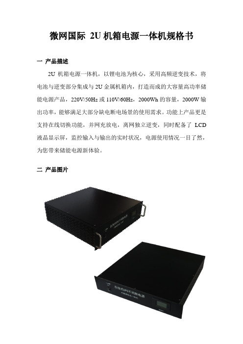
微网国际2U机箱电源一体机规格书一产品描述2U机箱电源一体机,以锂电池为核心,采用高频逆变技术,将电池与逆变部分集成与2U金属机箱内,打造而成的大容量高功率储能电源产品,220V/50Hz或110V/60Hz,2000Wh的容量,2000W输出功率,能够满足大部分缺电断电场景的使用需求。
功能上产品更是支持在线切换功能,并网充放电,离网独立逆变,同时配备了LCD 液晶显示屏,监控输入与输出的实时状况,电源使用情况一目了然,为您带来储能电源新体验。
二产品图片三 面板功能简介及使用说明1. 前面板说明2.后面板说明使用说明:1. 交流输出:打开位于前面板上的交流输出开关,输出显示器,电量显示灯亮起,若电量较低,建议及时给电源充电再进行使用),将设备的电源线插入本产品交流输出母座中,开启设备即可使用。
当产品作为UPS 使用时,请将产品配送的交流输入电源线插头插入家用交流插座,另一品字头端插入产品的交流输入接口。
再将设备电源线接入产品的交流输出母座中,此时由交流市电为设备供电并为内部的电池组充电。
打开产品的交流输出开关即可作为UPS 使用,当突然停电的时候,则自动切换成产品内部电池为负载供电。
作为UPS输出显示器电量显示 交流输入母座 交流输出母座开关使用时,设备总功率请不要超过机器本身的最大输出功率。
机器本身的额定输出功率为2000W,如果负载的运行功率超过2000W,电源则进入保护状态无法输出。
去掉多余的负载,重启电源即可正常使用。
2.充电说明:将本机标配的电源线一端插入市电插座,另一端插入本机交流输入接口,即可为本机充电。
四产品电性参数产品型号2U电池容量12V 180Ah / 2000Wh输出功率额定2000W (3000V A)输入电压AC 85~265V 50/60Hz输出电压220V 50Hz / 110V 60Hz输出波形纯正弦波在线切换断电自动切换切换时间≤5毫秒超载超载后交流输出断开,指示灯亮红色,断开负载,重启恢复短路短路后交流输出断开,断开负载,重启恢复充电时间8小时12小时重量12Kg20Kg尺寸46*44*9cm颜色黑色五工作原理示意图在市电正常的情况下,由市电给设备供电,同时给本产品充电。
海洋控制KTA-223 USB可扩展的控制器说明书

Ocean Controls KTA-223 Arduino Compatible USB Relay Controller•8 Relay Outputs 5A 250VAC• 4 Opto-Isolated Inputs 5-30VDC• 3 Analog Inputs (10 bit)•Connections via Pluggable Screw Terminals•0-5V or 0-20mA Analog Inputs, Jumper Selectable•5A Relay Switching•Power Indicator LED•All enclosed in Professional looking plastic case•Arduino Compatible•Accepts Arduino Shields (Ethernet / XBEE)•USB Virtual COM or RS485 Input•Easily connect multiple units far apart by RS485The KTA-223 is a USB or RS485 controlled IO module for interfacing PCs to real world applications, such as controlling lights and sprinkler systems, reading sensors and monitoring switches and other digital signals. The Relays are capable of switching up to 5A at 250VAC, 10A at 120VAC and 10A at 24VDC but the PCB tracks will only handle up to about 5A. A simple ASCII protocol allows control from Windows/Mac/Linux using either USB Virtual COM drivers or RS485. Additionally, multiple devices can be connected to one RS485 bus, allowing control of many devices from one USB port.The controller is based on the hardware of the Arduino physical computing controllers. It can be programmed as a stand-alone controller using the free, open source Arduino environment. Internally, the controller is “shield-compatible”, allowing the use of many extension boards designed for the Arduino Deumilanove. As shipped the controller is loaded with a sketch that receives simple commands over the USB or RS485 serial port and switches relays or responds with the status of inputs. This sketch is available on the Ocean Controls website as an example of Arduino programming for the controller.Multiple controllers can be connected to one or more PCs in an RS485 network. Each controller can be assigned an address and will respond to commands addressed to them.Figure 1 - Connecting multiple controllers with a RS485 networkConnectionsTable 1 - ConnectionsLabel Description Label Description+ Opto-Isolated Input Positive 5VO5V Output for Sensors- Opto-Isolated Input Negative V+12V Power Supply Positive InputANx Analog Input x COM Common Connection (Ground)COM Common Connection (Ground) USB USB B-type connection to PCD+ RS485 Data+ NO Relay Normally Open ContactD- RS485 Data- C Relay Common ContactNC Relay Normally Closed ContactSpecificationsPower Supply V+ and COM:KTA-223: 9-16V DC (12V Nominal) ~200mA + External 5V drainKTB-223: 18-32V DC (24V Nominal) ~200mA + External 5V drainAnalog Input ANx:0-5V: ~500kΩ effective resistance with no jumper installed0-20mA: ~250Ω effective resistance with jumper installedOpto-Isolated Input: 0-30V, ~1kΩ effective resistanceRelay Outputs: SPDT relays rated to 5A (resistive). 250VAC / 30VDC5V Auxiliary Supply 5V: 200mAJumper SettingsThe Analog inputs of the KTA-223 can be set for 0-5V or 0-20mA operation. Opening the case and inserting jumper shunts in the positions J1, J2 or J3 will set the associated analog inputs to 0-20mA operation. Removing the shunts will set the analog inputs to 0-5V operation.The Analog inputs are protected with 4.7kΩ inline resistors, this will protect the microcontroller from damage for accidental input voltages up to 30V.When the jumper labeled AUTO RESET is installed the board will reset each time a serial connection is made to the USB COM port. This should only be installed when reprogramming via the Arduino Environment, or the device will reset each time a serial connection is made to the unit.Using the ControllerThe controller requires 12VDC or 24VDC to operate, connected to V+ and COM.T his can come from a plug-pack, bench top power supply or battery. The controller has screw terminals for the connection of power. Plug-pack power supplies often come with a plug on the end of the lead. The plug can be cut off and bare wires exposed for the screw terminals on the controller.Connect the power supply positive connects to the V+ terminal and negative to the COM terminal next to it. The POWER LED should light. A diode protects the controller and prevents it from operating with power connected in reverse polarity. If the LED does not light, ensure your supply is delivering sufficient voltage and is connected correctly.Connect the controller to a computer using a USB A male to USB B male cable. When the power is turned on your computer may prompt you to install drivers. The drivers required are the FTDI Virtual COM Port Drivers the latest versions for all systems are available from /Drivers/VCP.htmTest UtilityThe main window of the Windows test utility is shown here.If the Address of the unit you wish to control is known put it inthe “Address” text box, if not, use 0 for the address and any unitwill respond.Enter the COM Port number in the “Port” text box, if this is notknown it can be found in the device manager under ports. Thequickest way to run device manager is by clicking Start->Runand then typing “devmgmt.msc”.Once the device is communicating, Relays can be turned on oroff by clicking the buttons in the Relays group and the status ofthe Digital and Analog Inputs are shown in their relevant groups.The source code for this program is available from OceanControls and is written in Visual Basic Express 2008 which isavailable free from Microsoft.Ocean Controls can also supply a similar example program withsource code for Visual Basic 6.Communicating with the ControllerThe Address and Baud Rate of the unit can be set and are stored in the controller ʼs memory. By default thecontroller is listening for serial data at 9600 baud, and has address 00. The controller will always use 1 Stop Bit, 8 Data Bits and No Parity.The commands the controller uses are in the form@AA CC X<CR>The @ symbol is used to define the start of a command.AA is the address of the unit from 00 to 99.CC is a two letter command used to determine the command type.X is a one or more characters which determines the parameter for the command.<CR> is the carriage return character. This is ASCII character 13, or 0x0d.Each time a valid command is received the unit will respond with #AA followed by any values that are requested from the unit.Note that 00 is the Wildcard Address, if a command has 00 as the address, all devices will respond as if they have been individually addressed.Figure 2 - Windows Test UtilityTable 2 - Command setLetter Command ParametersON Turn Relay On 1-8: Turn Relay 1-8 On Individually0: Turn All Relays On at OnceOF Turn Relay Off 1-8: Turn Relay 1-8 Off Individually0: Turn All Relays Off at OnceWR Write to all Relays at once The parameter is a number which determines which of therelays should be turned on or off.RS Status of Relays 1-8: Returns Status of Relays 1-8 Individually0: Returns Status of All RelaysIS Status of Inputs 1-4: Returns Status of Inputs 1-4 Individually0: Returns Status of All InputsAI Read Analog Input 1-3: Read Value of Analog Input 1, 2 or 30: Returns Value of All Analog InputsSA Set Address 01-99: Sets the Address of the unit in MemorySB Set Baud Rate 1-10: Sets the Baud Rate1: 1200 baud 6: 19200 baud2: 2400 baud 7: 28800 baud3: 4800 baud 8: 38400 baud4: 9600 baud (default) 9: 57600 baud5: 14400 baud 10: 115200 baudON: Relay On CommandThis command is used to turn a single relay on. E.g.: @44 ON 1 will turn relay 1 on for the unit with address 44. It can also be used to turn all the relays on, this occurs when the parameter value is 0.OF: Relay Off CommandSimilar to the on command this command will turn relays off in the same manner. E.g.: @44 OF 1 will turn relay 1 off for the unit with address 44, @44 OF 0 will turn all relays off.WR: Write Relays CommandThe write relays command is used when more than one relay is to be turned on or off at once. The parameter is a decimal number which, in binary, represents the on and off status of the 8 relays. The least significant bit of this value controls relay 1. The most significant bit of the parameter value controls relay 8. A set bit (1) turns the relay on, a cleared bit (0) turns the relay off.Example: To turn relays 1, 2 and 6 on (and others off) the binary value required is 00100011. In decimal this is 35. (2^(1-1) + 2^(2-1) + 2^(6-1) = 35). To issue this to a controller with address 44, the required command is @44 WR 35IS: Input Status CommandThis command will return the status of the inputs. If the parameter is between 1 and 4 then the controller will return a 0 or 1 corresponding to that input. E.g.: @44 IS 1 will return #44 1 if the input is on, or #44 0 if the input is off.If the parameter is 0 then the unit will respond with the status of all the inputs, in similar form as the Write Relays command. E.g.: If inputs 1 and 2 for the unit are on then @44 IS 0 will return #44 3. 3 is 0011 in binary, and each bit represents each input from 4 down to 1.RS: Relay Status Command:Much the same as the input status command, this command will return the status of the relays. If the parameter is between 1 and 8 then the unit will return with a 0 or 1 corresponding to that relay. E.g.: @44 RS 1 will return #44 1 if the relay is on, or #44 0 if the relay is off.If the parameter to this command is 0 then the unit will respond the same way as the input status command, but return the status of the relays.AI: Analog Input CommandThe analog input command will read the status of the analog input defined by the parameter and return it as a value between 0 and 1023. E.g.: @44 AI 1 will return #44 512 if the analog input is reading 50%.SA: Set AddressAddresses are valid from 01-99. A unit will only respond if its address in memory is the same as that of the command sent, or if the address of the command sent is 00. The address is saved to non-volatile memory inside the controller, meaning it will be preserved even after power is disconnect from the controller.SB: Set BaudParameters from 1 to 10 are valid, corresponding to values shown in Table 3.Table 3 - Baud rate selection1: 1200 baud 6: 19200 baud2: 2400 baud 7: 28800 baud3: 4800 baud 8: 38400 baud4: 9600 baud (default) 9: 57600 baud5: 14400 baud 10: 115200 baudThe baud rate is saved to non-volatile memory inside the controller, meaning it will be preserved even after power is disconnect from the controller.Using the Controller as an ArduinoThe KTA-223, as supplied, is an Arduino compatible board with Arduino bootloader and a custom sketch loaded that responds to the serial commands listed above. The source code of this is available from Ocean Controls and can be modified in the Arduino environment to suit your purpose.The Arduino programming environment can be downloaded for Windows, Mac OS X and Linux from/When using the KTA-223 with the Arduino Environment select “Arduino Duemilenove w/ ATmega328” from the “Tools->Board” menu, and install the “AUTO RESET” jumper on the PCB for ease of programming.The hardware has been designed to accept the Arduino compatible Shields. The cover may not be able to be installed when using larger shields. Some shields may require removal or modification of the back panel to fit over-hanging components (The Libelium XBee shield fits with XBee modules using chip antennae, but SMA antenna connections conflict with the back panel)The V1 controller PCB does not locate the 6-pin ICSP in the same position as the Arduino Deumillanove. Some shields (notably the Libelium XBee shield) take 5V power, ground or other signals from the ICSP header. These shields must be supplied power or signals from the standard Arduino header rows, or extended from the ICSP connection on the controller the the shield.The the Libelium XBee shield must be supplied with 5V power by connecting 5V on the shield to K6 Pin 2 and GND on the shield to K6 Pin 6.Space is provided on the PCB to install the SparkFun Real Time Clock module (SparkFun SKU: BOB-00099). The intention is to allow the controller to operate in stand alone situations that require more timing flexibility than the stock controller can provide. The PCB connects the RTC module SDA to Arduino Digital 12 and SCL to Arduino Digital 13. Installing this unit may prevent proper operation of other modules or shield that rely on these pins (for example, the Ethernet shield cannot be used with the RTC module.)The RS485 transceiver is connected in parallel with the FTDI USB to Serial converter and ATMega328 UART pins. This transceiver allows half-duplex serial communication over 2 or 3 wires. The transceiver requires a TX Controlsignal to enable the transmit or receive line driver. When transmitting, the TX Control line must be asserted (driven high). To receive, the line must be left low.The FT232RL USB to Serial converter provides a TXEN signal for RS485 Transceivers. When data is received from the USB port by the FT232RL, it asserts the TX Control line, putting the RS485 transceiver in Transmit mode. The serial data is then transmitted to the ATMega328 and onto the RS485 network.Using the RS485 transceiver from custom Arduino code requires that your code drive the TX Control line high at the beginning of data transmission and returns it low at the end of the transmission. The TX Control line is connected to Digital 19. The Ocean Controls sketch provides an example of how to do this.Table 4 shows the mapping of Arduino pins to the inputs and outputs of the controller.Table 4 - Arduino Pin MappingKTA-223 IO Arduino Pin AVR Port.PinRelay 1 Digital 2 PORTD.2Relay 2 Digital 3 PORTD.3Relay 3 Digital 4 PORTD.4Relay 4 Digital 5 PORTD.5Relay 5 Digital 6 PORTD.6Relay 6 Digital 7 PORTD.7Relay 7 Digital 8 PORTB.0Relay 8 Digital 9 PORTB.1Opto-In 1 Digital 15 / Analog 1 PORTC.1Opto-In 2 Digital 16 / Analog 2 PORTC.2Opto-In 3 Digital 17 / Analog 3 PORTC.3Opto-In 4 Digital 18 / Analog 4 PORTC.4Analog In 1 Analog 6 ADC6Analog In 2 Analog 7 ADC7Analog In 3 Analog 0 PORTC.0RX Data Digital 0 PORTD.0TX Data Digital 1 PORTD.1RS485 TX Control Digital 19 / Analog 5 PORTC.5Ethernet Shield Digital 10 PORTB.2Ethernet Shield Digital 11 PORTB.3Digital 12 PORTB.4Ethernet Shield / RTCSDAEthernet Shield / RTCDigital 13 PORTB.5SCLWiring Examples: InputsThe opto-isolated inputs allow for a range of connection possibilities. The figures below show the wiring for a dry-contact switch, NPN and PNP-type sensor.Figure 3 - Wiring a dry contact switchFigure 4 - Wiring an NPN-type sensorFigure 5 - Wiring a PNP-type sensorAnalog inputs can be wired for 0-5V or 0-20mA signals, depending on the position of the input jumper inside the unit. A regulated 5V output is provided for the convenience of wiring analog sensors like potentiometers.Figure 6 - Wiring a potentiometerFigure 7 - Wiring a 4-20mA, loop-powered sensorWiring Examples: OutputsThe relay outputs on the KTA-223 can be wired to DC or AC loads.Figure 8 - Wiring a basic DC loadInductive loads at high currents cause large voltage spikes when turned on or off, and this can disrupt sensitive electronics. For large inductive loads, a snubber is recommended. A DC load can be bypassed with a circulation diode. An AC load requires an RC snubber across the relay contacts. Ensure that diodes, resistors and capacitors used for snubbers are correctly rated for the load and voltage being switched.ErrataThe V1 PCB requires a link to be installed from R8 (pad furthest from MAX48) to the via closest to MAX485 Pin 5. This will have been installed by Ocean Controls on boards purchased through them or a distributor.Selection GuideLicensingThe KTA-223 is derived from the Arduino Deumilanove and the schematics and CAD files are available under Creative Commons Attribution Share-Alike licenses. Contact **********************.au for more information.。
UR5595 友顺UTC 电子元器件芯片
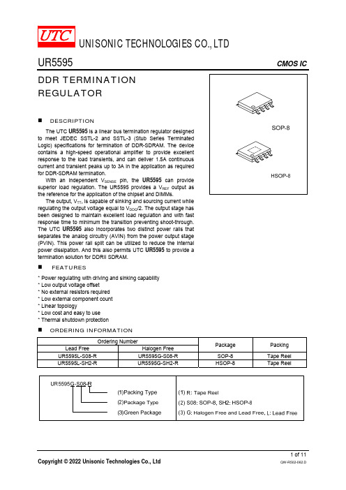
NC 1 GND 2 VSENSE 3 VREF 4
GND
8 VTT 7 PVIN 6 AVIN 5 VDDQ
SOP-8
HSOP-8
PIN DESCRIPTION
PIN NO
SOP-8
HSOP-8
1
1
2
2
3
3
4
4
5
5
6
6
7
7
8
8
-
Exposed Pad
PIN NAME
NC GND VSENSE VREF VDDQ AVIN PVIN VTT GND
TSHDN THYS
MIN 1.135 1.235 1.335 1.125 1.225 1.325 1.125 1.225 1.325
-20 -25 -25
TYP 1.158 1.258 1.358 1.159 1.259 1.359 1.159 1.259 1.359
0 0 0 320 13 2.5 100 165 10
VSENSE
The sense pin supply improved remote load regulation; if remote load regulation is not used then the VSENSE pin must still be connected to VTT. A long trace will cause a significant IR drop resulting in a termination voltage lower at one end of the bus than the other. Connect VSENSE pin to the middle of the bus to provide a better distribution across the entire termination bus can reduce the IR drop.
ruckus zf 7321

point in the market.Unlike other APs in its class, ZoneFlex 7321 supports transmit beamforming (TxBF) to increase in signal gain of up to 3 dB. In an ultra sleek, unobtrusive and lightweight form factor (7 oz. / 198 g.), the ZoneFlex 7321 supports up to 256 concurrent clients and can be deployed as a standalone wireless router in single AP environments such as a small business, remote office, or hotspot locations, or part of a centrally managed Ruckus Smart WLAN. The ZoneFlex 7321 comes with a myriad of advanced features that maximizes Wi-Fi performance and capacity includingbandsteering, airtime fairness, and capacity-driven auto channel Smart Dual-Band Selectable 802.11n Access PointBENEFITSreliability and performanceAdvanced feature set maximizes performance/capacityIntegrated bandsteering, airtime fairness, and capacity-driven channel selection minimizes interference and maximizes capacityUnobtrusive lightweight design for fast and easy installationCeiling, wall or desktop mountable with integrated mounting features for easy deployment anywhereBest in class channel selection with ChannelFly ™Capacity-driven channel selection predicts and automatically selects best performing channels based on statistical, real-time capacity analysis of all RF channelsFlexible deployment optionsZoneFlex ™7321As part of a centrally controlled wireless LAN, the ZoneFlex 7321 is managed through an highly intuitive and simply to use graphical, point-and-click Web interface. The dashboard (below) gives administrators a single and comprehensive view of the state of the wireless LAN.Best price/performance of any entry-level APThe ZoneFlex 7321 offers the industry’s best price/performance of any 2x2:2 entry-level AP in its class, making it ideal for single AP deployments, SMB requirements and emerging countries where high-capacity/value are essential.ChannelFly for optimal wireless performanceThe ZoneFlex 7321 uniquely supports an innovative approach to automatic channel selection called ChannelFly. A capacity-driven approach to auto channel selection based on observed channel traffic, ChannelFly uses statistic modeling to learn and select the best performing RF channel. It relies on actual capacity on all channels across both 2.4 and 5 GHz frequencies to automatically move clients (using 802.11h) to a better channel with less interference and more capacity.Simplified user security with Dynamic PSKWith the ZoneDirector, the ZoneFlex 7321 radically simplifies Wi-Fi security for users and IT administrators through the use of Dynamic Pre-Shared Keys. Once users successfully authen-ticate, a unique pre-shared encryption key is generated and automatically installed on the user’s device — along with the requisite SSID. This eliminates the tedious configuration of wireless settings and eases the burden of installing the same PSK (that could be easily compromised) on every user device.Differentiated services with multiple SSIDsUp to 8 discrete SSIDs are supported within the RuckusZoneFlex 7321, each with unique broadcast, QoS, security and management parameters. Up to 2,048 discrete WLANs can be created and mapped to the same or different AP or VLAN. This lets hot-zone operators easily offer tiered services to different users or traffic types. Enterprises can use this feature to dif-ferentiate guest, contractor and employee access policies or to segment different traffic types.Advanced WLAN applications with Smart/OSWith the Ruckus ZoneDirector Smart WLAN controller, the ZoneFlex 7321 supports a wide range of value-added appli-cations such as guest networking, Smart Wireless Meshing, Dynamic PSK, hotspot authentication, wireless intrusion preven-tion and many more. WLANs can be grouped and shared by specific APs. In a centrally managed configuration, the ZoneFlex 7321 works with a variety of authentication servers such as AD, LDAP , and RADIUS.High performance hot spotsThe 7321 uniquely supports the WISPr protocol to provide uni-versal authentication method or UAM (browser-based login at a captive portal), walled garden, time-based user session control,and additional RADIUS attributes for hotspot service settings.FEATURES• Transmit beamforming for extended range • Single radio with selectable 2.4 GHz or 5 GHz option for maximum flexibility *when used with Ruckus ZoneDirector controllerDC power10/100/1000PoE EthernetRelease mechanismprotected with security screw Integrated key holes for wall or ceiling mountKensington LockSoft reset Integrated T-bar mount1”192 gm. (7 oz.)Hidden cablesSpecificationsRuckus Wireless, Inc.880 West Maude Avenue, Suite 101, Sunnyvale, CA 94085 USA (650) 265-4200 Ph \ (408) 738-2065 FxCopyright ©2012, Ruckus Wireless, Inc. All rights reserved. Ruckus Wireless and Ruckus Wireless design are registered in the U.S. Patent and Trademark Office. Ruckus Wireless, the Ruckus Wireless logo, BeamFlex, ZoneFlex, MediaFlex, FlexMaster, ZoneDirector, SpeedFlex, Smart-Cast, and Dynamic PSK are trademarks of Ruckus Wireless, Inc. in the United States and other countries. All other trademarks mentioned in this document or website are the property of their respective owners. 801-70702-001 rev 01w w w.r u c k u s w i r e l e s s.c omPERFORMANCE AND CAPACITY TARGET UDP THROUGHPUT• 2.4 GHz, 110 MbpsSUPPORTED DATA RATES • 54,48,36,24,18,12,11,9,6,5.5,2,1 Mbps • 802.11n data rates AUTO CHANNEL SELECTION • SupportedRF POWER OUTPUT• Max transmit power 23 dBm (2.4 GHz); 21 dBm (5.0 GHz)• Country-specific power settings are configurable TRANSMIT POWER CONTROL • Supported BSSID • Up to eight POWER SAVE • SupportedWIRELESS SECURITY• WEP, WPA-PSK, WPA-TKIP, WPA2 AES, 802.11i• Authentication via 802.1X with the Zone-Director, local authentication database, support for RADIUS and ActiveDirectoryWIRELESS SECURITY• WEP, WPA-PSK, WPA-TKIP, WPA2 AES, 802.11i• Authentication via 802.1X, localauthentication database, support for RADIUS, LDAP, and ActiveDirectory CERTIFICATIONS• U.S., Europe, Australia, Brazil, Canada, Colombia, Hong Kong, India, Israel, Malaysia, Mexico, New Zealand, Philippines, Singapore, Taiwan, Thailand, Vietnam• WEEE/RoHS compliance • EN 60601-1-2• Wi-Fi Alliance Certification (Wi-Fi Certified ™)PLEASE NOTE: When ordering ZoneFlex Indoor APs, you must specify the destination region by indicating -US, -IL, or -WW instead of XX. When ordering PoE injectors or power supplies, you must specify the destination region by indicating -US, -EU, -AU, -BR, -CN, -IN, -JP, -KR, -SA, -UK, or -UN instead of -XX.Product Ordering Information。
Microsemi低功耗SmartFusion2 SoC FPGA开发方案

Microsemi低功耗SmartFusion2 SoC FPGA开发方案佚名
【期刊名称】《世界电子元器件》
【年(卷),期】2018(000)002
【摘要】Microsemi公司的SmartFusion2 SoC FPGA是低功耗FPGA器件,集成了第四代基于闪存FPGA架构,166MHz ARM Cortex-M3处理器和高性能通信接口,是业界最低功耗,最可靠和最高安全的可编逻辑解决方案.高速串行接口包括PCIe,10Gbps附加单元接口(XAUI)/XGMII)以及Ser Des通信,主要用在数据安全,马达控制,系统管
【总页数】6页(P37-42)
【正文语种】中文
【中图分类】TN791
【相关文献】
1.美高森美携手Solectrix 推出基于SmartFusion2 SoC FPGA的系统级模块 [J],
2.Microsemi推出下一代SmartFusion2 SoC FPGA [J],
3.基于SmartFusion2 SoC FPGA芯片的运动控制卡设计 [J], 张天佑;李全英
4.Microsemi SmartFusion2 SoC FPGA系列安全评估方案 [J],
5.美高森美SmartFusion2 SoC FPGA和IGLOO2 FPGA获得PCI Express 2.0 SIG认证 [J],
因版权原因,仅展示原文概要,查看原文内容请购买。
- 1、下载文档前请自行甄别文档内容的完整性,平台不提供额外的编辑、内容补充、找答案等附加服务。
- 2、"仅部分预览"的文档,不可在线预览部分如存在完整性等问题,可反馈申请退款(可完整预览的文档不适用该条件!)。
- 3、如文档侵犯您的权益,请联系客服反馈,我们会尽快为您处理(人工客服工作时间:9:00-18:30)。
元器件交易网Technical Data Sheet 5.0mm Round Type LED Lamps333-2USOC/H3/S400-A6█ Features :● ● ● ● ●Choice of various viewing angles Available on tape and reel. Reliable and robust Pb free The product itself will remain within RoHS compliant version.█ Descriptions :●The series is specially designed for applications requiring higher brightness●The led lamps are available with different colors, intensities.█ Applications :● ● ● ●TV set Monitor Telephone ComputerPART NO.333-2USOC/H3/S400-A6MaterialAlGaInPEmitted ColorSuper Sunset OrangeLens ColorWater ClearEVERLIGHT ELECTRONICS CO.,LTD. Device Number : CDLE-033-1546http : // Prepared date: 2005/9/21Rev.:1Page: 1 of 6 HongXia ZhengPrepared by:元器件交易网Technical Data Sheet 5.0mm Round Type LED Lamps333-2USOC/H3/S400-A6Package DimensionsNotes: 1. All dimensions are in millimetres2. The height of flange must be less than 1.5mm(0.059"). 3. Without special declared,the tolerance is ±0.25mm.█ Absolute Maximum Ratings at Ta = 25℃Parameter Forward Current Operating Temperature Storage Temperature Soldering Temperature Electrostatic Discharge Power Dissipation Reverse Voltage Symbol IF Topr Tstg Tsol ESD Pd VR Rating 50 -40 to +85 -40 to +100 260 ± 5 2000 120 5 Unit mA ℃ ℃ ℃ V mW VNote: *1:Soldering time ≦ 5 seconds.EVERLIGHT ELECTRONICS CO.,LTD. Device Number : CDLE-033-1546http : // Prepared date: 2005/9/21Rev.:1Page: 2 of 6 HongXia ZhengPrepared by:元器件交易网Technical Data Sheet 5.0mm Round Type LED Lamps333-2USOC/H3/S400-A6Electro-Optical Characteristics (Ta=25℃)Parameter Forward Voltage Reverse Current Luminous Intensity Viewing Angle Peak Wavelength Dominant Wavelength Spectrum Radiation Bandwidth Symbol VF IR Iv 2θ1/2 λp λd △λ Condition IF= VR= IF= IF= IF= IF= IF= 20 5 20 20 20 20 20 mA V mA mA mA mA mA Min. 2.0 / 1600 / / / / Typ. / / 2500 15 621 615 18 Max. 2.4 10 / / / / / Unit V μA mcd deg nm nm nmEVERLIGHT ELECTRONICS CO.,LTD. Device Number : CDLE-033-1546http : // Prepared date: 2005/9/21Rev.:1Page: 3 of 6 HongXia ZhengPrepared by:元器件交易网Technical Data Sheet 5.0mm Round Type LED Lamps333-2USOC/H3/S400-A6█Typical Electro-Optical Characteristic Curves:EVERLIGHT ELECTRONICS CO.,LTD. Device Number : CDLE-033-1546http : // Prepared date: 2005/9/21Rev.: Prepared by:1Page: 4 of 6 HongXia Zheng元器件交易网Technical Data Sheet 5.0mm Round Type LED Lamps333-2USOC/H3/S400-A6█Reliability test items and conditions:The reliability of products shall be satisfied with items listed below. Confidence level:97% LTPD:3%NOItemTest ConditionsTest Hours/Cycle 10 SECSample Size 76 PCSFailure Judgment CriteriaAc/Re1Solder HeatTEMP : 260℃ ± 5 ℃ H : +100℃ 15min ∫ 5 min L : -40℃ 15min H : +100℃ 5min ∫ 10 sec L : -10℃ 5min TEMP : 100℃0/12Temperature Cycle300 CYCLES76 PCS0/13Thermal Shock High Temperature Storage Low Temperature Storage DC Operating Life High Temperature / High Humidity300 CYCLES76 PCS41000 HRSIv≦Ivt*0.5 or Vf≧U 76 PCS or Vf≦L 76 PCS0/10/15TEMP : -40℃ TEMP : 25℃ IF = 20mA 85℃ / 85% RH1000 HRS0/16 71000 HRS 1000 HRS76 PCS 76 PCS0/1 0/1Note:Ivt:To test Iv value of the chip before the reliablility test Iv:The test value of the chip that has completed the reliablility test U:Upper Specification Limit L: Lower Specification LimitEVERLIGHT ELECTRONICS CO.,LTD. Device Number : CDLE-033-1546http : // Prepared date: 2005/9/21Rev.:1Page: 5 of 6 HongXia ZhengPrepared by:元器件交易网Technical Data Sheet 5.0mm Round Type LED Lamps 333-2USOC/H3/S400-A6Packing Quantity Specification1.500PCS/1Bag,5Bags/1Box 2.10Boxes/1CartonLabel Form SpecificationCPN: Customer's Production Number P/N : Production Number QTY: Packing Quantity CAT: Ranks 333-2USOC/H3/S400-A6 HUE: Dominant Wavelength REF: Reference LOT No: Lot Number MADE IN TAIWAN: Production PlaceNotes 1. Above specification may be changed without notice. EVERLIGHT will reserve authority on material change for above specification. 2. When using this product, please observe the absolute maximum ratings and the instructions for using outlined in these specification sheets. EVERLIGHT assumes no responsibility for any damage resulting from use of the product which does not comply with the absolute maximum ratings and the instructions included in these specification sheets. 3. These specification sheets include materials protected under copyright of EVERLIGHT corporation Please don't reproduce or cause anyone to reproduce them without EVERLIGHT'sconsent.EVERLIGHT ELECTRONICS CO., LTD. Office: No 25, Lane 76, Sec 3, Chung Yang Rd, Tucheng, Taipei 236, Taiwan, R.O.C Tel: 886-2-2267-2000, 2267-9936 Fax: 886-2267-6244, 2267-6189, 2267-6306 http:\\EVERLIGHT ELECTRONICS CO.,LTD. Device Number : CDLE-033-1546http : // Prepared date: 2005/9/21Rev.: 1 Prepared by:Page: 6 of 6 HongXia Zheng。
