NAND-Flash-Roadmap-2014
东芝29JH7UC高清

–7–
设计模式
1 . 进入设计模式 1) 29JH7UC、29JK7UC、34JH7UC 的设计模式同维修模式相同,在维护模式内,按遥控器的 MENU 键 3 次出现的 ADDR 000 DATA C8 WRITE OK 可以选择相应的地址,可以将地址内的数据更改。 2)选择调整项目 使用遥控器或者电视机本体的频道 UP/DN 键选择地址项、数据项、写入确认项。 3)调整数据 按遥控器上的 VOL 或本体的 VOL +/- 键可以更改数据。
–6–
3 . 维修模式中的功能说明 1) 各种信号下的数据是分段控制的 偏向数据分为: PAL 50\60\75\100 可选择扫描模式 NTSC 60 默认扫描模式 480P 信号 1080i/50 信号 1080i/60 信号 如果更换数字板这些信号的线性需要全部重新调整。 2) 数据的选择、调整 用遥控器或者本体的按键的频道升、降键 进行各个项目的选择。 用遥控器或者本体的按键的音量 +/- 键 进行各个项目的选择的。 注意: 以上各选项正常情况下不要调整更换记忆元后(拷贝完数据)后需要进行调整。
4 3 6
–4–
5
Xv 4
4 4
Xv
4
6
4
*
• 27
A
D D A B C
A
D
B
E
E F
B
E
C S N
23 948 274 TC-S
F
*
C
23 948 464
ห้องสมุดไป่ตู้
F N S
YHC
YH
YV YHC
YV YV
G G H
H
–5–
维修资料
1 . 进入维修模式 1)按一次遥控器上“消音”键 2)再次按“消音”键 3)按遥控器的“消音”键的 同时按本体的“MENU”
DRAM与NAND存储器总览,和10年内发展趋势

DRAM与NAND存储器总览,和10年内发展趋势这段时间,存储器市场受关注程度高涨。
不仅是因为知名分析机构近期都相继给出存储器产品的市场数据(以及有深圳昇维旭“加入DRAM玩家群”这类新闻),还在于存储器甚至开始应用于AI计算——很快我们将发布一篇文章,相对深入地剖析存内计算(in-memory computing)技术。
就半导体市场来看,存储器行业晃一晃,整个半导体市场就要跟着颤三颤。
所以我们在Gartner的半导体市场预测报告里就看到,全行业趋势预测有包含存储器和不包含存储器两份数据,就是因为存储器在半导体行业中的价值之大。
此前我们撰写过一篇,是对中科院刘明院士的主题演讲总结。
最近TechInsights也发布了一篇题为2022 and Beyond for Memory Technology的技术资料,大致总结了当前DRAM、NAND 存储技术的现状、发展趋势和挑战——这也算是他们的周期性更新报告项目了;对当代存储技术在商业市场的应用有更全方位的解析。
我们借此从技术层面来看看如今的存储技术发展到了何种程度,期望可作为爱好者或从业人员技术细节深挖的概览。
存储器在发展上,和逻辑器件还是有很大差别,但这一领域你来我往的技术竞争也相当激烈,上至数据中心服务器,下到各类嵌入式设备。
AIoT智能物联网终端对于存储器的需求未来也将是海量的。
2022年6月29日,全球领先的专业电子机构媒体AspenCore将与深圳市新一代信息通信产业集群联合主办【2022国际AIoT生态发展大会】,同期将举办工业互联网、智慧家庭、智慧机器人、智慧可穿戴、智慧两轮车等多场分论坛,多家企业将在论坛现场探讨AIOT领域的前景机遇。
【扫描二维码报名】现场与行业资深人士交流与互动!点击这里了解大会详情。
DRAM单元还在变小,虽然幅度没那么大了DRAM市场的几大参与者包括了三星、美光、SK海力士(SK Hynix),另外再加上南亚科技(Nanya)、力积电(PSMC)和长鑫存储(CXMT)等。
几种Nand flash文件系统的对比

几种Nand flas文件系统的对比来源:NLE-FFS: A Flash File System with PRAM for Non-linear EditingFor thesedevices, NAND flash memory has became the most attractive storage medium due to outstanding characteristics such as its increased capacity, low power consumption, small size and light weight. For the efficient management of NAND flashmemory, several flash file systems have been proposed, including JFFS2, YAFFS2, CFFS and PFFS. several file systems such as MNFS,NAMU and ScaleFFS have been designed forreal-time recording /playback and large-capacity storage. A. YAFFS2YAFFS2 is the most widely employed file system for NAND flash memory. YAFFS2 essentially saves the object ID (file ID) and the chunk (page) number in the spare region to show the offset of a page and the owner file of the page. Therefore, YAFFS2 reads the spare regions and object headers to establish the metadata in memory.Although YAFFS2 is designed to support NAND flash memory, it has scalability problems. With YAFFS2, the location of the updated page is saved in NAND flash pages or spare regions, as shown in Fig. 10 (a); hence, the file systemshould scan the entire flash space at the mounting time. Moreover, the entire directory and file system structures must be saved in main memory at that time. Thus, the mounting time and the memory usage are increased linearly according to the NAND flash size and the number of files.YAFFS2 has another problem in which many pages are consumed during metadata updates. The metadata are frequently updated and most of the metadata updates are performed in several bytes. Metadata updating creates large numbers of invalid pages. This severely degrades the write performance due to garbage collection, as byte-level updates and in-place updates are not allowed in NAND flash.B. PFFSTo address the problems with YAFFS2, PFFS wasproposed [4]. In PFFS, an architecture using PRAM and NAND flash memory is employed. In this file system,metadata are separated and stored in the PRAM region,whereas the other data are stored in the NAND flash memory region, as shown in Fig. 10 (b). Metadata separation has two advantages. First, the overhead of metadata updates is reduced. As shown in Fig. 10 (a),YAFFS2 writes 2KB of a NAND flash page for each metadata update. As the metadata are frequently updated and most of the metadataupdates are performed in several bytes, metadata updates with YAFFS2 create many invalid pages. This leads to severe performance degradation due to garbage collection. However, PFFS writes metadata in units of bytes, as it maintains metadata in the PRAM region as shown in Fig. 10 (b). Consequently, metadata separation by PFFS reduces the number of page-writes on account of in-place updating and byte-level updating. Second, PFFS requires only a short mounting time and uses a fixed amount of memory, whereas other flash file systems such as YAFFS2 require a considerable amount of time to scan NAND pages to construct in-memory file and directory structures.However, PFFS is also a general-purpose file system; thus,it does not sufficiently consider NLE operations. In this paper,to effectively support NLE, NLE-FFS is proposed. It is based on the architecture shown in Fig.3.。
韩国ATO公司产品介绍

To Be a World ClassTo Be a World Class Memory Solution ProviderSolution Provider MemoryMemory Solution Provider ATO Solution Co., LtdSolution Co., Ltd ATOJan 2013Jan2013About ATO Solution¾Efficient MCP Memory Solution ProviderSince established in 2007, ATO Solution has been growing as amemory MCP solution provider focusing on Digital Still Camera(DSC) application.ATO Solution has been recognized as one of the most reliable MCP memory f tTo Be The Best Partner For Your Memory Solutionmanufacturer.The 1Fab-less in NAND Flash memory industryFor Your Memory Solution ¾The 1st Fab-less in NAND Flash memory industry In 2012, ATO Solution successfully launched and started mass production for 256Mb, 512Mb SLC NAND Flash memory products, which were developed by its own design technology.ATO Solution expands SLC NAND product line-up by launching 1Gb SLC Flash memory within the Q1’2013.Corporate Core TechnologyThe effective NAND Flash Memory DesignP id d ffi i t M S l ti f t dOptimized NAND Flash Design &SPI Provided efficient Memory Solutions for customer needs Optimized NAND Flash Design & SPITo Be the Best Partner for Memory Solution To Be the Best Partner for Memory SolutionNAND/DRAM MCPNAND SPI(patented)Low Density NANDCompany OutlineOrganizationCEO Chris Park EstablishedOctober 31, 2007CEOHeadquarter705 Loadland EZ Tower, 153 Gumi-dong, Bundang-gu, Seongnam-si, Gyeonggi-do, Korea AdvisorV. Presidenty gg ,Product NAND FlashMCP (NAND+DRAM)13M USD R&D ProductionSupport Sales & Marketing Financial Account QualityCapital 1.3M USD Employees 41peoples Design Prod. Eng’rQuality Management Production Management PurchasingKorea Taiwan ChinaHR IRRevenue 24.3M USD (2012)Web Site2013Mass production start for own 1Gb SLC NAND Flash in Q1Mass production start for own 256Mb/512Mb SLC NAND Flash2012Started consumer MCP delivery for Altek /PentaxStarted own SLC NAND Flash delivery for Ability / Fuji-film 2009~2011Start consumer MCP delivery for SDIC (Samsung Digital Imaging Co.) Mobile MCP registered on Spreadtrum 2G/3G platforms New business started with Asia Optical Flextronics Selected as “Company with Good technology”by Korean Government New business started with Asia Optical Flextronics Development start for SLC NAND Flash (256Mb/512Mb)2008 Company EstablishedSelected as Company with Good technology by Korean Government Acquired ISO9001:2000, ISO14001:20042007Biz start with Foxconn , MCP for Digital Still CameraBusiness Milestone1.Early Positioning with Consumer MCP 2The 1Fab less for NAND Flash Memory2.The 1st Fab-less for NAND Flash Memory3.New innovative solution ; SPI NAND Flash MemoryPhase II ; Low Density NandPhase III ; Nand based SPIProvide NAND-cell based Phase I ; Market Solution Provided Memory Solution Low Density NAND Flash Memory Development & Marketing for Consumer & SPI Flash for PC, Mobile, and Consumer MarketProvided Memory Solution ; MCP for Consumer Marketg Mobile Market`2007`2008`2009`2010`2011`2012`2013`2014`2015Phase I ; MCP Solution for ConsumerPartners CustomersMARKETING /QUALITY SERVICETAM : ~150M set / yearPhase II ; Low Density NAND Flash9IDMs are focusing on high density NAND Flash Memory-Capacity and Technology drivenMarket still needs continuous high reliable product and serviceHigh Competition ply9Market still needs continuous high reliable product and serviceamong MajorSuppliers and/SupDemUnstable supply& Continuous demandSupplyATO Solution’sTarget Marketpp yDemandSuppliers Move256Mb512Mb1Gb2Gb4Gb Density8Gb16GbEdge in design competiveness¾Die Size Comparison TableP d tCDi Si (2)W/FR ti Product Company Die Size (mm2)Tech(nm)W/F Size Ratio 256Mb H35.82908” 2.7435828”274(1.8V/3.3V)M 35.82908 2.74S(EOL)37.449012” 2.86ATO Solution13.07578”1512Mb (1.8V/3.3V)H33.11578” 1.58S 38.476312” 1.85T 29.634312” 1.42ATO Solution20.85578”11Gb (33V)H 30.994812” 1.093090109(3.3V)For 1bit ECCP 30.975012” 1.09ATO Solution28.22578”1Market Outlook _ WW SLC NAND Flash FCST (Consumer)K unit500,000 600,000 128Mb256Mb 512Mb 1Gb 2Gb 4Gb 8Gb200,000 300,000 400,000 Source : Forward Insight (2012. Sep)-100,00020112012201320142015 2016Total Consumer Demand byDensity (kUnits)2011 2012 2013 2014 2015 2016 CAGR<128Mb ------128Mb 6,119 5,074 4,089 2,144 --44145315301900152591925256Mb 44,145 31,530 19,001 5,259 1,925 -512Mb 114,519 96,382 75,177 59,212 47,661 30,157 -23.4%1Gb 147,898 154,362 161,864 167,566 179,001 187,513 4.9%2Gb 109,268 104,836 107,999 112,413 119,733 130,192 3.6%4Gb 54,644 54,906 61,917 73,858 85,309 95,797 11.9%757910037145912164430677411528Gb7,579 10,037 14,591 21,644 30,677 41,152Total (128Mb-8Gb)484,173 457,127 444,637 442,096 464,306 484,812 0.0%¾Global SLC NAND FCST in digital consumer market is estimated as a quite flat.Market Outlook _ WW Mobile Phone FCST2500Smartphone Mid-End Feature Phone Low-End Feature Phone206%1500200025.9%22.3%15.2%23.3%10.2%21.9% 6.7%20.6%358%24.7%26.1%0500100051.7%61.5%67.9%72.7%39.5%35.8%29.5%44.4%2011 2012 2013 2014 2015 2016Source : Forward Insight (2012. Sep)Mobile phone unit forecast (M Units)2,0 11 2,012 2,013 2,014 2,015 2,016 CAGRS t h 471658901112713551566272%Smartphone 471 658 901 1,127 1,355 1,566 27.2%Mid-End Feature Phone 710 596 452 278 203 144 -27.3%Low-End Feature Phone 418 411 389 427 437 444 1.2%¾Global total mobile phone unit shipments will reach to 1.7 billion units in 2013.¾Feature phone have the larger share in 2012 mobile market but its trend is expected to change after 2013Mobile Phones Units 1,599 1,665 1,742 1,832 1,995 2,154 6.1%when smart-phone will take over it.Brief Specification _ 256Mb / 512Mb / 1GbFEATURES DESCRIPTIONDensity 256Mb 512Mb 1GbArchitecture Single-Level CellPower Supply 1.8V: 1.7V ~ 1.95V / 3.3V: 2.7V ~ 3.6V 3.3V: 2.7V ~ 3.6VMemory Cell Array x8 : (32M + 1024K) x 8bits x16 : (16M + 512K) x 16bits x8 : (64M + 2M) x 8bitsX16 : (32M + 1M) x 16bits x8 : (128M + 4M) x 8bitsPage Size x8:(512 + 16)Bytes / x16:(256 + 8)Words x8:(2K + 64)BytesRandom Access 15us(1.8V) / 12us(3.3V)25usSerial Page Access 50ns(1.8V) / 30ns(3.3V)25nsProgram / Block EraseTime 200us(Typ) / 2ms(Typ)Copy Back ProgramOperation Fast Page copy without external bufferingOTP area 16Kbytes/8K words(32 pages)16Kbytes(8 pages)Hardware Data Protection Program / Erase locked during Power transitionsEndurance /Data100K P /E C l ith 1bit ECC /10Endurance / Data Retention 100K Program / Erase Cycles with 1bit ECC / 10years Temperature Range 0℃to +70℃/ -40℃to +85℃P k I f ti 48P TSOP (1220)/48B fBGA (99)48P TSOP (12x20mm)fBGA (9x9mm)Package Information 48P TSOP (12x20mm)/ 48B fBGA (9x9mm)48B fBGA (9x9mm)48B fBGA (6.5x8mm)Phase III ; SPI NAND Flash1Gb (SPI, Quad IO), 3.3V, 104Mhz(133Mhz@15pF), 8x6 WSON -Very high reliability,competitive cost,simpler package form factorHigh VoltageHOLD#Very high reliability, competitive cost, simpler package form factorControl Logic GeneratorI/O Shift RegisterW#CS#SCLKSISOECCGeneratorSPI InterfaceAddress Registerand Counter2K Bytes Data Buffer StatusRegister7FFFFFFh7FE0000hEmbedded ECCX DecoderEmbedded ECCY Decoder0000000h001FFFFhNAND Cell ArraySLC NAND Flash Product Roadmap 20132014ES CS MP Q1Q2Q3Q4Q1Q2Q3Q41.8V/3.3V256Mb 32Mx8 / 16Mx16Small Block TSOP/BGA/MCP1.8V / 3.3V512Mb 1.8V/3.3V64Mx8 / 32Mx16Small Block TSOP/BGA/MCP1.8V / 3.3V1Gb 3.3V128Mx8Large Block 3.3VTSOP/BGA/MCPNOTE) Endurance(256Mb/512Mb/1Gb) : 100K Program/Erase Cycles (with 1bit/528byte ECC)SLC NAND Flash Product Roadmap –cont’20132014ES CS MPQ1Q2Q3Q4Q1Q2Q3Q42Gb 1.8V/3.3V 256Mx8 / 128Mx16Large Block TBDLarge Block4Gb 1.8V/3.3V 512Mx8 / 256Mx16Large Block TBDNOTE) Endurance(2Gb/4Gb) : 100K Program/Erase Cycles (with 4bit/528byte ECC)Serial NAND Flash Product Roadmap20132014 ES CS MPQ1Q2Q3Q4Q1Q2Q3Q4 33V1Gb3.3V(128M+4M)x Bytes104MHzInternal ECC codeti3.3VgenerationWSON/SOP104MHzInternal ECC code2Gb/4GbgenerationTBD NOTE) Endurance : 100K Program/Erase CyclesCertificationsISO9001 : 2008• Oct 02, 2008 Acquired ISO9001ISO14001 : 2004• Oct 02, 2008 Acquired ISO14001Eco-Partner• Feb 09, 2009 Acquired Eco-Partner Di i i C tifi t N R i t ti D t E i d D t SDivision Certificate No.Registration Date Expired Date Sponsor ISO9001: 2008QI8221/082008.102013.11ICRISO14001:2004EI3363/082008.102013.11ICREco-Partner EPC-52452009.02-SAMSUNGco a t e C55009.0S SU GSummary ; Core Competencies Leading edge NAND Memory technology •High level of NAND Flash design experience and capability for optimized architecture D i d D l t C bilit fk ith li bl lit•Design and Development Capability of new packages with reliable quality •Market leading test technology, which is core factor of MCP quality•Stable quality control through field-proven management systemS l ti h ld i t d d li d IP f d Strategic relationship with Supply-ChainStable support with Strategic relationshipATO Solution holds 6registered and 6applied IPs for NAND and NAND SPI •Stable support with Strategic relationship Optimized operation and organization focusing on customer service•Simplified and optimized operation and logistics, which are result in reasonable lead time and customer service Memory specialized human resources•Key Engineering Resources are all from Major Memory Companies with 11+ years experience-Memory : Hynix, Samsung, STMicroelectronics(Numonyx), SMIC-Packaging : Stats ChipPAC, Amkor, Winpac-Test : iTEST, HisemFlexible and dynamic customer service•Customer Specific design and technical solutionThank you for your attention. Thank you for your attentionKOREA(HQ)CHINATAIWAN。
3Q 10 DRAM Roadmap Rev_0_final

64Mb
O-die TSOP2
128Mb
• x16, 56nm • 400Mbps
O-die, x16, 56nm 2.5V 400Mbps
N-die TSOP2
256Mb
• x4/x8/16, 56nm • 400/333Mbps
N-die, x4/8/16, 56nm 2.5V 400/333Mbps J-die, x4/8/16, 46nm 2.5V 400/333Mbps
8/10
gDDR2/3 Roadmap
VDD E/S C/S
year Density
SAMSUNG SECRET
M/P
July, 2010
2010 Current Generation 1Q
E-die
• x16, 56nm • 1.0/0.8Gbps
2011 3Q 4Q 1Q 2Q 3Q 4Q
2Q
6/10
Consumer SDRAM Roadmap
VDD E/S C/S
year Density
SAMSUNG SECRET
M/P
July, 2010
2010 Current Generation 1Q
N-die TSOP2
• x8/16, 95nm • 166/133Mbps
2011 3Q 4Q 1Q 2Q 3Q 4Q
2Gb
• x4/8, 68nm • 800/667Mbps
EOL Announced for 2Gb A-die in Mar. ‘10
*PKG Size : 512Mb I-die & J-die / 1Gb Q-die, E-die & F-die : 7.5x9.5(60Ball,x4/8), 7.5x12.5(84Ball,x16) 2Gb A-die : 11x18(60+8Ball,x4/8) 8 ball : Support balls
TechInsights-DRAM Roadmap2014
DRAM Technology
As of Today: Micron/Nanya
Tech. Node Die Floor Plan Cell Architecture Key Technology 79nm/70nm/87nm (STI/WL/BL Pitch) 2Gb/Die (LPDDR2) 72 mm2/Die Area 0.0086 μm2/cell(6F2) W/TiN Buried WL Single W BL Single SiN MESH ZAZ HK Dielectrics 80nm/62nm/90nm (STI/WL/BL Pitch) 512Mb/Die (DDR3) 68 mm2/Die Area 0.0084 μm2/cell(6F2) W/TiN Buried WL Double W BL Double SiN MESH ZAZ HK Dielectrics
@1T/1C, 6F2
1 2 3
<Fin Structure>
<RCAT Structure>
<HK Dielectrics/Capacitor>
Content for re-use only with TechInsights permission.
DRAM Technology
Further Scaling Down: 1X, 1Y or 0X nm?
1T-DRAM (4F2)
DRAM Technology
DRAM Technology Roadmap
Content for re-use only with TechInsights permission.
ABOV MCU roadmap-2014
02
2KB
04
4KB
08
8KB
16
16KB
32
32KB
48
48KB
PKG type
B PDIP D SOP G SKDIP J MLF K SDIP
L LQFP
8 80
64
0 100 128 A 128 256
64KB Q
128KB R 256KB U
QFP
TSSOP QFN
* CEC (Consumer Electronics Control) ** DMA (Direct Memory Access) *** Supported IAP (In-circuit Application Programming) **** COMBI (Code flash + Data EEPROM)
SKDIP
J
MLF
K
SDIP
L
LQFP
Q
QFP
R
TSSOP
U
QFN
FN
DFN
05
Control your innovation drama
General purpose MCUs
8-bit MCUs
32-bit MCUs
Full flash MCUs Flash MCUs OTP MCUs ABC-M3 ABC-M0 ARM7
"#07̒导ᠧ༆䁑˙ࣩ̙ஷ过对产ۜٙ䕂dˏ导܄䔚创ிһ䅎ɽdһ౽ঐdһ节ঐdһЭϓ͉d һ࢙应ٙ͜产ۜf
Solution for customer satisfaction
Microcontrollers
MDS tool
Reference board
华为视频会议解决方案
华为高清视讯系统技术方案建议书临时方案华为技术有限公司2016年10月9日使用说明(2016.10.9):1、模板使用时根据实际客户需求和方案设计,选择相应章节内容,与实际方案不相关的内容需删除;2、模板中使用说明、备注部分为内部参考,具体制作面向客户提交的方案时,需删除所有使用说明、备注部分。
目录1视讯技术发展及应用需求 (5)1.1技术发展 (5)1.1.1视频 (5)1.1.2音频 (5)1.1.3组网 (5)1.2应用需求 (6)1.2.1高临场感体验 (6)1.2.2低带宽高清 (6)1.2.3良好的网络适应性 (6)1.2.4良好的易用性 (6)1.2.5稳定性和可维护性 (7)1.2.6标准开放和融合互通 (7)1.2.7支持多种线路接入方式 (7)1.2.8客户化、可定制 (7)2华为高清视讯系统需求分析 (7)2.1华为背景简介 (7)2.2华为网络现状分析 (8)2.3华为客户需求分析 (8)3 华为高清视频系统设计方案建议 (8)3.1系统设计依据 (8)3.2系统设计原则 (11)3.3方案四SMC2.0+MCU96X0 ................................................................... 错误!未定义书签。
3.4系统组网方案四配置清单 ...................................................................... 错误!未定义书签。
4华为高清视频系统主要功能及特点 (12)4.1良好的高清晰音视频沟通体验 (12)4.1.1全高清108060端到端解决方案 (12)4.1.2高流畅性 (12)4.1.3强大全编全解处理能力,最大限度支持动态速率、协议适配 (13)4.1.4VME+H.264 HP 低带宽高清 (13)4.1.5H.264 SVC技术 (14)4.1.6高清1080P60FPS静态/动态双流 (14)4.1.7高保真,立体声,CD音质效果 (15)4.2丰富的会议召集模式 (15)4.2.1主叫呼集 (15)4.2.2匿名会议(电话会议模式) (16)4.2.3管理员调度 (16)4.2.4网络预约 (16)4.2.5视音频IVR导航与ad-hoc创建和加入会议 (16)4.2.6特服号入会 (16)4.2.7Outlook预约会议 (16)4.2.8云化资源池管理实现会议智能调度 (16)4.3良好的网络适应性 (18)4.3.1超强纠错(SEC 2.0-- Super Error Concealment) (18)4.3.2超强纠错(SEC 3.0-- Super Error Concealment) (18)4.3.3智能调速(IRC--Intelligent Rate Control) (19)4.3.4断线恢复(RoD--Reconnect on Disconnect) (19)4.3.5丢包重传(ARQ--Automatic Repeat reQuest) (20)4.4简单易用 (20)4.4.1用户界面简约时尚 (20)4.4.2PAD智能操控平台 (20)4.4.3丰富的会议控制功能 (20)4.4.4会议模板预置功能 (21)4.4.5字幕与横幅功能 (22)4.4.6一屏三显,节约投资 (22)4.4.7多视一流功能 (22)4.4.8无线辅流,轻松共享数据 (23)4.4.9支持WIFI呼叫及无线麦克 (23)4.4.10USB零配置 (24)4.4.11全景会场功能 (25)4.4.12多组多画面(on-table多画面) (25)4.4.13图形化操作界面 (25)4.4.14软终端随时随地接入会议 (26)4.4.153G-SDI接口实现1080P60fps远距离传输 (28)4.5安全稳定 (28)4.5.1产品成熟 (28)4.5.2系统稳定 (29)4.5.3多重加密 (30)4.5.4系统安全 (30)4.5.5资源池会议备份 (32)4.6管理维护方便 (33)4.6.1分级分权,大网维护简单 (33)4.6.2Nlog网络线路实时监控 (37)4.6.3支持WEB管理 (37)4.6.4系统设备拓扑图生成管理 (37)4.6.5系统设备配置批量升级及备份 (37)4.6.6系统告警和日志管理 (38)4.7标准互通 (39)4.7.1采用国际标准协议 (39)4.7.2支持TIP协议,与思科网真互通 (39)4.7.3华为视讯产品互联互通能力介绍 (39)4.7.4支持与微软UC系统互通 (41)4.7.5端到端IMS融合解决方案 (42)4.8丰富组网 (42)4.8.1支持多种接入方式 (42)4.8.2最大5级和超强多通道级联能力 (43)4.8.3支持大容量语音接入,满足在外人员接入视频会议需求 (43)4.8.4支持高清录制点播功能 (44)4.8.5支持软件化部署的管理平台 (48)4.8.6完善的公私网穿越解决方案 (49)4.9专业定制 .................................................................................................. 错误!未定义书签。
SAS卡发展趋势分析

已淘汰 正在使用中 引入阶段 样品阶段
研发阶段
LSI HBA卡发展趋势
11
二、Raid卡发展趋势
PCIE3.0 x8的6G raid卡或HBA卡接口能提供多大的带宽呢? PCIE1.0总线的速率为2.5GT/s,PCIE2.0则达到了5GT/s,PCIE3.0将再次加倍达到 8GT/s,数据经编码传输保证数据传输密度和直流平衡,于是PCIE 3代里面采用了 扰码的方法,以确保接收机时钟电路对进入数据流的锁定,即数据传输前先和一个 多项式进行异或,这样传输链路上的数据就看起来比较有随机性,到了接收端再用 相同的多项式把数据恢复出来。通过上述方法,PCIE 3代可以用8GT/s的传输速率 实现比2代的5GT/s高1倍的数据传输速率
Raid卡 SAS接口速率 主处理器ROC 处理器核心数 处理器频率 缓存大小 内存频率 PCIE接口速率 Raid支持 性能iops 功耗 接口方式 缓存备份策略 (电池/电容) 8708EM2 3Gb/s 1078 powerPC440 x1 500MHz 256M DDR2 667MHz 1.0a x8 0\1\10\5\50\60 300k 2Min-SAS x4 电池 9261-8I 6Gb/s 2108 powerPC440 x1 800MHz 512M DDR2 800MHz 2.0 x8 0\1\10\5\50\60 400k 2Min-SAS x4 电池 9266-8I 6Gb/s 2208 powerPC440 x2 800MHZ 1024M DDR3 1333MHz 2.0 x8 0\1\10\5\50\60 550k 2Min-SAS x4 电容/电池 9271-8I 6Gb/s 2208 powerPC440 x2 800MHZ 1024M DDR3 1333MHz 3.0 x8 0\1\10\5\50\60 550k 2Min-SAS x4 电容/电池 9361-8i 12Gb/s 3108 powerPC476 x2 1.2GHz 2048M DDR3 1866MHz 3.0 x8 0\1\10\5\50\60 1M 2HD Min-SAS x4 (SFF-8643) 电容/电池
3D NAND Flash Memory and Beyond

A World’s First Product ofThree-Dimensional Vertical NAND Flash Memory and BeyondKi-Tae Park, Dae-Seok Byeon and Doo-Hyun KimFlash Design Team, Memory BusinessSamsung Electronics Co. Ltd1-1, Samsungjeonja-ro, Hwaseong-si,Gyeonggi-do 445-330, South Koreakt21c.park@Abstract— In this work, we present a 3D 128Gb 2bit/cell vertical-NAND (V-NAND) Flash product. The use of barrier-engineered materials and gate all-around structure in the 3D V-NAND cell exhibits advantages over 1xnm planar NAND, such as small Vth shift due to small cell coupling and narrow natural Vth distribution. Also, a negative counter-pulse scheme realizes a tightly programmed cell distribution. In order to reduce the effect of a large WL coupling, a glitch-canceling discharge scheme and a pre-offset control scheme is implemented. Furthermore, an external high-voltage supply scheme along with the proper protection scheme for a high-voltage failure is used to achieve low power consumption. The chip accomplishes 50MB/s write throughput with 3K endurance for typical embedded applications. Also, extended endurance of 35K is achieved with 36MB/s of write throughput for data center and enterprise SSD applications. And 2nd generation of 3D V-NAND opens up a whole new world at SSD endurance, density and battery life for portables.Keywords-component; 3D Vertical NAND Flash; Gate stack; negative counter-pulse; WL crosstalk reduction, external high voltage supply; high performance; good endurance; solid-state drive; enterprise application;I.I NTRODUCTIONIn the past few years, various 3D NAND Flash memories have been demonstrated, from device feasibility to chip implementation, to overcome scaling challenges in conventional planar NAND Flash devices [1-3]. Fig. 1 shows the scaling trend of NAND Flash memory. According to the trend, the scaling down doesn’t seem to stop yet. However, a subsequent development of the next-generation planar NAND technology is now facing far more difficulties than ever. The difficulties in shrinking the NAND cell include increased manufacturing costs due to the use of quadruple patterning and the extreme ultraviolet lithography. In addition, complex air-gap technology is required for not only WLs but also cell actives [4]. Furthermore, sophisticated metal-gate process is also required [5]. As for the cell properties, a reduced number of programming electrons and increased cell-to-cell interference induce unprecedented challenges to overcome. These problems motivated the development of the next-generation node beyond 1z nm-class NAND Flash in 3D vertical NAND.Recently, new emerging NAND markets driven by smart-phones, tablet PCs and SSDs require much higher performance than ever [6]. The increasing demand for a higher performance gives additional challenges in NAND Flash manufacturing. Such requirement also drives the development of 3D NAND technology.In this work, we present the world first 128 Gb MLC V-NAND devices that is already in mass production. It took more than 10 years of research and development [8]. Also we announce the 32-WL stacked V-NAND using 3-bit per cell technology for the first time, and we realized solid state drive (SSD) solution for client application.One Terabit Density in 2017128Gb1Tb. . . . . . . . . . . .Year. . . . . . . .256Gb ?3D V-NAND2D Planar NANDFigure 1. Design rule(layer) roadmap of 3D V-NAND and 2D planar devicetechnology.Figure 2. Die micrograph of 128Gb 2bit/cell 3D V-NAND FlashII. C HIP A RCHITECTUREThis work presents an 128Gb 2 bit/cell NAND Flash device based on the first generation of the vertical NAND (V-NAND) cell array technology with damascened metal gate SONOS type cell [3]. Fig. 2 shows the die micrograph of the 3D V-NAND Flash. This chip has 24 stacked WL layers and consists of 2 planes each containing 64 Gb arrays (2732 of 3 MB blocks with 8 KB pages). We employed the shared-WL-block scheme for the row circuit [9] and the one-side page buffer for the column circuit [9-10] as in planar 2D NAND devices to reduce area. These organization helps obtain 133mm2 chip with 80% array efficiency and 0.96 Gb/mm2 which is the highest density ever reported.The V-NAND chip has 24 stacked WL layers and over 2.5 billion channel holes. This configuration can be seen in Fig. 3 which shows a simplified schematic diagram, an SEM image of the fabricated V-NAND array and a cross sectional diagram of a unit cell. In order to ensure high performance, damascened metal gate structure was adopted and as basic cell structure, gate all-around structure using advanced barrier engineering material in Charge Trap Flash (CTF) cell was used. As shown in the schematic diagram, 24 WL layers, 2 dummy word line (DWL) layers, and two string select gate layers constitute the 3D V-NAND string and a BL is shared by the eight V-NAND strings. Since there are 64K BLs, the size of a block is 3MB(8KBx8x2x24).3D V-NAND Era Begins20132432xInsulatorGate8Figure 3. Schematic diagram and cross-sectional view of 3D V-NAND array.Isolated channelNatural Vth Distribution 3DN o r m a l i z e d (a .u .)1x n 2DCell Coupling33% ↓84% ↓Vth (a.u)# o f C e l l s3D V-NAND1xnm NANDInitial VthAfter Coupling3D V-NAND 1xnm NAND(a) (b)Figure 4. Cell characteristic comparison (a) V-NAND cell structure and (b) narrow Vth variation and small cell to cell coupling.This architecture is similar to that of a planar NAND (except for the SSL decoders which selects a target SSL to operate). It is mainly because the 3D V-NAND, like a conventional planar device, is programmed and erased based on the FN tunneling mechanism. In particular, the bulk erase feature of this chip provides better characteristics such as higher erase speed, lower power and more reliability, compared to other V-NAND structure based on the hole generation by GIDL mechanism. So, conventional operations used in a planar NAND can also be applied to the 3D V-NAND with simple modifications. Therefore, a lot of experiences and know-how of the planar NAND design can be used. This is a very good advantage for developing this new device.In addition, the 3D V-NAND chip has the wave-pipeline data-path architecture which is used in the peripheral area of 1xnm planar NAND.[11] We have achieved 667Mbps performance through circuit optimization and improvement of pre-fetch size.III. V-NAND C ELL C HARACTERISTICSThe 3D V-NAND cell is based on the Charge Trap Flash technology in the advanced engineering and gate all-around structure [12]. Therefore, as shown in the Fig. 4(a), its channel area is bigger than that of a planar counterpart, due to its cylindrical geometric structure. As a result, basic cell characteristics of 3D V-NAND such as the natural Vth distribution and the cell-to-cell coupling are superior over those of a planar NAND. Fig. 4(b) shows the basic 3D V-NAND cell characteristics, compared to a planar 1xnm NAND. The natural Vth distribution is reduced by 33%, and the cell coupling characteristic is reduced by 84%. Such good cell characteristics directly lead to the excellent performance and high reliability of the V-NAND device, compared to a planar NAND.Negative VoltageVreadoffoffVreadHigh voltage potential by self-boosting effectVpgmVreadVrProgram @ (n) loopAccelerated Detrap (V-NAND)Reprogram @ (n+1) Loop RealizingNarrow Vth Distribution80% ↑C o n v e n t i o n a l C T F1x n 2DVth VariationI m p r o v e dThis Work (3D V-NAND)(a) (b)Figure 5. (a) Negative counter-pulse scheme and (b) Diagram of its mechanism and measured Vth Variation.IV. N OVEL S CHEMES FOR H IGH P ERFORMANCE AND L OWP OWER A.Negative Counter-Pulse SchemeIn Charge Trap Flash (CTF) devices, unlike in floating gate (FG) devices, a fast de-trapping of programmed electrons occurs during and after programming [13]. This phenomenon increases the programmed state’s Vth distribution, and thus it impairs the reliability of the programmed data.To overcome the problem, the negative counter pulse scheme is implemented. This scheme generates a counter-pulse by boosting the channel potential through the self-boosting mechanism while applying a negative gate voltage (see Fig. 5(a) for the illustration). The generated large negative field accelerates the de-trap process between program loops, thereby improving the programmed state’s Vth distribution (see Fig. 5(b) for the illustration). Since this operation is embedded in verify read operations, timing penalty for applying the scheme is small.B. WL Crosstalk Reduction SchemesIn the V-NAND architecture, a capacitive coupling between WLs is much larger than that in a planar NAND. This is because a WL in the 3D V-NAND is a plane, while that in a planar counterpart is a line. In this first generation 3D V-NAND, the coupling capacitance between WLs is about four times larger than that in a planar NAND. Because of this coupling, driving a WL can cause a large glitch in the neighboring WLs and results in an unintended disturbance. In order to resolve the problem, we propose two schemes in this work, a glitch-canceling discharge scheme and a pre-offset control scheme. In the first scheme, a coupling signal glitch is cancelled by a WL discharge circuitry as described in Fig. 6(a). Since core signals in NAND operate in a very predictable and deterministic way, such cancellation can be achieved by precise timing and amount control of the discharge circuitry. In the pre-offset control scheme, the amount of the coupling glitch is predicted based on the target voltage of the aggressor WL. Fig. 6(b) shows the worst case simulation result of the proposed schemes. The aggressor WL is the selected WL, while the victim WL is the adjacent unselected WLs. As shownin the figure, the coupling glitch is significantly reduced by using the proposed schemes, which in turn results in eliminating the disturbance cased by WL-to-WL crosstalk.C. External High-Voltage-Supply Scheme for SSDsThe proposed 3D V-NAND can endure 35K program-erase cycles, which is 10 times higher than a typical planar NAND can. Therefore, it is suitable for the applications such as high-end datacenters and enterprise SSDs. In addition, the V-NAND is suitable for the low power operation required by those applications. NAND power accounts for about 47% of the entire SSD power, and this portion increases with more way interleaving. Here, in order not to exceed the temperature limit even with the 8-way interleaving, an SSD is often configured to intentionally reduce its performance and the operation temperature. This is a scheme known as the dynamic throttling [14].In this work, we used the external high voltage available in the SSD board instead of the internal one generated from on-chip pumps to reduce the power without any sacrifice in performance (see Fig. 7(a)). When using the external high voltage, we implemented a level detector so that when the high voltage level is decreased below a threshold, it discharges internal nodes completely and safely. This operation protects the circuit from malfunctioning even with the unstable high voltage source or in the case of sudden power off. Fig. 7(b)shows the simulation result.(a)C o n v e n t i o n a lVpgm(Selected WL)Neighboring WLConventionalProposedTargetCrosstalkN o r m a l i z e d (a .u .)53% by Degeneration Sch.+ 43% by Coupling-Offset Sch.(b)Figure 6. WL Crosstalk Reduction Schemes (a) Bias and Block diagrams of a glitch-canceling discharge scheme and (b) Simulated waveform of WLsignal in 3D V-NAND array.Ext.HV (12V)On-chip PumpHigh VoltageLevel DetectorHigh VoltageSwitchVrefInternal NodeResetExt.HVResetVpgm(Selected WL)(a) (b)N o r m a l i z e d (a .u .)ICC1(Read)C o n v e n t i o n a lE x t .H VICC2(Program)43% ↓54% ↓53% ↓ICC3(Erase)(c)Figure 7. (a) External high-voltage-supply scheme, (b) its simulated waveform and (c) Measured active power dissipation using a proposedexternal high-voltage-supply schemeFig. 7(c) shows measured active power of the 3D V-NAND at each operation. Compared to the consumption without using the external high-voltage scheme, about 50% of the energy consumption is reduced. As a result, it is possible to use 8-way full interleaving operation without the throttling, thereby increasing the overall SSD performance.Vth (a.u)# o f C e l l s3D V-NAND after 35K cyclePlanar 1xnm NAND after 3K cycleN o r m a l i z e d (a .u .)Time [us]Avg. tPROG=0.45ms (36MB/s)Avg. tPROG=0.33ms(50MB/s)(a) (b)Figure 8. (a) Comparison of measured Vth distributions, and (b) measuredwrite speedFig. 8(a) shows 2-bit/cell Vth distribution of the 3D V-NAND after 35K program-erase cycles compared with that of a planar NAND after 3K cycles. Both NANDs are designed to have the same performance of 36MB/s write throughput. The 3D V-NAND has a very excellent MLC Vth distribution, compared to that of the 1xnm NAND, even with the 10 times more cycles. Since there is a trade-off between endurance and performance in NAND, the V-NAND can be configured to have 3K endurance and 50MB/s write throughput which is the fastest ever reported, as shown in Fig. 8(b). Note that 64Gb planar NANDs are used in the planar NAND SSD, while128Gb 3D V-NAND dies are used in the V-NAND SSD. As a result, the same number of NAND bus connected to system and half the number (way) of chip used to a single bus is used for the V-NAND SSD. Even though half number of chip causes performance degradation generally, superior performance characteristics can be overcome in all aspects penalty.This is a good example that shows the benefit of the 3D V-NAND and why we developed this technology. Table I.summarizes the feature of this V-NAND. Again, the device provides the best performance for various applications, 3K low endurance with 50MB/s ultra-high performance value for mobile application and 36MB/s high performance with 35K ultra-high endurance value for enterprise SSDs.TABLE I.M AIN F EATURES OF T HIS W ORKFeaturesBit per Cell2Density 128 GbTechnology 3D V-NAND, 3 metal layersOrganization8KB x 384 pages x 5464 blocks x 8 strings Program performance 50MB/s for embedded application36MB/s for enterprise SSD application Data interface speed667Mbps@Mono, 533Mbps@8-stack Power supplyVcc=3.3V / Vccq=1.8VV. N EXT G ENERATION OF V-NANDAs shown in Fig. 9, we announced the 32-WL stacked V-NAND using 3-bit per cell technology for the first time and we realized SSD solution for client application [15, 16]. This next generation V-NAND has many advantages such as 50% less power consumption by external pump source, 2x faster write speed than 1xnm planar NAND and 10x increased endurance characteristics than 1xnm planar NAND. This 32-WL 3-bit 3D V-NAND flash device realized 2nd generation and we will continue stacking more than 5 generations more. This technology can realize 3D V-NAND capacity breakthrough in flash solution. This next flash era is more suitable for low-cost and high performance NAND flash solution such as high-end mobile, datacenter, enterprise SSD applications.3bit Cell3bit Cell3bit Cell32-WL Stacked(a) (b)Figure 9. 128Gb 32 stack, 3-bit V-NAND (a) chip micrograph and (b) fabricated cell structure SEM image.VI.C ONCLUSIONSWe have realized 3D V-NAND Flash with 50MB/s write throughput with 3K endurance for a typical embedded application and 36MB/s write throughput with 35K endurance for data center and enterprise SSD applications for the first time. A 512GB SSD with V-NANDs has 27% less power consumption. In order to manage 3D V-NAND’s characteristics, we innovated in the aspect with NAND manufacturing, material physics, structure processing, full-chip integration, and core design and optimizing operation conditions. Compared to 1xnm planar MLC NAND, the 3D V-NAND achieved overall 1.5x improvement in performance, IO speed, chip size and normalized density. We harnessed advantages of Charge Trap Flash characteristics such as narrow natural Vth distribution and small cell coupling. Further, we overcame disadvantages such as a large coupling between WLs. In SSD applications, the performance and power are very closely related. We demonstrated a low power SSD using external high-voltage supply and achieved an improved overall system performance.Also we announced the 32-WL stacked V-NAND using 3-bit per cell technology for the first time and we realized SSD solution for client application. This next flash device realized 2nd generation of 3D V-NAND and we will continue stacking more than 5 generations more. This technology can realize >1Tb density flash solution.R EFERENCES[1]K.-T. Park et al., “A 45nm 4Gb 3-Dimensional Double-Stacked Multi-Level NAND Flash Memory with Shared Bitline Structure”, ISSCC Dig.Tech. Papers, pp. 9-10, Feb. 2008.[2]T. Maeda et al., “Multi-stacked 1G cell/layer Pipe-shaped BiCS FlashMemory”, Dig. Symp. VLSI Circuits, pp. 22-23, June 2009 [3]J. Jang et al., “Vertical Cell Array using TCAT (Terabit Cell ArrayTransistor) Technology for Ultra High Density NAND Flash Memory”, Dig. Symp. VLSI Tech., pp. 192-193, June 2009[4]K. Prall, et al., “25nm 64Gb MLC Technology and Scaling Challenge”,IEEE IEDM Technical Digest, pp. 102-103, Dec. 2010.[5]M. Helm et al., “A 128Gb MLC NAND-Flash Device Using 16nmPlanar Cell”, ISSCC Dig. Tech. Papers, pp. 326-327, Feb. 2014.[6]J. Elliott et al., “Ushering in the 3D Memory Era with V-NAND”, FlashMemory Summit Special Keynote B, Aug. 2013[7]H. Tanaka et al., “Bit Cost Scalable Technology with Punch and PlugProcess for Ultra High Density Flash Memory”, Dig. Symp. VLSI Tech., pp. 14-15, June. 2007[8] C. Lee et al., “A Novel SONOS Structure of SiO2/SiN/Al2O3 with TaNmetal gate for multi-giga bit flash memories,” IEDM Tech. Dig., pp.613-616, Dec. 2003.[9]K.-T. Park et al., “A 7MB/s 64Gb 3-Bit/Cell DDR NAND FlashMemory in 20nm-node Technology”, ISSCC Dig. Tech. Papers, pp.212-213, Feb. 2011.[10]H. Kim et al., “A 159mm2 32nm 32Gb MLC NAND-Flash Memorywith 200MB/s Asynchronous DDR Interface”, ISSCC Dig. Tech.Papers, pp. 442-443, Feb. 2010.[11] D. Lee et al., “A 64Gb 533Mb/s DDR Interface MLC NAND Flash inSub-20nm Technology”, ISSCC Dig. Tech. Papers, pp. 430-431, Feb.2012.[12] A. Nitayama et al., “Bit Cost Scalable (BiCS) Technology for FutureUltra High Density Storage Memories”, Dig. Symp. VLSI Tech., pp.T60-T61, June. 2013[13] C.-P. Chen et al., “Study of Fast Initial Charge Loss and It’s Impact onthe Programmed States Vth Distribution of Charge-Trapping NAND Flash”, IEDM Tech. Dig., pp. 118-121, Dec. 2010[14]S. Lee et al., “Lifetime Management of Flash-Based SSDs UsingRecovery-Aware Dynamic Throttling”, USENIX conference on File and Storage Technologies, p.26-26, Feb. 2012.[15]2014 Samsung SSD Global Summit, Jul. 2014[16]Flash Memory Summit Keynote, Aug. 2014。
解读NANDFLASHppt课件
目前MLC和SLC 在2GB闪存芯片上的价格相差了将近100多元,他们的差异还是比 较明显的。所以对于选择数码播放器的朋友,选择更便宜廉价的MLC芯片产品还 是选择稳定性和性能更好的SLC产品,就看你的需要了。
2.东芝将在2006年推出布线宽度为55nm的产品,以求提高读写速度。东芝目前的 主力品种为布线70nm的产品,读取速度为每秒6MB,Fab1,Fab2产能达到10-11万 片
3. 2006年底英特尔正式导入50纳米投产NAND型闪存 。
4.2007年底多数NAND Flash业者将产能转进50纳米工艺世代,像是东芝 (Toshiba)旗下所有12英寸厂均已全数转进56纳米工艺出货。
第三节 NAND FLASH 品牌
从上表从而可以看出,我们现在FLASH行业的一些常见品牌: 1.SamSung三星 2.Toshiba 东芝 (最早提出闪存概念的公司) 3.Hynix 海力士 4.Micron Technology 镁光 5.Interl 英特尔(第一个生产闪存并投入市场的公司)
硅晶棒再经过研磨,抛光,切片后,即成为积体电路工厂的基本原料——硅 晶圆片,这就是“晶圆”。在硅晶片上可加工制作成各种电路元件结构,而成为
有 特定电性功能之IC产品。
第三章 FLASH的发展
1.在1984年,东芝公司的发明人Fujio Masuoka 首先提出了快速闪存存储器(此 处简称闪存)的概念。
NOR和NAND是现在市场上两种主要的非易失闪存技术。Intel于1988年 首先开发出NOR flash技术,彻底改变了原先由EPROM和EEPROM一统 天下的局面。紧接着,1989年,东芝公司发表了NAND flash结结,强调 降低每比特的成本,更高的性能,并且象磁盘一样可以通过接口轻松升 级。但是经过了十多年之后,仍然有相当多的硬件工程师分不清NOR和 NAND闪存。
嵌入式系统实验指导书12级完全

嵌入式微处理器结构与应用实验指导书大连民族学院信息与通信工程学院目录第一章嵌入式实验箱资源介绍 (2)第二章基于ARM系统资源的实验 (17)实验一 ARM ADS1.2开发环境创建与简要介绍 (21)实验二 ARM的汇编语言程序设计 (30)实验三 ARM的I/O接口实验 (32)实验四串行通信程序设计 (36)实验五 ARM的中断实验................................... 错误!未定义书签。
第一章嵌入式实验箱资源介绍1.1 2440核心板规格◆ CPU处理器- Samsung S3C2440AL,主频400MHz,最高533MHz。
◆ SDRAM内存-板载64MBSDRAM- 32bit数据总线- SDRAM时钟频率高达100MHz◆ Flash存储器-板载256MB Nand Flash,掉电非易失-板载2MB Nor Flash◆专业1.25V核心电压供电,完美解决CPU发热现象◆ 3个用户LED灯1.2 2440实验箱底板规格◆大电流5V供电,提供更加优质的供电,防止一切因为电源而引起的BUG;◆ LCD显示-板上LCD接口集成4线电阻式触摸屏接口,可以直接连接4线电阻式触摸屏,-支持黑白、4级灰度、16级灰度、256色、4096色STN液晶屏,尺寸从3.5寸到12.1寸,屏幕分辨率可以达到1024X768象素-支持黑白、4级灰度、16级灰度、256色、64K色、真彩色TFT液晶屏,尺寸从3.5寸到12.1寸,屏幕分辨率可以达到1024×768象素- 2440实验箱的标准配置为SHARP 8英寸分辨率为640x480的TFT真彩液晶屏,自带触摸屏◆ 1个100M以太网RJ-45接口◆ 3个串行接口,其中两个为RS3232电平,以DB9接口引出,另一个是TTL电平,以扩展模块接口引出◆ 4个USB Host A型接口(支持USB1.1协议)◆ 1个USB Slave B型接口(支持USB1.1协议)◆ 1个SD卡存储接口◆ 1路立体声音频输出接口,1路音频输入接口◆ 1个2.54mm的20针Jtag接口,可以使用它进行软件仿真和单步调试以及下载u-boot ◆4x4的User Buttons◆板载AD转换测试◆板载PWM功能测试(控制直流电机调速)◆板载44Pin IDE接口◆板载实时时钟电池◆系统复位开关和指示灯◆ CAN总线接口◆多功能扩展接口◆两路DA◆开关量若干个◆ 8个数码管◆ 1个蜂鸣器◆ 8个LED灯◆ 1个VGA接口◆ 1个直流电机◆ 1个步进电机◆ 1个扩展FPGA模块的专用接口1.3 硬件资源分配◆地址空间分配和片选信号定义S3C2440芯片支持两种启动模式:一种是从Nand Flash启动;另一种是从Nor Flash 启动。
Realtek AP roadmap-2014-08-06
Realtek Wi-Fi AP/RouterSolution Update2014/Q32014Q1Q2Q3Q42013GE(Gigabit Ethernet)FE(Fast Ethernet)RTL8197DL/DNCPU 660Mhz5 x port FE /with RGMIISDR/DDR1/DDR2PCIe x 2USB2.0 x1/ USB2.0 x2LQFP128/TQFP176-EPADRTL8196DCPU 620MhzFE x5SDR/DDR1/DDR2PCIe x1 & USB x1LQFP128 (14x14mm)RTL8196ECPU 400MhzFE x5SDR/DDR1/DDR2PCIe x1 & USB x1LQFP128 (14x14mm)RTL8198CPU 620Mhz5 x port Giga with GMIIDDR1/DDR2PCIe x 2USB x 1 (HOST)RTL8881AM /AB /ANCPU 520Mhz1x1 11ac MAC/Baseband/RF5 x port FEPCIe x1 & USB x 1/2SDRAM/DDR1/DDR2RTL8196E-VE1/2/38/16/32MB DRAM built-inCPU 400MhzFE x5PCIe x1 & USB x 1LQFP128 (14x14mm)RTL8196EU-VE1/2/38/16/32MB DRAM built-inCPU 400MhzFE x1PCIe x1 & USB x 1QFN88 (10x10mm)Network Processor RoadmapRTL8198CSMIPS 1074k 1 Ghz(Dual Core)5 x port Giga with 2 x RGMIIPCIe x2USB 2.0 x1& USB 3.0 x1DDR2/DDR3SATA II x 2ES Q1/ 2014 , MP Q2/ 2014NEWRTL8196D pin to pin compatible withRTL8196E2014Q1Q2Q3Q4DB(11abgn&11 ac)SB(11bgn)2013RTL8812AR802.11ac 2T2R DB80MHz BW(867Mbps PHY)256QAMTxBF, LDPC and STBCQFN76 (9x9mm)RTL8812AR-VN11abgn 2T2R DBTxBF, LDPC and STBCQFN76 (9x9mm)RTL8192ER802.11n 2T2R SBSWR/LDO selectableTxBF, LDPC and STBCQFN56 (7x7mm)P2P with RTL8188ERRTL8188ER802.11n 1T1R SBSWR/LDO selectableQFN56 (7x7mm)PCIe WiFi Chip RoadmapRTL8812BR802.11ac 2T2R DBDL MU-MIMO80MHz BW/256QAMTxBF, LDPC and STBCES Q4/2014; MP Q1/2015PlanningRTL8814AR802.11ac 4T4R DB80MHz BW256QAMTxBF, LDPC and STBCDRQFN128ES : Q3/2014, MP : Q4/2014NEWRTL8194AR802.11n 4T4R SB256QAM supportedTxBF, LDPC and STBCDRQFN128ES : Q3/2013, MP: Q4/2014NEWRTL8812AR pin to pin compatible with RTL8812AR-VNRTL8192ER pin to pin compatible with RTL8188ERRealtek Ultimate 11n SolutionN-150/N-300 FE AP/RouterRTL8196E-VE1/2/3 built-in 8/16/32MB DRAM with 5 FE 11n 1x1/2x2 co-lay design92ER 2x2 11n with STBC, LDPC and Tx Beamforming to extend long rangesperformance96E Series low RBOM architecture with embedded 3.3V to 1.0V SWR10/100 LANSPI FLASHRTL8196E-VEx10/100 LAN10/100 LANRTL8188/92ER1x1/2x2 11nPCIe 2.4GHz10/100 LAN10/100 WANInternetUSB2.0N-150/N-300 FE Pocket AP/RouterRTL8196EU-VE1/2/3 built-in 8/16/32MB DRAM with 1 FE 11n 1x1/2x2 co-lay designWW lowest power consumption: 1x1 N 1.65W; 2x2N 1.95W (Total System)92ER 2x2 11n with STBC, LDPC and Tx Beamforming to extend long ranges performance96EU Series low RBOM architecture with embedded 3.3V to 1.0V SWRSPI FLASHRTL8196EU-VExRTL8188/92ER1x1/2x2 11nPCIe 2.4GHz10/100 WANInternetUSB2.0SDRAMLGA AP moduleRealtek 11ac AP/Router SolutionsAC-433_Cute MJ _1x1 11ac Selectable Pocket APRTL8881AM: WW first 11ac AP/Router SoC single chipRTL8881AM built-in 8MB SDRAM for tiny PCB size requirementWW lowest power consumption: around 1.6W for Total SystemAP, router, repeater modes supported by eCOS 5GHz/2.4GHz selectable System powered by USBDimension: 53mm(L)x32mm(W)x23mm(H)8881AM(12mmx12mm)SPI Flash FETransformer RJ45ConnectorSPI Flash10/100 LANRTL8881AM5GHz 11ac8M SDRAMAC-600/AC-750_1x1 AC DBCC with FERTL8881AN: WW first 802.11ac AP/Router SoC Single Chip Capable to support small form factor design 11n 1x1/2x2 co-lay designTx Beamforming, LDPC, STBC for long ranges performanceSDRAM DDR1/DDR2SPI FlashRTL8188/92ER1x1/2x2 11nPCIe 10/100 LAN10/100 LAN10/100 LAN10/100 LAN10/100 WANRTL8881AN2.4GHz 11bgn5GHz 11acUSB2.0 (OTG)-10-AC-600/AC-750_1x1 AC DBCC with GERTL8881AB + RTL8188/92ER + RTL8211E GPHY1x1 11ac + 1x1/2x2 11n, 1 port GbE, Dual Band Concurrent Low RBOM architecture with embedded 3.3V to 1.2V SWRDimension: 74mm(L)x54mm(W)x18mm(H)10/100/1000 WANRGMIISDRAM DDR1/DDR2SPI/NANDPCIe RTL8211ERTL8881ABUSB2.0 (HOST)USB2.0 (OTG)RTL8188/92ER1x1/2x2 11n2.4GHz 11bgn5GHz 11ac10/100 LAN10/100 LAN10/100 LAN10/100 LANAC-1200_2x2 AC DBCC with FERTL8197DL platform can support 2x2 AC DBCC FE x5 supported PCIe x2, USB2.0 (HOST), SPI Flash2.4GHz 11bgn RTL8192ER 2x2 11nSDRAM DDR1/DDR2SPI Flash USB2.0 (HOST) 10/100 LAN 10/100 LAN 10/100 LAN 10/100 LAN 10/100 WAN5GHz 11acPCIePCIeRTL8812AR 2x2 11acRTL8197DL-11-AC-1200_2x2 AC DBCC with GERTL8197DN platform can support 2x2 AC with GE switch GE x5 supported by RTL8367RB PCIe x2, USB2.0(OTG)+USB2.0 (HOST), SPI/Nand Flash2.4GHz 11bgn RTL8192ER PCIe 2x2 11nSDRAM DDR1/DDR2SPI/NAND Flash USB2.0 (HOST) USB2.0 (OTG)5GHz 11ac PCIe RTL8812AR 2x2 11ac10/100/1000 WAN 10/100/1000 LAN 10/100/1000 LANRTL8197DNRGMIIRTL8367RB10/100/1000 LAN 10/100/1000 LAN-12-High Performance 11ac AP SoC - RTL8198CRTL8198C 11ac DBCC with GE AP solutionRTL8198C: MIPS 1074k 1GHz dual core CPU GE x5 with 2 RGMII PCIe x2, USB3.0+USB2.0, SATAII x2, UART x3, PCM, I2C, I2S2.4GHz 11bgnRTL8194AR RTL8192ER5GHz 11acPCIeMIPS 1074K1 Ghz 1 GhzPCIeRTL8814AR RTL8812AR4x4/2x2 11nDDR2/3 DRAMSPI/NAND USB3.0 (HOST) USB2.0 (OTG) SATAII x24x4 /2x2 11ac10/100/1000 WANRTL8198CS10/100/1000 LAN 10/100/1000 LAN 10/100/1000 LAN 10/100/1000 LAN-14-RTL8198CS Block DiagramDRAM ControllerDDR2 (512MB) DDR3 (512MB)NAND Flash (4GB)SPI Flash (32MB) Debug/NFC25/40 MHz CrystalClock/Timer PLL/ResetMIPS74K 1 Ghz64KB L1 I-Cache 32KB L1 D-CacheMIPS74K 1 Ghz64KB L1 I-Cache 32KB L1 D-CacheNAND Flash ControllerSPI x 2 UART x 3 USB 3.011n WiFiPCIeUSB 3.0 StorageUSB 2.0 Device11ac WiFiPCIe512KB L2 CacheCrypto HNATIPv6 HW EngineUSB 2.0 (OTG) SATA x 22 SATA Storages Audio InterfaceI2C ControlI2S/PCMI2CGigabit SwitchRGMIIRGMII /01234GPIOGPIO(55)RT8198C Major FeaturesMIPS1074K, Dual-Core 1 GHzL1 I-Cache/D-Cache : 64KB/32kB L2 Cache : 512KB Coprocessor : 500MHz for VoIPBoth LAN2WiFi & WAN2WiFi > 1Gbps LAN2WAN with 2Gbps wired speed through HW EngineIP V4 HW NAT IP V6 HW Routing, including DS Lite, 6RDHW Crypto Engine > 400Mbps VoIP Support (PCM/I2S/VoIP Accelerator) Storage interfaces: USB3/USB2, SATA II (2) GigaLite support-16-8198C Family Product comparisonRTL8198CD Host CPU CPU Clock I/D-Cache L2 Cache Co-Processor I/DCache/Mem RAM i/f PCI-e USB Switch Ethernet i/f SATA II UART I2S/PCM MIPS 1074K (Dual Core) 600 Mhz 64/32 KB x 2 512 KB RLX5181-500Mhz 32/16 & 16/8 KB DDR2 /DDR3 2 1 x 3.0 and 1 x 2.0 OTG 6 x GbE and 5 x GPHY 2 x RGMII/MII 0 2 Yes/No RTL8198C MIPS 1074K (Dual Core) 1 Ghz 64/32 KB x 2 512 KB RLX5181-500Mhz 32/16 & 16/8 KB DDR2 /DDR3 2 1 x 3.0 and 1 x 2.0 OTG 6 x GbE and 5 x GPHY 2 x RGMII/MII 0 2 Yes/No RTL8198CS MIPS 1074K (Dual Core) 1 Ghz 64/32 KB x 2 512 KB RLX5181-500Mhz 32/16 & 16/8 KB DDR2 /DDR3 2 1 x 3.0 and 1 x 2.0 OTG 6 x GbE and 5 x GPHY 2 x RGMII/MII 2 3 Yes/Yes11ac Router Solution Comparison8197DL +8812AR+8192ER Host CPU CPU Clock I/D-Cache L2 Cache WiFi , 11ac WiFi , 11n RAM i/f NAND PCI-e USB Switch SATA MIPS 660 Mhz 64/32KB -2x2 (867Mbps) 2x2 (300Mbps) DDR /DDR2 (128MB) -2 2.0 x1 (OTG) FE x5 -RTL8198CD +8812AR+8192ER MIPS 1074K (双核) 600Mhz 64/32 KB x 2 512 KB 2x2 (867Mbps) 2x2 (300Mbps) DDR2/DDR3 (256MB) 4GB 2 3.0 x1 & 2.0 x1 (OTG) GE x5 + RGMII x2 -RTL8198C +8814AR+8194AR MIPS 1074K (双核) 1 Ghz 64/32 KB x 2 512 KB 4x4 (1300Mbps) 4x4 (600Mbps) DDR2/DDR3 (256MB) 4GB 2 3.0 x1 & 2.0 x1 (OTG) GE x5 + RGMII x2 -RTL8198CS +8814AR+8194AR MIPS 1074K (双核) 1 Ghz 64/32 KB x 2 512 KB 4x4 (1300Mbps) 4x4 (600Mbps) DDR2/DDR3 (256MB) 4GB 2 3.0 x1 & 2.0 x1 (OTG) GE x5 + RGMII x2 SATAII x2Realtek WiFi AP/Router SW Solution-19-Linux Based SDKSDK 3.4.6.4 – Linux based SDK on RTL819x & RTL8881 SoC platformFully support 11n/11ac FE Router/AP EVBs Configurable Linux kernel 2.6.30 based on RLX processors Standard AP/Router major featuresWAN/LAN/WLAN interface settings WiFi security, firewall WMM, QoS per IP/MAC PPPoE, PPTP, L2TP client Boa web server, FTP serverAdvanced AP/Router major featuresMultiple SSIDs 2.4G/5G concurrent/selective mode DLNA, samba, UPnP IGD DDNS, VPN gateway Hotspot, Repeater CAPWAPSDK 3.4.7Configurable Linux kernel 3.10 for 8198C series SoC-20-eCos Based SDKSDK 1.2-eCos based SDK on RTL819x SoC platform Bootloader with TFTP upload supportecos-3.0 code base with configurable kernel on RLX processors Standard AP/Router major featuresWAN/LAN/WLAN interface settingsVLANWiFi security, firewall, DoSWMM, QoSPPPoEDHCP client/serverweb serverAdvanced AP/Router major featuresMultiple SSIDsPort Forwarding, UPnP IGDDDNSSPI firewallApplication Level Gateways (ALG)Popular AP/Router FrameworkOpenWRT 2.1 -SDK on RTL819x SoC platform Based on OpenWRT Barrier Breaker (Linux kernel v3.10) WiFi Features supportedAP modeClient modeWDS modeMultiple APRepeater modeWPSWPA/WPA2 PSK and 802.1x AuthenticationFirmware download & dual image2.4G/5G dual band supportedThank you。
海思机顶盒芯片方案路标(2012-11-27 )

Entry
Hi3110Q
• 252MHz • SDR/DDR • 1xQAM
Hi3110EV400
• 400MHz • Float CPU • DDR / DDR2 • 3xDEMUX • 1xQAM • M/JPEG Decoding • Chip ID
~2011
HISILICON Confidential
图片硬件解码器 JPEG 6400像素,PNG 6400像素
JPEG 6400像素,PNG 6400像素
TS流
3xTS IN+1xTS OUT
1xTS IN+1xRF IN+1xTS OUT
PVR
支持全业务PVR
支持全业务PVR
网口
1xMAC with PHY
1xMAC
USB
2xUSB 2.0 HOST with PHY
支持
不支持
操作系统
Linux
Linux/RTOS
封装
BGA382
HUAWEI TECHNOLOGIES CO., LTD.
QFP176
Huawei Confidential
Page 5
SD Chipsets Roadmap
SD
IPTV
DVB/IP Hybrid
Middle
Hi3560
• 270MHz • MPEG2/4/H264 • 1xEthernet • 1xUSB2.0 • JPEG Decoding • NAND Flash • CF Card
Hi3715
• 600MHz • MPEG2/H264/AVS
VC1/REAL/VP6/VP8 • 2x1080P30 / MVC • 1xEthernet with PHY • 2xUSB2.0 with PHY • PVR • DVB-CI/CI+ • HW Security • BGA
半导体发展史
前言自从有人类以来,已经过了上百万年的岁月。
社会的进步可以用当时人类使用的器物来代表,从远古的石器时代、到铜器,再进步到铁器时代。
现今,以硅为原料的电子元件产值,则超过了以钢为原料的产值,人类的历史因而正式进入了一个新的时代,也就是硅的时代。
硅所代表的正是半导体元件,包括记忆元件、微处理机、逻辑元件、光电元件与侦测器等等在内,举凡电视、电话、电脑、电冰箱、汽车,这些半导体元件无时无刻都在为我们服务。
硅是地壳中最常见的元素,许多石头的主要成分都是二氧化硅,然而,经过数百道制程做出的积体电路,其价值可达上万美金;把石头变成硅晶片的过程是一项点石成金的成就,也是近代科学的奇蹟!在日本,有人把半导体比喻为工业社会的稻米,是近代社会一日不可或缺的。
在国防上,惟有扎实的电子工业基础,才有强大的国防能力,1991年的波斯湾战争中,美国已经把新一代电子武器发挥得淋漓尽致。
从1970年代以来,美国与日本间发生多次贸易摩擦,但最后在许多项目美国都妥协了,但是为了半导体,双方均不肯轻易让步,最后两国政府慎重其事地签订了协议,足证对此事的重视程度,这是因为半导体工业发展的成败,关系着国家的命脉,不可不慎。
在台湾,半导体工业是新竹科学园区的主要支柱,半导体公司也是最赚钱的企业,台湾如果要成为明日的科技硅岛,半导体工业是我们必经的途径.半导体的起源在二十世纪的近代科学,特别是量子力学发展知道金属材料拥有良好的导电与导热特性,而陶瓷材料则否,性质出来之前,人们对于四周物体的认识仍然属于较为巨观的瞭解,那时已经介于这两者之间的,就是半导体材料。
英国科学家法拉第(MIChael Faraday,1791~1867),在电磁学方面拥有许多贡献,但较不为人所知的,则是他在1833年发现的其中一种半导体材料:硫化银,因为它的电阻随着温度上升而降低,当时只觉得这件事有些奇特,并没有激起太大的火花;然而,今天我们已经知道,随着温度的提升,晶格震动越厉害,使得电阻增加,但对半导体而言,温度上升使自由载子的浓度增加,反而有助于导电,这也是半导体一个非常重要的物理性质。
巨头们纷纷展示NANDFlash路线图_2022
巨头们纷纷展示NANDFlash路线图_2022来源:内容由半导体行业观察(ID:icbank)编译自techspot,谢谢。
近日,西部数据与合作伙伴Kioxia 向我们展示了他们未来几年NAND 开发的路线图。
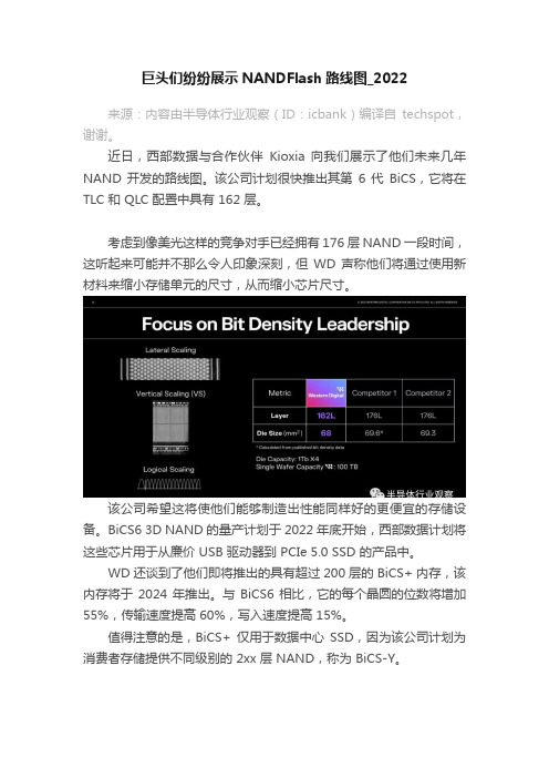
该公司计划很快推出其第6 代BiCS,它将在TLC 和 QLC 配置中具有 162 层。
考虑到像美光这样的竞争对手已经拥有 176 层 NAND 一段时间,这听起来可能并不那么令人印象深刻,但WD 声称他们将通过使用新材料来缩小存储单元的尺寸,从而缩小芯片尺寸。
该公司希望这将使他们能够制造出性能同样好的更便宜的存储设备。
BiCS6 3D NAND 的量产计划于 2022 年底开始,西部数据计划将这些芯片用于从廉价 USB 驱动器到 PCIe 5.0 SSD 的产品中。
WD 还谈到了他们即将推出的具有超过 200 层的 BiCS+ 内存,该内存将于 2024 年推出。
与 BiCS6 相比,它的每个晶圆的位数将增加55%,传输速度提高 60%,写入速度提高 15%。
值得注意的是,BiCS+ 仅用于数据中心SSD,因为该公司计划为消费者存储提供不同级别的 2xx 层 NAND,称为 BiCS-Y。
西部数据还表示,他们正在研究多种技术以提高密度和容量,包括 PLC,并计划在未来十年内构建 500 层以上的 NAND。
总结而言,西部数据计划开始量产162层BiCS6 3D NAND,很可能在今年年底用于PCIe 5 SSD。
该公司还在开发具有200 多层的NAND,用于数据中心存储、PLC,以及将多个3D NAND 晶圆粘合在一起以增加层数的方法。
延伸阅读:美光路线图美光近日表示,公司正在开发 232 层 3D NAND,并制定了 500 多层的路线图。
3D NAND 是通过在垂直堆栈中将多组单元相互层叠来制造的。
闪存芯片中的层数越多,容量就越高。
所有制造商目前都在制造100 层以上的芯片,并有更高层数的前景。
- 1、下载文档前请自行甄别文档内容的完整性,平台不提供额外的编辑、内容补充、找答案等附加服务。
- 2、"仅部分预览"的文档,不可在线预览部分如存在完整性等问题,可反馈申请退款(可完整预览的文档不适用该条件!)。
- 3、如文档侵犯您的权益,请联系客服反馈,我们会尽快为您处理(人工客服工作时间:9:00-18:30)。
NAND Flash Memory Roadmap 2014
Sandisk NAND Memory Roadmap
Source: /English/Collaterals/Proceedings/2013/20130813_Plenary_Shrivastava.pdf
NAND Flash Memory Roadmap 2014
Micron Memory RoamapSource: /2014/02/20/micron-pushes-memory-roadmap-several-routes/
Content for re-use only with TechInsights permission.
NAND Flash Memory Roadmap 2014
Micron 3D NAND Cell
Micron customers won't have to wait long for 3D flash memory CEO Mark Durcan tells CNET that the company will start providing samples of the advanced memory technology to customers in the first quarter of 2014.
Micron plans to make the transition from 2D NAND flash to 3D NAND flash when it's more cost effective. Because Micron already has a good scaling path for 2D NAND flash, it needs to add a lot of layers to 3D NAND flash before it makes economic sense to change over, so it is pursuing both formats in parallel.
NAND Flash Memory Roadmap 2014
Samsung 3D V-NAND
Source: /show/7237/samsungs-vnand-hitting-the-reset-button-on-nand-scaling
Content for re-use only with TechInsights permission.
Content for re-use only with TechInsights permission.
NAND Flash Memory Roadmap 2014
Samsung NAND Flash Roadmap
Source: /show/7237/samsungs-vnand-hitting-the-reset-button-on-nand-scaling
Source: /news/micron-customers-wont-have-to-wait-long-for-3d-flash-memory/ Source: Akira Goda “Opportunities and Challenges of 3D NAND Scaling” International Symposium VLSI Technology, Systems, and Applications (VLSI-TSA), 2013
3D-NAND
3D-NAND Gen 2
(1Y?) 15 nm planar 1Z 15 nm 16 nm planar
1Z 3D-NAND (BiCS)
3D-NAND (BiCS)
3D-NAND?
3D-NAND
Content for re-use only with TechInsights permission.
Technology Roadmap for NAND Flash Memory
April 2014
Content for re-use only with TechInsights permission.
Introduction
NAND Flash is a rapidly changing technology and market. It promises to be very interesting as the process node approaches 10 nm. At this point, physical constraints will begin to limit the performance of the basic memory cell design. As a result, looking more than two years into the future becomes a purely speculative exercise and we limit our projections to 2016.
NAND Flash Memory Roadmap 2014
NAND Technology Quarterly Forecast
Content for re-use only with TechInsights permission.
NAND Flash Memory Roadmap 2014
2013 NAND Production
Contact us for more information: /company/contact-us/ 1-613-599-6500
Content for re-use only with TechInsights permission.
NAND Flash Memory Roadmap 2014
NAND Flash Memory Roadmap 2014
Micron 16 nm MLC NAND
Our 16 nm NAND technology enables the industry’s smallest 128Gb MLC Flash memory device. The 16 nm node is not only the leading Flash process, but it is also the most advanced processing node for any sampling semiconductor device.
Source: /Uploads/file/2013%20NAND%20Flash%20market%20annual%20report.pdf
Content for re-use only with TechInsights permission.
NAND Flash Memory Roadmap 2014
Samsung 3D V-NAND
Source: Ki-Tae Park et al. “Three-Dimensional 128Gb MLC Veritical NAND Flash-Memory with 24-WL Stacked Layers and 50MB/s High-Speed Programming Solid-State Circuits Conference Digest of Technical Papers (ISSCC) 2014 pp334-335 Content for re-use only with TechInsights permission.
Source: /global/business/semiconductor/html/product/flash-solution/vnand/overview.html
Content for re-use only with TechInsights permission.
ITRS Technology Roadmap
Source: ITRS
Content for re-use only with TechInsights permission.
NAND Flash Memory Roadmap 2014
NAND Annual Technology Roadmaps
Manufacturer
ITRS Flash Roadmap
2014
17 nm 1X (19 nm) 1Y (16 nm) planar 3D-NAND (24L) 1x nm 16 nm planar
2015
15 nm 1Z (12 nm) planar 3D-NAND (32L)
2016
14 nm
Content for re-use only with TechInsights permission.
NAND Flash Memory Roadmap 2014
Source: /about/innovations/process-tech Source: /inquirer/feature/2286446/micronbets-on-3d-nand-flash-for-the-future-of-storage Content for re-use only with TechInsights permission.
Content for re-use only with TechInsights permission.
NAND Flash Memory Roadmap 2014
Samsung 3D V-NAND
Samsung's three-dimensional V-NAND (Vertical NAND) flash memory is fabricated using an innovative vertical interconnect process technology to link the 24-layer 3D cell array based on Samsung's 3D Charge Trap Flash (CTF) structure. In Samsung's CTF-based NAND flash architecture, first developed in 2006, an electric charge is temporarily placed in a holding chamber of a non-conductive layer of flash composed of silicon nitride (SiN), instead of using a floating gate, to mitigate interference between neighbouring cells. By making this CTF layer three-dimensional, the reliability and processing speed of our V-NAND has been significantly improved. Furthermore, by applying both of these technologies, Samsung's 3D V-NAND is able to provide over twice the scaling of 20 nm-class planar NAND flash.
