塔式起重机外文翻译、中英对照、英汉互译
塔式起重机有限元分析外文翻译
FEM Optimization for Robot StructureWang Shijun, Zhao Jinjuan*Department of Mechanical Engineering, Xi'an University of TechnologyShaanxi Province, People's Republic of ChinaInstitute of Printing and Packing Engineering, Xi'an University of TechnologyAbstractIn optimal design for robot structures, design models need to he modified and computed repeatedly. Because modifying usually can not automatically be run, it consumes a lot of time. This paper gives a method that uses APDL language of ANSYS 5.5 software to generate an optimal control program, which mike optimal procedure run automatically and optimal efficiency be improved.1)IntroductionIndustrial robot is a kind of machine, which is controlled by computers. Because efficiency and maneuverability are higher than traditional machines, industrial robot is used extensively in industry. For the sake of efficiency and maneuverability, reducing mass and increasing stiffness is more important than traditional machines, in structure design of industrial robot.A lot of methods are used in optimization design of structure. Finite element method is a much effective method. In general, modeling and modifying are manual, which is feasible when model is simple. When model is complicated, optimization time is longer. In the longer optimization time, calculation time is usually very little, a majority of time is used for modeling and modifying. It is key of improving efficiency of structure optimization how to reduce modeling and modifying time.APDL language is an interactive development tool, which is based on ANSYS and is offered to program users. APDL language has typical function of some large computer languages. For example, parameter definition similar to constant and variable definition, branch and loop control, and macro call similar to function and subroutine call, etc. Besides these, it possesses powerful capability of mathematical calculation. The capability of mathematical calculation includes arithmetic calculation, comparison, rounding, and trigonometric function, exponentialfunction and hyperbola function of standard FORTRAN language, etc. By means of APDL language, the data can be read and then calculated, which is in database of ANSYS program, and running process of ANSYS program can be controlled.Fig. 1 shows the main framework of a parallel robot with three bars. When the length of three bars are changed, conjunct end of three bars can follow a given track, where robot hand is installed. Core of top beam is triangle, owing to three bars used in the design, which is showed in Fig.2. Use of three bars makes top beam nonsymmetrical along the plane that is defined by two columns. According to a qualitative analysis from Fig.1, Stiffness values along z-axis are different at three joint locations on the top beam and stiffness at the location between bar 1 and top beam is lowest, which is confirmed by computing results of finite element, too. According to design goal, stiffness difference at three joint locations must he within a given tolerance. In consistent of stiffness will have influence on the motion accuracy of the manipulator under high load, so it is necessary to find the accurate location of top beam along x-axis.To the questions presented above, the general solution is to change the location of the top beam many times, compare the results and eventually find a proper position, The model will be modified according to the last calculating result each time. It is difficult to avoid mistakes if the iterative process is controlled manually and the iterative time is too long. The outer wall and inner rib shapes of the top beam will be changed after the model is modified. To find the appropriate location of top beam, the model needs to be modified repetitiously.Fig. 1 Solution of Original DesignThis paper gives an optimization solution to the position optimization question of the top beam by APDL language of ANSYS program. After the analysis model first founded, the optimization control program can be formed by means of modeling instruction in the log file. The later iterative optimization process can be finished by the optimization control program and do not need manual control. The time spent in modifying the model can be decreased to the ignorable extent. The efficiency of the optimization process is greatly improved.2)Construction of model for analysisThe structure shown in Fig. 1 consists of three parts: two columns, one beam and threedriving bars. The columns and beam are joined by the bolts on the first horizontal rib located on top of the columns as shown in Fig.1. Because the driving bars are substituted by equivalent forces on the joint positions, their structure is ignored in the model.The core of the top beam is three joints and a hole with special purpose, which can not be changed. The other parts of the beam may be changed if needed. For the convenience of modeling, the core of the beam is formed into one component. In the process of optimization, only the core position of beam along x axis is changed, that is to say, shape of beam core is not changed. It should be noticed that, in the rest of beam, only shape is changed but the topology is not changed and which can automatically be performed by the control program.Fig.1, six bolts join the beam and two columns. The joint surface can not bear the pull stress in the non-bolt joint positions, in which it is better to set contact elements. When the model includes contact elements, nonlinear iterative calculation will be needed in the process of solution and the computing time will quickly increase. The trial computing result not including contact element shows that the outside of beam bears pulling stress and the inner of beam bears the press stress. Considering the primary analysis object is the joint position stiffness between the top beam and the three driving bars, contact elements may not used, hut constructs the geometry model of joint surface as Fig.2 showing. The upper surface and the undersurface share one key point in bolt-joint positions and the upper surface and the under surface separately possess own key points in no bolt positions. When meshed, one node will be created at shared key point, where columns and beam are joined, and two nodes will be created at non shared key point, where column and beam are separated. On right surface of left column and left surface of right column, according to trial computing result, the structure bears press stress. Therefore, the columns and beam will share all key points, not but at bolts. This can not only omit contact element but also show the characteristic of bolt joining. The joining between the bottoms of the columns and the base are treated as full constraint. Because the main aim of analysis is the stiffness of the top beam, it can be assumed that the joint positions hear the same as load between beam and the three driving bars. The structure is the thin wall cast and simulated by shell element . The thickness of the outside wall of the structure and the rib are not equal, so twogroups of real constant should he set. For the convenience of modeling, the two columns are also set into another component. The components can create an assembly. In this way, the joint positions between the beam core and columns could he easily selected, in the modifying the model and modifying process can automatically be performed. Analysis model is showed Fig.1. Because model and load are symmetric, computing model is only half. So the total of elements is decreased to 8927 and the total of nodes is decreased to 4341. All elements are triangle.3.)Optimization solutionThe optimization process is essentially a computing and modifying process. The original design is used as initial condition of the iterative process. The ending condition of the process is that stiffness differences of the joint locations between three driving bars and top beam are less than given tolerance or iterative times exceed expected value. Considering the speciality of the question, it is foreseen that the location is existent where stiffness values are equal. If iterative is not convergent, the cause cannot be otherwise than inappropriate displacement increment or deficient iterative times. In order to make the iterative process convergent quickly and efficiently, this paper uses the bisection searching method changing step length to modify the top beam displacement. This method is a little complex but the requirement on the initial condition is relatively mild.The flow chart of optimization as follows:1. Read the beam model data in initial position from backup file;2. Modify the position of beam;3. Solve;4. Read the deform of nodes where beam and three bars are joined;5. Check whether the convergent conditions are satisfied, if not, then continue to modify the beam displacement and return to 3, otherwise, exit the iteration procedure.6. Save the results and then exit.The program's primary control codes and their function commentaries are given in it, of which the detailed modeling instructions are omitted. For the convenience of comparing with the control flow, the necessary notes are added.the flag of the batch file in ANSYSBATCH RESUME, robbak.db, 0read original data from the backupfile robbak,.db/PREP7 enter preprocessordelete the joint part between beam core and columnsmove the core of the beam by one :step lengthapply load and constraint on the geometry meshing thejoint position between beam core and columns FINISH exit the preprocessorISOLU enter solverSOLVE solveFINISH exit the solverPOST1 enter the postprocessor*GET ,front,NODE,2013,U,Z read the deformation of first joint node on beam*GET,back,NODE, 1441 ,U,Z read the deformation of second joint node on beam intoparameter hacklastdif-1 the absolute of initial difference between front and hacklast timeflag=- 1 the feasibility flag of the optimizationstep=0.05 the initial displacement from initial position to the currentposition*D0,1,1,10,1 the iteration procedure begin, the cycle variable is I andits value range is 1-10 and step length is 1dif=abs(front-back) the absolute of the difference between front and hack inthe current result*IF,dif,LE,l .OE-6,THEN check whether the absolute difference dif satisfies therequest or noflag=l yes, set flag equal to 1*EXIT exit the iterative calculation*ELSEIF,dif,GE,lastdif,THEN check whether the dif value becomes great or not flag=2yes, set flag 2 modify step length by bisection methodperform the next iterative calculation, use the lastposition as the current position and modified last steplength as the current step lengthELSE if the absolute of difference value is not less thanexpected value and become small gradually, continue tomove top beam read the initial condition from back upfile enter the preprocessorMEN, ,P51X, , , step,, , ,1 move the core of the beam by one step length modify thejoint positions between beam core and column applyload and constraint meshingFINISH exit preprocessorISOLU enter solverSOLVE solveFINISH exit the solver/POST1 exit the postprocessor*GET,front,NODE,201 3,U,Z read the deformation of first joint node to parameter front *GET,back,NODE, 144 1,U,Z read the deformation of second joint node to parameter back lastdif-dif update the value of last dif*ENDIF the end of the if-else*ENDDO the end of the DO cycleMost of the control program above is copied from log file, which is long. The total of lines is up to about 1000 lines. Many codes such as modeling and post-process codes are used repeatedly. To make the program construct clear, these instructions can he made into macros, which are called by main program. This can efficiently reduce the length of the main program. In addition, modeling instructions from log file includes lots of special instructions that are only used under graphic mode but useless under hatch mode. Deleting and modifying these instructions when under batch mode in ANSYS can reduce the length of the file, too.In the program above, the deformation at given position is read from node deformation. In meshing, in order to avoid generating had elements, triangle mesh is used. In optimization, the shape of joint position between columns and beam continually is changed. This makes total of elements different after meshing each time and then element numbering different, too. Data read from database according to node numbering might not he data to want. Therefore, beam core first needs to he meshed, then saved. When read next time, its numbering is the same as last time.Evaluating whether the final result is a feasible result or not needs to check the flag value. Ifonly the flag value is I, the result is feasible, otherwise the most proper position is not found. The total displacement of top beam is saved in parameter step. If the result is feasible, the step value is the distance from initial position to the most proper position. The sum of iterative is saved in parameter 1. According to the final value of I, feasibility of analysis result and correctness of initial condition can he evaluated.4)Optimization resultsThe sum of iterative in optimization is seven, and it takes about 2 hour and 37 minutes to find optimal position. Fig.3 shows the deformation contour of the half-construct. In Fig.3, the deformations in three joints between beam and the three driving bars is the same as level, and the corresponding deformation range is between -0.133E-04 and -0.1 15E-O4m, the requirement of the same stiffness is reached. At this time, the position of beam core along x-axis as shown in Fig. 1 has moved -0.71E-01m compared with the original designed positionBecause the speed of computer reading instruction is much faster than modifying model manually, the time modifying model can be ignored. The time necessary foroptimization mostly depends on the time of solution. Compared with the optimization procedure manually modifying model, the efficiency is improved and mistake operating in modeling is avoided.5)ConclusionThe analyzing result reveals that the optimization method given in this paper is effective and reaches the expected goal. The first advantage of this method is that manual mistakes do not easily occur in optimization procedure. Secondly, it is pretty universal and the control codes given in this paper may he transplanted to use in similar structure optimization design without large modification. The disadvantage is that the topology structure of the optimization object can not be changed. The more the workload of modifying the model, the more the advantages of this method are shown. In addition, the topology optimization function provided in ANSYS is used to solve the optimization problem that needs to change the topology structure.The better optimization results can he achieved if the method in this paper combined with中文译文:机器人机构优化设计有限元分析王世军赵金娟西安大学机电工程系中国陕西西安大学出版社摘要机器人结构最优化设计,设计模型需要反复的修正和计算。
最新起重机械名词中英文对照

起重机械名词中英文对照1 GB 567-1989 拱形金属爆破片技术条件Specification for domed metallic bursting discs2 GB/T 783-1987 起重机械最大起重量系列Lifting appliance Range of maximun capacitios3 GB/T 790—1995 电动桥式起重机跨度和起升高度系列Overhead travelling crane-—Span series and lifting height series4 GB/T 814—1989 弧形闸门通用技术条件General technical requirements for radial gates5 GB/T 987-1991 带式输送机基本参数与尺寸Belt conveyors—Basic parameters and dimensions6 GB/T 988-1991 带式输送机滚筒基本参数与尺寸Belt conveyor pulleys—Basic parameters and dimensions7 GB/T 990—1991 带式输送机托辊基本参数与尺寸Belt conveyor idlers—Basic parameters and dimensions8 GB/T 994—1977 TD型带式输送机螺旋拉紧装置基本参数与尺寸Screw thread belt tighteners for type TD belt conveyor-Specifications9 GB/T 995—1977 TD型带式输送机垂直拉紧装置基本参数与尺寸Vertical belt tighteners for type TD belt conveyor—Specificati10 GB/T 996-1977 TD型带式输送机车式拉紧装置基本参数与尺寸Trolley type belt tighteners for type TD belt conveyor—Specifications11 GB/T 1236—1985 通风机空气动力性能试验方法Test methods of aerodynamic performance for fans12 GB/T 2817-1991 井用潜水泵技术条件Specification for submersible pumps for deep well13 GB/T 2888-1991 风机和罗茨鼓风机噪声测量方法Methods of noise measurement for fans, blowers compressors and Roots blowers14 GB/T 3163-1993 真空技术术语Terminology for vacuum technology15 GB/T 3164-1993 真空技术系统图用图形符号Vacuum technology--Graphical symbols16 GB/T 3214-1991 水泵流量的测定方法Methods for measurement of capacity of pump17 GB/T 3215-1982 炼厂、化工及石油化工流程用离心泵通用技术条件Centrifugal pumps for refinery,chemical and petrochemical processes——General technical specifications18 GB/T 3216-1989 离心泵、混流泵、轴流泵和旋涡泵试验方法Test methods for centrifugal, mixed flow, axial and regenerative pumps19 GB/T 3235—1982 通风机基本型式、尺寸、参数及性能曲线Basic types,sizes,parameters and characteristics of fans20 GB/T 3264—1989 单张纸平版胶印机技术条件Specification for sheet—fed planographic offset press21 GB/T 3811—1983 起重机设计规范Design rules for cranes22 GB/T 4307-1984 起重吊钩名词术语Lifting hooks——Nomenclature23 GB/T 4652-1984 双臂式装载机试验方法Method for testing the gathering arm loaders24 GB/T 4774—1984 离心机和过滤机名词术语Terminology of centrifuge and filter25 GB/T 4975-1995 容积式压缩机术语总则Displacement compressors vocabulary-—General26 GB/T 4976-1985 压缩机分类Compressors——Classification27 GB/T 4980—1985 容积式压缩机噪声声功率级的测定-—工程法Determination of sound power level for noise emitted by displacement compressors—-Engineering method28 GB/T 4983-1985 拧紧型真空快卸法兰Vacuum technology screwed type quick release flange29 GB 5099—1994 钢质无缝气瓶Seamless steel gas cylinders30 GB 5100-1994 钢质焊接气瓶Welded steel gas cylinders31 GB/T 5140—1985 叉车挂钩型货叉术语Fork lift trucks—-Hook—on type fork arms--V ocabulary32 GB/T 5141—1985 平衡重式叉车稳定性基本试验Counter balanced lift trucks--Stability-—Basic tests33 GB/T 5142-1985 前移式和插腿式叉车稳定性试验Reach and straddle fork lift trucks--Stability tests34 GB 5143-1985 高起升车辆护顶架技术要求和试验方法High-lift rider trucks—-Overhead guards—-Specification and testing35 GB/T 5182-1996 叉车货叉技术要求和试验Fork—lift trucks——Fork arms——Technical characteristics and testing36 GB/T 5183-1985 叉车货叉的尺寸Fork lift trucks—-Fork arms--Dimensions37 GB/T 5184-1996 叉车挂钩型货叉和货叉架安装尺寸Fork-lift trucks-—Hook-on type fork arms and fork arm carriages—-Mounting dimensions38 GB/T 5621—1985 凿岩机械与气动工具性能试验方法Test methods of performance for rock drilling machines and pneumatic tools39 GB/T 5656—1994 离心泵技术条件(II类) Technical specifications for centrifugal pumps-—Class II40 GB/T 5657—1995 离心泵技术条件(I类) Technical specifications for centrifugal pumps-—Class I41 GB/T 5660—1985 轴向吸入离心泵底座尺寸和安装尺寸End-suction centrifugal pumps-—Baseplate and installation dimensions42 GB/T 5661-1985 轴向吸入离心泵机械密封和软填料用的空腔尺寸End-suction centrifugal pumps--Dimensions of cavities for mechanical seals and for soft packing43 GB/T 5662—1985 轴向吸入离心泵(16 bar) 标记、性能和尺寸End-suction centrifugalpumps (rating 16 bar)——Designation,nominal duty point and dimensions44 GB/T 5773-1986 容积式制冷压缩机性能试验方法The methods of performance test for positive displacement refrigerant compressor45 GB 5842-1996 液化石油气钢瓶Liquefied petroleum gas cylinders46 GB/T 5905-1986 起重机试验规范和程序Cranes-—Test code and procedures47 GB/T 5973—1986 钢丝绳用楔形接头Cuneiform conector for use with steel wire ropes48 GB/T 5974。
塔式起重机常用英语词汇(USUAL ENGLISH ON TOWER CRANE)
CHECK 核对 he dui
CLIMBING CLAW 上升脚爪 shang sheng jiao zhua
CONNECTOR 连接器 lian jie qi
DISMANTLE 拆卸 chai xie
DRAWING 制图 zhi tu
MAINTENANCE 维修,保养 wei xiu, bao yang
MOTOR 发动机,电动机 fa dong ji, dian dong ji
MAST 发射天线 fa she tian xian
MATERIAL 原料 yuan liao
MECHANISM 机械装置 ji xie zhuang zhi
ISOLATED SWITCH 独立开关 du li kai guan
INWARD 向内,内在的 xiang nei, nei zai de
ISOLATION 隔离 ge li
INDICATOR LIGHT 指示灯 zhi shi deng
JIB 转臂,支架 zhuan bi, zhi jia
CONTROL CIRCUIT 控制电路 kong zhi dian lu
CONNECTION 连接,线路 lian jie,xian lu
CONTROL BOX 控制箱,控制台 kong zhi xiang,kong zhi tai
COMPONENT 部分 bu fen
CONTACTOR 开关 kai guan
CABIN 驾驶室 jia shi shi
CLIMBING FRAME 上升结构 shang sheng jie gou
【工程机械英法汉三语】图文对照英语和法语-词汇(一)
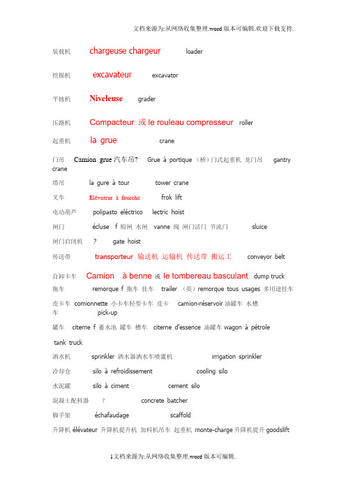
装载机chargeuse chargeur loader挖掘机excavateur excavator平地机Niveleuse grader压路机Compacteur 或le rouleau compresseur roller起重机la grue crane门吊Camion grue汽车吊? Grue à portique (桥)门式起重机龙门吊gantry crane塔吊 la gure à tour tower crane叉车Elévateur àfourche frok lift电动葫芦polipasto eléctrico lectric hoist闸门écluse f 船闸水闸vanne 阀闸门活门节流门sluice闸门启闭机 ? gate hoist传送带transporteur 输送机运输机传送带搬运工 conveyor belt自卸卡车Camion à benne或le tombereau basculant dump truck拖车remorque f 拖车挂车 trailer (英)remorque tous usages 多用途挂车皮卡车 comionnette 小卡车轻型卡车皮卡camion-réservoir油罐车水槽车pick-up罐车 citerne f 蓄水池罐车槽车citerne d’essence 油罐车 wagon à pétroletank truck洒水机 sprinkler 洒水器洒水车喷灌机irrigation sprinkler冷却仓silo à refroidissement cooling silo水泥罐 silo à ciment cement silo混凝土配料器?concrete batcher脚手架échafaudage scaffold升降机 élévateur 升降机提升机加料机吊车起重机monte-charge升降机提升goodslift强制式搅拌机 mélangeur 或者agitateur forcé ? forced mixer自落式搅拌机mélangeur agitateur brasseur 搅拌机混合器 concrete self falling mix er手锤 marteau marteau-piqueur 手风钻风镐marteau-batteur 打夯机桩锤hand hammer 楔子cheville 销子销钉coin 隅角落楔xie子wedge 长柄镘 palette?f 板板状物小铲spatula砌砖刀? masonry trowel木镘刀spatule f 刮刀抹刀spatula铁镘truelle f 镘抹子泥刀修平刀钢镘刀truelle en acier 英trowel 羊角锤marteau ? arrache-clou 起钉钳claw hammer管钳?pipe wrench手推车char chariot la brouette 独轮车wheelbarrow夹钳 pince clamp 法语也有医用的英:clamp錾子 ciseau 凿子剪刀chisel镘灰板?hawk垂球 plomb 铅测深锤水陀plumb bob锯 scie f scier 锯v. saw手锯 scie à main scie à manche hand saw破碎锤 ? breaking hammer石膏plâtre gypse 石膏灰泥板 plaster 石膏像statue en plâtre混凝土 béton concrete骨料 agrégat aggregate砾石 gravier gravier à béton 混凝土用砾石 grave 沙砾料砾石grave cim ent 水泥砂砾料gravel砂浆 mortier mortier de ciment 水泥砂浆mortier de chaux 石灰浆mortier de plâtre 石膏砂浆mortar粘土 argile f argile blanche 白泥高岭土clay火山岩lave lava玄武岩basalte basalt花岗岩granit(e) granite单成岩 monolithe bloc de pierre monolith土坯adobe adobe混凝土板 plaque de béton dalle en béton armé 钢筋混凝土板英语concrete slab 法语钢筋混凝土dalle en béton armé塑料泡沫plastique mousseux styrofoam镀锌钢板plaque d‘acier galvanisé galvanized steel plate沥青 asphalte m asphalte à chaud /à froid 冷沥青热沥青 asphalt。
塔机中英文对照表
塔机中英文对照表动臂起重机Luffing Jib Tower Crane 平头起重机Flat-top Tower Crane标记mark重量weight比例scale工艺technics审核verify设计Design数量Ammount文件File校对check标准化Standardization批准ratify材料material单个single总的Total滑轮pulley拉杆tie bar平台platporm附着Anchorages起升机构Hoisting Mechanism变幅机构Trolleying Mechanism回转机构Slewing Mechanism行走机构Travelling Mechanism顶升机构lifting mechanism绕绳量Rope Length标准速度Standard Velocity容绳量Rope capacity平衡臂counter-jib臂架jib小车Trolley塔顶cat-head电控柜electrical control cabinet 工具箱toolbox 主电源电缆main power cable定位架positioning frame固定支腿fixing angle配套零件matching parts平衡重counter weight吊钩hook螺栓bolt螺母nut销pin开口销split-pin轴axle轴线axis角钢angle steel垫圈washer标准件standard parts隔套spacer板plate圆钢round steel低碳钢Low carbon steel圆管钢Steel pipe钢板网steel net槽钢beam channelA字架A-frame契块wedge滚轮roller油缸cylinder梯子ladder法兰盘flange plate示意图figure排绳装置rope guide回转支撑slewing ring平衡臂端部节counter jib nose平衡臂根部节counter jib foot卷筒drum组件component焊件weldment倍率Magnification最大起重力矩Max.hoisting moment最大工作幅度Max.working radius最小工作幅度Min.working radius臂根铰点最大高度Max.height of pivot at jib root。
起重机用语中英文对照
摄像机升降架; 照相机三脚架
cantilever crane
悬臂吊车
cantilever walking crane
壁装移动式悬臂起重机
canton crane
轻便落地吊车
capping crane
加盖起重机
cargo crane
船货起重机; 码头起重机
carrying capacity of crane
crane rail crane rating crane rope crane runner crane runway crane runway girder crane saver crane scale crane shaft crane ship crane stake crane switch crane trolley crane trolley wire crane truck crane weigher crane wheel crane winch crane with double lever jib craneage craneman crane-type loader crawler crane crawling crane crow crane deck crane deck twin crane depiling crane de-piling crane derrick crane derrick wagon crane derricking jib crane dividing stationary tower crane dock crane dogging crane donkey crane dove's foot cranesbill economical gantry crane electric cater-pillar crane electric crane electric double-beam bridge crane electric gantry crane electric jib crane electric locomotive crane
起重机的历史外文文献翻译、中英文翻译
The History of Crane1. OverviewThe first construction cranes were invented by the Ancient Greeks and were powered by men or beasts of burden, such as donkeys. These cranes were used for the construction of tall buildings. Larger cranes were later developed, employing the use of human treadwheels, permitting the lifting of heavier weights. In the High Middle Ages, harbor cranes were introducedto load and unload ships and assist with their construction – some were built into stone towers for extra strength and stability. The earliest cranes were constructed from wood, but cast iron and steel took over with the coming of the Industrial Revolution.For many centuries, power was supplied by the physical exertion of men or animals, although hoists in watermills and windmills could be driven by the harnessed natural power. The first 'mechanical' power was provided by steam engines, the earliest steam crane being introducedin the 18th or 19th century, with many remaining in use well into the late 20th century. Modern cranes usually use internal combustion engines or electric motors and hydraulic systems to provide a much greater lifting capability than was previously possible, although manual cranes are still utilized where the provision of power would be uneconomic.Cranes exist in an enormous variety of forms – each tailored to a specific use. Sizes range from the smallest jib cranes, used inside workshops, to the tallest tower cranes, used for constructing high buildings. For a while, mini - cranes are also used for constructing high buildings, in order to facilitate constructions by reaching tight spaces. Finally, we can find larger floating cranes, generally used to build oil rigs and salvage sunken ships. This article also covers lifting machines that do not strictly fit the above definition of a crane, but are generally known as cranes, such as stacker cranes and loader cranes.2. History(1)Ancient GreeceThe crane for lifting heavy loads was invented by the Ancient Greeks in the late 6th century BC. The archaeological record shows that no later than c.515 BC distinctive cuttings for both lifting tongs and lewis irons begin to appear on stone blocks of Greek temples. Since these holes point at the use of a lifting device, and since they are to be found either above the center of gravity of the block, or in pairs equidistant from a point over the center of gravity, they are regarded by archaeologists as the positive evidence required for the existence of the crane.The introduction of the winch and pulley hoist soon lead to a widespread replacement of ramps as the main means of vertical motion. For the next two hundred years, Greek building sites witnesseda sharp drop in the weights handled, as the new lifting technique made the use of several smaller stones more practical than of fewer larger ones. In contrast to the archaic period with its tendencyto ever-increasing block sizes, Greek temples of the classical age like the Parthenon invariably featured stone blocks weighing less than 15-20 tons. Also, the practice of erecting large monolithic columns was practically abandoned in favor of using several column drums.Although the exact circumstances of the shift from the ramp to the crane technology remain unclear, it has been argued that the volatile social and political conditions of Greece were moresuitable to the employment of small, professional construction teams than of large bodies of unskilled labor, making the crane more preferable to the Greek polis than the more labor-intensive ramp which had been the norm in the autocratic societies of Egypt or Assyria.The first unequivocal literary evidence for the existence of the compound pulley system appears in the Mechanical Problems (Mech. 18, 853a32-853b13) attributed to Aristotle (384-322 BC), but perhaps composed at a slightly later date. Around the same time, block sizes at Greek temples began to match their archaic predecessors again, indicating that the more sophisticated compound pulley must have found its way to Greek construction sites by then.Ancient RomeThe heyday of the crane in ancient times came during the Roman Empire, when construction activity soared and buildings reached enormous dimensions. The Romans adopted the Greek crane and developed it further. We are relatively well informed about their lifting techniques, thanks to rather lengthy accounts by the engineers Vitruvius (De Architectura 10.2, 1-10) and Heron of Alexandria (Mechanica 3.2-5). There are also two surviving reliefs of Roman treadwheel cranes, with the Haterii tombstone from the late first century AD being particularly detailed.The simplest Roman crane, the Trispastos, consisted of a single-beam jib, a winch, a rope, and a block containing three pulleys. Having thus a mechanical advantage of 3:1, it has been calculated that a single man working the winch could raise 150 kg (3 pulleys x 50 kg = 150), assuming that 50 kg represent the maximum effort a man can exert over a longer time period. Heavier crane types featured five pulleys (Pentaspastos) or, in case of the largest one, a set of three by five pulleys (Polyspastos) and came with two, three or four masts, depending on the maximum load. The Polyspastos, when worked by four men at both sides of the winch, could already lift 3000 kg (3 ropes x 5 pulleys x 4 men x 50 kg = 3000 kg). In case the winch was replaced by a treadwheel, the maximum load even doubled to 6000 kg at only half the crew, since the treadwheel possesses a much bigger mechanical advantage due to its larger diameter. This meant that, in comparison to the construction of the Egyptian Pyramids, where about 50 men were needed to move a 2.5 ton stone block up the ramp (50 kg per person), the lifting capability of the Roman Polyspastos proved to be 60 times higher (3000 kg per person).However, numerous extant Roman buildings which feature much heavier stone blocks than those handled by the Polyspastos indicate that the overall lifting capability of the Romans went far beyond that of any single crane. At the temple of Jupiter at Baalbek, for instance, the architrave blocks weigh up to 60 tons each, and one corner cornice block even over 100 tons, all of them raised to a height of about 19 m. In Rome, the capital block of Trajan's Column weighs 53.3 tons, which had to be lifted to a height of about 34 m (see construction of Trajan's Column).It is assumed that Roman engineers lifted these extraordinary weights by two measures (see picture below for comparable Renaissance technique): First, as suggested by Heron, a lifting tower was set up, whose four masts were arranged in the shape of a quadrangle with parallel sides, not unlike a siege tower, but with the column in the middle of the structure (Mechanica 3.5). Second, a multitude of capstans were placed on the ground around the tower, for, although having a lower leverage ratio than treadwheels, capstans could be set up in higher numbers and run by more men (and, moreover, by draught animals). This use of multiple capstans is also described by AmmianusMarcellinus (17.4.15) in connection with the lifting of the Lateranense obelisk in the Circus Maximus (ca. 357 AD). The maximum lifting capability of a single capstan can be established by the number of lewis iron holes bored into the monolith. In case of the Baalbek architrave blocks, which weigh between 55 and 60 tons, eight extant holes suggest an allowance of 7.5 ton per lewis iron, that is per capstan. Lifting such heavy weights in a concerted action required a great amount of coordination between the work groups applying the force to the capstans.Middle AgesDuring the High Middle Ages, the treadwheel crane was reintroduced on a large scale after the technology had fallen into disuse in western Europe with the demise of the Western Roman Empire. The earliest reference to a treadwheel (magna rota) reappears in archival literature in France about 1225, followed by an illuminated depiction in a manuscript of probably also French origin dating to 1240. In navigation, the earliest uses of harbor cranes are documented for Utrecht in 1244, Antwerp in 1263, Brugge in 1288 and Hamburg in 1291, while in England the treadwheel is not recorded before 1331.Generally, vertical transport could be done more safely and inexpensively by cranes than by customary methods. Typical areas of application were harbors, mines, and, in particular, building sites where the treadwheel crane played a pivotal role in the construction of the lofty Gothic cathedrals. Nevertheless, both archival and pictorial sources of the time suggest that newly introduced machines like treadwheels or wheelbarrows did not completely replace more labor-intensive methods like ladders, hods and handbarrows. Rather, old and new machinery continued to coexist on medieval construction sites and harbors.Apart from treadwheels, medieval depictions also show cranes to be powered manually by windlasses with radiating spokes, cranks and by the 15th century also by windlasses shaped like a ship's wheel. To smooth out irregularities of impulse and get over 'dead-spots' in the lifting process flywheels are known to be in use as early as 1123.The exact process by which the treadwheel crane was reintroduced is not recorded, although its return to construction sites has undoubtedly to be viewed in close connection with the simultaneous rise of Gothic architecture. The reappearance of the treadwheel crane may have resulted from a technological development of the windlass from which the treadwheel structurally and mechanically evolved. Alternatively, the medieval treadwheel may represent a deliberate reinvention of its Roman counterpart drawn from Vitruvius' De architectura which was available in many monastic libraries. Its reintroduction may have been inspired, as well, by the observation of the labor-saving qualities of the waterwheel with which early treadwheels shared many structural similarities.Structure and placementThe medieval treadwheel was a large wooden wheel turning around a central shaft with a treadway wide enough for two workers walking side by side. While the earlier 'compass-arm' wheel had spokes directly driven into the central shaft, the more advanced 'clasp-arm' type featured arms arranged as chords to the wheel rim, giving the possibility of using a thinner shaft and providing thus a greater mechanical advantage.Contrary to a popularly held belief, cranes on medieval building sites were neither placed on the extremely lightweight scaffolding used at the time nor on the thin walls of the Gothic churches which were incapable of supporting the weight of both hoisting machine and load. Rather, cranes were placed in the initial stages of construction on the ground, often within the building. When a new floor was completed, and massive tie beams of the roof connected the walls, the crane was dismantled and reassembled on the roof beams from where it was moved from bay to bay during construction of the vaults. Thus, the crane ‘grew’ and ‘wandered’ with the building with the result that today all extant construction cranes in England are found in church towers above the vaulting and below the roof, where they remained after building construction for bringing material for repairs aloft.Less frequently, medieval illuminations also show cranes mounted on the outside of walls with the stand of the machine secured to putlogs.Mechanics and operationIn contrast to modern cranes, medieval cranes and hoists - much like their counterparts in Greece and Rome - were primarily capable of a vertical lift, and not used to move loads for a considerable distance horizontally as well. Accordingly, lifting work was organized at the workplace in a different way than today. In building construction, for example, it is assumed that the crane lifted the stone blocks either from the bottom directly into place, or from a place opposite the centre of the wall from where it could deliver the blocks for two teams working at each end of the wall. Additionally, the crane master who usually gave orders at the treadwheel workers from outside the crane was able to manipulate the movement laterally by a small rope attached to the load. Slewing cranes which allowed a rotation of the load and were thus particularly suited for dockside work appeared as early as 1340. While ashlar blocks were directly lifted by sling, lewis or devil's clamp (German Teufelskralle), other objects were placed before in containers like pallets, baskets, wooden boxes or barrels.It is noteworthy that medieval cranes rarely featured ratchets or brakes to forestall the load from running backward. This curious absence is explained by the high friction force exercised by medieval treadwheels which normally prevented the wheel from accelerating beyond control. Harbor usageAccording to the "present state of knowledge" unknown in antiquity, stationary harbor cranes are considered a new development of the Middle Ages. The typical harbor crane was a pivoting structure equipped with double treadwheels. These cranes were placed docksides for the loading and unloading of cargo where they replaced or complemented older lifting methods like see-saws, winches and yards.Two different types of harbor cranes can be identified with a varying geographical distribution: While gantry cranes which pivoted on a central vertical axle were commonly found at the Flemish and Dutch coastside, German sea and inland harbors typically featured tower cranes where the windlass and treadwheels were situated in a solid tower with only jib arm and roof rotating. Interestingly, dockside cranes were not adopted in the Mediterranean region and the highly developed Italian ports where authorities continued to rely on the more labor-intensive method ofunloading goods by ramps beyond the Middle Ages.Unlike construction cranes where the work speed was determined by the relatively slow progressof the masons, harbor cranes usually featured double treadwheels to speed up loading. The two treadwheels whose diameter is estimated to be 4 m or larger were attached to each side of the axle and rotated together. Today, according to one survey, fifteen treadwheel harbor cranes from pre-industrial times are still extant throughout Europe.[28] Beside these stationary cranes, floating cranes which could be flexibly deployed in the whole port basin came into use by the 14th century.RenaissanceA lifting tower similar to that of the ancient Romans was used to great effect by the Renaissance architect Domenico Fontana in 1586 to relocate the 361 t heavy Vatican obelisk in Rome. From his report, it becomes obvious that the coordination of the lift between the various pulling teams required a considerable amount of concentration and discipline, since, if the force was not applied evenly, the excessive stress on the ropes would make them rupture.Early modern ageCranes were used domestically in the 17th and 18th century. The chimney or fireplace crane was used to swing pots and kettles over the fire and the height was adjusted by a trammel.4. Types of the cranesMobileMain article: Mobile craneThe most basic type of mobile crane consists of a truss or telescopic boom mounted on a mobile platform - be it on road, rail or water.FixedExchanging mobility for the ability to carry greater loads and reach greater heights due to increased stability, these types of cranes are characterized that they, or at least their main structure does not move during the period of use. However, many can still be assembled and disassembled.外文翻译起重机的历史1. 概况第一台具有机械结构的起重机是由古希腊人发明的,并且由人或者是牲畜比如驴,作为动力源。
中英文对照起重机术语大全
中英文对照起重机术语大全起重机(crane)moblie crane 移动式起重机truck crane 汽车式起重机wheel crane / wheeled crane 轮胎起重机crawler crane / caterpillar crane 履带吊;履带式起重机tower crane 塔吊; 塔式起重机-construction tower cranes / building tower crane 建筑塔式起重机,建筑塔机-luffing jib tower crane 动臂塔式起重机-tower jib crane 塔式挺杆起重机(含义与上同)bridge crane/traveling crane/overhead crane 桥吊;桥式吊车; 桥式起重机-electric traveling crane 电动桥式起重机(俗称行车、天车)-electric double-beam bridge crane 电动双梁桥式起重机portal crane / portal bridge crane门式起重机- semi-goliath crane 半门式起重机- semi-portal bridge crane 半龙门起重机gantry cranes 龙门起重机- rubber tyred gantry crane 轮胎式龙门吊- electric gantry crane 电动龙门式起重机- hook gantry crane 吊钩龙门吊- economical gantry crane 简单龙门起重机; 简易龙门起重机- rubber tyred container gantry crane 轮胎式集装箱龙门起重机barges / floating Cranes 船式起重机; 浮吊; 浮式起重机水上起重机boom crane 吊杆起重机; 桁梁起重机; 臂式起重机; 伸臂起重机bucket crane 料罐起重机; 吊斗起重机building crane 建筑起重机cable crane 索道起重机; 缆索起重机container crane 集装箱起重机electric crane 电动吊车; 电动起重机; 电力起重机electriomagnet crane 电磁铁起重机electric jib crane 电动单臂起重机fixed crane 固定式起重机climbing crane 爬升式起重机;攀爬式起重机fixed derrick crane 固定式动臂起重机fixed jib crane 固定式悬臂起重机flying crane helicopter 起重直升机hoist crane 起重葫芦hoisting crane 升降起重机hook type crane 钩式起重机twin hood crane 双钩吊车mobile crane 移动式吊车; 移动式起重机quay crane 码头起重机; 码头桥式起重机; 港岸起重机revolving track crane 回转式轨道起重机circular crane 旋转式吊车环形吊车roof crane 屋顶起重机transporter crane 桁架式起重机electric crane 电动吊车; 电动起重机gasoline crane 汽油起重机hydraulic crane 液力起重机; 液压起重机derrick crane 人字扒杆人字起重机-travelling derrick crane 移动式人字扒杆jib crane / cantilever crane 悬臂式起重机wall crane 壁式起重机heavy duty crane 重型起重机crane output / carrying capacity of crane / lifting capacity of crane 吊车起重能力crane load 起重机起重量; 起重机起重量crane rating 起重机定额; 起重机载重量crane radius 起重机起吊半径; 起重机伸臂活动半径; 起重机伸距craneage 吊车工时crane beam 行车梁起重机大梁crane stair 起重机楼梯hoist drive mechanism 起重机驱动机构travelling crab 起重机小车hoisting controller 起重控制器吊车控制手柄hoisting facility 起重设施lifting gear 起重装置crane (runway) girder 吊车梁crane support wall 吊车支承墙crane boom 起重机吊架; 起重架; 吊车臂; 吊车起重扒杆; 吊杆crane column 吊车柱crane hook / grab (or lift hook)( or dolly)起重机吊钩crane jib 起重机吊杆crane bridge 起重机桥crane buffer 吊车缓冲器crane rope / crane cable起重钢绳; 起重机吊索; 吊车钢丝绳crane carriage 起重小车; 横行小车crane carrier 起重机载运车crane controller 起重控制器crane fall 起重机索crane motor / crane hoist type motor 起重机电动机crane platform 起重机平台crane rail 吊车轨,起重机轨道crane runner 吊车司机crane runway 起重机走道; 天车滑道crane weigher 吊车秤crane wheel 吊车车轮lifting tackle 起重滑车lever of crane 起重机臂hoisting tools 起重工具吊具lifting rope 吊绳起重钢丝绳起重吊装术语:hoist / load up 起升lower / load down 下降hoist slowly / load up slowly 微微起升lower slowly / load down slowly 微微下降use main hoist/use main line 使用主钩use whip hoist/use whip line 使用小钩raise boom / boom up(臂架类吊车)抬起主臂lower boom / boom down (同上)降下主臂raise boom slowly / boom up slowly(臂架类吊车)微微抬起主臂lower boom slowly / boom down slowly (同上)微微降下主臂swing (根据指挥手势、旗语或)移动摆动stop 停止Emergency stop 紧急停止Extend boom / extend hydranlic boom (汽车吊类)伸长主臂Retract boom / shorten hydranlic boom (汽车吊类)缩回主臂raise the boom and lower the load /boom up and load down (汽车吊类)抬主臂降主钩(俗称顿杆松钩)lower the boom and raise the load /boom dwon and load up (汽车吊类)降主臂起主钩(俗称趴杆起钩)turn left 向左转turn right 向右转crane output / carrying capacity of crane / lifting capacity of crane 吊车起重能力crane load 起重机起重量; 起重机起重量crane rating 起重机定额; 起重机载重量crane radius 起重机起吊半径; 起重机伸臂活动半径; 起重机伸距craneage 吊车工时crane beam 行车梁起重机大梁crane stair 起重机楼梯hoist drive mechanism 起重机驱动机构travelling crab 起重机小车hoisting controller 起重控制器吊车控制手柄hoisting facility 起重设施lifting gear 起重装置crane (runway) girder 吊车梁crane support wall 吊车支承墙crane boom 起重机吊架; 起重架; 吊车臂; 吊车起重扒杆; 吊杆crane column 吊车柱crane hook / grab (or lift hook)( or dolly)起重机吊钩crane bridge 起重机桥crane buffer 吊车缓冲器crane rope / crane cable起重钢绳; 起重机吊索; 吊车钢丝绳crane carriage 起重小车; 横行小车crane carrier 起重机载运车crane controller 起重控制器crane fall 起重机索crane motor / crane hoist type motor 起重机电动机crane platform 起重机平台crane rail 吊车轨,起重机轨道crane runner 吊车司机crane runway 起重机走道; 天车滑道crane weigher 吊车秤crane wheel 吊车车轮crane winch 起重机绞车lifting tackle 起重滑车lever of crane 起重机臂hoisting tools 起重工具吊具lifting rope 吊绳起重钢丝绳。
起重机名称翻译
arm crane 挺杆起重机; 横臂起重机abutment crane 台座起重机; 高座起重机ammunition crane 重炮装弹机crab trolley type wall crane 绞车式壁装起重机crane 用起重机起吊; 鹤; 吊车; 起重机; 升降架crane (runway) girder 吊车梁crane barge 起重机驳船; 起重机船crane beam 行车梁crane boom 起重机吊架; 起重架; 吊车臂; 吊车起重扒杆; 吊杆crane bridge 起重机桥crane buffer 吊车缓冲器crane cable 吊索crane car 汽车起重机crane carriage 起重小车; 横行小车crane carrier 起重机载运车crane controller 起重控制器crane fall 吊车索crane for placing stoplogs 叠梁闸门起门机crane grab 起重机抓斗crane hoist 移动起重机crane ladle 吊包; 吊车浇包crane link 吊车吊架crane load 吊车起重量; 起重机起重量crane loading 起重机起吊; 起重机装运crane locomotive 起重机车crane magnet 电磁吸盘crane motor 吊车电动机crane output 起重能力crane platform 吊车平台crane radius 起重机起吊半径; 起重机伸臂活动半径; 起重机伸距crane rail 吊车轨crane rating 起重机定额; 起重机载重量crane rope 起重钢绳; 起重机吊索; 吊车钢丝绳crane runner 吊车司机crane runway 起重机走道; 天车滑道crane runway girder 起重机行车大梁crane saver 料垛送进装置crane scale 吊车衡crane shaft 起重机轴crane ship 水上起重机crane stake 起重机柱crane switch 起重机开关crane trolley 起重机行车; 吊机滑车crane trolley wire 起重机接触导线; 行车接触导线crane truck 汽车起重机; 吊车; 车载起重机; 车装起重机; 卡车起重机crane weigher 吊车秤crane wheel 吊车车轮crane winch 起重机绞车crane with double lever jib 四连杆伸臂起重机; 四连杆式伸臂起重机crane-type loader 起重机式装载机; 转臂式装载机craneage 吊车工时craneman 吊车工; 起重机手; 天车工crawler crane 履带吊; 履带起重机; 履带式起重机crawling crane 履带起重机; 履带式起重机crow crane 料耙起重机de-piling crane 叠板卸垛吊车deck crane 甲板起重机deck twin crane 并列式甲板起重机depiling crane 叠板卸垛吊车derrick crane 动臂起重机; 转臂起重机derrick wagon crane 车座人字起重机; 车座人字形起重机derricking jib crane 人字式转臂起重机dividing stationary tower crane 分立固定式塔吊dock crane 码头起重机; 船坞起重机; 造船起重机dogging crane 钳式吊车; 夹钳吊车donkey crane 辅助起重机dove's foot cranesbill 柔毛老鹤草economical gantry crane 简单龙门起重机; 简易龙门起重机electric cater-pillar crane 电动履带起重机electric crane 电动吊车; 电动起重机; 电力起重机electric double-beam bridge crane 电动双梁桥式起重机electric gantry crane 电动龙门式起重机electric jib crane 电动单臂起重机electric locomotive crane 电动机车起重机electric monorail crane 电动单轨起重机electric motor-operated fixed crane 固定式电动起重机electric overhead travelling crane 电动桥式起重机electric single beam crane 电动单梁起重机electric single-beam bridge crane 电动单梁桥式起重机electric slewing crane 电动旋臂起重机electric travel(l)ing crane 电力移动起重机electric travelling crane 电动移动式起重机; 电力移动式起重机electric two-beam bridge crane 电动双梁桥式起重机electric tyre crane 电动轮胎起重机electrical bibeam bridge crane 电动双梁桥式起重机(EOT crane) 电动桥式起重机(EOT crane) 电动桥式起重机electromagnetic crane 电磁铁起重机electromagnetic disk single-track crane 电磁盘式单轨吊cover crane 地行揭盖吊车electronic crane scale 电子吊秤erecting crane 装配吊车; 安装用起重机erection crane 安装起重机electromagnetic gantry crane 电磁龙门吊fixed boom crane 定臂起重机fixed crane 固定式起重机fixed derrick crane 固定式动臂起重机fixed gantry crane 固定门式起重机; 固定式龙门起重机fixed gauntry crane 固定龙门起重机fixed jib crane 固定式悬臂起重机floating crane 浮动起重机; 浮式起重机; 浮筒起重机; 水上起重机floating jib crane 水上悬臂起重机flying crane helicopter 起重直升机forging crane 锻造起重机foundry slewing crane 翻砂间旋臂起重机farm crane 农用起重机full-rotating crane 全转式起重机angle crane 斜座起重机; 三角架起重机antiswing crane 防摆动起重机crab crane 钳式吊车arm of crane 吊车臂articulated hydraulic crane 关节液力起重机Babcok and Wilcox type luffing crane 巴韦型俯仰起重机balance crane 平衡起重机; 平衡式起重机bar crane 杆式起重机gasoline crane 汽油起重机geared crane ladle 手摇吊包giant crane 巨型起重机; 巨型起重机bar iron crane 铁条起重机barge crane 船式起重机; 浮吊; 浮式起重机goliath crane 巨型起重机; 巨型起重机; 强力起重机; 移动式巨型起重机; 高架起重机beam crane 单梁起重机grab bucket crane 抓斗起重机grab crane 抓岩机吊车black-necked crane 黑颈鹤block crane 钢锭起重机block setting crane 钢块起重机boat crane 吊艇起重机boom crane 吊杆起重机; 桁梁起重机; 臂式起重机; 伸臂起重机ground-handling crane 地面使用起重机guy derrick crane 牵索人字起重机; 牵索转臂起重机half-gantry crane 单脚高架起重机boom derrick crane 支臂桅杆起重机bow charging crane 船头装货起重机bracket crane 悬臂吊车breakdown crane 拆卸起重机; 应急起重机; 救险吊车; 救险吊车breakdown crane (铁路的) 事故起重机breakdown crane wagon 事故起重车hand crane 手动起重机bridge crane 桥式吊车; 桥式起重机with level luffing crane 装有起重杆升降设备的桥式起重机with level luffing crane 装有起重杆升降设备的桥式起重机hand slewing crane 手旋起重机hand slewing crane (小型) 手推旋转起重机hand travelling crane 手移起重机bucket crane 料罐起重机; 吊斗起重机building crane 建筑起重机harbour crane 岸上起重机hatch crane 舱口起重机heavy crane 重型吊车cable crane 索道起重机; 缆索起重机camera crane 摄像机升降架; 照相机三脚架cantilever crane 悬臂吊车jib crane 悬臂式起重机hoisting crane 升降起重机full circle crane 全旋转式起重机; 全转式起重机with jib crane 带悬臂吊车的龙门起重机gantry crane 龙门吊车; 门架吊机; 门式起重机; 轨道吊车; 高架吊车; 高架起重机; 高架移动式起重机hydraulic gantry crane 液压高架起重机; 水力龙门起重机; 水力桥式起重机hydraulic mobile crane 液压汽车起重机with jib crane 带悬臂吊车的龙门起重机with level luffing crane 带俯仰式吊车的龙门起重机with level luffing crane 带俯仰式吊车的龙门起重机gantry crane with man-trolley 带司机小车的龙门起重机gantry crane with shuttle girder 滑伸式龙门起重机gantry crane with slewing man-trolley 带司机小车的旋臂龙门起重机ingot pit crane 均热炉钳式吊车; 均热炉钳式吊车ingot stripping crane 脱模吊车; 钢锭脱模吊车isolated piller crane 回转起重机gantry transfer crane 门式搬运起重机gib crane 挺杆起重机gib arm of crane 吊车臂; 吊车起重扒杆grab(bing) crane 抓斗起重机gooseneck crane 鹅颈式起重机grabbing crane 抓式起重机lever of crane 起重机臂grapnel travel(l)ing crane 抓斗行走吊车grapnel traveling crane 锚钩式行走起重机lifting magnet crane 电磁吊车; 电磁吊盘grapple equiped crane 锚固式起重机loading crane 装料吊车hammer crane head 锤式起重机头hydraulic crane 水压起重机; 液力起重机; 液压起重机hydraulic slewing crane 液压旋臂起重机; 水力旋臂起重机ice can crane 吊冰行车luffing crane 水平起重机; 俯仰式起重机industrial mobile crane 工业用自走式起重机magnet chamshell crane 磁力自卸吊车magnet crane 磁力起重机magnet slab turning crane 磁力翻板坯吊车magnetic crane 电磁吊车; 磁力起重机; 磁盘起重机ingot charging crane 铸锭起重机; 钢锭装料吊车ingot crane 钢锭吊车; 钢锭起重机; 吊锭吊车manifold crane 多用起重机ingot drawing crane 脱锭吊车mast crane 桅杆起重机; 桅式吊机; 柱形塔式起重机jib crane charger 回转式吊车加料机jib crane 动臂起重机; 旋臂吊机; 旋臂起重机; 摇臂起重机; 转臂式起重机; 挺杆起重机mobile automatic manure crane 移动式厩肥自动吊车mobile crane 移动式吊车; 移动式起重机mobile crane (常指无轨起重机) 自行吊车jib-boom crane 装配吊车monobox crane 单箱体式起重机; 箱形单梁起重机low truck crane 车轴式起重机main engine overhauling crane 主机解体检修用吊车monostack crane 单轨堆垛起重机luffing-jib crane 俯仰旋臂起重机make-up crane 配料起重机moving crane 行走吊车meadow cranesbill 草原老鹤草moving bridge crane 移动桥架式起重机; 移动式桥式起重机movable crane 活动起重机one-legged crane 单脚起重机off-highway wheel crane 越野轮式起重机ore-loading crane 矿石装卸吊车manual crane 手动起重机overhead crane 桥式吊车; 高架起重机; 行车material handling crane 运料吊车monorail crane truck 单轨起重车overhead-travelling crane 高架移动式起重机mobile hydraulic crane 移动式液压吊车monorail crane 单轨吊; 单轨起重机pile driver crane 打桩起重机piling crane 叠板堆垛吊车kangaroo crane 带斗式起重机; 袋鼠式起重机ladle crane 铁水包吊车level-luffing crane 鹅头伸臂起重机; 平等运送旋臂起重机; 水平俯仰起重机lifting crane 起重吊车lifting capacity of crane 吊车起重能力; 起重机起重量pivot slewing crane 枢转起重机pivoted jib crane 旋转式悬臂吊车lorry loading crane 装车起重机light mast crane 轻型桅杆式转臂起重机platform-crane 月台起重机pneumatic crane 风动起重机; 气动吊车long-boom wharf crane 码头长臂起重机; 码头用长臂起重机lorry-mounted crane 随车起重机; 起重汽车; 汽车吊; 汽车式起重机pontoon crane 平底船起重机; 水上起重机floating crane 浮吊floating crane 浮吊hammer crane 锤头式起重机portable crane 轻便起重机; 移动式起重机hammer head crane 锤式起重机portable floor crane 轻便落地吊车portable slewing crane 轻便转臂起重机portable steam crane 轻便蒸汽起重机portable telescopic crane 轻便伸缩臂式起重机hammer-head crane 塔式起重机; 塔式悬臂吊车portal crane 门式起重机portal jib crane 门吊; 门式起重机; 门式旋臂起重机; 龙门吊车overhead travelling crane with hoist 电动葫芦桥式起重机one-motor travel(1)ing crane 单马达吊车overhang crane 高架起重机pto driven manure crane 动力输出轴驱动厩肥吊车pyramid crane 角锥架起重机quaternion crane 港口门式起重机quay crane 码头起重机; 码头桥式起重机; 港岸起重机non-revolving crane 不可回旋起重机one motor traveling crane 单马达移动吊车overhead grabbing crane 高架抓斗吊车pier crane 码头起重机pendulum crane 摆式吊车railway crane 铁路起重机red-crowned crane 仙鹤revolving boom crane 旋转伸臂起重机revolving crane 旋转起重机; 回转起重机protable slewing crane 轻便旋臂起重机quayside container crane 码头区集装箱起重机rail container crane 集装箱轨道起重机rail crane 轨道起重机rail-mounted crane 轨行起重机rail-mounted overhead crane 轨行高架起重机rotary boom crane 旋转吊杆起重机revolving disk crane 转盘式起重机pillar (rotary, revolving) crane 立柱式旋臂起重机rotary tower crane 回转塔式起重机pillar crane 柱式起重机; 塔式起重机pillar jib crane 转柱挺杆起重机pipe-laying crane 铺管机rubber tyred gantry crane 轮胎式龙门吊pit crane 翻板坯吊车; 翻坯吊车plate crane 板材吊车; 铁板起重机runabout crane 轻便起重机self-propelled crane 自走式起重机; 移动式起重机platform crane 台车起重机polar crane 回转式吊车semi portal crane 单脚高架起重机Polaris-toting crane 波拉瑞氏起重机portable yard crane 轻便吊车semi-portal bridge crane 半龙门起重机semi-portal crane 半门式起重机; 半门座悬臂起重机; 单柱高架起重机shaft-driven travel(l)ing crane 轴动移动起重机portable cantilever floor crane 轻便悬臂起重机shear-leg crane 三脚起重机shear-leg derrick crane 合撑式起重机portable derrick crane 轻便转臂起重机shifting crane 移动式起重机revolving pillar jib crane 立柱式旋臂起重机; 回旋立柱臂杆起重机revolving track crane 回转式轨道起重机roof crane 屋顶起重机rope driven travelling crane 钢丝绳移动起重机single-beam crane 单轨起重机; 单梁起重机single-beam electric crane 电动单梁起重机single-beam electric hook crane 电动单梁吊钩起重机rotary grab crane 旋转式抓斗起重机single-cantilever gantry crane 单悬臂式龙门起重机skip crane 吊斗起重机rotary crane 回转吊车; 回转式起重机; 旋转起重机; 旋转式起重机rough-terrain crane 越野起重机slewing crane 旋臂起重机; 转吊机; 转动起重机; 回臂起重机; 回转式起重机revolving mast-type jib crane 定臂转柱起重机rotating crane 旋转吊车rough-terrain wheeled crane 越野轮式起重机run about crane 移动式起重机rubbertyred container gantry crane 轮胎式集装箱龙门起重机stack crane 堆装起重机stamp work's crane 碎铁用起重机stationary crane 固定起重机; 固定式起重机stationary slewing crane 定柱旋臂起重机steam crane 蒸汽起重机steam crane (hoist) 蒸汽吊车steam slewing crane 蒸汽旋臂起重机self-propelled floating revolving crane 自航回旋浮吊self-propelled gantry manure crane 自走式厩肥高架起重机stiff-boom crane 固定伸臂起重机stiff-leg derrick crane 定腿式人字起重机semi-goliath crane 半门式起重机store crane 仓库起重机semi-gantry crane 单脚高架起重机sheet iron crane 铁板起重机shear leg crane 双腿式起重机; 人字吊臂起重机stripper crane 脱模吊车shipboard gantry crane 船上桥式吊车stripping crane 脱锭起重机; 脱模起重机; 剥片吊车strode of crane 起重机起重高度stroke of crane 吊车起重高度ship's crane 船用起重机post crane 塔柱起重机power crane 动力吊车; 动力起重机; 电动起重机hammerhead crane 锤头式起重机hammerhead slewing crane 锤头式旋动起重机tail radius of crane 后部旋转半径; 起重机后部旋转半径shop crane 厂用起重机shore crane 岸吊sky-crane 空中起重机single-beam travel crane 单梁自行式起重机skyline crane 起运机slow-speed bridge crane 慢速桥式起重机slewing pillar crane 转柱式起重机tower crane 塔吊; 塔式起重机tower gantry crane 塔式龙门起重机tower jib crane 塔式挺杆起重机tower slewing crane 塔式旋臂起重机small-flowered cranesbill 小仙鹤草soaking pit crane 夹钳起重机span of crane 起重机臂伸距stevedoring crane 装卸起重机steel beam for crane 吊车钢轨tractor crane 拖拉机起重机stock crane 堆货吊车straddle crane 跨装起重机straddle carrier crane 跨载起重机transshipment crane 转运起重机; 输送起重机traveling bucket crane 移动式抓斗起重机traveling crane 移动式龙门起重机traveling jib crane 移动挺杆起重机traveling luffing crane 移动式俯仰起重机straight line crane 直线运动起重机traveling tower crane 移动塔式起重机swing crane 回转式起重机; 旋臂起重机travelling forge crane 锻造用移动式起重机travelling gantry crane 移动式龙门吊车travelling portal jib crane 门式移动悬臂起重机stripper-crane 脱模吊车; 剥片吊车studio crane 演播室升降设备swing lever crane 旋臂起重机; 旋臂式起重机swinging crane 摇臂吊车; 摇臂起重机swinging pillar jib crane 定柱旋臂起重机hand power travelling crane 手移起重机hand power track crane 手力移动式起重机hand power truck crane 手拉行车hand-operated overhang crane 手动单梁桥吊telescopic jib crane 伸缩式臂架起重机telpher crane 电动小吊车twin-lift transporter container crane 双吊式集装箱装卸桥three-operating crane 三用起重机titan crane 巨型起重机; 巨型起重机underslung charging crane 悬臂式加料吊车universal crane 全向起重机; 万能装卸机vacuum cup crane 真空吸盘式升降机tong crane 钳式吊; 钳式吊车towrope crane 缆索起重机wall crane 壁装起重机; 壁装式起重机; 墙上起重机; 墙装起重机track crane 轨道起重机wall sleeving crane 壁行起重机wall slewing crane 墙上旋臂起重机warehouse crane 仓库起重机; 仓库用起重机water crane 水鹤; 水力起重机; 水压起重机water crane arm 水鹤臂water crane column 水鹤柱water crane jib 水鹤臂water crane stand 水鹤柱wharf crane 码头起重机wheel crane 轮式起重机wheel-mounted crane 轮胎起重机track laying crane 铺轨机whip crane 动臂起重机track steam crane 轨道蒸汽吊whirler crane 旋臂吊车; 回转式起重机white crane 白鹤tracklaying crane 铺轨起重机underhung crane 下悬起重机tyre crane 轮胎吊; 轮胎起重机walking crane 步行式吊车; 活动吊车; 执行起重机yard-crane 移动吊车wagon crane 车辆起重机workshop crane 车间起重机wall jib crane 旋壁起重机; 旋臂吊车wheeled crane 轮式起重机; 装轮的起重机whipping crane 摇臂起重机wreck crane 救险起重机; 救险起重机; 救援吊车; 救援吊车yard crane 移动起重机; 场地起重机; 场内起重机; 堆场吊机transport crane 运输起重机; 运输用的起重机transfer crane 运送吊车; 搬运吊车transporter crane 桁架桥式起重机trestle crane 高架起重机; 门式起重机traveling portable jib crane 移动式悬臂吊车travelling crane 移动式起重机; 起重机行车; 横动起重机traversing crane 桥式吊车tripod crane 三支腿起重机truck crane 轮胎起重机truck with crane 载重汽车附起重机truck-mounted crane 装在汽车上的起重机, truck crane 汽车式起重机teeming crane 浇铸起重机; 浇注起重机tavelling crane 移动起重机, truck crane 汽车式起重机turning crane 回转式起重机twin hood crane 双钩吊车twin travelling crane 双轮移动起重机hand wharf crane 手摇码头起重机high-portal-framed crane 高架门式起重机heavy duty crane 重级工作制吊车high pedestal jib crane 门座式悬臂起重机hoist crane 起重葫芦hook type crane 钩式起重机hook gantry crane 吊钩龙门吊, jib crane 悬臂式起重机cantilever walking crane 壁装移动式悬臂起重机canton crane 轻便落地吊车capping crane 加盖起重机cargo crane 船货起重机; 码头起重机carrying capacity of crane 吊车起重能力cast house crane 出铁场吊车; 炉前吊车caterpillar crane 履带起重机; 履带式起重机centre casting crane 铸坑起重机chain block crane 链滑车起重机charging and drawing crane 装卸吊车charging crane 装卸机; 加料吊车; 加料机; 加料起重机charging gantry crane 高架装料吊车clamshell crane 抓斗吊车clamshell equipped crane 抓斗吊车claw crane 爪式起重机climbing crane 爬升式起重机; 攀移式起重机coaling crane 装煤起重机column crane 柱式起重机construction-site crane 建筑起重机container crane 集装箱起重机convertible crane 可更换装备起重机。
起重机中英文对照外文翻译文献

中英文对照外文翻译(文档含英文原文和中文翻译)Control of Tower Cranes WithDouble-Pendulum Payload DynamicsAbstract:The usefulness of cranes is limited because the payload is supported by an overhead suspension cable that allows oscilation to occur during crane motion. Under certain conditions, the payload dynamics may introduce an additional oscillatory mode that creates a double pendulum. This paper presents an analysis of this effect on tower cranes. This paper also reviews a command generation technique to suppress the oscillatory dynamics with robustness to frequency changes. Experimental results are presented to verify that the proposed method can improve the ability of crane operators to drive a double-pendulum tower crane. The performance improvements occurred during both local and teleoperated control.Key words:Crane , input shaping , tower crane oscillation , vibrationI. INTRODUCTIONThe study of crane dynamics and advanced control methods has received significant attention. Cranes can roughly be divided into three categories based upontheir primary dynamic properties and the coordinate system that most naturally describes the location of the suspension cable connection point. The first category, bridge cranes, operate in Cartesian space, as shown in Fig. 1(a). The trolley moves along a bridge, whose motion is perpendicular to that of the trolley. Bridge cranes that can travel on a mobile base are often called gantry cranes. Bridge cranes are common in factories, warehouses, and shipyards.The second major category of cranes is boom cranes, such as the one sketched in Fig. 1(b). Boom cranes are best described in spherical coordinates, where a boom rotates aboutaxes both perpendicular and parallel to the ground. In Fig. 1(b), ψis the rotation aboutthe vertical, Z-axis, and θis the rotation about the horizontal, Y -axis. The payload is supported from a suspension cable at the end of the boom. Boom cranes are often placed on a mobile base that allows them to change their workspace.The third major category of cranes is tower cranes, like the one sketched in Fig. 1(c). These are most naturally described by cylindrical coordinates. A horizontal jib arm rotates around a vertical tower. The payload is supported by a cable from the trolley, which moves radially along the jib arm. Tower cranes are commonly used in the construction of multistory buildings and have the advantage of having a small footprint-to-workspace ratio. Primary disadvantages of tower and boom cranes, from a control design viewpoint, are the nonlinear dynamics due to the rotational nature of the cranes, in addition to the less intuitive natural coordinate systems.A common characteristic among all cranes is that the pay- load is supported via an overhead suspension cable. While this provides the hoisting functionality of the crane, it also presents several challenges, the primary of which is payload oscillation. Motion of the crane will often lead to large payload oscillations. These payload oscillations have many detrimental effects including degrading payload positioning accuracy, increasing task completion time, and decreasing safety. A large research effort has been directed at reducing oscillations. An overview of these efforts in crane control, concentrating mainly on feedback methods, is provided in [1]. Some researchers have proposed smooth commands to reduce excitation of system flexible modes [2]–[5]. Crane control methods based on command shaping are reviewed in [6].Many researchers have focused on feedback methods, which necessitate the addition necessitate the addition of sensors to the crane and can prove difficult to use in conjunction with human operators. For example, some quayside cranes have been equipped with sophisticated feedback control systems to dampen payload sway. However, the motions induced by the computer control annoyed some of the human operators. As a result, the human operators disabled the feedback controllers. Given that the vast majority of cranes are driven by human operators and will never be equipped with computer-based feedback, feedback methods are not considered in this paper.Input shaping [7], [8] is one control method that dramatically reduces payload oscillation by intelligently shaping the commands generated by human operators [9], [10]. Using rough estimates of system natural frequencies and damping ratios, a series of impulses, called the input shaper, is designed. The convolution of the input shaper and the original command is then used to drive the system. This process is demonstrated with atwo-impulse input shaper and a step command in Fig. 2. Note that the rise time of the command is increased by the duration of the input shaper. This small increase in the rise time is normally on the order of 0.5–1 periods of the dominant vibration mode.Fig. 1. Sketches of (a) bridge crane, (b) boom crane, (c) and tower crane.Fig. 2. Input-shaping process.Input shaping has been successfully implemented on many vibratory systems including bridge [11]–[13], tower [14]–[16], and boom [17], [18] cranes, coordinate measurement machines[19]–[21], robotic arms [8], [22], [23], demining robots [24], and micro-milling machines [25].Most input-shaping techniques are based upon linear system theory. However, some research efforts have examined the extension of input shaping to nonlinear systems [26], [14]. Input shapers that are effective despite system nonlinearities have been developed. These include input shapers for nonlinear actuator dynamics, friction, and dynamic nonlinearities [14], [27]–[31]. One method of dealing with nonlinearities is the use of adaptive or learning input shapers [32]–[34].Despite these efforts, the simplest and most common way to address system nonlinearities is to utilize a robust input shaper [35]. An input shaper that is more robust to changes in system parameters will generally be more robust to system nonlinearities that manifest themselves as changes in the linearized frequencies. In addition to designing robust shapers, input shapers can also be designed to suppress multiple modes of vibration [36]–[38].In Section II, the mobile tower crane used during experimental tests for this paper is presented. In Section III, planar and 3-D models of a tower crane are examined to highlight important dynamic effects. Section IV presents a method to design multimode input shapers with specified levels of robustness. InSection V, these methods are implemented on a tower crane with double-pendulum payload dynamics. Finally, in Section VI, the effect of the robust shapers on human operator performance is presented for both local and teleoperated control.II. MOBILE TOWER CRANEThe mobile tower crane, shown in Fig. 3, has teleoperation capabilities that allow it to be operated in real-time from anywhere in the world via the Internet [15]. The tower portion of the crane, shown in Fig. 3(a), is approximately 2 m tall with a 1 m jib arm. It is actuated by Siemens synchronous, AC servomotors. The jib is capable of 340°rotation about the tower. The trolley moves radially along the jib via a lead screw, and a hoisting motor controls the suspension cable length. Motor encoders are used for PD feedback control of trolley motion in the slewing and radial directions. A Siemens digital camera is mounted to the trolley and records the swing deflection of the hook at a sampling rate of 50 Hz [15].The measurement resolution of the camera depends on the suspension cable length. For the cable lengths used in this research, the resolution is approximately 0.08°. This is equivalent to a 1.4 mm hook displacement at a cable length of 1 m. In this work, the camera is not used for feedback control of the payload oscillation. The experimental results presented in this paper utilize encoder data to describe jib and trolley position and camera data to measure the deflection angles of the hook.Base mobility is provided by DC motors with omnidirectional wheels attached to each support leg, as shown in Fig. 3(b). The base is under PD control using two HiBot SH2-based microcontrollers, with feedback from motor-shaft-mounted encoders. The mobile base was kept stationary during all experiments presented in this paper. Therefore, the mobile tower crane operated as a standard tower crane.Table I summarizes the performance characteristics of the tower crane. It should be noted that most of these limits are enforced via software and are not the physical limitations of the system. These limitations are enforced to more closely match theoperational parameters of full-sized tower cranes.Fig. 3. Mobile, portable tower crane, (a) mobile tower crane, (b) mobile crane base.TABLE I MOBILE TOWER CRANE PERFORMANCE LIMITSFig. 4 Sketch of tower crane with a double-pendulum dynamics.III. TOWER CRANE MODELFig.4 shows a sketch of a tower crane with a double-pendulum payload configuration. The jib rotates by an angle around the vertical axis Z parallelto the tower column. The trolley moves radially along the jib; its position along the jib is described by r . The suspension cable length from the trolley to the hook is represented by an inflexible, massless cable of variable length 1l . The payload is connected to the hook via an inflexible, massless cable of length 2l . Both the hook and the payload are represented as point masses having masses h m and p m , respectively.The angles describing the position of the hook are shown in Fig. 5(a). The angle φrepresents a deflection in the radial direction, along the jib. The angle χ represents a tangential deflection, perpendicular to the jib. In Fig. 5(a), φ is in the plane of the page, and χ lies in a plane out of the page. The angles describing the payload position are shown in Fig. 5(b). Notice that these angles are defined relative to a line from the trolley to the hook. If there is no deflection of the hook, then the angle γ describes radial deflections, along the jib, and the angle α represents deflections perpendicular to the jib, in the tangential direction. The equations of motion for this model were derived using a commercial dynamics package, but they are too complex to show in their entirety here, as they are each over a page in length.To give some insight into the double-pendulum model, the position of the hook and payload within the Newtonian frame XYZ are written as —h q and —p q , respectivelyWhere -I , -J and -K are unit vectors in the X , Y , and Z directions. The Lagrangian may then be written asFig. 5. (a) Angles describing hook motion. (b) Angles describing payload motion.Fig. 6. Experimental and simulated responses of radial motion.(a) Hook responses (φ) for m 48.01=l ,(b) Hook responses for m 28.11=lThe motion of the trolley can be represented in terms of the system inputs. The position of the trolley —tr q in the Newtonian frame is described byThis position, or its derivatives, can be used as the input to any number of models of a spherical double-pendulum. More detailed discussion of the dynamics of spherical double pendulums can be found in [39]–[42].The addition of the second mass and resulting double-pendulum dramatically increases the complexity of the equations of motion beyond the more commonly used single-pendulum tower model [1], [16], [43]–[46]. This fact can been seen in the Lagrangian. In (3), the terms in the square brackets represent those that remain for the single-pendulum model; no —p q terms appear. This significantly reduces the complexity of the equations because —p q is a function of the inputs and all four angles shown in Fig. 5.It should be reiterated that such a complex dynamic model is not used to design the input-shaping controllers presented in later sections. The model was developed as a vehicle to evaluate the proposed control method over a variety of operating conditions and demonstrate its effectiveness. The controller is designed using a much simpler, planar model.A. Experimental V erification of the ModelThe full, nonlinear equations of motion were experimentally verified using several test cases. Fig.6 shows two cases involving only radial motion. The trolley was driven at maximum velocity for a distance of 0.30 m, with 2l =0.45m .The payload mass p m for both cases was 0.15 kg and the hook mass h m was approximately 0.105 kg. The two cases shown in Fig. 6 present extremes of suspension cable lengths 1l . In Fig. 6(a), 1l is 0.48 m , close to the minimum length that can be measured by the overhead camera. At this length, the double-pendulum effect is immediately noticeable. One can see that the experimental and simulated responses closely match. In Fig. 6(b), 1l is 1.28 m, the maximum length possible while keeping the payload from hitting the ground. At this length, the second mode of oscillation has much less effect on the response. The model closely matches the experimental response for this case as well. The responses for a linearized, planar model, which will be developed in Section III-B, are also shown in Fig. 6. The responses from this planar model closely match both the experimental results and the responses of the full, nonlinear model for both suspension cable lengths.Fig. 7. Hook responses to 20°jib rotation:(a) φ (radial) response;(b) χ (tangential) response.Fig. 8. Hook responses to 90°jib rotation:φ(radial) response;(b) χ(tangential) response.(a)If the trolley position is held constant and the jib is rotated, then the rotational and centripetal accelerations cause oscillation in both the radial and tangential directions. This can be seen in the simulation responses from the full nonlinear model in Figs. 7 and 8. In Fig. 7, the trolley is held at a fixed position of r = 0.75 m, while the jib is rotated 20°. This relatively small rotation only slightly excites oscillation in the radial direction, as shown in Fig. 7(a). The vibratory dynamics are dominated by oscillations in the tangential direction, χ, as shown in Fig. 7(b). If, however, a large angular displacement of the jib occurs, then significant oscillation will occur in both the radial and tangential directions, as shown in Fig. 8. In this case, the trolley was fixed at r = 0.75 m and the jib was rotated 90°. Figs. 7 and 8 show that the experimental responses closely match those predicted by the model for these rotational motions. Part of the deviation in Fig. 8(b) can be attributed to the unevenness of the floor on which the crane sits. After the 90°jib rotation the hook and payload oscillate about a slightly different equilibrium point, as measured by the overhead camera.Fig.9.Planardouble-pendulummodel.B.Dynamic AnalysisIf the motion of the tower crane is limited to trolley motion, like the responses shown in Fig. 6, then the model may be simplified to that shown in Fig. 9. This model simplifies the analysis of the system dynamics and provides simple estimates of the two natural frequencies of the double pendulum. These estimates will be used to develop input shapers for the double-pendulum tower crane.The crane is moved by applying a force )(t u to the trolley. A cable of length 1l hangs below the trolley and supports a hook, of mass h m , to which the payload is attached using rigging cables. The rigging and payload are modeled as a second cable, of length 2l and point mass p m . Assuming that the cable and rigging lengths do not change during the motion, the linearized equations of motion, assuming zero initial conditions, arewhere φ and γ describe the angles of the two pendulums, R is the ratio of the payload mass to the hook mass, and g is the acceleration due to gravity.The linearized frequencies of the double-pendulum dynamics modeled in (5) are [47]Where Note that the frequencies depend on the two cable lengths and the mass ratio.Fig. 10. Variation of first and second mode frequencies when m l l 8.121=+.Fig. 10 shows the two oscillation frequencies as a function of both the rigging length and the mass ratio when the total length from trolley to payload is held constant at 1.8 m. The total length is set to this value because it corresponds to the maximum length of the tower crane that was shown in Fig. 3. This maximum length corresponds to the largest possible swing amplitudes, so Fig. 10 represents the frequencies that are possible in this worst-case scenario. The low frequency is maximized when the two cable lengths are equal. Note that over the wide range of parameter values shown in Fig. 10, the low frequency varies only ±10% from its median value of 0.42 Hz. In contrast, the second mode deviates ±34% over the same parameter range.Ⅳ. CONCLUSIONA dynamic analysis of a tower crane with a payload exhibiting double-pendulumdynamics was presented. A simplified model was used to estimate the frequency andcontribution to the total response of each of the vibratory modes. An input-shaping control method to limit the residual oscillation, with robustness to errors in frequency, was then developed using the simple model.This input shaper was experimentally tested for various cases, and its robustnessto changes in suspension cable length and nonlinear effects during slewing werepresented. The influence of this input shaper on operator performance was then examined for two different obstacle courses, one simple and one difficult. The human operators negotiated the two obstacle courses both locally and remotely, teleoperating the crane via the Internet. Input shaping was shown to dramatically improve task completion times, while reducing the number of obstacle collisions. An ANOV A analysis showed that this improvement was statistically significant for nearly all tests.运用双摆载荷动力学控制塔式起重机摘要:起重机的作用之所以有限,是因为载荷由架空缆支撑着,而架空缆在起重机运行期间是允许振动的发生。
塔式起重机外文翻译、中英对照、英汉互译
外文资料翻译译文塔式起重机动臂装在高耸塔身上部的旋转起重机。
作业空间大,主要用于房屋建筑施工中物料的垂直和水平输送及建筑构件的安装。
由金属结构、工作机构和电气系统三部分组成。
金属结构包括塔身、动臂和底座等。
工作机构有起升、变幅、回转和行走四部分。
电气系统包括电动机、控制器、配电柜、连接线路、信号及照明装置等。
塔式起重机简称塔机,亦称塔吊,起源于西欧。
据记载,第一项有关建筑用塔机专利颁发于1900 年。
1905 年出现了塔身固定的装有臂架的起重机,1923 年制成了近代塔机的原型样机,同年出现第一台比较完整的近代塔机。
1930 年当时德国已开始批量生产塔机,并用于建筑施工。
1941 年,有关塔机的德国工业标准DIN8770 公布。
该标准规定以吊载(t)和幅度(m)的乘积(tm)一起以重力矩表示塔机的起重能力。
我国的塔机行业于20 世纪50 年代开始起步,相对于中西欧国家由于建筑业疲软造成的塔机业的不景气, 上海波赫驱动系统有限公司我国的塔机业正处于一个迅速的发展时期。
从塔机的技术发展方面来看,虽然新的产品层出不穷,新产品在生产效能、操作简便、保养容易和运行可靠方面均有提高,但是塔机的技术并无根本性的改变。
塔机的研究正向着组合式发展。
所谓的组合式,就是以塔身结构为核心,按结构和功能特点,将塔身分解成若干部分,并依据系列化和通用化要求,遵循模数制原理再将各部分划分成若干模块。
根据参数要求,选用适当模块分别组成具有不同技术性能特征的塔机,以满足施工的具体需求。
推行组合式的塔机有助于加快塔机产吕开发进度,节省产品开发费用,并能更好的为客户服务。
塔机分为上回转塔机和下回转塔机两大类。
其中前者的承载力要高于后者,在许多的施工现场我们所见到的就是上回转式上顶升加节接高的塔机。
按能否移动又分为:走行式和固定式。
固定式塔机塔身固定不转,安装在整块混凝土基础上,或装设在条形式X 形混凝土基础上。
在房屋的施工中一般采用的是固定式的。
起重设备标准术语(英汉)

起重设备标准术语(英汉)轻小起重设备^Series lifting equipments千斤顶^jack螺旋千斤顶^Screw jack齿条千斤顶^Rack-pinion jack液压千斤顶^Hydraulic jack滑车^Pulley block起重葫芦^Hoist手拉葫芦^Chain block手扳葫芦^Lever block钢丝绳手扳葫芦^Rope lever block环链手扳葫芦^Chain lever block电动葫芦^Electric hoist气动葫芦^Pneumatic hoist绞车(卷扬机)^winch钢丝绳手扳葫芦^Drum hoist环链手扳葫芦^Friction hoist电动葫芦^Capstan气动葫芦^Underslung monorail system绞车(卷扬机)^crane桥架型起重机^Overhead type crane桥式起重机 ^Overhead travelling crane门式起重机( 龙门起重机) Portal bridge crane (gantry crane)半门式起重机 ( 半龙门起重机 )^Semi-portal bridge crane缆索型起重机^Cable type crane缆索起重机 ^Cable crane门式缆索起重机^Portal cable crane臂架型起重机^Jib type crane门座起重机 ^Portal slewing crane半门座起重机^Semi-portal slewing crane塔式起重机 ^Tower crane铁路起重机 ^Railway crane流动式起重机 ^Mobile crane 浮式起重机 ^Floating crane甲板起重机^Deck crane桅杆起重机 ^Derrick crane悬臂起重机^Cantilever crane柱式悬臂起重设备^Pillar jib crane臂上起重机^Wall crane自行车式起重机^Walking crane吊钩起重机^Hook crane抓斗起重机^Grabbing crane电磁起重机^Magnet crane冶金起重机 ^Metallurgy crane堆垛起重机 ^Stacking crane集装箱起重机 ^Container crane安装起重机^Erection crane救援起重机^Salvage crane固定式起重机^Fixed base crane运行式起重机^Traveling crane自行式起重机^Self-propelled crane拖行式起重机^Trailer crane爬升式起重机^Climbing crane便携式起重机^Portable crane随车起重机^Lorry crane辐射式起重机^Radial crane手动起重机^Manual crane电动起重机^Electric crane液压起重机^Hydraulic crane内燃起重机^Diesel crane蒸汽起重机^Steam crane回转起重机^Slewing crane全回转起重机^Full-circle slewing crane 非全回转起重机^Limited slewing crane 非回转起重机^Non-slewing crane支承起重机^Supported crane悬挂起重机^Underslung crane车间起重机^Workshop crane机器房起重机^Machine house crane仓库起重机^Warehouse crane贮料场起重机^Storage yard crane建筑起重机^Building crane工程起重机^Construction crane港口起重机 ^Port crane船厂起重机^Shipyard crane船台起重机^Shipway crane船坞起重机^Dock crane舾装起重机^Crane for finishing shipguilding坝顶起重机^Dam crane船上起重机^Shipboard crane升降机^Lift elevator带回转臂架的桥式起重机^Overhead crane with slewing jib带回转小车的桥式起重设备^Overhead crane with slewing crab单主梁桥式起重机^Single girder overhead crane双梁桥式起重机^Double girder overhead crane同轨双小车桥式起重机^Overhead crane with double trolley on the same rails异轨双小车桥式起重机^Overhead crane with double trolley on the diferent rails挂梁桥式起重机^Overhead crane with carrier-beam电动葫芦桥式起重机^Overhead crane with clectric hoist带导向架的桥式起重机^Overhead crane with guided beam 柔性吊挂桥式起重机^Overhead crane with loose suspend 梁式起重机^Overhead crane with simple girder吊钩桥式起重机^Overhead crane with hook抓斗桥式起重机^Overhead crane with grab电磁桥式起重机^Overhead crane with magnet二用桥式起重机^purpose overhead crane三用桥式起重机^purpose overhead crane通用桥式起重机^General purpose overhead crane专用桥式起重机^Special overhead crane冶金桥式起重机^Overhead crane for metallurgic piants 防爆桥式起重机^Overhead explosion-proof crane绝缘桥式起重机^Overhead isolation crane桥式堆垛起重机手动桥式起重机^Manual overhead crane 电动桥式起重机^Electric overhead crane液压桥式起重机^Hydraulic overhead crane司机室操纵桥式起重机^Cab-operated overhead crane地面操纵桥式起重机^Floor-controlled overhead crane 远距离操纵桥式起重机^Remote-controlled overhead crane跨度^S起重机高度^H起重机宽度^B Crane width小车轨距^K大车(起重设备)基距^W小车基距^W c缓冲器高度^ Buffer height主梁底面位置^ Position of bottom plan of main girder 司机室底面位置^ Position of bottom plan of cab主钩上极限位置^ Main hook approach to cane rail top 副钩上极限位置^ Auxiliary hook approach to cane rail top主钩左极限位置^ Main hook approach to cane rail top left side主钩右极限位置^ Main hook approach to center of crane rail right side副钩左极限位置^ Auxiliary hook approach to center of crane rail left side副钩右极限位置^ Auxiliary hook approach to center of crane rail right side司机室水平位置^ Distance between cab and rail司机室底长^ Bottom length of cab起重机轨道中心至起重机外缘距离^ Dimension from rail center to crane edge主梁上拱度^camber。
TC5023塔机中英文说明书(07[1].9.25)
![TC5023塔机中英文说明书(07[1].9.25)](https://img.taocdn.com/s3/m/ed9a3bdf195f312b3169a595.png)
T C5023-8 C1版TC5023-8 VERSION C1QTZ125(TC5023)塔式起重机QTZ125 (TC5023) Tower Crane使用说明书 Operating InstructionsChangsha Zoomlion Heavy Industry Science and Technology Development Co.Ltd致用户 CUSTOMERS:感谢您选购和使用本公司的塔式起重机!Thanks for your purchase and being one of the users of Zoomlion Tower Crane!为了使您正确使用与维护该设备,操作前敬请仔细阅读本使用说明书,并妥善保管,以备查询。
Go through the instructions for correct operation and maintenance, and always keep at hand for consultation.本使用说明书中标有“注意:”的语句,涉及到施工的安全,敬请注意。
Pay attention to the sentences marked with “Warning, Notice or Precautions ” in this publication, which involves safety of construction.本公司致力于产品的不断完善,产品的某些局部结构或个别参数更改时,恕不另行通知。
如有疑问,请与本公司联系。
Zoomlion has been devoting every effort to the perfect of her products. Therefore they are changed without notice. If you have any questions, please don't hesitate to contact Zoomlion for further consultation.出厂编号:Manufacturer's No.出厂日期:Shipped Date目 录Contents概述Preface................................................................... 0-1~0-9 第一篇塔机的安装Part I Erection of Tower Crane第一章立塔Erection.................................................. 1.1-1~1.1-47 第二章拆塔Dismantling............................................... 1.2-1~1.2-6 第二篇塔机的使用与维护Part II Operation and Maintenance第一章塔机安全操作规程Safety Operation of the Tower Crane..................................... 2.1-1~2.1-6 第二章机构及电气操作Operation of Mechanisms & Electrical Equipment.................... 2.2-1~2.2-9 第三章安全保护装置Safety Protection Device....................................................... 2.3-1~2.3-7 第四章保养与维修Service and Maintenance........................................................2.4-1~2.4-7附录一 Appendix .. (1)编制Editor:涂幼新校对Proofreader:易德辉审核 Ratifier:付英雄概述PrefaceTC5023塔式起重机,是长沙中联重工科技发展股份有限公司按JG/T5037-93《塔式起重机分类》标准设计的新型塔式起重机。
[原创]中英文对照起重机术语大全
![[原创]中英文对照起重机术语大全](https://img.taocdn.com/s3/m/573256f9afaad1f34693daef5ef7ba0d4a736da9.png)
中英文对照起重机术语大全起重机(crane)moblie crane 移动式起重机truck crane 汽车式起重机wheel crane / wheeled crane 轮胎起重机crawler crane / caterpillar crane 履带吊;履带式起重机tower crane 塔吊; 塔式起重机-construction tower cranes / building tower crane 建筑塔式起重机,建筑塔机-luffing jib tower crane 动臂塔式起重机-tower jib crane 塔式挺杆起重机(含义与上同)bridge crane/traveling crane/overhead crane 桥吊;桥式吊车; 桥式起重机-electric traveling crane 电动桥式起重机(俗称行车、天车)-electric double-beam bridge crane 电动双梁桥式起重机portal crane / portal bridge crane门式起重机- semi-goliath crane 半门式起重机- semi-portal bridge crane 半龙门起重机gantry cranes 龙门起重机- rubber tyred gantry crane 轮胎式龙门吊- electric gantry crane 电动龙门式起重机- hook gantry crane 吊钩龙门吊- economical gantry crane 简单龙门起重机; 简易龙门起重机- rubber tyred container gantry crane 轮胎式集装箱龙门起重机barges / floating Cranes 船式起重机; 浮吊; 浮式起重机水上起重机boom crane 吊杆起重机; 桁梁起重机; 臂式起重机; 伸臂起重机bucket crane 料罐起重机; 吊斗起重机building crane 建筑起重机cable crane 索道起重机; 缆索起重机container crane 集装箱起重机electric crane 电动吊车; 电动起重机; 电力起重机electriomagnet crane 电磁铁起重机electric jib crane 电动单臂起重机fixed crane 固定式起重机climbing crane 爬升式起重机;攀爬式起重机fixed derrick crane 固定式动臂起重机fixed jib crane 固定式悬臂起重机flying crane helicopter 起重直升机hoist crane 起重葫芦hoisting crane 升降起重机hook type crane 钩式起重机twin hood crane 双钩吊车mobile crane 移动式吊车; 移动式起重机quay crane 码头起重机; 码头桥式起重机; 港岸起重机revolving track crane 回转式轨道起重机circular crane 旋转式吊车环形吊车roof crane 屋顶起重机transporter crane 桁架式起重机electric crane 电动吊车; 电动起重机gasoline crane 汽油起重机hydraulic crane 液力起重机; 液压起重机derrick crane 人字扒杆人字起重机-travelling derrick crane 移动式人字扒杆jib crane / cantilever crane 悬臂式起重机wall crane 壁式起重机heavy duty crane 重型起重机crane output / carrying capacity of crane / lifting capacity of crane 吊车起重能力crane load 起重机起重量; 起重机起重量crane rating 起重机定额; 起重机载重量crane radius 起重机起吊半径; 起重机伸臂活动半径; 起重机伸距craneage 吊车工时crane beam 行车梁起重机大梁crane stair 起重机楼梯hoist drive mechanism 起重机驱动机构travelling crab 起重机小车hoisting controller 起重控制器吊车控制手柄hoisting facility 起重设施lifting gear 起重装置crane (runway) girder 吊车梁crane support wall 吊车支承墙crane boom 起重机吊架; 起重架; 吊车臂; 吊车起重扒杆; 吊杆crane column 吊车柱crane hook / grab (or lift hook)( or dolly)起重机吊钩crane jib 起重机吊杆crane bridge 起重机桥crane buffer 吊车缓冲器crane rope / crane cable起重钢绳; 起重机吊索; 吊车钢丝绳crane carriage 起重小车; 横行小车crane carrier 起重机载运车crane controller 起重控制器crane fall 起重机索crane motor / crane hoist type motor 起重机电动机crane platform 起重机平台crane rail 吊车轨,起重机轨道crane runner 吊车司机crane runway 起重机走道; 天车滑道crane weigher 吊车秤crane winch 起重机绞车lifting tackle 起重滑车lever of crane 起重机臂hoisting tools 起重工具吊具lifting rope 吊绳起重钢丝绳起重吊装术语:hoist / load up 起升lower / load down 下降hoist slowly / load up slowly 微微起升lower slowly / load down slowly 微微下降use main hoist/use main line 使用主钩use whip hoist/use whip line 使用小钩raise boom / boom up(臂架类吊车)抬起主臂lower boom / boom down (同上)降下主臂raise boom slowly / boom up slowly(臂架类吊车)微微抬起主臂lower boom slowly / boom down slowly (同上)微微降下主臂swing (根据指挥手势、旗语或)移动摆动stop 停止Emergency stop 紧急停止Extend boom / extend hydranlic boom (汽车吊类)伸长主臂Retract boom / shorten hydranlic boom (汽车吊类)缩回主臂raise the boom and lower the load /boom up and load down (汽车吊类)抬主臂降主钩(俗称顿杆松钩)lower the boom and raise the load /boom dwon and load up (汽车吊类)降主臂起主钩(俗称趴杆起钩)turn left 向左转turn right 向右转crane output / carrying capacity of crane / lifting capaci ty of crane 吊车起重能力crane load 起重机起重量; 起重机起重量crane rating 起重机定额; 起重机载重量crane radius 起重机起吊半径; 起重机伸臂活动半径; 起重机伸距craneage 吊车工时crane beam 行车梁起重机大梁crane stair 起重机楼梯hoist drive mechanism 起重机驱动机构travelling crab 起重机小车hoisting controller 起重控制器吊车控制手柄hoisting facility 起重设施lifting gear 起重装置crane (runway) girder 吊车梁crane support wall 吊车支承墙crane boom 起重机吊架; 起重架; 吊车臂; 吊车起重扒杆; 吊杆crane hook / grab (or lift hook)( or dolly)起重机吊钩crane jib 起重机吊杆crane bridge 起重机桥crane buffer 吊车缓冲器crane rope / crane cable起重钢绳; 起重机吊索; 吊车钢丝绳crane carriage 起重小车; 横行小车crane carrier 起重机载运车crane controller 起重控制器crane fall 起重机索crane motor / crane hoist type motor 起重机电动机crane platform 起重机平台crane rail 吊车轨,起重机轨道crane runner 吊车司机crane runway 起重机走道; 天车滑道crane weigher 吊车秤crane wheel 吊车车轮crane winch 起重机绞车lifting tackle 起重滑车lever of crane 起重机臂hoisting tools 起重工具吊具lifting rope 吊绳起重钢丝绳。
塔式起重机常用英语词汇(USUALENGLISHONTOWERCRANE)
塔式起重机常用英语词汇(USUALENGLISHONTOWERCRANE)塔吊/塔式起重机常用英语词汇(USUAL ENGLISH ON TOWER CRANE)塔吊/塔式起重机常用英语词汇(ENGLISH / CHINESE / PRONUNCIATION OF CHINESE)ATTACHMENT 附件 fu jianARRESTER 制动器 zhi dong qiANGLE IRON 角铁 jiao tieARMOUR PLATE 金属板 jin shu banASSEMBLY 装配 . zhuang peiADJUSTABLE SUPPORT 可调支撑 ke tiao zhi chengADJUSTABLE SCREW 可调螺孔/螺杆 ke tiao luo kong/luo ganA.C. MOTOR 交流发动机 jiao liu fa dong jiAIR CONDITIONER 空调设备 kong tiao she beiAUTO TRIP 自动开关 zi dong kai guanAUTO ISOLATION 自动分离 zi dong fen liAMPERE 安培 an peiADDING 计算 ji suanALARM 警报(器) jing bao (qi)ARIEL LIGHTA MEMO METER 记录仪 ji lu yiATTACH DEVICE 附加装置 fu jia zhuang zhiADJUST 校准 jiao zhunANGLE STEEL 角钢 jiao gangASCEND 爬升 pa shengANGLE 角 jiaoBOLT 螺钉 luo dingBOTTOM 底部 di buBEARING 轴承 zhou chengBREAK SHAFT 制动杆 zhi dong ganBRAKE 刹车 sha cheBEAM 杠杆 gang ganBUILDING SITE 建筑工地 jian zhu gong diBREAKER 断路器 duan lu qiBUTTON 按钮 an niuCRANE 起重机 qi zhong jiCOUPLER 耦合器 ou he qiCYLINDER 汽缸 qi gangCOUNTER JIB 对角转臂 dui jiao zhuan biCABIN 驾驶室 jia shi shiCLIMBING FRAME 上升结构 shang sheng jie gou CATWALK 狭小通道 xia xiao tong daoCONSOLE 控制台 kong zhi taiCONTROLLING BUTTON 控制按钮 kong zhi' an niu CONTROL CIRCUIT 控制电路 kong zhi dian lu CONNECTION 连接,线路 lian jie,xian luCONTROL BOX 控制箱,控制台 kong zhi xiang,kong zhi tai COMPONENT 部分 bu fenCONTACTOR 开关 kai guanCUT-OFF 定点 ding dianCIRCUIT 电路 dian luCURRENT 电流 dian liuCIRCUIT BREAKER 断路开关 duan lu kai guan CAPACITY 起重量 qi zhong liangMAIN CIRCUIT 主电路 zhu dian luCONTROL CIRCUIT 控制电路 kong zhi dian lu CHECK 核对 he duiCLIMBING CLAW 上升脚爪 shang sheng jiao zhua CONNECTOR 连接器 lian jie qiDISMANTLE 拆卸 chai xieDRAWING 制图 zhi tuDECELERATOR 缓动装置 huan dong zhuang zhi DRUM 鼓形圆筒 gu xing yuan tong540 DEGREE 540度 540 duDIAMETER 直径 zhi jingDETENT 制动器 zhi dong qiDESCEND 下降 xia jiangDIAGRAM 图表 tu biaoEXAMINATION 检查 jian chaEMERGENCY 紧急情况 jin ji qing kuangELECTRO-MAGNETIC BRAKE 电磁闸 dian ci zha ELECTRIC BELL 电铃 dian lingENOUGH 充足的 chong zu deELECTRO MAGNETIC CLUTCH 电磁离合器 dian ci li he qi FIRST SECTION 第一部分 di yi bu fenFIX 安装 an zhuangFALL 采伐量 cai fa liangFREQUENCY 频率 pin lvFAN 鼓风机 gu feng jiFUSE 保险丝 bao xian siGUIDING TROLLEY 定向轮 ding xiang lunGUIDING BEAM 定向杆 ding xiang ganGRAB RAIL 抓住扶手 zhua zhu fu shouGUIDING WHEEL 定向轮 ding xiang lunGUY ROD 牵杆 qian ganGEAR RING 齿圈 chi quanGROUND 场所,范围 chang suo,fan wei6 GRADE 六级 liu jiGEAR 齿轮 chi lunGEAR BOX 齿轮箱 chi lun xiangHYDRAULIC 水力的 shui li deHOOK 吊钩 diao gouHIGH TENSILE 高张力的 gao zhang li deHYDRAULIC STATION 水压位置 shui ya wei zhiHEIGHT 高度 gao duHINGE 铰链 jiao lianHEAD LAMP 照明灯 zhao ming dengHOIST 起重机,吊车 qi zhong ji,diao cheHANDLE 把手,操作 ba shou,cao zuoHIGH SPEED 高速 gao suHOISTING MOMENTHANG 中止,附着 zhong zhi, fu zhuoHAND RAIL 扶手 fu shouHAND DRILL 手钻 shou zuanHIGH 高度 gao duHOISTING BASKET 起重吊篮/铲斗 qi zhong diao lan/chan douINSTALLING 安装 an zhuangINSPECTION 视察 shi chaINDICATOR 指针,显示器 zhi zhen,xian shi qiISOLATED SWITCH 独立开关 du li kai guan INWARD 向内,内在的 xiang nei, nei zai de ISOLATION 隔离 ge liINDICATOR LIGHT 指示灯 zhi shi dengJIB 转臂,支架 zhuan bi, zhi jiaJIB FOOT 支架底座 zhi jia di zuoLOWER ABUTMENT 下接合点 xia jie he dianLINK PLATE 月牙板夹板 yue ya ban jia banLOAD 装载量 zhuang zai liangLEFT HAND 左手 zuo shouLINKAGE OPERATION 联动作业 lian dong zuo ye LOW SPEED 低速 di suLIMIT SWITCH 限位开关 xian wei kai guanLIFT 起重机 qi zhong jiLIGHT 少量的,轻载的 shao liang de, qing zai de LOOSEN 松开,放宽控制 song kai, fang kuan kong zhi LENGTH 长度 chang duLADDER 梯子,斗架 ti zi, dou jiaLUBRICATION 润滑油 run hua youLOWER ABUTMENT 较低的接合点 jiao di de jie he dianMAINTENANCE 维修,保养 wei xiu, bao yang MOTOR 发动机,电动机 fa dong ji, dian dong ji MAST 发射天线 fa she tian xianMATERIAL 原料 yuan liaoMECHANISM 机械装置 ji xie zhuang zhiMAIN CIRCUIT 主电路 zhu dian luMAXIMUM 最大限度 zui da xian duMAST SECTION 发射天线部件 fa she tian xian bu jian MOMENT 转矩 zhuan juMODEL 模型 mo xingMEDIUM SPEED 中速 zhong suMELT CURRENT 熔化电流 rong hua dian liuNUT 螺母 luo muNORMAL 正规的,标准的 zheng gui de, biao zhun de OPERATOR 操作员 cao zuo yuanOPERATION 操作,作业 cao zuo, zuo yeOUTWARD 外表的 wai biao deOVERLOAD PROTECTION 超载防护 chao zai fang hu OUTPUT SHAFT 从动轴 cong dong zhouOIL 石油 shi youOPEN 打开,公开 da kai, gong kaiOVERCURRENT PROTECTION 过电流保护 guo dian liu bao huPOWER 动力 dong liPUMP 泵 bengPISTON STROKE 活塞一次性动作 huo sai yi ci xing dong zuo PLATE 金属板 jin shu banPLATFORM 平台 ping taiPULLEY 滑轮,滚筒 hua lun, gun tongPUSH BUTTON SWITCH 按钮开关 an niu kai guan POWER SUPPLY 电源 dian yuanPRESS DOWN 下压 xia ya3 - PHASE 三面 san mianREST PLATFORM 休息台 xiu xi taiPIN 牵制 qian zhiPIPE 导管 dao guanPROTECTION 保护装置 bao hu zhuang zhiPRESET LIMIT HEIGHT 调整限定高度 tiao zheng xian ding gao duPROTECTION DEVICE 保护装置 bao hu zhuang zhiQUANTITY 数量 shu liangROTATE SPEED 转速 zhuan suREDUCTION RATE 缩减率 suo jian lvREPAIR 修补 xiu buREDUCER 减压器 jian ya qiROPE 绳索 sheng suoRIGHT HAND 右手 you shouREDUCING 下降量 xia jiang liangRED 赤字 chi ziWORKING RADIUS 作用半径 zuo yong ban jingRESISTANCE 阻力,电阻 zhu li, dian zuEARTH RESISTANCE 接地电阻 jie di dian zuREDUCER 减压器 jian ya qiROLLER 压路机 ya lu jiRAISE 提高,提出 ti gao, tic huRELAY 继动器 ji dong qiSELF ERECTING 自升 zi shengSTRUCTURE 构造 gou zaoSTEEL 钢铁 gang tieSECTION 部件 bu jianSLEEVE FRAME 空心轴构架 kong xin zhou gou jiaSIGNAL 信号 xin haoSHAFT 轴 zhouSLEWING RING 固定环 gu ding huanSCREW 螺杆/螺孔/调节 luo gan/ luo kong/ tiao jieSTABLE 稳定的 wen ding deSPEED 速度 su duSWITCH BOARD 配电盘 pei dian panSHORT CIRCUIT PROTECTION 短路保护 duan lu bao huSTART BUTTON 启动按钮 qi dong' an niuSTOP POSITION 停止状态 ting zhi zhuang taiSPLIT PIN 开口销 kai kou xiaoSTATIONARY 固定的 gu ding deSWITCH OFF 切断 qie duanSWITCH ON 接通 jie tongSTEADY 稳固的 wen gu deSPECIFICATION 说明书 shuo ming shuTOWER 塔 taTOWER HEAD 塔顶 ta dingTRAVEL TROLLEY 小车 xiao cheTUBE 管子/电子管 guan zi/dian zi guanTOP 顶部 ding buTIE BAR 系杆 xi ganTROLLEY FRA (Flow Alarm Recorder) 小车流量警报记录器 xiao che liu liang bao jing qiTROLLEY ME (Main Engine) 变幅机构 bian fu ji gouTENSION 压力/张力/电压 ya li/zhang li/dian yaTEMPERATURE 温度 wen duTIGHTEN 拉紧 la jinTRAINING 训练 xun lianTORQUE LIMITER 扭矩极限 zhuan ju ji xianUPPER ABUTMENT 上结合点 shang jie he dianVOLT 伏特 fu teVOLTAGE RELAY 伏特断电器 fu te duan dian qiWELD 焊接 han jieWASHER 垫圈 dian quanWORKING PLATFORM 工作台 gong zuo taiWIRE ROPE 钢缆 gang lanWINDOW 窗口 chuang kouWHEEL 轮子 lun ziWIRE TENSION DEVICE 金属张力设备 jin shu zhang li she bei WIRE BROKEN PROTECTION DEVICE 断路保护器 duan lu bao hu qiWIND 风 / 旋紧 feng / xuan jinWRONG OPERATION 误操作 wu cao zuoWATER PROOF COVER 防水盖 fang shui gaiWORK STATION 工作站 gong zuo zhanWEIGHT 重量 zhong liangWIND VELOCITY 风速 feng suWINDLASS 绞盘 jiao panZERO POSITION 归零位置 gui ling wei zhi。
塔式起重机的英文简介
Tower crane (塔式起重机)1.Introduction to How Tower Cranes WorkTower cranes are a common fixture at any major construction site. They're pretty hard to miss -- they often rise hundreds of feet into the air, and can reach out just as far. The construction crew uses the tower crane to lift steel, concrete, large tools like acetylene torches and generators, and a wide variety of other building materials.When you look at one of these cranes, what it can do seems nearly impossible: Why doesn't it tip over? How can such a long boom lift so much weight? How is it able to grow taller as the building grows taller? If you have ever wondered about how tower cranes work, then this article is for you. In this article, you'll find out the answers to all of these questions and more!2.Parts of a Tower CraneAll tower cranes consist of the same basic parts:The base is bolted to a large concrete pad that supports the crane.The base connects to the mast (or tower), which gives the tower crane its height. Attached to the top of the mast is the slewing unit -- the gear and motor -- that allows the crane to rotate:On top of the slewing unit are three parts:The long horizontal jib (or working arm), which is the portion of the crane that carries the load. A trolley runs along the jib to move the load in and out from the crane's center:The shorter horizontal machinery arm, which contains the crane's motors and electronics as well as the large concrete counter weights:The operator's cabThe machinery arm contains the motor that lifts the load, along with the control electronics that drive it and the cable drum, as shown here:The motors that drive the slewing unit are located above the unit's large gearNow let's find out how much weight this equipment can handle.3.How Much Weight Can They Lift?A typical tower crane has the following specifications:Maximum unsupported height - 265 feet (80 meters)The crane can have a total height much greater than 265 feet if it is tied into the building as the building rises around the crane.Maximum reach - 230 feet (70 meters)Maximum lifting power - 19.8 tons (18 metric tons), 300 tonne-meters (metric ton = tonne) Counterweights - 20 tons (16.3 metric tons)The maximum load that the crane can lift is 18 metric tons (39,690 pounds), but the crane cannot lift that much weight if the load is positioned at the end of the jib. The closer the load is positioned to the mast, the more weight the crane can lift safely. The 300tonne-meter rating tells you the relationship. For example, if the operator positions the load 30 meters (100 feet) from the mast, the crane can lift a maximum of 10.1 tonnes. The crane uses two limit switches to make sure that the operator does not overload the crane:The maximum load switch monitors the pull on the cable and makes sure that the load does not exceed 18 tonnes.The load moment switch makes sure that the operator does not exceed the tonne-meter rating of the crane as the load moves out on the jib. A cat head assembly in the slewing unit can measure the amount of collapse in the jib and sense when an overload condition occurs.Now, it would be a pretty big problem if one of these things fell over on a job site. Let's find out what keeps these massive structures standing upright.4.Why Don't They Fall Over?When you look at a tall tower crane, the whole thing seems outrageous -- why don't these structures fall over, especially since they have no support wires of any kind?The first element of the tower crane's stability is a large concrete pad that the construction company pours several weeks before the crane arrives. This pad typically measures 30 feet by 30 feet by 4 feet (10 x 10 x 1.3 meters) and weighs 400,000 pounds (182,000 kg) -- these are the pad measurements for the crane shown here. Large anchor bolts embedded deep into this pad support the base of the crane:So these cranes are essentially bolted to the ground to ensure their stability. In the next section, you'll learn how tower cranes "grow."5.How Do They Grow?Tower cranes arrive at the construction site on 10 to 12 tractor-trailer rigs. The crew uses a mobile crane to assemble the jib and the machinery section, and places these horizontal members on a 40-foot (12-m) mast that consists of two mast sections. The mobile crane then adds the counterweights.The mast rises from this firm foundation. The mast is a large, triangulated lattice structure, typically 10 feet (3.2 meters) square. The triangulated structure gives the mast the strength to remain upright.6.To rise to its maximum height, the crane grows itself one mast section at a time! The crew uses a top climber or climbing frame that fits between the slewing unit and the top of the mast. Here's the process:The crew hangs a weight on the jib to balance the counterweight.The crew detaches the slewing unit from the top of the mast. Large hydraulic rams in the top climber push the slewing unit up 20 feet (6 m).The crane operator uses the crane to lift another 20-foot mast section into the gap opened by the climbing frame. Once bolted in place, the crane is 20 feet taller!Once the building is finished and it is time for the crane to come down, the process is reversed -- the crane disassembles its own mast and then smaller cranes disassemble the rest.。
- 1、下载文档前请自行甄别文档内容的完整性,平台不提供额外的编辑、内容补充、找答案等附加服务。
- 2、"仅部分预览"的文档,不可在线预览部分如存在完整性等问题,可反馈申请退款(可完整预览的文档不适用该条件!)。
- 3、如文档侵犯您的权益,请联系客服反馈,我们会尽快为您处理(人工客服工作时间:9:00-18:30)。
外文资料翻译译文塔式起重机动臂装在高耸塔身上部的旋转起重机。
作业空间大,主要用于房屋建筑施工中物料的垂直和水平输送及建筑构件的安装。
由金属结构、工作机构和电气系统三部分组成。
金属结构包括塔身、动臂和底座等。
工作机构有起升、变幅、回转和行走四部分。
电气系统包括电动机、控制器、配电柜、连接线路、信号及照明装置等。
塔式起重机简称塔机,亦称塔吊,起源于西欧。
据记载,第一项有关建筑用塔机专利颁发于1900 年。
1905 年出现了塔身固定的装有臂架的起重机,1923 年制成了近代塔机的原型样机,同年出现第一台比较完整的近代塔机。
1930 年当时德国已开始批量生产塔机,并用于建筑施工。
1941 年,有关塔机的德国工业标准DIN8770 公布。
该标准规定以吊载(t)和幅度(m)的乘积(tm)一起以重力矩表示塔机的起重能力。
我国的塔机行业于20 世纪50 年代开始起步,相对于中西欧国家由于建筑业疲软造成的塔机业的不景气, 上海波赫驱动系统有限公司我国的塔机业正处于一个迅速的发展时期。
从塔机的技术发展方面来看,虽然新的产品层出不穷,新产品在生产效能、操作简便、保养容易和运行可靠方面均有提高,但是塔机的技术并无根本性的改变。
塔机的研究正向着组合式发展。
所谓的组合式,就是以塔身结构为核心,按结构和功能特点,将塔身分解成若干部分,并依据系列化和通用化要求,遵循模数制原理再将各部分划分成若干模块。
根据参数要求,选用适当模块分别组成具有不同技术性能特征的塔机,以满足施工的具体需求。
推行组合式的塔机有助于加快塔机产吕开发进度,节省产品开发费用,并能更好的为客户服务。
塔机分为上回转塔机和下回转塔机两大类。
其中前者的承载力要高于后者,在许多的施工现场我们所见到的就是上回转式上顶升加节接高的塔机。
按能否移动又分为:走行式和固定式。
固定式塔机塔身固定不转,安装在整块混凝土基础上,或装设在条形式X 形混凝土基础上。
在房屋的施工中一般采用的是固定式的。
设备特点和安全装置塔式起重机的动臂形式分水平式和压杆式两种。
动臂为水平式时,载重小车沿水平动臂运行变幅,变幅运动平衡,其动臂较长,但动臂自重较大。
动臂为压杆式时,变幅机构曳引动臂仰俯变幅,变幅运动不如水平式平稳,但其自重较小。
为了确保安全,塔式起重机具有良好的安全装置,如起重量、幅度、高度和载荷力矩等限制装置,以及行程限位开关、塔顶信号灯、测风仪、防风夹轨器、爬梯护身圈、走道护栏等。
司机室要求舒适、操作方便、视野好和有完善的通讯设备。
塔式起重机的检验产要点1) 检查金属结构情况特别是高强度的螺栓,它的连接表面应清除灰尘、油漆、没迹和锈蚀,并且使用力矩手或专用扳手,按装配技术要求拧紧。
2) 检查各机构传动系统,包括各工作传动机构的轴承间隙是否合适,齿轮啮合是不是良好及制动器是否灵敏。
3) 检查钢丝绳及滑轮的磨损情况,固定是否可靠。
4) 检查电气元件是否良好,名接触点的闭合程度,接续是否正确和可靠。
5) 检查行走轮与轨道接触是否良好,夹轨钳是否可靠。
装设附着装置、内爬装置时,各连接螺栓及夹块是否牢固可靠。
常用塔机以下分几个方面来具体介绍房建中常用的塔机。
(一)、塔机的金属结构塔机的金属结构由起重臂、塔身、转台、承座、平衡臂、底架、塔尖等组成。
起重臂构造型式为小车变幅水平臂架,再往下分又有单吊点、双吊点和起重臂与平衡臂连成一体的锤头式小车变幅水平臂架。
单吊点是静定结构,双吊点是超静定结构。
锤头式小车变幅水平臂架,装设于塔身顶部,状若锤头,塔身如锤柄,不设塔尖,故又叫平头式。
平头式的使结构形式更简单,更有利于受力,减轻自重,简化构造等优点。
小车变幅臂架大都采用正三角形的截面。
塔身结构也称塔架,是塔机结构的主体。
现今塔机均采用方形断面,断面尺寸应用较广的有:1.2m×1.2m、1.4m×1.4m、1.6m×1.6m、2.0m×2.0m;塔身标准节常用尺寸是 2.5m 和3m。
塔身标准节采用的联接方式,应用最广的是盖板螺栓联接和套柱螺栓联接,其次是承插销轴联接和插板销轴联接。
标准节有整体式塔身标准节和拼装式塔身标准节,后者加工精度高,制作难,但是堆放占地小,运费少。
塔身节内必须设置爬梯,以便司机及机工上下。
爬梯宽度不宜小于500mm,梯步间距不大于300mm,每500mm 设一护圈。
当爬梯高度超过10m 时,梯子应分段转接,在转接处加设一道休息平台。
塔尖的功能是承受臂架拉绳及平衡臂拉绳传来的上部荷载,并通过回转塔架、转台、承座等的结构部件式直接通过转台传递给塔身结构。
自升塔顶有截锥柱式、前倾或后倾截锥柱式、人字架式及斜撑架式。
凡是上回转塔机均需设平衡重,其功能是支承平衡重,用以构成设计上所要求的作用方面与起重力矩方向相反的平衡力矩。
除平衡重外,还常在其尾部装设起升机构。
起升机构之所以同平衡重一起安放在平衡臂尾端,一则可发挥部分配重作用,二则增大绳卷筒与塔尖导轮间的距离,以利钢丝绳的排绕并避免发生乱绳现象。
平衡重的用量与平衡臂的长度成反比关系,而平衡臂长度与起重臂长度之间又存在一定比例关系。
平衡重的用量相当可观,轻型塔机一般至少要3~4t,重型的要近30t。
平衡重可用铸铁或钢筋混凝土制成:前者加工费用高但迎风面积小;后者体积大迎风面大对稳定性不利,但简单经济,故一般均采用这种。
通常的做法是将平衡重预制区分成2~3 种规格,宽度、厚度一致,但高度加以调整,以便与不同长度臂架匹配使用。
(二)、塔机的零部件每台塔机都要用许多种起重零部件,其中数量最大,技术要求严而规格繁杂的是钢丝绳。
塔机用的钢丝绳按功能不同有:起升钢丝绳,变幅钢丝绳,臂架拉绳,平衡臂拉绳,小车牵引绳等。
钢丝绳的特点是:整根的强度高,而且整根断面一样大小,强度一致,自重轻,能承受震动荷载,弹性大,能卷绕成盘,能在高速下平衡运动,并且无噪声,磨损后其外皮会产生许多毛刺,易于发现并便于及时处置。
钢丝绳通常由一股股直径为0.3~0.4mm 细钢丝搓成绳股,再由股捻成绳。
塔机用的是交互捻,特点是不易松散和扭转。
就绳股截面形状而言,高层建筑施工用塔机以采用多股不扭转钢丝绳最为适宜,此种钢丝绳由两层绳股组成同,两层绳股捻制方向相反,采用旋转力矩平衡的原理捻制而成,受力时自由端不发生扭转。
塔机起升钢丝绳及变幅钢丝绳的安全系数一般取为5~6,小车牵引绳和臂架拉绳的安全系数取为3,塔机电梯升降绳安全系数不得小于10。
钢丝绳的安全系数是不可缺少的安全储备系数,绝不可凭借这种安全储备面擅自提高钢丝绳的最大允许安全荷载。
由于钢丝绳的重要性,必须加强对钢丝绳的定期全面检查,贮存于干燥面封闭的、有木地板或沥青混凝土地面的仓库内,以免腐蚀,装卸时不要损坏表面,堆放时要竖立安置。
对钢丝绳进行系统润滑可以提高使用寿命。
变幅小车是水平臂架塔机必备的部件。
整套变幅小车由车架结构、钢丝绳、滑轮、行轮、导向轮、钢丝绳承托轮、钢丝绳防脱辊、小车牵引绳张紧器及断绳保险器等组成。
对于特长水平臂架(长度在50m 以上),在变幅小车一侧随挂一个检修吊篮,可载维修有员往各检修点进行维修和保养。
作业完后,小车驶回臂架根部,使吊篮与变幅小车脱钩,固定在臂架结构上的专设支座处。
其它的零部件还有滑轮,回转支承,吊钩和制动器等。
(三)、塔机的工作机构塔机的工作机构有五种:起升机构、变幅机构、小车牵引机构、回转机构和大车走行机构(行走式的塔机)。
(四)、塔机的电气设备塔机的主要电气设备包括:·电缆卷筒-中央集电环;·电动机;·操作电动机用的电器,如:控制器、主令控制器、接触器和继电器。
保护电器,如:自动熔断器,过电流继电器和限位开关等。
·主副回路中的控制、切换电器,如:按钮、开关和仪表等。
属于辅助电气设备的有:照明灯、信号灯、电铃等。
(五)、塔机的液压系统塔机液压系统中的主要元器件是液压泵、液压油缸、控制元件、油管和管接头、油箱和液压油滤清器等。
液压泵和液压马达是液压系统中最为复杂的部分,液压泵把油吸入并通过管道输送给液压缸或液压马达,从而使液压缸或马达得以进行正常运作。
液压泵可以看成是液压和心脏,是液压的能量来源。
我国的塔机液压顶升系统采用的液压泵大都是CB-G 型齿轮泵,CB 不齿轮的代号,赫格隆G 为固定的轴向间隙,工作压力为12。
5~16MPa。
液压缸是液压系统的执行元件。
从功能上来看,液压缸与液压马达同是所工作油流的压力能转变为机械能的转换装置。
不同的是液压马达是用于旋转运动,而液压是用于直线运动。
一个液压顶升接高的全过程是:·移动平衡重,使塔身不受不平衡力矩,起重臂就位,朝向与引进轨道方位相同并加以锁定,吊运一个塔身标准节安放在摆渡小车上;·顶升;·定位销就位并锁定,提起活塞杆,在套架中形成引进空间;·引进标准节;·提起标准节,推出摆渡小车;·使标准节就位,安装联接螺栓;·微微向上顶升,拔出定位锁使过渡节与已接高的塔身联固成一体。
(六)、塔机的安全装置安全装置是塔机必不可少的关键设备之一,可以分为:限位开关(限位器);超负荷保险器(超载断电装置);缓冲止挡装置;钢丝绳防脱装置;风速计;紧急安全开关;安全保护音响信号。
限位开关按功能有:吊钩行程限位开关,回转限位开关,小车行程限位开关,大车行程限位开关。
(七)、塔机的防倾翻规定严禁超载运行;不得斜牵重物;不许猛然急制动;禁止在大风中运行吊运作业;工作班后,必须把夹轨器夹紧,以防大风将塔机吹动溜出轨道。
(八)、自升式塔机的附着锚固当自升式塔机在达到其自由高度继续向上顶升接高时,为了增强其稳定系数保持起重能力,必须通过锚固附着于建筑结构上。
附着层次与施工层建筑总高度、塔机和塔身结构、塔身自由高度有关。
一般来说,设置 2 道锚固着墨已可满足需要。
在建筑物上的附着点的选择要注意:两附着加固定点之间的距离适当;固定点应设置在丁字墙和外墙转角处;对框架结构,附着点宜布在靠近柱的根部;布置在靠近楼板处以利传力和安装。
要保证塔机的安全使用和取得比较长的使用寿命,必须对它进行润滑、故障排除、定期保养与零部件的检修。
我国塔式起重机行业的发展50 年代初,我国塔机由仿制开始起步,1954 年仿制东德建筑师Ⅰ型塔机;60 年代自行设计制造了25tm、40tm、60tm 几种机型,多以动臂式为主;70 年代,随着高层建筑的增多,对施工机械提出了新的要求,于是,160tm 附着式、45tm 内爬式、120tm 自升式等塔机相继问世;自上世纪80 年代以来,我国塔机行业得到快速发展,尤其近几年,塔机销量持续攀高,2001 年行业统计销量9738 台,2002 年成为世界上首个塔机年产量突破10000 台的国家。