openSAFETY_Basic_2013_EN_print
非接触编码安全开关 Sense7-系列 产品手册说明书
—SAFET Y PRODUCTSNon-contact coded safety switch Sense7-seriesProduct ManualRead and understand this documentPlease read and understand this document before using the products. Please consult your ABB Motor Start-ing & Safety representative if you have any questions or comments.Suitability for useABB Electrification Sweden AB shall not be responsible for conformity with any standards, codes, or regula-tions that apply to the combination of products in the customer’s application or use of the product. Third party certificates for the products are available athttps:///low-voltage/products/safety-products. This information by itself is not sufficient for a complete determination of the suitability of the products in combination with the end product, machine, system, or other application or use.The following are some examples of applications for which particular attention must be given. This is not intended to be an exhaustive list of all possible uses of the products, nor is it intended to imply that the uses listed may be suitable for the products:•Outdoor use uses involving potential chemical contamination or electrical interference, or conditions or uses not described in this document.•Nuclear energy control systems, combustion systems, railroad systems, aviation systems, medical equipment, amusement machines, vehicles, and installations subject to separate industry or govern-ment regulations.•Systems, machines, and equipment that could present a risk to life or property.Please know and observe all prohibitions of use applicable to the products.NEVER USE THE PRODUCTS FOR AN APPLICATION INVOLVING SERIOUS RISK TO LIFE OR PROPERTY WITHOUT ENSURING THAT THE SYSTEM AS A WHOLE HAS BEEN DESIGNED TO ADDRESS THE RISKS, AND THAT THE ABB PRODUCT IS PROPERLY RATED AND INSTALLED FOR THE INTENDED USE WITHIN THE OVERALL EQUIPMENT OR SYSTEM.Descriptions and examples show how the product works and can be used. It does not mean that it fulfills the requirements for all types of machines and processes. The buyer/user is responsible for installing and using the product according to applicable standards and regulations. We reserve the right to make changes to the product and the documentation without prior notice.Table of Contents1Introduction (4)Scope. (4)Audience (4)Prerequisites (4)Special notes (4)2Overview (5)General description (5)Safety regulations (5)Function description (5)3Connections (6)4Installation and maintenance (8)Installation and maintenance (8)Maintenance (8)Minimum safety distance (9)5Application examples (10)Solution for two NC-contacts (10)Solution for one NC-contact and one NO-contact (11)6Model overview (12)Accessories (12)Dimensions (12)7Technical data (13)8EC Declaration of conformity (15)1IntroductionScopeThe purpose of these instructions is to describe the non-contact coded safety switch Sense7-series, and to provide the necessary information required for assembly, installation, operations, checks and adjustments after installation, and maintenance. The instructions also include information necessary to connect Sense7 to a safety circuit.AudienceThis document is intended for authorized personnel.PrerequisitesIt is assumed that the reader of this document has knowledge of the following:•Basic knowledge of ABB Electrification Sweden AB products.•Knowledge of safety devices.•Knowledge of machine safety.Special notesPay attention to the following special notes in the document:Warning!Danger of severe personal injury!An instruction or procedure which, if not carried out correctly, may result in injury to the tech-nician or other personnel.Caution!Danger of damage to the equipment!An instruction or procedure which, if not carried out correctly, may damage the equipment.NB: Notes are used to provide important or explanatory information.2OverviewGeneral descriptionThe coded non-contact switches Sense7 are designed to provide position interlock detection for moving guards. They are designed to fit the leading edge of sliding, hinged, or lift off machine guards. The actuator is fitted to the moving part of the guard, and is aligned to the switch, placed on the frame of the guard. Its design makes it advantageous to operate in environments that require the highest level of safety. Safety regulationsWarning! Carefully read through this entire manual before using the device.Installation shall be conducted by authorized personnel following the Safety regulations, standards and lo-cal legal regulations. Carefully read through the entire original instruction before using the device.Failure to comply with instructions, operation that is not in accordance with the use prescribed in these in-structions, improper installation or handling of the device can affect the safety of people and the plant.For installation and prescribed use of the product, the special notes in the instructions must be carefully observed and the technical standards relevant to the application must be considered.In case of failure to comply with the instructions or standards, especially when tampering with and/or mod-ifying the product, any liability is excluded.Function descriptionThe magnetic switch is small in size, which makes it easy to position and hide on gates and hatches. Sense7 is resistant to both dirt and water, and has no dust collecting cavities, which make it useful in environments where hygiene is paramount. The non-contact coded safety switch has a long working life since no mechani-cal contact is necessary for operation. The Sense7 has 2NC and 1NO contacts and a sensing distance to the actuator of 14mm. It has a high tolerance to misalignment. Actuator is always delivered with the non-con-tact switch.Depending on the environment where the switch will be used, different material can be chosen on the Sense7. The basic version is in a full plastic body (polyester). In harsh applications as for food processing and chemical industry there is a Sense7Z with a total rugged stainless steel 316 body. Both versions have an enclosure protection up to IP69K and can be high pressure hosed with detergent at high temperature.rWarning! Application consideration must be given to the fixing of the actuator which has to be in a way that prevents disassembly by easy means..3 ConnectionsSee Chapter Installation and Maintenance for more information regarding installation. ConnectionsFor all ABB switches the NC circuits are closed when the guard is closed and the actuator present.Cable configurationsBLACK (IN) RED(24VDC) POWER& &&RECEIVER 1 RECEIVER 2ACTUATORBLUE(0VDC)WHITE (OUT) YELLOW (IN) GREEN (OUT)ORANGE (IN) BROWN (OUT)NC Circuit 1 NC Circuit 2 NO CircuitRED (24VDC) BLUE (0VDC)BLACK (IN) WHITE (OUT)GREEN (OUT) YELLOW (IN)BROWN (OUT) ORANGE (IN)External Supply 24VDCNC Circuit 1NC Circuit 2NO CircuitPin configurationsQuick Connect (QC) M12 8 way Male Plug(Pin view from switch)Flying Lead ColorsCircuit(Actuator present)Output Types Solid State8 Orange Auxiliary (NO) 200mA Max. 24Vdc 5 Brown Auxiliary (NO)4 Yellow NC2 +ve 200mA Max. 24Vdc 6 Green NC2 -ve 7 Black NC1 +ve 200mA Max. 24Vdc1 White NC1 -ve2 Red Supply +24Vdc +/- 10%3BlueSupply 0VdcConnection colours:(Important: The NC1 and NC2 Outputs are polarity sensitive).4Installation and maintenanceInstallation and maintenance1.The installation of all ABB Electrification Sweden AB interlock switches must be done in accordancewith a risk assessment for the individual application. Installation must only be carried out by compe-tent personnel and in accordance with these instructions.2.The use of a safety relay is required for monitoring coded switches. These relays monitor 2 redundantcircuits as per ISO13849-1 for up to PL e / Category 4 protection. Coded non-contact switches are de-signed to operate with most dual channel safety relays.3.M4 mounting bolts must be used to fix the switches. Tightening torque for mounting bolts to ensurereliable fixing is 1.0 Nm.Installation on ferrous materials may reduce the sensing distance.The recommended setting gap is 5 mm. The Safety switch must not be used as a mechanical stop or be adjusted by striking with a hammer.The actuator must not be allowed to strike the switch. Do not mount adjacent switches or actuators closer than 30mm. Typical misalignment tolerance after setting is 5 mm.4.After installation always check each switch function by opening and closing each guard individually inturn and ensuring that the Green LED on the switch and the LED’s on the safety relay are illuminated when the switch is closed and are extinguished when the switch is open.5.Check that the machine stops and cannot be re/started when each switch is open.rWarning! All the safety functions must be tested before starting up the system.MaintenanceMonthly: Check alignment of actuator and look for signs of mechanical damage to the switch casing. Check wiring for signs of damage.Every 6 months: Check each switch function by opening and closing each guard individually in turn and en-suring that the Green LED on the switch and the appropriate LED’s on the safety relay are illuminated when the switch is closed and are extinguished when the switch is open. Check that the machine stops and can-not be re-started when each switch is open.Specific requirementsIf the products are used in safety related applications with infrequently operated guards, then the safety function shall be checked for hidden faults at least once per year for PL d and at least once per month for PL e. Please see EN ISO 14119.rWarning! The safety functions and the mechanics shall be tested regularly, at least once every year to confirm that all the safety functions are working properly.rWarning! In case of breakdown or damage to the product, contact the nearest ABB Electrification Sweden AB Service Office or reseller. Do not try to repair the product yourself since it may accidentally cause permanent damage to the product, impairing the safety of the device which in turn could lead to serious injury to personnel.Caution! ABB Electrification Sweden AB will not accept responsibility for failure of the switch functions if the installation and maintenance requirements shown in this sheet are not implemented. These require-ments form part of the product warranty.Minimum safety distanceWhen using interlocking guards without guard locking to safeguard a hazard zone, the minimum allowed safety distance between the guarded opening and the hazardous machine must be calculated. In order to ensure that the hazardous machine motion will be stopped before it can be reached, the minimum safety distance is calculated according to EN ISO 13855 (“Positioning of safeguards with respect to the approach speeds of parts of the human body”).The minimum safety distance is calculated according to the formula:S = (K x T) + CWhereS = minimum safety distance (mm)K = approach speed of a human body; 1600 mm/sT = the total time from opening of the guard until the hazardous machine movement has stopped, i.e. in-cluding control system reaction times and other delays (s)C = a safety distance taken from Table 4 or Table 5 of EN ISO 13857:2008, if it is possible to push fingers or a hand through the opening towards the hazard before a stop signal is generatedIn some cases, T might be reduced by the opening time of the guard until the opening size permits access of the relevant parts of the body. Refer to EN ISO 13855 for further details and EN ISO 13857 for specified values.5Application examplesFor the latest connection diagrams, please see our web page:https:///r?cid=9AAC170124&dk=connection%20diagram Solution for two NC-contactsNote: The PL should be calculated using ISO/TR 24119 and EN ISO 13849-1/2Solution for one NC-contact and one NO-contactNote: The PL should be calculated using ISO/TR 24119 and EN ISO 13849-1/26 Model overviewType Product IDDescriptionSense7 2TLA050056R4100* 2 m cable, 2NC/1NO, LED Sense7 2TLA050056R5100* 5 m cable, 2NC/1NO, LED Sense7 2TLA050056R6100* 10 m cable, 2NC/1NO, LEDSense7 2TLA050056R2100* 250 mm cable with M12, 2NC/1NO, LED Sense7Z 2TLA050056R4120 2 m cable, 2NC/1NO, LED, Stainless Steel Sense7Z 2TLA050056R5120 5 m cable, 2NC/1NO, LED, Stainless SteelSense7Z 2TLA050056R6120 10 m cable, 2NC/1NO, LED, Stainless SteelSense7Z 2TLA050056R2120250 mm cable with M12, 2NC/1NO, LED, Stainless Steel* Classic in LCM.AccessoriesTypeProduct IDDescriptionSense7, actuator 2TLA050040R0211* Spare actuator plastic Sense7, SS actuator 2TLA050040R0212Spare actuator stainless steel* Classic in LCM.DimensionsNB: All measurements in millimetresSense7Sense7Z7Technical dataManufacturerAddress ABB Electrification Sweden ABSE-721 61 VästeråsSwedenElectrical characteristicsMinimum switched current 10VDC 1mADielectric withstand 250 VACSafety channel 1-NC 24VDC 0.2 A max. rating Safety channel 2-NC 24VDC 0.2 A max. rating Safety channel 3-NO 24VDC 0.2 A max. rating Insulation resistance 100 MOhmsGeneralRecommended setting gap 5 mmSwitching Dis-tance (target to target) S ao 8 mm close (on) S ar 20 mm open (off)Tolerance to misalignment 5 mm in any direction from 5 mm setting gap Switching frequency 1.0 Hz maximumApproach speed 200 mm/m to 1000 mm/sVibration resistance IEC 68-2-6, 10-55 Hz 1 mmShock resistance IEC 68-2-27, 11 ms, 30 gProtection class IP69KCable Type PVC 8 core 6 mm O.DAmbient temperature Sense7: -25°C to +80°CSense7Z: -25°C to +105°CSize See drawingMaterial Sense7: UL approved polyes-ter S ense7Z: Stainless steel316Colour Red or stainless steelMounting position AnyMounting bolts 2 x M4 Tightening torque 1.0 NmSafety-related characteristic data and ConformityConformity European Machinery Directive 2006/42/ECEN ISO 12100:2010, EN ISO 14119:2013, EN ISO 13849-1:2015, EN 60947-5-3:2013EN ISO 13849-1 Up to PLe Category 4 (if both channels are used with a PLe control device) EN 62061 Up to SIL3 depending on system architectureSafety dataPFH D 2.6 x 10⁻¹⁰ (1/h)Proof testinterval(life)20 yearsMTTF d866 yearsCertifications TÜV, cULusInformation with regard to UL 508 Type 1 EnclosureControl No: 48W5Max. Temp: 70ºC (Plastic version), 90ºC (Stainless Steel)8EC Declaration of conformityABB Electrification Sweden ABSE-721 61 Västerås, Swedenhttps:///low-voltage/。
欧姆龙学堂-安全元器件-安全标准
日本劳动安全卫生管理体系的推进 日本的有关劳动安全的研究/推进,与欧美的动向并行,由厚生劳动省为主体进行,内容大致与OHSAS18001及ILO方针相 同,并考虑到了国内的实际情况和习惯。
厚生劳动省将劳动安全卫生管理体系的译名统一为OSHMS:Occupational Safety and Health Management System。 积极推行企业管理体系的企业,如图1所示开始综合运营企业管理体系。 OHSAS OHSAS是劳动安全管理体系,系统地管理运用,确保安全。
日本工业标准(JIS)
国际标准
备注
JIS B 9960-1 机械的电气装置
IEC 60204-1 1999年制定
电 气 类 JIS B 9704-1/2 电气的检测保护设备 JIS B 9706-1/2/3 表示、标记及启动
IEC 61496-1/2 2000年制定 IEC 61310-1/2/3 2001年制定
注册 / 登录
公司新闻 产品新闻 最新活动 欧姆龙学堂 在线咨询 认证与法规
有关机械安全的国际标准的结构
IEC/ISO 指南51:国际安全标准的层次化结构 该方针向标准制定者提供方针指导。制定不同产品、过程或服务的相关标准时,关于安全使用必须采用一贯的处理方法。因 此规定制定标准时应在层次化结构的基础上实行。
欧洲实施核电厂的网络安全保护新标准
欧洲实施核电厂的网络安全保护
新标准
并与安全相关标准(尤其是IEC 61513, IEC 6213860880)具有更高的协调性。
CENELEC还修改或增加了标准中与技术指导相关的内容,如安全度的概智能电气系统及遗留系统相关问题。
基于成熟的国际网络安全准则和政策,EN IEC 62645:2020为核领域的相关参与方开发核电厂特定网络安全项目提供了可靠标准指出,电厂的安全项目要求和指南应符合特定国家的安全要求。
由于网络安全威胁在不断发展变该标准也要应对不断变化的监管要求。
因此EN IEC 62645:2020确定了一个框架,在该框架内可以拟订、实施不同国家不断变化的要求。
CHINA STANDARDIZATION
中国标准化。
固定气体探测系统安全要求
行业资料:________ 固定气体探测系统安全要求单位:______________________部门:______________________日期:______年_____月_____日第1 页共6 页固定气体探测系统安全要求合格证从本质上与一种产品在其工作环境内的安全性是密切相关的,即它本身不会造成危险。
合格验证程序(尤其是在欧洲,带有关于安全相关设备的ATEx标准的介绍)现在也转移到包括产品的测量/实际性能等。
通过与在需要时能发挥安全作用的产品的安全性相联系,SIL 补充了安全标准的范围(参考:IEC61508要求)。
因为安装设计者和操作者必须设计并记录其安全仪表系统(参考:IEC61511用户要求),故对此的需求正越来越多。
根据IEC61508,已经开发出一些适用于特定类型设备的个别标准。
与气体探测备相关的标准是EN50402:xx探测与测量易燃性或毒性气体或蒸汽或氧气的电气设备。
安全管理与降低风险有关。
所有的作业都具有风险因素。
安全管理的目的是为了将风险降低到0%。
但这实际上是不太可能的,所以就设置了一个可接受的风险水平-即可合理可实现的低水平。
安全的装置设计和规格是主要的风险降低因素。
安全的操作程序则进一步降低风险,因其执行了一个综合维护制度。
E/E/PES(电气/电子/可编程的电子系统)是事故预防的防御底线。
SIL是对E/E/PES的安全性能的一种可变措施。
在典型应用中,这涉及到-FG系统、探测器、逻辑分解器及安全开动/通知。
众所周知,所有设备都会产生故障。
关键的问题就是要有能力在故障发生时探测到故障并能采取适当措施。
在一些系统中,冗余可用于保持一项功能。
在另外一些系统中,应用自检也可以达到同样的效果。
主要的设计目的就是为了避免不能探测到阻碍系统执行其安全功能的故第 2 页共 6 页障这样的情况。
在可靠性和安全性之间有一个关键的区别。
看上去可靠的产品可能含有隐含的故障,然而,一台看起来表现出很多故障的设备却可能是更安全的,因为后者从不/很少出现无法执行其安全功能或显示其无法执行安全功能的状态。
EN 60695-2-12-2010 着火危险试验 第2-12部分:灼热丝热丝基本试验方法 材料的灼热丝起燃性试验方法
ICS 13.220.40, 29.020
EN 60695-2-12
December 2010
Supersedes EN 60695-2-12:2001
English version
Fire hazard testing Part 2-12: Glowing/hot-wire based test methods Glow-wire flammability index (GWFI) test method for materials (IEC 60695-2-12:2010)
The following referenced documents are indispensable for the application of this document. For dated references, only the edition cited applies. For undated references, the latest edition of the referenced document (including any amendments) applies.
-3-
EN 60695-2-12:2010
In the official version, for Bibliography, the following notes have to be added for the standards indicated:
IEC 60695-1-10 IEC 60695-1-11 IEC 60695-11 series NOTE Harmonized as EN 60695-1-10. NOTE Harmonized as EN 60695-1-11. NOTE Harmonized in EN 60695-11 series (not modified).
openSAFETY被DDASCA定为安全通信标准
毒
辋
暑
[ Hahmo HaoiT H f ciM.D vlp e to oq e 3] si t M, t r , o uh o t i eeom n fa tru
s n i g r b t a o n e a t e c mmu ia infC 1 /P o e d n s e sn o o m fr i t r ci o v n c to / r c e i g
聚集在一起 , 同实现高要求安全系统应用 。通过选择创新 的安全技术 ( oeS F T , D S A联盟将 继续 共 如 pn A E Y) D A C 推进基于宽广范 围的模块化方法来使用开放的 、 标准化的组件。
2 4 P ROCES S AUTOM ATI ON NS I TRUM ENTATI ON 13 . e r a y2 1 Vo. 3 No 2 F b u r 0 2
() 关 节5 e
Gema I E, 0 2: 4 —3 . r n: EE 2 0 3 4 49
[ ] 陈奕 琳. 征识 别——反馈 型神 经 网络 设计 [ ] 控 制工 程 , 4 特 J.
昌
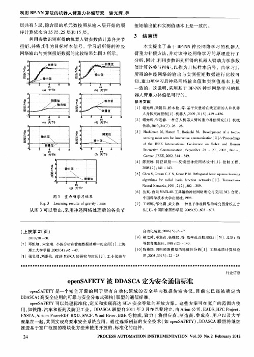
输 出值
2 0 ( ):4 0 5 2 1 1—13 4.
\
… …一 …… … ’ \ 测 量值
输 出值
龟
测 量值 / ,
o t e EE f h I E I t r n t n C n e e c o Ro o a d nea ai a ol o frn e n b t n Hu n ma
I tr c ie n e a t Co v mmu i ai n,S p e e 2 — 2 n c to e tmb r 5 7,2 0 0 2,B r n, el i
安装确认IQ(中英文)

EXECUTION APPROVAL SIGNATURES批准执行签名The signatures below indicate approval of this protocol and its attachments and indicate that it is ready for execution. Any changes or modifications to the intent or the acceptance criteria of this protocol, following approval, requires the generation of an amendment which must be approved prior to execution.下面的签名表示批准本文件及其附件,且表明已经为执行作好了准备。
在批准后,对本文件的目的或验收标准进行的任何改变或修正都必须起改善的作用,在执行以前就必须取得批准。
Contents目录1.0 SCOPE 范围 (4)2.0PURPOSE 目的 (4)3.0BACKGROUND- 背景 (4)4.0INTRODUCTION 介绍 (4)5.0REFERENCES 参考书目 (5)6.0 RESPONSIBLE PARTIES AND RESPONSIBILITIES 责任方及其责任 (6)7.0SYSTEM DESCRIPTION 系统说明 (7)G ENERAL D ESCRIPTION 总说明 (7)P RETREATMENT U NIT 预处理单元 (8)R EVERSE O SMOSIS (RO)S YSTEM 反渗透(RO)系统 (9)M IXED B ED S YSTEM 混床系统 (9)M ONITOR AND C ONTROL S YSTEM 监视和控制系统 (10)8.0TESTING PROCEDURES 检验程序 (10)9.0ACCEPTANCE CRITERIA 验收标准 (12)A TTACHMENT 1-V ALIDATION T EST E QUIPMENT AND M ATERIALS 附件1—验证测试设备和材料 (13)A TTACHMENT 2-S PECIFICATION AND P URCHASE O RDER V ERIFICATION 附件2—规范和采购单确认 (14)A TTACHMENT 3-E NGINEERING D RAWING L IST 附件3—工程图纸清单 (15)A TTACHMENT 4-S TANDARD O PERATING P ROCEDURES L IST 附件4—标准操作程序清单 (16)A TTACHMENT 5-O PERATION AND M AINTENANCE M ANUAL L IST 附件5—操作和维护手册清单 (17)A TTACHMENT 6-M AJOR C OMPONENT L ABELING L IST 附件6—主要部件标签清单 (18)A TTACHMENT 7-C RITICAL I NSTRUMENT L IST 附件7—关键仪器清单 (19)A TTACHMENT 8-N ON-C RITICAL I NSTRUMENT L IST 附件8—非关键仪器清单 (20)A TTACHMENT 9-S PARE P ARTS L IST 附件9—备件清单 (21)A TTACHMENT 10-I NSTALLATION P ROCEDURES V ERIFICATION D ATA S HEET 附件10—安装程序确认数据表 (22)A TTACHMENT 11-U TILITY D ATA S HEET:E LECTRICAL 附件11—公用工程数据表:电 (23)A TTACHMENT 12--U TILITY D ATA S HEET:C OMPRESSED A IR 附件12—公用工程数据表:压缩空气 (24)A TTACHMENT 13--U TILITY D ATA S HEET:C ITY W ATER 附件13—公用工程数据表:自来水 (25)A TTACHMENT 14--U TILITY D ATA S HEET:W ASTE/D RAIN 附件14—公用工程数据表:废水/排水 (26)A TTACHMENT 15--PW D ISTRIBUTION L OOP D ATA S HEET 附件15—纯化水循环回路数据表 (27)A TTACHMENT 16–C HEMICAL T ANK AND D OSING P UMP D ATA S HEET 附件16—化学罐和计量泵数据表 (28)A TTACHMENT 17–S AND F ILTER D ATA S HEET 附件17—砂滤过滤器表 (29)A TTACHMENT 18--H EAT E XCHANGER D ATA S HEET (P RETREATMENT)附件18—热交换器数据表(预处理) (30)A TTACHMENT 19--A CTIVATED C ARBON F ILTER D ATA S HEET 附件19—活性炭过滤器数据表 (31)A TTACHMENT 20–S TERILIZATION P UMP D ATA S HEET 附件20—灭菌循环泵数据表 (32)A TTACHMENT 21--S OFTENER D ATA S HEET 附件21—软化器数据表 (33)A TTACHMENT 22--P RECISION F ILTER D ATA S HEET 附件22—精密过滤器数据表 (34)A TTACHMENT 23–B OOSTER P UMPS D ATA S HEET 附件23—增压泵数据表 (35)A TTACHMENT 24–RO C LEANING T ANK AND P UMP D ATA S HEET 附件24–RO药洗箱和泵数据表 (36)A TTACHMENT 25--R EVERSE O SMOSIS (RO)S YSTEM D ATA S HEET 附件25--反渗透(RO)系统数据表 (37)A TTACHMENT 26--I NTERMEDIATE S TORAGE T ANK D ATA S HEET 附件26--中间储罐数据表 (38)A TTACHMENT 27--M IXED B ED S YSTEM D ATA S HEET 附件27--混床系统数据表 (39)A TTACHMENT 28–M IXED B ED R EGENERATION T ANKS AND P UMPS D ATA S HEET 附件28–混床再生酸碱箱和泵数据表 (40)A TTACHMENT 29--M ICRO F ILTER D ATA S HEET 附件29—微滤器数据表 (41)A TTACHMENT 30--4T D EIONIZED W ATER S TORAGE T ANK D ATA S HEET 附件30–4吨去离子水储罐数据表 (42)A TTACHMENT 31--1T PW S TORAGE T ANK D ATA S HEET 附件31–1吨纯水储罐数据表 (43)A TTACHMENT 32-S TORAGE T ANK S PRAY B ALL D ATA S HEET 附件32–储罐喷淋球数据表 (44)A TTACHMENT 33--UV S ANITIZER U NIT D ATA S HEET 附件33--UV灭菌器数据表 (45)A TTACHMENT 34–R ESIN T ANK D ATA S HEET 附件34—核子级树脂罐表 (46)A TTACHMENT 35--2T PW S TORAGE T ANK D ATA S HEET 附件35–2吨纯水储罐数据表 (47)A TTACHMENT 36--300L PW S TORAGE T ANK D ATA S HEET 附件36–300L纯水储罐数据表 (48)A TTACHMENT 37--H EAT E XCHANGER L OOP B UFFER T ANK D ATA S HEET 附件37–热交换器循环缓冲罐数据表 (49)A TTACHMENT 38--V ALVE D ATA S HEET 附件38--阀门数据表 (50)A TTACHMENT 39-S AMPLE P ORTS D ATA S HEETS 附件39-取样口数据表 (51)A TTACHMENT 40-S IGNATURE V ERIFICATION L IST 附件40-签名确认清单 (52)A TTACHMENT 41--P ROTOCOL D EVIATION L OG 附件41--文件偏差日志 (53)A TTACHMENT 42--P ROTOCOL D EVIATION R ECORD 附件42--文件偏差记录 (54)A TTACHMENT 43--P ROTOCOL E XECUTION A PPROVAL S IGNATURES D ATA S HEET 附件43--文件执行批准签名数据表 (55)1.0 SCOPE范围This Installation Qualification (IQ) study will be performed on the Purified Water (PW) System located in YUNG SHIN PHARM.IND.(KS)CO.,LTD.本次安装鉴定 (IQ)将会在位于永信药品工业(昆山)有限公司的纯化水(PW)系统上实施。
安全门和安全磁感应传感器模块(EN 60204-1、EN 292-1 -2、EN 418和EN108

•Safety Category 4, Performance Level e, according to EN 13849-1•Safety Category 4 according to EN 954-1•Category 0 Emergency Stop (EN 60204-1)•Input type: 1 NO + 1 NC•2 x 6 A NO safety outputs (NSC02D)•3 x 6 A NO safety outputs and 1 x 6 A NC auxiliary output (NSC13D)•Automatic / manual or monitored manual reset •Single / double channel operations•LED indication for outputs status and power supply ON •Connection by fixed or detachable terminals•For mounting on DIN-rail in accordance with DIN/EN 50022•22.5 mm Euronorm housingProduct De s crip t ionSafety gate and safety magnetic sensor modules according to EN 60204-1, EN 292-1/-2, EN 418 and EN1088.This family of safety module in Safety Category 4,Performance Level e,includes fixed screw and detachable screw as well as automatic / manual or monitored manual restart versions.Safety ModulesSafety Gate and Safety Magnetic Sensor Types NSC02D, NSC13DTime SpecificationScrew, fixed Type SelectionAuxiliary outputsSafety outputs 2 NO 2 NO 2 NO 2 NO 1 NC 3 NO 1 NC 3 NO 1 NC 3 NO 1 NC3 NOInput SpecificationNSC02D, NSC13DOutput SpecificationSupply SpecificationsGeneral SpecificationMode of OperationThe safety modules NSC02D and NSC13D monitor both mechanical switches and safety magnetic sensors (1NO + 1 NC contact outputs),according to 98/37/CE Machinery Directive.If the unit is correctly supplied and the input terminals are operated (S1 closed and S2open, i.e. safety gate closed),the module is enabled to close the safety outputs and the external contactors can be energized. When the input terminals are released (S1open and S2 closed, i.e.safety gate open) the module is not enabled to close the safety outputs and the external contactors can not be energized.Automatic STARTProvided that the terminals X1 and X2 (NSC02...A) or S33and S34 (NSC13...A) are connected, the safety outputs close and the auxiliary output opens (NSC13...A) as soon as both S1 and S2 switches operate. The relevant CH1and CH2 LED turn on.Releasing even one input contact (S1 and/or S2) forces immediately the safety outputs to open and the auxiliary output (NSC13...A)to close.A new operating cycle is possible only after releasing both input contacts and then operating them again.Manual STARTProvided that S1 switch isclosed and S2 is open, the safety outputs close and the auxiliary output opens (NSC13...A) as soon as the NO START pushbutton is pushed [connecting X1 and X2 (NSC02...A) or S33 and S34 (NSC13...A)]A new operating cycle is possible only after releasing both input contacts, closing them again and pushing the START button.Monitored manual START The monitored manual START versions (NSC...C) work as described in the previous paragraph (M anual START)except for a minimum delay of 500 ms from the operated status of the input contacts (S1 closed, S2 open) to thepushing of the START button. If the input terminals get operated with the START switch already closed, the safety outputs don’t close and the auxiliary doesn’t open (NSC13...C): it is necessary to release the START button and the input contacts before starting a new cycle, then operate the input contacts and finally,after at least 500 ms, operate the START button.So if the NO START button gets welded, the outputs don’t close anymore. Note.NSC02D and NSC13D can be also used as Emergency Stop modules, ensuring up to Safety Category 3.NSC02D, NSC13D Operational DiagramWiring DiagramsNSC02D, NSC13DWiring Diagrams (cont.)Dimensions。
MK_希尔顿酒店设计规范-GS13防火和人身安全系统

防火人身安全系统GS 13 防火/人身安全系统指南引言GS 13 总述GS 13.1 释义GS 13.2 防火报警系统GS 13.3 防火报警系统组件GS 13.4 水管系统和水带卷筒站GS 13.5 洒水灭火系统GS 13.6 手提防火设备GS 13.7 防火程序和撤离标记GS 13.8 事故照明和出口照明GS 13.9 厨房和配餐室GS 13.10 楼梯压力输送GS 13.11 除烟GS 13.12 机械排风和空调GS 13.13 限制火/烟扩散GS 13.14 灭火器GS 13.15 隔离和出口GS 13.16 电梯GS 13.17 事故电源引言Hilton International (希尔顿国际)做为业主、合作者和高标准国际酒店的管理公司深知:必须为员工和客人提供安全、健康的环境。
人身安全应该是酒店设计开发过程的有机组成部分。
因此,Hilton International 要求安装如酒店规划指南部分所述的人身安全防备。
完成Hilton International 安全要求在设计过程的各个阶段有Hilton International技术人员在现场。
指南主要是指导防火和人身安全专业人员对国际认可和接受的标准,按照灵活、专业判断和常识进行调节。
应结合区域已有的防火规范阅读指南,如果已确定了高标准,应该遵守高标准。
为了达到更高的安全标准,Hilton International 要求安装覆盖酒店所有区域的全自动监测和抑制系统,即使当地规范没有要求此系统。
GS 13 总述在指南中设置的设备是为了防火安全的不同方面,主要目的是:*一旦发生火情,应有一套供人员撤离的令人满意的标准。
*禁止使用能使火情扩散的内衬。
*一旦发生火情,保证酒店安定;保证在酒店和临近建筑物间有足够的防火隔离;防止酒店隐蔽处看不到的火、烟扩散。
*外墙和房顶应适当限制外部围墙的火情扩散,防止来自其它建筑物的火情扩散。
*确保到酒店的防火设施入口畅通,防备器械应有助于消防人员在酒店内和酒店周围救人。
api623-2013英文版

api623-2013英文版API 623-2013 is an international standard that provides guidelines and requirements for the design, manufacture, testing, and documentation of steel valve pressure testing and inspection. It covers various types of valves, including gate, globe, check, float, and plug valves.The standard focuses on the following aspects:1. Pressure testing: API 623-2013 describes the procedures and requirements for pressure testing the valves to ensure their structural integrity and leak-tightness. It covers both hydrostatic and pneumatic testing methods.2. Inspection and testing: The standard specifies the inspection and testing requirements for valves, including visual inspection, dimensional checks, mechanical testing, and non-destructive examination techniques.3. Documentation: API 623-2013 emphasizes the importance of proper documentation in the valve manufacturing process. It provides guidelines for documentation requirements, such as material certifications, test reports, and traceability of components.4. Quality control: The standard highlights the importance of a comprehensive quality control program in valve manufacturing. It includes requirements for quality control procedures, personnel qualifications, and calibration of equipment used in testing and inspection.Overall, API 623-2013 aims to ensure the performance and reliability of steel valves by providing guidelines for their design, manufacturing, testing, and documentation. Compliance with this standard helps ensure that valves meet industry requirements and standards.。
布斯奇建筑集成系统(BIS)安全与安全文件说明书

party system: Facility Management (planning and costs), ERP (SAP, Time & Attendance), SCADA
Workstation
Workstation
Workstation
Workstation
fire & life safety
▶ Easily access post-event reporting and forensic analysis to help in future process optimization
▶ Protect your investment by being open, flexible and always backward compatible for maximum return on investment
MS-GB-en-01_F01U560768_01.indd 1-2
When designing comprehensive security and safety systems, both planners and building operators often choose to mix and match fire protection, public address, access control, video surveillance and management systems from multiple vendors.
▶ Connect and integrate an extensive range of Bosch and 3rd party security and safety products for maximum design flexibility
将安全保护任务简单化
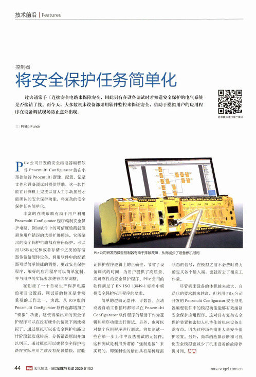
技术前沿I Features控制器将安全保护任务简单化过去通常手工迮接安全电路来保障安全,W 此只有在设侪调试吋才知进安全保护的电气系统 足否接错了线。
而今天,大多数机床设济都采用软件监控来保证安全,借助于模拟)丨】户的应州程 序在设侪调试现场防止意外出现。
更多精彩请扫描二维码文丨 Philip Fu n ckPilz 公司研发的微型控制器有助于排除故障,从而减少了设备停机时间Pi l z 公司开发的安全继电器编程软件 Pnozmulti Configurator 能在小型控制器Pnozmulti 新建、配置、记录 文件和设备调试时提供帮助。
这一软件 能在计算机上完成以前人工手动接线才 能确认的安全保护功能,将复杂的安全 保护任务简单化。
丰富的在线帮助有助于用户利用Pnozmulti Configurator 程序编制安全保护电路。
例如软件中的可信度检测就能 避免用户错误的选择扩展模块。
它所编 出的安全保护电路都有密码保护,可以 用U S B 记忆棒或者存储卡之类的存储 器传输给硬件设备。
利用软件中的配置 器可以简单快捷的调整、更改安全保护 程序,编好的应用程序可以简单复制, 并与用户的实际要求进行匹配调整。
在创建了一个自动生产保护电路 的项目设置后,调试前的检查是非常 重要的工作之一。
为此,从10.9版的Pnozmulti Configurator 软件起都增加了“模拟”功能。
这使得编出来的安全保 护程序可以在没有硬件的情况下离线模 拟了。
通过模拟可以在安全保护电路设 计阶段就发现错误,分析错误原因并加 以纠正。
通过模拟可以确保安全保护电 路在实际应用之前没有配置错误,应验证保护程序逻辑上的正确性,节省了设 备调试的时间,为用户提供了高质量、 高可靠性的安全保护程序。
P ilz 公司的 软件满足了 EN ISO 13849-1标准中模 拟安全保护应用程序的要求。
简单的逻辑元器件、计数器、点动 或者自动工作循环都可以在PnozmultiC onfigurator 软件程序的帮助下作为逻辑和顺序功能进行测试。
openSAFETY基础引导(一)

openSAFETY基础引导(一)一、适用于所有现场总线由ESPG 引入的openSAFETY,是世界上第一个100%开源的安全协议。
它不仅在法律层面上是开放的,在技术层面上也是。
由于该协议独立于总线,openSAFETY 可以应用于任何现场总线和工业以太网的方案中,甚至用于特殊定制的协议方案中。
亮点openSAFETY 是第一个开源、独立于总线的安全标准,适用于所有工业以太网方案。
对于在任何数据传输协议上openSAFETY 的实施,EPSG 都将提供积极支持,同时也提供认证和一致性测试。
该经过TÜV 认证的协议栈确保了对该技术的投资是绝对安全的。
一个统一标准,适用于所有现场总线从站间直通信(cross communication)使生产力最大化研发、维护时间进一步减少自动的安全参数化完全符合机器的安全模块化思想完整的开源解决方案最稳健的IEC 61508 SIL3 通信方案无风险,TÜV 认证的一致性测验完全适用背板总线传输层和应用层标准OSI 模型是当今应用最普遍的数据传输协议的模型,它是层级式结构的,有7 层。
根据规则,每层处理相应任务。
这里最基础的、最底层的是物理层和数据链路层,也可以将二者一同叫做物理层。
它们定义了物理接口的传输媒介,也提供发送端和接受端之间是否建立了连接的检测。
以太网仅明确了这两个底层。
第三、四层也被叫做传输层,负责处理时序、数据传输的逻辑顺序以及数据的应用属性(data attribution to applications)。
这四层包含的都是面向传输的服务,所做的只是建立应用数据的传输媒介。
应用数据本身属于上层。
上层包括会话层和表示层。
这二者经常与应用层合在一组,因为程序都是直接访问他们三者的。
会话层管理不同应用程序之间数据交换的组织方式和同步。
比如,如果一个连接被中断,该层的服务便确保在连接再次建立之后,通信会在断点处继续。
工业企业自动化系统的发展与变化
工业企业自动化系统的发展与变化发表时间:2014-09-04T15:58:17.750Z 来源:《科学与技术》2014年第7期下供稿作者:关双萍[导读] 信息时代成为时下的主角,从而要求企业要从海量的信息之中,寻找适合企业的商机,进行企业的发展动力。
浦北县浦能水电有限公司关双萍目前,我国工业企业已经进入了自动化时代,发展至广义、扩展、综合自动化,通过全面分析、积累和掌握生产线、设备的情况,从而对相应的工厂、工作车间、及相应的设备进行数字信息化了解、学习、最终掌握它们的特点,从而通过控制策略及动作,改善和提升工厂的形态,及车间的生产效率,从而实现生产自动化与现代管理的完美融合,使企业的走向综合管理时代,也增加了市场竟争力。
1 工业企业自动化系统的发展60 年代以经典控制论为根本,采用常规自动调节仪表进行自动化设备升级,由于控制系统简单,一直表现出平稳的发展态势。
60 至80 年现代控制理论成为过去式,分散式成为新基础,自动化得到进一步的发展,自动化进入了高品质,高产出,低损耗。
90 年控制理论被综合化理论所替代,交叉学科成为主场。
控制、信息、系统、智能论等。
新技术以计算机网络为核心的系统。
从而广义自理论开始形成,工厂、企业、管理自动化都可以称之为广义自动化,最终目的都是完成综合化指令。
自动化时代的带来,让人们的思想得以转变。
传统的自动化是生产自动化并没有人员的参与,而综合及广义自动化却是要求人和自动的完美统一。
从而让企业内部相关联的各环节进行统一,而不是以传统的自动化模式进行运营,而是通过综合及广义自动化模式把资金、运营、供需、服务品质等连接起来。
通过信息进行企业决策,从而完成各项指标,是企业信息的重要意义。
信息时代成为时下的主角,从而要求企业要从海量的信息之中,寻找适合企业的商机,进行企业的发展动力。
2 广义自动化系统为企业提供设备信息集成信息集成存有优势,同时也存在风险,由于信息系统复杂化,在急某种信息的时候,就会增加难度。
FC18_操作手册
JB-TGZL-FC18R型火灾报警控制器(联动型)操作说明书目录第一章系统简介 (3)1.特点 (3)2.性能参数 (4)3.外形尺寸 (5)4.兼容设备目录 (5)5.系统结构 (6)第二章安装 (8)1.安装过程 (8)2.接线图 (9)3.拨码开关设置 (13)第三章操作 (14)1.界面显示 (14)2.液晶窗口显示 (16)3.用户级别 (18)3.1登录 (19)3.2退出 (19)4.状态类型 (20)5.火警事件处理 (22)6.故障事件处理 (23)7.监管事件处理 (24)8.启动/反馈事件处理 (25)9.实时事件查询 (26)10.设备属性查询 (27)11.历史记录查询 (28)12.如何进行屏蔽/开放 (29)13.如何进行启动/停止 (30)14.如何进行测试/移动测试 (31)15.如何进行定位测试/定位恢复 (32)16.如何设置蜂鸣器音量 (33)17.如何设置登录时间 (34)18.如何设置移动测试时间 (35)19.如何设置LCD关闭时间 (36)20.如何设置时间 (37)21.如何进行系统检测 (38)22.如何保存配置 (39)23.如何修改参数 (40)24.如何新建/查看联动关系 (41)25.如何编辑/删除联动关系 (42)26.如何进行组分配/FRT分配 (44)27.如何查看帮助信息 (45)28.如何操作联动盘 (45)29.如何打开/关闭打印机 (46)30.如何替换设备 (48)页码:1/60JB-TGZL-FC18R型火灾报警控制器(联动型)操作说明书第四章维护 (49)1.日常检查 (49)2.应急故障处理 (49)3.可替代元件 (51)附录1 可编辑参数表 (52)附录2 设备可操作项一览表 (55)附录3 设备分组表 (57)附录4 联动关系编写规则 (58)附录5 输入法 (59)附录6 方便快捷的工程调试方法 (60)附录7 名词解释 (60)页码:2/60JB-TGZL-FC18R型火灾报警控制器(联动型)操作说明书第一章系统简介JB-TGZL-FC18R系列控制器包括:-FC1860型火灾报警控制器(联动型)1. 特点-符合国家标准GB4717-2005《火灾报警控制器》和GB16806-2006《消防联动控制系统》。
- 1、下载文档前请自行甄别文档内容的完整性,平台不提供额外的编辑、内容补充、找答案等附加服务。
- 2、"仅部分预览"的文档,不可在线预览部分如存在完整性等问题,可反馈申请退款(可完整预览的文档不适用该条件!)。
- 3、如文档侵犯您的权益,请联系客服反馈,我们会尽快为您处理(人工客服工作时间:9:00-18:30)。
POWERLINK
SERCOS
PROFINET
One standard for all networks
EtherNet/IP
POWERLINK
SERCOS
PROFINET
One standard for all networks
EtherNet/IP
POWERLINK
SERCOS
• Fastest reaction time • Smaller footprint of machine
Elimination of Setup Errors
Benefit
3
Speed Limit
Hard-wired safety
Integrated safety
500ms
• Significant risk of errors during maintenance
openSAFETY
The open safety standard for all communication protocols
What does Safety normally look like?
• Safety Relays within the cabinet • Safety application by discrete wiring
Servo PLC I/O
Additional DI/DO module Extra wiring of safe sensors Extra wiring required to control safe actuators
Safety Relays
Timer Relays
• Intelligent safe motion functions
Safety market overview
• Available Safety Protocols
– – – – ProfiSafe CIPSafety Safety EtherCAT Safety Net p is limited to Profibus and Profinet is limited to Rockwell protocols and SERCOS is limited to EtherCAT is a proprietary protocol from PILZ
PROFINET
openSAFETY is open and independent
• The world’s first 100% open safety protocol • Totally independent from technical and legal aspects • Supported by the international user organization EPSG
• These protocols are proprietary or limited to a certain Fieldbus! • These technologies are NOT compatible with each other!
Safety market overview
• Available Safety Protocols
PROFINET
One standard for all networks
EtherNetINET
One standard for all networks
EtherNet/IP
POWERLINK
SERCOS
PROFINET
One standard for all networks
– – – – – ProfiSafe CIPSafety Safety EtherCAT Safety Net p openSAFETY is limited to Profibus and Profinet is limited to Rockwell protocols and SERCOS is limited to EtherCAT is a proprietary protocol from PILZ is open and available for any fieldbus
Black channel mechanism
Any fieldbus POWERLINK Modbus SERCOS EtherNet/IP PROFINET
Black channel mechanism
Any fieldbus POWERLINK Modbus SERCOS EtherNet/IP PROFINET
Safety market overview
• Available Safety Protocols
– – – – ProfiSafe CIPSafety Safety EtherCAT Safety Net p is limited to Profibus and Profinet is limited to Rockwell protocols and SERCOS is limited to EtherCAT is a proprietary protocol from PILZ
Safety Relays
Servo
PLC
I/O
What does Safety normally look like?
• Safety Relays within the cabinet • Safety application by discrete wiring
Servo PLC I/O
Additional DI/DO module
EtherNet/IP
POWERLINK
SERCOS
PROFINET
One standard for all networks
EtherNet/IP
POWERLINK
SERCOS
PROFINET
One standard for all networks
EtherNet/IP
POWERLINK
SERCOS
• Electronic data sheet • Maintenance logging • Password protection
Intelligent Safety Features
Benefit
4
Hard-wired safety
Integrated safety
• Only Safe Torque Off
• Flexible • Decentralized • Certified
PLC
I/O
I/O
Reduced Wiring
Benefit
1
Hard-wired safety
Integrated safety
Standard DI
Safety Relais
• Additional Wiring • Failure of standard I/O’s can affect safety
Safety Relays
Speed Monitor
Extra speed monitor for safe motion control functions
What does Safety normally look like?
• Safety Relays within the cabinet • Safety application by discrete wiring
Safety Relays
What does Safety normally look like?
• Safety Relays within the cabinet • Safety application by discrete wiring
Servo PLC I/O
Additional DI/DO module Extra wiring of safe sensors
• These protocols are proprietary or limited to a certain Fieldbus!
Safety market overview
• Available Safety Protocols
– – – – ProfiSafe CIPSafety Safety EtherCAT Safety Net p is limited to Profibus and Profinet is limited to Rockwell protocols and SERCOS is limited to EtherCAT is a proprietary protocol from PILZ
Errors and preventive/corrective measures
• No faults go undetected!
Safety measures according to IEC 61784-3
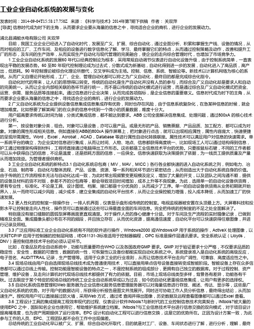
Frame structure
• The frame consists of two sub frames and is able to transport data up to 254 bytes of payload data
Black channel mechanism
Black channel mechanism
Any fieldbus POWERLINK Modbus SERCOS EtherNet/IP PROFINET
Black channel mechanism
Any fieldbus POWERLINK Modbus SERCOS EtherNet/IP PROFINET