OX6580A-LZ中文资料
微型计算机原理及应用
一、单选题(共15 道试题,共30 分。
)V 1. hold命令的作用是()。
A. 给图形添加栅格B. 图形窗口保持C. 关闭图形D. 去除图形栅格2. 将系统传递函数形式变换为零极点形式的命令是()。
A. tf2zpB. ss2tfC. ss2zpD. zp2tf3. i=2; a=2i;b=2*i;c=2*sqrt(-1);程序执行后;a, b, c的值分别是()。
A. a=4,b=4,c=2.0000iB. a=4,b=2.0000i, c=2.0000iC. a=2.0000i, b=4,c=2.0000iD. a=2.0000i,b=2.0000i,c=2.0000i4. 数值积分法中,其计算精度p=2的算法是()。
A. 欧拉法B. 梯形法C. 四阶—龙格库塔法D. 以上都不是5. 绘制控制系统根轨迹的命令是()。
A. stepB. pzmapC. rlocusD. sgrid6. figure命令的作用是()。
A. 绘图B. 关闭当图形行窗口C. 打开新的图形窗口D. 循环7. 用round函数四舍五入对数组[2.48 6.39 3.93 8.52]取整,结果为()。
A. [2 6 3 8]B. [2 6 4 8]C. [2 6 4 9]D. [3 7 4 9]8. 某系统传递函数为G,语句step(G)的执行结果为()。
A. 绘制系统的根轨迹图B. 绘制系统的单位脉冲响应曲线C. 绘制系统的奈氏曲线D. 绘制系统的单位阶跃响应曲线9. CAD软件中我们一般都用()单位来做图以达到最佳的效果。
A. 米B. 厘米C. 毫米D. 分米10. 在CAD网络系统中,以下说法不正确的是()。
A. 设计资料可以共享B. 硬件可以共享C. 电脑文件可以共享D. 可以方便管理设计进度11. 计算机辅助设计的英文缩写是()。
A. CADB. CAMC. CAED. CAT12. 给图形添加栅格的命令是()。
cpu
架构和执行单元内部的资料线路是 32 位元
时脉速度:
5 MHz
7 MHz
8 MHz
[编辑]i960 或 80960
推出于 1988年 4月5日
类似 RISC 的 32 位元 架构
主要地使用在嵌入式系统
Evolved from the capability 处理器 developed for the BiiN joint venture with Siemens
80188
80286
1985 80386DX
1988 80386SX i960
1989 80376
80486DX i860
1990 80386SL
1991 80486SX
1992 80486DX2
80486SL
1993 Pentium
1994 i386EX
80486DX4
1995 Pentium Pro
1997 Pentium MMX Pentium II
1998 Celeron
Pentium II Xeon
10.2 移動版
10.2.1 Intel Core 2 Duo
11 64 位元处理器: Itanium系列
11.1 Itanium
11.2 Itanium 2
12 64 位元处理器:Intel 64 的 Nehalem 架构
12.1 Intel Pentium
12.2 Core i3
2.1 Intel 4004: 第一个单芯片 µP
2.2 4040
2.3 8008
2.4 8080
ECCM5A6FD-50-19.6608M中文资料(Ecliptek)中文数据手册「EasyDatasheet - 矽搜」

ECLIPTEK CORP.
CRYSTAL
ECCM5A
REEL
R
2.5分钟
M
1.5分钟
S
10分钟
N
O
P
50分钟 20.2 MIN 13±.2
T
U
V
22.4 MAX 360 MAX 16.4+2-0
Q
40分钟 数量/卷 1,000
标记规格
*兼容于EIA-481A
Line 1: E XX.XX Line 2: XX Y ZZ
CRYSTAL
ECCM5A
CERAMIC
CR30
.
01/08
36 规格如有更改,恕不另行通知.
芯片中文手册,看全文,戳
频率容限( 25°C) 4=±15ppm, 5=±30ppm, 6=±50ppm
频率稳定度
D=±20ppm, E=±30ppm, F=±50ppm
工作温度范围
按照表1
芯片中文手册,看全文,戳
ECCM5列A
•符合RoHS(无铅) •微型4片陶瓷
SMD封装 •AT切割 •紧公差/稳定性 •频率为35.328MHz可用 •磁带和卷轴可用
ECCM5A
H 1.0 L 6.0 W 3.5
水晶
NOTES
______________________________________________________________________________________________________________________________________________________________________________________________ ______________________________________________________________________________________________________________________________________________________________________________________________ ______________________________________________________________________________________________________________________________________________________________________________________________ ______________________________________________________________________________________________________________________________________________________________________________________________ ______________________________________________________________________________________________________________________________________________________________________________________________
WD西部数据硬盘分类
西部数据 WD 驱动器分类西部数据是最早的硬盘驱动器和驱动器部件的生产商。
因此, WD 在设计和生产用于硬盘驱动器的系统控制器方面居于领先地位。
习惯上根据系统控制器的应用电路架构来对WD 硬盘驱动器划代。
1. 产品的命名通过名字可以识别驱动器的系列和容量。
WD 的第一代IDE 驱动器叫做Centaur ,有四个系列。
这四个系列的型号见下表:例如: WD93048A ,WD95044A 第二代WD 硬盘驱动器有50个系列: 例如: WDAC2120,WDAC35100A ,WDE4360,PhD2100,WDCU140从 WD205AA 系列20.5 GB 的驱动器开始,使用象今天这样的一种方式编号:1.WDWestern Digital 2.容量200,0GB (最大999,9GB ) 3.转速字母A - E分配给EIDE:A - 5400 rpm(WD 鱼子酱5400)B - 7200 rpm(WD 鱼子酱7200)C - 10'000 rmpD - 4500 rpm(WD Spartan)E - 5400 rpm(WD Protege)字母F - Z分配给SCSI和特种硬盘驱动器:F - 10'000 rmp,2Mb缓存G - 10'000 rpm,8Mb缓存H - 10'000 rpm,4Mb缓存J - 7200 rpm,8Mb缓寸K - 7200 rpm(performance)L - 7200 rpm(液态轴承)M - 5400 rpm(液态轴承)N - 5400 rpm(WD-Protege-液态轴承)P - 7200 rpm,8Mb缓存(液态轴承)Q-Z - 保留4.接口字母A - E分配给EIDE:A - ATA66B - ATA100C - FireWireD - Serial ATAE - ATA133字母F-V分配给SCSI和特种硬盘驱动器F - Fibre ChannelG - Ultra2(68 针)H - Ultra2(80 针)J - Ultra160(68 针)K - Ultra160(80 针)L - Ultra3(68 针)M - Ultra3(80 针)N - UltraSE(50 针)P-V - 保留A/V 家用,使用字母W-ZW - A/V家用X-Z - 保留5.客户标识00 – Generic(通用公司)10 – DEC(DEC公司)11 - WD Protege OEM12 – Intel(Inter公司)18 – Dell(Dell公司)23 – IBM(IBM公司)25 – Toshiba(东芝公司)28 – Microsoft(微软公司)32 - Reseller35 - WD Spartan40 – Apple (苹果公司)44 - WD protege 其他60 – Compac (康柏公司)80 – Motorola (摩托罗拉公司)90 - 零售95 - Tektronix99 – Boeing (波音公司)6.属系标识硬盘驱动器工程命名的通俗名称。
XP错误代码大全

0x0000000A:IRQL_NOT_LESS_OR_EQUAL故障分析0x0000000A 错误表示在内核模式中存在以过高的进程内部请求级别(IRQL)访问其没有权限访问的内存地址。
这个错误一般是因为硬件设备的驱动程序存在BUG,某些软件或硬件与Windows不兼容引起的。
如果遇到0x0000000A错误,建议尝试以“最后一次正确的配置”方式启动 Windows,并检查一下最近有没有安装或升级过任何系统更新、硬件设备的驱动程序、BIOS、Firmware及应用软件等。
如果有的话,请将最近更新过的应用软件及硬件设备逐一卸载、恢复到之前可以稳定运行的版本,看看问题能否解决。
错误名称0x0000001A:MEMORY_MANAGEMENT故障分析0x0000001A 错误表示内存管理遇到了问题。
这个错误一般是因为硬件设备的故障引起的。
如果遇到0x0000001A错误,建议检查一下最近有没有安装过新的硬件设备或驱动程序。
如果有的话,请将最近安装过的硬件设备或驱动程序逐一卸载,看看问题能否解决。
另外,如果是在安装Windows时遇到0x0000001A错误,请检查一下计算机的内存容量及规格是否符合Windows 的要求。
参考资料关于0x0000001A错误,可以参考Microsoft知识库文章KB282504:/kb/282504/zh-cn(/kb/282504/zh-cn)错误名称0x0000001E:KMODE_EXCEPTION_NOT_HANDLED故障分析0x0000001E 错误表示Windows检测到一个非法的或未知的进程指令。
这个错误一般是因为内存发生故障引起的,或者与0x0000000A错误相似,表示在内核模式中存在以过高的进程内部请求级别(IRQL)访问其没有权限访问的内存地址。
如果遇到0x0000001E错误,建议首先检查一下软件及硬件兼容性,看看最近有没有安装过新的应用软件、硬件设备或驱动程序。
25AA1024中文资料

7
pF TA = 25°C, CLK = 1.0 MHz,
VCC = 5.0V (Note)
10
mA VCC = 5.5V; FCLK = 20.0 MHz;
SO = Open
5
mA VCC = 2.5V; FCLK = 10.0 MHz;
SO = Open
7
mA VCC = 5.5V
5
mA VCC = 2.5V
† NOTICE: Stresses above those listed under “Absolute Maximum Ratings” may cause permanent damage to the device. This is a stress rating only and functional operation of the device at those or any other conditions above those indicated in the operational listings of this specification is not implied. Exposure to maximum rating conditions for an extended period of time may affect device reliability.
ANTEC NSK 6000, 6580 and 6580 机箱 说明书
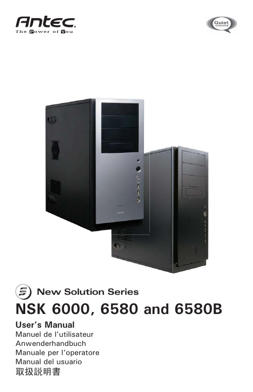
New Solution Series User’s ManualManuel de l’utilisateur AnwenderhandbuchManuale per l’operatoreManual del usuarioAt Antec, we continually refine and improve our products to ensure the highest quality. It’s possible that your new case will differ slightly from the descriptionsin this manual. This isn’t a problem; it’s simply an improvement. As of the date of publication, all features, descriptions, and illustrations in this manual are correct. DisclaimerThis manual is intended only as a guide for Antec’s Computer Enclosures. For more comprehensive instructions on installing the motherboard and peripherals, please refer to the user’s manuals that come with those components.New Solution Series User’s ManualNSK 6000, NSK 6580 and NSK6580BQuiet Super Mid Tower CaseThis case is designed to meet Intel’s Thermally Advantaged Chassis (TAC) design guide requirements.The Power SupplyWhile the NSK 6000 does not offer a PSU the NSK 6580 and the NSK6580B come with an EarthWatts 430 watt PSU. Universal input, active PFC single 80mm fan cooled power supply that follows the ATX12V version 2.2 specifications. This includes dual +12V output rails that deliver safer and more reliable output to your system’s components. Featuring higher energy efficiency, which reduces power consumption by up to 25%, saving you money on your electricity bill. EarthWatts power supplies have achieved 80 PLUS® Certification, the latest independent standard in power supply efficiency. In addition EarthWatts includes a variety of protective circuitry: OPP (over power protection), OVP (over voltage protection), and SCP (short circuit protection).The PSU comes with a main power switch. Make sure you turn the switch to the ON (I) position before you boot up the computer for the first time. Normally, you won’t need to switch to the OFF (O) position, since the PSU includes a soft on/off feature. This lets you turn the computer on and off by using the soft switch on the computer case. If the computer crashes and you can’t shut it down using the soft switch, you can switch the main power to the OFF (O) position to shut the system down. Then turn the switch back to the ON (I) position and reboot.Antec power supply models feature Power Factor Correction (PFC) circuitry in accordance with European standard regulation code EN61000-3-2. By altering the input current wave shape, PFC improves the power factor of the PSU. A better Power Factor increases energy efficiency, reduces heat, improves output voltage stability and prolongs the life of all equipment. The PSU’s high efficiency design and quiet fan deliver not only a cleaner but also a quieter operating environment. Setting UpAlthough care has been taken to prevent sharp edges in your Antec case, we strongly recommend taking your time and the appropriate care when working with it. Hurried or careless motion and use of excessive force, particularly when you are working in areas you cannot see clearly, are but a few examples of activity that should be avoided. Please use reasonable precaution.1.Place the case upright on a flat, stable surface. The power supply fan shouldbe at the back, facing you.2.Remove the screws from the right side panel. 3.There are two latches on the side panel. Slide the latches towards the front of the case and swing open the panel.4.Inside the case you should see the power supply, some wiring with markedconnectors (USB, PWR etc.), and installed I/O panel and a power cord.Installing the MotherboardThis manual does not cover CPU, RAM, or expansion card installation. Please consult the motherboard manual for specific mounting instructions andtroubleshooting.y the case down, with the open side facing up. The drive cages and powersupply should be visible.2.Make sure you have the appropriate I/O panel for the motherboard. If thepanel provided is not suitable for the motherboard, please contact themotherboard manufacturer for the correct I/O panel.3.Line up the motherboard with the standoff holes, and remember which holesare lined up. Not all motherboards will match with all the provided holes; this is normal, and won’t affect functionally.4. Remove the motherboard by lifting it up.5.Screw the brass standoffs into the threaded holes that line up with themotherboard. Do not overtighten the standoffs. Some standoffs may bepre-installed for your convenience.6. Place the motherboard on the brass standoffs.7.Screw in the motherboard to the standoffs with the provided Philips-headscrews.8. The motherboard is now installed.Connecting the Power and LEDThe power supply conforms to the ATX12V Version 2.2 standard. If themotherboard has a 20-pin power receptacle, detach the 4-pin attachment on the 24-pin power connector, see pictures 1 and 2. Before you connect the power supply to any devices, please consult the appropriate user manuals for the motherboard and other peripherals.1.Connect the 24-pin Main Power Connector and the 4-pin or 8-pin 12V con-nector to the motherboard as needed. If the mother-board uses a 20-pinconnector; detach the 4-pin attachment on the24-pin power connector (see pictures 1 and 2).Note : the detachable 4-pin section cannot be usedin place of a 4-pin +12V connector.2.Connect the Reset switch (labeled RESET SW) to the motherboard at the RST connector. Polarity(positive and negative) does not matter for switches.3.Power Switch (labeled POWER SW) connects to the PWR connector on themotherboard.4.Power LED (labeled POWER LED) connector is located behind the Resetconnector. For LEDs, colored wires are positive (+). White or black wires are negative (–). If the LED does not light up when the system is powered on, try reversing the connection. For more info on connecting LEDs to yourmotherboard, see your motherboard manual.5. Hard Drive LED (labeled H.D.D. LED) connects to the IDE connector.Picture 1Picture 2For 24-pin motherboards For 20-pin motherboardsConnecting the USB PortsYou will find a single 10-pin connector on a cable attached to the front USB ports. This is an Intel standard connector, which is keyed so that it can’t be accidentally, reversed as long as it is connected to a proper Intel standard motherboard header. Connect the 10-pin connector to the motherboard headers so that the blocked pin fits over the missing header pin.Note : Please check the motherboard manual for the USB header pin layout and make sure it matches the table below.Motherboard Pin LayoutConnecting the IEEE 1394 (FireWire®, i.Link®) PortYou will find a single 10-pin connector on a cable attached to the front IEEE 1394 connection. This is an Intel standard connector, which is keyed so that it can’t be accidentally reversed as long as it is connected to a proper Intel standard moth-erboard header. Connect the 10-pin connector to the motherboard header so that the blocked pin fits over the missing header pin.Note : Please check the motherboard manual for your IEEE 1394 header pin layout and make sure it matches the table below. If you intend to connect the front FireWire port to an IEEE 1394 add-on card that comes with an external-type IEEE 1394 connector, you will need a FireWire Internal Adapter. To order one, please visit Antec’s web store at /StoreFront.bok and search for part number 30031. This adapter will allow you to connect the front IEEE 1394 port to the external-type connector.Pin Assignment for Front Panel IEEE 1394 ConnectorPinSignal Names Pin Signal Names 1USB Power 12USB Power 23Negative Signal 14Negative Signal 25Positive Signal 16Positive Signal 27Ground 18Ground 29Key (No Connection)10Empty Pin12109PinSignal Names Pin Signal Names 1TPA+2TPA–3Ground 4Ground 5TPB+6TPB–7+12V (Fused)8+12V (Fused)9Key (No Pin)10Ground12109CONNECTING THE AUDIO PORTS (AC’97 and HDA)There is an Intel standard 10-pin AC’97 connector and an Intel 10-pin HDA (High Definition Audio) connector. You can connect either of them to your motherboard depending on the specification of the motherboard. See instruction below:NOTE: Please check your motherboard manual for your audio header pin layout and make sure it matches the table below. Even if your system supports both audio standards, you may only connect one connector not both.Pin Assignment for Audio Ports (HDA and AC’97)Locate the internal audio connectors from your motherboard or sound card. Consult your motherboard or sound card manual for the pin-out positions.3.5” Device InstallationThere is a 5.25” to 3.5” drive bay adapter installed inside the lowest 5.25” drive bay. Use this for the floppy drive or other external 3.5” device.1.Remove the lowest 5.25” drive bay cover that has a 3.5” drive bay cover init from the bezel.2. Remove the3.5” cover from it.3.Loosen the two screws that fasten the adapter to the drive bay and slide theadapter out through the front of the case.4. Mount the floppy drive or other external device into the adapter.5. Slide and fasten the adapter back into the case.6.Find a small 4-pin power connector on the power supply and connect it tothe male 4-pin power connector on the device.7. Reinstall the drive bay cover back to the bezel.There is a HDD cage under the external 5.25” drive bays for hard drives. Inside the cage there are five HDD bays. Each comes with an individual drive tray with soft silicone grommets to absorb and isolate the HDD noise.1. Loose the two thumb screws from the HDD cage.2. Slide the HDD cage out from the case.3. Squeeze the metal clips on each side of the tray and slide the tray out.4.Mount the hard drive into the drive tray through the bottom siliconePinPin Assignment (HD AUDIO)Pin Pin Assignment (AC’97 AUDIO)1MIC2 L 1MIC In 2AGND 2GND 3MIC2 R 3MIC Power 4AVCC 4NC 5FRO-R 5Line Out (R) 6MIC2_JD 6Line Out (R)7F_IO_SEN 7NC 8Key (no pin)8Key (no pin)9FRO-L 9Line Out (L)10LINE2_JD 10Line Out (L)grommets with the special screws provided. Note : Don’t over-tighten the screws. Doing so will reduce the vibration and noise-dampening ability of the rubber grommets.5. Slide and lock the tray back into the case.6.Repeat the same procedure for the other devices as necessary. Note : If youchoose to install the optional front 92 mm fans to the case, please do itnow. See the instructions under “Cooling System” for more information.7. Slide the HDD cage back to the case and fasten the two thumbscrews.8.Connect 4-pin molex or SATA power connectors on the power supply to thepower connectors on each of the devices.5.25” Device InstallationThere are four external 5.25” drive bays (one with 5.25” to 3.5” Adapter).1. Remove the left side panel of the case.2. Remove the plastic cover for the drive bay you want to use.3. Slide the drive into the bay from the front of the case.4.Fasten the drive using the screws provided in the tool bag. Note : you needonly to fasten the drive through the open side of the drive bay.5. Mount the other devices accordingly.6.Connect a large 4-pin connector from the power supply to the male 4-pinconnector on each of the devices.7. Replace the left side panel of the case.Chassis Air GuideThe new case includes a chassis air guide, to provide cooling air directly to the CPU. The air guide consists of three parts: an upper duct, flange, and lower duct. If you prefer, you can adjust the distance between the lower duct and the CPU, for maximum cooling efficiency.You may also install a 80mm intake fan between the airguide and the case’s side panel to further improve thesystem’s cooling airflow. To install the optional fan:1. Remove Chassis Air Guide from the side panel.2.Install the optional 80mm fan first by locking it tothe side panel as shown in Picture 3.ing the fan screws, lock the flange of the airguide to the fan as shown in Picture 4.4.Connect a large 4-pin white connector from thepower supply to the male 4-pin connector on thefan.Cooling SystemThe Rear Exhaust TriCool™ fan:The NSK 6580B comes with one 120mm TriCool™ fanpreinstalled. This fan has a three-speed switch that lets you choose between quiet, performance, or maximumcooling. (See specifications below.) The fan is installedso that the air is blowing out of the case. Connect a large 4-pin connector from the power supply to the male 4-pin connector on the fan.Note : The default set-ting of the fan is Low. We recommend this speed for maximum quiet computing.Picture 4Picture 3Note : The minimum voltage to start the fan is 5V. We recommend that our users to set the fan speed to High if you choose to connect the fan to a fan control device or to the Fan-Only connector found on some of Antec’s power supplies. A fan-control device regulates the fan speed by varying the voltage to it. The voltage may start as low as 4.5V to 5V. Connecting a TriCool™ set on Medium or Low to a fan-control device may result in the fan not being able to start. The already lowered voltage from the fan control device will be further reduced by the TriCool ™ circuitry below 5V.Specifications:Size:120 x 120 x 25.4 mm Rated Voltage:DC 12V Operating Voltage:10.2V ~ 13.8V The Front 92 mm FansThis case comes with two optional 92mm fan mounts in the front of the HDDcage. The front fan should be installed so that the air is blowing into the case from the front. We recommend using Antec TriCool™ 92 mm fans and set the speed to LOW.1.Remove the HDD cage from the case. Note : there is no need to remove thefront bezel in order to install the fan.2.Find four special fan screws inside the tool bag and mount the fan to thefront panel from inside of the case.3. Replace the HDD cage.SpeedInput Current Air Flow Static Pressure Acoustical Noise Input Power High2000 RPM0.24 A (Max.) 2.24 m³ / min (79 CFM) 2.54 mm-H2O (0.10 inch-H2O)30 dBA 2.9 W Medium1600 RPM0.2 A 1.59 m³ / min (56 CFM) 1.53 mm-H2O (0.06 inch-H2O)28 dBA 2.4 W Low1200 RPM 0.13 A 1.1 m³ / min (39 CFM)0.92 mm-H2O(0.04 inch-H2O)25 dBA 1.6 WLearn more about 80 PLUS®:80 PLUS® is an innovative, electric utility-funded incentive program to integrate more energy-efficient power supplies into desktop computers and servers.The 80 PLUS performance specifications require power supplies in computers and servers to be 80% or greater energy efficient. This makes an 80 PLUS certified power supply at least 33% more efficient than current power supplies.80 PLUS certified power supplies:• Achieve energy savings, up to $70 over the life of a desktop computer• Reduce a room’s cooling load, increasing comfort and saving up to 30%•Increase computer system reliability and save on maintenance costs by as much as 40%• Minimize the need for noisy fans, creating a quieter environment•Save on construction — saves hundreds of dollars in electrical system upgrades• Allow more computers on the same branch circuit• Save the environment — prevent pollution by reducing energy consumption Run Cool, Run Reliably, Run with 80 PLUS® Energy Efficient®More than 80% efficient at 20%, 50% & 100% loadSystem Integrators / VAR’s for more information on 80 PLUS® financial and marketing advantages in North America go to /us/80Plus.htmlAntec, Inc.47900 Fremont Blvd.Fremont, CA 94538USAtel: 510-770-1200fax: 510-770-1288Antec Europe B.V.Stuttgartstraat 123047 AS RotterdamThe Netherlandstel: +31 (0) 10 462-2060fax: +31 (0) 10 437-1752Customer Support:US & Canada1-800-22ANTEC*************************Europe+31 (0) 10 462-2060****************************© Copyright 2007 Antec, Inc. All rights reserved.All trademarks are the property of their respective owners. Reproduction in whole or in part without written permission is prohibited.Printed in China.。
LZ编程器说明书
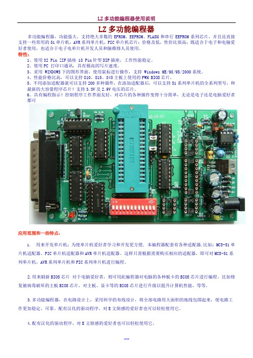
LZ多功能编程器多功能编程器,功能强大。
支持绝大多数的EPROM、EEPROM、FLASH和串行EEPROM系列芯片,并且还直接支持一些常用的51单片机,AVR系列单片机,PIC单片机芯片;价格及低,性价比很高;既适合于电子和电脑爱好者使用,也适合于电子电单片机开发人员和脑维修人员使用。
特性:1、使用32 Pin ZIF插座 18 Pin针型DIP插座,工作性能稳定。
2、使用PC 打印口通讯,具有极高的写片速度。
3、采用 WINDOWS下的图形界面,使用鼠标进行操作,支持 Windows ME/98/95/2000系统。
4、性能价格比高,可以支持810、815、845主板上使用的FWH BIOS芯片。
5、不用添加适配器就可以支持200多种器件,在添加适配器后,可以支持51系列单片机的全系列型号,和最新的大容量程序芯片!支持3.3V及2.9V电压的芯片。
6、具有编程指示!控制程序工作界面友好,对芯片的各种操作变得十分简单,无论是电子还是电脑爱好者都可应用范围和一些特点:1.用来开发单片机:为使单片机爱好者学习和开发更方便, 本编程器配套有各种适配器,比如:MCS-51单片机适配器、PIC单片机适配器和AVR单片机适配器。
这样只需根据需要购买相应的适配器,即可对MCS-51系列单片机,AVR系列单片机和PIC系列单片机进行编程。
2.用来刷新BIOS芯片对于电脑爱好者,则可用此编程器对电脑的各种板卡的BIOS芯片进行编程。
比如修复被病毒破坏的主板BIOS芯片,对主板、显卡等的BIOS芯片进行升级以提升计算机性能,等等。
3.多功能编程器,在电路设计上,采用科学的布线设计,将全部电路用大面积的地线包围起来,使电路工作更加稳定、可靠。
配有汉化的驱动程序,对E文烦感的爱好者也可以轻松使用它。
4.配有汉化的驱动程序,对E文烦感的爱好者也可以轻松使用它。
多功能BIOS 编程器支持的芯片 芯片类型 芯片型号单片机芯片 需51适配器转换座 89系列:Atmel :AT89C51、52、55、 AT89LV51、52、55AT89S8252 (8K+2K)、 AT89S53、 AT89LS8252、AT89LS53AT89C1051、AT89C2051、AT89C4051 (20pin)AT89C51RC (32KB)、 AT89C55WD (6.2V)SST89C54/58、 SI89C52Intel :i87C51、 i87C51FA 、 i87C51FBi8xC51、i8xC52、i8xC54、i8xC5890系列:AT90S1200、AT90S231390S2333、 90S4433、 90S4414、 90S8515、 90S4434、 90S8535,AT90S231316位EPROM(DIP40)(1-4Mbit)27C1024 (27C210)、 27C2048 (27C2002)、 27C4096 (27C4002) 需使用Eprom DIP40转换座 16位EPROM(DIP42)(4-32Mbit)M27C400(DIP40)、 27C800、 27C160、 27C322 需使用Eprom DIP42转换座 电擦除EPROM W27E512、 W27E010、 W27C010、 W27C020、 W27C040SST27SF256、 SST27SF512、 SST27SF010、 SST27SF020MX26C4000Vcc = 3.3-3.6V SST37VF512、 SST37VF010、 SST37VF020、 SST37VF040EEPROM 28C65、28C64、 28C128、 28C256、28C512、 28C010、 28C020、 28C040M28C16A/17A (DIP28)28C16、XLS2816 (DIP24)AT28C64B 、AT28C256、AT28C512、AT28C010、AT28C020、AT28C040FLASH Memory28F64、 28F128、 28F256、 28F512、28F010、 28F020MX26C1000、 MX26C2000、 MX28F1000、 MX28F2000Am28F256A 、 Am28F512A 、 Am28F010A 、 Am28F020Aintel :i28F001BX 、 28F004、 28F008、 28F016SST28SF040A 、LE28F400129F64、 29F128、 29F256、 29F512、29F010、 29F020、 29F040、 29F08029F001、29F002、 29F004、 29F008、 29F016、 29F032AT29C256、 AT29C512、AT29C010A 、 AT29C020、 AT29C040、AT29C040AW29EE512、W29EE011、 W29EE012、 W29C020(128)、W29C040PH29EE010(W29EE011)ASD AE29F1008 (AT29C010)、 AE29F2008 (AT29C020)AT49F512、 AT49F010、 AT49F020、 AT49F040SST39SF010、 SST3S9F020 、SST39SF040AT49F001、AT49F002 、 AT49F008AAm29F512、 Am29F010、 Am29F020、 Am29F040、HY29F08029F002、 29F002T 、 Pm29F002T 使用TSOP48转换座支持: Am29F400、Am29F800、29F160、29F320 (read 、write byte mode) HY29F200、 HY29F400、 HY29F800 、 AT49F2048A 、 AT49F4096A 、 AT49F8192A使用TSOP48转换座支持(Vpp12V ): i28F200、i28F400、i28F800、i28F160 (TSOP48)28F001(DIP32 or PLCC32)使用TSOP48LV转换座支持:29LV200、 29LV400、29LV800、29LV160、29LV320 (read、write byte mode)使用Firmware Hub/LPC (PLCC32)转换座支持:Firmware Hub芯片:82802AB、 82802AC、 AT49LW040、 AT49LW080SST49LF002A、 SST49LF003A、 SST49LF004A、 SST49LF008A LPC flash芯片:SST49LF020、 SST49LF040串行(I2C) EEPROM 24C02、24C04、24C08、24C16、 85C72、 85C82、 85C9224C32、24C64、24C128、24C256、24C512 (全部C、LC系列) PCF8572 或8572,PCF8582或8582,PCF8592或8592Microwire EEPROM 8位模式:93C06、 93C46、 93LC46、 93C56、 93C57、93C66、 93C76、 93C86、93C13、93C1416位模式:AT59C11、 AT59C22、 AT59C13CAT35C102、 CAT35C104、 CAT35C10893C06A 、93C46X、93C56、93C66、93C76、93C86 (NS)PIC单片机16C5X、17XXX、18XXX系列使用PIC单片机转换座支持:12C508、12C508A、12C509、12C509A 12CE518、12CE519 12C671、12C672、12CE673、12CE674 16C505 16C61、16C620、16C621、16C622A 16F627、16F628、16C71、16C715 16C84、16F83、16F84、16F84A 16C64A、16C65A、16C65B、16C67 16C74A、16C74B、16C77 16F871、16F874、16F877 16C62A、16C62B、16C63、16C63A、16C66 16C72、16C72A、16C73A、16C73B、16C76 16F870、16F872、16F873、16F876SPI EEPROM Atmel:AT25010、020、 040 (A8-A0)AT25080、 160、 320、 640、 128、 256 (A15-A0)ST:W95010....256、 Microchip 25x010 - 25x64025010、25020、2504025C080、25C160、25C320、25C640、25C128、25C256、25C512 AT25HP256、AT25HP512AT25HP1024CAT64LCxxx (16位数据I/O)CAT64LC010、 CAT64LC020、 CAT64LC040测试SRAM、非易失SRAM功能DS1220、DS1225Y、 DS1230Y/AB、 DS1245Y/AB、 DS1249Y/AB 6116、 6264、 62256、 62512、 628128EPROM 27C16、27C32、27C64、27C128、27C256、27C512、27C010、27C020、27C040、27C1001 M27C1001、M27C2001、M27C400127C080,M27C801,M87C2572716(Vpp25V)、2732、2764、27128、27256、27512、27010需使用Atmel AT89 PLCC44转换座P8048AH、 P8049AH、P8050AH、 P8042AH (Vea = 12V)P8041、 P8042OTP (read/verify/Progam)P8748、P8749H、P8742H(Vea = 18V)EPROM (read/verify/Progam)D8748、D8749、D8742、D8741、 D8742(Vea = 18V)从上面的列表中,我们可以发现,如果我们使用FWH(PLCC32)转换座,我们用此编程器可以支持最新几乎所有主板上的BIOS芯片,多功能BIOS编程器都可以支持,真正是一款性价比较高的编程器。
佳能iX6500IX6580维修手册
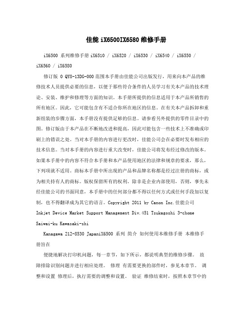
佳能iX6500IX6580维修手册iX6500 系列维修手册iX6510 / iX6520 / iX6530 / iX6540 / iX6550 /iX6560 / iX6580修订版 0 QY8-13DG-000范围本手册由佳能公司出版发行,用来向本产品的维修技术人员提供必要的信息,以便于那些符合条件的人员学习有关本产品的技术理论、安装、维护和修理等方面的知识。
本手册所提供的信息适用于本产品所销售的所有地区。
因此,它可能包含有不适合你所在地区的信息。
在有关本产品拆卸和重新组装的步骤方面,本手册没有提供足够的信息。
请参看另外提供的零件目录中的图。
修订版由于本产品在不断地改进和提高,因此可能包含一些技术上不准确或印刷上的错误之处。
当对本手册的内容进行更改时,佳能公司会在必要时发布相应的技术信息。
当对本手册的内容进行重大改变时,佳能公司将发布经过修改的版本。
如果本手册中的内容不符合本手册和本产品使用地区的法律和规章的要求,那么,下列项就不适用。
商标本手册中所出现的产品和品牌名称都是经过注册的商标,或为相关持有人的商标。
版权保留所有的权利。
除非是企业内部使用,否则,事先未经佳能公司的书面同意,本手册中的任何部分都不得以任何方式或任何手段加以复制,也不得翻译成为其它的语言。
Copyright 2011 by Canon Inc.佳能公司Inkjet Device Market Support Management Div.451 Tsukagoshi 3-chome Saiwai-ku Kawasaki-shiKanagawa 212-8530 JapaniX6500 系列简介如何使用本维修手册本维修手册旨在便捷地解决打印机问题,每一章节,如下所示,都说明典型的维修步骤。
故障排除识别问题并进行相应处理。
修理有需要更换的部件时,参见本章节。
调整和设置修理后,执行需要的调整和设置。
验证维修结束时,按照本章节中的检测流程验证打印机。
OX6580A-D3中文资料
OCXO SERIES 8000 Rev. B"FEATURESSmall OCXO in 1” SQ. packageFrequencies up to 38.880 MHzAT and SC-Cut option"ELECTRICAL PERFORMANCEPARAMETER OCXO SERIES 8000AT CUT CRYSTAL SC CUT CRYSTAL Supply voltage, nom. 5V ±5% Standard (3.3V, 12V Optional)Power dissipation steady state 1.5 Watt Max.Heat up power 3 Watt MaxHeat up time. 3 min MaxFrequency range 1 To 38.880 MHz StandardFrequency Adjustment ±10PPM Min (0 to 5V) ±0.7PPM Min (0 to 5V)±0.05 PPM ±0.1 PPM±0.25 PPM ±0.01 PPM ±0.02 PPM ±0.03 PPMFreq. stability vs. temperatureLX: 0°C to 60°CFZ: -30°C to 70°CD3: -40°C to 85°(Standard, contact factory for different temp ranges and stabilities) Freq. stability vs. supplychanges±0.015 PPM Max for ±5% Change ±0.010 PPM Max for ±5% Change Freq. stability vs. load changes ±0.01 PPM Max for ±5% Change ±0.005 PPM Max for ±5% ChangeLong term stability (Aging) ±4 PPM Max for 10 Years±0.005 PPM/Day Max. ±1 PPM Max for 10 Years ±0.002 PPM/Day Max.Output HCMOS/TTL/Sine 0 to +7dBm (Low voltage CMOS Available)Harmonics, Sub Harmonics -30dBc(Sine Output)Spurious -75dBc(SineOutput) Duty cycle 40/60% to 60/40%(HCMOS)Rise / fall time 10nS Max. (HCMOS,10%~90%Vout, 90%~10%Vout)Short term Stability (10MHz) 1 E-10 /Sec 5 E-11 /SecPhase Noise typical under static condition(Sine Output 10MHZ) Offset Phase Noise10Hz -90 dBc/Hz100Hz -125 dBc/Hz1000Hz -135 dBc/Hz10000Hz -150 dBc/HzOffset Phase Noise10Hz -110 dBc/Hz100Hz -130 dBc/Hz1000Hz -140 dBc/Hz10000Hz -150 dBc/HzNote: All Typical parameters for a 10MHz output and 5V Supply, for different frequencies consult factory" HOW TO ORDER (PART NUMBER)Prefix Output Type Cut TypeSeries Revision Temperature Range Stability Frequency Supply Voltage OX2:HCMOS 4:LVCMOS 6:SINE0:AT (No Vcontrol ) 1: SC (No Vcontrol )4: AT (Elect Vcontrol) 5: SC (Elect Vcontrol)80:8000AFirst letter Lowest Temperature,Second letter Highest Temperature:From A=-55°C to Z=+70°C, Then: 1=+75°C, 2=+80°C, 3=+85°C… in 5°C steps Example: LZ: +0°C to +70°C LX: +0°C to +60°C FZ: -20°C to +70°C FZ: -30°C to +70°C D3: -40°C to +85°CValue x 10E-2 in PPMExample 28=0.28PPM 10= 0.1PPMIn MHZ12:12V 5; 5V 3.3; 3.3VHEIGHT, MAX. “H”: 0.52” / 13.2mmOUTLINE TOLERANCE: ±0.015” / 0.4mmPIN FUNCTIONS: [1] RF OUTPUT [2] GROUND[3] N/C OR CONTROL VOLTAGE[4] NOT CONNECTED [5] SUPPLY VOLTAGE。
第1章微型基础1课件

补码的减法运算: 在补码运算中,可以把有符号数的减法 运算转换为加法运算。
例 :求61-59的值 解: (61)+(-59)=(61)补+(-59)补 =0011 1101+ 1100 0101 =1 00000010=2
自动丢失
溢出:
01111110
+ 00000101 10000011
+126
2.进位计数制的表示方法
任意一个K进制数S表示为:
(S )k Sn1 K n 1 S n 2 K n 2 S0 K 0 S 1 K
i
n 1
Si K i
其中: Si -- S的第i位数码,可以是K个符号中任何一个; n,m – 整数和小数的位数; K -- 基数; Ki -- K进制数的权;
微机原理及应用
第一章 微机基础
§1.1 微机概述 1.1.1 微机发展概况
1.计算机的发展
依据计算机的主要电子元器件,计算机的发展
经历了四代: 第一代:电子管计算机时代 第二代:晶体管计算机时代 第三代:集成电路计算机时代 第四代:大规模集成电路计算机时代 趋势:非“冯.诺依曼”计算机时代(第五代)
1.3 微机的一般概念
1.3.1 计算机的基本组成和工作原理
1.计算机的基本组成
运算器
输入设备
存储器
输出设备
结果
控制器
2.计算机的工作原理 存储程序:把已编制好的程序和数据先送 入存储器中保存起来。 程序控制:
1.3.2 名词术语
1.微处理器
微处理器(Microprocessor),是由一 片或几片大规模集成电路组成的具有运 算器和控制器的中央处理机部件,即 CPU(Certal Processing Unit)。
W78E58中文
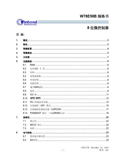
W78E58B规格书8位微控制器目录:1.概述 (3)2.特性 (3)3.管脚配置 (4)4.管脚描述 (5)5.方块图 (7)6.功能描述 (8)6.1 RAM (8)6.2 定时器0,1,2 (8)6.3 时钟 (9)6.4 晶体振荡器 (9)6.5 外部时钟 (9)6.6 电源管理 (9)6.7 减少EMI辐射 (9)6.8 复位 (9)6.9 I/O口4 (11)6.10 INT2/INT3 (12)6.11 P4口基地址寄存器 (14)6.12 在线编程(ISP)模式 (15)6.13 在线编程控制寄存器(CHPCON) (17)6.14 F04KBOOT 模式(从LDROM启动) (18)7.保密位 (22)7.1 锁止位 (22)禁止 (22)7.2 MOVC7.3 加密 (22)8.电气特性 (23)8.1 绝对最大额定值 (23)8.2 DC特性 (23)出版日期: December 22, 20048.3 AC特性 (25)8.3.1时钟输入波形 (25)8.3.2程序读取周期 (26)8.3.3数据读取周期 (26)8.3.4数据写周期 (27)8.3.5端口访问周期 (27)9.时序波形图 (28)9.1 程序读取周期 (28)9.2 数据读周期 (28)9.3 数据写周期 (29)9.4 端口访问周期 (29)10.典型应用电路 (30)10.1 扩展的外部程序存储器和石英晶体 (30)10.2 扩展的外部程序存储器和振荡器 (31)11.封装尺寸 (32)11.1 DIP40 (32)11.2 44 管脚PLCC (33)11.3 44 管脚PQFP (34)12.应用指南 (35)12.1 ISP 软件编程示例: (35)13.文件版本描述 (42)1. 概述W78E58B是具有带ISP功能的Flash EPROM的低功耗8位微控制器;ISP功能的Flash EPROM可用于固件升级。
硬盘盒主控芯片介绍

硬盘盒主控芯片介绍元谷选元谷刀锋不如选元谷星钻iPD-USB 2.5寸串口SATA 移动硬盘盒元谷PD2500也可以元谷的做工没得挑,最关键得是看一下内部芯片。
一些主流硬盘盒芯片介绍IDE芯片:68300A/B/C赛普拉斯公司最出名的芯片,由原ISD公司的经典产品ISD300A 控制芯片二次开发得来,用于2.5及3.5系列IDE设备,优点是兼容性好,故障率低,缺点是偶尔会供电不足现象,元谷公司早期采用68300B的PD2500盒子就出现过此类问题,68300C得到较好改善。
经典的有:元谷PD2500、奈雷特D2/D4、瀚士威H570C、H560C等。
后期好一点的盒子USB线上都带双接头取电。
友情提示:赛普拉斯公司目前还没推出支持SATA硬盘的芯片,所以请不要开口赛普拉斯、闭口赛普拉斯。
INITIO 1511美国英尼硕公司主推的IDE控制芯片,各项技术指标都可以赛普拉斯芯片,但主要是价位较高,况且受产能限制,在市面上见的不多。
元谷刀锋2500IDE采用此款芯片。
NT68320 BE/GP图美自有芯片,图美是目前国内唯一能研发控制芯片的硬盘盒厂商,技术实力可见一斑,BE为备份型,GP为高速型。
整体评价介于PL-2506和68300之间。
NEC D720133GB这个不用多说,NEC的牛X芯片,性能速度兼容性绝对一流,但是价格也是一流。
我目前的产品线只有微星原装V3使用的是这款芯片,不过后期我估计也要换掉,因为只能支持IDE硬盘,不利于工厂控制成本,现在IDE笔记本盘比SATA盘要贵的多。
PL-2506旺玖公司的主要产品,价位中下,兼容性不错,功耗控制也较好,图美U225X就是采用这款芯片。
M110 台湾奇岩公司的得力产品,众多知名厂商选用,通用性强,1.8寸-5.25寸IDE设备通吃,性能不错。
缺陷还未发现。
蓝硕的USB易驱就是用的M110。
GL811/811E科X等杂牌用的最多的芯片,价格低廉,参数一般。
编译型一体机硬件手册说明书

编译型一体机硬件手册二、HMI 接口及PLC 端子说明1. GC-043系列显控控制器(GC-043-16M4AI-C 为例)PLC 端子序号 接口功能① 数字量输入。
其中24V 、0V 为内部输出电压接口。
② 数字量输出。
其中PD 为输出保护,接输出电源正极。
③模拟量输入。
其中NTC 、GND 为冷端热敏电阻接口。
HMI 接口序号 接口功能 ① 电源输入接口 ② 485通讯口 ③ U 盘口 ④USB 通讯口①② ③ ④2. GC-050系列显控控制器(GC-050-32MAI-C) PLC端子HMI接口3. GC-070系列显控控制器(GC-070-32MAA-C为例) PLC端子HMI接口三、AIAO规格及接线说明1. GC-043、GC-050系列机型模拟量输入规格及配线图AI0~AI3的可选模式有4种:⚫电压模拟量输入范围:0~5V;⚫电流模拟量输入范围:4~20mA;⚫K型热电偶输入,测温范围:-50℃~ 900℃;⚫T型热电偶输入,测温范围:-250℃~ 400℃;注意事项:1. 电压电流模式下,AI寄存器数据类型为16位无符号整数;2. 温度模式下,AI寄存器数据类型为16位有符号整数,显示值为实际温度的10倍(如显示254,即表示当前测量温度为25.4℃)。
若热电偶或热敏电阻出现断线、测温数值超量程等异常情况,对应通道的AI寄存器显示32767;3. 热电偶模式下,必须在NTC、GND处接入热敏电阻,用以测量冷端温度。
AI30寄存器显示AI0和AI1通道共用的冷端温度测量值,AI31寄存器显示AI2和AI3通道共用的冷端温度测量值。
若冷端热敏电阻测温数值异常,AI30/AI31寄存器显示-32767;4. 安装温度传感器时,热电偶的测温部分要避免接触非测温目标的物体。
同时要尽量减小非屏蔽导线的长度,避免导线外露,以减少外部干扰,降低对测温精度的影响。
●模拟量电压输入Samkoon 控制器B- RB B+A- RA A+250Ω- +250Ω-+●模拟量电流输入Samkoon控制器B-RBB+A-RAA+250Ω250ΩB- RB B+A- RA A+250Ω250ΩSamkoon 控制器●K/T 型热电偶模拟量输入+ +2. GC-070系列机型模拟量输入输出规格及配线图(1)电压/电流模拟量输入GC-070-24MAA-C、GC-070-32MAA-C有4路电压/电流模拟量输入通道AI0~AI3,可选模式有3种:⚫电压模拟量输入范围:0~5V⚫电压模拟量输入范围:0~10V⚫电流模拟量输入范围:4~20mA注意事项:电压电流模式下,AI寄存器数据类型为16位无符号整数。
电脑硬件信息
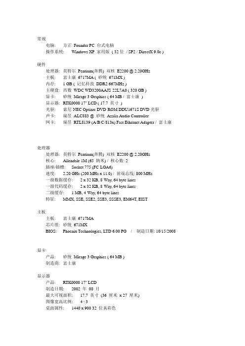
常规电脑: 方正Founder PC 台式电脑操作系统: Windows XP 家用版( 32位/ SP2 / DirectX 9.0c )硬件处理器: 英特尔Pentium(奔腾) 双核E2200 @ 2.20GHz主板: 富士康6717MA ( 矽统671MX )内存: 1 GB ( 记忆科技DDR2 667MHz )主硬盘: 西数WDC WD3200AAJS-22L7A0 ( 320 GB )显卡: 矽统Mirage 3 Graphics ( 64 MB / 富士康)显示器: RTK0000 17'' LCD ( 17.7 英寸)光驱: 索尼-NEC Optiarc DVD-ROM DDU1671S DVD光驱声卡: 瑞昱ALC883 @ 矽统Azalia Audio Controller网卡: 瑞昱RTL8139 (A/B/C/813x) Fast Ethernet Adapter / 富士康处理器处理器: 英特尔Pentium(奔腾) 双核E2200 @ 2.20GHz核心: Allendale 1M (65 纳米) / 核心数: 2插座/插槽: Socket 775 (FC-LGA6)速度: 2.20 GHz (200 MHz x 11.0) / 前端总线: 800 MHz一级数据缓存: 2 x 32 KB, 8-Way, 64 byte lines一级代码缓存: 2 x 32 KB, 8-Way, 64 byte lines二级缓存: 1 MB, 4-Way, 64 byte lines特征: MMX, SSE, SSE2, SSE3, SSSE3, EM64T, EIST主板主板: 富士康6717MA芯片组: 矽统671MXBIOS: Phoenix Technologies, LTD 6.00 PG / 制造日期: 10/15/2008显卡产品: 矽统Mirage 3 Graphics ( 64 MB )制造商: 富士康显示器产品: RTK0000 17'' LCD制造日期: 2002 年08 月最大可视面积: 17.7 英寸(36 厘米x 27 厘米)图像宽高比例: 4 : 3桌面属性: 1440 x 900 32 位真彩色内存DIMM 0: 记忆科技DDR2 667MHz 1GB硬盘产品: 西数WDC WD3200AAJS-22L7A0 ( 320 GB / 7200 转/分蓝盘) 缓存: 8 MB硬盘已使用: 共757 次,累计2205 小时接口: SATA Rev 2.5数据传输率: 300 MB/秒特征: S.M.A.R.T, 48-bit LBA, NCQ光驱产品: 索尼-NEC Optiarc DVD-ROM DDU1671S DVD光驱缓存/固件: 198 KB / 1.11--------鲁大师: V2.66--------网络网卡: 瑞昱RTL8139 (A/B/C/813x) Fast Ethernet Adapter / 富士康输入设备键盘: 标准101/102 键或Microsoft 自然PS/2 键盘鼠标: HID-compliant 鼠标音频声卡: 瑞昱ALC883 @ 矽统Azalia Audio Controller--------鲁大师: V2.66--------。
方正科技 笔记本电脑 方正A580 产品说明书
笔记本电脑幞于高科技纾密产品,请您务必仔细阅读下面使用提示。
1.LCD显示幏保养: · 不要在笔记本上放任何重物。 · 使用手提箱或背包时,请确保您溡有在包内装太多东西,并且溡有在笔记本 包和LCD背部增加额外的压力。 · 不要抓、扭或撞击LCD幏幕表面。 · 不要帆LCD幏幕置于很热或很潮湿的环境中。 · 不要让LCD幏幕暴露在直帄的阳光或很强的荧光下太长时间。 · 不要在LCD幏与键盘之间放置任何东西,例如:铅笔、文件等,这会损坏或 刮伤LCD幏。请勿使用有腐蚀性的清洁剂擦拭LCD幏,这会损伤幏幕。 · 为保护LCD幏幕,请在不使用或外出携带时在幏上加保护幂,以免幏幕磨损。
方正科技保留对说明书解释和修改的权利,对说明书的任何修正、更新、解释帆在 方正科技网站()予以公布,请您留意。
致踢!
方正科技集团股份有 限公司
目录
1 滨意事项
1
1.1 特别提示
1
1.2笔记本使用重要提示—请务必阅读
1
1.3 滨意事项
2
1.4笔记本电脑电湠使用须知—请务必阅读
之地的电源供应需稳定且不受干扰。若您不清楚当地电器规格,请与您的经销商或所处 当地的电力公司洽询。基于安全考虑,电源插头的接地线,请勿随意破坏。拔电源时, 避免直接用拉扯的方式帆电线拔出,务必从插头处拔起,以确保安全。清洁电脑前,切 记务必先拔掉电源插头。请勿拆开电源适配器。
6.请勿使用非本机所配专用电源适配器,否则有可能造成电脑损坏。 7.请勿单手取放笔记本电脑或使您的笔记本电脑处于不平衡状态。 8.本产品只能由方正科技授权服务人员进行拆装,请您保证币条完整,否则可能 会影响您享受保修或“三包”服务。 9.如果您设置了密码,请千万不要忘记,否则可能导致不能开机。如果忘记了密 码,请与供货商或授权维修站联绻,但这可能会损坏您的所有资料。 10.当手动弹出光驱时,请勿使用铅笔等易折断的物品,以免堵住紧急弹出孔。
- 1、下载文档前请自行甄别文档内容的完整性,平台不提供额外的编辑、内容补充、找答案等附加服务。
- 2、"仅部分预览"的文档,不可在线预览部分如存在完整性等问题,可反馈申请退款(可完整预览的文档不适用该条件!)。
- 3、如文档侵犯您的权益,请联系客服反馈,我们会尽快为您处理(人工客服工作时间:9:00-18:30)。
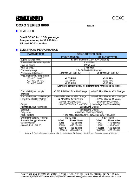
OCXO SERIES 8000 Rev. B
"FEATURES
Small OCXO in 1” SQ. package
Frequencies up to 38.880 MHz
AT and SC-Cut option
"ELECTRICAL PERFORMANCE
PARAMETER OCXO SERIES 8000
AT CUT CRYSTAL SC CUT CRYSTAL Supply voltage, nom. 5V ±5% Standard (3.3V, 12V Optional)
Power dissipation steady state 1.5 Watt Max.
Heat up power 3 Watt Max
Heat up time. 3 min Max
Frequency range 1 To 38.880 MHz Standard
Frequency Adjustment ±10PPM Min (0 to 5V) ±0.7PPM Min (0 to 5V)
±0.05 PPM ±0.1 PPM
±0.25 PPM ±0.01 PPM ±0.02 PPM ±0.03 PPM
Freq. stability vs. temperature
LX: 0°C to 60°C
FZ: -30°C to 70°C
D3: -40°C to 85°
(Standard, contact factory for different temp ranges and stabilities) Freq. stability vs. supply
changes
±0.015 PPM Max for ±5% Change ±0.010 PPM Max for ±5% Change Freq. stability vs. load changes ±0.01 PPM Max for ±5% Change ±0.005 PPM Max for ±5% Change
Long term stability (Aging) ±4 PPM Max for 10 Years
±0.005 PPM/Day Max. ±1 PPM Max for 10 Years ±0.002 PPM/Day Max.
Output HCMOS/TTL/Sine 0 to +7dBm (Low voltage CMOS Available)
Harmonics, Sub Harmonics -30dBc(Sine Output)
Spurious -75dBc(Sine
Output) Duty cycle 40/60% to 60/40%(HCMOS)
Rise / fall time 10nS Max. (HCMOS,10%~90%Vout, 90%~10%Vout)
Short term Stability (10MHz) 1 E-10 /Sec 5 E-11 /Sec
Phase Noise typical under static condition
(Sine Output 10MHZ) Offset Phase Noise
10Hz -90 dBc/Hz
100Hz -125 dBc/Hz
1000Hz -135 dBc/Hz
10000Hz -150 dBc/Hz
Offset Phase Noise
10Hz -110 dBc/Hz
100Hz -130 dBc/Hz
1000Hz -140 dBc/Hz
10000Hz -150 dBc/Hz
Note: All Typical parameters for a 10MHz output and 5V Supply, for different frequencies consult factory
" HOW TO ORDER (PART NUMBER)
Prefix Output Type Cut Type
Series Revision Temperature Range Stability Frequency Supply Voltage OX
2:HCMOS 4:LVCMOS 6:SINE
0:AT (No Vcontrol ) 1: SC (No Vcontrol )
4: AT (Elect Vcontrol) 5: SC (Elect Vcontrol)
80:8000
A
First letter Lowest Temperature,
Second letter Highest Temperature:
From A=-55°C to Z=+70°C, Then: 1=+75°C, 2=+80°C, 3=+85°C… in 5°C steps Example: LZ: +0°C to +70°C LX: +0°C to +60°C FZ: -20°C to +70°C FZ: -30°C to +70°C D3: -40°C to +85°C
Value x 10E-2 in PPM
Example 28=
0.28PPM 10= 0.1PPM
In MHZ
12:12V 5; 5V 3.3; 3.3V
HEIGHT, MAX. “H”: 0.52” / 13.2mm
OUTLINE TOLERANCE: ±0.015” / 0.4mm
PIN FUNCTIONS: [1] RF OUTPUT [2] GROUND
[3] N/C OR CONTROL VOLTAGE
[4] NOT CONNECTED [5] SUPPLY VOLTAGE。