SPS-43-48H-HP-TDE中文资料
SPS-43-48H-HP-CDE中文资料
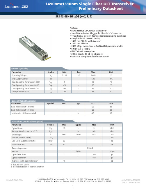
Transmitter Specifications (Electrical) Parameter Input Differential Impedence Single Ended data input swing (ac coupled inside module) Tx Disable (LVTTL) Tx Enable (LVTTL) Tx_Fail_High Tx_Fail_Normal Receiver Specifications (Optical) Parameter Wavelength Data Rate (burst-mode) Receiver Sensitivityc Receiver Overloadc Receiver Burst-mode Dynamic Ranged BRST_Det Assert (Signal Detected) Receiver CID Tolerance Damage Threshold for Receiver Maximum Reflectance of Receiver P_DET CID Pin, damage RX_r RENS ROL Symbol λ Min 1260 -8 15 72 3 Typical 1310 1244 20 Max 1360 -28 -28 -20 Unit nm Mbps dBm dBm dB dBm bits dBm dB Symbol Rin Vin, p-p Vd Ven V_Fail V_Normal Min 80 300 2 0 2.4 0 Typical 100 Max 120 1200 Vcc 0.8 Vcc 0.4 Unit Ω mV V V V V
元器件交易网1490nm/1310nm Single Fiber OLT Transceiver
德铂思产品介绍课件

SPS放电等离子烧结炉

空阀门采用气动蝶阀(上海真空阀门),真空测量采用成都睿宝的真空计。真空系统上设有电
动放气阀及主充气阀,充气阀为日本 CKD 品牌产品,充气阀通过软管与流量计相联接,可
实现自动充放气。
5.控制系统:控制系统由我公司自行开发人机对话操作软件,画面友好,操作简单,可对
炉内工况进行实时监测,软件彩色模拟屏显示,加热升温、压力显示及真空阀门的控制都集
统等组成。设备包括全数字化液压控制系统,带有精确的速度/压力控制,配置光学位置传
感器。双层全不锈钢设计、水冷炉室,静态和流动的工艺气体控制系统。电源发生器产生可
编程的直流电脉冲,满足各种个性化需求。烧结温度可以达到 2400℃。所有的工艺参数都
可以编程,烧结过程可以自动运行。工艺控制系统可以灵活地处理烧结工艺菜单,也可以通
新材料伙伴 真空炉专定
上海晨鑫电炉有限公司
咨询电话:13817293862
____________________________________________________________________________________________
4.真空系统:采用壹台直联泵(成都南光)及壹台油扩散泵(成都南光),配有电磁放气阀,真
红外温孔上安装红外测温仪,为防止观察窗玻璃因挥发而污染影响测温,故用了气帘及测温
靶结构,使用户大大减少了清洁玻璃的次数,热电偶设有两支,其中一支在低温工作,可与
红外仪自动转换,另一支为超温保护用,即当炉温异常高超过正常值时自动切断加热保护系
统安全。
<4>:炉门上设有压力表及观察窗,手动开启,手动压紧。
注:我公司是国内第一家生产 SPS 放电等离子热压烧结炉的厂家,关键技术
我们已经申请了专利(脉冲电源和模具),产品质量达到或优于国外同类产品。
CMG-40TDE说明书

CMG-40TDE一体化地震仪培训资料目录1. CMG-40TDE总体介绍 (3)1.1 开箱检查 (5)1.2 接口介绍 (5)1.3 CMG-40TDE初始化 (6)1.3.1 通过网页初始化IP地址设置 (6)1.3.2 通过超级终端初始化IP地址设置 (9)1.3.3 SCREAM软件设置 (11)1.3.3 GPS信号检查 (14)1.3.4 数据存储介质 (15)2. CMG-40TDE安装 (18)2.1山洞安装环境 (18)2.1.1 地点选择 (18)2.1.2 温度稳定性 (19)2.2坑体式安装环境 (20)2.3其他安装环境 (21)2.4具体安装步骤 (23)3. CMG-40TDE传感器部分 (30)3.1 地震计标定 (30)4. CMG-40TDE数据采集器部分 (35)4.1 数据采集器使用 (35)4.1.1 配置窗口 (35)4.1.2 控制窗口 (37)4.2 数据采集器升级 (38)5. CMG-40TDE通信单元部分 (40)5.1 IE浏览器控制和配置数据采集器 (41)5.2 NTP方式对数据采集器授时 (42)5.3 CMG-EAM在线远程升级 (45)6. SCREAM软件 (47)6.1 SCREAM软件主窗口 (47)6.2 波形显示窗口 (49)6.3 SCREAM文件设置 (50)7.问题及解决 (53)8. 接口定义 (55)1. CMG-40TDE总体介绍CMG-40TDE是便携式一体化地震仪,其密封的不锈钢外壳内包含了一个三分向宽频带负反馈地震计、一个24位数据采集器以及一个功能灵活的数据通信和存储单元。
仪器接上电源就是一个完整的测震系统。
图 1CMG-40TDE坚固防水的不锈钢外壳设计非常方便野外安装。
由于传感器内部采用轻便耐用的部件,地震计不需要锁摆,只需要加电,地震计就可以马上记录地面的运动。
此外,地震计在水平平面3度以内不需要重新调零。
Parker Hose 产品目录说明书
More of what you need to work smarter,AccessoriesV i s u a l I n d e x59RG D-17T1RG D-17Partek Sleeve D-18ParKoil™ (PG) D-19GuardsO-Rings for CA, CE,CF MetricFlange “D” Rings Caterpillar ® Style FlangesT ube O-Ring Fittings and CompressorFittingsO-Rings for Compression Fittings (IT126)O-Rings for C9, OC, 1C Metric Swivels88HC-H Clamp D-2488DB Clamp D-24Hose Assembly D-26Workstations3/4 Reel Rack D-2772B-Cabinet D-28HR6 Hose Bin D-28Hose Adapters D437° Flare Metric Triple-Lok ®Sizes: 6 mm – 38 mmMaterials : Steel, Stainless Steel Pressures : Up to 7200 psi60° Cone BSPPK4Sizes : 1/8” – 2”Materials : Steel Pressures : Up to 5000 psi30° Flare Komatsu StyleSizes : M14 x 1.5 – M33 x 1.5Materials : Steel Pressures : Up to 4000 psiO-Ring Face-Seal Metric Seal-Lok™Sizes: 1/4” – 2”Materials: Steel, Stainless Steel Pressures: Up to 9200 psiJapanese Industrial Standard JISSizes : 1/4” – 1”Materials : Steel Pressures : Up to 5000 psiWhen ordering Parker Adapters, please state the Catalogued Number of each type of adapter desired. Be sure to double check tube and hose sizes of items required.To select proper seal materials for specific applications, refer to Media Compatibility Chart in Tube Fitting Catalog 4300, or contact your Parker Tube Fitting Distributor.If in doubt about which type or size of fitting to specify, consult your Parker Tube Fitting Distributor. In addition Parker Field Sales, Technical Services,the Tube Fitting Division and your local Parker Service Center will help you find answers to all your issues.Phone: (614) 279-7070Fax: (614) 279-7685Web: /tfdNote: Refer to Parker Catalog 4300 for more detailed application information.CALL TOLL-FREE 1-800-C PARKER (1-800-272-7537)Parker Information Center for catalogs, literature or additional information.O-Ring Face-Seal Seal-Lok™ Sizes: 6 mm – 38 mm Materials: Steel, Stainless Steel Pressures: Up to 9200 psi37° Flare FittingsTriple-Lok ®Sizes: 1/8” – 2”Materials: Steel, Stainless Steel, BrassPressures: Up to 9000 psiPipe Fittings and Port AdaptersSizes: 1/8” – 2”Materials : Steel, Stainless Steel, BrassPressures : Up to 7200 psiPipe SwivelsSizes : 1/8” – 2”Materials : Steel, Stainless Steel Pressures : Up to 5000 psiConversion AdaptersSizes: 1/4” – 1-1/2”Materials : Steel, Stainless Steel Pressures : Up to 7700 psiHydraulic Flange and Flange AdaptersSizes : 3/4” – 3”Materials : Steel, Stainless Steel Pressures : Up to 6000 psi15T3SAE (Code 61) Flange – Male SAE (JIC) 37˚ FlareCaution: Do not use the T3 flange to tube or swivel nut to tube adapter in hose assembly applications inwhich pressures exceed the SAE100R2 working pressure range.17T3SAE (Code 61) Flange – Male SAE (JIC) 37˚ Flare - 45˚ Elbow19T3SAE (Code 61) Flange – Male SAE (JIC) 37˚ Flare - 90˚ Elbow39T3Male - Female Swivel - SAE (JIC) 37˚ - 90˚ Elbow41T3Male - Female Swivel - SAE (JIC) 37˚ - 90˚ Elbow - Long4AH3SAE Code 61 Flange - Male SAE (JIC) 37˚ Flare - 5000 psi Caution: Do not use the T3 flange to tube or swivel nut to tube adapter in hose assembly applications in which pressures exceed the SAE100R2 working pressure range.4FH3SAE Code 61 Flange - Male SAE (JIC) 37˚ Flare - 5000 psi -45˚ Elbow4NH3SAE Code 61 Flange - Male SAE (JIC) 37˚ Flare - 5000 psi -90˚ Elbow6AH3SAE Code 62 Flange - Male SAE (JIC) 37˚ Flare6FH3SAE Code 62 Flange - Male SAE (JIC) 37˚ Flare - 45˚ Elbow4AJMCode 61 Flange - Male Seal-Lok4FJMCode 61 Flange - Male Seal-Lok - 45˚ Elbow4NJMCode 61 Flange - Male Seal-Lok - 90˚ Elbow6NH3SAE Code 62 Flange - Male SAE (JIC) 37˚ Flare - 90˚ Elbow6NJMCode 62 Flange - Male Seal-Lok - 90˚ Elbow6FJMCode 62 Flange - Male Seal-Lok - 45˚ Elbow6AJMCode 62 Flange - Male Seal-LokNote:*5000 psi with 4A, 4F and 4N Fittings and 50H Flange Halves.There are two non-interchangeable SAE split flanges: a: S tandard or Code 61 is for 3,000psi to 5,000psi maximum, depending on size.b.H igh Pressure or Code 62 is for 6,000psi maximum, r egardless of size. The flange head is “V” notched for identification.Consult these tables to determine flange halves and flange kits specifications.High Pressure (Code 62)Standard Pressure (Code 61)Note: For use with 4A, 4F and 4N Flanges.50H5000 psi Flange Half (Code 61)Note: For use with 4A, 4F and 4N Flanges.Note: High pressure applications also require the use of Code 61 Flange End hose fittings.51HSAE Flange Half (Code 61)5050HK5000 psi Flange Kit (Code 61)5151HKSAE Flange Kit (Code 61)HFHSAE Flange Half (Code 62) HFHFHKSAE Flange Kit (Code 62) 8FHFlange Half (8000 psi)8FHFHKFlange Kit (8000 psi)DIN and ISO Metric PortsDIN (German) and ISO (International Organization for Standardization) flange heads are the same as SAE flange heads. By comparison, the ports have the same configura-tion except that the DIN and ISO Type I ports accept metric bolts. This requires specialflange halves in most sizes.Note: High pressure applications also require the use of Code 62 Flange End hose fittings.M1HDIN (ISO) Flange HalfM1M1HKDIN (ISO) Flange Kit (Code 61)M2M2HKDIN (ISO) Flange Kit (Code 62)M2HDIN (ISO) Flange Half (Code 62)711509O-Rings - SAE Thread (Compound N552-90)*711510O-Rings - Code 61 and Code 62 Flanges (Compound N552-90)**Note: F or use with petroleum base fluids, other compounds available for Phosphate Ester fluids.Please contact The Parker Hannifin Seal Group/O-Ring Division (1-800-C-PARKER) for additional information.C9RG O-Rings for CA, CE, CF MetricC9RG O-Rings for C9, OC, 1C Metric SwivelsD9DTBonded Seal for BSPP Port Fittings*Note: D 9DT must be ordered from the Tube FittingsDivision. Please contact TFD for additional size and product information.XARGFlange “D” Rings Caterpillar ®Style FlangesJ0RGO-Rings - Seal-Lok ®Note: O -Rings for use in Seal-Lok ® connections are illustrated in actual size. Part numbers for O-Ringsused in Seal-Lok ® and in SAE port connections are also listed in the table. O-Rings are supplied in Nitrile NBR compound, 90 durometer hardness.SAE 711509-4-8Seal-Lok J0RG-8-8Photo shows an actual comparison between an SAE port O-Ring (top) and a Seal-Lok ® O-Ring (bottom). They differ in both diameter and cross section.8ARGFlange “D” Rings for 76 Series Style FlangeT1RGO-Rings for Compression Fittings (1T126)Charge Ports CapsR134aR12CORGCaptive O-Ring Assembly ToolsParker’s new CORG Assembly Tools are designed to facilitate the installation of the O-Ring into the half-dovetail groove of the O-Ring face seal fitting.Note: C ORG Assembly T ools must be ordered from the T ube Fittings Division (614) 279-7070.Note: O -Rings listed are for use with petroleum base fluids. Other compounds are available for Phosphate Ester fluids by special order. For Viton ® or otherO-Ring compounds, consult Parker Hannifin, Seal/O-Rings Products Division (1-800-C-PARKER.)Bench TypeHand Type59RGO-Rings for Tube O-Ring Fittingsand Compressor FittingsNote:T he above O-Rings (RG) have HNBR compound number N1195-70 (green).Accessory Selection Guide – Partek Sleeve (AS-B, AS-Y or PS)Note: T he inside flat “A” dimension correspondswith the inside diameter “B” dimension. For example, AS-Y -13 flat surface “A” is 1.34 in. This offers a .86 in. inside diam-eter “B”. Hose with a smaller O.D. can be specified for this size sleeve. Parker 201-5 hose has a .58 in. O.D. and can easily be inserted in the Partek AS-Y -13Sleeve.Note: 1. T he dimensions shown are related to the hose outside diameter and may not fit over the fitting. For over the fitting applications, a larger sizesleeve may be required.2. Cut lengths are available. Contact your local distributor for prices ().Partek SleevePartek “PS” SleeveParker’s Partek Nylon Protective Sleeving gives you tough hose abrasion protection two ways. First, per the ISO 6945 specification, Partek has a unique tubular weave nylon construction, Partek “AS” is strong enough to withstand greater than 200,000 abrasion cycles without wearing through the fabric at any loca-tion. Partek “PS” can withstand greater than 50,000 abrasion cycles. In addition, this weave also gives an exceptionally smooth interior wall, allowing rubber hose to move freely inside the sleeve. This provides easy installation and prevents any internal abrasion problems. Partek sleeving is available in either black or yellow and in sizes to fit most hydraulic hose. Partek, the quick and easy solution to hose protection in high-abrasion areas.Temperature Range: -67°F to +248°F (-53°C to +120°C)Accessory Selection Guide – PolyGuard (HG)• S hield hose from abrasion and cuts • Minimize kinking• Cannot rust or corrode • R esist water, oil, gasoline, hydraulic fluid, and most solvents • I deal for bundling plastic tubing or hose lines • E asy to install without removing hose lines; no clamps neededPolyGuardHeavy-duty polyethylene provides protection in rugged operating conditions.Great for b undling high-pressure hose lines.Cut edges can be smoothed by applying heat.CAUTION: This material will support combustion.Color: BlackTemperature Range:0˚F to +200˚F (-17˚C to +93˚C)Parkoil ™Lower-cost protection for applications that call for a tighter bend radius and are less demanding.Cut edges can be smoothed by applying heat.CAUTION: This material will support combustion.Color: BlackTemperature Range:0˚F to +200˚F (-17˚C to +93˚C)Accessory Selection Guide – ParKoil ™ (PG)Accessory Selection Guide – Spring Guard and Armor GuardNote:Spring Guard and Armor Guard are packaged in 10 ft. pieces.Parker Spring Guard and Armor Guard are two products that prolong the life of hose lines that are exposed to rugged operating conditions. They distribute bending radii to avoid kinking in hose lines and protect hose from abrasion and deep cuts. Guards areconstructed of steel wire and plated to resist rust.Spring Guard (SG)Armor Guard (AG)Accessory Selection Guide – Firesleeve (FS-F)Parker Firesleeve is a flame resistant sheath that protects the hose from extreme temperature conditions. Firesleeve easily slides over hoses and readily expands over fitting. It can be assembled with Parker FSC or properly sized wormgear clamp.Construction: Braided fiberglass sleeve and an orange,bonded and seamless silicone rubber cover.Specifications: Conforms to SAE Aerospace Standard 1072A Type 2A.Temperature Range:-54˚C to +260˚C (-65˚F to +500˚F).Note: T he Firesleeve inside dimension (I.D.)must exceed the outside diameter (O.D.) of the hose and offer an allowance for easy hose insertion. For example, 201-16 has a 1.23 in. O.D. FS-S-24, with an I.D. of 1.46 in., is the suggested Firesleeve. Note: P arker FSC Clamp fits all hoses up to2 in. O.D. Note: P arker HC Clamps (wormgear) are listedon page D-24.Note: See Page D-22 for Firesleeve assembly instructions.Firesleeve (FS-F)FSC ClampPart Number: FSC(One size fits all hoses up to 2 inch O.D.)Accessory Selection Guide – Firesleeve (cont.)1. A ssemble one end fitting on hose. Cut firesleeve to same length as hose. Cover approximately 1” of each end of fire-sleeve with FSS sealant and allow to dry.2. P ush firesleeve back from cut end of hose and assemble the second end fitting. Then pull firesleeve completely over both sockets.3. I nsert tail of FSC clamp into FST clamping tool.4. P osition clamp around middle of socket and tighten with tool. Bend end of band back over buckle. Repeat on other end.Repair any scuffs or abrasions in firesleeve with FSS sealant.FSC ClampUsed to attach firesleeve around socket on hose sizes with a 2” maximum O.D.FST Clamp ToolPart Number: FST -711617 Used to secure FSC clamp.FSS Firesleeve SealantKeeps end of firesleeve from fraying - for neater, longer lasting installation.FiresleeveAssembly InstructionsAccessory Selection Guide – CL ClampVinyl coated steel clamps provide hose support where long lengths are used. Provides neater installation of hose lines, minimizes hose chafing and prevents damage to hose.Material: CR Steel with Zinc PlatingCoating: Black Vinyl Plastisol - 0,8 mm (0.03 inch) thick.Temperature Range:-40°C to +107°C (-40°F to +225°F).Accessory Selection Guide – HC, 88HC-H and 88DB ClampThe Parker HC Clamp is a stainless steel worm gear clamp designed for low presure industrial hose applications.Material: Stainless steelSpecifications: SAE J1508, Type F and Type HD88HC-HSeries Hose Clamp(High Torque Wormgear)88DBSeries Heavy Duty Hose Clamp(Double Bolt Hose Clamp)HC Hose Clamp TableNote: See 88 Series Assembly Instructions for proper 88HC-H clamp attachment.Accessory Selection Guide – Protection Shields (HP , HT, and HP-B)Prevent hose abrasion while extending your hose life. Parker Hose Protection Shields extend hose life by protecting the hose from abrasion that occurs when hose rubs against other hose, metal or concrete. Parker hose shields are resistant to oil, lubricants, gasoline, most solvents and can withstand ambient temperatures from -40° to +300° F . Easily installed and secured by cable ties without disconnect-ing any hose lines. Use with hose from 1/4” to 2” I.D.♦ Eliminate hose abrasion on concrete, metal or any rough surface. ♦ Guard against hose deterioration on mobile hydraulic equipment. ♦Let Parker fill all your hydraulic and pneumatic hose product needs.Hose Protector Shields are a fast and extremely cost effective way to isolate fluid lines from direct contact with other lines, components or structural members. They’re available in 4-inch, 6-inch and 8-inch lengths and the width can be trimmed to satisfy a variety of situations. These flexible protectors simply clamp around the hose and are securely held in place by nylon cable ties which are included. The cable ties are recessed in molded grooves to protect them from abrasion. You don’t need to disconnect a line to install a Parker Hose Protector Shield the way you do with a continuous tubular sleeve. Just wait until the installation is up and running to see exactly where contact needs to be prevented.Parker Hose Protector Shields are available in bulk quantities and in convenient assortments in 4”, 6” and 8” sizes. Cable ties are included with all protectors and are also available in bulk.Hose ShieldsTie Wraps HP-B-13X18-KIT2 ea. HP-13 RFL HT -12-KIT 30 ea. HT -12 Tie Wraps 2 ea. HP-15 RFL HT -16-KIT 30 ea. HT -16 Tie Wraps4 ea. HP-18 RFLHT -22-KIT15 ea. HT -22 Tie Wraps20 Hose Protectors and 60 Tie Wraps for each size are in point of purchase display box.HP-B-13-RFL 10 ea. HP-B-13 Hose Protectors (4”). 30 ea. HT -12 Tie Wraps in a sealed plastic bag.HP-B-15-RFL10 ea. HP-B-15 Hose Protectors (6”). 30 ea. HT -16 Tie Wraps in a sealed plastic bag.HP-B-18-RFL5 ea. HP-B-18 Hose Protectors (8”). 15 ea. HT -22 Tie Wraps in a sealed plastic bag.Contact your authorized Parker Hose Products Distributor for pricing and delivery information.Note: Parker Hose Protector Shield products are intended to prevent damage. They are not suitable as patches or repairs for lines which are already damaged or worn beyond safe use standards.Counter DisplayThe complete on-site complete hose assembly workstation design (above) includes:• TH7-5-C—6’ table with 1 hose reel and 1 bottom shelf • TH7-6—16 hose reel system, with rotating base • T H7-7—15” wide table set up for Parker 239 or 339 Cut-Off Saw Specifications: HoseFab Table (heavy duty)• Laminated wood table top • 1-1/2” square tubing structure • Gussetted corner braces • 6-leg design• All legs have adjustable feet • Hose reel/shelf combinations• 40B-Cabinet or 72B-Cabinet for fitting storage • Optional: Hose trough for measurement of hose • Calibrated to line up to Saw Table • Adjustable stop for standard length cuts• Built-in tape measureSpecifications: Rotary Reel Rack (TH7-6)• 16 Hose reel capacity • Compact design• Rotates for 1 man use• Center post bolts to floor in 4 places • Optional: Overhead craneSpecifications: Saw Table (TH7-7)• Calibrated to line up to Hose trough • Adjustable feet• Mounts to 6-foot benchSpecifications: 3 or 4 Reel Rack • Free standing 3 reel rack (TH7-8)• Bolts to floor• Optional: 4th reel capacity with wall mounts (TH7-8-F)• (2) 40B-Cabinet 40 openings - 4·1/2” x 4·1/2” x 12” in size • TH7-6-C—Optional overhead crane • T H7-5-HT—Optional 6’ measured hose trough with ad -justable hose stopPictured left is a complete on-site hose assembly workstation, the Parker Kart:The Parker Kart, TH7-4, is a portable all-in-one unit designed to hold a Minikrimp, Karrykrimp, Karrykrimp 2, or Parkrimp 1; a 332T -115V Cut-off Saw; 4 reels of hose; and has a 40 bin cabinet with 3 drawers for tools. The TH7-4 can be customized to fit your specific hose assembly needs. Contact Parker HPD or your Parker Hose distributor for details.Note: Part number TH7-4 does not include hose, fittings or equipment.Note: Part number and specifications of components for both workstations are listed on the following pages.HPD Hose Assembly WorkstationsHose Products Division has set up an agreement to allow Hose Products customers to purchase directly from our vendor, Safety Step.Safety Step’s contact information is:Safety Step Annette Cox 888-448-4237*********************See Safety Step contact information at the top of this pageSaw TableFeaturesThe Saw Table, specially designed for Parker 239 or 339 Hose Cut-Off Saw, attaches directly to the HoseFab Table.Part Number DescriptionTH7-715” wide table set up for Parker 239 or 339 Cut-Off Saw Table measurements:H eight - 18” Width - 28”Length - 14”3/4 Reel RackFeaturesCompact in its design, the standard version will hold 3 reels of hose. Optional 4th reel capacity designed with wall anchor mounts.P art Number DescriptionTH7-8 Upright 3 hose reel rackTH7-8-FO ptional extension with wall anchor for 4th reel Rack measurements:Height - 59” (82·1/2” with 4th reel option) Width - 27·3/4”Length - 27·1/2”HoseFab TableFeaturesHeavy duty constructed table for mounting Minikrimp, Karrykrimp, Karrykrimp 2, or Parkrimp 1. HoseFab Table is available in 3 versions to meet your require-ments. Options include two 40B-Cabinets or 72B-Cabinets for fitting storage.Part Number Description TH7-5-R 6’ table with 2 hose reels TH7-5-S 6’ table with 2 bottom shelves TH7-5-C 6’ table with 1 hose reel and 1 bottom shelf TH7-5-HT O ptional 6’ measured hose trough with adjustable hose stop 40B-Cabinet 40 openings - 4·1/2” x 4·1/2” x 12” in size 72B-Cabinet 72 openings - 4·1/2” x 4·1/2” x 12” in size Table measurements: Height - 31-3/4” Width - 29”Length - 72”Rotary Reel RackFeatures16 Hose reel capacity that fits in a compact area. Supplied with heavy duty casters which allow for ease of turning, even when fully loaded. Optional overhead crane available.Part Number DescriptionTH7-6 16 hose reel system, with rotating base TH7-6-C Optional overhead craneRack measurements:Height - 104” (120” with optional overhead crane) Width - 67”Length - 67”See Safety Step contact information on page D-26See Safety Step contact information on page D-26See Safety Step contact information on page D-26See Safety Step contact information on page D-26Parker Kart Part No. TH7-4Parker Kart organizes and stores all your necessary Parker hoses, fittings, power and hand tools - everything you need to make fast hose assemblies on site. As a valued addition to any facility, Parker Kart will save on downtime and labor costs, as well as eliminate errors in cutting and fitting attachment. With Parker Kart, you’ll always have the materials you need, right when and where you need them.• Easy one-man movement• Eight-inch urethane casters with brakes• Forklift carry tubes• Electric receptable with cord• Fitting bins and drawers• Large tool drawer• Four hose reel holders• Choice of Parker crimping equipment• Optional accessories availableParker Kart can be customized to fit specific hose assem-bly needs. Parker Kart does not include hose, fittings orequipment.Fitting Stock Bins72B-Cabinet36” wide, 43” high, 12” deep, with 72 openings each 4-1/2”x 4-1/2” x 12”, heavy duty steel, all welded construction.Product bin labels are available.Hose Stock BinsHR6-Hose-BinRugged metal cabinet for stocking coils of Parker hose 36”wide, 28” high, 20” deep, with upright separators to provide6 compartments varying in width from 4” to 8”.Provides suitable base on which to place the fittings stockbin (top measures 36” x 20”, bottom of fittings bin measures36” x 12”.)Yellow with black “Parker Hose” lettering.See Safety Step contact information on page D-26。
飞博创PON
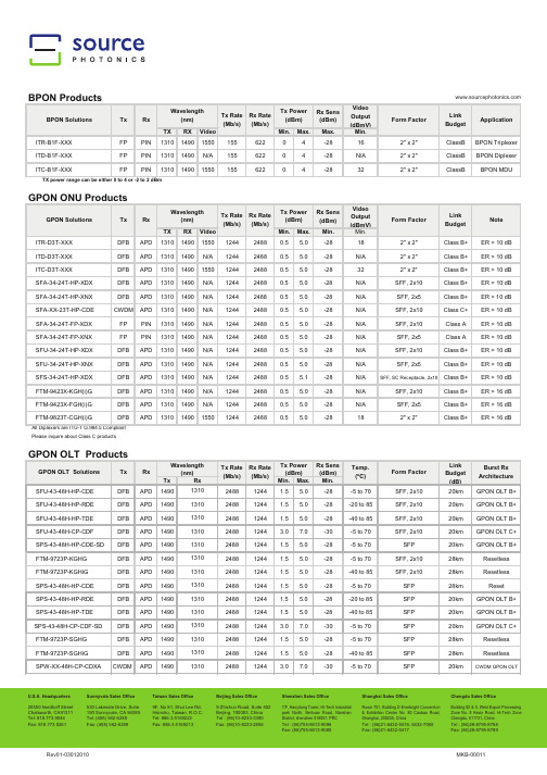
Please inquire about Class C productsU.S.A. Headquarters 20550 Nordhoff Street Chatsworth, CA91311Beijing Sales Office 9 Zhichun Road, Suite 502 Beijing, 100083, China Shenzhen Sales Office7/F, Haoyitong Tower, Hi-Tech Industrial park North, Beihuan Road, Nanshan Shanghai Sales OfficeRoom 701, Building D Everbright Convention & Exhibition Center No. 80 Caobao Road, Chengdu Sales OfficeBuilding #2 & 5, West Export Processing Zone No. 8 Kexin Road, Hi-Tech Zone Sunnyvale Sales Office 530 Lakeside Drive, Suite 190 Sunnyvale, CA 94085Taiwan Sales Office 9F, No 81, Shui Lee Rd. Hsinchu, Taiwan, R.O.C.U.S.A. Headquarters 20550 Nordhoff Street Chatsworth, CA91311Beijing Sales Office 9 Zhichun Road, Suite 502 Beijing, 100083, China Shenzhen Sales Office7/F, Haoyitong Tower, Hi-Tech Industrial park North, Beihuan Road, Nanshan Shanghai Sales OfficeRoom 701, Building D Everbright Convention & Exhibition Center No. 80 Caobao Road, Chengdu Sales OfficeBuilding #2 & 5, West Export Processing Zone No. 8 Kexin Road, Hi-Tech Zone Sunnyvale Sales Office 530 Lakeside Drive, Suite 190 Sunnyvale, CA 94085Taiwan Sales Office 9F, No 81, Shui Lee Rd. Hsinchu, Taiwan, R.O.C.ITR SFF GEPON ONU SFF GPON OLTSource Photonics is a leading provider of fiber optic components used in telecommunication systems and data communication networks. Source designs, manufactures, and sells a broad portfolio of optical communication products, including passive optical network, or PON, subsystems, optical transceivers used in the enterprise, access, and metropolitan segments of the market, as well as other optical components, modules, and subsystems. In particular, Source products include optical subsystems used in fiber-to-the-premise, or FTTP, deployments which many telecommunication service providers are using to deliver video, voice, and data services.Contact: 。
PHS-4型智能酸度计
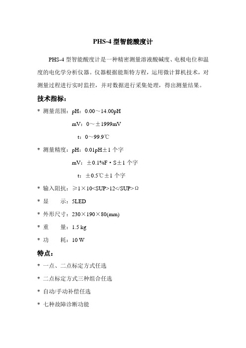
PHS-4型智能酸度计
PHS-4型智能酸度计是一种精密测量溶液酸碱度、电极电位和温度的电化学分析仪器。
仪器根据能斯特方程,运用微计算机技术,对测量过程进行实时监控,并对数据进行采集处理,得出测量结果。
技术指标:
* 测量范围:pH:0.00~14.00pH
mV:0~±1999mV
t:0~99.9℃
* 测量精度:pH:0.01pH±1个字
mV:±0.1%F·S±1个字
t:±0.5℃±1个字
* 输入阻抗:≥1×10<SUP>12</SUP>Ω
* 显示:5LED
* 外形尺寸:230×190×80(mm)
* 重量:1.5 kg
* 功耗:10 W
特点:
* 一点、二点标定方式任选
* 二点标定方式三种组合任选
* 自动/手动补偿任选
* 七种故障诊断功能
备注:
仪器可与本公司生产的各种离子选择电极、各种参比电极、磁力搅拌器等配套使用。
三汇示波器说明书(Ver1.0)
DST4000 和 DST1000 系列数字存储示波器用户手册
i
目录
5.1 显示区 ........................................................................................ 20 5.2 信息区域..................................................................................... 23 5.3 波形显示..................................................................................... 23
三汇系列产品
DST4000 和 DST1000 系列 数字存储示波器
Version 1.0
杭州三汇科技有限公司 www.
目录
目录
目 录 ...........................................................................................................i 版权申明 .......................................................................................................................................................................v 第 1 章 安全事项......................................................................................... 1
MSK4300中文资料

ISD=10A, di/dt=100A/µS
-
MSK 4300H 3 Min. Typ. Max.
2.5
8
12.5
15
5.75 6.6
7.5
6.2
7.1
8.0
-
-
0.8
2.7
-
-
60
100 135
-1
-
+1
70
-
-
-
-
25
-
-
0.300
-
-
0.16
-
5
-
-
6
-
-
0.5
2
-
5
8
-
5
8
-
0.5
2
6.0
7.0
-
SWR Resistor=∞
4
SWR Resistor=∞
4
SWR Resistor=∞
4
SWR Resistor=∞
4
SWR =∞
4
Dead Time
SWR=12K
4
SOURCE-DRAIN DIODE CHARACTERISTICS
Байду номын сангаас
Forward Voltage
1
ISD=10A
-
Reverse Recovery Time 1
-
Low Level Input Current 1
VIN=0V
-
High Level Input Current 1
VIN=5V
-
OUTPUT BRIDGE
Drain-Source Breakdown Voltage 1 ID=25µA, All Inputs Off
Liquistation CSF48 自动水质采样仪 操作手册说明书

Products Solutions Services操作手册Liquistation CSF48自动水质采样仪BA00443C/28/ZH/26.22-00715909232022-09-16自下列版本起生效01.12.01Liquistation CSF48目录Endress+Hauser 3目录1文档信息 (4)1.1安全图标 (4)1.2信息图标 (4)1.3设备上的图标 (4)1.4文档资料 (4)2基本安全指南 (6)2.1人员要求 (6)2.2指定用途 (6)2.3工作场所安全 (6)2.4操作安全 (7)2.5产品安全 (8)3产品描述 (9)3.1产品设计 (9)3.2设备结构 (11)3.3接线端子分配 (12)4到货验收和产品标识 (13)4.1到货验收 (13)4.2产品标识 (13)4.3储存和运输 (14)4.4供货清单 (14)5安装 (15)5.1安装要求 (15)5.2设置仪表 (20)5.3通过流通式安装支架采样 (23)5.4安装后检查 (23)6电气连接 (24)6.1连接传感器 (25)6.2连接采样仪控制器 (28)6.3将信号发射器连接至报警继电器 (31)6.4连接通信 (32)6.5连接附加输入、输出或继电器 (38)6.6接通电源 (41)6.7特殊接线指南 (44)6.8硬件设置 (44)6.9确保防护等级 (45)6.10连接后检查 (46)7操作方式 (47)7.1操作方式概述 (47)7.2操作菜单的结构和功能 (47)7.3通过现场显示单元访问操作菜单 (49)8系统集成 (51)8.1将采样仪集成至系统中 (51)9调试..............................559.1功能检查............................559.2设置显示语言........................559.3设置测量设备........................5510操作..............................6010.1显示界面............................6010.2常规设置............................6110.3采样方式............................7710.4输入..............................11410.5输出..............................11910.6附加功能...........................12611诊断和故障排除..................14411.1常见故障排除.......................14411.2现场显示单元上的诊断信息.............14511.3通过网页浏览器查看诊断信息...........14511.4通过现场总线查看诊断信息.............14511.5调整诊断信息.......................14511.6诊断信息概述.......................14711.7待解决诊断信息.....................15511.8诊断信息列表.......................15511.9事件日志...........................15611.10设备信息...........................16011.11复位设备...........................16711.12固件更新历史.......................16812维护.............................17212.1维护任务...........................17213维修.............................18313.1备件..............................18313.2返厂..............................18313.3处置..............................18314附件.............................18414.1设备专用附件.......................18414.2系统产品...........................18715技术参数.........................19115.1输入..............................19115.2输出..............................19115.3通信协议参数.......................19515.4电源..............................19615.5性能参数...........................19715.6环境条件...........................19815.7过程条件...........................19915.8机械结构...........................199索引. (201)文档信息Liquistation CSF484Endress+Hauser1 文档信息1.1 安全图标1.2 信息图标附加信息,提示允许推荐禁止或不推荐参考设备文档资料参考页面参考图 操作结果1.3 设备上的图标参见设备文档资料此类产品不可作为未分类城市垃圾废弃处置。
SPS-3610系列使用手册-cn

1 索引 页次1.产品介绍................................................................ 1 2产品规格................................................................ 2 2-1.一般规格............................................................. 2 2-2.定电压操作........................................................ . 3 2-3.定电流操作......................................................... 3 2-4.数位式指示表头................................................... 3 2-5.过电压保护......................................................... 3 2-6.绝缘度............................................................... 3 3.动作原理................................................................ 4 4.面板介绍................................................................ 7 4-1.前面板............................................................... 7 4-2.后面板............................................................... 7 5.操作说明................................................................10 5-1.使用前注意事项...................................................10 5-2.设定限流值.........................................................10 5-3.定电压/定电流之交越特性.......................................11 5-4.操作模式............................................................12 6一般维修................................................................13 6-1.保险丝之更换......................................................13 6-2.电源电压变换......................................................13 6-3.校正方法............................................................14 6-4.清洁方法 (15)1产品介绍本系列产品是属于仪器用的交换式直流电源供应器,改善了传统线性式电源供应器体积大、重量重、和效率差的缺点。
SPS控制器安装操作手册
目录
第一部分 概述 ...................................................................... 3 1.1 安全与警示 ........................................................................ 3 1.2 如何使用本手册 ................................................................... 4 1.3 系统安装前检查与确认…………………………………………………………………………… 5 第二部分 太阳能电源系统安装......................................................... 2.1 安装前的准备 ...................................................................... 5 2.2 太阳能电池组件方阵的安装.......................................................... 6
警示!
不要将金属类的工具放在蓄电池上, 这样造成短路产生火花导致电池损坏。
警示!
注意接线正确,防止正负极短路,否 则会导致电击或着火。
警示!
太阳能电源系统含有危险电压。
2
控制器中的控制单元可能具有潜在的致命电 压,这些电压是由于太阳能电池方阵以及蓄 电池组造成的。
安装方阵支架时,因支架构件碰撞或工具跌 落有伤人员的危险,应配戴安全帽。
5
2.3 太阳能方阵的安装
2.2.1 方阵基础的安装
CMG-40TDE说明书

CMG-40TDE一体化地震仪培训资料目录1. CMG-40TDE总体介绍 (3)1.1 开箱检查 (5)1.2 接口介绍 (5)1.3 CMG-40TDE初始化 (6)1.3.1 通过网页初始化IP地址设置 (6)1.3.2 通过超级终端初始化IP地址设置 (9)1.3.3 SCREAM软件设置 (11)1.3.3 GPS信号检查 (14)1.3.4 数据存储介质 (15)2. CMG-40TDE安装 (18)2.1山洞安装环境 (18)2.1.1 地点选择 (18)2.1.2 温度稳定性 (19)2.2坑体式安装环境 (20)2.3其他安装环境 (21)2.4具体安装步骤 (23)3. CMG-40TDE传感器部分 (30)3.1 地震计标定 (30)4. CMG-40TDE数据采集器部分 (35)4.1 数据采集器使用 (35)4.1.1 配置窗口 (35)4.1.2 控制窗口 (37)4.2 数据采集器升级 (38)5. CMG-40TDE通信单元部分 (40)5.1 IE浏览器控制和配置数据采集器 (41)5.2 NTP方式对数据采集器授时 (42)5.3 CMG-EAM在线远程升级 (45)6. SCREAM软件 (47)6.1 SCREAM软件主窗口 (47)6.2 波形显示窗口 (49)6.3 SCREAM文件设置 (50)7.问题及解决 (53)8. 接口定义 (55)1. CMG-40TDE总体介绍CMG-40TDE是便携式一体化地震仪,其密封的不锈钢外壳内包含了一个三分向宽频带负反馈地震计、一个24位数据采集器以及一个功能灵活的数据通信和存储单元。
仪器接上电源就是一个完整的测震系统。
图 1CMG-40TDE坚固防水的不锈钢外壳设计非常方便野外安装。
由于传感器内部采用轻便耐用的部件,地震计不需要锁摆,只需要加电,地震计就可以马上记录地面的运动。
此外,地震计在水平平面3度以内不需要重新调零。
德国spieth 防松螺母 夹紧套件 技术参数

德国spieth 防松螺母夹紧套件技术参数spieth防松螺母具有 MSR MSA MSF MSW MSW5中系列不同领域行业均有适配的螺母可以使用。
斯皮思防松螺母是具有高质量锁定系统(优质螺纹锁紧)的精密螺母。
具有斯皮思原理的斯皮思防松螺母可以精确地设置到机械工程中的苛刻任务,具有高的精度,甚至可以在螺纹侧面施加夹紧力。
斯皮思防松螺母用于机械工程的所有领域。
精度、可靠性、刚性和易用性是螺纹连接设计的关键方面。
每当需要至少一个方面时,斯皮思螺母始终是选 - 例如:用于切屑、成型和切削机床。
在搬运和自动化技术方面。
在输送机技术中。
一般驱动技术和变速器。
在夹具结构中。
在包装机械中。
在压缩机和泵中。
在印刷机械和造纸技术方面。
在纺织机械中。
在木工机械中。
在压力机制造中。
用于混合、破碎和离心的工艺技术。
具有测量、控制和测试技术。
防松螺母系列 MSR 可以自由、无限和精确地定位。
可靠的锁定,无需额外的凹槽或锁定板。
快速精确的组装和拆卸。
MSR型号订货型号展示MSR 10-0.75 K-10101001MSR 10x1 K-10101002MSR 12x1 K-10101201MSR 12x1.5 K-10101202MSR 14x1.5 K-10101401MSR 15x1 K-10101501有关型号的尺寸信息和图纸信息的请联系汉达森负责人刘超防松螺母系列 MSAMSA系列防松螺母的接触面减小,其中一些外径比MSR系列小,特别适用于角球轴承和圆柱滚子轴承(ISO直径系列9)的装配MSA系列部分型号订货型号展示MSA 20x1 K-10202001MSA 25x1.5 K-10202501MSA 30x1.5 K-10203001MSA 35x1.5 K-10203501MSA 40x1.5 K-10204001MSA 45x1.5 K-10204501MSA 50x1.5 K-10205001MSA 55x1.5 K-10205501MSA 60x1.5 K-10206001MSA 65x1.5 K-10206501MSA 70x1.5 K-10207001MSA 75x1.5 K-10207501有关型号的尺寸信息和图纸信息的请联系汉达森负责人刘超spieth 夹紧套件:精确施加压力斯皮思夹紧装置和夹紧元件用于机械工程的所有领域,在这些领域中,高质量和可靠的连接对机器/系统的功能起着决定性作用。
METTLER TOLEDO MT-SICS HB43-S 用户手册说明书

Reduce Your Risk of Repetitive InjuryFeel the Difference with Rainin LTSE r g o n o m i c P i p e t t i n gLTS ™ LiteTouch ™ System Reduce your risk of injury Reduce tip ejection force Reduce pain and fatigue Increase productivity Improve performance2Not only is pipetting a forceful activity – it is repetitive, and minor stresses caused by strain and overuse accumulate over time and can develop into injuries.The LTS LiteTouch SystemBecause Pipetting Shouldn’t HurtE r g o n o m i c P i p e t t i n gThe ergonomic aspects of pipetting are easily overlooked, particularly among younger and less-experienced users. However, loading and ejecting tips, and aspirating and dispensing liquids – over and over and over – exerts considerable force on your thumb, hand and arm. The injurious effects of those forces accumulate over time, which is why your risk of developing a repetitive strain injury (RSI) increases throughout your career.How often have you spent hours in the laboratory, pipetting more samples than you care to count, only to find your hand sore or wrist aching? Pipettes are integral to many laboratory workflows, so it makes sense to pay close attention to their design and features, which significantly affect your performance and the level of strain they put on your hands and arms.In addition to good accuracy and precision, a pipette’s ergonomic features are essential if you want to minimize fatigue and your risk of developing a RSI. No aspect of pipetting exerts more force on a user’s hand than tip ejection, which is why the Rainin LTS™LiteTouch™ tip ejection system by METTLER TOLEDO is so unique. LTS reduces tip ejectionforce by up to 80% and is available on all Rainin XLS+ single and multichannel pipettes.significantly reduces friction4E r g o n o m i c P i p e t t i n gPipetting is known to increase the risk of hand fatigue and RSI, resulting in a significant loss of pipetting accuracy and precision. Rainin pipettes with LTS help increase reliability and productivity.With light springs and as little as 0.6 Newtons of force required for tip ejection, LTS-equipped pipettes reduce fatigue and allow you to concentrate on your work and pipetting technique.Less Pain = Higher ProductivityLess Fatigue = More Reproducible DataRainin E4 XLS+ electronic multichannels with LTS further simplify and streamline workflows.Because LTS tips load effortlessly and achieve firm, leak-free seals without rockingor hand tightening, all Rainin multichannels are equipped with LTS.5Is Pipetting Bad for Your Health?It has been understood for many years that prolonged pipetting can lead to physical pain and muscular disorders. In fact, pipetting more than one hour per day, or roughly 300 hours per year, is linked to injury.1 The chart below describes the cumulative effects of repetitive strain injuries.1Bjørksten 1994, David & Buckle 19956E r g o n o m i c P i p e t t i n gWith LTS-equipped Rainin XLS+ pipettes, you’ll experience comfort and performance, even after hours of pipetting. Rainin pipettes equipped with the patented LTS tip ejection system not only minimize fatigue and significantly reduce the likelihood of developing RSIs, but like all Rainin XLS+ pipettes, they feature:• Ergonomically designed, lightweight bodies that fit comfortably in your hand.• A finger hook to support the pipette in your hand so you can relax your grip.•Light springs and low-drag seals for low plunger forces during aspiration and dispense.For complete pipetting control and ease, all Rainin XLS+ pipettes feature a “stiction-less” sealing systemthat allows the plunger to slide smoothly from start to finish. Corrosion-resistant plastic tip ejectors made of high quality PVDF polymer can be removed with a single-hand motion for easy cleaning. And the entire liquid end of every XLS+ pipette – shaft, seal assembly/spring and tip ejector – can be autoclaved for easy sterilization.Rainin XLS + pipettes equipped with the patented LTS LiteTouch Systemcombine proven accuracy with exceptional comfort and performance.Rainin XLS + Pipettes with LTS XLS for accuracy, LTS for comfortTotal hand comfortWith sure-fit handles, contoured finger-hooks, lighter springs and low-drag seals, Rainin XLS+ pipettes are so light and comfortable, using them all day won’t contribute to pain or discomfort.Greater controlXLS+ multichannels are among the easiest and the mostresponsive pipettes you’ll ever use. Lightweight and extraordinary channel-to-channel consistency assures smooth operation from start to finish.Easy operationFor serial dilutions, filling plates, pipetting unusual liquids and performing complex pipetting steps, the electronic E4’s versatile range of pipetting modes offer maximum convenience.Robotic production Automating our Class 100,000 clean room tip manufacturing facility has eliminated humanPipetting 360°Your Complete Liquid Handling SolutionYou maximize the performance of your Rainin pipettes andthe reliability of your results when you use BioClean Ultra ™ tips and Rainin Service by METTLER TOLEDO.BioClean Ultra TipsDesigned and engineered for Rainin pipettes and manufactured in aClass 100,000 facility, BioClean tips are guaranteed to deliver flawless, contamination-free performanceSuperior ServiceFactory-trained technicians, ISO accredited facilities and state-of- the-art balances are just a few of the reasons to choose Rainin Service by METTLER TOLEDO for pipette calibration and repair.Rainin, Pipetting 360°, Pipetting 360° logo, XLS, XLS+, LTS, LiteTouch, BioClean and BioClean Ultra are trademarks of Mettler-Toledo Rainin, LLC.For more information/raininMETTLER TOLEDO Group Laboratory DivisionLocal contact: /contactsSubject to technical changes© 03/2018 METTLER TOLEDO. All rights reserved.17700829 Rev F Rainin MarCom。
LH-HPES系列高精度环境传感器说明书

高精度环境传感器说明书适用型号:LH-HPES系列修订记录:目录1.产品介绍 (3)2.规格参数 (3)3.产品尺寸 (4)4.485通信协议与数据格式 (4)4.1.通讯基本参数 (4)4.2.数据帧格式定义 (5)4.3.功能码说明 (5)4.4.寄存器地址 (6)4.5.参数读取 (6)5.线序定义 (7)6.售后服务 (8)6.1.售后服务承诺 (8)6.2.免责声明 (8)6.3.联系方式 (8)1.产品介绍LH-HPES系列高精度环境传感器是我司推出的高精度、高可靠性、耐湿度环境传感器。
产品采用瑞士进口温湿度传感器、双通道二氧化碳传感器及高精度亮度传感器。
内置进口意法半导体芯片,并采用了高可靠性防护电路设计,内置多重防水保证高湿度环境的可用性。
产品响应速度快,性能稳定可靠,采用标准ModbusRTU通讯协议,可接入现场数显表、PLC、变频器、工控主机等设备。
产品广泛适用于高标农田、蔬菜大棚、食用菌培养、酿造发酵、食品储藏、地铁停车场、畜牧业养殖。
2.规格参数3.产品尺寸4.485通信协议与数据格式4.1.通讯基本参数4.2.数据帧格式定义采用Modbus-RTU通询规约,格式如下:地址码=1字节功能码=1字节数据区=N字节错误校验=16位CRC码结束结构>=4字节的时间地址码:为设备的地址,在通询网络中是唯一的。
功能码:主机所发指令功能提示。
数据区:数据区是具体通询数区,注意16bits数据高字节在前。
CRC码:二字节的校验码。
地址码功能码寄存器起始地址寄存器长度校验码低位校验码高位问询1字节1字节2字节2字节1字节1字节地址码功能码有效字节数数据区校验码低位校验码高位应答1字节1字节1字节2字节1字节1字节4.3.功能码说明4.4.寄存器地址寄存器地址表适用于本系列各个型号产品,请根据所购型号选择对应的寄存器。
(特别注意:使用PLC设备读取时,需要将寄存器加1,如:使用03功能码读取0001寄存器,需要写入40002)4.5.参数读取(1)例:读取设备地址为01的传感器温湿度主机发送:010*********C40B设备响应:0103040106023F5A BE注释:将返回的十六进制数据转换成十进制除以10,即可得到相应的温湿度值。
SE431中文资料

DescriptionThe SE431 is a low voltage three terminal adjustable shunt regulator with a guaranteed thermal stability over applicable temperature ranges. The output voltage can be set to any value between V REF (approximately 2.5 V) to 18V with two external resistors. This device has a typical output impedance of 0.2Ω. Active output circuitry provides a very sharp turn on characteristic, making this device excellent replacement for Zener diodes in many applications.The SE431 is characterized for operation from 0o C to 105o C, and five package options (SOT-23-3, SOT-23-5, SOP-8, TO-92 and SOT-89) allow the designer the opportunity to select the proper package for their applications. Features¾Low voltage operation (2.5V)¾Adjustable output voltage V0 = V REF to 18V¾Wide operating current range 120µA to 100mA ¾Low dynamic output impedance 0.2Ω (Typ.). ¾Trimmed bandgap design up to + 0.5%.¾ESD rating is 5.5KV(Per MIL-STD-883D).¾Available in Lead Free Packages.Application¾ Linear Regulators¾ Adjustable Supplies¾Switching Power Supplies¾Battery Operated Computers¾ Instrumentation¾ Computer Disk DrivesBlock DiagramSymbol DiagramPin ConfigurationSOT-23-3 SOT-23-3L (SC59-3L)SOT-23-3 (Order as SE431S)SOT-23-5LSOP-8TO-92(Top View)SOT-89Marking InformationPackage Marking Production Year CodeProduction Week CodeLead-Free PackageSOT-23-3 SC59-3L SE431W SOT-23-3 S431W (SE431S) SOT-23-5L SE431W Starting with S, a bar on top of S is for production year 2001, and underlined S is for year 2002. The next character is marked on top for 2003, and underlined for 2004. The naming pattern continues with consecutive characters for later years.A-Z: 1-26 a-z: 27-52Lead-free package is indicated by a dot on top of the week code.SOP-8SE431 YYWW SOT-89SE431 YYWW TO-92SE431 YYWWYY is the year of production. 04 means the product is manufactured in year of 2004. WW is the week ofproduction. 26 means theproduct is manufactured inthe 26th week.Lead-free package isindicated by LF afterYYWW.Absolute Maximum Ratings Parameter Symbol Maximum UnitsCathode VoltageV KA 18 V Continuous Cathode CurrentI KA 150 mA Reference CurrentI REF 10 mA Operating Junction Temperature RangeT J 150 °C Storage Temperature RangeT STG -65 to 150 °C 120 (SOT-89) 230 (SOT-23-3)230 (SOT-23-5L) 150 (SOP-8) Thermal Resistanceθ JA220 (TO-92)°C/WLead Temperature (Soldering) 10 seconds T LEAD 260 °CElectrical CharacteristicsPARAMETER SYMBOLTESTCIRCUITTEST CONDITIONSMINTYPMAXUNIT0.5%2483 2495 25071% 2470 2495 2520Reference Voltage2%V REF 1 V KA = V REF , I KA = 10mA2445 2495 2545mVDeviation of reference voltage overfull temperature range V I(dev) 1V KA = V REF , I KA = 10mAT A = 0°C to 105°C -- 4 25 mVRatio of change in reference voltage to the change in cathodevoltage ∆ V REF ________ ∆ V KA2I KA = 10mA,∆V KA = 10 V - V REF-- -1.4 -2.7 mV/VReference current I REF 2I KA = 10mA,R1=10k Ω, R2 = ∞-- 2 4 µADeviation of Reference current over full temperature range I I(dev) 2I KA = 10mA, R1=10k Ω,R2 = ∞, T A = 0°C to 105°C-- 0.4 1.2 µA Minimum cathode current forregulationI MIN 1V KA = V REF -- 0.2 1 mAOff-state cathode current I OFF3 V KA = 18V, V REF = 0--0.11µADynamic impedanceZ KA 1I KA = 1mA to 100mA, V KA =V REF , f ≤ 1kH Z-- 0.2 0.7 ΩTypical Performance Characteristics-200200400600800-1123CATHODE CURRENTC a t h o d e C u r r e n t (µA )Cathode Voltage (V)CATHODE CURRENTVs.Application DiagramV IN)Thermal ConsiderationPackage Power Rating (T A =25°C )Power Rating(T A =50°C )Power Rating (T A =70°C )SOT-23-3 (θJA =230°C/W) 435mW 326mW 239mW SOT-23-5L (θJA =230°C/W) 435mW 326mW 239mW TO-92 (θJA =220°C/W)455mW 341mW 250mW1. Maximum junction temperature is 125°C2. θJA is measured with packages mounted onboard under still-air condition with 1W power applied.3. Power rating is calculated using P D = (T J – T A ) /θJA, where T J denotes junction temperature and T A denotes ambient temperature.OUTLINE DRAWING SOT-23-3OUTLINE DRAWING SOT-23-5LOUTLINE DRAWING SC59-3L (SOT-23-3L)OUTLINE DRAWING SOP-8OUTLINE DRAWING TO-92OUTLINE DRAWING SOT-89Customer SupportSeaward Electronics Incorporated – ChinaRm 1605, Building 1, International Pioneering Park, #1 Shangdi Xinxi Rd Haidian District, Beijing 100085, ChinaTel: 86-10-8289-5700/01/05Fax: 86-10-8289-5706Seaward Electronics Corporation – Taiwan2F, #181, Sec. 3, Minquan East Rd,Taipei, Taiwan R.O.CTel: 886-2-2712-0307Fax: 886-2-2712-0191Seaward Electronics Incorporated – North America49 Showers Dr. J126Mountain View, CA 94040, USATel: 1-408-821-6600Last Updated - 3/23/2005。
MSP430F4XX中文技术手册

– MSP430F412: 4KB + 256B Flash Memory,256B RAM;
– MSP430F413: 8KB + 256B Flash Memory,256B RAM;
专业音频术语中英文对照(S-W)

Sweep 扫描,曲线
Swell 增音器
Swing 摆幅,摇摆舞
Swishing 飕飕声
SX simplex 单工
SXE stereo exciter 立体声激励器
Symphobass 调谐低音系统
Symphonic 交响,谐音
SYS Ex system expanding 系统扩展
Sound field 声场
Sound image 声像
Sound intensity 声强
Sound shadow region 声影区
Sound cousole desk 调音台
Source 声源
SOS sound on sound 叠加录音
SP speaker 扬声器
SP speed 速度
Slap 拍打效果
Slap back 山谷回声
Slap reverb 山谷混响效果
Slate 预定,标记,(录音调音台)标记开关
Slave 从属的,从机,从动的
Sleep 睡眠定时开关,静止
Sleeve(SLE) 接地点,袖端,套
Slew rate 瞬态率
Sliding tone 滑音
SIF 伴音中频
Silencer 静噪器
Silent 静噪调谐
Simple tone 纯音
Simplex 单工
Simulate 模拟的
Simultaneous 同步,联立
SINAD signal to noise and distortion ratio
信号对噪声和失真比
Sine wave 正弦波
海德福斯 电比例阀(中文)
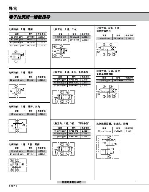
型号 PV08-31 PV70-31 PV72-31 PV76-31
手册页码 2.380.1 2.382.1 2.384.1 2.386.1
比例流量控制,常开
流量 38 lpm/10 gpm 87 lpm/23 gpm
型号 PV70-35 PV72-35
手册页码 2.432.1 2.434.1
比例流量控制,旁通,常闭
流量 22 lpm/6 gpm 30 lpm/8 gpm 64 lpm/17 gpm 151 lpm/40 gpm
型号 PV08-30 PV70-30 PV72-30 PV76-30A
手册页码 2.370.1 2.372.1 2.374.1 2.376.1
比例流量控制,旁通,常闭
流量
型号
手册页码
190 lpm/50 gpm PV42-M30 2.378.1
缩写符号:
比例压力控制,先导溢流,电流增 大压力增大
流量 95 lpm/25 gpm 189 lpm/50 gpm
型号 TS10-26 TS12-26
手册页码 2.852.1 2.854.1
0.002.3
截止阀 (典型)
电子比例阀—选型指导
比例压力控制,先导溢流,电流增 大压力减小
流量 19 lpm/5 gpm 76 lpm/20 gpm 189 lpm/50 gpm
—
推荐的电子控制器
仅指 PCB 板
铁盒式
零件编号 手册页码 零件编号 手册页码
4000046 4000141 4000143 4000144
3.426.1 3.427.1 3.428.1 3.429.1
4000049 4000124 4000130 4000133
- 1、下载文档前请自行甄别文档内容的完整性,平台不提供额外的编辑、内容补充、找答案等附加服务。
- 2、"仅部分预览"的文档,不可在线预览部分如存在完整性等问题,可反馈申请退款(可完整预览的文档不适用该条件!)。
- 3、如文档侵犯您的权益,请联系客服反馈,我们会尽快为您处理(人工客服工作时间:9:00-18:30)。
General Operating Parameter Operating Voltage Total Supply Current Case Operating Temerature (-CDE) Case Operating Temerature (-RDE) Case Operating Temerature (-TDE) Storage Temperature Symbol Vcc ICC Topr Topr Topr Tstg Min. 3.135 -5 -20 -40 -40 Typ. 3.3 Max. 3.465 500 70 85 85 85 Unit V mA ºC ºC ºC ºC
f
Symbol Vout,p-p tr tf V_DETH V_DETL T_BRST_Det
Min 250 2.4 0 -
Typical 250 250 -
Max 800 Vcc 0.4 6.4
Unit mV ps ps V V nS
BRST_Det Response Time
e) 20% to 80% values f) BRST_Det assert low when module receive “reset” signal, assert high when incoming burst is detected and latch to high state until next “Reset” signal. Digital RSSI Timing Specification Parameter RSSI Trigger Delayg RSSI Sampling Time
LUMNDS2036-FEB1108 rev. 0.2 SHORT FORM
2
元器件交易网1490nm/1310nm Single Fiber OLT Transceiver
Preliminary Datasheet
SPS-43-48H-HP-xDE (x=C, R, T)
c) At 10-10 BER with PRBS 223-1 data d) The input power difference between two subsequent high and low burst data. Receiver Specifications (Electrical) Parameter PECL Single ended data output swing(LVPECL) Data output rise timee Data output fall timee BRST_Det_Highf BRST_Det_Low
20550 Nordhoff St. • Chatsworth, CA 91311 • tel: 818.773.9044 • fax: 818.576.9486 9F, No 81, Shui Lee Rd. • Hsinchu, Taiwan, R.O.C. • tel: 886.3.5169222 • fax: 886.3.5169213
g g
Symbol TTrigger RSSISample TI2C RXDDM
Min 25 300 -
ห้องสมุดไป่ตู้
Typical -
Max 500 +/- 3
Unit nS nS µS dB
Internal I2C Delay Reciever Power DDM (RSSI) Errorh
g) RSSI_ACQ Input signal rising edge will trigger RSSI sampling, and falling edge will trigger internal digital RSSI information written to I2C. It is recommended that host shall not trigger RSSI_ACQ input again until RSSI data is valid in I2C from previous RSSI trigger. h) RSSI DDM working range is between -8 to -30 dBm. RSSI DDM accuracy is better than +/- 3dB for input power levels between -10 to -30 dBm, the accuracy reduces to +/- 5dBm for power levels larger than -10dBm. 20550 Nordhoff St. • Chatsworth, CA 91311 • tel: 818.773.9044 • fax: 818.576.9486 9F, No 81, Shui Lee Rd. • Hsinchu, Taiwan, R.O.C. • tel: 886.3.5169222 • fax: 886.3.5169213
LUMNDS2036-FEB1108 rev. 0.2 SHORT FORM
1
元器件交易网1490nm/1310nm Single Fiber OLT Transceiver
Preliminary Datasheet
SPS-43-48H-HP-xDE (x=C, R, T)
元器件交易网1490nm/1310nm Single Fiber OLT Transceiver
Preliminary Datasheet
SPS-43-48H-HP-xDE (x=C, R, T)
Features • Burst receive GPON OLT transceiver • Small Form Factor Pluggable, Simple SC Connector • “Fast Signal Detect” feature reduces ranging overhead • Simplifed OLT “reset” timing • 1490 nm DFB Tx with isolator • 1310 nm APD Rx • 2488 Mbps downstream Tx/1244 Mbps upstream Rx • Single 3.3 V supply • ITU-T G.984.2 compliant • 20 km reach; 28 dB link budget • RoHS-5/6 compliant (lead exemption)
Pinout Definitions Pin 1 2 3 4 5 6 7 8 9 10 11 12 13 14 15 16 17 18 19 20 Function Veet Tx_Fail (Tx_Fault) TX_DIS MOD_DEF (2) MOD_DEF (1) MOD_DEF (0) Reset BRST_Det RSSI_ACQ Veer Veer RXDRXD+ Veer Vcc_RX Vcc_TX Veet TXD+ TXDVeet Notes Tx Ground Tx Fail Alarm. LVTTL Output Active High Tx Disable. LVTTL input. Laser output is disabled when this pin is asserted high or left unconnected. Laser output is enabled when this pin is asserted low. 2-Wire Serial Data I/O Pin. 2-Wire Serial Clock Input. Internally Grounded CMOS input. Assert “Reset” high at the end of previous burst, 2 bytes in duration LVTTL output. BRST_Det assert low when module receives “reset” signal, assert high when incoming burst is present. RSSI acquire/hold LVTTL Input. Digital RSSI output through I2C Rx Ground Rx Ground Negative Data Output, LVPECL; DC coupled Positive Data Output, LVPECL; DC coupled Rx Ground Rx Vcc Tx Vcc Tx Ground Positive Data Input, LVPECL or CML (AC coupled; internally 100 ohms differential termination) Negative Data Input, LVPECLor CML (AC coupled; internally 100 ohms differential termination) Tx Ground
Unit dB dB dB
Transmitter Specifications (Optical) Parameter Optical Power Average launch power of off Tx Wavelength Spectral Width (-20 dB) Side Mode Suppression Ratio Extinction Ratio Transmit eye mask Bit Rate Optical Rise timea Optical Fall timea Tolerence to TX back reflectionb a) 20% to 80% values b) 1 dB degradation of receiver sensitivity -15 2488 Symbol Pop Poff λ ∆λ20 SMSR ER Min 1.5 1480 30 10 Typical 1490 G.984.2 160 160 Mbps ps ps dB Max 5 -40 1500 1 Unit dBm dBm nm nm dB dB
