C1410CUA中文资料
宜准电子科技WPC400和PVC410宽量程皮拉尼潘宁复合真空计说明书

操作手册宜准电子,让真空测量更简单!INSTRUE , Makes Vacuum Measurement Easier.宽量程皮拉尼潘宁复合真空计WPC400 集成数显皮拉尼冷阴极真空计 PVC410 集成皮拉尼冷阴极变送规● 宽量程,覆盖大气到1.0E-5Pa 高真空检测 ● 支持本地显示,实时读取真空度数值● 特殊电极材料与结构,维护频率低,使用寿命久● 内嵌温度自动补充,消除环境温度波动对测量的干扰 ● 双传感互锁,真空计在任意真空度均可安全启动 ● 可选Pa 、Torr 、mBar 三种单位显示● 双通讯模式,同时输出模拟量与RS485-Modbus 数据通讯 ● 支持双路可编程设置开关量输出●适配GaugeReader 数据采集、配置、存储上位机软件1.型号选择集成数显皮拉尼冷阴极真空计WPC 400 X (X为真空接口,A:KF25,B:KF40,C:CF25,D:CF35) 集成皮拉尼冷阴极变送规PVC 410 X (X为真空接口,A:KF25,B:KF40,C:CF25,D:CF35) 2.参数表参数数值WPC400 PVC410测量范围 (空气, N2) 1.0×10⁻⁵ ~1.0×10+5 Pa精度1.0×10⁻⁵ ~1.0×10- 4 Pa : ±35% 1.0×10⁻⁴ ~1.0×10+4 Pa : ±25% 1.0×10+4 ~1.0×10+5 Pa : ±50%重复性1.0×10⁻⁵ ~1.0×10+3 Pa : ±5% 1.0×10+3 ~1.0×10+5 Pa : ±25%耐压(绝对压力) 1.5×10+5 Pa反应时间< 100 ms < 50 ms 工作环境0º C ~ +45º C; 5 ~ 85 %, 不结露存储环境-40º C ~ +75º C;5 ~ 90 %, 不结露信号输出5位LED显示,单位可选NA 双控制开关输出 60VDC 0.5A NARS485, 9600 bps,Modbus RTU模拟量输出+0.0V~+10.0VDC电接口DSub9公插座RJ45插座供电电源+16~+32 VDC /0.5A ;最大功耗 2.5W 防护等级IP40,IEC529真空系统连接标配 DN 25 ISO-KF;其他需定制重量与尺寸420g (KF25), 130H X 60W X50D 310g (KF25),90H X 41Dia.接触真空的材料SS304不锈钢, Kovar 4J50, 钨丝, 馈通玻璃注. 由于研发及新品推出,宜准电子保留修改该文档的权利,请与原厂保持联系!注意D-Sub 9针连接器的区别:公头,母头,焊接侧,插入侧。
F14-10中文资料
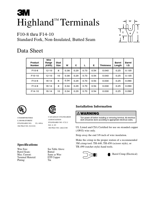
Highland ™TerminalsF10-8 thru F14-10Standard Fork,Non-Insulated,Butted SeamData SheetSpecificationsWire Size:See Table Above Barrel Seam:ButtedMax. Current:Same as Wire Terminal Material:ETP Copper Plating:TinInstallation Information UL Listed and CSA Certified for use on stranded copper (AWG) wire only.Strip away the end 3/8 inch of wire insulation.Make the crimp in the proper station of a recommended 3M crimp tool:TH-440,TH-450 (scissor style),or TR-490 (ratchet style) hand tools.Barrel Crimp (Electrical)UNDERWRITERS LABORATORIESSTANDARD NO. UL 486A 3M FILE NO. E23438CANADIAN STANDARDS ASSOCIATIONSTANDARD NO. C22.2NO. 0. 653M FILE NO. LR22190t c u d o r P re b m u N e r i W e g n a R )G W A (d u t S ez i S WCLEss e n k c i h T l e r r a B ht g n e L l e r r a B .D .I 8-01F 01-21883.092.037.045.0040.052.0531.001-01F 01-210183.092.037.045.0040.052.0531.06-41F 41-61643.092.007.045.0030.052.0090.08-41F 41-61843.092.007.045.0030.052.0090.001-41F 41-610143.092.007.045.0030.052.0090.0Electrical Products Division 6801 River Place Blvd.Austin,TX 78726-9000/elpdLitho in USA.©3M 2002 78-8126-0626-3-AIMPORTANT NOTICEBefore using this product, you must evaluate it and determine if it is suitable for your intended application.Y ou assume all risks and liability associated with such use.Warranty;Limited Remedy;Limited Liability.This product will be free from defects in material and manufacture as of the date of purchase.3M MAKES NO OTHER WARRANTIES INCLUDING,BUT NOT LIMITED TO,ANY IMPLIED WARRANTY OF MERCHANTABILITY ORFITNESS FOR A PARTICULAR PURPOSE.If this product is defective within the warranty period stated above, your exclusive remedy shall be,at 3M’s option, to replace or repair the 3M product or refund the purchase price of the 3M product.Except where prohibited by law,3M will not be liable for any loss or damage arising from this 3M product,whether direct,indirect,special,incidental or consequential regardless of the legal theory asserted.3M and Highland are trademarks of 3MEngineering SpecificationCrimp-type terminals shall,electrically andmechnically,connect to a pre-stripped end of a stranded copper wire:and have a flat tongue portion with a central opening for mounting around a screw or stud.The terminal line shall offer tongue variations in hole (stud) size (6,8 10,etc.) and configuration (ring,fork,block fork,flanged block fork,locking fork,etc.):and barrel variations in wire (AWG) size (22-18,16-14,12-10,etc.) and construction (non-insulated brazed seam,vinyl insulated butted seam,nylon insulated with insulation grip,etc.). The terminal line shall have regulatory agency coverage (UL Listing,CSACertification). The terminal tongue shall be marked with the wire range and manufacturer ’s symbol ( ).The non-insulated,butted seam standard fork terminal shall be tin-plated,annealed copper,with the tongue having a specified stud slot (size 6 thru 10) and a butted seam barrel with a beveled I.D. for ease of stranded wire entry,sized for a specified (AWG) wire range (16-14,12-10).Non-insulated terminals shall be UL Listed and CSA Certified.。
JIS C 3410(2010)中文版

JIS C 3410(2010)中文版JIS日本工业标准由日本标准协会翻译出版JIS C 3410:2010(JCMA/JSA)船舶电器用电缆和软线建立日期:1961-05-01修改日期:2010-10-25登官方公报日期:2010-10-25调查方:日本工业标准委员会;标准委员会;电力技术委员会 JIS C 3410:2010第一份英文编订版于2011年9月出版目录页引言………………………………………………………………………1 1 范围…………………………………………………………………1 2 引用规范…………………………………………………………… 2 3序这个译本是基于原日本工业标准制作的,并由经济、贸易和工业部长和土地、基础设施、运输和旅游部长修订,日本工业标准委员会通过了其审议结果。
日本电线电缆制造商协会和日本标准协会建议修订日本工业标准,他们重视草案的起草,要求在工业标准化法的12条第1条款的基础上并适用于第14条修订版的情况。
所以,JIS C 3410:1999被这个标准所取代,可以功成身退了。
JIS受版权法所保护。
值得注意的是,当专利申请对外公开后,或是当公用事业模型权利或申请登记公用事业模型对具有技术知识的民众公开后,该标准的一些部分可能与专利权发生冲突。
有关部长和日本工业标准委员会在申请专利对外公开后,或是当公用事业模型权利或申请登记公用事业模型对已经表示具有技术知识的民众公开后,都不会对鉴定专利权负责。
船舶电器用电缆和软线引言这份日本工业标准是根据2004年出版的IEC 60092-351第三版,1995年出版的IEC 60092-353第二版以及其2001年的修订第一版,2003年出版的IEC 60092-354第二版,1987年出版的IEC 60092-359第一版以及其1994年的修订第一版、1999年的修订第二版和2003年出版的IEC 60092-376第二版。
上述所提及标准的技术含量已经按日本工业标准进行了修改。
上海衬氟截止阀参数

上海衬氟截止阀参数
上海衬氟截止阀是一种阀门,使用聚四氟乙烯(PTFE)涂层的内胆和PTFE密封圈来保证其高耐腐蚀性。
下面是该阀门的一些关键参数:
1. 规格和尺寸:上海衬氟截止阀的规格和尺寸可以根据不同的使用要
求进行定制。
一般来说,该阀门的尺寸范围从DN15到DN250。
2. 温度能力:该阀门可以在高温和低温环境下使用,不受温度的影响,其温度范围从-40℃到200℃。
3. 压力等级:上海衬氟截止阀可以承受高压力和真空的要求。
根据设
计要求,其压力等级可达到PN10,PN16,PN25和PN40等级。
4. 材料:上海衬氟截止阀的材料包括铸钢、不锈钢、铜和铝等,使用
不同的材料可以满足不同场合的需求。
5. 控制方式:该阀门可使用手动操作,也可以配备电动或气动控制系统。
6. 技术标准:上海衬氟截止阀已通过各种国际标准的认证,包括ISO 9001,API 6D,CE,TA-Luft和ATEX等认证。
7. 适用范围:由于其高耐腐蚀性和高温能力,上海衬氟截止阀广泛应
用于石化、制药、电力、纺织、食品和饮料等行业中的水和气体管道
系统中。
总之,上海衬氟截止阀是一种高品质、高耐腐蚀、高温防护和多功能
的阀门,适用于各种行业的过程管道中。
在选择该阀门时,用户应考
虑其所需的温度、压力和材料等要素,并选择合适的规格和尺寸。
JIS H 3300:2009铜及び铜合金の継目无管(日文)
銅及び銅合金の継目無管JIS H 3300:2009平成21年7月20日改正日本工業標準調査会審議(日本規格協会発行)H 3300:2009 _____________________________________________________主 務 大 臣:経済産業大臣 制定:昭和52.5.1 改正:平成21.7.20 官 報 公 示:平成21.7.21 原案作成協力者:日本伸銅協会(〒110-0005 東京都台東区上野1-10-10 うさぎやビル TEL 03-3836-8801)審 議 部 会:日本工業標準調査会 標準部会(部会長 二瓶 好正) 審議専門委員会:非鉄金属技術専門委員会(委員会長 神尾 彰彦)この規格についての意見又は質問は,上記原案作成協力者又は経済産業省産業技術環境局 基準認証ユニット産業基盤標準化推進室(〒100-8901 東京都千代田区霞が関1-3-1 E-mail:qqgcbd@meti.go.jp 又はFAX 03-3580-8625)にご連絡ください。
なお,日本工業規格は,工業標準化法第15条の規定によって,少なくとも5年を経過する日までに日本工業標準調査会の審議に付され,速やかに,確認,改正又は廃止されます。
日本工業標準調査会標準部会 非鉄金属技術専門委員会 構成表氏名所属(委員会長) 神 尾 彰 彦 東京工業大学名誉教授 (委員) 木股 三 株式会社ビスキャス小 出 正 登 日本伸銅協会(三菱マテリアル株式会社) 近 藤 良太郎 社団法人日本電機工業会齋 藤 鐵 哉 独立行政法人物質・材料研究機構 下 村 孝 社団法人日本鉄道車輌工業会 田 中 護 史 財団法人日本船舶技術研究協会 田 村 泰 夫 日本鉱業協会中 野 利 彦 株式会社神戸製鋼所中 村 守 独立行政法人産業技術総合研究所 西 村 尚 東京都立大学名誉教授 林 央 独立行政法人理化学研究所 町 田 克 己 住友金属鉱山株式会社吉 田 英 雄 社団法人軽金属学会(住友軽金属工業株式会社) (専門委員) 野 原 慈 久財団法人日本規格協会H 3300:2009目 次ページ序文 (1)1適用範囲 (1)2引用規格 (1)3用語及び定義 (2)4種類,等級及び記号 (2)5品質 (3)5.1外観 (3)5.2化学成分 (3)5.3機械的性質及び物理的性質の試験項目 (5)5.4機械的性質 (8)5.5結晶粒度 (14)5.6押広げ性 (14)5.7へん平性 (14)5.8非破壊検査特性 (14)5.9導電率 (14)5.10水素ぜい性 (15)5.11時期割れ性 (15)5.12浸出性能 (15)6寸法及びその許容差 (15)6.1寸法の指定 (15)6.2代表寸法 (15)6.3寸法の許容差 (16)6.4直管の曲がりの最大値 (19)7試験 (20)7.1サンプリング (20)7.2化学分析試験 (20)7.3引張試験 (20)7.4硬さ試験 (20)7.5結晶粒度試験 (20)7.6押広げ試験 (21)7.7へん平試験 (21)7.8渦流探傷試験 (21)7.9水圧試験 (22)7.10空圧試験 (22)7.11導電率試験 (22)H 3300:2009 目次ページ7.12水素ぜい化試験 (23)7.13時期割れ試験 (23)7.14浸出性能試験 (23)8検査 (23)9表示 (24)附属書A(参考)銅及び銅合金継目無管の代表寸法 (25)解 説 (28)H 3300:2009まえがきこの規格は,工業標準化法に基づき,日本工業標準調査会の審議を経て,経済産業大臣が改正した日本工業規格である。
电压阀CPE14-M1BH-3GL-QS-8商品说明书

Hoja de datos
Característica Función de las válvulas Tipo de accionamiento Ancho Caudal nominal normal Presión de funcionamiento Mpa Presión de funcionamiento Construcción Tipo de reposición Homologación Clasificación marítima Tipo de protección
Comprobación de suplemento de transporte con grado de nitidez 2 según FN 942017-4 y EN 60068-2-6
Control de golpes con grado de severidad 2, según FN 942017-5 y EN 60068-2-27
electroválvula CPE14-M1BH-3GL-QS-8
Número de artículo: 196888 Clásico - No utilizar para equipos nuevos
alto grado de integración.
Puede encontrar alternativas modernas introduciendo las cuatro primeras partes del código del producto en el campo de búsqueda.
1/2
Característica
Tipo de fijación Conexión del aire de escape de pilotaje 82 Conexión del aire de pilotaje 12 Conexión neumática 1 Conexión neumática 2 Conexión neumática 3 Indicación sobre el material Material de las juntas Material de la carcasa
C1410中文资料
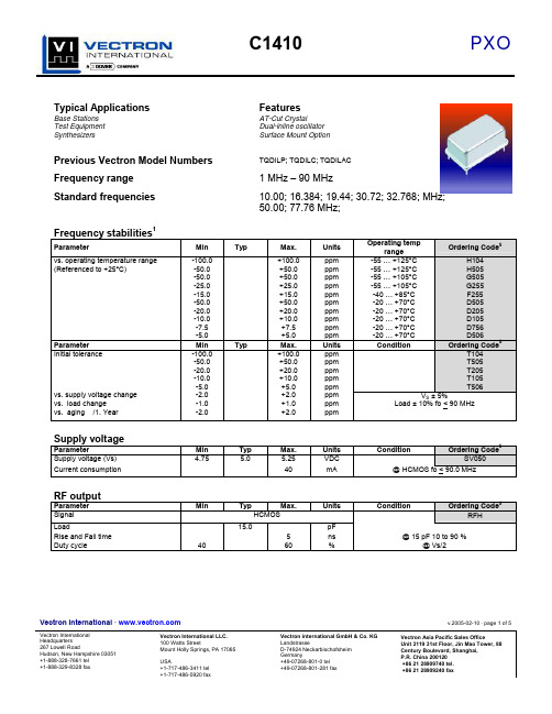
Vectron International · v.2005-02-10 · page 1 of 5Vectron International Headquarters Vectron International LLC. 100 Watts StreetVectron international GmbH & Co. KG LandstrasseVectron Asia Pacific Sales OfficeUnit 3119 31st Floor, Jin Mao Tower, 88Typical ApplicationsFeaturesBase Stations AT-Cut CrystalTest Equipment Dual-inline oscillator Synthesizers Surface Mount OptionPrevious Vectron Model NumbersTQDILP; TQDILC; TQDILACFrequency range1 MHz – 90 MHzStandard frequencies10.00; 16.384; 19.44; 30.72; 32.768; MHz; 50.00; 77.76 MHz;Frequency stabilities 1ParameterMin Typ Max. Units Operating temprange Ordering Code 5vs. operating temperature range (Referenced to +25°C)-100.0 -50.0 -50.0 -25.0 -15.0 -50.0 -20.0 -10.0 -7.5 -5.0+100.0 +50.0 +50.0 +25.0 +15.0 +50.0 +20.0 +10.0 +7.5 +5.0 ppm ppm ppm ppm ppm ppm ppm ppm ppm ppm -55 … +125°C -55 … +125°C -55 … +105°C -55 … +105°C -40 … +85°C -20 … +70°C -20 … +70°C -20 … +70°C -20 … +70°C -20 … +70°C H104 H505 G505 G255 F255 D505 D205 D105 D756 D506Parameter Min Typ Max. Units ConditionOrdering Code 5T104 T505 T205 T105 T506Initial tolerancevs. supply voltage change vs. load change vs. aging /1. Year-100.0 -50.0 -20.0 -10.0 -5.0 -2.0 -1.0 -2.0+100.0 +50.0 +20.0 +10.0 +5.0 +2.0 +1.0 +2.0ppm ppm ppm ppm ppm ppm ppm ppmV S ± 5%Load ± 10% fo < 90 MHzSupply voltageParameterMin Typ Max. Units ConditionOrdering Code 5Supply voltage (Vs)4.755.0 5.25 VDCSV050Current consumption40mA@ HCMOS fo < 90.0 MHzRF outputParameter Min Typ Max.Units ConditionOrdering Code 5SignalHCMOSRFHLoad15.0 pFRise and Fall time 5 ns @ 15 pF 10 to 90 %Duty cycle4060%@ Vs/2Vectron International · v.2005-02-10 · page 2 of 5Vectron International Headquarters Vectron International LLC.100 Watts StreetVectron international GmbH & Co. KGLandstrasseVectron Asia Pacific Sales OfficeUnit 3119 31st Floor, Jin Mao Tower, 88Additional parametersParameter Min Typ Max. Units ConditionPhase Noise -80 dBc/Hz 10 Hz @10.000-110 dBc/Hz 100 Hz MHz-135 dBc/Hz 1 kHz HCMOS-145 dBc/Hz 10 kHz 5.0 V-150 dBc/Hz 100 kHzWeight 6 gProcessing & Packing handling&processing noteVectron International · v.2005-02-10 · page 3 of 5Vectron International Headquarters Vectron International LLC.100 Watts StreetVectron international GmbH & Co. KGLandstrasseVectron Asia Pacific Sales OfficeUnit 3119 31st Floor, Jin Mao Tower, 88EnclosuresAbsolute Maximum RatingsParameter Min Typ Max. Units Condition Supply voltage (Vs) 7 VOperable temperature range -40 +80 °C For temperature Code F, D Storage temperature range -40 +90 °C For temperature Code F, DVectron International · v.2005-02-10 · page 4 of 5Vectron International Headquarters Vectron International LLC. 100 Watts StreetVectron international GmbH & Co. KG LandstrasseVectron Asia Pacific Sales OfficeUnit 3119 31st Floor, Jin Mao Tower, 88Recommended Reflow ProfileSMD oscillators must be on the top side of the PCB during the reflow process.Vectron International · v.2005-02-10 · page 5 of 5Vectron International Headquarters Vectron International LLC.100 Watts StreetVectron international GmbH & Co. KGLandstrasseVectron Asia Pacific Sales OfficeUnit 3119 31st Floor, Jin Mao Tower, 88How to Order this Product:Step 1 Use this worksheet to forward the following information to your factory representative:Model Stability Code Initial tolerance Supply Voltage Code RF Output Code Package Code C1410Example: C1410 D205 T104 SV050 RFH A1Step 2 The factory representative will then respond with a Vectron Model Number in the following Configuration: Model Package Code Dash Dash NumberC1410 [Customer Specified Package Code]- [Factory Generated 4 digit number] Typical P/N = C1410A1-0001Notes:1 Contact factory for improved stabilities or additional product options. Not all options and codes are available at all frequencies.2 Unless otherwise stated all values are valid after warm-up time and refer to typical conditions for supply voltage, frequency controlvoltage, load, temperature (25°C)3 Phase noise degrades with increasing output frequency.4 Subject to technical modification.5 Contact factory for availability.。
辽宁电动截止阀参数

辽宁电动截止阀参数
辽宁电动截止阀是一种用于控制管道流体的阀门,具有很强的控制性能和可靠性。
以下是该电动截止阀的主要参数介绍:
一、结构特点:
1.本产品结构简单、体积小、重量轻,安装方便,其结构设计满足了现代化流体控制技术的要求。
2.采用先进的电动执行器和智能化控制系统,使本产品的性能和使用寿命大大提高。
3.选用高强度不锈钢制造出的阀杆和波纹管,保证了阀门的可靠性和耐用性。
4.采用硬质合金密封材料,使其密封性能可靠,能耐高温、高压等恶劣环境。
二、主要参数:
1.公称压力:PN10~PN160
3.密封性能:零泄漏
4.安装形式:法兰式、对夹式、螺纹式等
5.介质温度:≤180℃,≤230℃,≤450℃
6.操作方式:手动、电动、气动
7.适用介质:液体、气体、蒸汽、油品等。
三、技术参数:
1.密封材料:硬质合金
2.阀杆材料:2Cr13
3.执行器电压:AC220V、AC380V
4.电动执行器功率:400W、750W、1200W等
5.打开/关闭时间:15S,60S,90S等
以上为辽宁电动截止阀的主要参数介绍,该阀门采用先进的技术和材料,设计紧凑,操作方便,能够适应各种介质和工作条件,是现代化流体控制系统的重要组成部分。
C1411CUA中文资料

TC1411/TC1411N
2.0 TYPICAL PERFORMANCE CURVES
MSOP .......................................................... 340 mW PDIP ............................................................ 730 mW SOIC............................................................ 470 mW Storage Temperature Range .............. -65°C to +150°C Maximum Junction Temperature ...................... +150°C
Parameters
Sym Min Typ Max Units
Conditions
Temperature Ranges Specified Temperature Range (C) Specified Temperature Range (E) Specified Temperature Range (V) Maximum Junction Temperature Storage Temperature Range Package Thermal Resistances Thermal Resistance, 8L-MSOP Thermal Resistance, 8L-PDIP Thermal Resistance, 8L-SOIC
TC1411/TC1411N
Functional Block Diagram
300 mV
54AC14中文资料
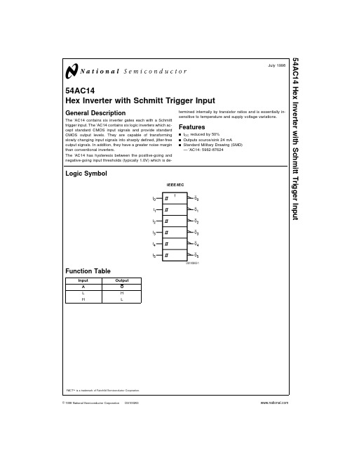
54AC14Hex Inverter with Schmitt Trigger InputGeneral DescriptionThe ’AC14contains six inverter gates each with a Schmitt trigger input.The ’AC14contains six logic inverters which ac-cept standard CMOS input signals and provide standard CMOS output levels.They are capable of transforming slowly changing input signals into sharply defined,jitter-free output signals.In addition,they have a greater noise margin than conventional inverters.The ’AC14has hysteresis between the positive-going and negative-going input thresholds (typically 1.0V)which is de-termined internally by transistor ratios and is essentially in-sensitive to temperature and supply voltage variations.Featuresn I CC reduced by 50%n Outputs source/sink 24mAn Standard Military Drawing (SMD)—’AC14:5962-87624Logic SymbolFunction TableInput Output A O L H HLFACT ™is a trademark of Fairchild Semiconductor Corporation.IEEE/IECDS100263-1July 199854AC14Hex Inverter with Schmitt Trigger Input©1998National Semiconductor Corporation Connection DiagramsPin Names Description I n Inputs O nOutputsPin Assignment for DIP and FlatpackDS100263-2Pin Assignment for LCCDS100263-3 2Absolute Maximum Ratings(Note1)If Military/Aerospace specified devices are required, please contact the National Semiconductor Sales Office/ Distributors for availability and specifications.Supply Voltage(V CC)−0.5V to+7.0V DC Input Diode Current(I IK)V I=−0.5V−20mA V I=V CC+0.5V+20mA DC Input Voltage(V I)−0.5V to V CC+0.5V DC Output Diode Current(I OK)V O=−0.5V−20mA V O=V CC+0.5V+20mA DC Output Voltage(V O)−0.5V to V CC+0.5V DC Output Sourceor Sink Current(I O)±50mA DC V CC or Ground Currentper Output Pin(I CC or I GND)±50mA Storage Temperature(T STG)−65˚C to+150˚C Junction Temperature(T J)CDIP175˚C Recommended Operating ConditionsSupply Voltage(V CC)’AC 2.0V to6.0V Input Voltage(V I)0V to V CC Output Voltage(V O)0V to V CC Operating Temperature(T A)54AC−55˚C to+125˚C Note1:Absolute maximum ratings are those values beyond which damage to the device may occur.The databook specifications should be met,without exception,to ensure that the system design is reliable over its power supply, temperature,and output/input loading variables.National does not recom-mend operation of FACT™circuits outside databook specifications.DC Characteristics for’AC Family Devices54ACSymbol Parameter V CC T A=−55˚C to+125˚C Units Conditions(V)Guaranteed LimitsV OH Minimum High Level OutputVoltage 3.0 2.9I OUT=−50µA4.5 4.4V5.5 5.4(Note2)V IN=V IL or V IH3.0 2.4−12mA4.5 3.7V I OH−24mA5.5 4.7−24mAV OL Maximum Low Level OutputVoltage 3.00.1I OUT=50µA4.50.1V5.50.1(Note2)V IN=V IL or V IH3.00.512mA4.50.5V I OL24mA5.50.524mAI IN Maximum Input 5.5±1.0µA V I=V CC,GNDLeakage CurrentV t+Maximum Positive 3.0 2.2T A=Worst Case Threshold 4.5 3.2V5.5 3.9V t−Minimum Negative 3.00.5T A=Worst Case Threshold 4.50.9V5.5 1.1V h(max)Maximum Hysteresis 3.0 1.2T A=Worst Case4.5 1.4V5.5 1.6V h(min)Minimum Hysteresis 3.00.3T A=Worst Case4.50.4V5.50.5DC Characteristics for’AC Family Devices(Continued)54ACSymbol Parameter V CC T A=−55˚C to+125˚C Units Conditions(V)Guaranteed LimitsI OLD(Note3)Minimum DynamicOutput Current 5.550mA V OLD=1.65V MaxI OHD 5.5−50mA V OHD=3.85V MinI CC Maximum Quiescent 5.540.0µA V IN=V CCSupply Current or GND Note2:All outputs loaded;thresholds on input associated with output under test.Note3:Maximum test duration2.0ms,one output loaded at a time.Note4:I IN and I CC@3.0V are guaranteed to be less than or equal to the respective limit@5.5V V CC.I CC for54AC@25˚C is identical to74AC@25˚C.AC Electrical Characteristics54ACV CC T A=−55˚C Fig.Symbol Parameter(V)to+125˚C Units No.(Note5)C L=50pFMin Maxt PLH Propagation Delay 3.3 1.016.0ns5.0 1.012.0t PHL Propagation Delay 3.3 1.014.0ns5.0 1.510.0Note5:Voltage Range3.3is3.3V±0.3VVoltage Range5.0is5.0V±0.5VCapacitanceSymbol Parameter Typ Units ConditionsC IN Input Capacitance 4.5pF V CC=OPENC PD Power Dissipation25.0pF V CC=5.0VCapacitance45Physical Dimensions inches(millimeters)unless otherwise noted20Terminal Ceramic Leadless Chip Carrier(L)NS Package Number E20A6Physical Dimensions inches(millimeters)unless otherwise noted(Continued)14-Lead Ceramic Dual-In-Line Package(D)NS Package Number J14A14-Lead Ceramic Flatpak(F)NS Package Number W14BLIFE SUPPORT POLICYNATIONAL’S PRODUCTS ARE NOT AUTHORIZED FOR USE AS CRITICAL COMPONENTS IN LIFE SUPPORT DE-VICES OR SYSTEMS WITHOUT THE EXPRESS WRITTEN APPROVAL OF THE PRESIDENT OF NATIONAL SEMI-CONDUCTOR CORPORATION.As used herein:1.Life support devices or systems are devices or sys-tems which,(a)are intended for surgical implant intothe body,or (b)support or sustain life,and whose fail-ure to perform when properly used in accordancewith instructions for use provided in the labeling,can be reasonably expected to result in a significant injury to the user.2.A critical component in any component of a life support device or system whose failure to perform can be rea-sonably expected to cause the failure of the life support device or system,or to affect its safety or effectiveness.National Semiconductor Corporation AmericasTel:1-800-272-9959Fax:1-800-737-7018Email:support@National Semiconductor EuropeFax:+49(0)180-5308586Email:europe.support@Deutsch Tel:+49(0)180-5308585English Tel:+49(0)180-5327832Français Tel:+49(0)180-5329358Italiano Tel:+49(0)180-5341680National Semiconductor Asia Pacific Customer Response Group Tel:65-2544466Fax:65-2504466Email:sea.support@National Semiconductor Japan Ltd.Tel:81-3-5620-6175Fax:81-3-5620-617954A C 14H e x I n v e r t e r w i t h S c h m i t t T r i g g e r I n p u tNational does not assume any responsibility for use of any circuitry described,no circuit patent licenses are implied and National reserves the right at any time without notice to change said circuitry and specifications.。
尼斯分类表第10版(10版 2014修正版)-商品子类-中英对照
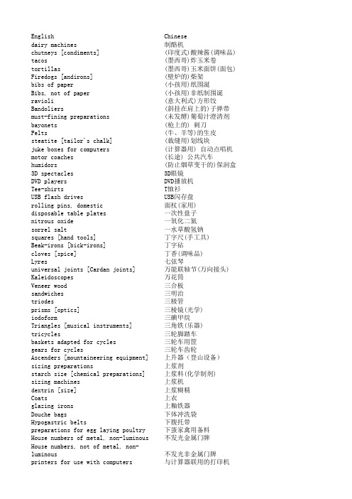
flax meal [fodder]
亚麻粉(饲料)
Linen thread and yarn
pastejewelrycostumejewelry乳糖原料乳胶天然胶乳酒奶饮料二氧化钛颜料五金器具亚麻粉饲料交通信号登信号装置人造增甜剂化学制剂人造宝石服装用珠宝人造宝石服装用珠宝articialresinsseminishedproductsarticialplants人造植物articialfruit人造水果pearlsmadeambroidpressedamberambroidbars人造琥珀条nesteggsarticial人造留窝鸡蛋articialeyes人造眼睛articialstone人造石rayonthreadyarn人造线和纱articialowers人造花wreathsarticialowers人造花制花环articialgarlands人造花环articialshingbait人造钓鱼饵articialjaws人造颚margarine人造黄油axseedhumanconsumption人食用亚麻籽linseedhumanconsumption人食用亚麻籽wheatgermhumanconsumption人食用小麦胚芽groatshumanfood人食用的去壳谷物silkwormchrysalishumanconsumption人食用蚕蛹shmealhumanconsumption人食用鱼粉malthumanconsumption人食用麦芽liveries仆侍人员行会会员等穿的制服beerbasedcocktails以啤酒为主的鸡尾酒fruitbasedsnackfood以水果为主的零食小吃ricebasedsnackfood以米为主的零食小吃nonalcoholichoneybasedbeverages以蜂蜜为主的无酒精饮料cerealbasedsnackfood以谷物为主的零食小吃fuelalcoholicbase以酒精为主的燃料fabricimitationanimalskins仿兽皮的织物tortoiseshellimitation仿制玳瑁壳imitationleather仿皮clothingleather仿皮服装maraboutsclothvodka伏特加酒voltmeters伏特计invoicingmachines会计机umbrellasumbrellacovers伞套umbrellahandles伞柄umbrellasticksumbrellaringsbelts传动带用润滑
阀体材质代号一览表之欧阳文创编

阀体材质代号一览表
F8---304 CF8M---316, CF3---304L, CF3M---316L 这些是常用阀门材料代号,表示铸件!对应的锻钢代号
是:F304、F316、F304L、F316L以下为几种不锈钢阀门材料参数及具体运用:
PFA树脂相对来说是比较新的可熔融加工的氟塑料。
PFA的熔点大约为580F,密度为2.13— 2.16g/cc(克/立方厘米)。
PFA与 PTFE和FEP相似,但在302T以上时,机械性能略优于FEP,且可在高达500F下的温度下使用,它的耐化学品性与PTEF相当。
PFA的产品形式有用于模塑和挤塑的粒状产品,用于旋转模塑和涂料的粉状产品;其半成品有膜、板、棒和管材。
美国市场经销的PFA树脂有DUPOut公司的Teflon牌、Daikin公司的Neoflon牌、Ansimont公司的Hthen牌、HOechst Celanese公司的 Hostafl牌。
PFA的用途与FEP类似。
各种型号铝青铜铜套的特性
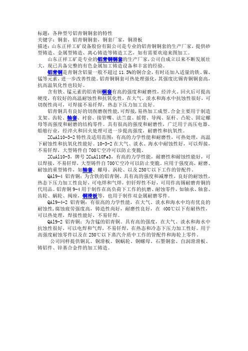
标题:各种型号铝青铜铜套的特性关键字:铜套,铝青铜铜套,铜套厂家,铜滑板描述:山东正祥工矿设备股份有限公司是专业的铝青铜铜套的生产厂家,提供砂型铸造、金属型铸造、离心铸造等铸造工艺,如有需要欢迎来图加工。
山东正祥工矿是专业的铝青铜铜套的生产厂家,公司自成立以来不断发展壮大,现已具备完整的有色金属加工铸造设备和丰富的经验。
铝青铜是青铜含铝量一般不超过11.5%的铜合金,有时还加入适量的铁、镍、锰等元素,进一步改善性能。
铝青铜铜套可热处理强化,其强度比锡青铜铜套高,抗高温氧化性也较好。
含有铁、锰元素的铝青铜铜套有高的强度和耐磨性,经淬火、回火后可提高硬度,有较好的高温耐蚀性和抗氧化性,在大气、淡水和海水中抗蚀性很好,可切削性尚可,可焊接不易纤焊,热态下压力加工良好。
铝青铜具有良好的切削磨削性能,可焊接,易热加工成型。
合金主要用于制造支架、齿轮、轴套、衬套、接管嘴、法兰盘、摇臂、导阀、泵杆、凸轮、固定螺母等高强度和耐磨的结构零件。
具有很高的强度和耐磨性,广泛用于高压电器、船舶行业,经淬火和回火处理可进一步提高强度,耐磨性和抗氧性。
ZCuAl10-3-2特性及适用范围:有高的力学性能和耐磨性,可热处理,高温下耐蚀性和抗氧化性能好。
10-3-2在大气、淡水、海水中耐蚀性好,可以焊接,不易钎焊,大型铸件自700℃空冷可以防止变脆。
ZCuAl10-3,牌号ZCuAl10Fe3,有高的力学性能,耐磨性和耐蚀性能好,可以焊接,不易钎焊,大型铸件自700℃空冷可以防止变脆。
应用于强度高,耐磨、耐蚀的重型铸件,如轴套、螺母、涡轮、以及250℃以下工作的管配件。
QAl9-4 铝青铜;为含铁的铝青铜。
具有高的强度和减摩性,良好的耐蚀性,热态下压力加工性良好,可电焊和气焊,但钎焊性不好,可用作高锡耐磨青铜的代用品。
铝青铜9-4用于制作在高负荷下工作的抗磨、耐蚀零件,如轴承、轴套、齿轮、蜗轮、阀座,铜滑板等,也用于制作双金属耐磨零件。
ADUM1410_1411_1412_cn中文资料

受美国专利5,952,849号、6,873,065号、6,903,578号和7,075,329号保护。 Document Feedback
Rev. J
Information furnished by Analog Devices is believed to be accurate and reliable. However, no responsibility is assumed by Analog Devices for its use, nor for any infringements of patents or other rights of third parties that may result from its use. Speci cations subject to change without notice. No license is granted by implication or otherwise under any patent or patent rights of Analog Devices. Trademarks and registered trademarks are the property of their respective owners.
修订历史
2014年4月—修订版I至修订版J 更改表5 ......................................................................................... 10 2012年3月—修订版H至修订版I 为特性部分的“安全和法规认证”创建超链接 ........................ 1 更改印刷电路板布局部分 ........................................................ 19 2010年11月—修订版G至修订版H 特性部分增加TÜV认证 .............................................................. 1 表5增加TÜV栏 ............................................................................ 10 2007年6月—修订版F至修订版G 全面更新VDE认证 ....................................................................... 1 更改特性和应用部分 ................................................................... 1 更改表1中的直流规格 ................................................................. 3 更改表2中的直流规格 ................................................................. 5 更改表3中的直流规格 ................................................................. 7 更改法规信息部分 ..................................................................... 10 增加表10 ....................................................................................... 12 增加隔离寿命部分 ..................................................................... 21 2007年2月—修订版E至修订版F 增加ADuM1410ARWZ .......................................................... 通篇 引脚名称CTRL统一更新为CTRL2............................................ 1 更改订购指南 .............................................................................. 21 2006年10月—修订版D至修订版E 增加ADuM1411和ADuM1412 ............................................. 通篇 删除ADuM1310....................................................................... 通篇 更改“特性”...................................................................................... 1 更改技术规格部分 ....................................................................... 3 更新外形尺寸 .............................................................................. 20 更改“订购指南”............................................................................20 2006年3月—修订版C至修订版D 增加注释1并更改图2 ................................................................... 1 更改绝对最大额定值 ................................................................. 11 2005年11月—修订版C:初始版065Biblioteka 0-001CTRL2 GND2
410 电力配送产品指南说明书

691062
Kyoritsu digital multimeter / 6mm Dia. clamp meter-AC/DC V, ohm, Hz
KEWMATE2000
Kyoritsu digital multimeter / 10mm Dia. clamp meter-AC/DC V, ohm, Hz
Item no. 2040 2002PA 2002R 2007A 2031 2117R 2127R 2200 2608A 2805 KT200
Test & Measure
1109S 2200
Clamp meters AC/DC
Model 2046R • CAT. IV 600V rating • Current up to 600A AC/DC • Voltage up to 600V AC/DC • Continuity buzzer
• Measurement from 0.01mA to 120.0mA • Dual display with backlight shows both mA
measurement and percentage of 4-20 mA span • Analog output terminal for recorder connection
Description Kyoritsu analogue multimeter with dB & hFE Kyoritsu analogue multimeter with temperature & continuity buzzer.
Item no. 1109S 1110
Clamp meters AC
Model 2200 • Maximum AC current measurement 1000A • Maximum AC voltage measurement 600V • 33 mm diameter conductor size • Ultra slim and light weight
阀体材质代号一览表之欧阳历创编
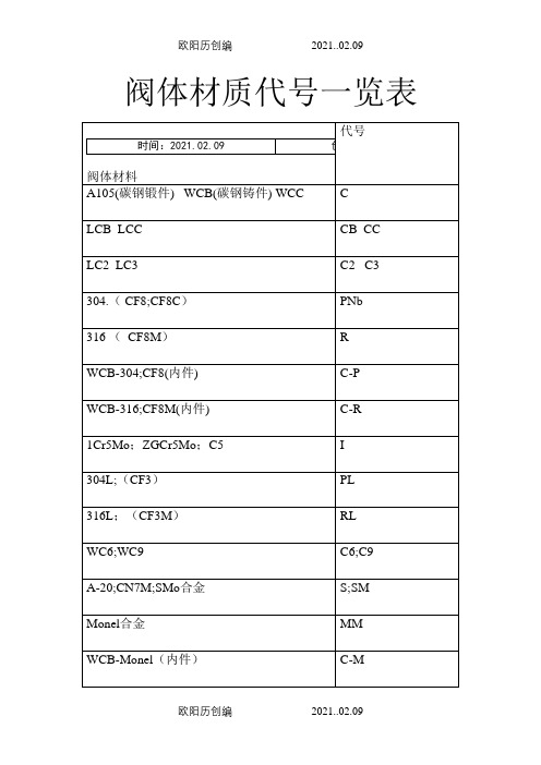
阀体材质代号一览表
F8---304 CF8M---316, CF3---304L, CF3M---316L 这些是常用阀门材料代号,表示铸件!对应的锻钢代号是:F304、F316、F304L、F316L以下为几种不锈钢阀门材料参数及具体运用:
PFA树脂相对来说是比较新的可熔融加工的氟塑料。
PFA的熔点大约为580F,密度为2.13— 2.16g/cc(克/立方厘米)。
PFA与 PTFE和FEP相似,但在302T以上时,机械性能略优于FEP,且可在高达500F下的温度下使用,它的耐化学品性与PTEF相当。
PFA的产品形式有用于模塑和挤塑的粒状产品,用于旋转模塑和涂料的粉状产品;其半成品有膜、板、棒和管材。
美国市场经销的PFA树脂有DUPOut公司的Teflon牌、Daikin公司的Neoflon牌、Ansimont公司的Hthen牌、HOechst Celanese公司的Hostafl牌。
PFA的用途与FEP类似。
6014 Compact Solenoid Valve说明书

Compact Solenoid Valve - PneumaticType 6014 Sub-base ConnectionCircuit functionC 3/2-way valve,when de-energized, outlet Apressure relievedSymbolOperating voltages AC 24, 110, 230 V/50 Hz,DC 12, 24 V/=Voltage tolerance ±10 %Power consumption AC inrush AC hold DC 32 mm-coil 20 VA 13 VA/5 W 5 WDuty cycle 100% continously ratedDuty cycle for multiple 100% continously rated manifolds Cycling rate up to 1200 c.p.m.Rating with cable plug IP 65Electr. connection Delivery standard:Cable plug DIN 43650 A,0-250 V (Other versions see accessories)Pressure range0-10 bar (see specifications)Port connectionSub-base connection OrificeDN 1,5 mm Fluid Compressed air Suitable for techn. vacuum Medium temperature–10 bis +60 °C Max. ambient temperature+55 °C Max. viscosity21 mm 2/s Response timesopeningAC 10-15 ms; DC 15-20 ms closingAC 15-20 ms; DC 10-22 ms Installation as required, but preferablywith solenoid system uprightCompact Solenoid Valve - Pneumatic Sub-base Connection Type 60141Valve body:Polyamide 2Plunger seal:F K M 3O-rings:F K M 4Armature guide tube: 1.43035Plunger: 1.41056Spring: 1.43107Shading ring:Cu (copper)8Stopper: 1.41059Flange:Zn3 gl cC (surface)10Bonnet:Durethan BKV30H 11Coil:PA (Polyamide)12Flat seal:NBR 13Cable plug:PA (Polyamide)14Locknut:9SMnPb28K (surface Zn5glcA)Compact Solenoid Valve - Pneumatic Sub-base Connection Type 6014Type 6014; polyamide body (PA); coil 5W;(with standard-cable plug 0-250 V AC/DC).1)Measured with 6 bar upstream pressure and 1 bar pressure drop across the valve at +20˚C.2) All pressures quoted are gauge pressures with respect to the prevailing atmospheric pressure.Dimensions (in mm)Solenoid coil: 5W power consumption Cable plug DIN 43650,form A (0-250 V AC/DC)delivery standard。
- 1、下载文档前请自行甄别文档内容的完整性,平台不提供额外的编辑、内容补充、找答案等附加服务。
- 2、"仅部分预览"的文档,不可在线预览部分如存在完整性等问题,可反馈申请退款(可完整预览的文档不适用该条件!)。
- 3、如文档侵犯您的权益,请联系客服反馈,我们会尽快为您处理(人工客服工作时间:9:00-18:30)。
M TC1410/TC1410NFeatures•Latch-Up Protected: Will Withstand 500mA Reverse Current•Input Will Withstand Negative Inputs Up to 5V •ESD Protected: 4kV•High Peak Output Current: 0.5A•Wide Input Supply Voltage Operating Range:- 4.5V to 16V•High Capacitive Load Drive Capability:-500pF in 25nsec•Short Delay Time: 30nsec Typ.•Consistent Delay Times With Changes in Supply Voltage•Matched Delay Times•Low Supply Current- With Logic ‘1’ Input: 500µA- With Logic ‘0’ Input: 100µA•Low Output Impedance: 16Ω•Available in Space-Saving 8-pin MSOP Package •Pinout Same as TC1411/TC1412/TC1413Applications•Switch Mode Power Supplies•Line Drivers•Pulse Transformer Drive•Relay Driver General DescriptionThe TC1410/TC1410N are 0.5A CMOS buffers/drivers. They will not latch-up under any conditions within their power and voltage ratings. They are not subject to damage when up to 5V of noise spiking of either polarity occurs on the ground pin. They can accept, without damage or logic upset, up to 500mA of current of either polarity being forced back into their output. All terminals are fully protected against up to 4kV of electrostatic discharge.As MOSFET drivers, the TC1410/TC1410N can easily charge a 500pF gate capacitance in 25nsec with matched rise and fall times, and provide low enough impedance in both the ‘ON’ and ‘OFF’ states to ensure the MOSFET’s intended state will not be affected, even by large transients. The leading and trailing edge propagation delay times are also matched to allow driving short-duration inputs with greater accuracy. Package Type8-Pin MSOP/PDIP/SOIC1234V DD5678OUTGNDV DDINNCGNDOUTTC141NC = No Connection26,7Inverting26,7Non-Inverting12345678TC141NV DDINNCGNDV DDOUTGNDOUTNOTE: Duplicate pins must be connected together for proper operation.0.5A High-Speed MOSFET Drivers2003 Microchip Technology Inc.DS21389C-page 1TC1410/TC1410NDS21389C-page 2 2003 Microchip Technology Inc.Functional Block DiagramEffective Input C = 10pFTC1410NOutputInputGNDV DD300mV4.7VInverting Non-InvertingOutputOutputTC1410TC1410/TC1410N1.0ELECTRICALCHARACTERISTICSAbsolute Maximum Ratings †Supply Voltage.....................................................+20V Input Voltage......................V DD + 0.3V to GND – 5.0V Power Dissipation (T A≤ 70°C) MSOP..........................................................340mW PDIP............................................................730mW SOIC............................................................470mW Storage Temperature Range..............-65°C to +150°C Maximum Junction Temperature......................+150°C † Stresses above those listed under "Absolute Maximum Ratings" may cause permanent damage to the device. These are stress ratings only and functional operation of the device at these or any other conditions above those indicated in the operation sections of the specifications is not implied. Exposure to Absolute Maximum Rating conditions for extended periods may affect device reliability.PIN FUNCTION TABLESymbol DescriptionV DD Supply input, 4.5V to 16V INPUT Control inputNC No connectionGND GroundGND GroundOUTPUT CMOS push-pull output,common to pin 7 OUTPUT CMOS push-pull output,common to pin 6V DD Supply input, 4.5V to 16VDC ELECTRICAL CHARACTERISTICSElectrical Specifications: Unless otherwise noted, over operating temperature range with 4.5V ≤ V DD ≤ 16V. Typical values are measured at T A = +25°C, V DD= 16V.Parameters Sym Min Typ Max Units ConditionsInputLogic ‘1’, High Input Voltage V IH 2.0——VLogic ‘0’, Low Input Voltage V IL——0.8VInput Current I IN-1—1µA0V ≤ V IN ≤ V DD, T A = +25°C-10—10-40°C ≤ T A ≤ +85°COutputHigh Output Voltage V OH V DD – 0.025——V DC TestLow Output Voltage V OL——0.025V DC TestOutput Resistance R O—1622ΩV DD = 16V, I O = 10mA, T A = +25°C—20280°C ≤ T A ≤ +70°C—2028-40°C ≤ T A ≤ +85°CPeak Output Current I PK—0.5—A V DD = 16VLatch-Up Protection Withstand Reverse Current I REV—0.5—A Duty cycle ≤ 2%, t ≤ 300µsec,V DD = 16VSwitching Time (Note1)Rise Time t R—2535nsec T A = +25°C—27400°C ≤ T A ≤ +70°C—2940-40°C ≤ T A ≤ +85°C, Figure4-1 Fall Time t F—2535nsec T A = +25°C—27400°C ≤ T A ≤ +70°C—2940-40°C ≤ T A ≤ +85°C, Figure4-1 Delay Time t D1—3040nsec T A = +25°C—33450°C ≤ T A ≤ +70°C—3545-40°C ≤ T A ≤ +85°C, Figure4-1 Note1:Switching times ensured by design.2003 Microchip Technology Inc.DS21389C-page 3TC1410/TC1410NDC ELECTRICAL CHARACTERISTICS (CONTINUED)Electrical Specifications: Unless otherwise noted, over operating temperature range with 4.5V ≤ V DD ≤ 16V. Typical values are measured at T A = +25°C, V DD= 16V.Parameters Sym Min Typ Max Units ConditionsDelay Time t D2—3040nsec T A = +25°C—33450°C ≤ T A ≤ +70°C—3545-40°C ≤ T A ≤ +85°C, Figure4-1 Power SupplyPower Supply Current I S—0.5 1.0mA V IN = 3V, V DD = 16V—0.10.15V IN = 0VNote1:Switching times ensured by design.TEMPERATURE CHARACTERISTICSElectrical Specifications: Unless otherwise noted, all parameters apply with 4.5V ≤ V DD≤ 16V.Parameters Sym Min Typ Max Units Conditions Temperature RangesSpecified Temperature Range (C)T A0—+70ºCSpecified Temperature Range (E)T A-40—+85ºCMaximum Junction Temperature T J——+150ºCStorage Temperature Range T A-65—+150ºCPackage Thermal ResistancesThermal Resistance, 8L-MSOPθJA—206—ºC/WThermal Resistance, 8L-PDIPθJA—125—ºC/WThermal Resistance, 8L-SOICθJA—155—ºC/WDS21389C-page 4 2003 Microchip Technology Inc.TC1410/TC1410N 2.0TYPICAL PERFORMANCE CURVESNote: Unless otherwise indicated, over operating temperature range with 4.5V ≤ V DD ≤ 16V.FIGURE 2-1:Quiescent Supply Current vs. Supply Voltage.FIGURE 2-2:Input Threshold vs. Supply Voltage.FIGURE 2-3:High-State Output Resistance vs. Supply Voltage.FIGURE 2-4:Quiescent Supply Current vs. Temperature.FIGURE 2-5:Input Threshold vs. Temperature.FIGURE 2-6:Low-State Output Resistance vs. Supply Voltage.Note:The graphs and tables provided following this note are a statistical summary based on a limited number of samples and are provided for informational purposes only. The performance characteristics listed herein are not tested or guaranteed. In some graphs or tables, the data presented may be outside the specified operating range (e.g., outside specified power supply range) and therefore outside the warranted range.2003 Microchip Technology Inc.DS21389C-page 5TC1410/TC1410NDS21389C-page 6 2003 Microchip Technology Inc.Note: Unless otherwise indicated, over operating temperature range with 4.5V ≤ V DD ≤ 16V.FIGURE 2-7:Rise Time vs. SupplyVoltage.FIGURE 2-8:Propagation Delay vs.Supply Voltage.FIGURE 2-9:Rise and Fall Times vs.Capacitive Load.FIGURE 2-10:Fall Time vs. SupplyVoltage.FIGURE 2-11:Propagation Delay vs.Supply Voltage.FIGURE 2-12:Propagation Delays vs.Capacitive Load.TC1410/TC1410N3.0PIN DESCRIPTIONSThe descriptions of the pins are listed in Table3-1. TABLE 3-1:PIN FUNCTION TABLE3.1Supply Input (V DD)The V DD input is the bias supply for the MOSFET driver and is rated for 4.5V to 16V with respect to the ground pin. The V DD input should be bypassed to ground with a local ceramic capacitor. The value of the capacitor should be chosen based on the capacitive load that is being driven. A value of 1.0µF is suggested.3.2Control Input (INPUT)The MOSFET driver input is a high-impedance, TTL/CMOS-compatible input. The input also has 300mV of hysteresis between the high and low thresholds that prevents output glitching even when the rise and fall time of the input signal is very slow.3.3CMOS Push-Pull Output(OUTPUT)The MOSFET driver output is a low-impedance, CMOS, push-pull style output, capable of driving a capacitive load with 0.5A peak currents.3.4GroundThe ground pins are the return path for the bias current and for the high peak currents that discharge the load capacitor. The ground pins should be tied into a ground plane or have very short traces to the bias supply source return.Pin No.Symbol Description1V DD Supply input, 4.5V to 16V2INPUT Control input3NC No connection4GND Ground5GND Ground6OUTPUT CMOS push-pull output, commonto pin 77OUTPUT CMOS push-pull output, commonto pin 68V DD Supply input, 4.5V to 16V2003 Microchip Technology Inc.DS21389C-page 7TC1410/TC1410NDS21389C-page 8 2003 Microchip Technology Inc.4.0APPLICATIONS INFORMATIONFIGURE 4-1:Switching Time Test Circuit.C L = 500pF 0.1µF1.0µFInverting DriverNon-Inverting DriverInputV DD = 16VInputOutput t D1t Ft Rt D2Input: 100kHz,square wave,t RISE = t FALL ≤ 10nsecOutputInputOutputt D1t Ft Rt D2+5V 10%90%10%90%10%90%V DD 0V90%10%10%10%90%+5V V DD 0V0V0V 90%4, 526, 71, 8TC1410TC1410NTC1410NTC14102003 Microchip Technology Inc.DS21389C-page 9TC1410/TC1410N5.0PACKAGING INFORMATION5.1Package Marking Information8-Lead PDIP (300 mil)Example:Legend: XX (X)Customer specific information*YY Year code (last 2 digits of calendar year)WW Week code (week of January 1 is week ‘01’)NNN Alphanumeric traceability codeNote :In the event the full Microchip part number cannot be marked on one line, it will be carried over to the next line thus limiting the number of available characters for customer specific information.*Standard marking consists of Microchip part number, year code, week code, traceability code (facility code, mask rev#, and assembly code). For marking beyond this, certain price adders apply. Pleasecheck with your Microchip Sales Office.8-Lead SOIC (150 mil)8-Lead MSOP Example:XXXXXXX YWWNNN 1410NE 346057TC1410/TC1410NDS21389C-page 10 2003 Microchip Technology Inc.8-Lead Plastic Dual In-line (PA) – 300 mil (PDIP)B1BA1ALA2pαEeBβcE1nD12UnitsINCHES *MILLIMETERSDimension LimitsMINNOMMAXMIN NOMMAXNumber of Pins n 88Pitchp.100 2.54Top to Seating PlaneA .140.155.170 3.56 3.94 4.32Molded Package Thickness A2.115.130.145 2.92 3.30 3.68Base to Seating PlaneA1.0150.38Shoulder to Shoulder Width E .300.313.3257.627.948.26Molded Package Width E1.240.250.260 6.10 6.35 6.60Overall LengthD .360.373.3859.149.469.78Tip to Seating Plane L .125.130.135 3.18 3.30 3.43Lead Thickness c .008.012.0150.200.290.38Upper Lead Width B1.045.058.070 1.14 1.46 1.78Lower Lead Width B .014.018.0220.360.460.56Overall Row Spacing §eB .310.370.4307.879.4010.92Mold Draft Angle Top α5101551015Mold Draft Angle Bottom β5101551015* Controlling Parameter Notes:Dimensions D and E1 do not include mold flash or protrusions. Mold flash or protrusions shall not exceed JEDEC Equivalent: MS-001Drawing No. C04-018.010” (0.254mm) per side.§ Significant Characteristic2003 Microchip Technology Inc.DS21389C-page 11TC1410/TC1410N8-Lead Plastic Small Outline (OA) –Narrow, 150 mil (SOIC)Foot Angleφ048048151201512βMold Draft Angle Bottom 1512015120αMold Draft Angle Top 0.510.420.33.020.017.013B Lead Width0.250.230.20.010.009.008c Lead Thickness 0.760.620.48.030.025.019L Foot Length 0.510.380.25.020.015.010h Chamfer Distance 5.004.904.80.197.193.189D Overall Length 3.993.913.71.157.154.146E1Molded Package Width 6.206.025.79.244.237.228E Overall Width0.250.180.10.010.007.004A1Standoff § 1.551.421.32.061.056.052A2Molded Package Thickness 1.751.551.35.069.061.053A Overall Height1.27.050pPitch88n Number of Pins MAXNOMMINMAX NOMMINDimension LimitsMILLIMETERSINCHES*Units21D npBE E1hLβc45°φA2αAA1* Controlling Parameter Notes:Dimensions D and E1 do not include mold flash or protrusions. Mold flash or protrusions shall not exceed .010” (0.254mm) per side.JEDEC Equivalent: MS-012Drawing No. C04-057§ Significant CharacteristicTC1410/TC1410N8-Lead Plastic Micro Small Outline Package (UA) (MSOP)DS21389C-page 12 2003 Microchip Technology Inc.2003 Microchip Technology Inc.DS21389C-page 13TC1410/TC1410NPRODUCT IDENTIFICATION SYSTEMTo order or obtain information, e.g., on pricing or delivery, refer to the factory or the listed sales office .Sales and SupportDevice:TC1410: 0.5A Single MOSFET Driver, InvertingTC1410N: 0.5A Single MOSFET Driver, Non-InvertingT emperature Range:C = 0°C to +70°C E=-40°C to +85°CPackage:OA =Plastic SOIC, (150 mil Body), 8-lead OA713=Plastic SOIC, (150 mil Body), 8-lead(Tape and Reel)UA =Plastic Micro Small Outline (MSOP), 8-lead *UA713=Plastic Micro Small Outline (MSOP), 8-lead *(Tape and Reel)PA =Plastic DIP (300 mil Body), 8-lead * MSOP package is only available in E-T emp.PART NO.X /XX PackageTemperature RangeDeviceExamples:a)TC1410COA:0.5A Single MOSFET driver, SOIC package, 0°C to +70°C.b)TC1410CPA:0.5A Single MOSFETdriver, PDIP package,0°C to +70°C.c)TC1410EUA713:Tape and Reel,0.5A Single MOSFET driver, MSOP package, -40°C to +85°C.a)TC1410NCPA:0.5A Single MOSFETdriver, PDIP package, 0°C to +70°C.b)TC1410NEPA:0.5A Single MOSFET driver, PDIP package, -40°C to +85°C.c)TC1410NEUA:0.5A Single MOSFET driver, MSOP package,-40°C to +85°C.Data SheetsProducts supported by a preliminary Data Sheet may have an errata sheet describing minor operational differences andrecommended workarounds. To determine if an errata sheet exists for a particular device, please contact one of the following:1.Your local Microchip sales office2.The Microchip Corporate Literature Center U.S. FAX: (480) 792-72773.The Microchip Worldwide Site ()Please specify which device, revision of silicon and Data Sheet (include Literature #) you are using.New Customer Notification SystemRegister on our web site (/cn) to receive the most current information on our products.TC1410/TC1410NNOTES:DS21389C-page 14 2003 Microchip Technology Inc.2003 Microchip Technology Inc.DS21389C-page 15Information contained in this publication regarding device applications and the like is intended through suggestion only and may be superseded by updates. It is your responsibility to ensure that your application meets with your specifications.No representation or warranty is given and no liability is assumed by Microchip T echnology Incorporated with respect to the accuracy or use of such information, or infringement of patents or other intellectual property rights arising from such use or otherwise. Use of Microchip’s products as critical com-ponents in life support systems is not authorized except with express written approval by Microchip. No licenses are con-veyed, implicitly or otherwise, under any intellectual property rights.TrademarksThe Microchip name and logo, the Microchip logo, Accuron,dsPIC, K EE L OQ , MPLAB, PIC, PICmicro, PICSTART,PRO MATE and PowerSmart are registered trademarks of Microchip Technology Incorporated in the U.S.A. and other countries.AmpLab, FilterLab, micro ID , MXDEV , MXLAB, PICMASTER,SEEVAL and The Embedded Control Solutions Company are registered trademarks of Microchip Technology Incorporated in the U.S.A.Application Maestro, dsPICDEM, , ECAN,ECONOMONITOR, FanSense, FlexROM, fuzzyLAB,In-Circuit Serial Programming, ICSP , ICEPIC, microPort,Migratable Memory, MPASM, MPLIB, MPLINK, MPSIM,PICkit, PICDEM, , PowerCal, PowerInfo,PowerMate, PowerTool, rfLAB, rfPIC, Select Mode,SmartSensor, SmartShunt, SmartT el and Total Endurance are trademarks of Microchip Technology Incorporated in the U.S.A. and other countries.Serialized Quick Turn Programming (SQTP) is a service mark of Microchip Technology Incorporated in the U.S.A.All other trademarks mentioned herein are property of their respective companies.© 2003, Microchip T echnology Incorporated, Printed in the U.S.A., All Rights Reserved.Printed on recycled paper.Note the following details of the code protection feature on Microchip devices:•Microchip products meet the specification contained in their particular Microchip Data Sheet.•Microchip believes that its family of products is one of the most secure families of its kind on the market today, when used in the intended manner and under normal conditions.•There are dishonest and possibly illegal methods used to breach the code protection feature. All of these methods, to ourknowledge, require using the Microchip products in a manner outside the operating specifications contained in Microchip's Data Sheets. Most likely, the person doing so is engaged in theft of intellectual property.•Microchip is willing to work with the customer who is concerned about the integrity of their code.•Neither Microchip nor any other semiconductor manufacturer can guarantee the security of their code. Code protection does not mean that we are guaranteeing the product as “unbreakable.”Code protection is constantly evolving. We at Microchip are committed to continuously improving the code protection features of our products. Attempts to break microchip’s code protection feature may be a violation of the Digital Millennium Copyright Act. If such acts allow unauthorized access to your software or other copyrighted work, you may have a right to sue for relief under that Act.Microchip received QS-9000 quality system certification for its worldwide headquarters, design and wafer fabrication facilities in Chandler and Tempe, Arizona in July 1999 and Mountain View, California in March 2002. The Company’s quality system processes and procedures are QS-9000 compliant for itsPICmicro ® 8-bit MCUs, K EE L OQ ® code hopping devices, Serial EEPROMs, microperipherals, non-volatile memory and analog products. In addition, Microchip’s quality system for the design and manufacture of development systems is ISO 9001 certified.MAMERICASCorporate Office2355 West Chandler Blvd.Chandler, AZ 85224-6199Tel: 480-792-7200Fax: 480-792-7277Technical Support: 480-792-7627Web Address: Atlanta3780 Mansell Road, Suite 130 Alpharetta, GA 30022Tel: 770-640-0034Fax: 770-640-0307Boston2 Lan Drive, Suite 120Westford, MA 01886Tel: 978-692-3848Fax: 978-692-3821Chicago333 Pierce Road, Suite 180Itasca, IL 60143Tel: 630-285-0071Fax: 630-285-0075Dallas4570 Westgrove Drive, Suite 160 Addison, TX 75001Tel: 972-818-7423Fax: 972-818-2924DetroitTri-Atria Office Building32255 Northwestern Highway, Suite 190 Farmington Hills, MI 48334Tel: 248-538-2250Fax: 248-538-2260Kokomo2767 S. Albright RoadKokomo, IN 46902Tel: 765-864-8360Fax: 765-864-8387Los Angeles18201 Von Karman, Suite 1090 Irvine, CA 92612Tel: 949-263-1888Fax: 949-263-1338Phoenix2355 West Chandler Blvd.Chandler, AZ 85224-6199Tel: 480-792-7966Fax: 480-792-4338San Jose2107 North First Street, Suite 590San Jose, CA 95131Tel: 408-436-7950Fax: 408-436-7955Toronto6285 Northam Drive, Suite 108 Mississauga, Ontario L4V 1X5, Canada Tel: 905-673-0699Fax: 905-673-6509ASIA/PACIFICAustraliaSuite 22, 41 Rawson StreetEpping 2121, NSWAustraliaTel: 61-2-9868-6733Fax: 61-2-9868-6755China - BeijingUnit 915Bei Hai Wan Tai Bldg.No. 6 Chaoyangmen BeidajieBeijing, 100027, No. ChinaTel: 86-10-85282100Fax: 86-10-85282104China - ChengduRm. 2401-2402, 24th Floor,Ming Xing Financial TowerNo. 88 TIDU StreetChengdu 610016, ChinaTel: 86-28-86766200Fax: 86-28-86766599China - FuzhouUnit 28F, World Trade PlazaNo. 71 Wusi RoadFuzhou 350001, ChinaTel: 86-591-7503506Fax: 86-591-7503521China - Hong Kong SARUnit 901-6, T ower 2, Metroplaza223 Hing Fong RoadKwai Fong, N.T., Hong KongTel: 852-2401-1200Fax: 852-2401-3431China - ShanghaiRoom 701, Bldg. BFar East International PlazaNo. 317 Xian Xia RoadShanghai, 200051Tel: 86-21-6275-5700Fax: 86-21-6275-5060China - ShenzhenRm. 1812, 18/F, Building A, United PlazaNo. 5022 Binhe Road, Futian DistrictShenzhen 518033, ChinaTel: 86-755-82901380Fax: 86-755-8295-1393China - ShundeRoom 401, Hongjian BuildingNo. 2 Fengxiangnan Road, Ronggui T ownShunde City, Guangdong 528303, ChinaTel: 86-765-8395507 Fax: 86-765-8395571China - QingdaoRm. B505A, Fullhope Plaza,No. 12 Hong Kong Central Rd.Qingdao 266071, ChinaTel: 86-532-5027355 Fax: 86-532-5027205IndiaDivyasree Chambers1 Floor, Wing A (A3/A4)No. 11, O’Shaugnessey RoadBangalore, 560 025, IndiaTel: 91-80-2290061 Fax: 91-80-2290062JapanBenex S-1 6F3-18-20, ShinyokohamaKohoku-Ku, Yokohama-shiKanagawa, 222-0033, JapanTel: 81-45-471- 6166 Fax: 81-45-471-6122Korea168-1, Youngbo Bldg. 3 FloorSamsung-Dong, Kangnam-KuSeoul, Korea 135-882Tel: 82-2-554-7200 Fax: 82-2-558-5932 or82-2-558-5934Singapore200 Middle Road#07-02 Prime CentreSingapore, 188980Tel: 65-6334-8870 Fax: 65-6334-8850TaiwanKaohsiung Branch30F - 1 No. 8Min Chuan 2nd RoadKaohsiung 806, T aiwanTel: 886-7-536-4818Fax: 886-7-536-4803TaiwanTaiwan Branch11F-3, No. 207Tung Hua North RoadTaipei, 105, TaiwanTel: 886-2-2717-7175 Fax: 886-2-2545-0139EUROPEAustriaDurisolstrasse 2A-4600 WelsAustriaTel: 43-7242-2244-399Fax: 43-7242-2244-393DenmarkRegus Business CentreLautrup hoj 1-3Ballerup DK-2750 DenmarkTel: 45-4420-9895 Fax: 45-4420-9910FranceParc d’Activite du Moulin de Massy43 Rue du Saule TrapuBatiment A - ler Etage91300 Massy, FranceTel: 33-1-69-53-63-20Fax: 33-1-69-30-90-79GermanySteinheilstrasse 10D-85737 Ismaning, GermanyTel: 49-89-627-144-0Fax: 49-89-627-144-44ItalyVia Quasimodo, 1220025 Legnano (MI)Milan, ItalyTel: 39-0331-742611Fax: 39-0331-466781NetherlandsP. A. De Biesbosch 14NL-5152 SC Drunen, NetherlandsTel: 31-416-690399Fax: 31-416-690340United Kingdom505 Eskdale RoadWinnersh TriangleWokinghamBerkshire, England RG41 5TUTel: 44-118-921-5869Fax: 44-118-921-582007/28/03W ORLDWIDE S ALES AND S ERVICEDS21389C-page 16 2003 Microchip Technology Inc.。
