TLV2262IDRG4中文资料
TLV2262IDG4中文资料
Copyright 2001, Texas Instruments Incorporated
POST OFFICE BOX 655303
• DALLAS, TEXAS 75265
1
元器件交易网
SLOS186B − FEBRUARY 1997 − REVISED MARCH 2001
元器件交易网
ąą
TLV226x, TLV226xA Advanced LinCMOS RAILĆTOĆRAIL OPERATIONAL AMPLIFIERS
SLOS186B − FEBRUARY 1997 − REVISED MARCH 2001
D D D D D D
Output Swing Includes Both Supply Rails Low Noise . . . 12 nV/√Hz Typ at f = 1 kHz Low Input Bias Current . . . 1 pA Typ Fully Specified for Both Single-Supply and Split-Supply Operation Low Power . . . 500 µA Max Common-Mode Input Voltage Range Includes Negative Rail
ÁÁ ÁÁ
0.5
The TLV2262/4 also makes great upgrades to the TLV2332/4 in standard designs. They offer increased output dynamic range, lower noise voltage and lower input offset voltage. This enhanced feature set allows them to be used in a wider range of applications. For applications that require higher output drive and wider input voltage range, see the TLV2432 and TLV2442 devices. If your design requires single amplifiers, please see the TLV2211/21/31 family. These devices are single rail-to-rail operational amplifiers in the SOT-23 package. Their small size and low power consumption, make them ideal for high density, battery-powered equipment.
AD2262 简介 数据手册说明书

深圳市英锐芯电子科技有限公司53万组编码芯片AD2262AD2262简介数据手册版本V1.0电话:*************82568883邮箱:**********************传真:*************网址:公司地址:深圳市福田区滨河大道联合广场A座1308深圳市英锐芯电子科技有限公司53万组编码芯片AD2262一、AD2262原理与简介AD2262是一种CMOS 工艺制造的低功耗低价位通用编码芯片,AD2262最多有12位(A0~A11)三态地址端管脚(悬空、接高电平、低电平),任意组合可提供531441组地址编码。
AD2262最多有6位(D0~D5)数据端管脚,设定的地址和数据通过17脚串行输出,主要应用在无线遥控发射电路。
二、功能特点◆CMOS 工艺制造、功耗低◆外部元器件少;◆外接RC 震荡电阻,编码宽度改变灵活;◆工作电压宽:3V-13V ;◆数据最多6位,可组合多组按键输入;◆地址码高达53W 组;三、应用领域◆车辆防盗系统;◆家庭防盗系统;◆遥控玩具;◆其他的电器遥控;四、AD2262脚位图:AD2262管脚说明电话:*************82568883邮箱:**********************传真:*************网址:公司地址:深圳市福田区滨河大道联合广场A 座1308深圳市英锐芯电子科技有限公司53万组编码芯片AD2262五、电气参数表:六、AD2262编码格式:注意:1bit =32a电话:*************82568883邮箱:**********************传真:*************网址:公司地址:深圳市福田区滨河大道联合广场A 座1308深圳市英锐芯电子科技有限公司53万组编码芯片AD2262AD2262典型应用:芯片封装尺寸:如没有特别提示,所有尺寸标注均为:英尺(毫米)本手册内容改动及版本更新将不再另行通知,深圳市英锐芯电子科技有限公司保留所有权利电话:*************82568883邮箱:**********************传真:*************网址:公司地址:深圳市福田区滨河大道联合广场A座1308。
PT2262~2272
目录:0.引言: (1)1.无线通讯 (1)1.1无线通讯的现状与发展 (1)1.2无线通讯的应用 (1)1.3无线通讯的展望 (2)2.电路设计 (2)2.1无线收发的原理 (2)2.2 SC2262/SC2272编解码电路 (3)2.2.1 SC2262芯片介绍 (3)2.2.2 SC2272芯片介绍 (3)2.2.3 74LS244 (4)2.2.4 74LS273芯片介绍 (4)2.3 总体电路 (5)3.软件设计 (5)4.电路及应用说明 (9)5.结语 (9)6.致谢 (9)参考文献 (9)基于SC2262/SC2272的简易无线收发系统[摘要] 介绍了无线通讯的发展和应用,以及给我们生活带来的影响。
简单介绍了SC2262/SC2272的基本原理,并设计了一种基于SC2262/SC2272的简易无线收发系统。
此系统结构简单、搭建容易、抗干扰能力强,经过适当改造可以应用于遥控装置、无线抢答器等实用性很强的设计,是一种很实用的基础设计。
[关键词]无线传输、SC2262、SC22720.引言:在我们现在的生活环境中,到处都离不开无线通讯的身影。
近几年来,无线通讯迅猛发展,已经成为了一种日趋成熟的技术。
无线通讯为我们提供了许多的便利,使我们的沟通更加便捷迅速,也使我们的生活更加的简便安全。
无线通讯包含着许多的方面,本文介绍了利用SC2262/SC2272芯片制作的简易无线收发系统。
该系统可以完成无线收发,经过适当改造后可以应用于遥控报警系统、遥控装置、遥控玩具、无线抢答器等实用性很强的设计。
1.无线通讯1.1无线通讯的现状与发展无线电是指在自由空间(包括空气和真空)传播的电磁波,是其中的一个有限频带,上限频在300GHz(吉赫兹),下限频率较不统一, 在各种射频规范中, 常见的有三种:3KHz~300GHz(ITU-国际电信联盟规定), 9KHz~300GHz, 10KHz~300GHz[1]。
TLV2402中文资料
元器件交易网IMPORTANT NOTICETexas Instruments and its subsidiaries (TI) reserve the right to make changes to their products or to discontinueany product or service without notice, and advise customers to obtain the latest version of relevant informationto verify, before placing orders, that information being relied on is current and complete. All products are soldsubject to the terms and conditions of sale supplied at the time of order acknowledgement, including thosepertaining to warranty, patent infringement, and limitation of liability.TI warrants performance of its semiconductor products to the specifications applicable at the time of sale inaccordance with TI’s standard warranty. Testing and other quality control techniques are utilized to the extentTI deems necessary to support this warranty. Specific testing of all parameters of each device is not necessarilyperformed, except those mandated by government requirements.CERTAIN APPLICATIONS USING SEMICONDUCTOR PRODUCTS MAY INVOLVE POTENTIAL RISKS OFDEATH, PERSONAL INJURY, OR SEVERE PROPERTY OR ENVIRONMENTAL DAMAGE (“CRITICALAPPLICATIONS”). TI SEMICONDUCTOR PRODUCTS ARE NOT DESIGNED, AUTHORIZED, ORWARRANTED TO BE SUITABLE FOR USE IN LIFE-SUPPORT DEVICES OR SYSTEMS OR OTHERCRITICAL APPLICATIONS. INCLUSION OF TI PRODUCTS IN SUCH APPLICATIONS IS UNDERSTOOD TOBE FULLY AT THE CUSTOMER’S RISK.In order to minimize risks associated with the customer’s applications, adequate design and operatingsafeguards must be provided by the customer to minimize inherent or procedural hazards.TI assumes no liability for applications assistance or customer product design. TI does not warrant or representthat any license, either express or implied, is granted under any patent right, copyright, mask work right, or otherintellectual property right of TI covering or relating to any combination, machine, or process in which suchsemiconductor products or services might be or are used. TI’s publication of information regarding any thirdparty’s products or services does not constitute TI’s approval, warranty or endorsement thereof.Copyright © 2000, Texas Instruments Incorporated。
TLV2775IDG4资料

元器件交易网
TLV277x, TLV277xA FAMILY OF 2.7ĆV HIGHĆSLEWĆRATE RAILĆTOĆRAIL OUTPUT OPERATIONAL AMPLIFIERS WITH SHUTDOWN
SLOS209G − JANUARY 1998 − REVISED FEBRUARY 2004
TLV2770 and TLV2771 AVAILABLE OPTIONS TA 0°C to 70°C VIOmax AT 25°C (mV) 2.5 2.5 −40°C to 125°C 1.6 PACKAGED DEVICES SMALL OUTLINE (D) TLV2770CD TLV2771CD TLV2770ID TLV2771ID TLV2770AID TLV2771AID SOT-23 (DBV) — TLV2771CDBV — TLV2771IDBV — — MSOP (DGK) TLV2770CDGK† — TLV2770IDGK† — — — PLASTIC DIP (P) TLV2770CP — TLV2770IP — TLV2770AIP —
1
元器件交易网
SLOS209G − JANUARY 1998 − REVISED FEBRUARY 2004
TLV277x, TLV277xA FAMILY OF 2.7ĆV HIGHĆSLEWĆRATE RAILĆTOĆRAIL OUTPUT OPERATIONAL AMPLIFIERS WITH SHUTDOWN
TLV2262ID中文资料
1
元器件交易网
TLV226x, TLV226xA Advanced LinCMOS™ RAIL-TO-RAIL OPERATIONAL AMPLIFIERS
TLV2262 AVAILABLE OPTIONS PACKAGED DEVICES TA VIOmax AT 25°C 2.5 mV 950 µV µ 2.5 mV 950 µV µ 2.5 mV 950 µV 2.5 mV SMALL OUTLINE (D) TLV2262CD TLV2262AID TLV2262ID TLV2262AQD TLV2262QD — — CHIP CARRIER (FK) — — — — — TLV2262AMFK TLV2262MFK CERAMIC DIP (JG) — — — — — TLV2262AMJG TLV2262MJG PLASTIC DIP (P) TLV2262CP TLV2262AIP TLV2262IP — — — — TSSOP (PW) TLV2262CPWLE TLV2262AIPWLE — — — — — CERAMIC FLATPACK (U) — — — — — TLV2262AMU TLV2262MU
元器件交易网
TLV226x, TLV226xA Advanced LinCMOS™ RAIL-TO-RAIL OPERATIONAL AMPLIFIERS
SLOS186A – FEBRUARY 1997 – REVISED JULY 1999
D D D D D D
Output Swing Includes Both Supply Rails Low Noise . . . 12 nV/√Hz Typ at f = 1 kHz Low Input Bias Current . . . 1 pA Typ Fully Specified for Both Single-Supply and Split-Supply Operation Low Power . . . 500 µA Max Common-Mode Input Voltage Range Includes Negative Rail
TLV2460中文文档

增益带宽积(MHz)
电源电压(V) 温度(℃)
大信号波动(V)
小信号波动(V)
反向大信号波动(V)
反向小信号波动(V)
参数的测量方法
TLV246X家族系列运算放大器的应用
1.驱动容性负载
输出失调电压是输入失调电压和输入偏置电流乘以相应的增益的和,下面的原理图和公式可以用来计算输出失调电压。
2.一般的连接电路
温馨提示:买家在使用该款芯片的时候最好要去当地的经销商去实地查看一下元器件的焊接掩膜封装,放置由于厂家生产的时候改动了一些实际的封装而导致该封装与实际样板上面的封装不匹配。
该图片是向消费者展示该贴片封装的芯片的实物图从不同角度观察的视图
左上角:该芯片从左下角到左上角逆时针旋转依次对应该芯片的1——8脚,芯片体的长度在工业生产中对应4.30mm到4.50mm之间,在样板上芯片整体的长度为6.20mm到6.60mm之间,芯片引脚所占的空间为0.19mm到0.30mm之间,引脚与引脚之间的间距为0.65mm,故顾客在购买该款芯片的时候有较大的考虑余地也给实际制版带来了一定的方便
TLV2460/3/5为节省电池寿命有一个关断功能的便携式应用,电源电流降低至0.3μA/通道被禁用,放大器和输出置于高阻抗模式。为了使放大器,关闭终端可以悬空或拉到高。当关闭终端悬空,护理应采取措施,确保在关闭终端,寄生漏电流不不经意的地方进入关断的运算放大器。关闭终端的门槛总是引用到VDD / 2。因此,经营分割电源电压的设备(如:± 2.5 V)时,关闭终端需要拉至VDD(不接地)禁用运算放大器。
tm2262
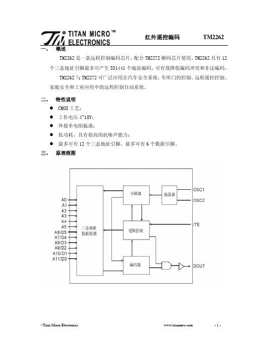
一、 概述TM2262是一款远程控制编码芯片,配合TM2272解码芯片使用。
TM2262具有12个三态地址引脚最多可产生531441个地址编码,可有效降低编码冲突和非法编码。
TM2262与TM2272可广泛应用在汽车安全系统、车库门的控制、远程遥控控制、家庭安全和工业应用中的远程控制自动系统。
二、 特性说明z CMOS工艺;z工作电压4~18V;z外接单电阻振荡;z低功耗,具有很高的抗噪声能力;z最多可有12个三态地址引脚,最多可有6个数据引脚。
三、 原理框图四、管脚定义引脚号引脚名输入/ 输出 描述18引脚 20引脚 A0~A5输入地址编码引脚0~5。
这6个引脚都是三态引脚,对应编码波形中的0~5位,每个引脚可被设置为“0”、“1”或“f”(悬空)三种状态。
1~61~6A6/D5~A11/D0 输入可作为地址编码引脚的6~11位或作为数据引脚的5~0位。
这6个引脚都是三态引脚,对应编码波形中的6~11位。
当作为地址引脚时每个引脚可被设置为“0”、“1”或“f”(悬空)三种状态;当作为数据引脚时只能设置为“0”或“1”。
7~8 10~13 7~8 12~15/TE 输入 发送使能端,低电平有效。
当/TE 为低电平时,编码信号从DOUT 端口发送出去。
14 16 OSC1 输出 15 17 OSC2 输入 电阻连接这两端,电阻值决定了振荡的基础频率 16 18 DOUT 输出 数据输出口。
当没有输出时,保持低电平。
1719 VCC - 正电平供电端 18 20 VSS -负电平供电端 99五、功能描述TM2262编码芯片将A0~A5和A6/D5~A11/D0信号编译成指定的波形,当/TE为“0”时,编码信号从DOUT端口输出。
这个波形被使用于RF模式,通过RF解调器来接受和波形恢复。
TM2272可对这波形进行解码,同时对通讯口进行设置。
因此,这二款芯片配合使用可以完成编码和解码功能。
1、射频工作模式位码位码是编码波形中最为基本的组成单元,被划分为数据/地址位和同步位。
TLV2624IDR资料
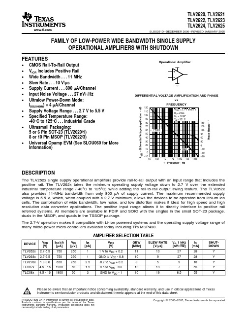
FEATURESOperational Amplifier+−−10102030405060708090100110120f − Frequency − Hz150120906030−30−60−90PhaseMargin−°DIFFERENTIAL VOLTAGE AMPLIFICATION AND PHASEvsFREQUENCY−DifferentialVoltageAmplification−dBAVD180 DESCRIPTIONTLV2620,TLV2621TLV2622,TLV2623TLV2624,TLV2625SLOS251D–DECEMBER2000–REVISED JANUARY2005 FAMILY OF LOW-POWER WIDE BANDWIDTH SINGLE SUPPLYOPERATIONAL AMPLIFIERS WITH SHUTDOWN•CMOS Rail-To-Rail Output•V ICR Includes Positive Rail•Wide Bandwidth...11MHz•Slew Rate...10V/µs•Supply Current...800µA/Channel•Input Noise Voltage...27nV/√Hz•Ultralow Power-Down Mode:I DD(SHDN)=4µA/Channel•Supply Voltage Range...2.7V to5.5V•Specified Temperature Range:-40°C to125°C...Industrial Grade•Ultrasmall Packaging:5or6Pin SOT-23(TLV2620/1)8or10Pin MSOP(TLV2622/3)•Universal Opamp EVM(See SLOU060for MoreInformation)The TLV262x single supply operational amplifiers provide rail-to-rail output with an input range that includes the positive rail.The TLV262x takes the minimum operating supply voltage down to 2.7V over the extended industrial temperature range(-40°C to125°C)while adding the rail-to-rail output swing feature.The TLV262x also provides11-MHz bandwidth from only800µA of supply current.The maximum recommended supply voltage is5.5V,which,when coupled with a2.7-V minimum,allows the devices to be operated from lithium ion cells.The combination of wide bandwidth,low noise,and low distortion makes it ideal for high speed and high resolution data converter applications.The positive input range allows it to directly interface to positive rail referred systems.All members are available in PDIP and SOIC with the singles in the small SOT-23package, duals in the MSOP,and quads in the TSSOP package.The2.7-V operation makes it compatible with Li-Ion powered systems and the operating supply voltage range of many micro-power micro-controllers available today including TI's MSP430.AMPLIFIER SELECTION TABLEV DD I DD/ch V IO I IB V ICR GBW SLEW RATE V n,1kHz I O SHUT-DEVICE[V][µA][µV][pA][V][MHz][V/µs][nV/√Hz][mA]DOWN TLV262x 2.7-5.575025011V to V DD+0.211102728YTLV263x 2.7-5.57502501GND to V DD-0.81092728YTLV278x 1.8-3.6650250 2.5-0.2to V DD+0.285910YTLC07x 4.5-16190060 1.50.5to V DD-0.81019755YTLC08x 4.5-161900603GND to V DD-110198.555YPlease be aware that an important notice concerning availability,standard warranty,and use in critical applications of TexasInstruments semiconductor products and disclaimers thereto appears at the end of this data sheet.PRODUCTION DATA information is current as of publication date.Copyright©2000–2005,Texas Instruments Incorporated Products conform to specifications per the terms of the TexasInstruments standard warranty.Production processing does notnecessarily include testing of all parameters.元器件交易网 TLV2620,TLV2621TLV2622,TLV2623TLV2624,TLV2625SLOS251D–DECEMBER2000–REVISED JANUARY2005This integrated circuit can be damaged by ESD.Texas Instruments recommends that all integratedcircuits be handled with appropriate precautions.Failure to observe proper handling and installationprocedures can cause damage.ESD damage can range from subtle performance degradation to complete device failure.Precisionintegrated circuits may be more susceptible to damage because very small parametric changes couldcause the device not to meet its published specifications.TLV2620AND TLV2621AVAILABLE OPTIONS(1)PACKAGED DEVICESV IO max ATT A SOT-23SMALL OUTLINE25°C PLASTIC DIP(P)(D)(2)(DBV)(3)SYMBOLTLV2620ID TLV2620IDBV VBAI TLV2620IP -40°C to125°C3500µVTLV2621ID TLV2621IDBV VBBI TLV2621IP(1)For the most current package and ordering information,see the Package Option Addendum at the end of this document,or see the TIwebsite at .(2)This package is available taped and reeled.To order this packaging option,add an R suffix to the part number(e.g.,TLV2620IDR).(3)The SOT23package devices are only available taped and reeled.The R Suffix denotes quantities(3,000pieces per reel).For smallerquantities(250pieces per mini-reel),add a T suffix to the part number(e.g.TLV2620IDBVT).TLV2622AND TLV2623AVAILABLE OPTIONS(1)PACKAGED DEVICESV IO max AT SMALL MSOP PLASTIC T A PLASTIC25°C OUTLINE(2)DIPDIP(N)(DGK)(2)SYMBOL(DGS)(2)SYMBOL(D)(P)TLV2622ID TLV2622IDGK xxTIAKM———TLV2622IP -40°C to125°C3500µVTLV2623ID——TLV2623IDGS xxTIALC TLV2623IN—(1)For the most current package and ordering information,see the Package Option Addendum at the end of this document,or see the TIwebsite at .(2)This package is available taped and reeled.To order this packaging option,add an R suffix to the part number(e.g.,TLV2622IDR).TLV2624AND TLV2625AVAILABLE OPTIONS(1)PACKAGED DEVICESV IO maxT A SMALL OUTLINE PLASTIC DIP TSSOPAT25°C(D)(2)(N)(PW)TLV2624ID TLV2624IN TLV2624IPW-40°C to125°C3500µVTLV2625ID TLV2625IN TLV2625IPW(1)For the most current package and ordering information,see the Package Option Addendum at theend of this document,or see the TI website at .(2)This package is available taped and reeled.To order this packaging option,add an R suffix to thepart number(e.g.,TLV2624IDR).2元器件交易网TLV262X PACKAGE PINOUTS (1)(TOP VIEW)OUT GND IN+V DDIN−TLV2621DBV PACKAGE V DD 2OUT 2IN−2IN+2SHDN(TOP VIEW)OUT GND IN+V DD IN−TLV2620DBV PACKAGE SHDN TLV2623DGS PACKAGE (TOP VIEW)NC − No internal connectionTLV2620D OR P PACKAGE(TOP VIEW)NC V DD OUT NC TLV2621D OR P PACKAGE(TOP VIEW)1234 5671413121110981OUT 1IN−1IN+GND NC 1SHDNNCV DD 2OUT 2IN−2IN+NC 2SHDN NC (TOP VIEW)TLV2623D OR N PACKAGE1234 5671413121110981OUT 1IN−1IN+V DD 2IN+2IN−2OUT4OUT 4IN−4IN+GND 3IN+3IN−3OUT(TOP VIEW)TLV2624D, N, OR PW PACKAGE4OUT 4IN−4IN+GND 3IN+3IN−3OUT 3/4SHDN(TOP VIEW)TLV2625D, N, OR PW PACKAGEV DD 2OUT 2IN−2IN+TLV2622D, DGK, OR P PACKAGE(TOP VIEW)3/4SHDN Pin (9) controls amplifiers 3 and 4.Printed or Molded DotBevel EdgesPin 1Molded ”U” ShapePin 1StripePin 1Pin 1TLV2620,TLV2621TLV2622,TLV2623TLV2624,TLV2625SLOS251D–DECEMBER 2000–REVISED JANUARY 2005(1)SOT-23may or may not be indicated.TYPICAL PIN 1INDICATORSNOTE:If there is not a Pin 1indicator,turn device to enable reading the symbol from left to right.Pin 1is at the lower left corner of the device.3元器件交易网ABSOLUTE MAXIMUM RATINGSDISSIPATION RATING TABLERECOMMENDED OPERATING CONDITIONSTLV2620,TLV2621TLV2622,TLV2623TLV2624,TLV2625SLOS251D–DECEMBER 2000–REVISED JANUARY 2005over operating free-air temperature range (unless otherwise noted)(1)V DD Supply voltage(2)6V V ID Differential input voltage ±V DDV I Input voltage range (2)+1to V DD +0.2VI I Input current (any input)±10mA I O Output current±40mAContinuous total power dissipationSee Dissipation Rating TableT A Operating free-air temperature range:I-suffix -40°C to 125°CT J Maximum junction temperature 150°C T stg Storage temperature range-65°C to 150°CLead temperature 1,6mm (1/16inch)from case for 10seconds 260°C(1)Stresses beyond those listed under absolute maximum ratings may cause permanent damage to the device.These are stress ratings only,and functional operation of the device at these or any other conditions beyond those indicated under recommended operating conditions is not implied.Exposure to absolute-maximum-rated conditions for extended periods may affect device reliability.(2)All voltage values,except differential voltages,are with respect to GND.θJCθJAT A ≤25°C T A =125°C PACKAGE (°C/W)(°C/W)POWER RATINGPOWER RATINGD (8)38.3176710mW 142mW D (14)26.9122.31022mW 204.4mW D (16)25.7114.71090mW 218mW DBV (5)55324.1385mW 77.1mW DBV (6)55294.3425mW 85mW DGK (8)54.2259.9481mW 96.1mW DGS (10)54.1259.7485mW 97mW N (14,16)32781600mW 320.5mW P (8)411041200mW 240.4mW PW (14)29.3173.6720mW 144mW PW (16)28.7161.4774mW154.9mWMINMAX UNIT Single supply 2.7 5.5V DD Supply voltageV Split supply±1.35±2.75V ICR Common-mode input voltage range 1V DD +0.2V T AOperating free-air temperature I-suffix -40125°C V IL 0.4Shutdown on/off voltage level (1)VV IH2(1)Relative to GND.4元器件交易网ELECTRICAL CHARACTERISTICSTLV2620,TLV2621TLV2622,TLV2623TLV2624,TLV2625 SLOS251D–DECEMBER2000–REVISED JANUARY2005at specified free-air temperature,VDD=2.7V,5V(unless otherwise noted)PARAMETER TEST CONDITIONS T A(1)MIN TYP MAX UNITDC PERFORMANCE25°C2503500 V IO Input offset voltageµVV IC=V DD/2,V O=V DD/2,Full range4500R S=50ΩTemperature coefficient ofαVIO25°C3µV/°C input offset voltage25°C7798V DD=2.7VFull range63V IC=1to V DD,CMRR Common-mode rejection ratio dBR S=50Ω25°C7899V DD=5VFull range7525°C90100V DD=2.7V,R L=2kΩ,V O(PP)=1.7V Full range82Large-signal differential voltageA VD dBamplification25°C95100V DD=5V,R L=2kΩ,V O(PP)=4V Full range90INPUT CHARACTERISTICS25°C250I IO Input offset currentFull Range100V IC=V DD/2,V O=V DD/2,pAR S=50Ω25°C250I IB Input bias currentFull Range200r i(d)Differential input resistance25°C100GΩCommon-mode inputC i(c)f=1kHz25°C8pFcapacitanceOUTPUT CHARACTERISTICS25°C 2.6 2.67V DD=2.7VFull range 2.55V IC=V DD/2,I OH=-1mA25°C 4.95 4.98V DD=5VFull range 4.9V OH High-level output voltage V25°C 2.3 2.43V DD=2.7VFull range 2.2V IC=V DD/2,I OH=-10mA25°C 4.7 4.8V DD=5VFull range 4.625°C0.030.1V DD=2.7VFull range0.15V IC=V DD/2,I OL=1mA25°C0.0250.05V DD=5VFull range0.1 V OL Low-level output voltage V25°C0.260.4V DD=2.7VFull range0.45V IC=V DD/2,I OL=10mA25°C0.20.25V DD=5VFull range0.35Sourcing14V DD=2.7V,V O=0.5V from rail Sinking19I O Output current25°C mASourcing28V DD=5V,V O=0.5V from rail Sinking28V DD=2.7V50SourcingV DD=5V95I OS Short-circuit output current25°C mAV DD=2.7V50SinkingV DD=5V95(1)Full range is-40°C to125°C for the I-suffix.5元器件交易网TLV2620,TLV2621TLV2622,TLV2623TLV2624,TLV2625SLOS251D–DECEMBER 2000–REVISED JANUARY 2005ELECTRICAL CHARACTERISTICS (continued)at specified free-air temperature,V DD =2.7V,5V (unless otherwise noted)PARAMETERTEST CONDITIONST A (1)MINTYPMAXUNITPOWER SUPPLY 25°C 8001000I DDSupply current (per channel)V O =V DD /2,SHDN =V DDµAFull range 130025°C8098V DD =2.7V to 3.3V,V IC =V DD /2Full range 75Supply voltage rejection ratio PSRRNo loaddB(∆V DD /∆V IO )25°C 7590V DD =2.7V to 5V,V IC =V DD /2Full range 70DYNAMIC PERFORMANCE UGBWUnity gain bandwidthR L =2k Ω,C L =10pF25°C 11MHz25°C 3.5 4.5V DD =2.7V,V O(PP)=1.7V Full range 2.7SR+Positive slew rate at unity gainR L =2k Ω,C L =50pFV/µs 25°C 5.47V DD =5V,V O(PP)=3.5V Full range 3.425°C 2.75V DD =2.7V,V O(PP)=1.7V Full range 2.3SR-Negative slew rate at unity gain R L =2k Ω,C L =50pFV/µs25°C 4.56V DD =5V,V O(PP)=3.5V Full range 3.2φmPhase margin 63°R L =2k Ω,C L =10pF25°CGain margin8dBNOISE/DISTORTION PERFORMANCE A V =10.002%Total harmonic distortion plus V O(PP)=V DD /2,THD +NA V =100.019%noiseR L =2k Ω,f =10kHz A V =1000.095%25°Cf =1kHz 53V n Equivalent input noise voltage nV/√Hz f =10kHz 27I nEquivalent input noise currentf =1kHz0.9fA/√Hz SHUTDOWN CHARACTERISTICS Supply current,per channel in25°C411I DD(SHDN)shutdown mode (TLV2620,SHDN =0.4VµA Full range13TLV2623,TLV2625)V DD =2.7V 4.5t (on)Amplifier turnon time (2)R L =2k Ωµs V DD =5V25°C 1.5t (off)Amplifier turnoff time (2)R L =2k Ω200ns(2)Disable time and enable time are defined as the interval between application of the logic signal to SHDN and the point at which the supply current has reached half its final value.6元器件交易网TYPICAL CHARACTERISTICSTABLE OF GRAPHSf − Frequency − HzC M R R − C o m m o n -M o d e R e j e c t i o n R a t i o − d B 101k 1M10k 100k100−100−500501001502002503003504004505000.00.30.60.9 1.2 1.5 1.8 2.1 2.4 2.7I O V I n p u t O f f s e t V o l t a g e −−VµV ICR − Common-Mode Input Voltage − V−100−50501001502002503003504004505000.00.5 1.0 1.5 2.0 2.5 3.0 3.5 4.0 4.5 5.0I O V I n p u t O f f s e t V o l t a g e −−VµV ICR − Common-Mode Input Voltage − VTLV2620,TLV2621TLV2622,TLV2623TLV2624,TLV2625SLOS251D–DECEMBER 2000–REVISED JANUARY 2005FIGUREV IO Input offset voltagevs Common-mode input voltage 1,2CMRR Common-mode rejection ratio vs Frequency3V OH High-level output voltage vs High-level output current 4,6V OL Low-level output voltage vs Low-level output current 5,7I DD Supply current vs Supply voltage 8I DD Supply currentvs Free-air temperature 9PSRR Power supply rejection ratiovs Frequency 10A VDDifferential voltage amplification &phase vs Frequency11Gain-bandwidth productvs Free-air temperature 12vs Supply voltage 13SR Slew rate vs Free-air temperature 14,15φm Phase marginvs Load capacitance 16V nEquivalent input noise voltagevs Frequency17Voltage-follower large-signal pulse response 18Voltage-follower small-signal pulse response 19Crosstalkvs Frequency20I DD(SHDN)Shutdown supply current vs Free-air temperature 21I DD(SHDN)Shutdown supply currentvs Supply voltage 22I DD(SHDN)Shutdown supply current/output voltagevs Time23INPUT OFFSET VOLTAGEINPUT OFFSET VOLTAGECOMMON-MODE REJECTION RATIOvsvsvsCOMMON-MODE INPUT VOLTAGECOMMON-MODE INPUT VOLTAGEFREQUENCYFigure 1.Figure 2.Figure 3.7元器件交易网I OL − Low-Level Output Current − mAO L V − L o w -L e v e l O u t p u t V o l t a g e − V51015202530354045V O H − H i g h -L e v e l O u t p u t V o l t a g e − VI OH − High-Level Output Current − mA0102030405060708090100V O H − H i g h -L e v e l O u t p u t V o l t a g e − VI OH − High-Level Output Current − mAI OL − Low-Level Output Current − mAO L V − L o w -L e v e l O u t p u t V o l t a g e −V1002003004005006007008009001000−40−25−105203550658095110125T A − Free-Air Temperature − °CD D I S u p p l y C u r r e n t − −A /c hµDD D D I S u p p l y C u r r e n t − −A /c hµ−100102030405060708090100110120 f − Frequency − HzP h a s e M a r g i n − °− D i f f e r e n t i a l V o l t a g e A m p l i f i c a t i o n − d BA V D 0102030405060708090100 f − Frequency − Hz101k 10M10k 100k 100− P o w e r S u p p l y R e j e c t i o n R a t i o − d BP S R R 1M123456789101112−40−25−105203550658095110125T A − Free-Air Temperature − °CG a i n -B a n d w i d t h P r o d u c t − M H zTLV2620,TLV2621TLV2622,TLV2623TLV2624,TLV2625SLOS251D–DECEMBER 2000–REVISED JANUARY 2005HIGH-LEVEL OUTPUT VOLTAGELOW-LEVEL OUTPUT VOLTAGEHIGH-LEVEL OUTPUT VOLTAGEvsvsvsHIGH-LEVEL OUTPUT CURRENTLOW-LEVEL OUTPUT CURRENTHIGH-LEVEL OUTPUT CURRENTFigure 4.Figure 5.Figure 6.LOW-LEVEL OUTPUT VOLTAGESUPPLY CURRENTSUPPLY CURRENTvsvsvsLOW-LEVEL OUTPUT CURRENTSUPPLY VOLTAGEFREE-AIR TEMPERATUREFigure 7.Figure 8.Figure 9.DIFFERENTIAL VOLTAGE POWER SUPPLY REJECTION RATIOAMPLIFICATION AND PHASEGAIN-BANDWIDTH PRODUCTvsvsvsFREQUENCYFREQUENCYFREE-AIR TEMPERATUREFigure 10.Figure 11.Figure 12.8元器件交易网123456789101112131415−40−25−105203550658095110125T A − Free-Air Temperature − °CS R − S l e w R a t e − V /µs123456789101112131415−40−25−105203550658095110125T A − Free-Air Temperature − °CS R − S l e w R a t e − V /µs1234567891011122.73.03.33.63.94.24.54.85.15.45.76.0V DD − Supply Voltage − VS R − S l e w R a t e − V /µs0510152025303540455055606570C L − Load Capacitance − pF10300100φm − P h a s e M a r g i n − °050100150200250300350400450500 f − Frequency − Hz101k 100k10k100n V /H z− E q u i v a l e n t I n p u t N o i s e V o l t a g e −V n− C o m m o n -M o d e I n p u t V o l t a g e − VV I Ct − Time − µs− C o m m o n -M o d e I n p u t V o l t a g e − VV I C TLV2620,TLV2621TLV2622,TLV2623TLV2624,TLV2625SLOS251D–DECEMBER 2000–REVISED JANUARY 2005SLEW RATESLEW RATESLEW RATEvsvsvsSUPPLY VOLTAGEFREE-AIR TEMPERATUREFREE-AIR TEMPERATUREFigure 13.Figure 14.Figure 15.EQUIVALENT INPUT NOISEPHASE MARGINVOLTAGEvsvsLOAD CAPACITANCEFREQUENCYFigure 16.Figure 17.VOLTAGE-FOLLOWER LARGE-SIGNALVOLTAGE-FOLLOWER SMALL-SIGNALPULSE RESPONSEPULSE RESPONSEFigure 18.Figure 19.9元器件交易网−140−120−100−80−60−40−200 f − Frequency − Hz101k 100k10k100C r o s s t a l k − d B0.00.51.01.52.02.53.03.54.0−40−25−105203550658095110125T A − Free-Air Temperature − °CD D (S D )I S h u t d o w n S u p p l y C u r r e n t −−A /c hµDDD D (S D )I S h u t d o w n S u p p l y C u r r e n t −−A /c hµS D − S h u t d o w n P u l s e − Vt − Time − µs− O u t p u t V o l t a g e − m VV O D D (S D )I S h u t d o w n S u p p l y C u r r e n t −−A µTLV2620,TLV2621TLV2622,TLV2623TLV2624,TLV2625SLOS251D–DECEMBER 2000–REVISED JANUARY 2005CROSSTALKSHUTDOWN SUPPLY CURRENTSHUTDOWN SUPPLY CURRENTvsvsvsFREQUENCYFREE-AIR TEMPERATURESUPPLY VOLTAGEFigure 20.Figure 21.Figure 22.SHUTDOWN SUPPLY CURRENT/OUTPUT VOLTAGEvs Figure 23.10元器件交易网PACKAGING INFORMATIONOrderable Device Status(1)PackageType PackageDrawingPins PackageQtyEco Plan(2)Lead/Ball Finish MSL Peak Temp(3)TLV2620ID ACTIVE SOIC D875Pb-Free(RoHS)CU NIPDAU Level-2-260C-1YEAR/Level-1-220C-UNLIMTLV2620IDBVR ACTIVE SOT-23DBV63000Green(RoHS&no Sb/Br)CU NIPDAU Level-1-260C-UNLIMTLV2620IDBVT ACTIVE SOT-23DBV6250Green(RoHS&no Sb/Br)CU NIPDAU Level-1-260C-UNLIMTLV2620IDR ACTIVE SOIC D82500Pb-Free(RoHS)CU NIPDAU Level-2-260C-1YEAR/Level-1-220C-UNLIMTLV2620IP ACTIVE PDIP P850Pb-Free(RoHS)CU NIPDAU Level-NC-NC-NCTLV2621ID ACTIVE SOIC D875Pb-Free(RoHS)CU NIPDAU Level-2-260C-1YEAR/Level-1-220C-UNLIMTLV2621IDBVR ACTIVE SOT-23DBV53000Green(RoHS&no Sb/Br)CU NIPDAU Level-1-260C-UNLIMTLV2621IDBVT ACTIVE SOT-23DBV5250Green(RoHS&no Sb/Br)CU NIPDAU Level-1-260C-UNLIMTLV2621IDR ACTIVE SOIC D82500Pb-Free(RoHS)CU NIPDAU Level-2-260C-1YEAR/Level-1-220C-UNLIMTLV2621IP ACTIVE PDIP P850Pb-Free(RoHS)CU NIPDAU Level-NC-NC-NCTLV2622ID ACTIVE SOIC D875Pb-Free(RoHS)CU NIPDAU Level-2-260C-1YEAR/Level-1-220C-UNLIMTLV2622IDGK ACTIVE MSOP DGK880None CU NIPDAU Level-1-220C-UNLIM TLV2622IDGKR ACTIVE MSOP DGK82500None CU NIPDAU Level-1-220C-UNLIMTLV2622IDR ACTIVE SOIC D82500Pb-Free(RoHS)CU NIPDAU Level-2-260C-1YEAR/Level-1-220C-UNLIMTLV2622IP ACTIVE PDIP P850Pb-Free(RoHS)CU NIPDAU Level-NC-NC-NCTLV2623ID ACTIVE SOIC D1450Pb-Free(RoHS)CU NIPD Level-2-260C-1YEAR/Level-1-220C-UNLIMTLV2623IDGS ACTIVE MSOP DGS1080None CU SNPB Level-1-220C-UNLIM TLV2623IDGSR ACTIVE MSOP DGS102500None CU SNPB Level-1-220C-UNLIMTLV2623IDR ACTIVE SOIC D142500Pb-Free(RoHS)CU NIPD Level-2-260C-1YEAR/Level-1-220C-UNLIMTLV2623IN ACTIVE PDIP N1425Pb-Free(RoHS)CU NIPDAU Level-NC-NC-NCTLV2624ID ACTIVE SOIC D1450Pb-Free(RoHS)CU NIPDAU Level-2-260C-1YEAR/Level-1-220C-UNLIMTLV2624IDR ACTIVE SOIC D142500Pb-Free(RoHS)CU NIPDAU Level-2-260C-1YEAR/Level-1-220C-UNLIMTLV2624IN ACTIVE PDIP N1425Pb-Free(RoHS)CU NIPD Level-NC-NC-NC TLV2624IPW ACTIVE TSSOP PW1490None CU NIPDAU Level-1-220C-UNLIM TLV2624IPWR ACTIVE TSSOP PW142000None CU NIPDAU Level-1-220C-UNLIM TLV2624IPWRG4ACTIVE TSSOP PW142000Green(RoHS&no Sb/Br)CU NIPDAU Level-1-260C-UNLIMTLV2625ID ACTIVE SOIC D1640Pb-Free(RoHS)CU NIPDAU Level-2-260C-1YEAR/Level-1-220C-UNLIMOrderable Device Status(1)PackageType PackageDrawingPins PackageQtyEco Plan(2)Lead/Ball Finish MSL Peak Temp(3)TLV2625IDR ACTIVE SOIC D162500Pb-Free(RoHS)CU NIPDAU Level-2-260C-1YEAR/Level-1-220C-UNLIMTLV2625IN ACTIVE PDIP N1625Pb-Free(RoHS)CU NIPDAU Level-NC-NC-NC TLV2625IPW ACTIVE TSSOP PW1690None CU NIPDAU Level-1-220C-UNLIM TLV2625IPWR ACTIVE TSSOP PW162000None CU NIPDAU Level-1-220C-UNLIM (1)The marketing status values are defined as follows:ACTIVE:Product device recommended for new designs.LIFEBUY:TI has announced that the device will be discontinued,and a lifetime-buy period is in effect.NRND:Not recommended for new designs.Device is in production to support existing customers,but TI does not recommend using this part in a new design.PREVIEW:Device has been announced but is not in production.Samples may or may not be available.OBSOLETE:TI has discontinued the production of the device.(2)Eco Plan-May not be currently available-please check /productcontent for the latest availability information and additional product content details.None:Not yet available Lead(Pb-Free).Pb-Free(RoHS):TI's terms"Lead-Free"or"Pb-Free"mean semiconductor products that are compatible with the current RoHS requirements for all6substances,including the requirement that lead not exceed0.1%by weight in homogeneous materials.Where designed to be soldered at high temperatures,TI Pb-Free products are suitable for use in specified lead-free processes.Green(RoHS&no Sb/Br):TI defines"Green"to mean"Pb-Free"and in addition,uses package materials that do not contain halogens, including bromine(Br)or antimony(Sb)above0.1%of total product weight.(3)MSL,Peak Temp.--The Moisture Sensitivity Level rating according to the JEDECindustry standard classifications,and peak solder temperature.Important Information and Disclaimer:The information provided on this page represents TI's knowledge and belief as of the date that it is provided.TI bases its knowledge and belief on information provided by third parties,and makes no representation or warranty as to the accuracy of such information.Efforts are underway to better integrate information from third parties.TI has taken and continues to take reasonable steps to provide representative and accurate information but may not have conducted destructive testing or chemical analysis on incoming materials and chemicals.TI and TI suppliers consider certain information to be proprietary,and thus CAS numbers and other limited information may not be available for release.In no event shall TI's liability arising out of such information exceed the total purchase price of the TI part(s)at issue in this document sold by TI to Customer on an annual basis.元器件交易网元器件交易网IMPORTANT NOTICETexas Instruments Incorporated and its subsidiaries (TI) reserve the right to make corrections, modifications,enhancements, improvements, and other changes to its products and services at any time and to discontinueany product or service without notice. Customers should obtain the latest relevant information before placingorders and should verify that such information is current and complete. All products are sold subject to TI’s termsand conditions of sale supplied at the time of order acknowledgment.TI warrants performance of its hardware products to the specifications applicable at the time of sale inaccordance with TI’s standard warranty. T esting and other quality control techniques are used to the extent TIdeems necessary to support this warranty. Except where mandated by government requirements, testing of allparameters of each product is not necessarily performed.TI assumes no liability for applications assistance or customer product design. Customers are responsible fortheir products and applications using TI components. T o minimize the risks associated with customer productsand applications, customers should provide adequate design and operating safeguards.TI does not warrant or represent that any license, either express or implied, is granted under any TI patent right,copyright, mask work right, or other TI intellectual property right relating to any combination, machine, or processin which TI products or services are used. Information published by TI regarding third-party products or servicesdoes not constitute a license from TI to use such products or services or a warranty or endorsement thereof.Use of such information may require a license from a third party under the patents or other intellectual propertyof the third party, or a license from TI under the patents or other intellectual property of TI.Reproduction of information in TI data books or data sheets is permissible only if reproduction is withoutalteration and is accompanied by all associated warranties, conditions, limitations, and notices. Reproductionof this information with alteration is an unfair and deceptive business practice. TI is not responsible or liable forsuch altered documentation.Resale of TI products or services with statements different from or beyond the parameters stated by TI for thatproduct or service voids all express and any implied warranties for the associated TI product or service andis an unfair and deceptive business practice. TI is not responsible or liable for any such statements.Following are URLs where you can obtain information on other Texas Instruments products and applicationsolutions:Products ApplicationsAmplifiers Audio /audioData Converters Automotive /automotiveDSP Broadband /broadbandInterface Digital Control /digitalcontrolLogic Military /militaryPower Mgmt Optical Networking /opticalnetworkMicrocontrollers Security /securityTelephony /telephonyVideo & Imaging /videoWireless /wirelessMailing Address:Texas InstrumentsPost Office Box 655303 Dallas, Texas 75265Copyright 2005, Texas Instruments Incorporated。
TLV1544CD;TLV1544CPW;TLV1544ID;TLV1548IDB;TLV1544CDR;中文规格书,Datasheet资料
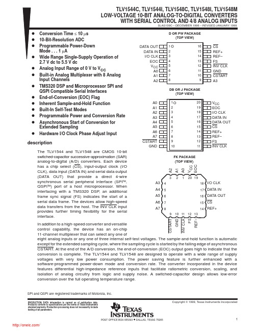
description (continued)
The TLV1544 has four analog input channels while the TLV1548 has eight analog input channels. The TLV1544C and TLV1548C are characterized for operation from 0°C to 70°C. The TLV1544I and TLV1548I are characterized for operation over the full industrial temperature range of –40°C to 85°C. The TLV1548M is characterized for operation over the full military temperature range of –55°C to 125°C.
D D D D D D D D D D D D D
Conversion Time ≤ 10 µs 10-Bit-Resolution ADC Programmable Power-Down Mode . . . 1 µA Wide Range Single-Supply Operation of 2.7 V dc to 5.5 V dc Analog Input Range of 0 V to VCC Built-in Analog Multiplexer with 8 Analog Input Channels TMS320 DSP and Microprocessor SPI and QSPI Compatible Serial Interfaces End-of-Conversion (EOC) Flag Inherent Sample-and-Hold Function Built-In Self-Test Modes Programmable Power and Conversion Rate Asynchronous Start of Conversion for Extended Sampling Hardware I/O Clock Phase Adjust Input
关于2262芯片简介

编码解码芯片PT2262/PT2272芯片原理简介:PT2262/2272是台湾普城公司生产的一种CMOS工艺制造的低功耗低价位通用编解码电路,PT2262/2272最多可有12位(A0-A11)三态地址端管脚(悬空,接高电平,接低电平),任意组合可提供531441地址码,PT2262最多可有6位(D0-D5)数据端管脚,设定的地址码和数据码从17脚串行输出,可用于无线遥控发射电路。
编码芯片PT2262发出的编码信号由:地址码、数据码、同步码组成一个完整的码字,解码芯片PT2272接收到信号后,其地址码经过两次比较核对后,VT脚才输出高电平,与此同时相应的数据脚也输出高电平,如果发送端一直按住按键,编码芯片也会连续发射。
当发射机没有按键按下时,PT2262不接通电源,其17脚为低电平,所以315MHz的高频发射电路不工作,当有按键按下时,PT2262得电工作,其第17脚输出经调制的串行数据信号,当17脚为高电平期间315MHz的高频发射电路起振并发射等幅高频信号,当17脚为低平期间315MHz的高频发射电路停止振荡,所以高频发射电路完全收控于PT2262的17脚输出的数字信号,从而对高频电路完成幅度键控(ASK调制)相当于调制度为100%的调幅。
PT2262/2272特点:CMOS工艺制造,低功耗,外部元器件少,RC 振荡电阻,工作电压范围宽:2.6~15v ,数据最多可达6位,地址码最多可达531441种。
应用范围:车辆防盗系统、家庭防盗系统、遥控玩具、其他电器遥控。
名称管脚说明A0-A111-8、10-13地址管脚,用于进行地址编码,可置为“0”,“1”,“f”(悬空),D0-D57-8、10-13数据输入端,有一个为“1”即有编码发出,内部下拉Vcc18电源正端(+)Vss9电源负端(-)TE14编码启动端,用于多数据的编码发射,低电平有效;OSC116振荡电阻输入端,与OSC2所接电阻决定振荡频率;OSC215振荡电阻振荡器输出端;Dout17编码输出端(正常时为低电平)在具体的应用中,外接振荡电阻可根据需要进行适当的调节,阻值越大振荡频率越慢,编码的宽度越大,发码一帧的时间越长。
BM2262资料

BM2262
单位:μm
Y 坐标 -243.0 -494.0 -494.0 -494.0 -494.0 -494.0 -494.0 -524.1 -320.4 -132.4 58.6 249.6 494.1 494.1 494.1 502.6 438.2 137.5 -15.0
BOOKLY MICRO ELECTRONIC LIMITED CORP.
BOOKLY MICRO ELECTRONIC LIMITED CORP.
元器件交易网
BM2262
管脚说明 管脚号
18 引线封装 20 引线封装
1~6
1~6
7~8 10~13
7~8 12~15
14
16
15
17
16
18
17
19
18
20
9
9
-
10~11
管脚名称 I/O A0~A5 I
A6/D5 ~ I A11/D0
TEN
I
OSC1
O
OSC2
I
DOUT O
VDD -
GND -
NC
-
说明
前六位地址管脚,BM2262 通过检测 这六条三态管脚来确定 0~5 位的编 码数据。每个管脚均可置为“0”、“1” 或“f”(悬空) 6#~11#地址管脚或 5#~0#数据管脚。 BM2262 通过检测这六个管脚来确定 6~11 位的编码波形。当它们作为地 址管脚时,可分别置“0”、“1”或“f”, 当它们作为数据管脚时,只能置为“0” 或“1”。 允许发射信号,低电平有效。应用于 非零数据发射时,此管脚接低电平。 外接一个振荡电阻,以确定 BM2262 的基本振荡频率,注意选择合适的电 阻,使 BM2262 与 BM2272 的振荡频 率相匹配。
TLV1562IDW;TLV1562CPW;TLV1562IPW;TLV1562CPWG4;TLV1562IPWG4;中文规格书,Datasheet资料

PRODUCTION DATA information is current as of publication date. Products conform to specifications per the terms of Texas Instruments standard warranty. Production processing does not necessarily include testing of all parameters.
D D D D D D D D D D D D D D D D
Built-In Internal/System Mid-Scale Error Calibration Built-In Mux With 2 Differential or 4 Single-Ended Input Channels Low Input Capacitance (10 pF Max Fixed, 1 pF Max Switching) DSP/µ P-Compatible Parallel Interface
TLV1562 2.7 V TO 5.5 V, HIGH-SPEED LOW-POWER RECONFIGURABLE ANALOG-TO-DIGITAL CONVERTER WITH 4-INPUT, DUAL S/H, PARALLEL INTERFACE, AND POWER DOWN
SLAS162 – SEPTEMBER 1998
applications
Portable Digital Radios Personal Communication Assistants Cellular Pager Scanner Digitizers Process Controls Motor Control Remote Sensing Automotive Servo Controls Cameras
2272-2262无线模块说明
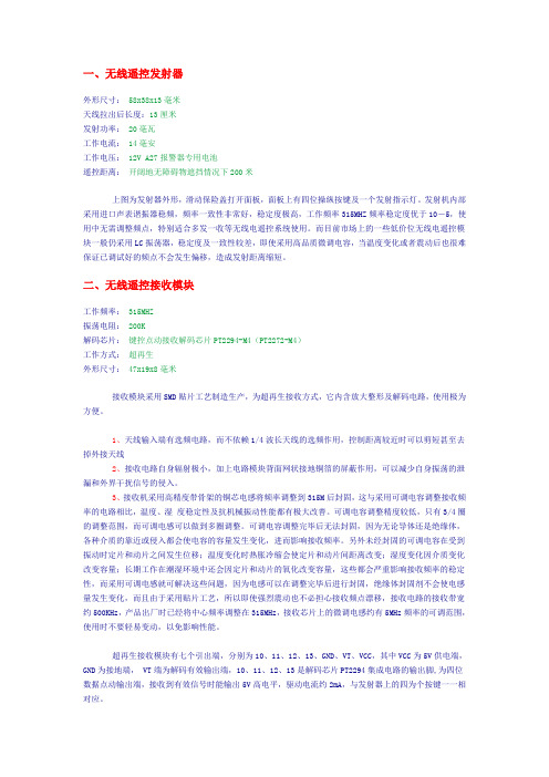
一、无线遥控发射器外形尺寸:58x38x13毫米天线拉出后长度:13厘米发射功率:20毫瓦工作电流:14毫安工作电压:12V A27报警器专用电池遥控距离:开阔地无障碍物遮挡情况下200米上图为发射器外形,滑动保险盖打开面板,面板上有四位操纵按键及一个发射指示灯。
发射机内部采用进口声表谐振器稳频,频率一致性非常好,稳定度极高,工作频率315MHZ频率稳定度优于10-5,使用中无需调整频点,特别适合多发一收等无线电遥控系统使用。
而目前市场上的一些低价位无线电遥控模块一般仍采用LC振荡器,稳定度及一致性较差,即使采用高品质微调电容,当温度变化或者震动后也很难保证已调试好的频点不会发生偏移,造成发射距离缩短。
二、无线遥控接收模块工作频率:315MHZ振荡电阻:200K解码芯片:键控点动接收解码芯片PT2294-M4(PT2272-M4)工作方式:超再生外形尺寸:47x19x8毫米接收模块采用SMD贴片工艺制造生产,为超再生接收方式,它内含放大整形及解码电路,使用极为方便。
1、天线输入端有选频电路,而不依赖1/4波长天线的选频作用,控制距离较近时可以剪短甚至去掉外接天线2、接收电路自身辐射极小,加上电路模块背面网状接地铜箔的屏蔽作用,可以减少自身振荡的泄漏和外界干扰信号的侵入。
3、接收机采用高精度带骨架的铜芯电感将频率调整到315M后封固,这与采用可调电容调整接收频率的电路相比,温度、湿度稳定性及抗机械振动性能都有极大改善。
可调电容调整精度较低,只有3/4圈的调整范围,而可调电感可以做到多圈调整。
可调电容调整完毕后无法封固,因为无论导体还是绝缘体,各种介质的靠近或侵入都会使电容的容量发生变化,进而影响接收频率。
另外未经封固的可调电容在受到振动时定片和动片之间发生位移;温度变化时热胀冷缩会使定片和动片间距离改变;湿度变化因介质变化改变容量;长期工作在潮湿环境中还会因定片和动片的氧化改变容量,这些都会严重影响接收频率的稳定性,而采用可调电感就可解决这些问题,因为电感可以在调整完毕后进行封固,绝缘体封固剂不会使电感量发生变化,而且由于采用贴片工艺,所以即使强烈震动也不必担心接收频点漂移,接收电路的接收带宽约500KHz,产品出厂时已经将中心频率调整在315MHz,接收芯片上的微调电感约有5MHz频率的可调范围,使用时不要轻易变动,以免影响性能。
LMV324IPWRG4中文资料

PACKAGING INFORMATIONOrderableDevice Status (1)Package Type Package Drawing Pins Package Qty Eco Plan (2)Lead/Ball Finish MSL Peak Temp (3)LMV321IDBVR ACTIVE SOT-23DBV 53000Green (RoHS &no Sb/Br)CU NIPDAU Level-1-260C-UNLIM LMV321IDBVT ACTIVE SOT-23DBV 5250Green (RoHS &no Sb/Br)CU NIPDAU Level-1-260C-UNLIM LMV321IDBVTE4ACTIVE SOT-23DBV 5250Green (RoHS &no Sb/Br)CU NIPDAU Level-1-260C-UNLIM LMV321IDCKR ACTIVE SC70DCK 53000Green (RoHS &no Sb/Br)CU NIPDAU Level-1-260C-UNLIM LMV321IDCKRG4ACTIVE SC70DCK 53000Green (RoHS &no Sb/Br)CU NIPDAU Level-1-260C-UNLIM LMV321IDCKT ACTIVE SC70DCK 5250Green (RoHS &no Sb/Br)CU NIPDAU Level-1-260C-UNLIM LMV321IDCKTE4ACTIVE SC70DCK 5250Green (RoHS &no Sb/Br)CU NIPDAU Level-1-260C-UNLIM LMV324ID ACTIVE SOIC D 1450Green (RoHS &no Sb/Br)CU NIPDAU Level-1-260C-UNLIM LMV324IDR ACTIVE SOIC D 142500Green (RoHS &no Sb/Br)CU NIPDAU Level-1-260C-UNLIM LMV324IPWR ACTIVE TSSOP PW 142000Green (RoHS &no Sb/Br)CU NIPDAU Level-1-260C-UNLIM LMV324IPWRG4ACTIVE TSSOP PW 142000Green (RoHS &no Sb/Br)CU NIPDAU Level-1-260C-UNLIM LMV324QD ACTIVE SOIC D 1450Green (RoHS &no Sb/Br)CU NIPDAU Level-1-260C-UNLIM LMV324QDR ACTIVE SOIC D 142500Green (RoHS &no Sb/Br)CU NIPDAU Level-1-260C-UNLIM LMV324QPW ACTIVE TSSOP PW 1490Green (RoHS &no Sb/Br)CU NIPDAU Level-1-260C-UNLIM LMV324QPWE4ACTIVE TSSOP PW 1490Green (RoHS &no Sb/Br)CU NIPDAU Level-1-260C-UNLIM LMV324QPWR ACTIVE TSSOP PW 142000Green (RoHS &no Sb/Br)CU NIPDAU Level-1-260C-UNLIM LMV324SID ACTIVE SOIC D 1640Green (RoHS &no Sb/Br)CU NIPDAU Level-1-260C-UNLIM LMV324SIDE4ACTIVE SOIC D 1640Green (RoHS &no Sb/Br)CU NIPDAU Level-1-260C-UNLIM LMV324SIDR ACTIVE SOIC D 162500Green (RoHS &no Sb/Br)CU NIPDAU Level-1-260C-UNLIM LMV324SIDRE4ACTIVE SOIC D 162500Green (RoHS &no Sb/Br)CU NIPDAU Level-1-260C-UNLIM LMV324SIPWR ACTIVE TSSOP PW 162000Green (RoHS &no Sb/Br)CU NIPDAU Level-1-260C-UNLIM LMV324SIPWRE4ACTIVE TSSOP PW 162000Green (RoHS &no Sb/Br)CU NIPDAU Level-1-260C-UNLIM LMV358ID ACTIVE SOIC D 875Green (RoHS &no Sb/Br)CU NIPDAU Level-1-260C-UNLIM LMV358IDDUR ACTIVE VSSOP DDU 83000Green (RoHS &no Sb/Br)CU NIPDAU Level-1-260C-UNLIM LMV358IDDURE4ACTIVEVSSOPDDU83000Green (RoHS &no Sb/Br)CU NIPDAULevel-1-260C-UNLIM6-Dec-2006Orderable Device Status(1)PackageType PackageDrawing Pins PackageQtyEco Plan(2)Lead/Ball Finish MSL Peak Temp(3)LMV358IDE4ACTIVE SOIC D875Green(RoHS&no Sb/Br)CU NIPDAU Level-1-260C-UNLIMLMV358IDG4ACTIVE SOIC D875Green(RoHS&no Sb/Br)CU NIPDAU Level-1-260C-UNLIMLMV358IDGKR ACTIVE MSOP DGK82500Green(RoHS&no Sb/Br)CU NIPDAU Level-1-260C-UNLIMLMV358IDGKRG4ACTIVE MSOP DGK82500Green(RoHS&no Sb/Br)CU NIPDAU Level-1-260C-UNLIMLMV358IDR ACTIVE SOIC D82500Green(RoHS&no Sb/Br)CU NIPDAU Level-1-260C-UNLIMLMV358IDRE4ACTIVE SOIC D82500Green(RoHS&no Sb/Br)CU NIPDAU Level-1-260C-UNLIMLMV358IDRG4ACTIVE SOIC D82500Green(RoHS&no Sb/Br)CU NIPDAU Level-1-260C-UNLIMLMV358IPW ACTIVE TSSOP PW8150Green(RoHS&no Sb/Br)CU NIPDAU Level-1-260C-UNLIMLMV358IPWE4ACTIVE TSSOP PW8150Green(RoHS&no Sb/Br)CU NIPDAU Level-1-260C-UNLIMLMV358IPWG4ACTIVE TSSOP PW8150Green(RoHS&no Sb/Br)CU NIPDAU Level-1-260C-UNLIMLMV358IPWR ACTIVE TSSOP PW82000Green(RoHS&no Sb/Br)CU NIPDAU Level-1-260C-UNLIMLMV358IPWRE4ACTIVE TSSOP PW82000Green(RoHS&no Sb/Br)CU NIPDAU Level-1-260C-UNLIMLMV358IPWRG4ACTIVE TSSOP PW82000Green(RoHS&no Sb/Br)CU NIPDAU Level-1-260C-UNLIMLMV358QD ACTIVE SOIC D875Green(RoHS&no Sb/Br)CU NIPDAU Level-1-260C-UNLIMLMV358QDDUR ACTIVE VSSOP DDU83000Green(RoHS&no Sb/Br)CU NIPDAU Level-1-260C-UNLIMLMV358QDDURE4ACTIVE VSSOP DDU83000Green(RoHS&no Sb/Br)CU NIPDAU Level-1-260C-UNLIMLMV358QDE4ACTIVE SOIC D875Green(RoHS&no Sb/Br)CU NIPDAU Level-1-260C-UNLIMLMV358QDGKR ACTIVE MSOP DGK82500Green(RoHS&no Sb/Br)CU NIPDAU Level-1-260C-UNLIMLMV358QDGKRG4ACTIVE MSOP DGK82500Green(RoHS&no Sb/Br)CU NIPDAU Level-1-260C-UNLIMLMV358QDR ACTIVE SOIC D82500Green(RoHS&no Sb/Br)CU NIPDAU Level-1-260C-UNLIMLMV358QDRE4ACTIVE SOIC D82500Green(RoHS&no Sb/Br)CU NIPDAU Level-1-260C-UNLIMLMV358QPW ACTIVE TSSOP PW8150Green(RoHS&no Sb/Br)CU NIPDAU Level-1-260C-UNLIMLMV358QPWE4ACTIVE TSSOP PW8150Green(RoHS&no Sb/Br)CU NIPDAU Level-1-260C-UNLIMLMV358QPWR ACTIVE TSSOP PW82000Green(RoHS&no Sb/Br)CU NIPDAU Level-1-260C-UNLIMLMV358QPWRE4ACTIVE TSSOP PW82000Green(RoHS&no Sb/Br)CU NIPDAU Level-1-260C-UNLIM (1)The marketing status values are defined as follows:6-Dec-2006ACTIVE:Product device recommended for new designs.LIFEBUY:TI has announced that the device will be discontinued,and a lifetime-buy period is in effect.NRND:Not recommended for new designs.Device is in production to support existing customers,but TI does not recommend using this part in a new design.PREVIEW:Device has been announced but is not in production.Samples may or may not be available.OBSOLETE:TI has discontinued the production of the device.(2)Eco Plan -The planned eco-friendly classification:Pb-Free (RoHS),Pb-Free (RoHS Exempt),or Green (RoHS &no Sb/Br)-please check /productcontent for the latest availability information and additional product content details.TBD:The Pb-Free/Green conversion plan has not been defined.Pb-Free (RoHS):TI's terms "Lead-Free"or "Pb-Free"mean semiconductor products that are compatible with the current RoHS requirements for all 6substances,including the requirement that lead not exceed 0.1%by weight in homogeneous materials.Where designed to be soldered at high temperatures,TI Pb-Free products are suitable for use in specified lead-free processes.Pb-Free (RoHS Exempt):This component has a RoHS exemption for either 1)lead-based flip-chip solder bumps used between the die and package,or 2)lead-based die adhesive used between the die and leadframe.The component is otherwise considered Pb-Free (RoHS compatible)as defined above.Green (RoHS &no Sb/Br):TI defines "Green"to mean Pb-Free (RoHS compatible),and free of Bromine (Br)and Antimony (Sb)based flame retardants (Br or Sb do not exceed 0.1%by weight in homogeneous material)(3)MSL,Peak Temp.--The Moisture Sensitivity Level rating according to the JEDEC industry standard classifications,and peak solder temperature.Important Information and Disclaimer:The information provided on this page represents TI's knowledge and belief as of the date that it is provided.TI bases its knowledge and belief on information provided by third parties,and makes no representation or warranty as to the accuracy of such information.Efforts are underway to better integrate information from third parties.TI has taken and continues to take reasonable steps to provide representative and accurate information but may not have conducted destructive testing or chemical analysis on incoming materials and chemicals.TI and TI suppliers consider certain information to be proprietary,and thus CAS numbers and other limited information may not be available for release.In no event shall TI's liability arising out of such information exceed the total purchase price of the TI part(s)at issue in this document sold by TI to Customer on an annualbasis.6-Dec-2006IMPORTANT NOTICETexas Instruments Incorporated and its subsidiaries (TI) reserve the right to make corrections, modifications, enhancements, improvements, and other changes to its products and services at any time and todiscontinue any product or service without notice. Customers should obtain the latest relevant informationbefore placing orders and should verify that such information is current and complete. All products are soldsubject to TI’s terms and conditions of sale supplied at the time of order acknowledgment.TI warrants performance of its hardware products to the specifications applicable at the time of sale inaccordance with TI’s standard warranty. Testing and other quality control techniques are used to the extentTI deems necessary to support this warranty. Except where mandated by government requirements, testingof all parameters of each product is not necessarily performed.TI assumes no liability for applications assistance or customer product design. Customers are responsiblefor their products and applications using TI components. To minimize the risks associated with customerproducts and applications, customers should provide adequate design and operating safeguards.TI does not warrant or represent that any license, either express or implied, is granted under any TI patentright, copyright, mask work right, or other TI intellectual property right relating to any combination, machine,or process in which TI products or services are used. Information published by TI regarding third-partyproducts or services does not constitute a license from TI to use such products or services or a warranty orendorsement thereof. Use of such information may require a license from a third party under the patents orother intellectual property of the third party, or a license from TI under the patents or other intellectualproperty of TI.Reproduction of information in TI data books or data sheets is permissible only if reproduction is withoutalteration and is accompanied by all associated warranties, conditions, limitations, and notices.Reproduction of this information with alteration is an unfair and deceptive business practice. TI is notresponsible or liable for such altered documentation.Resale of TI products or services with statements different from or beyond the parameters stated by TI forthat product or service voids all express and any implied warranties for the associated TI product or serviceand is an unfair and deceptive business practice. TI is not responsible or liable for any such statements.Following are URLs where you can obtain information on other Texas Instruments products and applicationsolutions:Products ApplicationsAmplifiers Audio /audioData Converters Automotive /automotive/broadbandBroadbandDSP DigitalControl /digitalcontrol Interface Military /military Logic Power Mgmt Optical Networking /opticalnetworkSecurity /security Microcontrollers Low Power Wireless /lpw Telephony /telephonyVideo & Imaging /video/wirelessWirelessMailing Address: Texas InstrumentsPost Office Box 655303 Dallas, Texas 75265Copyright © 2007, Texas Instruments Incorporated。
2262芯片的设置详解
2262/2272系列芯片编码的设置2008/1107∙已有0条评论∙文章分类:全部文章目前市场上大多数无线防盗报警产品采用的发射和接收电路都是采用的PT2262/2272系列编解码芯片(SC系列芯片可以直接替代PT系列芯片),很多网友在购买一套报警器使用后都有增配遥控器、探测器的要求,网上类似产品琳琅满目,能否配套使、怎样编码特别关心的问题。
要使我站的遥控类产品编码配对成功,必须有以下几个条件:1、声表元件发射和接收的工作频率是31 5MHz;2、发射端PT2262和接收端PT2272的地址码要完全相同;3、发射端PT2262和接收端PT2272的振荡电阻还必须匹配。
遥控模块的生产厂家为了便于客户自己修改地址码,出厂时遥控模块的PT2262和PT2272的八位地址编码端全部悬空,这样用户可以很方便选择各种编码状态,用户如果想改变地址编码,只要将PT2262和PT2272的1~8脚设置相同即可。
编解码芯片的振荡电阻还必须匹配,否则接收距离会变近甚至无法接收,震荡电阻接在PT2262/2272芯片的第15~16脚之间,市面上常见的发射端PT22 62的震荡电阻有1.5M和4.7M两种(电阻上分别有155、475的字样),对应的接收端PT2272芯片震荡电阻阻值分别为为270K和820K(电阻上分别有272、824的字样),少数产品震荡电阻是3.3M和680K。
参考资料:PT2262/2272编解码集成电路介绍我们网站提供的遥控类产品上都预留地址码编码区,编码区都在PT2262和PT2272芯片的附近,采用焊锡搭焊或跳线帽短接的方式来选择“悬空、接正电源、接地”三种状态,出厂时除客户特别要求之外都是悬空的,便于客户自己修改地址码。
下面就无线遥控器、无线门磁探测器、无线红外探测器、无线遥控收发模组如何编码进行简要说明。
一、无线遥控器的编码设置无线遥控器编码设置很简单,首先要确定遥控器的震荡电阻是多大,如果网友要购买到与自己遥控器震荡电阻一致的遥控器进行编码设置才能设置成功,下图中两款遥控器的RC位置就是震荡电阻位置,阻值必须相同,如不同则应更换电阻。
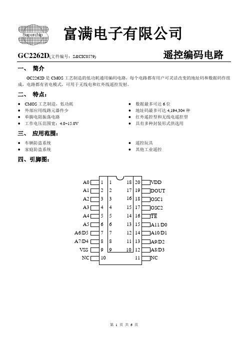
GC2262D
OSC
48KHz 73KHz 104KHz
PAD 图
TEB A11 A10 A9 A8
VSS
A7
A6
/D0 /D1 /D2 /D3
/D4
/D5
A5
IC衬底接VSS
A4
OSCO OSCI
DOUT VDD
A0
A1
A2 A3
No PAD Name
X
1
TEB
54.00
2 A11/D0 204.00
3 A10/D1 354.00
T o GC2262 D5 D4 D3
D2 1K-4.7K
D1 D0
10K*6
A0
VDD
B
A1
DOUT
Rosc
A2
OSC1
A3
OSC2
A4
TE
A5
D0
D5
D1
D4
D2
VSS
D3
A
1
2
3
第4页共7页
富满电子有限公司
GC22632D(文件编号:S&CIC0574 9)
(4)
VDD 1K-4.7K
D5 D4 D3 D2 D1 D0
4
A9/D2
504.00
5
A8/D3
654.00
6
VSS
817.00
7
A7/D4
966.00
8
A6/D5
1114.00
9
A5
1084.00
Y 706.00 706.00 706.00 706.00 706.00 706.00 706.00 706.00 449.10
No PAD Name
无线编码芯片2262
无线编码芯片22622008-02-27 19:09编写:建锋电子/jfdz 2008/02/27 /jfdzmcu概述PT/SC/BHM2262是一种CMOS工艺制造的低功耗低价位通用编解码电路是目前在无线通讯电路中作地址编码识别最常用的芯片之一。
2262将从数据和地址输入管脚并行输入的“地址/数据”转换为串行的、适用于RF或IR调制的波形,由DOUT管脚输出。
2262最多可有12位三态地址,提供531441(3的12次方)个地址码,减少了地址码冲突的可能性,提高了抗非法代码扫描的能力。
2262最多可有6位(D0-D5)数据端管脚。
特点1、CMOS 技术 5、宽范围的工作电压:Vcc=3V--12V2、低功耗非常高的抗噪声能力 6、仅外接一个电阻构成振荡器3、最多12位三态地址 7、DIP或SOP封装4、最多6数据应用1、汽车安全系统 4、家用安全系统/自动控制系统2、房门控制器 5、遥控玩具3、遥控风扇 6、工业遥控2262引脚图管脚说明管脚说明功能说明当TE_置“0”时,2262将从A0~A5和A6/D5~A11/D0管脚输入的“地址/数据”转换为专用的波形由DOUT输出。
DOUT输出提供给RF调制器或IR转换器,然后用无线电波或红外线将“地址/数据”信息发射出去。
发射的无线电波或红外线被RF解调器或IR接收器接收并恢复为原波形。
然后,2272对波形译码。
如果地址正确,就将其中的数据由相应管脚输出。
至此,完成了一次编解码。
RF操作代码位代码位是编码波形的基本成分。
分为AD(地址/数据)位和SYNC(同步)位两种。
地址/数据(AD)位波形一个AD位能被设置为“0”、“1”或“f”,分别对应“低电平”、“高电平”和“浮空”状态。
一位波形由2个脉冲周期组成。
每个脉冲周期持续时间为16个OSC(主频)周期。
参见下图:地址/数据(AD)位波形由上面我们可以看到,每一位码位都是从低电平开始到高电平,到低电平,再到高电平。
HX2262遥控芯片
HX2262/2272一对遥控编、解码电路:一、描述:HX2262/2272 是一对遥控编、解码电路,该芯片组采用CMOS工艺。
把数据和管脚址通过编码形成串行码,用于RF或者IR模式应用。
HX2262有最多可达12比特的三态地址管脚,可提供531,441地址码,由此大大减低了任何错码和串码的可能性。
二、特征:*CMOS技术*低功耗*高信噪比*高达12个三态码地址管脚*可有6个数据管脚*宽工作电压范围:3~18V*锁存或瞬时输出*DIP封装*RC振荡器三、应用*轿车保安系统*居家保安/自动化系统*车库门控制器*电扇遥控*玩具遥控*工业遥控用。
四、管脚功能表五、极限参数六、电气参数(除非特殊说明,Tamp=25℃,VDD=12.0V)七、外形图及测试应用图HX2262HX2272遥控解码电路一、描述:HX2272 / 2262 是一对遥控编、解码电路。
该芯片组采用CMOS工艺。
把数据和管脚址通过编码形成串行码,用于RF或者IR模式应用。
HX2272有最多可达12比特的三态地址管脚,可提供531,441地址码,由此大大减低了任何错码和串码的可能性。
同时HX2272对应不同的应用可有不同的选择:多种数据输出管脚组;锁存输出;瞬间输出。
二、特征:*CMOS技术*低功耗*高信噪比*高达12个三态码地址管脚*可有6个数据管脚*宽工作电压范围:3~18V*锁存或瞬时输出*DIP封装*RC振荡器三、应用*轿车保安系统*居家保安/自动化系统*车库门控制器*电扇遥控*居家保安/自动化系统*玩具遥控*工业遥控用四、管脚功能表五、极限参数(Templ=25℃)六、电气参数(除非特殊说明,Temp=25℃,Vcc=100)七、外形图及测试应用图。
- 1、下载文档前请自行甄别文档内容的完整性,平台不提供额外的编辑、内容补充、找答案等附加服务。
- 2、"仅部分预览"的文档,不可在线预览部分如存在完整性等问题,可反馈申请退款(可完整预览的文档不适用该条件!)。
- 3、如文档侵犯您的权益,请联系客服反馈,我们会尽快为您处理(人工客服工作时间:9:00-18:30)。
ą
CERAMIC FLATPACK (U) — — — — — TLV2262AMU TLV2262MU
† The D packages are available taped and reeled. Add R suffix to device type (e.g., TLV2262CDR). ‡ The PW package is available only left-end taped and reeled. § Chips are tested at 25°C. TLV2264 AVAILABLE OPTIONS PACKAGED DEVICES TA −40°C to 125°C −40°C to 125°C −55°C to 125°C VIOmax AT 25°C 950 µV 2.5 mV 950 µV 2.5 mV 950 µV 2.5 mV SMALL OUTLINE (D) TLV2264AID TLV2264ID TLV2264AQD TLV2264QD — — CHIP CARRIER (FK) — — — — TLV2264AMFK TLV2264MFK CERAMIC DIP (J) — — — — TLV2264AMJ TLV2264MJ PLASTIC DIP (N) TLV2264AIN TLV2264IN — — — — TSSOP (PW) TLV2264AIPWLE — — — — — CERAMIC FLATPACK (W) — — — — TLV2264AMW TLV2264MW
VOH − High-Level Output Voltage − V
3 2.5 TA = 125°C 2 TA = 25°C 1.5 1 TA = 85°C TA = − 40°C TA = − 55°C
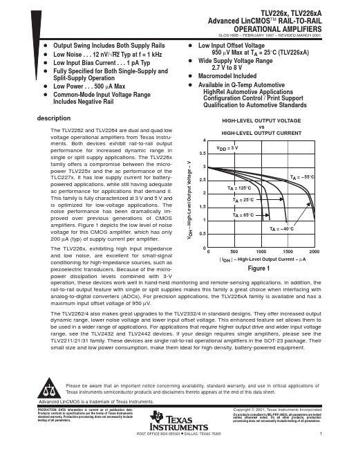
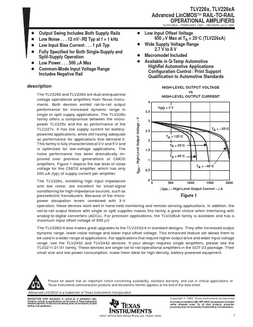
0 The TLV226x, exhibiting high input impedance 0 500 1000 1500 2000 and low noise, are excellent for small-signal | IOH | − High-Level Output Current − µ A conditioning for high-impedance sources, such as Figure 1 piezoelectric transducers. Because of the micropower dissipation levels combined with 3-V operation, these devices work well in hand-held monitoring and remote-sensing applications. In addition, the rail-to-rail output feature with single or split supplies makes this family a great choice when interfacing with analog-to-digital converters (ADCs). For precision applications, the TLV226xA family is available and has a maximum input offset voltage of 950 µV.
D Low Input Offset Voltage D D D
950 µV Max at TA = 25°C (TLV226xA) Wide Supply Voltage Range 2.7 V to 8 V Macromodel Included Available in Q-Temp Automotive HighRel Automotive Applications Configuration Control / Print Support Qualification to Automotive Standards
ÁÁ ÁÁ
0.5
The TLV2262/4 also makes great upgrades to the TLV2332/4 in standard designs. They offer increased output dynamic range, lower noise voltage and lower input offset voltage. This enhanced feature set allows them to be used in a wider range of applications. For applications that require higher output drive and wider input voltage range, see the TLV2432 and TLV2442 devices. If your design requires single amplifiers, please see the TLV2211/21/31 family. These devices are single rail-to-rail operational amplifiers in the SOT-23 package. Their small size and low power consumption, make them ideal for high density, battery-powered equipment.
PRODUCTION DATA information is current as of publication date. Products conform to specifications per the terms of Texas Instruments standard warranty. Production processing does not necessarily include testing of all parameters. On products compliant to MILĆPRFĆ38535, all parameters are tested unless otherwise noted. On all other products, production processing does not necessarily include testing of all parameters.
TLV226x, TLV226xA Advanced LinCMOS RAILĆTOĆRAIL OPERATIONAL AMPLIFIERS
TLV2262 AVAILABLE OPTIONS PACKAGED DEVICES TA 0°C to 70°C −40°C to 125°C −40°C to 125°C −55°C to 125°C VIOmax AT 25°C 2.5 mV 950 µV 2.5 mV 950 µV 2.5 mV 950 µV 2.5 mV SMALL OUTLINE (D) TLV2262CD TLV2262AID TLV2262ID TLV2262AQD TLV2262QD — — CHIP CARRIER (FK) — — — — — TLV2262AMFK TLV2262MFK CERAMIC DIP (JG) — — — — — TLV2262AMJG TLV2262MJG PLASTIC DIP (P) TLV2262CP TLV2262AIP TLV2262IP — — — — TSSOP (PW) TLV2262CPWLE TLV2262AIPWLnstruments Incorporated
POST OFFICE BOX 655303
• DALLAS, TEXAS 75265
1
元器件交易网
SLOS186B − FEBRUARY 1997 − REVISED MARCH 2001
Please be aware that an important notice concerning availability, standard warranty, and use in critical applications of Texas Instruments semiconductor products and disclaimers thereto appears at the end of this data sheet. Advanced LinCMOS is a trademark of Texas Instruments.
元器件交易网
ąą
TLV226x, TLV226xA Advanced LinCMOS RAILĆTOĆRAIL OPERATIONAL AMPLIFIERS
SLOS186B − FEBRUARY 1997 − REVISED MARCH 2001
D D D D D D
Output Swing Includes Both Supply Rails Low Noise . . . 12 nV/√Hz Typ at f = 1 kHz Low Input Bias Current . . . 1 pA Typ Fully Specified for Both Single-Supply and Split-Supply Operation Low Power . . . 500 µA Max Common-Mode Input Voltage Range Includes Negative Rail
HIGH-LEVEL OUTPUT VOLTAGE vs HIGH-LEVEL OUTPUT CURRENT
4 VDD = 3 V 3.5
description
The TLV2262 and TLV2264 are dual and quad low voltage operational amplifiers from Texas Instruments. Both devices exhibit rail-to-rail output performance for increased dynamic range in single or split supply applications. The TLV226x family offers a compromise between the micropower TLV225x and the ac performance of the TLC227x. It has low supply current for batterypowered applications, while still having adequate ac performance for applications that demand it. This family is fully characterized at 3 V and 5 V and is optimized for low-voltage applications. The noise performance has been dramatically improved over previous generations of CMOS amplifiers. Figure 1 depicts the low level of noise voltage for this CMOS amplifier, which has only 200 µA (typ) of supply current per amplifier.
