PID Tuning Rules for Second Order Systems
10 Analysis of Some PID Tuning Techniques

Case 1: r > 1.2. In this case, we have 0 < fcp < ^ Then the stabilizing set is given either by Fig. 8.6(a) or by Fig. 8.6(b). Notice from (10.6) that the parameter kd is always less than j as illustrated in Fig. 10.2. The derivative gain value provided by the Ziegler-Nichols method is robust in the sense that it is not close to the stability boundary j . Following the same principle, we would like to guarantee that the integral gain value is also far away from the stability boundary. __ Let xi be the fc^-coordinate of the point where the line kd = kd intersects the line kd = miki-\-bi. From Fig. 10.2, we now find the conditions under
k
பைடு நூலகம்
-i
- a i sin(Q;i) — cos(ai)
T
(10.4)
where ai is now the solution of the equation tan(a) = ^ ^ a 1+ r
linux调度原理

linux调度原理
Linux调度原理是指操作系统在多个进程间分配处理器资源的方法。
Linux使用CFS(Completely Fair Scheduler)调度器来实现公平调度。
CFS调度器基于时间片轮转的思想,将处理器时间划分成一小段一小段的时间片,并按照公平的方式分配给各个进程。
每个进程都拥有一个不断递增的虚拟运行时间,CFS根据进程的虚拟运行时间来决定下一个运行的进程。
CFS调度器通过维护一个红黑树来管理所有的进程,红黑树的节点表示各个进程的虚拟运行时间。
每次调度时,CFS会选择具有最小虚拟运行时间的进程运行,保证每个进程都能公平地获取处理器资源。
为了提高CPU利用率,CFS还实现了一种叫做负载均衡的机制。
当某个CPU的负载过高时,CFS会将正在运行的进程重新分配到空闲CPU上,以实现负载均衡。
这样可以最大程度地利用系统的处理能力。
除了公平调度,CFS还具备实时调度的能力。
CFS使用了一种称为类似于Earliest Deadline First(EDF)的策略来处理实时任务。
实时任务会被放置在一个专门的队列中,CFS会优先调度实时任务,以保证其满足严格的截止时间要求。
总结来说,Linux调度器使用CFS实现了公平和实时任务的调度。
它通过基于时间片轮转的方式,根据进程的虚拟运行时间
决定下一个运行的进程,并通过负载均衡机制提高CPU利用率。
此外,CFS还使用类似于EDF的策略来处理实时任务。
这些机制共同作用,确保系统能够高效地利用处理器资源,以满足各个进程的需求。
centos 进程管理打分

centos 进程管理打分CentOS 是一种流行的 Linux 操作系统,广泛用于服务器和个人电脑。
在CentOS 系统中,进程管理是非常重要的,可以帮助用户监控和控制系统中正在运行的进程,确保系统正常运行并提高系统的性能。
在本文中,我们将介绍 CentOS进程管理的相关知识,包括如何查看系统中的进程、如何终止进程、如何调整进程优先级等。
首先,要查看系统中正在运行的进程,可以使用命令 ps。
ps 命令可以显示系统中当前的进程情况,包括进程ID、进程状态、CPU 占用率、内存占用率等信息。
可以使用 ps aux 命令查看所有进程的详细信息,也可以使用 ps -ef 命令查看进程树的结构。
通过查看进程信息,可以及时发现系统中可能存在的问题,并采取相应的措施进行处理。
其次,要终止一个进程,可以使用 kill 命令。
kill 命令可以向指定的进程发送信号,通知进程终止。
可以使用 ps aux 命令查看要终止的进程的进程 ID,然后使用 kill 命令加上进程 ID,即可终止指定的进程。
如果要强制终止进程,可以使用kill -9 命令,该命令会立即终止进程,但可能会导致进程数据丢失,需要谨慎使用。
此外,要调整进程的优先级,可以使用 renice 命令。
renice 命令可以改变进程的优先级,进程的优先级越高,系统分配给进程的 CPU 时间就越多。
可以使用 ps aux 命令查看进程的进程 ID,然后使用 renice 命令加上进程 ID,再加上要调整的优先级值,即可改变进程的优先级。
调整进程的优先级可以提高系统的性能,确保重要进程能够得到足够的资源,提高系统的响应速度。
综上所述,CentOS 进程管理是系统运维中的重要内容,通过正确的进程管理,可以提高系统的稳定性和性能,确保系统正常运行。
通过查看进程、终止进程、调整进程优先级等操作,可以及时发现和解决系统中的问题,保证系统的正常运行。
希望以上内容可以帮助您更好地了解 CentOS 进程管理的相关知识,进而更好地管理您的系统。
pid参数整定方法(PIDparametertuningmethod)
pid参数整定方法(PID parameter tuning method)PID parameter tuning methodIn view of the combined device instrument loop control rate is relatively low, most of the circuit is operated manually, which not only increases the operator's workload, but also have a certain impact on the quality of the products, especially the preparation of a PID parameter tuning method.First, modify the PID parameter must have "SUPPERVISOR" and above permissions, permissions with the keyboard keyHandover permission, the key has been sent to a joint director Chen Sheng hands;Two, open the modified control loop detail screen, turn to the page shown below, modify the PID control backThe three parameters of the path setting are K, T1, T2;Three, the meaning of the PID parameter representsK: proportional gain (amplification), ranging from 0 to 240;T1: integral time, the range is 0 to 1440, the unit is minutes, and the 0 represents no integral action;T2: differential time, the range is 0 to 1440, the unit is minutes, and the 0 represents no differential action.Four, the role of PID parameters(1) the characteristics of proportional adjustment: 1, the adjustment function is quick, the system appears a deviation, the regulator immediately amplifies the deviation K times; and 2, the system has residual.The smaller the K transition process is more stable, but more than the larger difference; the increase of K, residual error will be reduced, but can not completely eliminate the residual error, can only play the role of coarse, but K is too large, the transition process is easy oscillation, K is too large, there may be divergence oscillation.(2) the characteristics of integral regulation: regulation and output change integral input deviation is proportional to the integral and integral function can eliminate the residual error, but reduces the stability of the system, T1 changes from big to small, integral effect from weak to strong, eliminate the residual capacity only from weak to strong, the elimination of bias, the output will stop change.(3) the characteristics of the differential regulation of the output differential regulation is regulated variable rate is proportional to, can improve the quality control in the introduction of differential effect, but the differential effect is too strong, will sometimes open and closed by the control valve, so T2 can not take too much, when T2 increases. Differential effects of capacity lag from weak to strong, has obvious effect, but the effect of no delay.Five. If you want to know how the control loop works, you canenter the detailed picture of the control loop and enter the page shown below:Among them, "CTLACTN" represents the mode of action of the controller, and "REVERSE" means reaction, and "DIRECT" represents the positive function.Six 、 controller selection method(1) the choice of P controller: it is suitable for controlling the system with smaller channel delay, little load change, and allowing the controlled quantity to vary within a certain range;(2) the selection of PI controller: it is suitable for the control system with less delay and little load change, and the controlled quantity is not allowed to be surplus;(3) the choice of PID controller: it is suitable for the control system, such as temperature control system, which has large load change, large capacity delay and high quality control requirements.Seven, PID parameter tuning methodIn engineering applications, empirical test method is adopted.The empirical method is most practical in practice. In setting parameters, the system response must be carefully observed, and the parameters are adjusted according to the response of the system. To observe the response of the system, you can look atthe real-time trend curve in the control loop detail screen, and the decay curve is preferably 4:1, that is, the ratio between the previous peak and the latter peak is 4:1.Experience value: in actual debugging, you can only set an experience value roughly, and then modify it according to the adjustment effect. The P here represents the degree of proportionality, P = 1/K.Parameter rangeControl systemP (1 / K)KT1 / MinT2 / Minlevel20% to 80%1.25 to 5--pressure30% to 70%1.43 to 3.40.4 to 3-flow40% to 100%1 to 2.50.1 to 1-temperature20% to 60%1.7 to 5From 3 to 100.3 to 1In short, in the whole time can not let the system appeardivergent oscillation, such as divergence oscillation, should be immediately cut for the manual, etc. system stability decreases after amplification, increase or decrease the differential integral time time again to switch to automatic control.The smaller the amplification is, the more stable the transition process is, but the larger the residual error is. The larger the amplification is, the easier the oscillation occurs during the transition. The smaller the integration time, the faster the elimination of the residual difference, but the system oscillation will be larger, and the larger the integration time, the slower the system will eliminate the residual error. The differential time is too large, the system oscillation frequency increases, the regulation time increases, the differential is too small, the system regulation is slow.Steps of the method of controller parameter testing:Because the ratio is controlled, so the basic proportion, trying to be good, the transition process has been basically stable, and then add the integral eliminateresidual error finally joined the differential role to further improve the quality control, the basic steps are as follows:(A) for the P controller, the magnification is placed in a smaller position, and the K is gradually increased. The transition process curve of the controlled quantity is observed until the curve is satisfied;(B) the PI controller, the first set of T1=0, according to theproportion of the role of pure tuning amplification to achieve 4:1 attenuation curve; then K reduced (10 ~ 20%), the integral time T1 from large to small gradually added, until the decay process of 4:1;(C) of PID controller, T2 = 0; according to the PI effect of trying setting procedures K, T1 parameters, and then the magnification increases to more than the original large (10 ~ 20%), after T1 also reduced properly to T2 increases gradually, observe the transition curve, until a satisfactory. Through the process of.In a word: when setting parameters, we should carefully observe the system output and the amount of change, and then modify the PID parameters according to the specific conditions. It can be said that as long as process technicians spend more time, most control systems adopt PID regulation to meet the requirements.Eight 、 series pole control loop settingThe setting of the cascade control circuit can be accomplished by two steps, that is, setting the secondary circuit first, then setting the main loop, or adopting a one step method, that is, setting the main and auxiliary circuits simultaneously.(1) when the experience value of the secondary circuit is used as the following value, the general auxiliary circuit only uses proportional control:Secondary variableMagnification factor (K)Degree of proportionality (P)temperature5 to 1.720% to 60%pressure3 to 1.430% to 70%flow2.5 to 1.2540% to 80%level5 to 1.2520% to 80%(2) cascade control loop system is put into operation, and then the parameters of the main controller are adjusted according to the single loop control system parameter tuning method;(3) if there is "resonance" in the tuning process, only the main and auxiliary controller decreases the magnification can be eliminated, if the resonance is too intense, the first switch to manual production, to be stable after re operation, re setting.In conclusion, P is the most basic control function. After adding I, it can control the difference and improve the control accuracy. Adding D can improve the quality of control.Nine, matters needing attention(1) the parameter tuning before calibration of sensors and actuators, ensure the instrument is normal, you can just getDynamic control test, manual state measurement parameters should be stable and reliable.(2) setting the K parameter according to the experience value, turning off the integral adjustment temporarily, and switching to the automatic observation step response,It should be noted that the output of the controller, to determine what is not the negative feedback circuit (wiring design and check whether there are loopholes, when new system debugging will encounter this kind of situation, such as: the need to close the opening of the regulator, it is to enlarge the degree);(3) to ensure the stability of the process when settingparameters, it should be cut immediately when the product quality and process parameters are affectedManual control,When the process is stable, the PID parameter is automatically modified.(4) if it is a cascade and proportional control loop, we must first make a loop, a loop setting, we should also pay attention to the firstThe principle of inner ring, outer back and outer ring.(5) when manually cut to the automatic, make sure that the given value is approximately consistent with the measured value, but for a combinationHoneywell DCS does not have this problem; when manually, the given value automatically tracks the measurements.Ten 、 PID parameter setting shorthandTo find the optimal parameter setting, check the order from small to greatFirst proportion, then integral, and finally add differential additionThe oscillation curve is very frequent, put a small magnificationFloating around the curve magnification to a WAN,The curve deviates slowly and the integration time drops The curve fluctuates long and the integral time is longer The curve oscillates with a frequency that falls off first Moment to slow wave, differential time should be lengthenedThe ideal curve has two waves, the front high and the rear 1, and the lower 4A look at two tones, more analysis, the quality of regulation will not be lowEleven typical control loop1 、 single loop control:(1) control valve action mode selection principle:Control valve in accordance with the role of gas distribution, gas off two. The air opening valve is opened with the increase of the signal pressure, and has no letterNo. when the valve in the fully closed state; on the other hand, with the increase of signal pressure, the valve gradually closed, no signal when the valve is fully open state for gas off valve.The selection principle is mainly from the safety of production, from the guarantee of product quality, from the loss of raw materials and power, from the characteristics of the media to consider these aspects.(2) selection of controller action mode:Selection principle: make the whole single loop constitute negative feedback system.Regulations:Control valve: gas open for "+", "gas off" type -";Controller: the positive action is "+", and the reaction is "" -";Object: when the material or energy increases through the control valve, according to the process mechanism analysis, if the controlled quantity increases with "+", then decreases to "-"";Transmitter: generally considered as a positive link.Then the positive and negative selection discriminant of the controller is:(the controller is "+") (the control valve "+") (object "+") = "-"2 、 cascade loop control:In the single loop control system, it has been pointed out that the principle of selecting the positive and negative modes of the controller is to make the whole control system constitute a negative feedback system, and the discriminant of "product is negative" is given. This criterion is also applicable to the choice of the positive and negative modes of the primary and secondary controllers in the cascade control system.(1) main controller action mode selection:(main controller +) (sub object +) (main object =) = (-)So when the main and auxiliary variables change in the same direction, the main controller should be counterproductive, reversal is the role of Party A.Type.(2) acting mode selection of auxiliary controller:(auxiliary controller +) (control valve +) (secondary object =) = (-)(3) cascade control loop is put into operation:The operation of the utility model is to transfer the master and the auxiliary controllers from the manual operation state to the working state through proper stepsState. Operation method of cascade control system, there are two kinds: one is the first deputy after the main ring ring; the other is the first investment after the main ring ring. Operation method is widely used for the first time, put into operation to ensure the switch without disturbance, because the Honeywell DCS with PV automatic tracking function so basically can switch without disturbance, and the operation is relatively simple.3, split control systemThe split control system is the output signal of a controller to control two or more control valves, each of themThe control valve works only within a signal of the entire range of the output signal.That is, multi valve and sub pass.The implementation method mainly uses two kinds: one is through each control valve positioner, two is through the DCS software realization, in the use of DCS control, we usually through the DCS configuration implementation.In process control system, in accordance with the control valve of the gas switch action and gas can be divided into two categories: one is the same as the action to the valve, the control valve input signal increases or decreases, the valve open or open, the other is different to the valve action, as control valve input signal increases or decreases, the valve is always according to a valve closed and another valve openingdirection of action. The choice of the same or opposite direction of the control valve is determined by the need of the process. As detailed below:4, ratio control loopA ratio control circuit is a system that automatically maintains a certain proportion of two or more of the two materialsThe amount of material from the raw material with the amount of change according to a certain ratio, such as gas waste heat boiler and air intake volume is proportional to the combustion of the boiler to achieve the best effect.。
几种pid整定方法的比较

Ioan Naşcu1, Robin De Keyser2, Silviu Folea1, Tudor Buzdugan1
1 Technical University of Cluj Napoca, Department of Automation, Ioan.Nascu@aut.utcluj.ro, Tudor.Buzdugan@aut.utcluj.ro, Silviu.Folea@aut.utcluj.ro
(3)
Ti
= 2ζτ , Td
= τ2 2ζτ
,Tf
= Tc 2 2Tc +θ
thus resulting in the closed-loop transfer function:
M 2 = a2 + b2 = M ′2M ′′2 = (a′2 + b′2e the PID controller we will approximate e-θs by
(1-θs) and using the well-known IMC-PID design method we
then obtain:
Kc
=
2ζτ k p (2Tc + θ )
brought to steady-state conditions in manual control or with
any preliminary tuned PID controller.
The process Hp is assumed to be linear, stable and proper. The PID controller has a non-interacting structure cascaded
linux磁盘调度策略
linux磁盘调度策略Linux磁盘调度策略磁盘调度策略是操作系统中的一个重要组成部分,它决定了磁盘上的数据访问顺序。
Linux操作系统提供了多种磁盘调度策略,以满足不同场景下的需求。
本文将介绍Linux中常见的磁盘调度策略,包括CFQ、Deadline和NOOP。
1. CFQ磁盘调度策略CFQ(Completely Fair Queuing)是Linux内核默认的磁盘调度策略。
它采用了时间片轮转的方式,为每个进程提供公平的磁盘访问机会。
CFQ会将磁盘请求按照优先级进行分类,并为每个进程分配一定数量的时间片进行磁盘访问。
优先级高的进程会获得更多的时间片,从而获得更快的磁盘响应速度。
CFQ适用于大多数常规应用场景,能够保证公平性和稳定性。
2. Deadline磁盘调度策略Deadline磁盘调度策略以最小化磁盘请求的响应时间为目标。
它将磁盘请求分为两类:实时请求和普通请求。
实时请求具有更高的优先级,需要在规定时间内完成。
而普通请求则在规定时间内按照先进先出的原则进行处理。
Deadline通过维护两个队列,分别处理实时请求和普通请求,以保证实时请求的响应时间。
3. NOOP磁盘调度策略NOOP磁盘调度策略是一种简单的FIFO(先进先出)调度策略。
它不对磁盘请求进行排序,直接按照请求的先后顺序进行处理。
NOOP适用于低负载的系统,可以减少磁盘调度的开销,提高系统的响应速度。
4. 其他磁盘调度策略除了CFQ、Deadline和NOOP,Linux还提供了其他一些磁盘调度策略,如Anticipatory、AS(Anticipatory Scheduler)和BFQ (Budget Fair Queuing)等。
这些策略在特定场景下有着不同的表现和优势。
例如,Anticipatory策略在读取大文件时表现较好,而AS策略则适用于多媒体和数据库等需要低延迟的应用。
5. 磁盘调度策略的选择选择合适的磁盘调度策略需要根据具体的应用场景和需求来决定。
内模控制框架下时延系统扩张状态观测器参数整定

内模控制框架下时延系统扩张状态观测器参数整定徐琦;孙明玮;陈增强;张德贤【摘要】作为一种有效的控制设计方法,自抗扰控制研究获得了广泛关注,然而针对自抗扰控制器的参数整定方法则相对较少.本文针对一阶惯性加延迟系统,将线性自抗扰控制转化为内模控制结构,导出了其中控制器、滤波器、乘性不确定性、互补灵敏度函数的对应表达式,随后,利用频域鲁棒稳定性判据,分析了自抗扰控制器核心——扩张状态观测器的参数对闭环系统稳定性的影响.基于该分析,总结出一阶惯性加延迟系统扩张状态观测器的两条参数整定准则.数值仿真结果验证了该整定准则的有效性.【期刊名称】《控制理论与应用》【年(卷),期】2013(030)012【总页数】5页(P1641-1645)【关键词】自抗扰控制;扩张状态观测器;内模控制;时延;稳定性【作者】徐琦;孙明玮;陈增强;张德贤【作者单位】南开大学电子信息与光学工程学院,天津300071;军事交通学院,天津300161;南开大学计算机与控制工程学院,天津300071;南开大学计算机与控制工程学院,天津300071;南开大学电子信息与光学工程学院,天津300071【正文语种】中文【中图分类】TP2731 引言(Introduction)自抗扰控制(active disturbance rejection control,ADRC)技术是一种基于干扰观测器的控制策略,它继承和发扬了经典PID控制的思想,近年来,获得了学者们的广泛关注[1-2].自抗扰控制器的核心--扩张状态观测器(extended state observer,ESO)利用系统的输入输出数据,将系统的内外扰动总和估计并进行动态补偿,使原系统简化为近似的串联积分器形式,从而达到理想的控制效果,在实际工业领域,自抗扰控制技术已经获得了一些成功的应用[3-5].自抗扰控制技术是一种基于干扰观测器的控制系统设计方法,最初是由韩京清以一种复杂的非线性形式提出的[2],其参数整定过程和稳定性分析都比较复杂[6].虽然自抗扰控制系统闭环稳定性分析工作已经取得了较大的进展[7-9],然而对于实际工程师有价值的控制参数整定方法仍相对较少[10-11].从促进推广自抗扰控制应用的角度来看,开发出正确有效的参数整定方法是非常重要的.为简化参数调节过程,Gao开发了一种线性自抗扰控制器设计方法[12],这种简洁的自抗扰控制结构含有更少的控制参数并且易于实现[13-14],对于实际中各类典型的工业过程,也便于更加深入的分析和探寻其控制参数调节方法.针对代表了一大类实际工业过程的一阶时延系统,PID控制器的参数整定方法已经比较完善[15-17].作为PID控制继承和发扬者的自抗扰控制技术,在实践中针对一阶时延对象也取得了良好的控制效果,然而其参数整定方法研究却相对较少,此类整定方法的出现将会促进自抗扰控制的进一步广泛应用.作为一种提高常规控制系统设计水平的有力工具,内模控制(internal model control,IMC)[18-20]不仅是一种实用的先进控制算法,而且是研究预测控制等控制策略的重要工具.在内模控制框架内,许多控制器参数整定方法被开发出来[21-22].本文针对自抗扰控制器的核心组件--扩张状态观测器,在内模控制框架内进行稳定性分析,推导出一阶时延对象的控制参数整定准则.最后通过数值仿真验证该整定准则的正确性和有效性.2 ESO的内模控制形式构造(Reformulation of ESO within the framework of IMC)考虑一阶时延系统其中:u表示系统输入,y表示系统输出,k表示系统的稳态增益,T为系统的时间常数,τ为系统的时延.利用Padé近似,得到根据式(2),系统(1)可以转化为其中g(t)为Padé近似所引入的近似误差.将式(3)两边同时进行2次积分得到其中:式(5)中t0和t c分别表示系统的初始时刻和当前时刻.显然时延对象(1)可以被转化为式(4)所表示的不含时延对象.定义x 1=y,x 2=f(t),式(4)可表达为针对式(6)设计线性状态观测器由于状态观测器(7)是在原始对象(1)的基础上扩充出一个新的状态变量而导出的,所以式(7)称为扩张状态观测器.其中z1表示估计的系统状态x1,z2表示估计的系统内外扰动总和,b和ωo为扩张状态观测器的可调参数,分别称为扩张状态观测器的增益和带宽.性能良好的扩张状态观测器可以使z2理想的跟踪系统的扰动总和x 2,这种情况下,控制律可以选取为其中:y r为指令信号,k p和k d分别表示PD控制器的控制参数[12].整理式(7)可以得到根据式(8)-(9),一阶时延对象的自抗扰控制系统结构如图1所示.图1 一阶时延对象自抗扰控制系统结构Fig.1 ADRC structure of first-order-plus-time-delay plant经过等效变换,图1虚线框中的扩张状态观测器部分可转化为图2所示形式.图2 扩张状态观测器的内模控制形式Fig.2 IMC structure of the ESO图2表明,图1虚线框内对象和ESO构成的环路部分可以被转化为典型的内模控制系统[19].该内模控制系统的输入为“外环PD控制器的输出”,该内模控制系统的输出为“对象输出的一阶微分”.这样,一阶时延对象的自抗扰控制系统结构就可以进一步表示成图3所示形式.图3自抗扰控制系统的内模控制结构Fig.3ThetransformationalstructureofADRCsystem图3 表明,在满足尺度分离定理情况下,性能足够好的ESO可以确保对象输出的一阶微分理想跟踪外环PD控制器的输出,此时,被控对象就被ESO转化成为近似的一阶积分器,这个一阶积分器的近似程度是由ESO性能决定的,而该一阶积分器近似程度的好坏也直接影响着自抗扰控制系统性能的优劣.3 ESO参数整定准则(TuningcriteriaforESO)根据图2,内模控制结构相应的对象部分Gp表达式为相应模型部分Gm表达式为相应控制器部分CIMC和滤波器部分FIMC表达式分别为根据式(10)-(11),得到系统的乘性不确定性lm表达式为根据式(11)-(13),系统互补灵敏度函数~η表达式为依据文献[18]中内模控制系统鲁棒稳定性判据,系统稳定时所需满足条件将式(14)-(15)代入到式(16)中,得到系统稳定性条件不失一般性,将对象参数k和T均取为1,稳定性条件表示为ESO参数ωo,b和对象时延τ对系统稳定性的影响可以通过Bode图以图形化的形式表达出来.其中互补灵敏度函数(ω)是一个典型的低通滤波器,ωo为滤波器的转折频率.将参数b固定为1,考察乘性不确定性lm(ω)在时延τ分别取值为0.5,1.0,1.5,2.0时的增益Bode图曲线如图4.将时延τ固定为1,考察乘性不确定性lm(ω)在b分别取值为0.5,1.0,1.5,2.0时的增益Bode图曲线如图5所示.图4 τ取值对|lm(ω)|的影响Fig.4Theeffectofτon|lm(ω)|图 5b取值对|lm(ω)|的影响Fig.5Theeffectofbon|lm(ω)|根据图4-5,利用Bode图曲线叠加原理,得到ESO参数ωo,b和对象时延τ对系统稳定性的影响.随着参数ωo的增大,(ω)的带宽向高频段延伸,sup|(ω)lm(ω)|大于1的可能性增大,系统的稳定性变差;图4表明随着对象时延τ的增大,lm(ω)幅值峰值出现的频率减小,sup|(ω)lm(ω)|大于1的可能性增大,系统的稳定性变差;图5表明随着参数b的增大,l m(ω)幅值峰值减小,sup |(ω)l m(ω)|大于1的可能性降低,系统的稳定性提升. 综合上述分析,针对一阶时延对象的扩张状态观测器参数整定准则总结如下:准则1 根据文献[11]中ESO带宽ωo与闭环期望调节时间t s的关系ωo≈40/t s 选择ωo.准则2 由于系统时延的影响,标称参数b值往往达不到系统的稳定性要求,需要增大ESO参数b值实现良好的控制性能.4 数值仿真(Numerical example)利用数值仿真验证上述参数整定准则的有效性.设被控一阶时延对象数学模型为控制任务为跟踪幅值为4,周期为10的方波信号.进行自抗扰控制器设计,PD控制器部分选取为比例控制器,控制参数为k p=2,设定期望的闭环调节时间t s=5 s,根据准则1,首先选取ESO带宽ωo=40/5=8,为验证准则2的有效性,分别将ESO参数b选取为模型标称值1,4和7,考察ESO带宽ωo取不同值时的系统响应曲线如图6-8所示.图6-8表明,对于时延系统,根据闭环性能指标选定的ωo值,标称b值达不到系统的稳定性要求,增大b值能够提高时延系统稳定性,实现期望的控制性能. 图6 b=1,ωo=8时系统响应曲线Fig.6 Time response when b=1,ωo=8图7 b=4,ωo=8时系统响应曲线Fig.7 Time response when b=4,ωo=8图8 b=7,ωo=8时系统响应曲线Fig.8 Time response when b=7,ωo=85 结论(Conclusions)针对工业过程中广泛存在的一阶时延对象,本文提出了一种将扩张状态观测器转化为内模控制结构进行分析的方法,利用内模控制鲁棒稳定性判据分析了ESO参数b,ωo和对象时延τ对系统稳定性的影响,总结出扩张状态观测器参数整定准则,以实现系统稳定性和动态性能的良好权衡.数值仿真结果表明该整定准则的有效性,具有较强的实践意义.参考文献(References):【相关文献】[1]黄一,薛文超.自抗扰控制:思想、应用及理论分析[J].系统科学与数学,2012,32(10):1287-1307.(HUANG Yi,XUE Wenchao.Active disturbance rejectioncontrol:methodology,applications and theoretical analysis[J].Journal of Systems Science and Mathematical Sciences,2012,32(10):1287-1307.)[2]韩京清.自抗扰控制技术[M].北京:国防工业出版社,2008.(HAN Jingqing.Active Disturbance Rejection Control Technique[M].Beijing:National Defense Industry Press,2008.)[3]DONG L,ZHANGY,GAO Z.A robust decentralized load frequency controller for interconnected power systems[J].ISA Transactions,2012,51(3):410-419.[4]王丽君,童朝南,李擎,等.实用自抗扰控制在大时滞厚度自动监控系统中的应用[J].控制理论与应用,2012,29(3):368-374.(WANG Lijun,TONG Chaonan,LIQing,et al.Practical active disturbance rejection solution for monitoring automatic gauge control system with large time-delay[J].Control Theory&Applications,2012,29(3):368-374.)[5]赖爱芳,郭毓,郑立君.航天器姿态机动及稳定的自抗扰控制[J].控制理论与应用,2012,29(3):401-407.(LAIAifang,GUO Yu,ZHENG Lijun.Active disturbance rejection control for spacecraft attitude maneuver and stability[J].Control Theory&Applications,2012,29(3):401-407.) [6]FREIDOVICH L B,KHALIL H K.Robust feedback linearization using extended high-gain observers[C]//Proceedings of IEEE Conference on Decision and Control.SanDiego:IEEE,2006,8:983-988.[7]GUO B,ZHAO Z.On the convergence of an extended state observer for nonlinear systemswith uncertainty[J].Systems&Control Letters,2011,60(6):420-430.[8]YOO D,YAU S S T,GAO Z.Optimal fast tracking observer bandwidth of the linear extended state observer[J].International Journal of Control,2007,80(1):102-111.[9]GUO B,ZHAO Z.On convergence of the nonlinear active disturbance rejection control for MIMO systems[J].SIAM Journal on Control and Optimization,2013,51(2):1727-1757.[10]李述清,张胜修,刘毅男,等.根据系统时间尺度整定自抗扰控制器参数[J].控制理论与应用,2012,29(1):125-129.(LIShuqing,ZHANG Shengxiu,LIU Yinan,et al.Parameter-tuning in active disturbance rejection controller using time scale[J].ControlTheory&Applications,2012,29(1):125-129.)[11]CHEN X,LID,GAO Z,et al.Tuning method for second-order active disturbance rejection control[C]//Proceedings of the Chinese Control Conference.Yantai:IEEE,2011,7:6322-6327.[12]GAO Z.Scaling and bandwidth-parameterization based controllertuning[C]//Proceedings of the American Control Conference.Denver:IEEE,2003,6:4989-4996.[13]SUNB,GAOZ.A DSP-based active disturbance rejection control design for a 1-kW H-bridge DC-DC power converter[J].IEEE Transactions on IndustrialElectronics,2005,52(5):1271-1277.[14]陈增强,孙明玮,杨瑞光.线性自抗扰控制器的稳定性研究[J].自动化学报,2013,39(5):574-580.(CHEN Zengqiang,SUN Mingwei,YANG Ruiguang.On the stability of linear active disturbance rejection control[J].Acta Automatica Sinica,2013,39(5):574-580.)[15]LEE Y,LEE J,PARK S.PID controller tuning for integrating and unstable processes with time delay[J].Chemical Engineering Science,2000,55(17):3481-3493.[16]PANDA C,YU C C,HUANG H P.PID tuning rules for SOPDT systems:review and some new results[J].ISA Transactions,2004,43(2):283-295.[17]HWANG C,HWANG J H.Stabilization of first-order plus dead-time unstable processes using PID controllers[J].IEE Proceedings on Control Theory andApplications,2004,151(1):89-94.[18]MORARI M,ZAFIRIOU E.Robust Process Control[M].New Jersey:Prentice Hall,1989.[19]GARCIA CE,MORARIM.Internal model control:1:a unifying review and some new results[J].Industrial&Engineering Chemistry Process Design andDevelopment,1982,21(2):308-323.[20]肖强,谢巍.针对时滞系统的一般化内模控制方法[J].自动化学报,2011,37(4):464-470.(XIAO Qiang,XIE Wei.A GIMC architecture for time-delay systems[J].Acta AutomaticaSinica,2011,37(4):464-470.)[21]GRIMBLE M J,DE LA SALLE S,HO D.Relationships between internal model control and LQG controller structures[J].Automatica,1989,25(1):41-53.[22]ALC´A NTARA S,ZHANG W,PEDRET C,et al.IMC-like analytical H∞design with S/SP mixed sensitivity consideration:utility in PID tuning guidance[J].Journal of Process Control,2011,21(6):976-985.。
如何应用Ziegler_Nichols(Z-N)法整定PID调节器的参数
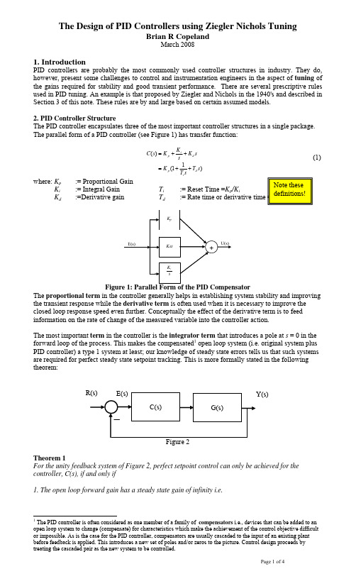
R(s)
E(s) C(s) G(s)
Y(s)
Figure 2 Theorem 1 For the unity feedback system of Figure 2, perfect setpoint control can only be achieved for the controller, C(s), if and only if 1. The open loop forward gain has a steady state gain of infinity i.e.
The Design of PID Controllers using Ziegler Nichols Tuning
Brian R Copeland
March 2008
1. Introduction
PID controllers are probably the most commonly used controller structures in industry. They do, however, present some challenges to control and instrumentation engineers in the aspect of tuning of the gains required for stability and good transient performance. There are several prescriptive rules used in PID tuning. An example is that proposed by Ziegler and Nichols in the 1940's and described in Section 3 of this note. These rules are by and large based on certain assumed models. 2. PID Controller Structure The PID controller encapsulates three of the most important controller structures in a single package. The parallel form of a PID controller (see Figure 1) has transfer function:
Linux下进程绑定多CPU运行
进程绑定多核运行名词CPU affinity:中文称作“CPU亲和力”,是指在CMP架构下,能够将一个或多个进程绑定到一个或多个处理器上运行。
一、在Linux上修改进程的“CPU亲和力”在Linux上,可以通过taskset命令进行修改。
运行如下命令可以安装taskset工具。
在CentOS/Fedora 下安装schedutils:# yum install schedutils在Debian/Ubuntu 下安装schedutils:# apt-get install schedutils如果正在使用CentOS/Fedora/Debian/Ubuntu 的最新版本的话,schedutils/util-linux 这个软件包可能已经装上了。
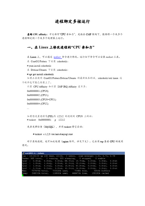
计算CPU Affinity 和计算SMP IRQ Affinity 差不多:0x00000001 (CPU0)0x00000002 (CPU1)0x00000003 (CPU0+CPU1)0x00000004 (CPU2)...如果想设置进程号(PID)为12212 的进程到CPU0 上的话:# taskset 0x00000001 -p 12212或者关掉任务(MySQL),并用taskset将它启动:# taskset -c 1,2,3 /etc/init.d/mysql start对于其他进程,也可如此处理(nginx除外,详见下文)。
之后用top查看CPU的使用情况。
二、配置nginx绑定CPU刚才说nginx除外,是因为nginx提供了更精确的控制。
在conf/nginx.conf中,有如下一行:worker_processes 1;这是用来配置nginx启动几个工作进程的,默认为1。
而nginx还支持一个名为worker_cpu_affinity的配置项,也就是说,nginx可以为每个工作进程绑定CPU。
我做了如下配置:worker_processes 3;worker_cpu_affinity 0010 0100 1000;这里0010 0100 1000是掩码,分别代表第2、3、4颗cpu核心。
基于Maclaurin展开的时间绝对误差积分次优时滞系统设计
基于Maclaurin展开的时间绝对误差积分次优时滞系统设计杨启文;阳外玲;薛云灿;杨远慧【摘要】A desired model of ITAE(integral time absolute error) optimal time-delay system is presented based on the canonical form of ITAE optimal system(ITAE-OS). By making use of Maclaurin expansion, a design method for ITAE suboptimal time-delay system(ITAE-STDS) is discussed. The comparison of the third order ITAE-STDS with ITAE-OS reveals their similar dynamic performance in frequency domain and time domain. Case studies in design of PID and the lead-lag compensator are given. Comparisons of step response, load rejection and parameter robustness show that the resulting systems have satisfactory performance by using the proposed method.%根据经典时间绝对误差积分(ITAE)最优系统标准型,给出了ITAE最优时滞系统的期望模型;利用Maclaurin展开技术,讨论了ITAE次优时滞系统的设计方法,并就ITAE次优和最优的三阶系统进行了频域和时域比较.论文最后给出了基于ITAE次优时滞系统的PID和超前滞后补偿器设计实例.阶跃响应、负载扰动以及参数鲁棒性方面的比较研究表明,本文方法能够获得十分满意的性能指标.【期刊名称】《控制理论与应用》【年(卷),期】2011(028)012【总页数】6页(P1831-1836)【关键词】ITAE最优控制;标准型;时滞系统;Maclaurin展开【作者】杨启文;阳外玲;薛云灿;杨远慧【作者单位】河海大学计算机与信息学院,江苏常州213022/江苏省输配电装备技术重点实验室,江苏常州213022;河海大学计算机与信息学院,江苏常州213022/江苏省输配电装备技术重点实验室,江苏常州213022;河海大学计算机与信息学院,江苏常州213022/江苏省输配电装备技术重点实验室,江苏常州213022;河海大学计算机与信息学院,江苏常州213022/江苏省输配电装备技术重点实验室,江苏常州213022【正文语种】中文【中图分类】TP2731 引言(Introduction)时滞特性是实际物理过程必然存在的一种现象.由于控制作用要经过一段时间滞后才能检测出来,从而增加了控制的难度,时滞系统也因此成为控制领域长期关注的焦点.时滞系统的设计,以一阶和二阶时滞对象为主[1~4],高阶时滞对象的直接设计方法并不多.尽管基于幅相稳定裕度的设计方法可用于高阶时滞对象,但由于高阶系统的频域指标与时域指标还缺乏直接的联系[5],因此,系统的性能在很大程度上依赖于设计经验.时间绝对误差积分(ITAE)是一种系统性能评价指标[6]:其中e(t)为系统误差.根据ITAE最小指标设计的系统,通常具有很好的时域性能指标(如超调量和调节时间),因此,很多文献根据ITAE准则或ITAE标准型进行系统设计[7~9].由于时滞因子e−Ls是一个超越函数,根据ITAE标准型进行有理化设计存在困难.将时滞因子e−Ls进行Pade逼近或Taylor展开尽管是一种有效的有理化方法,但有时也会造成系统性能恶化[1]甚至不稳定[10].因此,利用ITAE标准型进行时滞系统的设计,目前还缺乏一个有效的通用方法.本文针对ITAE标准型在时滞系统优化设计中的应用情况,以位移无静差系统为例,研究ITAE次优时滞系统(ITAE–STDS)设计方法,并通过PID以及超前滞后补偿器的设计实例进行仿真验证.2 ITAE次优时滞系统模型及分析(Model of ITAE–STDS and analysis)2.1 ITAE最优时滞系统期望模型(Expected model of ITAE optimal time-delay system)ITAE位移无静差系统的标准化模型通常可以描述为式中:R(s)和Y(s)分别为系统输入和输出;βi(i=1,2,3,···,n − 1)为标准型系数.ITAE最优标准型中的各项系数最早由Graham给出[11],后有学者进行修正[12].现有的研究表明,ITAE最优系统(1)具有很好的时域性能指标(超调量小、调节速度快、鲁棒性强)和满意的频域指标(如稳定裕度).对于一个时滞过程,若其期望的系统模型为则它的暂态响应过程与ITAE系统(1)的响应完全相同,只是在时间上滞后了L个时间单位.故将系统(2)称之为期望的ITAE最优时滞系统.2.2 ITAE次优时滞系统开环模型(Open-loop model of ITAE–STDS)在常见的单回路(假定为单位负反馈结构)系统中,设位移无静差时滞系统的开环传递函数(假设为I型系统)为式中:则相应的闭环传递函数为其中ΦL(s)=.由于(s)与ΦL(s)具有相同的稳态增益,即(0)=ΦL(0)=1,故将其进行Maclaurin展开:式中:令(s)与ΦL(s)各阶导数对应相等:这样,时滞系统(4)与ITAE最优时滞系统(2)就具有相似的中、低频增益特性,称之为ITAE次优时滞系统.由式(4)~(6)知其中ω0L=Lω0.利用式(7)就可以确定ITAE次优时滞系统开环模型GL(s)的各项系数.2.3 ITAE次优时滞系统分析(Analysis of ITAE–STDS)考虑如下形式的三阶开环时滞模型:由式(7)知:由式(1)可得三阶ITAE最优控制系统的开环标准型下面比较大时滞L=100时,ITAE次优时滞系统与ITAE最优系统的开环频域特性和闭环时域特性.a)开环频域分析.取ω0L=1,即ω0=0.01;参数βi采用文献[12]的修正系数:β1=2.17;β2=1.78.图1为三阶ITAE系统开环模型G(s)以及三阶次优时滞系统开环模型GL(s)的频率特性.从图1可以看出,在中、低频段,ITAE次优时滞系统的幅频特性稍低于ITAE最优系统,而在高频段,两者几乎完全相同.图1 开环频率特性比较Fig.1 Comparison of open-loop frequency characteristicsITAE最优系统的稳定裕度为一恒定值:增益裕度为11.7dB,相位裕度为66.7°,与ω0的选择无关;而ITAE次优时滞系统稳定裕度则与ω0L的选取有关.选取不同ω0L 时,ITAE次优时滞系统的稳定裕度如表1所示.当ω0L>1.5时,ITAE次优时滞系统的相角裕度小于60°.因此,一般取ω0L< 1.5,则ITAE次优时滞系统能够具有较满意的性能指标.表1 ITAE–STDS稳定裕度Table 1 Stability margin of ITAE–STDSω0L 增益裕度/dB 相位裕度/(°)0.5 8.2 65.7 1.0 7.5 63.6 1.5 7.1 61.2 2.0 6.7 58.8 2.5 6.156.6b)闭环时域分析.图2是单位阶跃信号作用下,三阶ITAE最优系统和ITAE次优时滞控制系统的闭环响应.为了比较二者的动态性能,ITAE最优系统的阶跃信号加入时间要晚100s.由阶跃响应曲线可以看出,二者的暂态响应过程几乎完全相同.当阶跃响应稳定后,加入一个幅值为0.5的单位阶跃扰动.为了比较二者的扰动响应过程,ITAE最优系统的扰动加入时间要晚100s.从扰动响应曲线可以看出,ITAE次优时滞系统只是在时间上较ITAE最优系统延迟了一个时滞时间L,而动态响应过程也几乎相同.二者抗扰性能的相似性是由它们开环稳定裕度的相似性决定的.图2 单位阶跃响应及负载扰动响应比较Fig.2 Comparison of unit Stepresponses and load disturbance responses3 ITAE次优时滞系统设计(Design of ITAE–STDS)控制系统的设计,首先必须确定控制器类型,然后根据系统性能指标要求确定控制器参数.3.1 镇定控制器的存在条件(The existence condition of stabilization controller) 稳定性一直是系统设计中的一个重要的问题.引入控制器的首要条件是能否实现系统镇定.引理1 对于伪多项式式中:L1< L2<···< Lr,L1+Lr> 0,主导项(对应于s的最高次幂和最大的Lj)系数h0r/=0.如果H(s)是稳定的,则H′(s)也一定是稳定的;反之,H(s)也一定不稳定[13]. 定理1 开环传递函数可由式(3)表示的位移无静差系统,其闭环稳定的必要条件是Q(s)全部零点位于左半平面,其中,Q(s)由下式确定:证系统(4)的闭环特征函数为两边同乘以eLs,得到伪多项式由于e−Ls不含零点,f(s)的零点等同于δ(s)的零点.当δ(s)的全部零点都在左半平面时δ(s)稳定.由引理可知,若δ(s)稳定,则其m+1阶导数也是稳定的,即稳定.由此可知,Q(s)全部零点位于左半平面.证毕.利用Routh判据判断Q(s)的稳定性,就可以判断所选用的控制器类型是否合适,同时,可以给出控制器部分参数的稳定范围.3.2 控制器参数整定(Controller tuning)考虑两类工业对象的控制器参数确定问题:a)自衡对象.当被控对象Gp(s)为自衡时滞对象时,即其中Gp0(0)<∞.为了实现位移无静差,控制器Gc(s)必须含有一个积分因子其中Gc0(0)<∞.由式(3)知,即Gc(s)=,于是Gc0(s)=,将上式进行Maclaurin展开,并根据式(7)得式中:G0(0)及其各阶导数由式(7)确定,Gp0(0)及其各阶导数根据给定的被控对象模型确定,Gc0(s)的Maclaurin展开项取决于控制器Gc(s)的参数个数.如:取前3项时,则可以确定PID控制器参数[14,15].b)非自衡对象.当被控对象Gp(s)为非自衡时滞对象时,即控制器Gc(s)无需积分器即可实现位移无静差,即Gc(s)=Gc0(s).这样,控制器参数同样可由式(8)唯一确定.4 设计实例及仿真(Design and simulation)利用常见被控对象,给出PID以及超前滞后补偿器的设计实例,并与其他设计方法进行比较.a)PID设计.考虑四阶时滞自衡对象[5]将其设计成三阶ITAE次优时滞系统.引入PID控制器之后,D(s)=s(s2+s+1)(s+2)2,则利用Routh判据易知,Q(s)零点全部位于左半平面.故PID控制器能够实现系统镇定. 为了便于比较,将本文控制器(GY(s),取ω0=1.1,根据式(7)(8)进行参数整定)和其他PID控制器的整定结果列入表2中.表2 PID整定结果Table 2 PID tunning results控制器 Kp Ki Kd GM[5] 1.30391.3104 1.3351 GW[16] 1.503 1.366 1.715 GH[17]2.147 1.484 0.777 GY2.4947 1.9298 2.5774图3为不同PID控制系统的单位阶跃响应及负载扰动响应(本文PID微分算子后面串接了一个时间常数为0.01惯性环节).阶跃响应的仿真结果为:本文ITAE次优时滞系统的超调量为1.8%,调节时间(5%)为3.87s,动态性能指标最好;GW(s)次之,分别为3.1%和4.87s;GH(s)的控制效果最差.在第20s,给系统加入一个幅度为0.5的阶跃扰动.负载扰动响应与各自的阶跃响应十分相似.图3 PID性能比较Fig.3 Comparsion of PID performances图4为被控对象滞后时间增至L=0.5时的阶跃响应(控制器参数不变).本文ITAE次优时滞系统的超调量为9.5%,调节时间(5%)为5.6s,动态性能指标最好;GW(s)次之,分别为11.5%和8.7s;GH(s)的控制效果最差.图4 参数鲁棒性(时滞增大5倍)Fig.4 Parameter robustnessb)超前滞后补偿器设计.非自衡对象也是工业过程的一种常见对象[18],由于自身具有积分功能,控制器采用PID或者超前滞后补偿器均可以实现位移无静差.考虑三阶非自衡对象[19]采用超前滞后补偿器按照三阶ITAE次优时滞系统设计(ω0=3).则于是有由Routh判据知,当a1>−0.0235时,存在超前滞后补偿器使得时滞系统镇定. 表3给出了不同方法的控制器的整定结果.表3 超前滞后补偿器整定结果Table 3 Tunning results of lead-lag compensator控制器 a1 b0 b1 GW[19] 0.0191 1.252 2.351 GO[20] 0.627 0.9321 1.662 GL[21] 0.6282 0.9319 1.6616 GY 0.0346 1.0280 1.4662图5为不同超前滞后补偿器的系统响应情况.GO(s)和GL(s)的系统响应曲线几乎重合;GW(s)的系统超调量为6.25%,调节时间(5%)为2.8s;ITAE次优时滞系统的超调量为1.1%,调节时间(5%)为1.76s,动态响应过程明显快速而且平稳.图5 超前滞后补偿器性能比较Fig.5 Performance comparison of lead-lag compensators图6为被控对象滞后时间增至L=1.15s时的系统响应(控制器参数不变).此时,只有本文设计方法能够实现系统镇定.图6 参数鲁棒性(时滞增大5倍)Fig.6 Parameter robustness5 结束语(Conclusion)利用Maclaurin展开技术,不但有效地避免因时滞因子有理逼近造成的系统性能恶化问题[1],而且能够满足所设计的系统与期望系统具有十分相似的中、低频段频率特性,从而保证了系统性能的一致性.高阶时滞系统的设计实例证明了本文设计方法的有效性.但是如何选择ω0仍缺乏一个指导原则.参考文献(References):【相关文献】[1]PANDA R C,YU C C,HUANG H P.PID tuning rules for SOPDT systems:review and some new results[J].ISA Transactions,2004,43(2):283–295.[2]RAMASAMY M,SUNDARAMOORTHY S.PID controller tuning for desired closed-loop responses for SISO systems using impulse response[J].Computers and Chemical Engineering,2008,32(8):1773–1788.[3]MADHURANTHAKAM C R,ELKAMEL A,BUDMAN H.Optimal tuning of PID controllers for FOPTD,SOPTD and SOPTD with lead processes[J].Chemical Engineering and Processing,2008,47(2):251–264.[4]CVEJN J.Sub-optimal PID controller settings for FOPDT systemswithlongdeadtime[J].JournalofProcessControl.2009,19(9):1486–1495.[5]MALWATKAR G M,SONAWANE S H,WAGHMARE L M.Tuning PID controllers for higher-order oscillatory systems with improved performance[J].ISA Transactions,2009,48(3):347–353.[6]项国波.ITAE最佳控制[M].北京:机械工业出版社,1986.(XIANG Guobo.Optimal ITAE Control[M].Beijing:China Machine Press,1986.)[7]徐峰,李东海,薛亚丽.基于ITAE指标的PID参数整定方法比较研究[J].中国电机工程学报,2003,23(8):206–210.(XU Feng,liDonghai,XUE paring and optimum seeking of PID tuning methods on ITAE index[J].Proceedings of the CSEE,2003,23(8):206–210.)[8]张福波,王国栋,张殿华,等.PID控制器参数的ITAE最佳设定公式[J].东北大学学报(自然科学版),2005,26(8):755–758.(ZHANG Fubo,WANG Guodong,ZHANG Dianhua,et al.Optimal ITAE tuning formulae for parameters of PID controller[J].Journal of NortheasternUniversity(Natural Science),2005,26(8):755–758.)[9]朱晓东,范秉琪,杨祖轩,等.基于ITAE标准函数的纯滞后系统控制[J].郑州大学学报(工学版),2006,27(2):73–76.(ZHU Xiaodong,FAN Bingqi,YANG Zuxuan,et al.Control for the systemwith pure time delay based on standard ITAE optimum function[J].Journal of Zhengzhou University(Engineering Science),2006,27(2):73–76.)[10]SILVA G J,DATTA A,BHATTACHARYYA S P.Controller design via pade approximation can lead to instability[C]//Proceedings of the 44th IEEE Conference on Decision and Control.New York:IEEE,2001,5:4733–4737.[11]GRAHAM D,LATHROP R C.The synthesis of optimum transient response:criteria and standard forms[J].AIEE Transactions,Part II:Applications and Industry,1953,72:273–288. [12]张志涌,刘瑞桢.对经典ITAE传递函数标准型的研究[J].福州大学学报(自然科学版).1997,25(3):120–121.(ZHANG Zhiyong,LIU ing genetic algorithm to rectify classical itae standard forms[J].Journal of Fuzhou University(Natural Sciences Edtion),1997,25(3):120–121.)[13]KHARITONOV V L,NICULESCU S L,MORENO J.Static output feedback stabilization:necessary conditions for multiple delay con-trollers[J].IEEE Transactions on Automatic Control,2005,50(1):82–86.[14]刘涛,张卫东,顾诞英.具有时滞的积分和不稳定对象的鲁棒控制[J].控制理论与应用.2004,21(5):816–822.(LIU Tao,ZHANG Weidong,GU Danying.Robust control method for integrating and unstable plants with time delay[J].ControlTheory&Applications.2004,21(5):816–822.)[15]LIU T,ZHANG W,GU D.Analytical design of two-degree-offreedom control scheme for open-loop unstable processes with time delay[J].Journal of ProcessControl,2005,15(5):559–572.[16]WANG Q G,LEE T H,FUNG H W,et al.PID tuning for improved performance[J].IEEE Transactions on Control System Technology,1999,7(4):457–655.[17]HO W K,HANG C C,CAO L S.Tuning of PID controllers based on gain and phase margin specifications[J].Automatica,1995:31(3):497–502.[18]VERONESI M,VISIOliA.Performance assessment and retuning of PID controllers for integral processes[J].Journal of Process Control,2010,20(3):261–269.[19]QING G W,ZHEN Y,CHANG C H.Tuning of phase-lead compensators for exact gain and phase margins[J].Automatica,2006,42(2):349–352.[20]OGATA K.Modern Control Engineering[M].4th ed.Upper Saddle River,NJ:Prentice-Hall Inc,2002.[21]LOH A P,CAI X,TAN W W.Auto-tuning of phase lead/lagcompensators[J].Automatica,2004,40(3):423–429.。
pid调参数的技巧
pid调参数的技巧在Linux系统中,进程是由唯一的pid(进程标识符)来标识的。
PID调参数是Linux系统中一个非常重要的技巧,它能够让你对进程的行为和性能进行精细控制。
本篇文章将围绕PID调参数的技巧,分步骤进行阐述。
步骤一:了解进程优先级在Linux系统中,每个进程都有一个与之相关的优先级。
优先级的概念类似于进程的“倾向”,越高的优先级意味着进程越可能被操作系统选择为下一个要执行的进程。
可以使用nice和renice命令来设置和修改进程优先级。
具体用法如下:1. 设置进程的优先级为5(默认优先级为0):```nice -n 5 command```2. 修改进程pid为12345的优先级为5:```renice 5 12345```此外,还可以使用top或htop命令来查看当前正在运行的进程及其优先级。
步骤二:优化文件的I/O操作文件I/O操作对于进程的性能是非常重要的。
如果你的应用程序需要频繁地读写文件,那么你可以通过调整进程的I/O调度算法来提高其性能。
在Linux系统中,有两种主要的I/O调度算法:1. CFQ(Completely Fair Queuing):这是Linux系统中默认的I/O调度算法,它将I/O请求添加到队列中,并尝试公平地分配磁盘的I/O带宽。
CFQ算法适用于I/O请求较少的场景。
2. NOOP:这种I/O调度算法将每个I/O操作插入到队列的末尾,对于请求较多的情况下,NOOP算法的性能更高。
可以使用以下命令来修改I/O调度算法:1. 查看当前的I/O调度算法:```cat /sys/block/[device]/queue/scheduler```device是指硬盘设备名(例如,/dev/sda),scheduler是当前的I/O调度算法。
2. 修改I/O调度算法:```echo [scheduler] > /sys/block/[device]/queue/scheduler```其中scheduler可以是CFQ或NOOP。
PID控制
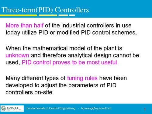
Gd ( s )
where the time constant d of the controller is much smaller than the time constants of the process to be controlled and so it may be neglected to be approximated to Gd(s) = KDs. If we set KD = 0 (i.e., no derivative action), then we have the proportional plus integral (PI) controller
R(s)
E ( s)
KP
U c ( s)
Plant
Y ( s)
Fundamentals of Control Engineering - hp.wang@
Three-term(PID) Controllers
Ziegler-Nichols Rules – Second method:
Three-term(PID) Controllers
Ziegler-Nichols Rules – First method:
Table I
Type of Controller
KP
TI
TD
0 0
0.5L
P
T L T 0.9 L T 1.2 L
PI
L 0.3
PID
2L
Fundamentals of Control Engineering - hp.wang@
Hale Waihona Puke Three-term(PID) Controllers
Ziegler-Nichols Rules – Comments:
外文翻译PID

PID控制PID Control当今的闭环自动控制技术都是基于反馈的概念以减少不确定性。
反馈理论的要素包括三个部分:测量、比较和执行。
测量关键的是被控变量的实际值,与期望值相比较,用这个偏差来纠正系统的响应,执行调节控制。
在工程实际中,应用最为广泛的调节器控制规律为比例、积分、微分控制,简称PID控制,又称PID调节。
The current closed loop automatic control technology is based on the concept of feedback in order to reduce the uncertainty. The elements of the feedback theory include three parts: measurement, comparison, and execution. The key point of measurement which means the actual value of the controlled variable, compared with the expected value, using this deviation to correct the system response, and to execute control adjustment. In engineering practice, the most widely used rules of regulator control are proportional, integral, and differential control, referred to as PID control, also known as PID regulation.PID控制器(比例-积分-微分控制器)是一个在工业控制应用中常见的反馈回路部件,由比例单元P、积分单元I和微分单元D组成。
lsf参数

lsf参数
-b hosts:指定作业的宿主机列表。
这个参数允许用户指定哪些机器可以运行作业。
例如,-b hostA,hostB 表示作业可以在 hostA 和 hostB 上运行。
-c cpus:指定作业所需的CPU数量。
这对于并行计算任务非常重要,因为它告诉LSF 作业需要多少CPU资源。
-g group_name:指定作业所属的用户组。
这可以帮助用户组织和管理作业,特别是当多个用户共享同一套LSF系统时。
-M memory:指定作业所需的内存量。
这对于限制作业的资源使用非常有用,可以避免因为内存不足而导致的问题。
-n number:指定作业的任务数量。
对于并行作业,这通常表示要同时运行的任务数。
-o output_file:指定作业的标准输出文件。
默认情况下,输出会被发送到用户的终端或电子邮件,但通过这个参数,用户可以将输出重定向到指定的文件。
-q queue_name:指定作业应提交的队列。
这允许用户选择作业在系统中的优先级和处理顺序。
-R usage:指定作业的资源需求,包括CPU、内存等。
这是一个更通用的方式来定义作业的资源需求。
-W wallclock:指定作业的最大运行时间。
如果作业在指定时间内没有完成,LSF将终止它。
以上只是一些常见的LSF参数示例,LSF提供了丰富的配置选项和参数,可以根据具体的计算需求进行详细的配置。
时滞光电跟踪系统鲁棒内模PID控制器设计
时滞光电跟踪系统鲁棒内模PID控制器设计赵志诚;刘志远;张井岗【摘要】针对时滞光电跟踪提出了一种内模PID(IMC-PID)控制器设计与参数整定的解析方法.首先建立了系统的一阶时滞积分(FODI)模型,并用二阶加时滞(SOPDT)模型进行逼近,然后利用一阶Taylor表达式代替系统模型中的时滞项,导出了控制器参数的整定规则.特别是为了保证系统的鲁棒性,可以根据最大灵敏度解析计算内模PID控制器的可调参数λ_n.仿真结果表明,与常规方法相比,所提方法不仅提供了较好的设定值跟踪和扰动抑制特性,而且对于系统参数摄动具有更好的鲁棒性.另外,实验结果也证实了该方法能够提高系统跟踪性能和跟踪精度.【期刊名称】《光电工程》【年(卷),期】2010(037)001【总页数】7页(P30-36)【关键词】内模PID;光电跟踪系统;时滞系统【作者】赵志诚;刘志远;张井岗【作者单位】哈尔滨工业大学控制科学与工程系,哈尔滨,150001;太原科技大学自动化系,太原,030024;哈尔滨工业大学控制科学与工程系,哈尔滨,150001;太原科技大学自动化系,太原,030024【正文语种】中文【中图分类】V5560 IntroductionOpto-electronic tracking system is a complex equipment which mainly includes photoelectric detection,signal processing, control systems, precision machinery and other parts. It is widely applied in the filed of civilian and military industry such as NC machine tools, astronomical observation, shooting range measurement, weapons control, and flight simulators etc[1]. For opto-electronic tracking system, a good servo performance, such as high-accuracy, high-speed, non-overshoot and no vibration, is necessary [2]. Furthermore, in order to keep stability for parameter perturbation system, a high robustness is also very important.In other words, it is expected to achieve both performance and robustness in opto-electronic tracking system. However, considering the disturbance and uncertainty in the system, the conventional PID control is difficult to meet the requirement of the control performance effectively.So, based on the PID control, many improved PID type control schemes are researched in [1][3][4],respectively. A multi-mode control algorithm was proposed in [3]. The algorithm is expressed as follows: if the error is large, the saturation control is adopted; if the error is medium, the square root control is adopted; and if the error is small, the PID control is adopted. Paper [4]proposed a fuzzy-PID control approach, which could shorten the transient time, reduce the overshoot and improve the tracking accuracy and robustness of control system. Paper[1]proposed a single neuron fuzzy PID control method. Thus the trackingsystem not only has the capability of learning and self-adaptation, but also has better dynamic performance and steady-state performance than that of PID control. But in the above-mentioned schemes, the measurement time-delay of image tracker is not considered.To deal with the measurement time-delay, various advanced control approaches are presented. Paper [5]proposed an adaptive prediction and compensation method, which applied LMS algorithm and an adaptive filter with transverse structure to delay prediction compensation. The simulation results demonstrated the effectiveness of the method. Paper [6]introduced the method of predictive filtering in opto-electronic tracking system. Paper [7]adopted a state prediction and estimation method based on robust H∞ filter for opto-electronic tracking system.The experimental results show that the proposed method has high accuracy and good robustness. Whereas, the predictive filtering method needs complex calculation, and it easily causes the arithmetic to diverge.To find a simple design method of the PID type controller with a significant performance improvement has become an important research issue for control engineers. Because of the simplicity and improved performance of the IMC-based tuning rules, the analytically derived IMC-PID tuning methods have attracted the attention of industrial users [8]. The IMC-PID tuning rule has only one user-defined tuning parameter, which is directly related to the closed-loop performance and robustness of the system. The PID controller design has been discussed extensively in the literature for first-order plus delay time and second-order plus delay timestable/unstable process[8-10]. But the design of a simple and robust controller with improved performance has not yet been fully achieved. This paper focuses on the design of IMC-PID controller for an opto-electronic tracking system with time-delay. The system can be represented by a first-order delayed integrating (FODI)model. According to the principle of IMC, an analytical design approach of PID controller is proposed. Then, the tuning method of the controller parameter is given. Moreover, the maximum sensitivity can be applied to guarantee the robustness of the system. The simulation and experimental results show that this scheme is easy to be realized and has better performance than the conventional approach.1 Design of IMC-PID Controller for Time-delay SystemThe block diagram of IMC system is shown in Fig.1, where Q(s)is the internal model controller, G(s)is the process, M(s)is the model, and R(s),Y(s), D(s)is the set point, output and external disturbance of the system respectively. According to the design procedure for IMC system, the model is factorized asWhere M-(s) and M+(s)are the portions of the model inverted and not inverted, respectively. M+(s)is usually a non-minimum phase and contains delay time and/or right half plane zeros of M(s), while M-(s)is stable and of minimum phase with no predictors. The IMC controller Q(s)takes the formWhere f(s)is a user specified low-pass filter and usually chosen asWhere r is sufficiently large in order to guarantee that the IMC controller Q(s)is proper. Also, λ is the time constant, determined by the expected system performance. A smaller λ provides faster closed-loop response, while a l arger λ is also less sensitive to model mismatches.Fig.1 Block diagram of IMCFig.2 Equivalent block diagram of IMCIMC structure in Fig.1 can be reduced to the equivalent classic feedback structure shown in Fig.2. Gc(s)is a feedback controller. The relation between the feedback controller Gc(s)and the internal model controller Q(s)can be expressed as follows:System dynamics are often approximated by low order transfer function models for ease in controller design.The dynamics of a large number of industrial controlled objects can be represented by FOPDT and SOPDT transfer function models of the forms:The IMC filter structure exploited here is given asSo, the IMC controller can be obtained, and the corresponding feedback controller isIn order to make the resulting controller in Eq.(9)has a PID controller structure, the time-delay term is approximated by the simple first orderTaylor expansion.Let the forms of the PI and PID controllers beWhere Kp, Ti and Td are the proportional gain, the integral time constant and the derivative time constant,respectively. Table 1 shows the IMC-based PI/PID controller settings for the FOPDT and SOPDT models, where λn = λ/θ.Table 1 Settings of the controller for FOPDT and SOPDT modelsM(s)Kp Ti Td τ τ K s τs 1 e+-θK(λ+θ)=θ(λ+)k τ n 1-θ e s τs+2 22 K s ξτ+1K(λξτ 2ξτ 2+2ξτ θ)=θ(λ+)Kn 1ξ τ22 Design of IMC-PID Controller for Opto-electronic Tracking System2.1 Model of Opto-electronic Tracking SystemUsually, a high accuracy opto-electronic tracking system is a speed-position control system constituted of two closed-loops, which is annexed a position loop on the base of the speed governing system. The configuration of opto-electronic tracking system is shown in Fig.3. TheTV/IR tracker includes cameras and signal processing circuit. The module picks and separates the targets in visible-field according to the standard phase alternating line,and provides the target coordinates of current point. Taking into account the image processing, the measurement time-delay can not be ignored. So the image tracker can be depicted by a proportion plus time-delay model. The speed controller adopts proportion-integral (PI)algorithm, and the speed feedback device is an opto-electronicencoder. In practice the speed control loop can be approximated to a first-order inertia unit due to the high crossover frequency. The reduction ratio of the reducer is i: 1. The transfer function from the angular velocity of the motor to the output of the system can be represented by an integrator, and the integral time is i. So the dynamic structure of opto-electronic tracking system is shown in Fig.4. Namely, the position tracking system can be represented by a first-order delayed integrating (FODI)model:Fig.3 Block diagram of opto-electronic tracking systemFig.4 Dynamic structure of opto-electronic tracking system2.2 Design of IMC-PID controllerConsider the FODIP model of the opto-electronic tracking system as Eq.(13). It can be approximated as SOPDT model, and becomesWhere φ is an arbitrary constant with a sufficiently large value. Thus, the IMC-PID controller is the same as that for the SOPDT. According to the PID tuning rules listed in Table 1, the parameters of the PID are given asWhere λn = λ/θ.3 Tuning of the Parameter of the ControllerGain and phase margins are two well known measures of robustness and simple analytical formulas to tune PI/PID controller for stable/unstable FOPDT and SOPDT models to meet user defined gain and phase margins have been proposed. However, the gain and phase margin specificationsgive poor results for systems with unusual frequency response curve and may fail to give reasonable bounds on the sensitivity functions [11]. The maximum sensitivity (Ms)is the inverse of the shortest distance from the Nyquist curve of the open loop transfer function to the critical point (-1, j0), and is defined asMs measures the closeness of the Nyquist curve from the critical point at all frequencies and not just the two frequencies as associated with gain and phase margins, so it can serve as a better measure of system robustness. A small value of Ms indicates that the stability margin of the control system is large. Typical values of Ms are in the range of 1.2∼2.0.A first order Pade approximation is used to replace the delay term of the loop transfer function, and the sensitivity function can be written. For 1/ Ms to be the minimum distance of the Nyquist curve from the critical point, the Nyquist curve of the loop transfer function should touch the circle with centre (-1, j0)and radius 1/ Ms.According to the repeated roots condition of the sensitivity function, the relation between the adjustable parameter λn of IMC-PID controller and the maximum sensitivity Ms can be get [11]Where, λn = λ/θ. The λn can be obtained by solving (17)f or various values of Ms.4 Simulation and Experiment ResultsTo demonstrate the effectiveness of the proposed method, simulation studies are carried out. Suppose the model for an opto-electronic trackingsystem is represented as the following FODI model, which can be approximated by the SOPDT mode asThe maximum sensitivity Ms = 1.2 is chosen. Hence, the adjustable parameter λn of IMC-PID controller can be calculated via Eq.(17), and the parameters of the controller can be tuned via Eq.(15). In addition, the parameters of a conventional PID controller can be found by using the Z-N method. The system is simulated with a unit step reference at t= 0 and a step output disturbance with value of 0.2 at t = 2.When the model is accurate, the simulation result is shown in Fig.5. For the conventional method, although the response is faster than the proposed method, but the response has a large overshoot. Hence, the proposed method not only provides a better set-point tracking, but also has a steadier disturbance rejection response.Fig.5 Step response with a nominal modelFig.6 Step response with +50%mismatches in gainFig.7 Step response with +50%mismatches in time constantFig.8 Step response with +100%mismatches in delay timeThe robustness of the controller is evaluated by inserting a perturbation uncertainty of +50% in the static gain K, the time constant T and +100% in the delay time θ to yield the model mismatch, respectively. The simulation results for the proposed and conventional tuning rules are shown in Fig.6∼Fig. 8. When all three parameters vary simultaneously, the response shown in Fig.9 exhibits the worst-case model mismatchIn addition, the proposed method was applied to an opto-electronic tracking system to track an air target and the effect was compared with conventional approach. The target flies at an altitude of 1 000 meters with v=150 m/s. The range of azimuth and elevation is from 1 439 mil to 570 mil and from 542 mil to 1 385 mil,respectively. During this process, the maximum angular velocity and acceleration of azimuth tracking is 60 °/s and 80 °/s2, respectively.Correspondingly, the maximum angular velocity and acceleration of elevation tracking is 7.5 °/s and 7 °/s2,respectively. The sampling cycle of the control system is 20 ms. The tracking error curves of the proposed method are shown in Fig.10. Obviously, the error variety is steady and undistinguishable. Fig.11, which is got from conventional method, shows that the error variety is obvious and the tracking error is larger. So the conclusion can be drawn that the proposed method can bring better tracking property and higher accuracy.Fig.9 Step response with mismatches in all parameters simultaneously Fig.10 Tracking error with the proposed methodFig.11 Tracking error with the conventional method5 ConclusionAiming at an opto-electronic tracking system with time-delay, an analytical design method and parameters tuning approach of IMC-PID controller is presented. Firstly, a FODI model for the system is built, and the model can be approximated by the SOPDT mode. On the basis of the simple first-order Taylor approximant for the time-delay term, the tuning rules of the controller parameter are provided. Especially the adjustable parameter λnof IMC-PID controller can be calculated by choosing the maximum sensitivity to guarantee robustness of the system. The simulation results show that the proposed method not only provides a better dynamic performance of both the command tracking and disturbance rejection, but also is more robust against the parameters perturbation.In addition, the experimental result demonstrates the method can bring better tracking property and higher accuracy.References:[1]王婵娟,王强,傅承毓. 单神经元模糊PID控制在光电跟踪系统中的应用 [J]. 光电工程,2006,33(2):33-36.WANG Chan-juan,WANG Qiang,FU Cheng-yu. Single neuron fuzzy PID control application in photoelectric tracking system[J]Opto-Electronic Engineering,2006,33(2):33-36.[2]Fujimoto H,Hori Y,Kawamura A. Prefect tracking control based on multirate feedforword control with generalized sampling periods [J]. IEEE Transactions on Industrial Electronics(S0278-0046),2001,48(3):636-644.[3]冯培业,董宁,张宇河. 天地景投影伺服系统控制算法的改进 [J]. 北京理工大学学报,2002,22(3):351-354.FENG Pei-ye,DONG Ning,ZHANG Yu-he. Improvement of the control algorithm of a servo system for background projection system [J]. Transactions of Beijing Institute of Technology,2002,22(3):351-354.[4]侯宏录,周德云,王伟. 模糊PID 控制在光电跟踪控制系统中的应用 [J]. 光电工程,2006,33(5):12-16.HOU Hong-lu,ZHOU De-yun,WANG Wei. Application of fuzzy-PID control in system of photo-electric tracking [J].Opto-Electronic Engineering,2006,33(5):12-16.[5]王连明,葛文奇,李杰. 跟踪系统中跟踪延迟的自适应预测补偿方法 [J]. 光电工程,2002,29(4):13-16.WANG Lian-ming,GE Wen-qi,LI Jie. Adaptive prediction and compensation method for delay of tracker in tracking system[J]. Opto-Electronic Engineering,2002,29(4):13-16.[6]杨秀华,吉桐伯,陈娟. 预测滤波技术在光电跟踪系统的应用 [J]. 电光与控制,2003,10(3):11-15.YANG Xiu-hua,JI Tong-bo,CHEN Juan. Applicationof predicting filter in electro-optical tracking system [J]. Electronics Optics &Control,2003,10(3):11-15.[7]许波,姬伟. 基于鲁棒H∞滤波的光电跟踪机动目标状态预测估计[J]. 光电工程,2008,35(1):5-10.XU Bo,JI Wei. State prediction and estimation foropto-electronic tracking maneuvering targets based on robust H∞ Filter [J]Opto-Electronic Engineering,2008,35(1):5-10.[8]Shamsuzzoha M,Moonyong Lee. Design of advanced PID controller for enhanced disturbance rejection of second-order processes with time delay [J]. American Institute of Chemical Engineers(S0001-1541),2008,54(6):1526-1536.[9]Raymond Gorez. New design relations for 2-DOF PID-like control systems [J]. Automatica(S0005-1098),2003,39(5):901-908.[10]Rames C Panda,Cheng-Ching Yu,Hsiao-Ping Huang. PID tuning rules for SOPDT systems:review and some new results [J].ISA Transactions(S0019-0578),2004,43(2):283-295.[11]Ahmad Ali,Somanath Majhi. PI/PID controller design based on IMC and percentage overshoot specification to controller set-point change [J].ISA Transactions(S0019-0578),2009,48(1):10-15.。
pidtuningguide
4-5 Open Loop Tuning Procedure 6-7 Reference List of Common Controllers 8 8 INTUNE v5 & MANTRA Descriptions ControlSoft Contact Information
E-MAIL info@ WEB PHONE 440-443-3900; FAX 440-443-0249 5387 Avion Park Drive, Highland Heights OH 44143
OMRON PID BLOCKS
PID Block P Gain (Gain * 1) I Time Constant (Sec * 10) D Time Constant (Sec * 10)
SIEMENS PID BLOCKS
TI PID Block P Gain (Gain * 1) I Time Constant (Min * 1) D Time Constant (Min * 1) S7 controller C non-interacting P Gain (Gain * 1) I Time Constant (Sec * 1) D Time Constant (Sec * 1)
DESCRIPTION OF PID UNITS
Proportional Term is the amount added to the output based on the
current error. Proportional Gain is a Multiplier. If the error is 10 and the Gain is .8, then the output will move 8%. Proportional Band is a Divider as a percentage. If the error is 10 and the Band is 125%, then output is (10*(100/125))=8%. Conversion between P-Gain and P-Band: P-Band = 100/P-Gain Integral Term is the amount added to the output based on the sum of the error. Time Constant is the time for one full repeat of P-Term. If the P-Term is 8% and the Time Constant is 10 seconds, then the output will ramp up 8% every 10 seconds. Reset Rate is amount the output will move in one second. If the P-Term is 8% and the Reset Rate is .1 repeat/sec, then the output will move .1*8 every second and take 10 seconds for the full repeat of the P-Term of 8%. Integral Gain is the same as the Reset Rate multiplied by the P-Gain. Conversion between Time and Reset Rate: Reset Rate = 1/ Time Constant I-Gain = (1/Time Constant)*P-Gain Derivative Term is the amount subtracted from the output based on the rate of change of the error. Time Constant is the amount of time the controller will look forward. Derivative Gain is the amount of time the controller looks forward multiplied by the P-Gain.
linux 最小pid分配规则
在Linux操作系统中,进程ID(PID)是用于唯一标识正在运行的进程的整数值。
进程ID从2开始,因为进程ID 0保留给调度进程(通常是内核线程),进程ID 1保留给init进程(或其替代者,如systemd)。
Linux中的进程ID分配规则如下:
PID 0 和PID 1:P ID 0(通常称为"swapper"或"init")是内核线程,而PID 1 是系统初始化进程(例如init、systemd等)。
这两个PID保留,并不分配给用户进程。
PID 2 到PID 32767:这些PID范围用于分配用户进程。
新创建的进程会被分配最小未使用的PID。
回收释放的PID:当进程终止(或被杀死)时,其所占用的PID会被释放,以便在需要时重新分配给新进程。
这意味着,随着进程的创建和终止,PID会被动态地回收和分配。
需要注意的是,Linux的PID分配是按需分配的,即未使用的最小PID会被分配给新的进程。
这是为了确保分配的PID在给定时间段内尽可能小,以避免PID的过早耗尽。
PID的最大值是32767,这是由内核限制决定的。
一旦分配的PID达到最大值,系统将无法再创建新的进程。
在现代Linux系统中,PID分配通常会非常高效,因为内核会维护一个进程表和PID位图,以追踪已分配和可用的PID。
这确保了进程的唯一性和可管理性。
如果您需要查看当前系统上运行的进程以及它们的PID,可以使用ps命令或top命令。
linux分配pid策略
linux分配pid策略
在Linux系统中,分配PID(进程标识符)的策略是通过进程调度算法来确定的。
Linux中采用的是动态分配的PID策略。
在Linux系统中,PID是一个唯一的整数值,用于标识每个正在运行的进程。
PID从2开始分配,以避免与操作系统的一些特殊进程(如init进程)冲突。
在动态分配PID的策略中,当一个进程创建时,操作系统会选择一个未使用的PID分配给该进程。
操作系统会维护一个进程表来记录当前正在运行的进程以及它们的PID。
每当一个进程终止时,它的PID就会被回收,可以再次分配给新创建的进程。
在Linux中,PID是有限的,最大值可以通过/proc/sys/kernel/pid_max文件来确定。
当达到这个最大值时,操作系统将无法再分配新的PID,从而不允许创建新的进程。
除了PID的动态分配策略外,Linux还采用了一些其他策略来提高PID的有效利用。
例如,操作系统会使用PID回收机制来重新利用已经终止的进程的PID,以避免浪费。
此外,操作系统还会使用PID的位图来跟踪已分配的PID,以及使用槽位来存储已分配的PID的状态信息。
总的来说,Linux在分配PID时采用动态分配策略,将未使用的PID分配给新创建的进程,并通过回收机制和位图来提高PID的有效利用。
linux pid号使用规则
linux pid号使用规则Linux PID (Process ID) usage rules are an essential aspect of managing and monitoring processes running on a Linux system. Understanding these rules is crucial for system administrators, developers, and users to effectively manage and troubleshoot processes.In Linux, each process is assigned a unique PID, which serves as an identifier for that particular process. PIDs are crucial for various system operations such as process management, signal handling, and resource allocation. The PID space in Linux is finite, and the maximum value depends on the system architecture and configuration.PIDs are assigned sequentially, starting from 1, and can go up to the maximum allowed value. When a process terminates, its PID becomes available for reuse by a new process. PIDs are not recycled immediately to avoid any confusion or conflicts with existing processes that might still be referencing the old PID.The PID 1 is typically reserved for the init process, which is the first process started by the Linux kernel during system boot. Init is responsible for starting and managing other processes, serving as the parent process for most user-space processes. It is crucial for the system's stability and functionality.Processes in Linux are organized in a hierarchical structure, with each process having a parent process and possibly multiple child processes. When a process is created, it inherits the PID of its parent process. This hierarchical relationship allows for easy process management and tracking.PID numbers are unique within a given Linux system, meaning that no two processes can have the same PID at any given time. This uniqueness is crucial for identifying and distinguishing between different processes running on the system. It allows for targeted process management, such as sending signals or terminating specific processes.To ensure efficient process management, Linux provides various tools and commands that utilize PIDs. For example, the 'ps' command can be used to list running processes along with their corresponding PIDs. The 'kill' command allows sending signals to processes based on their PIDs, enabling actions like terminating or restarting processes.In conclusion, Linux PID usage rules are vital for managing and monitoring processes on a Linux system. PIDs are unique identifiers assigned to each process, allowing for efficient process management, signal handling, and resource allocation. Understanding these rules enables system administrators, developers, and users to effectively manage and troubleshoot processes, ensuring the stability and functionality of the Linux system.。
- 1、下载文档前请自行甄别文档内容的完整性,平台不提供额外的编辑、内容补充、找答案等附加服务。
- 2、"仅部分预览"的文档,不可在线预览部分如存在完整性等问题,可反馈申请退款(可完整预览的文档不适用该条件!)。
- 3、如文档侵犯您的权益,请联系客服反馈,我们会尽快为您处理(人工客服工作时间:9:00-18:30)。
B = B / w n . If we can find the relations between z , B
and the normalized control parameters, and represent
K,
Ti , Td and b as functions of z and B , these functions
controller output, set point, system output, controller gain, set-point weighting, integral time, derivative time, and error, respectively. Notice that the controller parameters K , b , Ti and Td must be positive constants. Denote the loop transfer function of the closed-loop system as Gl ( s ) and define M s as
This paper presents PID tuning rules for second systems. These tuning rules are derived by optimizing the integrated absolute errors of set point and load disturbance responses under robustness and bandwidth constrains. For deriving the tuning formulas, PID controllers for normalized systems were designed. The relationship between the controller parameters, the parameters that characterize the system dynamics and the normalized gain crossover frequency are determined and the tuning formulas are then derived. Simulation examples and experimental results are provided to demonstrate the effectiveness of these tuning rules. model of systems and the design method of PID controller are described. Section 3 presents the way to derive the tuning rules. Simulation and experimental results are given in Section 4. Finally, conclusions are drawn in Section 5.
ed denote the error caused by a unit step
J = Ú es (t ) dt + Ú ed (t ) dt .
0 0 • •ຫໍສະໝຸດ disturbance at the system input, respectively. Define the performance index as
2. MODEL AND DESIGN METHOD
Consider the following system
2 K sw n (1) 2 s2 + 2zw n s + w n where K s is the static gain, w n is the undamped natural frequency and z is the damping ratio. For over-damped systems ( z > 1), the models in (1) can be rewritten as Ks (2) Gs = (1 + sT )(1 + sT1 )
PID Tuning Rules for Second Order Systems
Jing-Chung Shen Huann-Keng Chiang*
Department of Automation Engineering National Huwei Institute of Technology Huwei, Yunlin, Taiwan Email: jcshen@.tw *Department of Electrical Engineering National Yunlin University of Science and Technology Toulou, Yunlin, Taiwan ABSTRACT
where
1/ T = w n (z - z 2 - 1) , 1/ T1 = w n (z + z 2 - 1) . (3)
When T1 < 10T (z > 1.74) , the models in (2) can be well approximated by
Ks . (1 + sT ) In this paper, the systems with z £ 2 are considered. Gso =
Gs =
Key Words: bandwidth, PID controllers, tuning rules,
second order system.
1. INTRODUCTION
PID controller is the most common control algorithm and is widely used. There are a lot of tuning rules for PID controllers [1-19]. Most of the tuning rules are derived for process control and are derived under idealize assumptions, such as infinite bandwidth. In fact, in most applications, the measurement noise, the range of manipulated variable and the sample rate of the system limit the closed-loop bandwidth. In this paper, PID tuning rules for second order systems are derived. For deriving the tuning rules, PID controllers for some normalized second order systems are designed. These PID controllers are designed by optimizing the integrated absolute errors (IAE) of set point and load disturbance responses under constraints on robustness and crossover frequency (the frequency where the loop gain equals one). Note that the closed-loop bandwidth can be approximated by the crossover frequency [20]. Therefore, the PID controllers are designed under bandwidth constrain. When the PID controllers for normalized systems are designed, the curve fitting technique is used to derive simple formulas that describe the relationships among normalized PID controller parameters, parameters that characterize the system dynamics and the normalized crossover frequency. Once these formulas are derived, they can be used to tune the PID controllers. Simulation examples and experimental results show that these formulas give satisfactory results. This paper is organized as follows: In Section 2, the
M s = max
w
1 . 1 + Gl ( jw )
M s is the inverse of the shortest distance from the Nyquist
curve of the loop transfer function to the critical point –1 and is a measure of stability robustness. Typical value of M s is in the range from 1.4 to 2.0 and the standard value is 2.0 [10]. Let es denote the error caused by a unit step set-point change and
