ER3G-T3中文资料
T3ster中文手册

明导公司 Mechanical Analysis 部门为结构设计和热特性市场提 供测试与仿真解决方案与咨询服务,在该领域服务各行业客户 22 年。 Mechanical Analysis 部门在全球四十多个国家和地区配备有销售 和技术办事处或代理,服务当地市场。在中国的上海、北京和深 圳三地均设有办事处。
96% 的客户乐意向同 行推荐我们的产品
Mechanical Analysis 的产品,不仅得到用户的高度评价,也得到 了行业的一致公认: 荣获由英国首相 Tony Blair 授予的优秀商业企业奖 T3Ster 产品研发负责人荣获匈牙利最高技术荣誉奖,受到匈 牙利国会议员接见 工业行业著名传媒”Design News”网友和资深编辑共同评选结 果,我们的同步 CFD 获得最佳新产品奖 同步 CFD 帮助美国堪萨斯州的高中学生获得 “真实设计挑战” 赛全国冠军 EDN 杂志中国版评选同步 CFD:创新产品奖
为什么选择 T3Ster 热测试仪?
高达 1μs 的瞬态测量精度 ■ T3ster 配 置 软 件 采 用 的 NID(Network identification by deconvolution ,反卷积网络计算 ) 方 法,要获得准确的计算结果,其所采 集的实验数据必须是非常准确且连 续的瞬态数据。 ■比如,在LED封装测试当中,如果 瞬态变化的最初 1ms 时间的瞬态温 度变化没有被采集到, 那么最终测试 出的热阻将被低估10%-15%, ■T3ster测试仪采集瞬态数据的精度 高达1μs, 可以完美地捕捉到每一个 温度的瞬态变化。 保证了分析软件分 析结果的准备性。
市场上最高的灵敏度 ■在测量封装的结温时, 高的信噪比 可以充许非常精细的测量。T3ster提 供了市场您能见到的测试仪器当中 最高的灵敏度, 无需封装有太高的发 热功耗,T3ster可以通过其高精度的 微分输入放大器获取准确的温度结 果。温度分辨率高达0.01摄氏度。
NetNumenT传输网管

服务器安装需要硬盘空间约为5.3G;典型安装时,所需要 的空间是5.7G。但考虑到服务器端的日志信息、数据备份信 息较多,所以,在安装服务器的计算机上,必须预留2G以上的剩 余磁盘空间。综上所述,推荐为T3安装预留10G空间。
T31网管安装
2.T31网管安装指导
1)典型安装
l)上图中输入服务器的IP,数据库主机IP,Server Session Id单 击, 单击<上一步>按钮返回上一步操作;单击<取消>按钮退 出安装;<下一步>按钮,弹出正在安装对话框,对话框中显 示安装进度条 。
NE NE
NE NE
网元管理层分别提供单网元、网元级、网络级管理功能
T3系列产品介绍
T3是一个系列化的产品族,其全称为NetNumenTM T3x, 其中的x按产品应用场景分别为0、1、2……。
T30----LCT T31----EMS T32----NMS T3……
2.T31网管安装指导
1)典型安装
e)在上图所示的软件许可协议对话框中,单击<上一步>按钮返 回上一步操作;单击<取消>按钮退出安装;选择接受许可协 议条款,单击<下一步>弹出输入产品许可码T3对话框,如下 图所示。
T31网管安装
2.T31网管安装指导
1)典型安装
f)在上图所示的输入产品许可协议码对话框中输入序列号[l1] ,单 击<上一步>按钮返回上一步操作;单击<取消>按钮退出安 装;单击<下一步>弹出选择产品类型对话框。
SN74S283N3中文资料
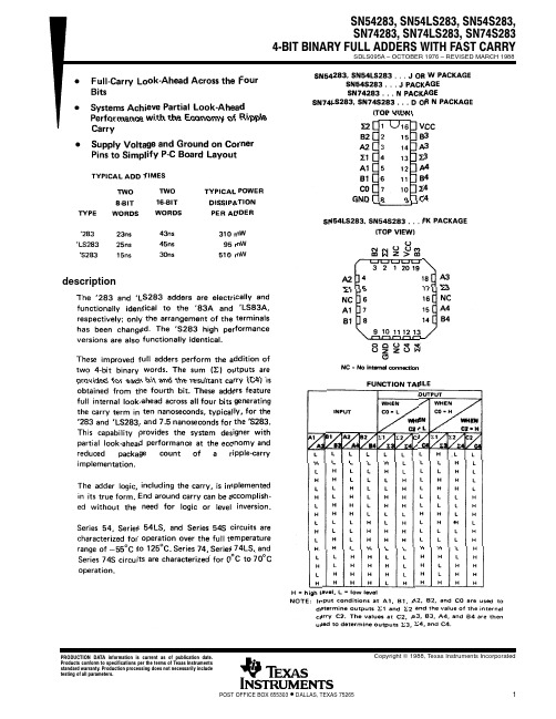
descriptionCopyright 1988, Texas Instruments Incorporated PRODUCTION DATA information is current as of publication date.PACKAGING INFORMATIONOrderable Device Status(1)PackageType PackageDrawingPins PackageQtyEco Plan(2)Lead/Ball Finish MSL Peak Temp(3)76043012A ACTIVE LCCC FK201TBD Call TI Level-NC-NC-NC7604301EA ACTIVE CDIP J161TBD Call TI Level-NC-NC-NC7604301FA ACTIVE CFP W161TBD Call TI Level-NC-NC-NC JM38510/31202B2A ACTIVE LCCC FK201TBD Call TI Level-NC-NC-NC JM38510/31202BEA ACTIVE CDIP J161TBD Call TI Level-NC-NC-NC JM38510/31202BFA ACTIVE CFP W161TBD Call TI Level-NC-NC-NC SN54LS283J ACTIVE CDIP J161TBD Call TI Level-NC-NC-NCSN54S283J ACTIVE CDIP J161TBD Call TI Level-NC-NC-NCSN74283N OBSOLETE PDIP N16TBD Call TI Call TISN74LS283D ACTIVE SOIC D1640Green(RoHS&no Sb/Br)CU NIPDAU Level-1-260C-UNLIMSN74LS283DE4ACTIVE SOIC D1640Green(RoHS&no Sb/Br)CU NIPDAU Level-1-260C-UNLIMSN74LS283DR ACTIVE SOIC D162500Green(RoHS&no Sb/Br)CU NIPDAU Level-1-260C-UNLIMSN74LS283DRE4ACTIVE SOIC D162500Green(RoHS&no Sb/Br)CU NIPDAU Level-1-260C-UNLIMSN74LS283N ACTIVE PDIP N1625Pb-Free(RoHS)CU NIPDAU Level-NC-NC-NC SN74LS283N3OBSOLETE PDIP N16TBD Call TI Call TISN74LS283NE4ACTIVE PDIP N1625Pb-Free(RoHS)CU NIPDAU Level-NC-NC-NCSN74LS283NSR ACTIVE SO NS162000Green(RoHS&no Sb/Br)CU NIPDAU Level-1-260C-UNLIMSN74LS283NSRE4ACTIVE SO NS162000Green(RoHS&no Sb/Br)CU NIPDAU Level-1-260C-UNLIM SN74S283D OBSOLETE SOIC D16TBD Call TI Call TISN74S283N ACTIVE PDIP N1625Pb-Free(RoHS)CU NIPDAU Level-NC-NC-NC SN74S283N3OBSOLETE PDIP N16TBD Call TI Call TISN74S283NE4ACTIVE PDIP N1625Pb-Free(RoHS)CU NIPDAU Level-NC-NC-NC SNJ54LS283FK ACTIVE LCCC FK201TBD Call TI Level-NC-NC-NC SNJ54LS283J ACTIVE CDIP J161TBD Call TI Level-NC-NC-NC SNJ54LS283W ACTIVE CFP W161TBD Call TI Level-NC-NC-NC SNJ54S283FK ACTIVE LCCC FK201TBD Call TI Level-NC-NC-NC SNJ54S283J ACTIVE CDIP J161TBD Call TI Level-NC-NC-NC SNJ54S283W ACTIVE CFP W161TBD Call TI Level-NC-NC-NC (1)The marketing status values are defined as follows:ACTIVE:Product device recommended for new designs.LIFEBUY:TI has announced that the device will be discontinued,and a lifetime-buy period is in effect.NRND:Not recommended for new designs.Device is in production to support existing customers,but TI does not recommend using this part in a new design.PREVIEW:Device has been announced but is not in production.Samples may or may not be available.OBSOLETE:TI has discontinued the production of the device.(2)Eco Plan-The planned eco-friendly classification:Pb-Free(RoHS)or Green(RoHS&no Sb/Br)-please check/productcontent for the latest availability information and additional product content details.TBD:The Pb-Free/Green conversion plan has not been defined.Pb-Free(RoHS):TI's terms"Lead-Free"or"Pb-Free"mean semiconductor products that are compatible with the current RoHS requirements for all6substances,including the requirement that lead not exceed0.1%by weight in homogeneous materials.Where designed to be soldered at high temperatures,TI Pb-Free products are suitable for use in specified lead-free processes.Green(RoHS&no Sb/Br):TI defines"Green"to mean Pb-Free(RoHS compatible),and free of Bromine(Br)and Antimony(Sb)based flame retardants(Br or Sb do not exceed0.1%by weight in homogeneous material)(3)MSL,Peak Temp.--The Moisture Sensitivity Level rating according to the JEDEC industry standard classifications,and peak solder temperature.Important Information and Disclaimer:The information provided on this page represents TI's knowledge and belief as of the date that it is provided.TI bases its knowledge and belief on information provided by third parties,and makes no representation or warranty as to the accuracy of such information.Efforts are underway to better integrate information from third parties.TI has taken and continues to take reasonable steps to provide representative and accurate information but may not have conducted destructive testing or chemical analysis on incoming materials and chemicals.TI and TI suppliers consider certain information to be proprietary,and thus CAS numbers and other limited information may not be available for release.In no event shall TI's liability arising out of such information exceed the total purchase price of the TI part(s)at issue in this document sold by TI to Customer on an annual basis.IMPORTANT NOTICETexas Instruments Incorporated and its subsidiaries (TI) reserve the right to make corrections, modifications, enhancements, improvements, and other changes to its products and services at any time and to discontinue any product or service without notice. Customers should obtain the latest relevant information before placing orders and should verify that such information is current and complete. All products are sold subject to TI’s terms and conditions of sale supplied at the time of order acknowledgment.TI warrants performance of its hardware products to the specifications applicable at the time of sale in accordance with TI’s standard warranty. T esting and other quality control techniques are used to the extent TI deems necessary to support this warranty. Except where mandated by government requirements, testing of all parameters of each product is not necessarily performed.TI assumes no liability for applications assistance or customer product design. Customers are responsible for their products and applications using TI components. T o minimize the risks associated with customer products and applications, customers should provide adequate design and operating safeguards.TI does not warrant or represent that any license, either express or implied, is granted under any TI patent right, copyright, mask work right, or other TI intellectual property right relating to any combination, machine, or process in which TI products or services are used. Information published by TI regarding third-party products or services does not constitute a license from TI to use such products or services or a warranty or endorsement thereof. Use of such information may require a license from a third party under the patents or other intellectual property of the third party, or a license from TI under the patents or other intellectual property of TI.Reproduction of information in TI data books or data sheets is permissible only if reproduction is without alteration and is accompanied by all associated warranties, conditions, limitations, and notices. Reproduction of this information with alteration is an unfair and deceptive business practice. TI is not responsible or liable for such altered documentation.Resale of TI products or services with statements different from or beyond the parameters stated by TI for that product or service voids all express and any implied warranties for the associated TI product or service and is an unfair and deceptive business practice. TI is not responsible or liable for any such statements. Following are URLs where you can obtain information on other Texas Instruments products and application solutions:Products ApplicationsAmplifiers Audio /audioData Converters Automotive /automotiveDSP Broadband /broadbandInterface Digital Control /digitalcontrolLogic Military /militaryPower Mgmt Optical Networking /opticalnetwork Microcontrollers Security /securityTelephony /telephonyVideo & Imaging /videoWireless /wirelessMailing Address:Texas InstrumentsPost Office Box 655303 Dallas, Texas 75265Copyright 2005, Texas Instruments Incorporated。
欧姆龙变频器3G3MX2 样本

标准规格
● 三相200V级
项目
机型名称(3G3MX2-)
CT kW
VT 适用电机容量
CT HP
VT
CT
200V
额定输出容量
VT
[kVA]
CT 240V
VT
额定输入电压
额定输出电压
CT 额定输出电流[A]
VT
短时间减速时 制动转矩 (%) ( 未连接放电电阻 )
制动电阻电路 *1
再生制动
可连接的 最小电阻值[Ω]
重量[kg]
尺寸(宽×高)[mm]
尺寸(进深)[mm]
*1. BRD使用率为10%。
● 三相400V级
项目
机型名称(3G3MX2-□-Z)
CT kW
VT 适用电机容量
CT HP
VT
CT
380V
额定输出容量
VT
[kVA]
CT 480V
VT
额定输入电压
额定输出电压
CT 额定输出电流[A]
VT
短时间减速时 制动转矩 (%) ( 未连接放电电阻 )
ᔶᇣᎻ
Ϣᴀ݀ৌ*5; N:ൟ Ⳍ↨ˈᆑᑺǃ催ᑺ ሎᇌ㓽ޣ㑺ⱘৠᯊᅲ⦄њᔎⱘࡳ㛑DŽ
Ƶ*0; $ ৠॳሎᇌ
খ᭄㓪䕥ㄝ &; 'ULY H
86%
ᅝܼ䕧ܹ ᅝܼⲥ䕧ߎ
䜡ᅝܼࡳ㛑
> @ ヺড়,62 3/G ,(& 6WRS &DWHJRU\ ᅝܼᷛޚ ⫼᠋䳔∖ ᏠᳯҹԢ៤ᴀ䕏ᵒᅲ⦄Ϣব乥఼ᑊ⫼ⱘ
• 高速变频器通信(Modbus) 无需通信选装件便可进行多址通信 可执行多轴同时运行指令。
• 输出频率 高频模式下最大支持1000Hz • 简易定位功能
LRT-T3使用说明书

三、 输入输出全光电隔离,可承受 2000V 浪涌电压冲击。 四、 可扩展液晶显示,或触摸按键控制,或磁控旋钮开关控制。常
规可实现面开盖调试。
五、 本模块最大控制三相电机功率为 800W。如超出功率范 围可扩展大功率固态继电器,或交流接触器控制。
设定菜单共有13项可通过sel数码管显示闪烁的l10或l11或l12符号表示丢信动作设定菜单项这时可以按上翻或下翻键进入丢信动作子项设定子项内有三个选项分别是丢信关数码管固定显示l10丢信开数码管固定显示l11信保位数码管固定显示l12
LRT‐T‐3 三相电动执行器智能控制模块
操 作 说 明 书
温州市隆睿特自控仪器有限公司
注意:1 接入限位开关为常闭点接入,也可电子限位, 这时需短接模块限位接入端口。温度开关不接时需短接 模块温度输入端。 注意:2 限位开关和电机转向接线电位器两端接线,需 要一致,否则不能正常控制或标定。
突破 1、集成一体化控制,无需外接交流接触器、固态继电器等
驱动配件。内部一体化三相电机正反转厚膜电路直接驱动三相电动机 无触点无火花通断控制,具有寿命长、无干扰等优点,简化接线方式。
突破 2、内部具有相序识别纠正功能,外部接线无需考虑相序。
具有电机缺相保护功能,三相电缺相时有效的保护电机不被烧毁。
突破 3、该模块具有扩展功能,可扩展液晶显示屏,霍尔操作旋
(5) 按 SEL 键数码管显示闪烁的 L5‐l 符号表示反馈信号低端 4mA 设定菜
单项。按上翻或下翻键进入低端反馈 4mA 信号设定。这时按上翻键一次反
馈信号 4mA 会以 0.02mA 增加,按下翻键一次会以 0.02mA 减小。直至满
3W3中文手册(通用)

U n i n t e r r u p t i b l eP o w e r S u p p l y用户手册U S E R′S M A N U A L10-40KVA三相输出Three-phase Outputpag. 2 / 29安全规范注意事项本手册包含安装与操作本产品的说明.。
请在安装前由经过专业训练的人员详细阅读本手册。
因为本手册包含基本的使用说明。
请妥善保存!安全规范■ 本产品安装时必须接地请确保地线牢固地索附在有右图标示的接地铜条上:■ 所有关于本产品内部的维修保养工作必须由经过专业训练的人员操作■ 在需要更换保险丝的情形时,请更换同样型式与规格的保险丝(请参阅”设置输出入配线”章节). ■ 在必须切断UPS 的输入市电时,请断开前面板内的所有开关,或者经由UPS 的控制面板选择”SYSTEM OFF”电瓶更换必须由专业人员执行.更换之后的废电瓶请交由专业的废电的处置,因为电池内 可能有对环境造成污染的物质!由于本产品不断的改良与研发,对于本手册内容有所修正时将不另行通知.欢迎您随时与我们联系以取得最新信息.电磁干扰要求本产品”不断电式电源供应器”(UPS),符合基本的电磁干扰要求:EMC 指令89/336e 92/31 a 93/68 ECC.使用说明警告:本产品属于A 等级的UPS.在居住的环境中,本产品可能会造成无线电干扰,此情况下,使用者可能必须采取适当的措施.例如:当电视或者收音机受到干扰时,可将本产品搬移到适当的距离以减少干扰情形.索引外观位置图 (5)储存 (5)安装环境 (6)前置作业 (6)安装环境 (6)安装位置 (6)设置输出入配线 (7)保护 (7)UPS内部 (7)UPS输入 (7)UPS 输出,短路与选择性 (7)差异 (8)配线与连接 (8)启动UPS前置作业 (8)市电与负载连接 (9)三相输出(输入:三相) (9)电瓶 (9)外接电瓶箱 (9)内接电瓶箱 (9)连接状况 (9)开机程序 (9)功能检查 (10)关机 (10)配置模式 (10)在线式(ON - LINE) (10)待机经济模式(STANDBY-ON operation) (10)操作模式 (11)电瓶操作模式(不属于稳压器配置模式) (11)旁路操作模式 (12)手动旁路维护模式 (12)维护 (13)UPS 部件 (13)输入 / 输出过滤器 (13)转换器 (13)pag. 3 / 29逆变器 (14)旁路 (14)SWMB (手动维护开关), SWIN, SWOUT (14)电瓶 (14)RS232 n.1 与 n. 2 介面 (14)讯号及指令面板 (14)EPO连接器 (15)规格 (16)系统 (16)转换器输入 (16)转换器输出 (17)电瓶 (17)输出逆变器 (17)旁路 (17)状态讯息显示 (18)概述 (18)警示灯号: LED (18)警告讯息 (19)控制面板 (20)基本选单 (20)Key menu 1, "?", HELP (20)Key menu 2 "测量" (20)Key menu 2, 2 : “输出测量” (21)Key menu 3 "KEY", 指令 (21)Key menu 3, 2: 电瓶测试 (21)Key menu 3, 5: 使用者自订 (22)Key menu 3, 5, 436215, 2: 工作模式和功率设定 (22)Key menu 3, 5, 436215,3:输出电压,旁路电压范围,旁路频率范围的设定 (22)Key menu 3, 5, 436215, 4:电池数量,电池浮充电压,电池容量设定 (22)Key menu 3, 5, 436215,5:电池定时自测试设定 (22)Key menu 3, 6: 逆变器关闭 / 切至旁路模式 (23)Key menu 3, 7: 系统完全关机设定 (23)Key menu 4:事件记录 (23)故障代码表 (25)附录 (27)尺寸 / 重量 (28)pag. 4 / 29pag. 5 / 29外观位置图1. 控制面板2. 上面板3. 前面板4. 滑轮5. 背面通风孔6. 散热孔7. 风扇网格 8. EPO 连接器9. REMOTE 连接器 10. RS232-2 通讯端口 11. RS232-1 通讯端口 12. 侧面板储存本产品的储存条件如下:温 度:0°- 40°C (32°- 104°F) 相对湿度:< 95%UPS 内含电瓶时:UPS 内部的电瓶会因为化学变化而自我放电.假如您并非要立即使用本产品,请注意外装箱上标示的再充电日期(此标示只有在UPS 内含电瓶时才会有),并在期限内再充电!再充电只要提供UPS输入电源并开机限内再充电,保持在”正常模式”下运作至少24小时安装环境三相输出额定容量 [kVA] 10 15 20 30 40 操作温度0 ± 40 °C最大相对湿度95 % (无冷凝)最大操作高度4000m尺寸 (长 x 宽 x 高) [mm] 505 x 720 x 1140 505 x825 x 1215 UPS 重量100 114 120 126 140在标称负载及电瓶充电时的能量损失.[kW / kcal /B.T.U.]0.760024001.0490036001.39120048002.1180071002.824009600允许通过的空气流速(室内装置)[立方公尺/小时] 370 557 742 1100 1400 最大漏电流 (mA) < 100 mA保护等级IP20配线箱体底部前置作业本产品出厂时附有:- 保证书- 使用手册·-Nr. 3输入电瓶保险丝,-Nr. 2 输入电瓶箱保险丝(假如内接电瓶存在时)安装环境· 避免灰尘量太大,或者空气内有其它粉尘类的物质.· 确认安装的地板可以承受UPS以及电瓶箱的重量(请参照”尺寸与重量”章节) · 请检查安装的地点有足够的空间,不会造成日后维修的困扰· UPS操作时的环境必须在0-40℃之间.本产品可以在0-40℃之间正常操作.建议最佳的UPS与电瓶操作温度是20-25℃之间.事实上,电瓶在20℃下的平均寿命是4年,而在30℃之下则寿命会减半.· 避免阳光直接照射及靠近热源.为了保持安装环境的温度如上所述,请装设适当的排热系统(请参照“规格”章节确认kcal/kW/B.T.U.参考值).你可以参考下列的做法:· 自然散热;· 强制散热:当外界温度(例如20℃比UPS的操作环境低(例如25℃);· 空调设备:当外界温度(例如30℃比UPS的操作环境高(例如25℃)安装位置对于安装位置请注意下列事项:• UPS 的前面板请留至少1公尺的空间以便日后维护方便.pag. 6 / 29• UPS后背板与墙壁间至少留下20公分的距离以保持散热风扇的排热效果;至少40公分以便维护.• 请勿放置任何物品于UPS的上方• 交流/直流输出入电源线可以从UPS的底部或者后方进入设置输出入配线保护UPS内部输出入的保护开关与保险丝如下所列(请查询方块图).更换保险丝时请依照下表所示的规格与型号.三相输出UPS开关及内部保护装置UPS型式开关保险丝[kVA] UPS输入UPS 输出 / 维护整流器输入保险丝电瓶保险丝旁路保险丝输入电流.输出电流.[A]SWIN SWOUT/SWMB FBAT FBY 最大值额定值10 32A(4P) 32A(4P) 25AgR(10x38)25A gR(10x38)25A gG(10x38) 18 14 15 32A(4P) 32A(4P) 32AgR(10x38)32A gR(10x38)32A gG(10x38) 26 2620 32A(4P) 32A(4P) 32AgR(10x38)32A gR(10x38)50A gR(14x51)32A gG(10x38) 35 3530 63A(4P) 63A(4P) 50AgR(14x51)50A gR(14x51)50A gG(14x51) 52 4440 80A(4P) 80A(4P) 63AgR(14x51)80A gR(14x51)63A gG(14x51) 70 61 UPS 输入.当安装输入保护装置时,请考量下列两种模式的最大可能电流:• 在"正常操作"模式, 由输入电源至整流器, “最大输入电流” 如上表所列.断路器在整流器输入位置, 如上表中的"SWIN".• 在"旁路操作"模式, 旁路的最大电流值由断路器"SWBY”保护.UPS 输出, 短路与选择性额定的输出入电流如上表所示.短路当 UPS的负载发生异常状况时,也就是短路,UPS将会经由限制供应的输出电流值做自我保护 (短路电流).视短路发生时的操作状况.可以分成两方面:• UPS 在正常模式下:UPS将马上切换到旁路模式,在保险丝动作前,电流值如同“旁路规格” 表所示.• UPS 在电瓶供电模式下:UPS 提供两倍的额定输出电流(0.1秒)选择性在正常操作模式下,选择性参照第二行。
MAX3232EETE+T中文资料
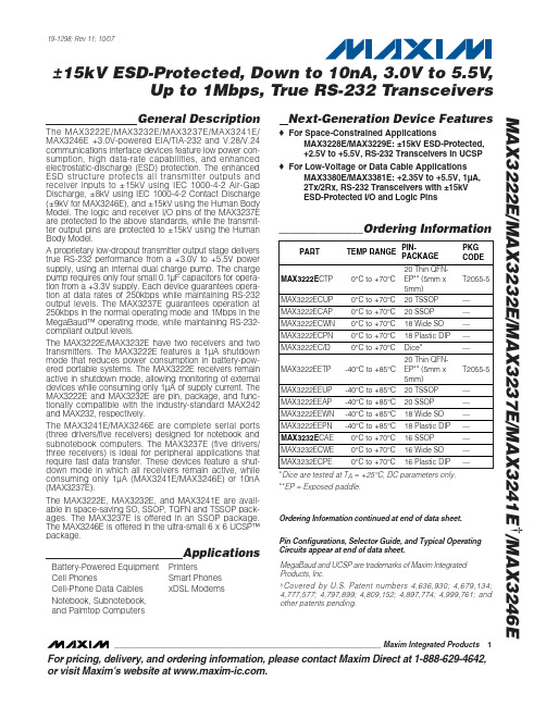
For pricing, delivery, and ordering information, please contact Maxim Direct at 1-888-629-4642,or visit Maxim's website at .General DescriptionThe MAX3222E/MAX3232E/MAX3237E/MAX3241E/MAX3246E +3.0V-powered EIA/TIA-232 and V.28/V.24communications interface devices feature low power con-sumption, high data-rate capabilities, and enhanced electrostatic-discharge (ESD) protection. The enhanced ESD structure protects all transmitter outputs and receiver inputs to ±15kV using IEC 1000-4-2 Air-G ap Discharge, ±8kV using IEC 1000-4-2 Contact Discharge (±9kV for MAX3246E), and ±15kV using the Human Body Model. The logic and receiver I/O pins of the MAX3237E are protected to the above standards, while the transmit-ter output pins are protected to ±15kV using the Human Body Model.A proprietary low-dropout transmitter output stage delivers true RS-232 performance from a +3.0V to +5.5V power supply, using an internal dual charge pump. The charge pump requires only four small 0.1µF capacitors for opera-tion from a +3.3V supply. Each device guarantees opera-tion at data rates of 250kbps while maintaining RS-232output levels. The MAX3237E guarantees operation at 250kbps in the normal operating mode and 1Mbps in the MegaBaud™ operating mode, while maintaining RS-232-compliant output levels.The MAX3222E/MAX3232E have two receivers and two transmitters. The MAX3222E features a 1µA shutdown mode that reduces power consumption in battery-pow-ered portable systems. The MAX3222E receivers remain active in shutdown mode, allowing monitoring of external devices while consuming only 1µA of supply current. The MAX3222E and MAX3232E are pin, package, and func-tionally compatible with the industry-standard MAX242and MAX232, respectively.The MAX3241E/MAX3246E are complete serial ports (three drivers/five receivers) designed for notebook and subnotebook computers. The MAX3237E (five drivers/three receivers) is ideal for peripheral applications that require fast data transfer. These devices feature a shut-down mode in which all receivers remain active, while consuming only 1µA (MAX3241E/MAX3246E) or 10nA (MAX3237E).The MAX3222E, MAX3232E, and MAX3241E are avail-able in space-saving SO, SSOP, TQFN and TSSOP pack-ages. The MAX3237E is offered in an SSOP package.The MAX3246E is offered in the ultra-small 6 x 6 UCSP™package.ApplicationsBattery-Powered Equipment PrintersCell PhonesSmart Phones Cell-Phone Data Cables xDSL ModemsNotebook, Subnotebook,and Palmtop ComputersNext-Generation Device Features♦For Space-Constrained ApplicationsMAX3228E/MAX3229E: ±15kV ESD-Protected, +2.5V to +5.5V, RS-232 Transceivers in UCSP ♦For Low-Voltage or Data Cable ApplicationsMAX3380E/MAX3381E: +2.35V to +5.5V, 1µA, 2Tx/2Rx, RS-232 Transceivers with ±15kV ESD-Protected I/O and Logic PinsMAX3222E/MAX3232E/MAX3237E/MAX3241E †/MAX3246E±15kV ESD-Protected, Down to 10nA, 3.0V to 5.5V ,Up to 1Mbps, True RS-232 Transceivers________________________________________________________________Maxim Integrated Products 119-1298; Rev 11; 10/07Ordering Information continued at end of data sheet.*Dice are tested at T A = +25°C, DC parameters only.**EP = Exposed paddle.Pin Configurations, Selector Guide, and Typical Operating Circuits appear at end of data sheet.MegaBaud and UCSP are trademarks of Maxim Integrated Products, Inc.†Covered by U.S. Patent numbers 4,636,930; 4,679,134;4,777,577; 4,797,899; 4,809,152; 4,897,774; 4,999,761; and other patents pending.M A X 3222E /M A X 3232E /M A X 3237E /M A X 3241E †/M A X 3246EUp to 1Mbps, True RS-232 TransceiversABSOLUTE MAXIMUM RATINGSELECTRICAL CHARACTERISTICS(V CC = +3V to +5.5V, C1–C4 = 0.1µF, T A = T MIN to T MAX , unless otherwise noted. Typical values are at T A = +25°C.) (Notes 3, 4)Stresses beyond those listed under “Absolute Maximum Ratings” may cause permanent damage to the device. These are stress ratings only, and functional operation of the device at these or any other conditions beyond those indicated in the operational sections of the specifications is not implied. Exposure to absolute maximum rating conditions for extended periods may affect device reliability.V CC to GND..............................................................-0.3V to +6V V+ to GND (Note 1)..................................................-0.3V to +7V V- to GND (Note 1)...................................................+0.3V to -7V V+ + |V-| (Note 1).................................................................+13V Input Voltages T_IN, EN , SHDN , MBAUD to GND ........................-0.3V to +6V R_IN to GND.....................................................................±25V Output Voltages T_OUT to GND...............................................................±13.2V R_OUT, R_OUTB (MAX3241E)................-0.3V to (V CC + 0.3V)Short-Circuit Duration, T_OUT to GND.......................Continuous Continuous Power Dissipation (T A = +70°C)16-Pin SSOP (derate 7.14mW/°C above +70°C)..........571mW 16-Pin TSSOP (derate 9.4mW/°C above +70°C).......754.7mW 16-Pin TQFN (derate 20.8mW/°C above +70°C).....1666.7mW 16-Pin Wide SO (derate 9.52mW/°C above +70°C).....762mW 18-Pin Wide SO (derate 9.52mW/°C above +70°C).....762mW 18-Pin PDIP (derate 11.11mW/°C above +70°C)..........889mW 20-Pin TQFN (derate 21.3mW/°C above +70°C)........1702mW 20-Pin TSSOP (derate 10.9mW/°C above +70°C)........879mW 20-Pin SSOP (derate 8.00mW/°C above +70°C)..........640mW 28-Pin SSOP (derate 9.52mW/°C above +70°C)..........762mW 28-Pin Wide SO (derate 12.50mW/°C above +70°C).............1W 28-Pin TSSOP (derate 12.8mW/°C above +70°C)......1026mW 32-Lead Thin QFN (derate 33.3mW/°C above +70°C)..2666mW 6 x 6 UCSP (derate 12.6mW/°C above +70°C).............1010mW Operating Temperature Ranges MAX32_ _EC_ _...................................................0°C to +70°C MAX32_ _EE_ _.................................................-40°C to +85°C Storage Temperature Range.............................-65°C to +150°C Lead Temperature (soldering, 10s).................................+300°C Bump Reflow Temperature (Note 2)Infrared, 15s..................................................................+200°C Vapor Phase, 20s..........................................................+215°C Note 1:V+ and V- can have maximum magnitudes of 7V, but their absolute difference cannot exceed 13V.Note 2:This device is constructed using a unique set of packaging techniques that impose a limit on the thermal profile the devicecan be exposed to during board-level solder attach and rework. This limit permits only the use of the solder profiles recom-mended in the industry-standard specification, JEDEC 020A, paragraph 7.6, Table 3 for IR/VPR and convection reflow.Preheating is required. Hand or wave soldering is not allowed.MAX3222E/MAX3232E/MAX3237E/MAX3241E †/MAX3246EUp to 1Mbps, True RS-232 Transceivers_______________________________________________________________________________________3M A X 3222E /M A X 3232E /M A X 3237E /M A X 3241E †/M A X 3246EUp to 1Mbps, True RS-232 Transceivers4_______________________________________________________________________________________TIMING CHARACTERISTICS—MAX3237E(V CC = +3V to +5.5V, C1–C4 = 0.1µF, T A = T MIN to T MAX , unless otherwise noted. Typical values are at T A = +25°C.) (Note 3)±10%. MAX3237E: C1–C4 = 0.1µF tested at +3.3V ±5%, C1–C4 = 0.22µF tested at +3.3V ±10%; C1 = 0.047µF, C2, C3, C4 =0.33µF tested at +5.0V ±10%. MAX3246E; C1-C4 = 0.22µF tested at +3.3V ±10%; C1 = 0.22µF, C2, C3, C4 = 0.54µF tested at 5.0V ±10%.Note 4:MAX3246E devices are production tested at +25°C. All limits are guaranteed by design over the operating temperature range.Note 5:The MAX3237E logic inputs have an active positive feedback resistor. The input current goes to zero when the inputs are atthe supply rails.Note 6:MAX3241EEUI is specified at T A = +25°C.Note 7:Transmitter skew is measured at the transmitter zero crosspoints.TIMING CHARACTERISTICS—MAX3222E/MAX3232E/MAX3241E/MAX3246EMAX3222E/MAX3232E/MAX3237E/MAX3241E †/MAX3246EUp to 1Mbps, True RS-232 Transceivers_______________________________________________________________________________________5-6-4-202460MAX3237ETRANSMITTER OUTPUT VOLTAGE vs. LOAD CAPACITANCE (MBAUD = GND)LOAD CAPACITANCE (pF)T R A N S M I T T E R O U T P U T V O L T A G E (V )10001500500200025003000531-1-3-5-6-2-42046-5-31-135010001500500200025003000LOAD CAPACITANCE (pF)T R A N S M I T T E R O U T P U T V O L T A G E (V )MAX3237ETRANSMITTER OUTPUT VOLTAGEvs. LOAD CAPACITANCE-7.5-5.0-2.502.55.07.5MAX3237ETRANSMITTER OUTPUT VOLTAGE vs. LOAD CAPACITANCE (MBAUD = V CC )LOAD CAPACITANCE (pF)T R A N S M I T T E R O U T P U T V O L T A G E (V )500100015002000__________________________________________Typical Operating Characteristics(V CC = +3.3V, 250kbps data rate, 0.1µF capacitors, all transmitters loaded with 3k Ωand C L , T A = +25°C, unless otherwise noted.)-6-5-4-3-2-10123456010002000300040005000MAX3241ETRANSMITTER OUTPUT VOLTAGEvs. LOAD CAPACITANCELOAD CAPACITANCE (pF)T R A N S M I T T E R O U T P U T V O L T A G E (V)302010405060020001000300040005000MAX3241EOPERATING SUPPLY CURRENT vs. LOAD CAPACITANCELOAD CAPACITANCE (pF)S U P P L Y C U R R E N T (m A )04286121014010002000300040005000MAX3241ESLEW RATE vs. LOAD CAPACITANCEM A X 3237E t o c 05LOAD CAPACITANCE (pF)S L E W R A T E (V /μs )-6-5-4-3-2-10123456010002000300040005000MAX3222E/MAX3232ETRANSMITTER OUTPUT VOLTAGEvs. LOAD CAPACITANCELOAD CAPACITANCE (pF)T R A N S M I T T E R O U T P UT V O L T A G E (V )624108141216010002000300040005000MAX3222E/MAX3232ESLEW RATE vs. LOAD CAPACITANCELOAD CAPACITANCE (pF)S L E W R A T E (V /μs)2520155103530404520001000300040005000MAX3222E/MAX3232E OPERATING SUPPLY CURRENT vs. LOAD CAPACITANCELOAD CAPACITANCE (pF)S U P P L Y C U R R E N T (m A )M A X 3222E /M A X 3232E /M A X 3237E /M A X 3241E †/M A X 3246EUp to 1Mbps, True RS-232 Transceivers6_______________________________________________________________________________________Typical Operating Characteristics (continued)(V CC = +3.3V, 250kbps data rate, 0.1µF capacitors, all transmitters loaded with 3k Ωand C L , T A = +25°C, unless otherwise noted.)20604080100MAX3237ETRANSMITTER SKEW vs. LOAD CAPACITANCE(MBAUD = V CC )LOAD CAPACITANCE (pF)100015005002000T R A N S M I T T E R S K E W (n s )-6-2-42046-3-51-1352.03.03.52.54.04.55.0SUPPLY VOLTAGE (V)T R A N S M I T T E R O U T P U T V O L T A G E (V )MAX3237ETRANSMITTER OUTPUT VOLTAGE vs. SUPPLY VOLTAGE (MBAUD = GND)10203040502.0MAX3237E SUPPLY CURRENT vs. SUPPLY VOLTAGE (MBAUD = GND)SUPPLY VOLTAGE (V)S U P P L Y C U R R E N T (m A )3.03.52.54.04.55.0MAX3246ETRANSMITTER OUTPUT VOLTAGEvs. LOAD CAPACITANCELOAD CAPACITANCE (pF)T R A N S M I T T E R O U T P U T V O L T A G E (V )4000300010002000-5-4-3-2-101234567-65000468101214160MAX3246ESLEW RATE vs. LOAD CAPACITANCELOAD CAPACITANCE (pF)S L EW R A T E (V /μs )200030001000400050001020304050600MAX3246EOPERATING SUPPLY CURRENT vs. LOAD CAPACITANCEM A X 3237E t o c 17LOAD CAPACITANCE (pF)S U P P L Y C U R R EN T (m A )1000200030004000500055453525155024681012MAX3237ESLEW RATE vs. LOAD CAPACITANCE(MBAUD = GND)LOAD CAPACITANCE (pF)S L E W R A T E (V /μs )10001500500200025003000010203050406070MAX3237ESLEW RATE vs. LOAD CAPACITANCE(MBAUD = V CC )LOAD CAPACITANCE (pF)S L E W R A T E (V /μs )5001000150020001020304050MAX3237ESUPPLY CURRENT vs. LOAD CAPACITANCE WHEN TRANSMITTING DATA (MBAUD = GND)LOAD CAPACITANCE (pF)S U P P L Y C U R R E N T (m A )10001500500200025003000MAX3222E/MAX3232E/MAX3237E/MAX3241E †/MAX3246EUp to 1Mbps, True RS-232 Transceivers_______________________________________________________________________________________7Pin DescriptionM A X 3222E /M A X 3232E /M A X 3237E /M A X 3241E †/M A X 3246EUp to 1Mbps, True RS-232 Transceivers8_______________________________________________________________________________________MAX3222E/MAX3232E/MAX3237E/MAX3241E †/MAX3246EUp to 1Mbps, True RS-232 Transceivers_______________________________________________________________________________________9Detailed DescriptionDual Charge-Pump Voltage ConverterThe MAX3222E/MAX3232E/MAX3237E/MAX3241E/MAX3246Es’ internal power supply consists of a regu-lated dual charge pump that provides output voltages of +5.5V (doubling charge pump) and -5.5V (inverting charge pump) over the +3.0V to +5.5V V CC range. The charge pump operates in discontinuous mode; if the output voltages are less than 5.5V, the charge pump is enabled, and if the output voltages exceed 5.5V, the charge pump is disabled. Each charge pump requires a flying capacitor (C1, C2) and a reservoir capacitor (C3, C4) to generate the V+ and V- supplies (Figure 1).RS-232 TransmittersThe transmitters are inverting level translators that con-vert TTL/CMOS-logic levels to ±5V EIA/TIA-232-compli-ant levels.The MAX3222E/MAX3232E/MAX3237E/MAX3241E/MAX3246E transmitters guarantee a 250kbps data rate with worst-case loads of 3k Ωin parallel with 1000pF,providing compatibility with PC-to-PC communication software (such as LapLink™). Transmitters can be par-alleled to drive multiple receivers or mice.The MAX3222E/MAX3237E/MAX3241E/MAX3246E transmitters are disabled and the outputs are forcedinto a high-impedance state when the device is in shut-down mode (SHDN = G ND). The MAX3222E/MAX3232E/MAX3237E/MAX3241E/MAX3246E permit the outputs to be driven up to ±12V in shutdown.The MAX3222E/MAX3232E/MAX3241E/MAX3246E transmitter inputs do not have pullup resistors. Connect unused inputs to GND or V CC . The MAX3237E’s trans-mitter inputs have a 400k Ωactive positive-feedback resistor, allowing unused inputs to be left unconnected.MAX3237E MegaBaud OperationFor higher-speed serial communications, the MAX3237E features MegaBaud operation. In MegaBaud operating mode (MBAUD = V CC ), the MAX3237E transmitters guarantee a 1Mbps data rate with worst-case loads of 3k Ωin parallel with 250pF for +3.0V < V CC < +4.5V. For +5V ±10% operation, the MAX3237E transmitters guarantee a 1Mbps data rate into worst-case loads of 3k Ωin parallel with 1000pF.RS-232 ReceiversThe receivers convert RS-232 signals to CMOS-logic output levels. The MAX3222E/MAX3237E/MAX3241E/MAX3246E receivers have inverting three-state outputs.Drive EN high to place the receiver(s) into a high-impedance state. Receivers can be either active or inactive in shutdown (Table 1).Figure 1. Slew-Rate Test CircuitsLapLink is a trademark of Traveling Software.M A X 3222E /M A X 3232E /M A X 3237E /M A X 3241E †/M A X 3246EUp to 1Mbps, True RS-232 Transceivers10______________________________________________________________________________________The complementary outputs on the MAX3237E/MAX3241E (R_OUTB) are always active, regardless of the state of EN or SHDN . This allows the device to be used for ring indicator applications without forward biasing other devices connected to the receiver outputs. This is ideal for systems where V CC drops to zero in shutdown to accommodate peripherals such as UARTs (Figure 2).MAX3222E/MAX3237E/MAX3241E/MAX3246E Shutdown ModeSupply current falls to less than 1µA in shutdown mode (SHDN = low). The MAX3237E’s supply current falls to10nA (typ) when all receiver inputs are in the invalid range (-0.3V < R_IN < +0.3). When shut down, the device’s charge pumps are shut off, V+ is pulled down to V CC , V- is pulled to ground, and the transmitter out-puts are disabled (high impedance). The time required to recover from shutdown is typically 100µs, as shown in Figure 3. Connect SHDN to V CC if shutdown mode is not used. SHDN has no effect on R_OUT or R_OUTB (MAX3237E/MAX3241E).±15kV ESD ProtectionAs with all Maxim devices, ESD-protection structures are incorporated to protect against electrostatic dis-charges encountered during handling and assembly.The driver outputs and receiver inputs of the MAX3222E/MAX3232E/MAX3237E/MAX3241E/MAX3246E have extra protection against static electricity. Maxim’s engineers have developed state-of-the-art structures to protect these pins against ESD of ±15kV without damage.The ESD structures withstand high ESD in all states:normal operation, shutdown, and powered down. After an ESD event, Maxim’s E versions keep working without latchup, whereas competing RS-232 products can latch and must be powered down to remove latchup.Furthermore, the MAX3237E logic I/O pins also have ±15kV ESD protection. Protecting the logic I/O pins to ±15kV makes the MAX3237E ideal for data cable applications.SHDN T2OUTT1OUT5V/div2V/divV CC = 3.3V C1–C4 = 0.1μFFigure 3. Transmitter Outputs Recovering from Shutdown or Powering UpMAX3222E/MAX3232E/MAX3237E/MAX3241E †/MAX3246EUp to 1Mbps, True RS-232 TransceiversESD protection can be tested in various ways; the transmitter outputs and receiver inputs for the MAX3222E/MAX3232E/MAX3241E/MAX3246E are characterized for protection to the following limits:•±15kV using the Human Body Model•±8kV using the Contact Discharge method specified in IEC 1000-4-2•±9kV (MAX3246E only) using the Contact Discharge method specified in IEC 1000-4-2•±15kV using the Air-G ap Discharge method speci-fied in IEC 1000-4-2Figure 4a. Human Body ESD Test ModelFigure 4b. Human Body Model Current WaveformFigure 5a. IEC 1000-4-2 ESD Test Model Figure 5b. IEC 1000-4-2 ESD Generator Current WaveformM A X 3222E /M A X 3232E /M A X 3237E /M A X 3241E †/M A X 3246EUp to 1Mbps, True RS-232 Transceiverscharacterized for protection to ±15kV per the Human Body Model.ESD Test ConditionsESD performance depends on a variety of conditions.Contact Maxim for a reliability report that documents test setup, test methodology, and test results.Human Body ModelFigure 4a shows the Human Body Model, and Figure 4b shows the current waveform it generates when dis-charged into a low impedance. This model consists of a 100pF capacitor charged to the ESD voltage of interest,which is then discharged into the test device through a 1.5k Ωresistor.IEC 1000-4-2The IEC 1000-4-2 standard covers ESD testing and performance of finished equipment; it does not specifi-cally refer to integrated circuits. The MAX3222E/MAX3232E/MAX3237E/MAX3241E/MAX3246E help you design equipment that meets level 4 (the highest level)of IEC 1000-4-2, without the need for additional ESD-protection components.The major difference between tests done using the Human Body Model and IEC 1000-4-2 is higher peak current in IEC 1000-4-2, because series resistance is lower in the IEC 1000-4-2 model. Hence, the ESD with-stand voltage measured to IEC 1000-4-2 is generally lower than that measured using the Human Body Model. Figure 5a shows the IEC 1000-4-2 model, and Figure 5b shows the current waveform for the ±8kV IEC 1000-4-2 level 4 ESD Contact Discharge test. The Air-G ap Discharge test involves approaching the device with a charged probe. The Contact Discharge method connects the probe to the device before the probe is energized.Machine ModelThe Machine Model for ESD tests all pins using a 200pF storage capacitor and zero discharge resis-tance. Its objective is to emulate the stress caused by contact that occurs with handling and assembly during manufacturing. All pins require this protection during manufacturing, not just RS-232 inputs and outputs.Therefore, after PC board assembly, the Machine Model is less relevant to I/O ports.Table 2. Required Minimum Capacitor ValuesFigure 6a. MAX3241E Transmitter Output Voltage vs. Load Current Per TransmitterTable 3. Logic-Family Compatibility with Various Supply VoltagesMAX3222E/MAX3232E/MAX3237E/MAX3241E †/MAX3246EUp to 1Mbps, True RS-232 TransceiversApplications InformationCapacitor SelectionThe capacitor type used for C1–C4 is not critical for proper operation; polarized or nonpolarized capacitors can be used. The charge pump requires 0.1µF capaci-tors for 3.3V operation. For other supply voltages, see Table 2 for required capacitor values. Do not use val-ues smaller than those listed in Table 2. Increasing the capacitor values (e.g., by a factor of 2) reduces ripple on the transmitter outputs and slightly reduces power consumption. C2, C3, and C4 can be increased without changing C1’s value. However, do not increase C1without also increasing the values of C2, C3, C4,and C BYPASS to maintain the proper ratios (C1 to the other capacitors).When using the minimum required capacitor values,make sure the capacitor value does not degradeexcessively with temperature. If in doubt, use capaci-tors with a larger nominal value. The capacitor’s equiv-alent series resistance (ESR), which usually rises at low temperatures, influences the amount of ripple on V+and V-.Power-Supply DecouplingIn most circumstances, a 0.1µF V CC bypass capacitor is adequate. In applications sensitive to power-supply noise, use a capacitor of the same value as charge-pump capacitor C1. Connect bypass capacitors as close to the IC as possible.Operation Down to 2.7VTransmitter outputs meet EIA/TIA-562 levels of ±3.7V with supply voltages as low as 2.7V.Figure 6b. Mouse Driver Test CircuitM A X 3222E /M A X 3232E /M A X 3237E /M A X 3241E †/M A X 3246EUp to 1Mbps, True RS-232 TransceiversFigure 7. Loopback Test CircuitT1IN T1OUTR1OUT5V/div5V/div5V/divV CC = 3.3V C1–C4 = 0.1μFFigure 8. MAX3241E Loopback Test Result at 120kbps T1INT1OUTR1OUT5V/div5V/div5V/divV CC = 3.3V, C1–C4 = 0.1μFFigure 9. MAX3241E Loopback Test Result at 250kbps+5V 0+5V 0-5V +5VT_INT_OUT5k Ω + 250pFR_OUTV CC = 3.3V C1–C4 = 0.1μFFigure 10. MAX3237E Loopback Test Result at 1000kbps (MBAUD = V CC )Transmitter Outputs Recoveringfrom ShutdownFigure 3 shows two transmitter outputs recovering from shutdown mode. As they become active, the two trans-mitter outputs are shown going to opposite RS-232 levels (one transmitter input is high; the other is low). Each transmitter is loaded with 3k Ωin parallel with 2500pF.The transmitter outputs display no ringing or undesir-able transients as they come out of shutdown. Note thatthe transmitters are enabled only when the magnitude of V- exceeds approximately -3.0V.Mouse DrivabilityThe MAX3241E is designed to power serial mice while operating from low-voltage power supplies. It has been tested with leading mouse brands from manu-facturers such as Microsoft and Logitech. The MAX3241E successfully drove all serial mice tested and met their current and voltage requirements.MAX3222E/MAX3232E/MAX3237E/MAX3241E †/MAX3246EUp to 1Mbps, True RS-232 TransceiversFigure 6a shows the transmitter output voltages under increasing load current at +3.0V. Figure 6b shows a typical mouse connection using the MAX3241E.High Data RatesThe MAX3222E/MAX3232E/MAX3237E/MAX3241E/MAX3246E maintain the RS-232 ±5V minimum transmit-ter output voltage even at high data rates. Figure 7shows a transmitter loopback test circuit. Figure 8shows a loopback test result at 120kbps, and Figure 9shows the same test at 250kbps. For Figure 8, all trans-mitters were driven simultaneously at 120kbps into RS-232 loads in parallel with 1000pF. For Figure 9, a single transmitter was driven at 250kbps, and all transmitters were loaded with an RS-232 receiver in parallel with 1000pF.The MAX3237E maintains the RS-232 ±5.0V minimum transmitter output voltage at data rates up to 1Mbps.Figure 10 shows a loopback test result at 1Mbps with MBAUD = V CC . For Figure 10, all transmitters were loaded with an RS-232 receiver in parallel with 250pF.Interconnection with 3V and 5V LogicThe MAX3222E/MAX3232E/MAX3237E/MAX3241E/MAX3246E can directly interface with various 5V logic families, including ACT and HCT CMOS. See Table 3for more information on possible combinations of inter-connections.UCSP ReliabilityThe UCSP represents a unique packaging form factor that may not perform equally to a packaged product through traditional mechanical reliability tests. UCSP reliability is integrally linked to the user’s assembly methods, circuit board material, and usage environ-ment. The user should closely review these areas when considering use of a UCSP package. Performance through Operating Life Test and Moisture Resistance remains uncompromised as the wafer-fabrication process primarily determines it.Mechanical stress performance is a greater considera-tion for a UCSP package. UCSPs are attached through direct solder contact to the user’s PC board, foregoing the inherent stress relief of a packaged product lead frame. Solder joint contact integrity must be consid-ered. Table 4 shows the testing done to characterize the UCSP reliability performance. In conclusion, the UCSP is capable of performing reliably through envi-ronmental stresses as indicated by the results in the table. Additional usage data and recommendations are detailed in the UCSP application note, which can be found on Maxim’s website at .Table 4. Reliability Test DataM A X 3222E /M A X 3232E /M A X 3237E /M A X 3241E †/M A X 3246EUp to 1Mbps, True RS-232 Transceivers__________________________________________________________Pin ConfigurationsMAX3222E/MAX3232E/MAX3237E/MAX3241E †/MAX3246EUp to 1Mbps, True RS-232 TransceiversPin Configurations (continued)M A X 3222E /M A X 3232E /M A X 3237E /M A X 3241E †/M A X 3246EUp to 1Mbps, True RS-232 Transceivers__________________________________________________Typical Operating CircuitsMAX3222E/MAX3232E/MAX3237E/MAX3241E †/MAX3246EUp to 1Mbps, True RS-232 Transceivers_____________________________________Typical Operating Circuits (continued)M A X 3222E /M A X 3232E /M A X 3237E /M A X 3241E †/M A X 3246EUp to 1Mbps, True RS-232 Transceivers_____________________________________Typical Operating Circuits (continued)MAX3222E/MAX3232E/MAX3237E/MAX3241E †/MAX3246EUp to 1Mbps, True RS-232 Transceivers______________________________________________________________________________________21Selector Guide___________________Chip InformationTRANSISTOR COUNT:MAX3222E/MAX3232E: 1129MAX3237E: 2110MAX3241E: 1335MAX3246E: 842PROCESS: BICMOSOrdering Information (continued)†Requires solder temperature profile described in the AbsoluteMaximum Ratings section. UCSP Reliability is integrally linked to the user’s assembly methods, circuit board material, and environment. Refer to the UCSP Reliability Notice in the UCSP Reliability section of this datasheet for more information.**EP = Exposed paddle.。
SR310-T3中文资料

SR32 – SR3103.0A SURFACE MOUNT SCHOTTKY BARRIER DIODECharacteristicSymbol SR32SR33SR34SR35SR36SR38SR39SR310UnitPeak Repetitive Reverse Voltage Working Peak Reverse Voltage DC Blocking Voltage V RRMV RWM V R 20304050608090100V RMS Reverse VoltageV R(RMS)1421283542566471V Average Rectified Output Current @T L = 75°C I O 3.0A Non-Repetitive Peak Forward Surge Current 8.3ms Single half sine-wave superimposed on rated load (JEDEC Method)I FSM 100AForward Voltage @I F = 3.0A V FM 0.500.750.85V Peak Reverse Current @T A = 25°C At Rated DC Blocking Voltage @T A = 100°C I RM 0.520mA Typical Thermal Resistance (Note 1)R JL R JA 2075°C/W Operating Temperature Range T j -65 to +125°C Storage Temperature RangeT STG-65 to +150°CNote: 1. Mounted on P .C. Board with 14mm 2 copper pad area.WTE0.010.11.0100.20.40.60.81.0I ,I N S T A N T A N E O U S F O R W A R D C U R R E N T (A )F V ,INSTANTANEOUS FORWARD VOLTAGE (V)Fig.2T ypical Forward CharacteristicsF020406080100110100I ,P E A K F O R W A R D S U R G E C U R R E N T (A )F NUMBER OF CYCLES AT 60 HzFig.3Max Non-Repetitive Peak Fwd Surge Current1010010000.1110100C , J U N C T I O N C A P A C I T A N C E (p F )J V , REVERSE VOL TAGE (V)Fig.4 T ypical Junction CapacitanceR 020406080100120140I ,I N S T A N T A N E O U S R E V E R S E C U R R E N T (m A )R PERCENT OF RATED PEAK REVERSE VOLTAGE (%)Fig.5T ypical Reverse Characteristics100101.00.10.011k0.51.0255075100125150I A V E R A G E F O R W A R D C U R R E N T (A )O ,T , LEAD TEMPERATURE (ºC)Fig.1Forward Current Derating CurveL 1.52.02.53.0MARKING INFORMATION RECOMMENDED FOOTPRINTPACKAGING INFORMATIONORDERING INFORMATIONProduct No.Package TypeShipping QuantitySR32-T3SMB 3000/Tape & Reel SR33-T3SMB 3000/Tape & Reel SR34-T3SMB 3000/Tape & Reel SR35-T3SMB 3000/Tape & Reel SR36-T3SMB 3000/Tape & Reel SR38-T3SMB 3000/Tape & Reel SR39-T3SMB 3000/Tape & Reel SR310-T3SMB3000/Tape & Reel1. Shipping quantity given is for minimum packing quantity only. For minimumorder quantity, please consult the Sales Department.2.To order RoHS / Lead Free version (with Lead Free finish), add “-LF” suffix to part number above. For example, SR32-T3-LF .Won-Top Electronics Co., Ltd (WTE) has checked all information carefully and believes it to be correct and accurate. However, WTE cannot assume any responsibility for inaccuracies. Furthermore, this information does not give the purchaser of semiconductor devices any license under patent rights to manufacturer. WTE reserves the right to change any or all information herein without further notice.WARNING : DO NOT USE IN LIFE SUPPORT EQUIPMENT. WTE power semiconductor products are not authorized for use as critical components in life support devices or systems without the express written approval.We power your everyday.Won-Top Electronics Co., Ltd.No. 44 Yu Kang North 3rd Road, Chine Chen Dist., Kaohsiung, Taiwan Phone: 886-7-822-5408 or 886-7-822-5410Fax: 886-7-822-5417Email: sales@Internet: 。
ER3G中文资料

100 200 400
1000
元器件交易网
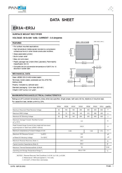
ER3A thru ER3J
Figure 4 Typical Reverse Characteristics 1000 600 400
MCC
Figure 5 Peak Forward Surge Current 150
°C
Average Forward Rectified Current - Amperesversus Lead Temperature -°C
100 60 40
20 pF
10
6 4
2 1
.1 .2 .4
TJ=25°C
12
4
Volts
10 20 40
Junction Capacitance - pFversus Reverse Voltage - Volts
Figure 3 Junction Capacitance
MCC
Figure 2 Forward Derating Curve
3.0
2.5
2.0
1.5 Amps
1.0
.5 Single Phase, Half Wave
60Hz Resistive or Inductive Load
0 40
60
80 100 120 140 160
IFM = 3.0A; TJ = 25°C
Maximum DC Reverse Current At Rated DC Blocking Voltage
IR
5µA TJ = 25°C
200µA TJ = 100°C
Maximum Reverse Recovery Time Typical Junction Capacitance
ER3B-T3中文资料
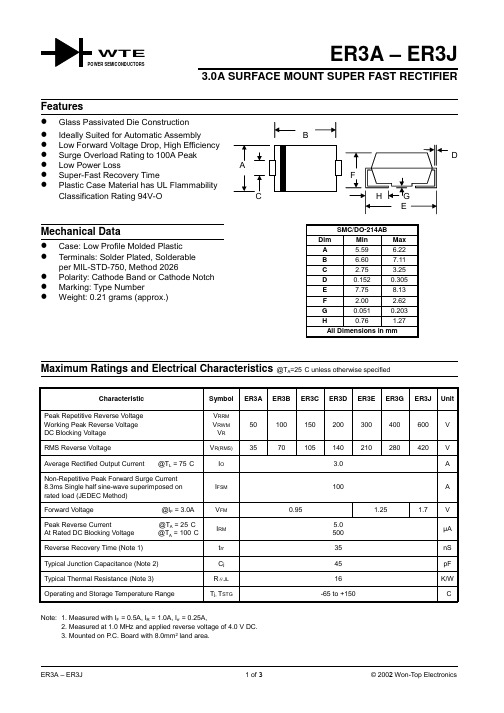
ER3A – ER3J3.0A SURFACE MOUNT SUPER FAST RECTIFIERCharacteristic Symbol ER3A ER3B ER3C ER3D ER3E ER3G ER3J UnitPeak Repetitive Reverse Voltage Working Peak Reverse Voltage DC Blocking Voltage V RRMV RWMV R50100150200300400600VRMS Reverse Voltage V R(RMS)3570105140210280420V Average Rectified Output Current @T L = 75°C I O 3.0A Non-Repetitive Peak Forward Surge Current8.3ms Single half sine-wave superimposed onrated load (JEDEC Method)I FSM100A Forward Voltage @I F = 3.0A V FM0.95 1.25 1.7VPeak Reverse Current @T A = 25°C At Rated DC Blocking Voltage @T A = 100°C I RM5.0500µAReverse Recovery Time (Note 1)t rr35nS Typical Junction Capacitance (Note 2)C j45pF Typical Thermal Resistance (Note 3)R JL16K/W Operating and Storage Temperature Range T j, T STG-65 to +150°CNote: 1. Measured with I F = 0.5A, I R = 1.0A, I rr = 0.25A,2. Measured at 1.0 MHz and applied reverse voltage of 4.0 V DC.3. Mounted on P.C. Board with 8.0mm2 land area.WTE0.010.11.0101000.61.0 1.4 1.8V ,INSTANTANEOUS FORWARD VOLTAGE (V)Fig.2Typical Forward CharacteristicsF I ,I N S T A N T A N E O U S F O R W A R D C U R R E N T (A )F 10100200110100I ,P E A K F O R W A R D S U R G E C U R R E N T (A )F S M NUMBER OF CYCLES AT 60Hz Fig.3Peak Forward Surge CurrentSet time base for 5/10ns/cm+0.5A0A -0.25A-1.0ANotes:1.Rise Time =7.0ns max.Input Impedance =1.0M ,22pF.2.Rise Time =10ns max.Input Impedance =50.ΩΩFig.5Reverse Recovery Time Characteristic and Test Circuit101001000110100C ,C A P A C I T A N C E (p F )j V ,REVERSE VOLTAGE (V)Fig.4Typical Junction CapacitanceR 012340255075100125150175I ,A V E R A G E F W D R E C T I F I E D C U R R E N T (A )(A V )T ,LEAD TEMPERATURE ( C)Fig.1Forward Current Derating CurveL °ORDERING INFORMATIONProduct No.!Package TypeShipping QuantityER3A-T1SMC 500/Tape &Reel ER3A-T3SMC 3000/Tape & Reel ER3B-T1SMC 500/Tape & Reel ER3B-T3SMC 3000/Tape & Reel ER3C-T1SMC 500/Tape & Reel ER3C-T3SMC 3000/Tape & Reel ER3D-T1SMC 500/Tape & Reel ER3D-T3SMC 3000/Tape & Reel ER3E-T1SMC 500/Tape & Reel ER3E-T3SMC 3000/Tape & Reel ER3G-T1SMC 500/Tape & Reel ER3G-T3SMC 3000/Tape & Reel ER3J-T1SMC 500/Tape & Reel ER3J-T3SMC3000/Tape & ReelProducts listed in bold are WTE Preferred devices.!T1 suffix refers to a 7” reel. T3 suffix refers to a 13” reel.Shipping quantity given is for minimum packing quantity only. For minimum order quantity, please consult the Sales Department.RECOMMENDED FOOTPRINTinches(mm)Won-Top Electronics Co., Ltd (WTE) has checked all information carefully and believes it to be correct and accurate. However, WTE cannot assume any responsibility for inaccuracies. Furthermore, this information does not give the purchaser of semiconductor devices any license under patent rights to manufacturer. WTE reserves the right to change any or all information herein without further notice.WARNING : DO NOT USE IN LIFE SUPPORT EQUIPMENT. WTE power semiconductor products are not authorized for use as critical components in life support devices or systems without the express written approval.We power your everyday.Won-Top Electronics Co., Ltd.No. 44 Yu Kang North 3rd Road, Chine Chen Dist., Kaohsiung, Taiwan Phone: 886-7-822-5408 or 886-7-822-5410Fax: 886-7-822-5417Email: sales@Internet: 。
U3G1,U3G2,T3P1,T3P2
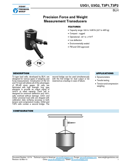
Precision Force and Weight Measurement TransducersU3G1, U3G2, T3P1,T3P2BLHD ocument N umber : 12174Technical contact in Americas: a@ , Europe: pw.eur@ ,R evision: 02-Mar-10China: pw.prc@ , Taiwan: pw.roc@ 1FEATURES•Capacity range: 500 to 100K lb (227 to 45K kg) •Compact - rugged•Operational: -30° to +175°F •Low deflection •Environmentally sealed •FM and CSA approvedDESCRIPTIONT3 type load cells, developed by BLH, are designed for various types of weighing and force measurement. Construction of the U3and T3 load cell utilizes all of the advantages of SR-4® strain gages. All cells are fabricated with high strength ‘ring’ type elements to provide an output signal of 3mV/V at rated capacity. Each cell is designed for minimum deflection and 150%safe overload without damage. U3G1 and U3G2 universal load cells are shipped with calibration data verifying accuracy in both tension and compression modes. U3G2 and T3P2 cells contain a second bridge. Thesecond bridge can be used simultaneously with the first bridge for dual output or be reserved as a backup in case of failure.APPLICATIONS•Dynamometers •Tensile testing•Tension and compression weighingCONFIGURATIONU3G1, U3G2, T3P1,T3P2BLHPrecision Force and Weight Measurement T ransducers Technical contact in Americas: a@ , Europe: pw.eur@ ,D ocument N umber : 121742China: pw.prc@ , Taiwan: pw.roc@R evision: 02-Mar-10DIMENSIONSCAP (lb)A B DIA. C DIA.D E F K DIA.L (TAPPED)N DIA.500 - 300049/16-11/161/4-21/411/41/2-20UNF-2BX1/2DP -5000 - 10000515/1613/417/83/81/2221/3221/21-14UNS-2BX11/4DP -20000 - 3000081/225/823/41/21313/32411/2-12UNF-2BX13/4DP 550000117/1633/445/81415/3253/42-12UN-2BX21/4DP 61/2100000173/443/451/211/8173/873/43-8UN-2BX41/2DP 9Capacity (lb)50010002/30005000100002000050000100000Weight (lb)66610102570200Deflection in.0.0070.0060.0050.0070.0050.0070.0100.013Nat. Freq @ Eff. Wt Hz/lb 1250/0.451800/0.502600/0.562200/1.53400/1.72400/51900/151350/43U3G1, U3G2, T3P1,T3P2Precision Force and Weight Measurement T ransducersBLHD ocument N umber : 12174Technical contact in Americas: a@ , Europe: pw.eur@ ,R evision: 02-Mar-10China: pw.prc@ , Taiwan: pw.roc@ 3SPECIFICATIONSPerformance Capacity500, 1K, 2K, 3K, 5K, 10K, 20K,50K, and 100K lb (227,454, 907, 1.4K, 2.3K, 4.5K, 9.1K,13.6K, 22.7K, and 45.4K kg)Performance (cont) U3T3Rated Output (RO) 3mV/V - 0.25%3mV/V ± 0.1% Non-Linearity - % RO 0.10 0.05Hysteresis - % RO 0.02%1-100K 0.02%1-50K 0.05% 500lb 0.05% 500lb Repeatability - % RO 0.02 0.02 Creep - % RO (20 min.)0.03 0.03 Variance Ten. - Cmp0.015mV/V max.NAElectricalRecommended Excitation 10Vac - dc 10Vac - dc Zero Balance - % RO 1.0 1.0Input Resistance (Ohms)350 ± 3.5 350 ± 3.5Output Resistance (Ohms)350 ± 3.5 350 ± 3.5Number of Bridges single/double single/double Min. Insulation Resistance-megohms (@ 50Vdc)Bridge to Ground 5000 5000Shield to Ground 2000 2000Electrical Connection 35 foot cable 35 foot cableTemperature U3T3Safe Range-30 to +175°F -30 to +175°F Compensated Range +30 to +130°F +30 to +130°F Effect on Zero Balance0.0015% 0.0015%RO/°FRO/°F Effect on Rated Output 0.005%0.0008% load/°Fload /°F Adverse Load RatingsSafe Overload - % RO 150 150Max Overload - % RO 300 300APPROVALSFM (Factory Mutual) 3611 (Class l, ll, III; Div.1,2;Groups A-G)CSAC22.2 (Class l, lI,III; Div.1,2;Groups A-G)BLH is continually seeking to improve product quality and performance. Specifications may change accordingly.Vishay Precision GroupDisclaimerALL PRODUCTS, PRODUCT SPECIFICATIONS AND DATA ARE SUBJECT TO CHANGE WITHOUT NOTICE.Vishay Precision Group, Inc., its affiliates, agents, and employees, and all persons acting on its or their behalf (collectively, “Vishay Precision Group”), disclaim any and all liability for any errors, inaccuracies or incompleteness contained herein or in any other disclosure relating to any product.The product specifications do not expand or otherwise modify Vishay Precision Group’s terms and conditions of purchase, including but not limited to, the warranty expressed therein.Vishay Precision Group makes no warranty, representation or guarantee other than as set forth in the terms and conditions of purchase. To the maximum extent permitted by applicable law, Vishay Precision Group disclaims (i) any and all liability arising out of the application or use of any product, (ii) any and all liability, including without limitation special, consequential or incidental damages, and (iii) any and all implied warranties, including warranties of fitness for particular purpose, non-infringement and merchantability.Information provided in datasheets and/or specifications may vary from actual results in different applications and performance may vary over time. Statements regarding the suitability of products for certain types of applications are based on Vishay Precision Group’s knowledge of typical requirements that are often placed on Vishay Precision Group products. It is the customer’s responsibility to validate that a particular product with the properties described in the product specification is suitable for use in a particular application.No license, express, implied, or otherwise, to any intellectual property rights is granted by this document, or by any conduct of Vishay Precision Group.The products shown herein are not designed for use in life-saving or life-sustaining applications unless otherwise expressly indicated. Customers using or selling Vishay Precision Group products not expressly indicated for use in such applications do so entirely at their own risk and agree to fully indemnify Vishay Precision Group for any damages arising or resulting from such use or sale. Please contact authorized Vishay Precision Group personnel to obtain written terms and conditions regarding products designed for such applications.Product names and markings noted herein may be trademarks of their respective owners.。
ER3A中文资料
UNITS
V V V A
100.0 1.25 1.70
A V µA µA ns pf °C/W °C
DATE : SEP.25.2002
PAGE . 1
元器件交易网
50W Noninductive
10W Noninductive
(+) 25 Vdc (approx) (-) 1W Noninductive
O
0.1
0.01
2
40
60
80
60
80
100 120 140
PERCENT OF RATED PEAK INVERSE VOLTAGE, Vol VOLTAGE, Volts
TYPICAL REVERSE CHARACTERISTICS
TYPICAL FORWARD CHARACTERISTICS
(-) PULSE GENERATOR *Note2 OSCILLOSCOPE *Note1 (+)
AVERAGE FORWARD CURRENT, AMPERS
4.0 SINGLE PHASE HALF WAVE 60Hz RESISTIVE OR INDUCTIVE LOAD P.C.B. MOUNTED ON 8.0x8.0mm COPPER LAND AREAS
100
10 0 0.1
1
10
100
1000
NUMBER OF CYCLES AT 60Hz
REVERSE VOLTAGE, Volts
MAXIMUM NON-REPETITIVE PEAK FORWARD SURGE CURRENT
TYPICAL JUNCTION CAPACITANCE
ERJ-3EKF2004V;ERJ-3EKF1104V;ERJ-3EKF6191V;ERJ-3EKF1504V;ERJ-3EKF1304V;中文规格书,Datasheet资料
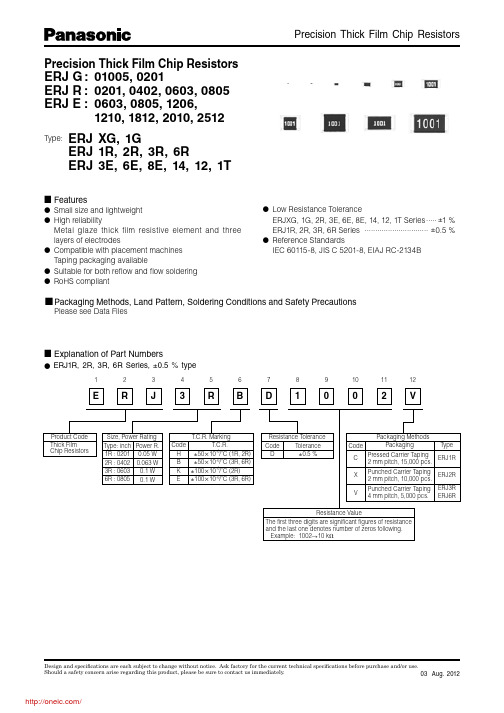
&132+3435#6%7891071112Product Code Thick Film Chip ResistorsSize, Power Rating Type: inch 1R : 02012R : 04023R : 06036R : 0805Power R.0.05 W 0.063 W 0.1 W 0.1 W T.C.R. MarkingT.C.R.Code HBKE±50L 10–6/˚C (1R, 2R) ±50L 10–6/˚C (3R, 6R)±100L 10–6/˚C (2R)±100L 10–6/˚C (3R, 6R)Resistance ValueResistance ToleranceCode D Tolerance ±0.5 %Packaging MethodsCode C X VPressed Carrier Taping2 mm pitch, 15,000 pcs.Punched Carrier Taping2 mm pitch, 10,000 pcs.Punched Carrier Taping 4 mm pitch, 5,000 pcs.ERJ1RERJ2RERJ3R ERJ6RPackagingTypeThe first three digits are significant figures of resistance and the last one denotes number of zeros following. Example: 1002 10 k ?Precision Thick Film Chip Resistors ERJ G : 01005, 0201ERJ R : 0201, 0402, 0603, 0805ERJ E : 0603, 0805, 1206, 1210, 1812, 2010, 2512Type:ERJ XG, 1GERJ 1R, 2R, 3R, 6RERJ 3E, 6E, 8E, 14, 12, 1T■ Features● Small size and lightweight ● High reliabilityMetal glaze thick film resistive element and three layers of electrodes● Compatible with placement machines Taping packaging available ● Suitable for both refl ow and fl ow soldering ● RoHS compliant■ Explanation of Part Numbers● Low Resistance ToleranceERJXG, 1G, 2R, 3E, 6E, 8E, 14, 12, 1T Series .....±1 %ERJ1R, 2R, 3R, 6R Series.............................. ±0.5 %● Reference StandardsIEC 60115-8, JIS C 5201-8, EIAJ RC-2134B● ERJ1R, 2R, 3R, 6R Series, ±0.5 % typePackaging Methods, Land Pattern, Soldering Conditions and Safety PrecautionsPlease see Data Files● ERJXG, 1G, 2R, 3E, 6E, 8E, 14, 12, 1T Series, ±1 % type■ Construction■ Dimensions in mm (not to scale)Protective coatingAlumina substrateElectrode (Inner)Electrode(Between)Thick filmresistive element Electrode (Outer)Type(inch size)Dimensions (mm)Mass (Weight)[g/1000 p cs.]L W a b tERJXG(01005)0.40±0.020.20±0.020.10±0.030.10±0.030.13±0.020.04ERJ1G, 1R(0201)0.60±0.030.30±0.030.10±0.050.15±0.050.23±0.030.15ERJ2R□(0402) 1.00±0.050.50±0.050.20±0.100.25±0.050.35±0.050.8ERJ3R□ERJ3EK(0603)1.60±0.150.80+0.150.30±0.200.30±0.150.45±0.102ERJ6R□ERJ6EN(0805)2.00±0.20 1.25±0.100.40±0.200.40±0.200.60±0.104ERJ8EN(1206) 3.20+0.05 1.60+0.050.50±0.200.50±0.200.60±0.1010ERJ14N(1210) 3.20±0.20 2.50±0.200.50±0.200.50±0.200.60±0.1016ERJ12N(1812) 4.50±0.20 3.20±0.200.50±0.200.50±0.200.60±0.1027ERJ12S(2010) 5.00±0.20 2.50±0.200.60±0.200.60±0.200.60±0.1027ERJ1TN(2512) 6.40±0.20 3.20±0.200.65±0.200.60±0.200.60±0.1045–0.05–0.15–0.20–55 °CAmbient Temperature (°C)20406080100R a t e d L o a d (%)Type (inch size)Power Rating at 70 °C(W)Limiting Element Voltage (1)(V)Maximum Overload Voltage (2)(V)ResistanceTolerance (%)ResistanceRange (Ω)T.C.R.(×10–6/°C)CategoryTemperature Range(°C)ERJ1RH(0201)0.051530±0.5 1 k to 1 M (E24, E96)±50–55 to +125ERJ2RH (0402)0.06350100±0.5100 to 100 k (E24, E96)±50–55 to +125ERJ2RK(0402)0.06350100±0.510 to 97.6102 k to 1 M (E24, E96)±100–55 to +125ERJ3RB(0603)0.150100±0.5100 to 100 k (E24, E96)±50–55 to +125ERJ3RE(0603)0.150100±0.510 to 97.6102 k to 1 M (E24, E96)±100–55 to +125ERJ6RB (0805)0.1150200±0.5100 to 100 k (E24, E96)±50–55 to +125ERJ6RE(0805)0.1150200±0.510 to 97.6102 k to 1 M (E24, E96)±100–55 to +125(1) Rated Continuous Working Voltage (RCWV) shall be de t er m ined from RCWV=√Power Rating × Re s is t ance Values, or Limiting Element Voltagelist e d above, whichever less.(2) O verload (Short-time O verload) Test Voltage (SO TV) shall be de t ermined from SO TV=2.5 (O nly ERJ2RK ±1% =2.0) × Power Rating or max.Over l oad Volt a ge list e d above whichever less.(3) Please contact us when you need a type with a resistance of less than 10 Ω.■ Ratings<±0.5 %>Type (inch size)Power Rating at 70 °C(W)Limiting Element Voltage (1)(V)Maximum Overload Voltage (2)(V)ResistanceTolerance (%)ResistanceRange (Ω)T.C.R.(×10–6/°C)CategoryTemperature Range(°C)ERJXGN(01005)0.0311530±110 to 1 M (E24, E96)<100 Ω : ±300100 Ω < : ±200–55 to +125ERJ1GN(0201)0.052550±110 to 1 M (3)(E24, E96)±200–55 to +125ERJ2RK(0402)0.150100±110 to 1 M (3)(E24, E96)±100–55 to +155ERJ3EK(0603)0.175150±110 to 1 M (E24, E96)±100–55 to +155ERJ6EN (0805)0.125150200±110 to 2.2 M (E24, E96)±100–55 to +155ERJ8EN (1206)0.25200400±110 to 2.2 M (E24, E96)±100–55 to +155ERJ14N (1210)0.5200400±110 to 1 M (E24, E96)±100–55 to +155ERJ12N (1812)0.75200500±110 to 1 M (E24, E96)±100–55 to +155ERJ12S(2010)0.75200500±110 to 1 M (E24, E96)±100–55 to +155ERJ1TN(2512)1200500±110 to 1 M (E24, E96)±100–55 to +155<±1 %>Power Derating CurveFor resistors operated in ambient temperatures above 70 °C, power rating shall be derated in ac c or d ance with the fi gure on the right.分销商库存信息:PANASONICERJ-3EKF2004V ERJ-3EKF1104V ERJ-3EKF6191V ERJ-3EKF1504V ERJ-3EKF1304V ERJ-3EKF1804V ERJ-3EKF1204V ERJ-3EKF1621V ERJ-3EKF2204V ERJ-3EKF1604V ERJ-2RKF4220X ERJ-2RKF6190X ERJ-6ENF2373V ERJ-6ENF2321V ERJ-6ENF2372V ERJ-6ENF2323V ERJ-6ENF2371V ERJ-6ENF23R7V ERJ-6ENF2370V ERJ-6ENF2322V ERJ-1GEF8201C ERJ-1GEF2202C ERJ-1GEF2000C ERJ-1GEF2002C ERJ-1GEF2430C ERJ-1GEF1800C ERJ-1GEF10R0C ERJ-1GEF2001C ERJ-1GEF4701C ERJ-1GEF4322C ERJ-1GEF47R0C ERJ-1GEF2493C ERJ-1GEF1501C ERJ-1GEF3322C ERJ-1GEF33R0C ERJ-1GEF1473C ERJ-1GEF2153C ERJ-1GEF1503C ERJ-1GEF2492C ERJ-1GEF1153C ERJ-1GEF4992C ERJ-1GEF4993C ERJ-1GEF1803C ERJ-1GEF75R0C ERJ-1GEF1583C ERJ-1GEF3093C ERJ-1GEF1102C ERJ-1GEF1202C ERJ-1GEF4702C ERJ-1GEF4021C ERJ-1GEF27R0C ERJ-1GEF3003C ERJ-1GEF63R4C ERJ-1GEF84R5C ERJ-1GEF3011C ERJ-1GEF2872C ERJ-1GEF6653C ERJ-1GEF4990C ERJ-1GEF24R0C ERJ-1GEF39R0C ERJ-1GEF4700C ERJ-1GEF7500C ERJ-1GEF33R2C ERJ-1GEF2802C ERJ-1GEF1502C ERJ-1GEF2003C ERJ-1GEF3000C ERJ-1GEF4301C ERJ-1GEF6491C ERJ-1GEF7151C ERJ-1GEF9761C ERJ-1GEF3012C ERJ-1GEF6342C ERJ-1GEF8253C ERJ-1GEF1212C ERJ-1GEF1201C ERJ-1GEF1500C ERJ-1GEF22R0C ERJ-1GEF2400C ERJ-1GEF2402C ERJ-1GEF5101C ERJ-1GEF5603C ERJ-1GEF68R0C ERJ-1GEF68R1C ERJ-1GEF93R1C ERJ-1GEF1211C ERJ-1GEF5762C ERJ-1GEF1243C ERJ-1GEF2213C ERJ-1GEF16R0C ERJ-1GEF3600C ERJ-1GEF3603C ERJ-1GEF3901C ERJ-1GEF6200C ERJ-1GEF6803C ERJ-1GEF8200C ERJ-1GEF45R3C ERJ-1GEF82R5C ERJ-1GEF2740C ERJ-1GEF3740C ERJ-1GEF7150C ERJ-1GEF1821C ERJ-1GEF1961C ERJ-1GEF8061C ERJ-1GEF1622C ERJ-1GEF4642C ERJ-1GEF5622C ERJ-1GEF1333C ERJ-1GEF3653C ERJ-1GEF4223C ERJ-1GEF7501C ERJ-1GEF1303C ERJ-1GEF2702C ERJ-1GEF3002C ERJ-1GEF3301C ERJ-1GEF3601C ERJ-1GEF51R0C ERJ-1GEF56R0C ERJ-1GEF5601C ERJ-1GEF5602C ERJ-1GEF6203C ERJ-1GEF22R6C ERJ-1GEF24R9C ERJ-1GEF57R6C ERJ-1GEF1270C ERJ-1GEF1960C ERJ-1GEF2940C ERJ-1GEF3320C ERJ-1GEF4320C。
FR3D-T3中文资料
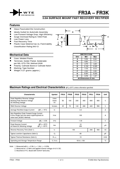
FR3A – FR3K3.0A SURFACE MOUNT FAST RECOVERY RECTIFIERCharacteristicSymbol FR3AFR3BFR3DFR3GFR3JFR3KUnitPeak Repetitive Reverse Voltage Working Peak Reverse Voltage DC Blocking Voltage V RRMV RWM V R 50100200400600800V RMS Reverse VoltageV R(RMS)3570140280420560V Average Rectified Output Current @T L = 75°C I O 3.0A Non-Repetitive Peak Forward Surge Current 8.3ms Single half sine-wave superimposed on rated load (JEDEC Method)I FSM 100A Forward Voltage @I F = 3.0A V FM 1.30V Peak Reverse Current @T A = 25°C At Rated DC Blocking Voltage @T A = 125°C I RM 10350µAReverse Recovery Time (Note 1)t rr 150250500nS Typical Junction Capacitance (Note 2)C j 60pF Typical Thermal Resistance (Note 3)R JL 15K/W Operating and Storage Temperature RangeT j, T STG-50 to +150°CNote: 1. Measured with I F = 0.5A, I R = 1.0A, I rr = 0.25A,2. Measured at 1.0 MHz and applied reverse voltage of 4.0 V DC.3. Mounted on P .C. Board with 8.0mm 2 land area.W T EWER SEMICONDUCTORS00.51.0255075100125150175I ,A V E R A G E F O R W A R D C U R R E N T (A )(A V )T ,LEAD TEMPERATURE (°C)Fig.1Forward Current Derating CurveL 1.52.02.53.00.010.11.0100.40.81.21.6I I N S T A N T A N E O U S F O R W A R D C U R R E N T (A )F ,V ,INSTANTANEOUS FORWARD VOLTAGE (V)Fig.2Typical Forward CharacteristicsF 020110100I ,P E A K F O R W A R D S U R G E C U R R E N T (A )F S M NUMBER OF CYCLES AT 60HzFig.3ForwardSurge Current Derating Curve40608010010NIΩSet time base for 10ns/cm+0.5A0A -0.25A-1.0ANotes:1.Rise Time =7.0ns max.Input Impedance =1.0M ,22pF.2.Rise Time =10ns max.Input Impedance =50.ΩΩFig.5Reverse Recovery Time Characteristic and Test Circuit0.11.010100100020406080100120140I ,I N S T A N T A N E O U S R E V E R S E C U R R E N T (µA )R PERCENT OF RATED PEAK REVERSE VOLTAGE (%)Fig.4Typical Reverse CharacteristicsORDERING INFORMATIONProduct No.!Package TypeShipping QuantityFR3A-T1SMC 500/Tape & ReelFR3A-T3SMC3000/Tape & Reel FR3B-T1SMC 500/Tape & Reel FR3B-T3SMC 3000/Tape & Reel FR3D-T1SMC 500/Tape & Reel FR3D-T3SMC 3000/Tape & Reel FR3G-T1SMC 500/Tape & Reel FR3G-T3SMC 3000/Tape & Reel FR3J-T1SMC 500/Tape & Reel FR3J-T3SMC 3000/Tape & Reel FR3K-T1SMC 500/Tape & Reel FR3K-T3SMC3000/Tape & ReelProducts listed in bold are WTE Preferred devices.!T1 suffix refers to a 7” reel. T3 suffix refers to a 13” reel.Shipping quantity given is for minimum packing quantity only. For minimum order quantity, please consult the Sales Department.RECOMMENDED FOOTPRINTinches(mm)Won-Top Electronics Co., Ltd (WTE) has checked all information carefully and believes it to be correct and accurate. However, WTE cannot assume any responsibility for inaccuracies. Furthermore, this information does not give the purchaser of semiconductor devices any license under patent rights to manufacturer. WTE reserves the right to change any or all information herein without further notice.WARNING : DO NOT USE IN LIFE SUPPORT EQUIPMENT. WTE power semiconductor products are not authorized for use as critical components in life support devices or systems without the express written approval.We power your everyday.Won-Top Electronics Co., Ltd.No. 44 Yu Kang North 3rd Road, Chine Chen Dist., Kaohsiung, Taiwan Phone: 886-7-822-5408 or 886-7-822-5410Fax: 886-7-822-5417Email: sales@Internet: 。
ER3M中文资料
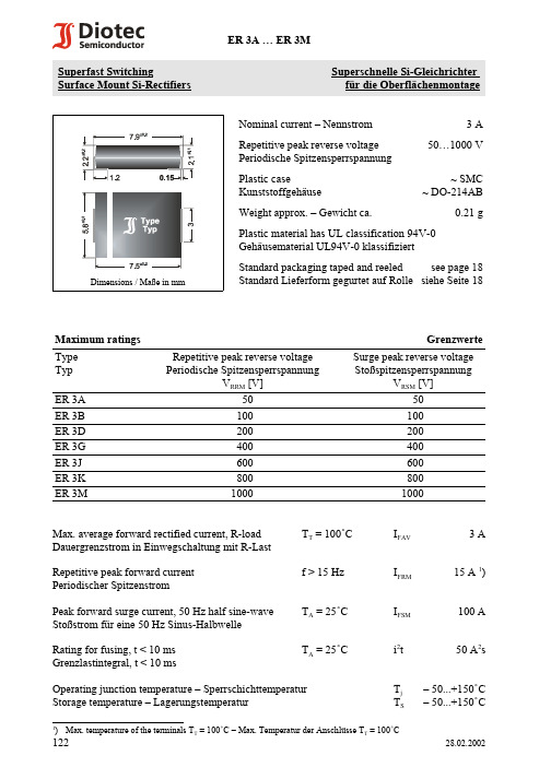
1)Max. temperature of the terminals T T = 100/C – Max. Temperatur der Anschlüsse T T = 100/C12228.02.2002Superfast SwitchingSuperschnelle Si-Gleichrichter Surface Mount Si-Rectifiersfür die OberflächenmontageNominal current – Nennstrom 3 ARepetitive peak reverse voltage 50…1000 V Periodische Spitzensperrspannung Plastic case~ SMC Kunststoffgehäuse~ DO-214ABWeight approx. – Gewicht ca.0.21 gPlastic material has UL classification 94V-0Gehäusematerial UL94V-0 klassifiziertDimensions / Maße in mmStandard packaging taped and reeled see page 18Standard Lieferform gegurtet auf Rolle siehe Seite 18Maximum ratings GrenzwerteType Typ Repetitive peak reverse voltage Periodische SpitzensperrspannungV RRM [V]Surge peak reverse voltage StoßspitzensperrspannungV RSM [V]ER 3A 5050ER 3B 100100ER 3D 200200ER 3G 400400ER 3J 600600ER 3K 800800ER 3M10001000Max. average forward rectified current, R-load T T = 100/C I FAV 3 A Dauergrenzstrom in Einwegschaltung mit R-Last Repetitive peak forward current f > 15 Hz I FRM 15 A 1)Periodischer SpitzenstromPeak forward surge current, 50 Hz half sine-wave T A = 25/C I FSM 100 A Stoßstrom für eine 50 Hz Sinus-Halbwelle Rating for fusing, t < 10 ms T A = 25/Ci 2t 50 A 2s Grenzlastintegral, t < 10 msOperating junction temperature – Sperrschichttemperatur T j – 50...+150/C Storage temperature – LagerungstemperaturT S– 50...+150/C1)I F = 0.5 A through/über I R = 1 A to/auf I R = 0.25 A2)Mounted on P.C. board with 50 mm 2 copper pads at each terminalMontage auf Leiterplatte mit 50 mm 2 Kupferbelag (Lötpad) an jedem Anschluß12328.02.2002Characteristics KennwerteType TypReverse recovery time Sperrverzugszeitt rr [ns] 1)Forward voltage Durchlaßspannung V F [V] at / bei I F [A]ER 3A ... ER 3D < 35< 1.03ER 3G< 35< 1.253ER 3J ... ER 3M< 75< 1.73Leakage current T j = 25/C V R = V RRM I R < 5 :A SperrstromT j = 100/CV R = V RRM I R < 300 :A Thermal resistance junction to ambient airR thA < 50 K/W 2)Wärmewiderstand Sperrschicht – umgebende Luft Thermal resistance junction to terminal R thT< 10 K/WWärmewiderstand Sperrschicht – Anschluß。
美国Eaton公司PDG23G0035TFFN型号的产品说明书
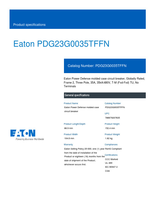
Eaton PDG23G0035TFFNEaton Power Defense molded case circuit breaker, Globally Rated, Frame 2, Three Pole, 35A, 35kA/480V, T-M (Fxd-Fxd) TU, No TerminalsEaton Power Defense molded case circuit breakerPDG23G0035TFFN 78667920763588.9 mm 152.4 mm 104.6 mm 1.82 kg Eaton Selling Policy 25-000, one (1) year from the date of installation of theProduct or eighteen (18) months from thedate of shipment of the Product,whichever occurs first.RoHS Compliant CCC MarkedUL 489IEC 60947-2CSAProduct NameCatalog Number UPCProduct Length/Depth Product Height Product Width Product Weight WarrantyCompliancesCertifications35 AComplete breaker 2Three-polePD2 Global Class A T-M (Fxd-Fxd) TU600 Vac600 VNo Terminals35 kAIC at 480 Vac 10 kAIC Icu @250 Vdc 18 kAIC @600V (UL/CSA)55 kAIC Icu/ 55 kAIC Ics/ 121 kAIC Icm @240V (IEC) 25 kAIC Icu/ 20 kAIC Ics/ 52.5 kAIC Icm @480V Brazil (IEC) 36 kAIC Icu/ 36 kAIC Ics/ 75.6 kAIC Icm @380-415V (IEC) 10 kAIC Icu @125 Vdc 35 kAIC @480V (UL) 65 kAIC @240V (UL)20 kAIC Icu/ 15/13 kAIC Ics/ 42 kAIC Icm @525V South Africa (IEC)30 kAIC Icu/ 22.5 kAIC Ics/ 63 kAIC Icm @440V (IEC) 8 kAIC Icu/ 4 kAIC Ics/ 16.8 kAIC Icm @690V (IEC)Eaton Power Defense MCCB PDG23G0035TFFN 3D drawing Consulting application guide - molded case circuit breakers Amperage Rating Circuit breaker frame type Frame Number of poles Circuit breaker type Class Trip Type Voltage rating Voltage rating - max Terminals Interrupt rating Interrupt rating range 3D CAD drawing packageApplication notesBrochuresPower Defense technical selling bookletPower Defense brochurePower Defense molded case circuit breaker selection posterPower Defense molded case circuit breakers - Frame 2 product aidCatalogsMolded case circuit breakers catalogCertification reportsPDG4 CB reportPDG4 CCC certificationPDG2 CB reportPower Defense Declaration concerning California’s Proposition 65EU Declaration of Conformity - Power Defense molded case circuit breakersInstallation instructionsPower Defense Frame 2 tunnel terminal kits - PDG2X1TA225K instructions- IL012239EN H01Power Defense Frame 2 terminal kit - PDG2X3(2)(4)TA225RF instructions - IL012245EN H01Power Defense Frame 2 tunnel terminal (aluminum), 150A, 3 pole instructions - IL012238EN H03Power Defense Frame 2 terminal kit - PDG2X3(2)(4)TA150RF instructions - IL012244EN H01Power Defense Frame 2 locking devices and handle block instructions - IL012149ENPower Defense Frame 2 clamp terminal (steel), 20A, 3 pole instructions - IL012246EN H03Power Defense Frame 2 box terminal (steel), 100A, 3 pole instructions - IL012234EN H03Power Defense Frame 2 tunnel terminal (aluminum), 100A, 3 pole instructions - IL012237EN H03Power Defense Frame 2 shunt trip UVR instructions - IL012130EN Power Defense Frame 2 box terminal (aluminum), 225A, 3 pole instructions - IL012235EN H03Power Defense Frame 2 global terminal shield, 3 pole - IL012330EN Power Defense Frame 2/3/4/5/6 voltage neutral sensor module wiring instructions – IL012316ENPower Defense Frame 1 IEC and Frame 2 Rotary Mechanism with NFPA Handle Attachment Instructions (IL012260EN).pdfPower Defense Frame 2 tunnel terminal (aluminum), 50A, 3 pole instructions - IL012236EN H03Power Defense Frame 1-2-3-4 IP door barrier assembly instructions -IL012278ENPower Defense Frame 2 PDG2 and PDC(E)9 breaker instructions -IL012106ENPower Defense Frame 2 multi wire connector kit -PDG2X3(2)(4)TA2256W instructions - IL012242EN H01Power Defense Frame 2 handle mech variable depth rotary handle instructions - IL012136ENPower Defense Frame 2 handle mech direct rotary handle instructions - IL012134ENPower Defense Frame 2 Direct Rotary Handle Assy With Interlock Version Instructions (IL012138EN).pdfPower Defense Frame 2 screw terminal_end cap kit, 225A, 3 pole instructions - IL012258EN H01Power Defense Frame 2 multi wire connector kit -PDG2X3(2)(4)TA2253W instructions - IL012243EN H01Installation videosPower Defense Frame 2 TMTU Aux, Alarm, ST and UVR Animated Instructions.rhPower Defense Frame 2 Bell Alarm with PXR Animated Instructions.pdf.rh Power Defense Frame 2 withTMTU, Shunt Trip_UVR Animated Instructions.rhPower Defense Frame 2 Handle Mech Variable Depth Rotary Handle Animated Instructions.rhPower Defense Frame 2 Locking Devices and Handle Block Animated Instructions.pdf.rhMultimediaPower Defense Frame 3 Variable Depth Rotary Handle Mechanism Installation How-To VideoPower Defense Frame 2 Variable Depth Rotary Handle Mechanism Installation How-To VideoPower Defense Frame 2 Aux, Alarm, Shunt Trip, and UVR How-To Video Power Defense Frame 2 Direct Rotary Handle Mechanism Installation How-To VideoEaton Power Defense for superior arc flash safetyPower Defense molded case circuit breakersPower Defense Frame 5 Trip Unit How-To VideoPower Defense Frame 6 Trip Unit How-To VideoPower Defense BreakersSpecifications and datasheetsEaton Specification Sheet - PDG23G0035TFFNTime/current curvesEaton Corporation plc Eaton House30 Pembroke Road Dublin 4, Ireland © 2023 Eaton. All Rights Reserved. Eaton is a registered trademark.All other trademarks areproperty of their respectiveowners./socialmediaPower Defense time current curve Frame 2 - PD2Intelligent circuit protection yields space savingsMolded case and low-voltage power circuit breaker health Single and double break MCCB performance revisited Making a better machineSafer by design: arc energy reduction techniques Molded case and low-voltage breaker healthWhite papers。
YBX3三相异步电动机样本单行本

- .X X电动机股份X X技术文件YBX3系列隔爆型高效率三相异步电动机(机座号80~355)产品样本XX电动机股份XX发布YBX3系列隔爆型高效率三相异步电动机(机座号80~355)样本1 概述YBX3系列隔爆型高效率三相异步电动机是我公司开发设计的全封闭自扇冷式高效率三相异步电动机。
效率指标符合GB18613-2006《中小型三相异步电动机能效限定值及能效等级》中的“电动机节能评价值”中的1级效率的规定,并满足美国能源法规定的电动机应符合EPACT效率指标要求的规定。
本系列电动机符合国家标准GB 3836.1《爆炸性气体环境用电气设备第1部分:通用要求》和GB3836.2《爆炸性气体环境用电气设备第2部分:隔爆型“d”》的规定。
本系列电动机制成隔爆型,适用于爆炸性气体环境中机械设备的电力驱动。
分为I类和II类,I类:煤矿用电气设备,防爆标志为ExdI;II类:除煤矿外的其它爆炸性气体环境,防爆标志为ExdIIAT(1-4),ExdIIBT(1-4),ExdIICT(1-4),温度组别为T1、T2、T3、T4。
本系列电动机机座号围为H80~H355,功率等级和安装尺寸符合GB/T4772.1/IEC 60072-1和GB/T4772.2/ IEC 60072-2标准的规定。
2 产品特点YBX3系列电动机整体外观见图1。
图1 整体外观图产品主要有以下特点:a) 电动机主接线盒位于机座的顶部,可以左右旋转满足用户不同出线方式的要求。
b)机座号H160及以上电机,可以根据用户需要提供定子测温装置、轴承测温装置、加热器、注排油装置。
c) 接线盒、机座、端盖和风罩的外形美观、样式新颖,并且有利于降噪和通风。
d) 电动机采用F级绝缘系统,温升按B级考核,从而延长电机的使用寿命。
e) 电动机工作制为S1,冷却方式为IC411,外壳防护等级为IP55。
f) 适用于各种应用场合,如:“W”、“TH”、“WTH”、“F1”、“F2”、“WF1”及“WF2”,其中:W为户外防轻腐蚀;TH为湿热;WTH为户外湿热;F1为户防中等防腐;F2为户防强腐蚀;WF1为户外防中等腐蚀;WF2为户外防强腐蚀。
DWYER INSTRUMENTS WE33 自动三路三环钢球控制阀说明说明书
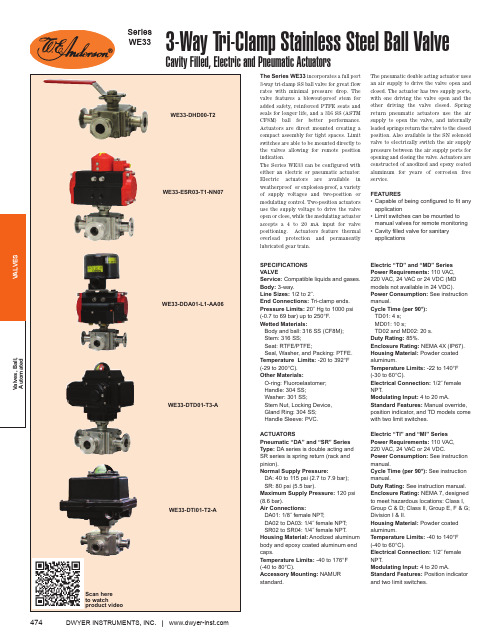
DWYER INSTRUMENTS, INC.| 474The Series WE33incorporates a full port 3-way tri-clamp SS ball valve for great flow rates with minimal pressure drop. The valve features a blowout-proof stem for added safety, reinforced PTFE seats and seals for longer life, and a 316 SS (ASTM CF8M) ball for better performance.Actuators are direct mounted creating a compact assembly for tight spaces. Limit switches are able to be mounted directly to the valves allowing for remote position indication.The Series WE33 can be configured with either an electric or pneumatic actuator.Electric actuators are available in weatherproof or explosion-proof, a variety of supply voltages and two-position or modulating control. Two-position actuators use the supply voltage to drive the valve open or close, while the modulating actuator accepts a 4 to 20 mA input for valve positioning. Actuators feature thermal overload protection and permanently lubricated gear train.The pneumatic double acting actuator uses an air supply to drive the valve open and closed. The actuator has two supply ports,with one driving the valve open and the other driving the valve closed. Spring return pneumatic actuators use the air supply to open the valve, and internally loaded springs return the valve to the closed position. Also available is the SN solenoid valve to electrically switch the air supply pressure between the air supply ports for opening and closing the valve. Actuators are constructed of anodized and epoxy coated aluminum for years of corrosion free service.FEATURES• Capable of being configured to fit any application• Limit switches can be mounted to manual valves for remote monitoring • Cavity filled valve for sanitary applicationsSPECIFICATIONSVALVE Service:Compatible liquids and gases.Body: 3-way.Line Sizes:1/2 to 2˝.End Connections: Tri-clamp ends.Pressure Limits:20˝ Hg to 1000 psi(-0.7 to 69 bar) up to 250°F.Wetted Materials:Body and ball: 316 SS (CF8M);Stem: 316 SS;Seat: RTFE/PTFE;Seal, Washer, and Packing: PTFE.Temperature Limits:-20 to 392°F(-29 to 200°C).Other Materials:O-ring: Fluoroelastomer;Handle: 304 SS;Washer: 301 SS;Stem Nut, Locking Device,Gland Ring: 304 SS;Handle Sleeve: PVC.ACTUATORSPneumatic “DA” and “SR” Series Type:DA series is double acting and SR series is spring return (rack and pinion).Normal Supply Pressure:DA: 40 to 115 psi (2.7 to 7.9 bar);SR: 80 psi (5.5 bar).Maximum Supply Pressure:120 psi (8.6 bar).Air Connections:DA01: 1/8˝ female NPT;DA02 to DA03: 1/4˝ female NPT;SR02 to SR04: 1/4˝ female NPT.Housing Material:Anodized aluminum body and epoxy coated aluminum end caps.Temperature Limits:-40 to 176°F (-40 to 80°C).Accessory Mounting:NAMUR standard.Electric “TD” and “MD” Series Power Requirements: 110 VAC, 220 VAC, 24 VAC or 24 VDC (MD models not available in 24 VDC).Power Consumption:See instruction manual.Cycle Time (per 90°): TD01: 4 s;MD01: 10 s; TD02 and MD02: 20 s.Duty Rating:85%.Enclosure Rating:NEMA 4X (IP67).Housing Material:Powder coated aluminum.Temperature Limits: -22 to 140°F (-30 to 60°C).Electrical Connection:1/2˝ female NPT.Modulating Input:4 to 20 mA.Standard Features:Manual override,position indicator, and TD models come with two limit switches. Electric “TI” and “MI” Series Power Requirements: 110 VAC, 220 VAC, 24 VAC or 24 VDC.Power Consumption:See instruction manual.Cycle Time (per 90°): See instruction manual.Duty Rating: See instruction manual.Enclosure Rating:NEMA 7, designed to meet hazardous locations: Class I,Group C & D; Class II, Group E, F & G;Division I & II.Housing Material:Powder coated aluminum.Temperature Limits:-40 to 140°F (-40 to 60°C).Electrical Connection:1/2˝ female NPT.Modulating Input:4 to 20 mA.Standard Features:Position indicator and two limit switches.3-Way Tri-Clamp Stainless Steel Ball ValveCavity Filled, Electric and Pneumatic ActuatorsSeries WE33Scan here475Flow PathsCONTACT US | U.S. 219/879-8000 | U.K. (+44) (0)1494-461707| A.U. (+61) (0) 2 4272 2055| China +852-********ACCESSORIESR2-2120,Air RegulatorAFR2-2, Instrument Air Filter Regulator VB-01, Volume Booster。
- 1、下载文档前请自行甄别文档内容的完整性,平台不提供额外的编辑、内容补充、找答案等附加服务。
- 2、"仅部分预览"的文档,不可在线预览部分如存在完整性等问题,可反馈申请退款(可完整预览的文档不适用该条件!)。
- 3、如文档侵犯您的权益,请联系客服反馈,我们会尽快为您处理(人工客服工作时间:9:00-18:30)。
ER3A – ER3J
3.0A SURFACE MOUNT SUPER FAST RECTIFIER
Characteristic Symbol ER3A ER3B ER3C ER3D ER3E ER3G ER3J Unit
Peak Repetitive Reverse Voltage Working Peak Reverse Voltage DC Blocking Voltage V RRM
V RWM
V R
50100150200300400600V
RMS Reverse Voltage V R(RMS)3570105140210280420V Average Rectified Output Current @T L = 75°C I O 3.0A Non-Repetitive Peak Forward Surge Current
8.3ms Single half sine-wave superimposed on
rated load (JEDEC Method)
I FSM100A Forward Voltage @I F = 3.0A V FM0.95 1.25 1.7V
Peak Reverse Current @T A = 25°C At Rated DC Blocking Voltage @T A = 100°C I RM
5.0
500
µA
Reverse Recovery Time (Note 1)t rr35nS Typical Junction Capacitance (Note 2)C j45pF Typical Thermal Resistance (Note 3)R JL16K/W Operating and Storage Temperature Range T j, T STG-65 to +150°C
Note: 1. Measured with I F = 0.5A, I R = 1.0A, I rr = 0.25A,
2. Measured at 1.0 MHz and applied reverse voltage of 4.0 V DC.
3. Mounted on P.C. Board with 8.0mm2 land area.
WTE
0.01
0.1
1.0
10
100
0.6
1.0 1.4 1.8
V ,INSTANTANEOUS FORWARD VOLTAGE (V)
Fig.2Typical Forward Characteristics
F I ,I N S T A N T A N E O U S F O R W A R D C U R R E N T (A )
F 10
100
2001
10
100
I ,P E A K F O R W A R D S U R G E C U R R E N T (A )
F S M NUMBER OF CYCLES AT 60Hz Fig.3Peak Forward Surge Current
Set time base for 5/10ns/cm
+0.5A
0A -0.25A
-1.0A
Notes:
1.Rise Time =7.0ns max.Input Impedance =1.0M ,22pF.
2.Rise Time =10ns max.Input Impedance =50.
ΩΩFig.5Reverse Recovery Time Characteristic and Test Circuit
10100
1000
1
10
100
C ,C A P A C I T A N C E (p F )
j V ,REVERSE VOLTAGE (V)Fig.4Typical Junction Capacitance
R 01
2
340
25
50
75
100
125
150
175
I ,A V E R A G E F W D R E C T I F I E D C U R R E N T (A )
(A V )T ,LEAD TEMPERATURE ( C)Fig.1Forward Current Derating Curve
L °
ORDERING INFORMATION
Product No.!
Package Type
Shipping Quantity
ER3A-T1SMC 500/Tape &
Reel ER3A-T3
SMC 3000/Tape & Reel ER3B-T1SMC 500/Tape & Reel ER3B-T3SMC 3000/Tape & Reel ER3C-T1SMC 500/Tape & Reel ER3C-T3SMC 3000/Tape & Reel ER3D-T1SMC 500/Tape & Reel ER3D-T3SMC 3000/Tape & Reel ER3E-T1SMC 500/Tape & Reel ER3E-T3SMC 3000/Tape & Reel ER3G-T1SMC 500/Tape & Reel ER3G-T3SMC 3000/Tape & Reel ER3J-T1SMC 500/Tape & Reel ER3J-T3
SMC
3000/Tape & Reel
Products listed in bold are WTE Preferred devices.
!
T1 suffix refers to a 7” reel. T3 suffix refers to a 13” reel.
Shipping quantity given is for minimum packing quantity only. For minimum order quantity, please consult the Sales Department.
RECOMMENDED FOOTPRINT
inches(mm)
Won-Top Electronics Co., Ltd (WTE) has checked all information carefully and believes it to be correct and accurate. However, WTE cannot assume any responsibility for inaccuracies. Furthermore, this information does not give the purchaser of semiconductor devices any license under patent rights to manufacturer. WTE reserves the right to change any or all information herein without further notice.
WARNING : DO NOT USE IN LIFE SUPPORT EQUIPMENT. WTE power semiconductor products are not authorized for use as critical components in life support devices or systems without the express written approval.
We power your everyday.
Won-Top Electronics Co., Ltd.
No. 44 Yu Kang North 3rd Road, Chine Chen Dist., Kaohsiung, Taiwan Phone: 886-7-822-5408 or 886-7-822-5410Fax: 886-7-822-5417
Email: sales@
Internet: 。
