1N4390中文资料
1N系列二极管
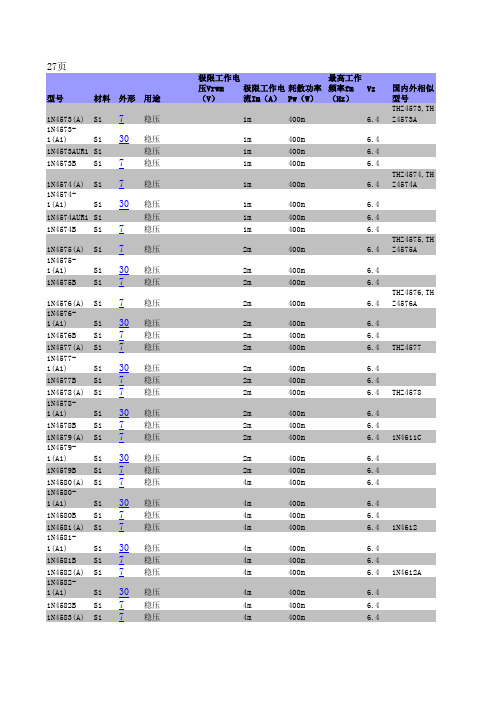
250μ 250μ 250μ
250μ 250μ
250μ 250μ 250μ
250μ 250μ
250μ 250μ 250μ
250μ 250μ
250μ 250μ 250μ
250μ
400m
6.4
2m
400m
6.4
4m
400m
6.4
4m
400m
4m
400m
4m
400m
6.4 6.4 6.4 1N4612
4m
400m
4m
400m
4m
400m
6.4 6.4 6.4 1N4612A
4m
400m
6.4
4m
400m
6.4
4m
400m
6.4
1N4583-
1(A1)
Si 30 稳压
1N4583B Si 7 稳压
)
Si 7
稳压 稳压
1N4616DUR1 Si
1N4617(-1) Si 7
1N4617C(C1
)
Si 7
稳压 稳压
稳压
1N4617CUR1 Si
1N4617D(D1
)
Si 7
稳压 稳压
1N4617DUR1 Si
1N4618(-1) Si 7
1N4618C(C1
)
Si 7
稳压 稳压
稳压
4m 4m 4m
3.6 3.6
3.6 3.6 3.9 MZ4622
3.9 3.9
3.9 3.9 4.3 MZ4623
3N60资料
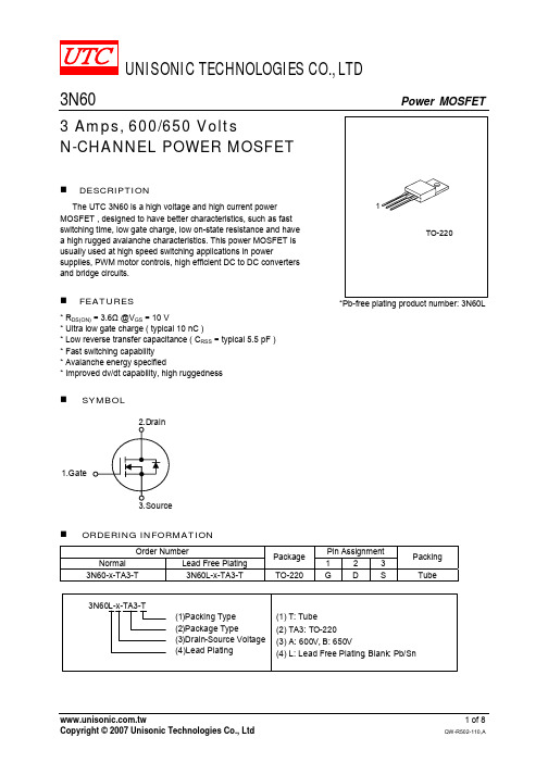
UNISONIC TECHNOLOGIES CO., LTD3N60 Power MOSFET3 Amps, 600/650 VoltsN-CHANNEL POWER MOSFETDESCRIPTIONThe UTC 3N60 is a high voltage and high current power MOSFET , designed to have better characteristics, such as fast switching time, low gate charge, low on-state resistance and have a high rugged avalanche characteristics. This power MOSFET is usually used at high speed switching applications in powersupplies, PWM motor controls, high efficient DC to DC converters and bridge circuits.FEATURES* R DS(ON)= 3.6Ω @V GS = 10 V* Ultra low gate charge ( typical 10 nC )* Low reverse transfer capacitance ( C RSS = typical 5.5 pF ) * Fast switching capability * Avalanche energy specified* Improved dv/dt capability, high ruggednessSYMBOL1.Gate*Pb-free plating product number: 3N60LORDERING INFORMATIONOrder NumberPin AssignmentNormal Lead Free Plating Package1 2 3Packing3N60-x-TA3-T 3N60L-x-TA3-TTO-220 G D S TubeABSOLUTE MAXIMUM RATINGS (T C = 25℃, unless otherwise specified)PARAMETER SYMBOL RATINGS UNIT3N60-A 600 VDrain-Source Voltage 3N60-B V DSS650 VGate-Source Voltage V GSS ±30 V Avalanche Current - (Note 1) I AR 3.0 AT C = 25°C 3.0 AContinuous Drain Current T C = 100°C I D1.9 APulsed Drain Current, T P Limited by T JMAX - (Note 1) I DM 12 A Avalanche Energy, Single Pulsed (Note 2) E AS 200 mJ Avalanche Energy, Repetitive, Limited by T JMAX E AR 7.5 mJ Peak Diode Recovery dv/dt (Note 3) dv/dt 4.5 V/ns Power Dissipation P D 75 W Junction Temperature T J +150 Storage Temperature T STG -55 ~ +150Note: Absolute maximum ratings are those values beyond which the device could be permanently damaged.Absolute maximum ratings are stress ratings only and functional device operation is not implied.THERMAL DATAPARAMETER SYMBOL TYP MAX UNITJunction-to-Case θJC 1.67 °C/W Junction-to-Ambient θJA 62.5 °C/WELECTRICAL CHARACTERISTICS (T C =25℃, unless otherwise specified)PARAMETER SYMBOL TEST CONDITIONS MIN TYP MAX UNIT Off Characteristics3N60-A 600 VDrain-Source Breakdown Voltage 3N60-B BV DSS V GS = 0 V, I D = 250 µA650 VV DS = 600 V, V GS = 0 V 10µADrain-Source Leakage Current I DSSV DS = 480 V, T C = 125°C 100µAForward V GS = 30 V, V DS = 0 V 100nAGate-Source Leakage Current Reverse I GSSV GS = -30 V, V DS = 0 V -100nABreakdown Voltage TemperatureCoefficientBV DSS /△T J I D = 250 µA, Referenced to 25°C 0.6 V/On Characteristics Gate Threshold Voltage V GS(TH) V DS = V GS , I D = 250 µA 2.0 4.0V Drain-Source On-State Resistance R DS(ON) V GS = 10 V, I D = 1.5A 2.8 3.6ΩDynamic Characteristics Input Capacitance C ISS 350 450pFOutput Capacitance C OSS 50 65pFReverse Transfer Capacitance C RSSV DS = 25 V, V GS = 0 V, f = 1MHz 5.5 7.5pF Switching Characteristics Turn-On Delay Time t D(ON) 10 30ns Turn-On Rise Time t R 30 70ns Turn-Off Delay Time t D(OFF) 20 50nsTurn-Off Fall Time t FV DD = 300V, I D = 3.0 A, R G = 25Ω(Note 4, 5) 30 70ns Total Gate Charge Q G 10 13nCGate-Source Charge Q GS 2.7 nCGate-Drain Charge Q DDV DS = 480V,I D = 3.0A, V GS = 10 V(Note 4, 5)4.9 nCELECTRICAL CHARACTERISTICS(Cont.)PARAMETER SYMBOL TEST CONDITIONS MIN TYP MAX UNITSource- Drain Diode Ratings and Characteristics Drain-Source Diode Forward Voltage V SD V GS = 0 V, I S = 3.0 A 1.4VMaximum Continuous Drain-SourceDiode Forward CurrentI S 3.0AMaximum Pulsed Drain-Source DiodeForward CurrentI SM 12AReverse Recovery Time t RR 210 ns Reverse Recovery Charge Q RR V GS = 0 V, I S = 3.0 A,dI F /dt = 100 A/µs (Note 4) 1.2 µCNotes: 1. Repetitive Rating : Pulse width limited by T J2. L = 40mH, I AS =3.0A, V DD = 50V, R G = 25 Ω, Starting T J = 25°C 3. I SD ≤ 3.0A, di/dt ≤200A/µs, V DD ≤ BV DSS , Starting T J = 25°C4. Pulse Test: Pulse width ≤ 300µs, Duty cycle ≤ 2%5. Essentially independent of operating temperatureTEST CIRCUITS AND WAVEFORMSV DDV GS (Driver)I SD (D.U.T.)Body DiodeForward Voltage DropV DS(D.U.T.)Fig. 1A Peak Diode Recovery dv/dt Test CircuitFig. 1B Peak Diode Recovery dv/dt WaveformsTEST CIRCUITS AND WAVEFORMS (Cont.)R LDDV DS90%10%V GStFig. 2A Switching Test Circuit Fig. 2B Switching WaveformsFig. 3A Gate Charge Test CircuitFig. 3B Gate Charge Waveform10VLV DDI ASFig. 4A Unclamped Inductive Switching Test Circuit Fig. 4B Unclamped Inductive Switching WaveformsTYPICAL CHARACTERISTICSD r a i n -S o u r c e B r e a k d o w n V o l t a g e , B V D S S (N o r m a l i z e d )Junction Temperature , T J (℃)1.21.11.00.90.8Breakdown Voltage Variation vs .Junction Temperature-100D r a i n -S o u r c e O n -R e s i s t a n c e , R D S (O N ) (N o r m a l i z e d )Junction Temperature , T J (℃)-50502001001503.002.01.00.50.01.52.5On-Resistance V ariation vs.Junction Temperature1010.1Drain -Source Voltage , V DS (V)D r a i n C u r r e n t , I D (A )1001011000Maximum Safe Operating AreaD r a i n C u r r e nt , I D (A )Case Temperature , T C (℃)75100012550251.01.52.02.53.0Maximum Drain Current vs .Case Temperature0.5150101Drain-to-Source Voltage , V DS (V)D r a i n C u r r e n t , I D (A )On-State Characteristics0.1Gate-Source Voltage , V GS (V)D r a i n C u r r e n t , I D (A )Transfer Characteristics1010.1TYPICAL CHARACTERISTICS(Cont.)D r a i n -S o u r c e O n -R e s i s t a n c e , R D S (O N ) (Ω)Drain Current , I D (A)12456On-Resistance Variation vs .Drain Current and Gate Voltage310.10.2Source-Drain Voltage , V SD (V)R e v e r s e D r a i n C u r r e n t , I D R (A )On State Current vs.Allowable Case Temperature 1.80.40.60.81.01.2 1.61.4106000Drain-SourceVoltage , V DS (V)C a p a c i t a n c e (p F )Capacitance Characteristics(Non-Repetitive )G a t e -S o u r c e V o l t a g e , V G S (V )Total Gate Charge , Q G (nC)26108101246420Gate Charge CharacteristicsT h e r m a l R e s p o n s e , θJ C (t )101010101010101Square Wave Pulse Duration , t 1(sec)Transient Thermal Response Curve。
Z0109NN,135中文资料(nxp)中文数据手册「EasyDatasheet - 矽搜」
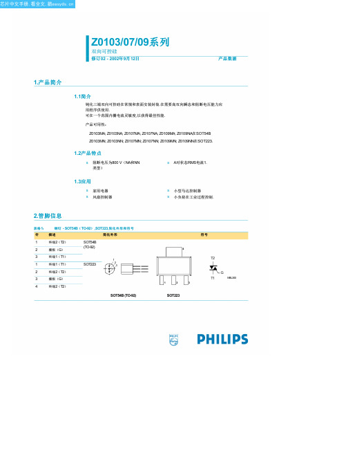
Z0103MA/MN/NA/NN
Z0107MA/MN/NA/NN
Z0109MA/MN/NA/NN
IH
防护持电流
Z0103MA/MN/NA/NN
Z0107MA/MN/NA/NN
Z0109MA/MN/NA/NN
VT
通态电压
VGT
门极触发电压
ID
动态特性
dV D/dt
dV com/dt
断态泄漏电流
崛起临界率 断态电压
Min Max 单元
-
600 V
-
800 V
-
600 V
-
800 V
-
8
A
-
8.5
A
-
1
A
-
1
A
-
0.35 A2s
-
20
A/µs
-
1.0
A
-
2.0
W
-
0.1
W
40 +150 °C
40 +125 °C
芯片中文手册,看全文,戳 飞利浦半导体
Z0103/07/09系列
双向可控硅
1.6
Ptot
1.2产品特点
s 阻断电压为800 V(NA和NN
类型)
s A对状态RMS电流1.
1.3应用
s 家用电器 s 风扇控制器
s 小型马达控制器 s 小负荷在工业过程控制.
2.管脚信息
表格 1: 钢钉 - SOT54B( TO-92) ,SOT223,简化外形和符号
针
描述
简化外形
1
终端2(T2)
2
栅极(G)
点SOT223
从交界处领导热电阻
PJ2N9013中文资料

TO-92
SOT-23
ABSOLUTE MAXIMUM RATINGS (Ta= 25 °C)
Rating Collector Base Voltage Collector Emitter Voltage Emitter Base Voltage Collector Current Collector Dissipation Junction Temperature Storage Temperature Symbol VCBO VCEO VEBO Ic Pc Tj Tstg Value 40 20 5 500 625 150 -55 ~150 Uint V V V A W °C °C
P in : 1. Emitter 2. Base 3. Collector P in : 1. Base 2. Emitter 3. Collector
ORDERING INFORMATION
Device PJ2N9013CT PJ2N9013CX Operating Temperature -20℃~+85℃ Package TO-92 SOT-23
ELECTRICAL CHARACTERISTICS (Ta= 25 °C)
Characte ristic
Collector-Base Breakdown Voltage Collector-Emitter Breakdown Voltage Emitter-Base Breakdown Voltage Collector Cut-off Current Emitter Cut-off Current DC Current Gain Collector- Base Saturation Voltage Base-Emitter Saturation Voltage Base-Emitter On Voltage
6N135中文资料
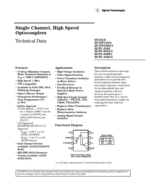
Single Channel, High Speed Optocouplers Technical DataFeatures• 15 kV/µs Minimum Common Mode Transient Immunity at V CM = 1500 V (4503/0453)• High Speed: 1 Mb/s • TTL Compatible• Available in 8-Pin DIP, SO-8,Widebody Packages • Open Collector Output • Guaranteed Performance from Temperature: 0°C to 70°C• Safety ApprovalUL Recognized – 3750 V rms for 1 minute (5000 V rms for 1 minute for HCNW and Option 020 devices) per UL1577CSA ApprovedIEC/EN/DIN EN 60747-5-2Approved–V IORM = 630 V peak for HCPL-4503#060–V IORM = 1414 V peak for HCNW devices• Dual Channel VersionAvailable (253X/4534/053X/0534)• MIL-PRF-38534 Hermetic Version Available (55XX/65XX/4N55)Applications• High Voltage Insulation • Video Signal Isolation• Power Transistor Isolation in Motor Drives • Line Receivers• Feedback Element in Switched Mode Power Supplies• High Speed Logic Ground Isolation – TTL/TTL, TTL/CMOS, TTL/LSTTL• Replaces Pulse Transformers • Replaces SlowPhototransistor Isolators • Analog Signal Ground IsolationDescriptionThese diode-transistor optocoup-lers use an insulating layerbetween a LED and an integrated photodetector to provide elec-trical insulation between input and output. Separate connections for the photodiode bias and output-transistor collector increase the speed up to ahundred times that of a conven-tional phototransistor coupler by reducing the base-collector capacitance.Functional Diagram6N135/6HCNW135/6HCNW4502/3HCPL-2502HCPL-0452/3HCPL-0500/1HCPL-4502/3CAUTION: It is advised that normal static precautions be taken in handling and assembly of this component to prevent damage and/or degradation which may be induced by ESD.A 0.1 µF bypass capacitor must be connected between pins 5 and 8.V CC V B V O GND** NOTE: FOR 4502/3, 0452/3,PIN 7 IS NOT CONNECTED.TRUTH TABLE (POSITIVE LOGIC)LEDONOFFV O LOW HIGHGNDV CCOANODECATHODEB* NOTE: FOR HCPL-4502/-3, HCPL-0452/3, HCNW4502/3, PIN 7 IS NOT CONNECTED.Ordering InformationSpecify Part Number followed by Option Number (if desired).Example:HCPL-4503#XXXX020 =UL 5000 V rms/1 Minute Option*060 =IEC/EN/DIN EN 60747-5-2 V IORM = 630 V peak Option**300 =Gull Wing Surface Mount Option†500 =Tape and Reel Packaging Option XXXE = Lead Free OptionOption data sheets available. Contact your Agilent sales representative or authorized distributor for information.*For 6N135/6 and HCPL-4502/3 only.**For HCPL-4503 only. Combination of Option 020 and Option 060 is not available.†Gull wing surface mount option applies to through hole parts only.*Technical data for these products are on separate Agilent publications.†Pin 7, transistor base, is not connected.output current for 1 TTL load and a 5.6 k Ω pull-up resistor. CTR for these devices is 19% minimum at I F =16mA.The HCPL-4502, HCPL-0452,and HCNW4502 provide the electrical and switching performance of the 6N136,HCPL-0501, and HCNW136 with increased ESD protection.The HCPL-4503, HCPL-0453,and HCNW4503 are similar to the HCPL-4502, HCPL-0452, and HCNW4502 optocouplers but have increased common mode transient immunity of 15 kV/µs minimum at V CM =1500V guaranteed.These single channel optocoup-lers are available in 8-Pin DIP,SO-8 and Widebody package configurations.The 6N135, HCPL-0500, and HCNW135 are for use in TTL/CMOS, TTL/LSTTL or wide bandwidth analog applications.Current transfer ratio (CTR) for these devices is 7% minimum at I F =16mA.The 6N136, HCPL-2502,HCPL-0501, and HCNW136 are designed for high speed TTL/TTL applications. A standard 16 mA TTL sink current through the input LED will provide enoughRemarks: The notation “#” is used for existing products, while (new) products launched since 15th July 2001 and lead free option will use “-”Package Outline Drawings8-Pin DIP Package (6N135/6, HCPL-4502/3, HCPL-2502)8-Pin DIP Package with Gull Wing Surface Mount Option 300 (6N135/6, HCPL-4502/3)0.254+ 0.076- 0.051(0.010+ 0.003)- 0.002)DIMENSIONS IN MILLIMETERS AND (INCHES).*MARKING CODE LETTER FOR OPTION NUMBERS "L" = OPTION 020"V" = OPTION 060OPTION NUMBERS 300 AND 500 NOT MARKED.NOTE: FLOATING LEAD PROTRUSION IS 0.25 mm (10 mils) MAX.(0.025 ± 0.005)(0.100)BSCDIMENSIONS IN MILLIMETERS (INCHES).LEAD COPLANARITY = 0.10 mm (0.004 INCHES).NOTE: FLOATING LEAD PROTRUSION IS 0.25 mm (10 mils) MAX.+ 0.076- 0.051+ 0.003)- 0.002)Small Outline SO-8 Package (HCPL-0500/1, HCPL-0452/3)8-Pin Widebody DIP Package (HCNW135/6, HCNW4502/3)(0.012)MIN.5.207 ± 0.254 (0.205 ± 0.010)DIMENSIONS IN MILLIMETERS (INCHES).LEAD COPLANARITY = 0.10 mm (0.004 INCHES) MAX.*1.78 ± 0.15NOTE: FLOATING LEAD PROTRUSION IS 0.25 mm (10 mils) MAX.0.254+ 0.076- 0.0051+ 0.003)- 0.002)8-Pin Widebody DIP Package with Gull Wing Surface Mount Option 300 (HCNW135/6,HCNW4502/3)Solder Reflow Temperature ProfileTIME (SECONDS)T E M P E R A T U R E (°C )ROOM1.78 ± 0.15MAX.BSCDIMENSIONS IN MILLIMETERS (INCHES).LEAD COPLANARITY = 0.10 mm (0.004 INCHES).NOTE: FLOATING LEAD PROTRUSION IS 0.25 mm (10 mils) MAX.Regulatory InformationThe devices contained in this data sheet have been approved by the following organizations:ULRecognized under UL 1577,Component Recognition Program, File E55361.CSAApproved under CSA Component Acceptance Notice #5, File CA 88324.Insulation and Safety Related Specifications8-Pin DIP Widebody (300 Mil)SO-8(400 Mil)Parameter Symbol Value Value Value Units ConditionsMinimum External L(101)7.14.99.6mmMeasured from input terminals Air Gap (External to output terminals, shortest Clearance)distance through air.Minimum External L(102)7.4 4.810.0mmMeasured from input terminals Tracking (External to output terminals, shortest Creepage)distance path along body.Minimum Internal 0.080.08 1.0mmThrough insulation distance,Plastic Gapconductor to conductor, usually (Internal Clearance)the direct distance between the photoemitter and photodetector inside the optocoupler cavity.Minimum Internal NA NA 4.0mmMeasured from input terminals Tracking (Internal to output terminals, along Creepage)internal cavity.Tracking Resistance CTI 200200200VoltsDIN IEC 112/VDE 0303 Part 1(Comparative Tracking Index)Isolation GroupIIIa IIIa IIIaMaterial Group(DIN VDE 0110, 1/89, Table 1)Option 300 - surface mount classification is Class A in accordance with CECC 00802.IEC/EN/DIN EN 60747-5-2Approved underIEC 60747-5-2:1997 + A1:2002EN 60747-5-2:2001 + A1:2002DIN EN 60747-5-2 (VDE 0884 Teil 2):2003-01(HCNW and Option 060 only)Recommended Pb-Free IR Profile°C of ACTUAL NOTES:THE TIME FROM 25 °C to PEAK TEMPERATURE = 8 MINUTES MAX.T smax = 200 °C, T smin = 150 °CIEC/EN/DIN EN 60747-5-2 Insulation Related Characteristics(HCPL-4503 OPTION 060 ONLY)IEC/EN/DIN EN 60747-5-2 Insulation Related Characteristics (HCNW135/6, HCNW4502/3 ONLY)*Refer to the front of the optocoupler section of the current catalog, under Product Safety Regulations section IEC/EN/DIN EN60747-5-2, for a detailed description.Note: Isolation characteristics are guaranteed only within the safety maximum ratings which must be ensured by protective circuits in application.*Data has been registered with JEDEC for the 6N135/6N136.Electrical Specifications (DC)Over recommended temperature (T A = 0°C to 70°C) unless otherwise specified. See note 13.Parameter Symbol Device Min.Typ.**Max.Units Test Conditions Fig.Note Current CTR*6N13571850%T A = 25°C V O = 0.4 V I F = 16 mA,1, 2,5, 11 Transfer Ratio HCPL-0500V CC = 4.5 V4HCNW135519V O = 0.5 VHCPL-25021522T A = 25°C V O = 0.4 V1525V O = 0.5 V6N136192450T A = 25°C V O = 0.4 VHCPL-4502/3HCPL-05011525V O = 0.5 VHCPL-0452/3HCNW136HCNW4502/3Logic Low V OL6N1350.10.4V T A = 25°C I O = 1.1 mA I F = 16 mA,Output Voltage HCPL-0500V CC = 4.5 VHCNW1350.10.5I O = 0.8 mA6N1360.10.4T A = 25°C I O = 3.0 mAHCPL-2502HCPL-4502/30.10.5I O = 2.4 mAHCPL-0501HCPL-0452/3HCNW136HCNW4502/3Logic High I OH*0.0030.5µA T A = 25°C V O = V CC = 5.5 V I F = 0 mA7Output Current0.011T A = 25°C V O = V CC = 15 V50V O = V CC = 15 VLogic Low I CCL50200µA I F = 16 mA, V O = Open, V CC = 15 V13 Supply CurrentLogic High I CCH*0.021µA T A = 25°C I F = 16 mA, V O = Open,13 Supply Current2V CC = 15 VInput Forward V F*8-Pin DIP 1.5 1.7V T A = 25°C I F = 16 mA3Voltage SO-8 1.8Widebody 1.45 1.68 1.85T A = 25°C I F = 16 mA1.35 1.95Input Reverse BV R*8-Pin DIP5V I R = 10 µABreakdown SO-8Voltage Widebody3I R = 100 µATemperature∆V F/8-Pin DIP-1.6mV/°C I F = 16 mACoefficient of∆T A SO-8Forward Voltage Widebody-1.9Input C IN8-Pin DIP60pF f = 1 MHz, V F = 0 VCapacitance SO-8Widebody90Transistor DC h FE8-Pin DIP150V O = 5 V, I O = 3 mACurrent Gain SO-8130V O = 0.4 V, I B = 20 µAWidebody180V O = 5 V, I O = 3 mA160V O = 0.4 V, I B = 20 µA*For JEDEC registered parts.**All typicals at T A = 25°C.Parameter Sym.Device Min.Typ.**Max.Units Test ConditionsFig.Note Propagation t PHL *6N1350.2 1.5µs T A = 25°C R L = 4.1 k Ω5, 6,8, 9HCPL-0500 2.011HCNW1356N1360.20.8T A = 25°C R L = 1.9 k ΩHCPL-2502HCPL-4502/3HCPL-0501HCPL-0452/3 1.0HCNW136HCNW4502/3Propagation t PLH *6N135 1.3 1.5µsT A = 25°C R L = 4.1 k Ω5, 6,8, 9HCPL-0500 2.011HCNW1356N1360.60.8T A = 25°C R L = 1.9 k ΩHCPL-2502HCPL-4502/3HCPL-0501HCPL-0452/3 1.0HCNW136HCNW4502/3Common Mode |CM H |6N1351kV/µs R L = 4.1 k ΩI F = 0 mA, T A = 25°C,127, 8,HCPL-0500V CM = 10 V p-p 9HCNW135C L = 15 pF6N1361R L = 1.9 k ΩHCPL-2502HCPL-4502HCPL-0501HCPL-0452HCNW4502HCPL-45031530R L = 1.9 k ΩI F = 0 mA, T A = 25°C,HCPL-0453V CM = 1500 V p-p ,HCNW4503C L = 15 pFCommon Mode |CM L |6N1351kV/µs R L = 4.1 k ΩI F = 16 mA, T A = 25°C,127, 8,HCPL-0500V CM = 10 V p-p 9HCNW135C L = 15 pF6N1361R L = 1.9 k ΩHCPL-2502HCPL-4502HCPL-0501HCPL-0452HCNW4502HCPL-45031530R L = 1.9 k ΩI F = 16 mA, T A = 25°C,HCPL-0453V CM = 1500 V p-p ,HCNW4503C L = 15 pFBandwidth BW 6N135/69MHzSee Test Circuit8, 1010HCPL-2502HCPL-0500/1HCNW135/611*For JEDEC registered parts.**All typicals at T A = 25°C.Switching Specifications (AC)Over recommended temperature (T A = 0°C to 70°C), V CC = 5 V, I F = 16 mA unless otherwise specified.Delay Time to Logic Low at OutputDelay Time to Logic High at OutputTransient Immunity at Logic High Level OutputTransient Immunity at Logic Low Level OutputPackage CharacteristicsOver recommended temperature (T A = 0°C to 70°C) unless otherwise specified.*All typicals at T A = 25°C.**The Input-Output Momentary Withstand Voltage is a dielectric voltage rating that should not be interpreted as an input-output continuous voltage rating. For the continuous voltage rating refer to the IEC/EN/DIN EN 60747-5-2 Insulation Related Characteristics Table (if applicable), your equipment level safety specification or Agilent Application Note 1074 entitled “Optocoupler Input-Output Endurance Voltage,” publication number 5963-2203E.Notes:1.Derate linearly above 70°C free-air temperature at a rate of 0.8 mA/°C (8-Pin DIP).Derate linearly above 85°C free-air temperature at a rate of 0.5 mA/°C (SO-8).2.Derate linearly above 70°C free-air temperature at a rate of 1.6 mA/°C (8-Pin DIP).Derate linearly above 85°C free-air temperature at a rate of 1.0 mA/°C (SO-8).3.Derate linearly above 70°C free-air temperature at a rate of 0.9 mW/°C (8-Pin DIP).Derate linearly above 85°C free-air temperature at a rate of 1.1 mW/°C (SO-8).4.Derate linearly above 70°C free-air temperature at a rate of 2.0 mW/°C (8-Pin DIP).Derate linearly above 85°C free-air temperature at a rate of 2.3 mW/°C (SO-8).5.CURRENT TRANSFER RATIO in percent is defined as the ratio of output collector current, I O, to the forward LED input current, I F,times 100.6.Device considered a two-terminal device: Pins 1, 2, 3, and 4 shorted together and Pins 5, 6, 7, and 8 shorted together.mon mode transient immunity in a Logic High level is the maximum tolerable (positive) dV CM/dt on the leading edge of thecommon mode pulse signal, V CM, to assure that the output will remain in a Logic High state (i.e., V O > 2.0 V). Common mode transient immunity in a Logic Low level is the maximum tolerable (negative) dV CM/dt on the trailing edge of the common mode pulse signal, V CM, to assure that the output will remain in a Logic Low state (i.e., V O < 0.8 V).8.The 1.9 kΩ load represents 1 TTL unit load of 1.6 mA and the 5.6 kΩ pull-up resistor.9.The 4.1 kΩ load represents 1 LSTTL unit load of 0.36 mA and 6.1 kΩ pull-up resistor.10.The frequency at which the ac output voltage is 3 dB below its mid-frequency value.11.The JEDEC registration for the 6N136 specifies a minimum CTR of 15%. Agilent guarantees a minimum CTR of 19%.12.See Option 020 data sheet for more information.e of a 0.1 µf bypass capacitor connected between pins 5 and 8 is recommended.14.In accordance with UL 1577, each optocoupler is proof tested by applying an insulation test voltage ≥ 4500 V rms for 1 second(leakage detection current limit, I I-O≤ 5 µA). This test is performed before the 100% Production test shown in the IEC/EN/DIN EN 60747-5-2 Insulation Related Characteristics Table if applicable.15.In accordance with UL 1577, each optocoupler is proof tested by applying an insulation test voltage ≥ 6000 V rms for 1 second(leakage detection current limit, I I-O≤ 5 µA). This test is performed before the 100% Production test shown in the IEC/EN/DIN EN 60747-5-2 Insulation Related Characteristics Table if applicable.16.This rating is equally validated by an equivalent ac proof test.Figure 2. Current Transfer Ratio vs. Input Current.Figure 3. Input Current vs. Forward Voltage.Figure 1. DC and Pulsed Transfer Characteristics.105V O – OUTPUT VOLTAGE – VI O – O U T P U T C U R R E N T – m A8 PIN DIP, SO-8128V O – OUTPUT VOLTAGE – VI O – O U T P U T C U R R E N T – m A416WIDEBODY1.51.00.5N O R M A L I Z E D C U R R E N T T R A N S F E R R A T I OI F – INPUT CURRENT – mA8 PIN DIP, SO-80N O R M A L I Z E D C U R R E N T T R A N S F E R R A T I OI F – INPUT CURRENT – mA1.50.51.0WIDEBODYV F – FORWARD VOLTAGE –VOLTS I F – F O R W A R D C U R R E N T – m A8 PIN DIP, SO-8V F –FORWARD VOLTAGE – VOLTS1000100101.00.10.001I F – F O R W A R D C U R R E N T – m AWIDEBODYFigure 6. Propagation Delay Time vs. Load Resistance.Figure 5. Propagation Delay vs. Temperature.Figure 4. Current Transfer Ratio vs. Temperature.1.00.90.80.70.6N O R M A L I Z E D C U R R E N T T R A N S F E R R A T I OT A – TEMPERATURE – °C 8 PIN DIP, SO-81.11.00.90.80.70.660N O R M A L I Z E D C U R R E N T T R A N S F E R R A T I OT A – TEMPERATURE – °C0.50.4WIDEBODY1.0R L – LOAD RESISTANCE – (k Ω)t P – P R O P A G A T I O N D E L A Y – µs8 PIN DIP, SO-8R L – LOAD RESISTANCE – (k Ω)t P – P R O P A G A T I O N D E L A Y – µs6.04.01.00.60.40.2WIDEBODY150010005000t p – P R O P A G A T I O N D E L A Y – n sT A – TEMPERATURE – °C 8 PIN DIP, SO-81000800600400200T A – TEMPERATURE – °CWIDEBODYt p – P R O P A G A T I O N D E L A Y – n sFigure 9. Thermal Derating Curve, Dependence of Safety Limiting Value with Case Temperature per IEC/EN/DIN EN 60747-5-2.Figure 8. Small-Signal Current Transfer Ratio vs. Quiescent Input Current.Figure 7. Logic High Output Current vs. Temperature.T A – TEMPERATURE – °C10+410101001010+210+3I O H – L O G I C H I G H O U T P U T C U R R E N T – n A8 PIN DIP, SO-8I O H– L O G I C H I G H O U T P U T C U R R E N T – n AT A – TEMPERATURE – °C10101010WIDEBODY∆ I F∆I O – S M A L L S I G N A L C U R R E N T T R A N S F E R R A T I O I F – QUIESCENT INPUT CURRENT – mA 8 PIN DIP, SO-80.30∆ I F ∆ I O– S M A L L S I G N A L C U R R E N T T R A N S F E R R A T I OI F – QUIESCENT INPUT CURRENT – mAWIDEBODYO U T P U TP O W E R – P S , I N P U T C U R R E N T – I ST S – CASE TEMPERATURE – °C O U T P U T P OW E R – P S , I N P U T C U R R E N T – I S0T S – CASE TEMPERATURE – °C1000400600800200100300500700900Figure 10. Frequency Response.HCNW135/6HCNW135/60.11.010100-20-15-10-5+5T A = 25 °Cf - FREQUENCY - MHzN O R M A L I Z E D R E S P O N S E - d B6N135/6, HCPL-0500/1, HCPL-2502V TYPICAL I = 9 mA FO6N135/6, HCPL-0500/1, HCPL-2502Figure 12. Test Circuit for Transient Immunity and Typical Waveforms.Figure 11. Switching Test Circuit.OF= 1.5 µFt V I F OVOV O/semiconductorsFor product information and a complete list ofdistributors, please go to our web site.For technical assistance call:Americas/Canada: +1 (800) 235-0312 or (916) 788-6763Europe: +49 (0) 6441 92460China: 10800 650 0017Hong Kong: (+65) 6756 2394India, Australia, New Zealand: (+65) 6755 1939Japan: (+81 3) 3335-8152 (Domestic/Interna-tional), or 0120-61-1280 (Domestic Only)Korea: (+65) 6755 1989Singapore, Malaysia, Vietnam, Thailand,Philippines, Indonesia: (+65) 6755 2044Taiwan: (+65) 6755 1843Data subject to change.Copyright © 2004 Agilent Technologies, Inc.Obsoletes 5989-0305EN December 20, 20045989-2112EN。
1N4749中文资料

Fig 1. Thermal resistance from junction to tie-point as a function of pulse duration; lead length 4 mm
7. Characteristics
Table 7. Characteristics Tj = 25 °C unless otherwise specified.
[1] The series consists of 22 types with nominal working voltages from 3.3 V to 24 V.
Version SOD66
Table 4. Marking codes Type number 1N4728A to 1N4749A
The series consists of 22 types with nominal working voltages from 3.3 to 24 V.
1.2 Features
I Total power dissipation: max. ≤ 1000 mW
I Working voltage range: nom. 3.3 V to 24 V
3 of 10
NXP Semiconductors
1N4728A to 1N4749A
Voltage regulator diodes
Table 8. Characteristics per type Tj = 25 °C unless otherwise specified.
Type number
146
1
10
4
133
0.5
10
5
121
0.5
AO4459中文资料

AO4459中⽂资料SymbolTyp Max 33406275R θJL 1824Maximum Junction-to-Lead CSteady-State°C/WThermal Characteristics ParameterUnits Maximum Junction-to-AmbientAt ≤ 10s R θJA °C/W Maximum Junction-to-Ambient ASteady-State °C/W AO4459AO4459SymbolMin TypMaxUnits BV DSS -30V -1T J =55°C-5I GSS ±100nA V GS(th)-1.5-1.85-2.5V I D(ON)-30A 3846T J =125°C53685872m ?g FS 11S V SD -0.78-1V I S-3.5A C iss 668830pF C oss 126pF C rss 92pF R g69?Q g (10V)12.716nC Q g (4.5V) 6.4nC Q gs 2nC Q gd 4nC t D(on)7.7ns t r 6.8ns t D(off)20ns t f 10ns t rr 2230ns Q rr15nCTHIS PRODUCT HAS BEEN DESIGNED AND QUALIFIED FOR THE CONSUMER MARKET. APPLICATIONS OR USES AS CRITICAL COMPONENTS IN LIFE SUPPORT DEVICES OR SYSTEMS ARE NOT AUTHORIZED. AOS DOES NOT ASSUME ANY LIABILITY ARISING OUT OF SUCH APPLICATIONS OR USES OF ITS PRODUCTS. AOS RESERVES THE RIGHT TO IMPROVE PRODUCT DESIGN,FUNCTIONS AND RELIABILITY WITHOUT NOTICE.DYNAMIC PARAMETERS Maximum Body-Diode Continuous CurrentGate resistanceV GS =0V, V DS =0V, f=1MHzV GS =0V, V DS =-15V, f=1MHz Input Capacitance Output Capacitance Turn-On Rise Time Turn-Off DelayTime V GS =-10V, V DS =-15V, R L =2.5?, R GEN =3?Turn-Off Fall TimeTurn-On DelayTime SWITCHING PARAMETERSTotal Gate Charge (4.5V)Gate Source Charge Gate Drain Charge Total Gate Charge (10V)V GS =-10V, V DS =-15V, I D =-6.5Am ?V GS =-4.5V, I D =-5AI S =-1A,V GS =0V V DS =-5V, I D =-6.5AR DS(ON)Static Drain-Source On-ResistanceForward TransconductanceDiode Forward VoltageI DSS µA Gate Threshold Voltage V DS =V GS I D =-250µA V DS =-24V, V GS =0VV DS =0V, V GS =±20V Zero Gate Voltage Drain Current Gate-Body leakage current Electrical Characteristics (T J =25°C unless otherwise noted)STATIC PARAMETERS ParameterConditions Body Diode Reverse Recovery Time Body Diode Reverse Recovery ChargeI F =-6.5A, dI/dt=100A/µsDrain-Source Breakdown Voltage On state drain currentI D =-250µA, V GS =0V V GS =-10V, V DS =-5V V GS =-10V, I D =-6.5AReverse Transfer Capacitance I F =-6.5A, dI/dt=100A/µs A: The value of R θJA is measured with the device mounted on 1in 2FR-4 board with 2oz. Copper, in a still air environment with T A =25°C. The value in any a given application depends on the user's specific board design. The current rating is based on the t ≤ 10s thermal resistance rating.B: Repetitive rating, pulse width limited by junction temperature.C. The R θJA is the sum of the thermal impedence from junction to lead R θJL and lead to ambient.D. The static characteristics in Figures 1 to 6 are obtained using < 300µs pulses, duty cycle 0.5% max.E. These tests are performed with the device mounted on 1 in 2FR-4 board with 2oz. Copper, in a still air environment with T A =25°C. The SOA curve provides a single pulse rating. Rev0 Sept 2006AO4459AO4459。
isis元件-符号-对照表
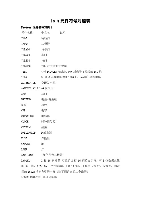
isis元件符号对照表Proteus 元件名称对照1元件名称中文名说明7407 驱动门1N914 二极管74Ls00 与非门74LS04 非门74LS08 与门74LS390 TTL 双十进制计数器7SEG 4针BCD-LED 输出从0-9 对应于4根线的BCD码7SEG 3—8译码器电路BCD-7SEG[size=+0]转换电路ALTERNATOR 交流发电机AMMETER-MILLI mA安培计AND 与门BATTERY 电池/电池组BUS 总线CAP 电容CAPACITOR 电容器CLOCK 时钟信号源CRYSTAL 晶振D-FLIPFLOP D触发器FUSE 保险丝GROUND 地LAMP 灯LED—RED 红色发光二极管LM016L 2行16列液晶可显示2行16列英文字符,有8位数据总线D0-D7,RS,R/W,EN三个控制端口(共14线),工作电压为5V。
没背光,和常用的1602B功能和引脚一样(除了调背光的二个线脚)LOGIC ANALYSER 逻辑分析器LOGICPROBE 逻辑探针LOGICPROBE[BIG] 逻辑探针用来显示连接位置的逻辑状态LOGICSTATE 逻辑状态用鼠标点击,可改变该方框连接位置的逻辑状态LOGICTOGGLE 逻辑触发MASTERSWITCH 按钮手动闭合,立即自动打开MOTOR 马达OR 或门POT-LIN 三引线可变电阻器POWER 电源RES 电阻RESISTOR 电阻器SWITCH 按钮手动按一下一个状态SWITCH-SPDT 二选通一按钮VOLTMETER 伏特计VOLTMETER-MILLI mV伏特计VTERM 串行口终端Electromechanical 电机Inductors 变压器Laplace Primitives 拉普拉斯变换Memory IcsMicroprocessor IcsMiscellaneous 各种器件 AERIAL—天线;ATAHDD;ATMEGA64;BATTERY;CELL;CRYSTAL—晶振;FUSE;METER-仪表;Modelling Primitives 各种仿真器件是典型的基本元器模拟,不表示具体型号,只用于仿真,没有PCBOptoelectronics 各种发光器件发光二极管,LED,液晶等等PLDs & FPGAsResistors 各种电阻Simulator Primitives 常用的器件Speakers & SoundersSwitches & Relays button 开关,继电器,键盘Switching Devices 晶阊管Transistors 晶体管(三极管,场效应管) TTL 74 seriesTTL 74ALS seriesTTL 74AS seriesTTL 74F seriesTTL 74HC seriesTTL 74HCT seriesTTL 74LS seriesTTL 74S seriesAnalog Ics 模拟电路集成芯片Capacitors 电容集合CMOS 4000 seriesConnectors 排座,排插Data Converters ADC,DACDebugging Tools 调试工具ECL 10000 SeriesPROTEUS 元件库元件名称及中英对照AND 与门ANTENNA 天线BATTERY 直流电源BELL 铃,钟BVC 同轴电缆接插件BRIDEG 1 整流桥(二极管)BRIDEG 2 整流桥(集成块)BUFFER 缓冲器BUZZER 蜂鸣器CAP 电容CAPACITOR 电容CAPACITOR POL 有极性电容CAPVAR 可调电容CIRCUIT BREAKER 熔断丝COAX 同轴电缆CON 插口CRYSTAL 晶体整荡器DB 并行插口DIODE 二极管DIODE SCHOTTKY 稳压二极管DIODE VARACTOR 变容二极管DPY_3—SEG 3段LEDDPY_7-SEG 7段LEDDPY_7—SEG_DP 7段LED(带小数点)ELECTRO 电解电容FUSE 熔断器INDUCTOR 电感INDUCTOR IRON 带铁芯电感INDUCTOR3 可调电感JFET N N沟道场效应管JFET P P沟道场效应管LAMP 灯泡LAMP NEDN 起辉器LED 发光二极管METER 仪表MICROPHONE 麦克风MOSFET MOS管MOTOR AC 交流电机MOTOR SERVO 伺服电机NAND 与非门NOR 或非门NOT 非门NPN NPN三极管NPN-PHOTO 感光三极管OPAMP 运放OR 或门PHOTO 感光二极管PNP 三极管NPN DAR NPN三极管PNP DAR PNP三极管POT 滑线变阻器PELAY-DPDT 双刀双掷继电器RES1.2 电阻RES3。
EP3C120F484I7N中文资料(Altera)中文数据手册「EasyDatasheet - 矽搜」
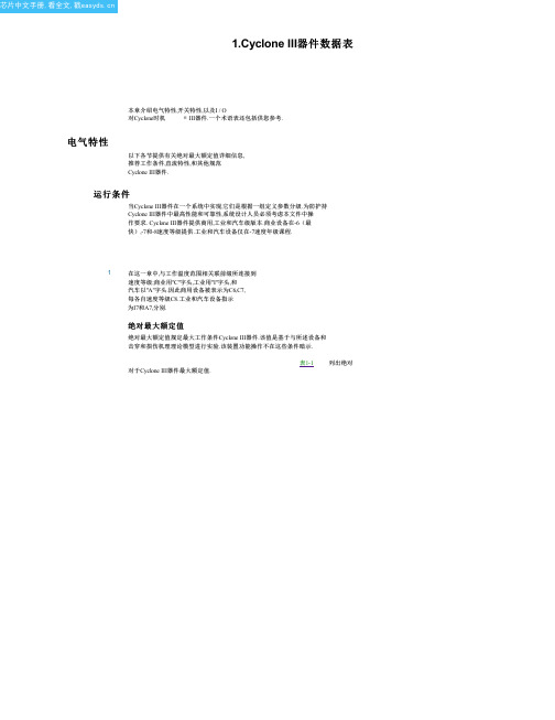
Typ Max Unit — 10 mA — 10 mA
总线防护持
总线防护持防护留源在最后一个有效逻辑状态,驾驶它要么进入高阻抗状态或者被删除 .每个I / O引脚有一个选项,以使总线防护持在用户模式.总线防护持始终在 配置模式禁用.
表1-5 列出总线防护持规格Cyclone III器件.
表 1-5. Cyclone III器件总线防护持参数
电源电压为输出缓冲器,3.3-V
手术
—
1.15 1.2 1.25
V
—
3.135 3.3 3.465 V
电源电压为输出缓冲器,3.0-V
手术
—
2.85
3
3.15
V
VCCIO (3), (4)
电源电压为输出缓冲器,2.5-V
手术
电源电压为输出缓冲器,1.8-V
手术
电源电压为输出缓冲器,1.5-V
手术
—
2.375 2.5 2.625 V
对于Cyclone III器件最大额定值.
表1-1 列出绝对
芯片中文手册,看全文,戳
1–2
第 1章: Cyclone III器件数据表
电气特性
1
超出所列条件
表1-1 对器件造成永久性损坏.
此外,在延长时间周期绝对最大额定值设备操作具有设备不利影响.
表 1-1. Cyclone III器件绝对最大额定值
–40 — 125 °C
50 µs — 50毫秒 —
50 µs — 3毫秒 —
—
—
10
mA
须知 表 1-3:
(1) V 所有I / O块设备操作过程中都必须启动.所有V 必须启动和关断同时.
管脚必须供电到2.5 V(即使不使用PLL)和
74LS139中文资料
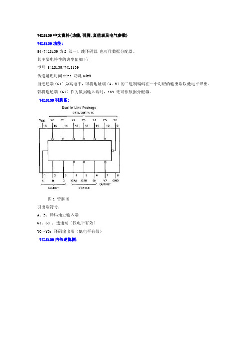
-20 -
6.8
20 -0.36 -100 11
μA mA mA mA
动态特性: RL = 2 kW 符号 参数 Fro (Input) To (Output) CL = 15 pF Min tPLH tPHL tPLH tPHL 低到高输出传递延迟时间 高到低输出传递延迟时间 低到高输出传递延迟时间 高到低输出传递延迟时间 Select to Output Select to Output Enable to Output Enable to Output Max 18 27 18 24 CL = 50 pF Min Max 27 40 27 40 ns ns ns ns 单位
电气参数: 符号 VI VOH 参数 输入钳位电压 输出高电平电压 测试条件 VCC = Min, II = -18 mA VCC = Min, IOH = Max, VIL = Max, VIH = Min VCC = Min, IOL = Max, VIL VOL 输出低电平电压 = Max, VIH = Min IOL = 4 mA, VCC = Min II 最大输入电压时输入电流 VCC = Max, VI = 7V 最大值 2.7 典型值 3.4 最大值 -1.5 单 位 V V
图 1 管脚图 引出端符: A、B:译码地址输入端 G1、G2 :选通端(低电平有效) Y0~Y3:译码输出端(低电平有效) 74LS139 内部逻辑图:
图 2 内部逻辑引脚功能 74LS139 电气参数: 建议操作条件: 符号 VCC VIH VIL IOH IOL TA 参数 电源电压 输入高电平电压 ViH 输入低电平电压 VIL 输出高电平电流 IOH 输出低电平电流 IOL 工作温度 最小值 4.75 2 0 典型值 5 最大值 5.25 0.8 -0.4 8 70 单位 V V V mA mA ℃
1830499中文资料
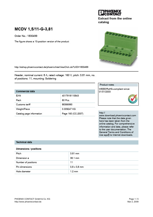
Extract from the onlinecatalogMCDV 1,5/11-G-3,81Order No.: 1830499The figure shows a 10-position version of the producthttp://eshop.phoenixcontact.de/phoenix/treeViewClick.do?UID=1830499Header, nominal current: 8 A, rated voltage: 160 V, pitch: 3.81 mm, no. of positions: 11, mounting: Solderinghttp://Please note that the data givenhere has been taken from theonline catalog. For comprehensiveinformation and data, please referto the user documentation. TheGeneral Terms and Conditions ofUse apply to Internet downloads. Technical dataDimensions / positionsPitch 3.81 mmDimension a38.1 mmNumber of positions11Pin dimensions0,8 x 0,8 mmHole diameter 1.2 mmTechnical dataInsulating material group IIIaRated surge voltage (III/3) 2.5 kVRated surge voltage (III/2) 2.5 kVRated surge voltage (II/2) 2.5 kVRated voltage (III/2)160 VRated voltage (II/2)250 VConnection in acc. with standard EN-VDENominal current I N8 ANominal voltage U N160 VMaximum load current8 AInsulating material PBTInflammability class acc. to UL 94V0Certificates / ApprovalsApproval logoCSANominal voltage U N300 VNominal current I N8 ACULNominal voltage U N300 VNominal current I N8 AULNominal voltage U N300 VNominal current I N8 ACertification CB, CSA, CUL, GOST, UL, VDE-PZIAccessoriesItem Designation DescriptionMarking0804109SK 3,81/2,8:FORTL.ZAHLEN Marker card, printed horizontally, self-adhesive, 10-section markerstrip, 14 identical decades marked 1-10, 11-20 etc. up to 91-(99)100, sufficient for 140 terminal blocksPlug/Adapter1734634CP-MSTB Coding profile, is inserted into the slot on the plug or invertedheader, red insulating materialAdditional productsItem Designation DescriptionGeneral1851135FK-MCP 1,5/11-ST-3,81Plug component, nominal current: 8 A, rated voltage: 160 V, pitch:3.81 mm, no. of positions: 11, type of connection: Spring-cageconnection1850754FRONT-MC 1,5/11-ST-3,81Plug component, nominal current: 8 A, rated voltage: 160 V,pitch: 3.81 mm, no. of positions: 11, type of connection: Screwconnection1862661IMC 1,5/11-G-3,81Header, nominal current: 8 A, rated voltage: 160 V, pitch: 3.81mm, no. of positions: 11, mounting: Soldering1875519IMCV 1,5/11-G-3,81Header, nominal current: 8 A, rated voltage: 160 V, pitch: 3.81mm, no. of positions: 11, mounting: Soldering1803662MC 1,5/11-ST-3,81Plug component, nominal current: 8 A, rated voltage: 160 V,pitch: 3.81 mm, no. of positions: 11, type of connection: Screwconnection1852260MCC 1/11-STZ-3,81Plug component, nominal current: 8 A, rated voltage: 160 V,pitch: 3.81 mm, no. of positions: 11, type of connection: Crimpconnection1827211MCVR 1,5/11-ST-3,81Plug component, nominal current: 8 A, rated voltage: 160 V,pitch: 3.81 mm, no. of positions: 11, type of connection: Screwconnection1827062MCVW 1,5/11-ST-3,81Plug component, nominal current: 8 A, rated voltage: 160 V,pitch: 3.81 mm, no. of positions: 11, type of connection: Screwconnection1897487QC 0,5/11-ST-3,81Plug, nominal current: 6 A, rated voltage: 320 V, pitch: 3.81mm, number of positions: 11, connection method: Insulationdisplacement connection QUICKONDrawingsDrilling diagramDimensioned drawingAddressPHOENIX CONTACT GmbH & Co. KGFlachsmarktstr. 832825 Blomberg,GermanyPhone +49 5235 3 00Fax +49 5235 3 41200http://www.phoenixcontact.de© 2008 Phoenix ContactTechnical modifications reserved;。
IN4744A中文资料
Value
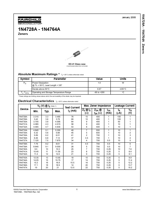
1.0
6.67 -65 to +200
Electrical Characteristics Ta = 25°C unless otherwise noted
Device
1N4728A 1N4729A 1N4730A 1N4731A 1N4732A
1N4733A 1N4734A 1N4735A 1N4736A 1N4737A
For BZxx series: 4th to 6th characters of the device name. 4.0 Third Line: Device name - For 1Nxx series: 5th to 6th characters of the device name.
For BZXyy series: Voltage rating 5.0 Third Line: Device name - For 1Nxx series: 7th to 8th characters of the device name.
2 1N4728A - 1N4764A Rev. G2
1N4728A - 1N4764A Zeners
元器件交易网
Top Mark Information
Device
1N4728A 1N4729A 1N4730A 1N4731A 1N4732A
1
1N4728A - 1N4764A Rev. G2
1N4728A - 1N4764A Zeners
元器件交易网
Electrical Characteristics TC = 25°C unless otherwise noted
ZZK @ IZK (Ω)
IXFN130N30中文资料

© 2003 IXYS All rights reservedFeatures•International standard packages •miniBLOC, with Aluminium nitrideisolation•Low R DS (on) HDMOS TM process•Rugged polysilicon gate cell structure •Unclamped Inductive Switching (UIS)rated•Low package inductance •Fast intrinsic RectifierApplications•DC-DC converters •Battery chargers•Switched-mode and resonant-modepower supplies •DC choppers•Temperature and lighting controlsAdvantages•Easy to mount •Space savings •High power densitySymbolTest ConditionsCharacteristic Values(T J = 25°C, unless otherwise specified)min.typ.max.V DSS V GS = 0 V, I D = 3 mA 300V V GH(th)V DS = V GS , I D = 8 mA 24V I GSS V GS = ±20 V DC , V DS = 0±200nA I DSS V DS = V DSS T J = 25°C 100µA V GS = 0 VT J = 125°C2mAR DS(on)V GS = 10 V, I D = 0.5 • I D2522m ΩPulse test, t ≤ 300 µs,duty cycle d ≤ 2 %Symbol Test Conditions Maximum RatingsV DSS T J = 25°C to 150°C300V V DGR T J = 25°C to 150°C; R GS = 1 M Ω300V V GS Continuous ±20V V GSM Transient ±30V I D25T C = 25°C130A I L(RMS)Terminal (current limit)100A I DM T C = 25°C, pulse width limited by T JM 520A I AR T C = 25°C 100A E AR T C = 25°C 85mJ E AS T C = 25°C4J dv/dt I S ≤ I DM , di/dt ≤ 100 A/µs, V DD ≤ V DSS ,5V/nsT J ≤ 150°C, R G = 2 ΩP D T C = 25°C700W T J -55 ... +150°C T JM 150°C T stg -55 ... +150°C V ISOL 50/60 Hz, RMS t = 1 min 2500V~I ISOL ≤ 1 mAt = 1 s 3000V~M d Mounting torque1.5/13Nm/lb.in.Terminal connection torque 1.5/13Nm/lb.in.Weight30gHiPerFET TMPower MOSFETs Single Die MOSFETN-Channel Enhancement Mode Avalanche Rated, High dv/dt, Low t rrDS98531F(01/03)DSG SSGSDminiBLOC, SOT-227 B (IXFN) E153432G = Gate D = DrainS = SourceEither Source terminal at miniBLOC can be used as Main or Kelvin SourceIXFN 130N30V DSS =300V I D25=130A R DS(on)= 22 m Ωt rr < 250 nsIXYS reserves the right to change limits, test conditions, and dimensions.IXYS MOSFETS and IGBTs are covered by one or more of the following U.S. patents:4,835,5924,881,1065,017,5085,049,9615,187,1175,486,7156,306,728B14,850,0724,931,8445,034,7965,063,3075,237,4815,381,025SymbolTest ConditionsCharacteristic Values(T= 25°C, unless otherwise specified)Source-Drain Diode Characteristic Values(T J = 25°C, unless otherwise specified)Symbol Test Conditions min.typ.max.I S V GS = 0 V130A I SM Repetitive;520A pulse width limited by T JMV SD I F = 100A, V GS = 0 V,1.5VPulse test, t ≤ 300 µs, duty cycle d ≤ 2 %t rr I F = 30A, -di/dt = 100 A/µs, V R = 100 V250nsQ RM 0.8µC I RM8A© 2003 IXYS All rights reservedFigure 10. Transient Thermal ResistanceIXYS reserves the right to change limits, test conditions, and dimensions.IXYS MOSFETS and IGBTs are covered by one or more of the following U.S. patents:4,835,5924,881,1065,017,5085,049,9615,187,1175,486,7156,306,728B14,850,0724,931,8445,034,7965,063,3075,237,4815,381,025。
NCHA60A3资料
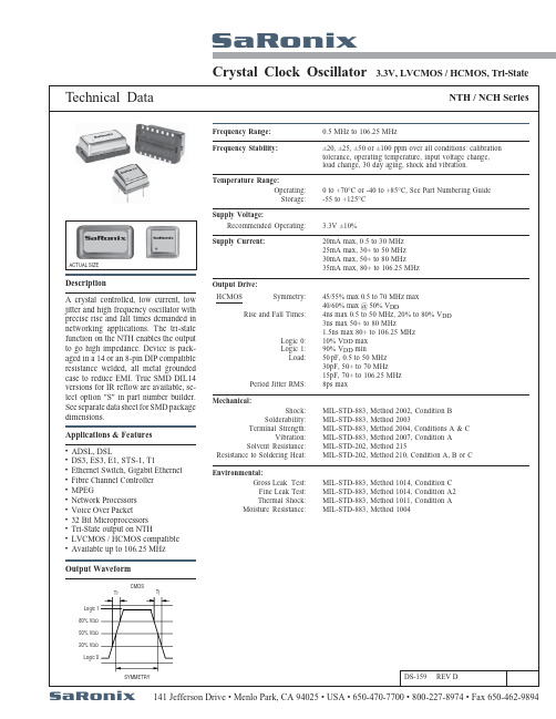
NTH / NCH SeriesSaRonixCrystal Clock OscillatorTechnical Data3.3V, LVCMOS / HCMOS, Tri-State141 Jefferson Drive • Menlo Park, CA 94025 • USA • 650-470-7700 • 800-227-8974 • Fax 650-462-9894DS-159 REV DSymmetry:Rise and Fall Times:Logic 0:Logic 1:Load:Period Jitter RMS:0.5 MHz to 106.25 MHzFrequency Stability:Frequency Range:±20, ±25, ±50 or ±100 ppm over all conditions: calibrationtolerance, operating temperature, input voltage change,load change, 30 day aging, shock and vibration.Temperature Range:Operating:Storage:0 to +70°C or -40 to +85°C, See Part Numbering Guide-55 to +125°CSupply Voltage:Recommended Operating: 3.3V ±10%Supply Current:20mA max, 0.5 to 30 MHz25mA max, 30+ to 50 MHz30mA max, 50+ to 80 MHz35mA max, 80+ to 106.25 MHzACTUAL SIZEDescriptionA crystal controlled, low current, lowjitter and high frequency oscillator withprecise rise and fall times demanded innetworking applications. The tri-statefunction on the NTH enables the outputto go high impedance. Device is pack-aged in a 14 or an 8-pin DIP compatibleresistance welded, all metal groundedcase to reduce EMI. True SMD DIL14versions for IR reflow are available, se-lect option "S" in part number builder.See separate data sheet for SMD packagedimensions.Output Drive:45/55% max 0.5 to 70 MHz max40/60% max @ 50% V DD4ns max 0.5 to 50 MHz, 20% to 80% V DD3ns max 50+ to 80 MHz1.5ns max 80+ to 106.25 MHz10% V DD max90% V DD min50 pF, 0.5 to 50 MHz30pF, 50+ to 70 MHz15pF, 70+ to 106.25 MHz8ps maxHCMOSMechanical:Shock:Solderability:Terminal Strength:Vibration:Solvent Resistance:Resistance to Soldering Heat:MIL-STD-883, Method 2002, Condition BMIL-STD-883, Method 2003MIL-STD-883, Method 2004, Conditions A & CMIL-STD-883, Method 2007, Condition AMIL-STD-202, Method 215MIL-STD-202, Method 210, Condition A, B or CEnvironmental:Gross Leak Test:Fine Leak Test:Thermal Shock:Moisture Resistance:MIL-STD-883, Method 1014, Condition CMIL-STD-883, Method 1014, Condition A2MIL-STD-883, Method 1011, Condition AMIL-STD-883, Method 1004Applications & FeaturesADSL, DSLDS3, ES3, E1, STS-1, T1Ethernet Switch, Gigabit EthernetFibre Channel ControllerMPEGNetwork ProcessorsVoice Over Packet32 Bit MicroprocessorsTri-State output on NTHLVCMOS / HCMOS compatibleAvailable up to 106.25 MHz•••••••••••Output WaveformT r T fCMOSLogic 180% V DD50% V DD20% V DDLogic 0SYMMETRYSaRonixSaRonixSaRonixCrystal Clock Oscillator3.3V, LVCMOS / HCMOS,141 Jefferson Drive • Menlo Park, CA 94025 • USA • 650-470-7700 • 800-227-8974 • Fax 650-462-9894SaRonixTrue SMD Adaptor - 7.57mm HighSaRonix 141 Jefferson Drive • Menlo Park, CA 94025 • USA • 650-470-7700 • 800-227-8974 • Fax 650-462-9894。
日本金属材料牌号表示方法
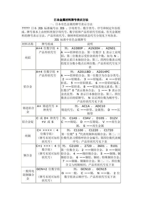
日本金属材料牌号表示方法一、日本有色金属的牌号表示方法????? 日本JIS 标准编号由JIS 、字母类号、数字类号、序号和制定年份组成。
牌号基本上由材料类别字母代号、数字组和产品形状代号组成。
有关金属材料的牌号表示方法、产品形状代号、铜材和铝材的状态代号分别见下列各表。
有色金属产品形状代号及名称铜和铜合金状态代号及名称铝和铝合金热处理状态代号及名称(也适用于镁合金)有色金属及其合金牌号(代号)有色金属加工产品状态代号表示方法二、日本黑色金属的牌号表示方法?? 1.日本(JIS )钢铁牌号表示方法简介?? 1.1 日本钢铁牌号表示方法概述?大约是在1949 年以前,日本钢铁牌号是按JES 标准规定表示的,现行钢铁牌号是按JIS 标准规定表示的。
? JIS (Japanese Industrial Sandard )是日本工业标准的代号。
日本钢铁牌号表示方法,在JIS 工业标准中没有专门的标准,在各类标准中出现的牌号有其特点是:有仅能表示出钢类,同时也可表示出钢材种类,有的还可表示出用途等。
? 牌号一般由三部分组成。
? 第一部分为前缀字母S 表示钢(Steel ),F 表示铁(Ferrum )。
? 第二部分采用英文字母或假名拼音的罗马字母,表示用途、钢材种类及铸锻件制品等。
如SC 为铸钢,FC 表示灰铸铁等。
K 表示工具,U 表示特殊用途。
有时用两个或几个字母组合起来表示钢的品种和类别,如SKS 表示合金工具钢(其中的一种)、SUJ 表示高碳铬轴承钢,SNCM 表示Ni —Cr —Mo钢等。
? 第三部分为数字,用来表示钢类或钢材序号或坑拉强度最低值(≥××× MPa )如SS400 表示碳素结构钢,其最低抗拉强度值为400Mpa 。
在牌号组成主体之后,根据需要,有时附加表示钢材形状、制造方法及热处理等的后缀字母,以示区别。
?? 1.2 各类钢牌号表示方法?? 1.2.1 普通结构钢牌号表示方法? SS ×××普通结构钢的牌号。
日本金属材料牌号表示方法
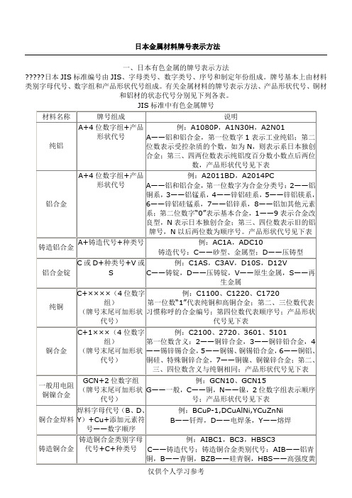
日本金属材料牌号表示方法一、日本有色金属的牌号表示方法?????日本JIS标准编号由JIS、字母类号、数字类号、序号和制定年份组成。
牌号基本上由材料类别字母代号、数字组和产品形状代号组成。
有关金属材料的牌号表示方法、产品形状代号、铜材和铝材的状态代号分别见下列各表。
有色金属产品形状代号及名称铜和铜合金状态代号及名称有色金属加工产品状态代号表示方法的品种和类别,如SKS表示合金工具钢(其中的一种)、SUJ表示高碳铬轴承钢,SNCM表示Ni—Cr—Mo钢等。
?第三部分为数字,用来表示钢类或钢材序号或坑拉强度最低值(≥×××MPa)如SS400表示碳素结构钢,其最低抗拉强度值为400Mpa。
在牌号组成主体之后,根据需要,有时附加表示钢材形状、制造方法及热处理等的后缀字母,以示区别。
??1.2各类钢牌号表示方法??1.2.1普通结构钢牌号表示方法?SS×××普通结构钢的牌号。
第一个S表示钢(Steel),第二个S表示结构的(Structural),×××表示抗拉强度最低值(×××MPa),JISG3101标准中有SS330、SS440、SS490和SS540四种牌号。
?焊接结构用碳素钢用SM490A 等表示牌号,M 代表中碳,后缀A 表示质量等级。
JISG3106标准中有400、490、520和570四个强度等级的多个牌号。
前三个等级的钢仅控制P 、S 含量,后一个强度等级的钢尚需控制C 和Mn 的含量。
Y 表示抗拉强度相同的钢,屈服点值略高于同类牌号的钢,除后缀A 外,尚可加后缀B 、C 。
??1.2.2机械制造用结构钢牌号表示方法?这类钢包含了我国的优质碳素结构钢和合金结构钢,下面介绍碳含量的数字代号。
?结构钢牌号后面两位数字表示碳含量表示百分数平均值×1002,小数点数字全部略去取整数。
