IP101-LF-DS-R08-07042005
WY8S8003系列ISP用户手册说明书
WY8S8003系列ISP用户手册Ver1.0.1上海维安半导体有限公司Wayon Semiconductor Co.,Ltd.目录1.概述 (1)1.1.软件简介 (1)1.2.MCU与下载盒连接示意图 (1)1.3.ISP升级流程 (2)1.3.1.一键下载 (2)1.3.2.普通下载 (7)2.通信协议 (11)2.1.命令列表 (11)2.2.串口协议格式 (11)2.2.1.下载命令请求协议定义 (11)2.2.2.下载命令回复协议定义 (12)2.3.指令说明 (12)2.3.1.CMD_SYNC (12)2.3.2.CMD_UPDATE_APROM (13)2.3.3.CMD_UPDATE_APROM_END (13)3.软件基本说明 (15)3.1.软件安装 (15)3.2.软件界面说明 (15)4.修订历史 (16)1. 概述ISP 是在系统编程的缩写,这个功能可以让用户在软件控制下,不需要将MCU 从产品上取下来进行应用程序升级。
针对8051 MCU 产品,我们通过串口提供ISP 升级方法,用户需要在LDROM 区域下载BOOT 程序。
将MCU 调试下载器或其他串口工具和MCU 相连接,并利用WayOn ISP Programer Tool 软件完成升级。
1.1.软件简介WayOn ISP Programer Tool 是维安半导体有限公司针对8051系列MCU 开发的ISP 下载工具,配合8051 MCU 调试器支持一键下载功能。
工具支持UART 通讯方式,默认采用38400的波特率,下载文件支持BIN/HEX 格式,BOOT 程序支持的串口管脚RXD 为引脚P04,TXD0为引脚P05,RST 引脚为P20。
维安8051 MCU 支持默认从APROM 启动,配合维安调试器的串口和GPIO 管脚连接目标MCU 串口和P20(P20配置为RST ),完成ISP 升级。
同时支持默认选择从LDROM 启动,利用普通串口连接目标MCU 串口,在上电启动周期(客户可配)之内完成升级启动完成ISP 升级。
KSZ8851-16MLL DEMO BOARD 48-PIN ETHERNET CONTROLLE

SD13
SD7 40
CPU_D14 3
6
SD14
SD8 39
CPU_D15 4
5
SD15
SD9 36
SD10 35
33
SD11 34
CPU_CMD
33
SD12 33
R10
SD13 32
CPU_CSN
33
SD14 31
R12
SD15 30
CPU_WRN
33
CMD
11
R14
CPU_RDN
33
CSN
12
R16
5 6 7 8
TANT
C27
R28 10uF
470pF 2.49K
Power 3.3V 0.1uF (red LED)
CSN CMD
4.7K R27 4.7K R29
GBLC03C_0 D3
GND 2 GND
VR 5 3.3VA
INTRN 4.7K R30
VOUT = 1.24 X [ 1 + ( 2.49k/ 1.5K ) ]
5
4
3
KSZ8851-16MLL (48-pin) Demo Board Black Diagram
D
Headers 20x2
RJ45
LAN1 T
KSZ8851-16MLL
Reset
Power
+1.8V
+2.5V
+3.3V
STATUS LEDs
OSC
EEPROM
C
MIC5209YM
25 MHz
AT93C46
x2
2
1
DATE:
IP113CLF原厂资料

10 /100Base-Tx/Fx Media ConverterFeaturesA 10/100BASE-TX/ 100BASE-FX converter Built in a 10/100BASE-TX transceiverBuilt in a PHY for 100BASE-FXBuilt in a 2-port switch– Pass all packets without address andCRC check (optional)– Supports modified cut-through frameforwarding for low latency– Supports pure converter mode dataforwarding for extreme low latency – Supports flow control for full and halfduplex operation– Bandwidth control– Forward 1600 bytes packet formanagement– Optional forward fragmentsBuilt in 128Kb RAM for data bufferSupports auto MDI-MDIX functionSupports link fault pass through functionSupports far end fault functionLED display for link/activity, full/half, 10/100 Built in a watchdog timer to monitor internal switch errorSupports EEPROM Configuration0.25u CMOS technologySingle 2.5V power supply48-pin LQFP packageSupport Lead Free package (Please refer to the Order Information) General DescriptionIP113C LF can be a 10/100BASE-TX to 100BASE-FX converter. It consists of a 2-port switch controller, a fast Ethernet transceiver and a PHY for 100BASE-FX. The transceivers in IP113C LF are designed in DSP approach with advance 0.25-um technology; this results in high noise immunity and robust performance.IP113C LF not only supports store and forward mode, it also supports modified cut through mode and pure converter mode for low latency data forwarding. IP113C LF can transmit packet(s) up to 1600 bytes to meet requirement of extra long packets.IP113C LF supports IEEE802.3x, collision base backpressure, and various LED functions, etc. These functions can be configured to fit the different requirements by feeding operation parameters via EEPROM interface or pull up/down resistors on specified pins.Block DiagramRevision HistoryRevision # Change DescriptionIP113C LF-DS-R01 Initial release.IP113C LF-DS-R02 Remove Operation Junction Temperature.IP113C LF-DS-R03 TP port should be linked at 100M full duplex when working at this mode.IP113C LF-DS-R04 Add the order information for lead free package.IP113C LF-DS-R05 Revise the diagram.IP113C LF-DS-R06 TP_FORCE (Pin24) &X_EN(Pin29)It is an input pin during reset period. The default value is latched at the end of reset. IP113C LF-DS-R07 Remove internal pull-high resistance & pull-low resistance on page 5.Modify the IPL : pull-low and IPH : pull-highIP113C LF-DS-R08 Add Power Pin description on Page10Application DiagramApplicationsUn-managed converter10B A S E_T/100B A S E-TX100B A S E-F XPIN DiagramN CF A S T _F W DG N D R X IP L F PG N D A 1A V C C G N D T X O M A V C C R X IM F X R D M D I R E C T _W I R E V C C F X S D F X T D P F X T D M N CT S M R E S E T B T S E X _E N L E D _F X _F E F _D E T / D U P L E X _M O D E L E D _T P _F D X L E D _T P _L IN KL E D _F X _L IN K / F X _F U L L L E D _F X _S D / S P E E D _M O D EV C C X 2G N D V C C O S C I S D A S C L / A 0N C V C C B G R E SV C C _IO G N D _IO G N DL E D _F X _F D X / A 2T X O P F X R D P A V C C N CT P _F O R C EL E D _T P _S P D1. PIN DescriptionType DescriptionpinI InputpinO OutputIPL Input pin with internal pull-low resistor.IPH Input pin with internal pull-high resistor.Pin no. Label Type DescriptionTransceiver5, 6 RXIP, RXIM I TP receive8, 9 TXOP, TXOM O TP transmit2 BGRES OBand gap resistorIt is connected to GND through a 6.19k (1%) resistor inapplication circuit.18 FXSD I100Base-FX signal detectFiber signal detect. It is an input signal from fiber MAU.Fiber signal detect is active if the voltage on FXSD is higherthan the threshold voltage, which is 1.35v ±5% when VCCis equal to 2.5v.13, 14 FXRDP, FXRDM I Fiber receiver data pairCommon-mode voltage of FXRDP and FXRDM aresuggested to near 0.5x AVCC.When voltage peak-to-peak>0.1V,FXRX could beworkable.16, 17 FXTDP, FXTDM O Fiber transmitter data pairFXTX with the external 100Ωresistor.Common-mode voltage of FXTDP and FXTDM aresuggested to near 0.5x AVCC.Swing of Voltage ≧ 0.8V.1. PIN Description (continued)Pin no. Label Type DescriptionLED pins31 LED_TP_LINK OTP port link LEDOn: link ok, Off: link fail, Flash: link ok & activity(Flash: on for 20ms and off for 80ms)33 LED_TP_SPD OTP port speed LEDOn: 100M, Off: 10M32 LED_TP_FDX OTP port full duplex LEDOn: full, Off: half,Flash: half & collision happens(Flash: on for 20ms and off for 80ms)36 LED_FX_LINK OFiber port link LEDOn: link ok, Off: link fail, Flash: link ok & activity(Flash: on for 20ms and off for 80ms)37 LED_FX_FDX OFiber port full duplex LEDOn: full, Off: half, Flash: half & collision happens(Flash: on for 20ms and off for 80ms)38 LED_FX_SD Fiber port signal detectOn: fiber signal detected, Off: fiber unplugged30 LED_FX_FEF_DETOFar end fault pattern receivedFor End Fault Patterns ReceiveLED On: 80ms, LED Off: 20msFor End Fault Pattern not ReceiveLED always OffNote: The output of LED pin is logic low when the LED is on.1. PIN Description (continued)Pin no. Label Type DescriptionMC operation mode29 X_EN O/IPH IEEE 802.3X enable on TP port and fiber port1: enable (default),0: disableIt is an input pin during reset period. The default value islatched at the end of reset.After reset, it becomes an output pin for testing.It should be connected to GND through a 1k ohm resisterto set 0.24 TP_FORCE O/IPL Local TP port auto negotiation enable1: TP port supports auto-negotiation with limited capabilitydefined in SPEED_MODE and DUPLEX_MODE.0: TP port supports auto-negotiation with 10M/100M, full/half capability (default)The default value may be updated by either programmingEEPROM register 3.5 or MII register 20.13.It is an input pin during reset period. The default value islatched at the end of reset.After reset, it becomes an output pin for testing.It should be connected to VCC through a 1k ohm resisterto set 1.38 SPEED_MODE IPHLocal TP port speed1: TP port has the 100Mb speed ability0: TP port has the 10Mb speed ability onlyIt is valid only if TP_FORCE is enabled.IPH30 DUPLEX_MODELocal TP port duplex1: TP port has the Full duplex ability0: TP port has the Half duplex ability onlyIt is valid only if TP_FORCE is enabled.36 FX_FULL IPHSet the duplex of fiber port1: full duplex (default)0: half duplex1. PIN Description (continued)Pin no. Label Type Description MC operation mode1. PIN Description (continued)Pin no. Label Type DescriptionMC operation mode21 LFP IPLLink fault pass through (LFP)1: enableLink status of one port is forwarded to the other port.0: disable (default)22, 23 DIRECT_WIRE,FAST_FWDIPL DIRECT_WIREFAST_FWD Function0 0 Store and forward switch mode(default)0 1 Modified cut-through switchmode1 0 Converter mode1 1 Converter mode withauto-change-forward functionStore and forward switch mode:IP113C LF will begin to transmit a frame right after thecompletion of receiving a frame.Modified cut-through switch mode:IP113C LF will begin to forward a frame after the first 64bytes data received. TP port should be forced at 100M atthis mode.Converter mode:Incoming frames are not buffered in IP113C LF to achievethe min latency. Both TP port and fiber port of IP113C LFshould work at 100M full duplex in this mode. If TP port islinked at half duplex, the total length of UTP cable and fibershould be less than 60 meters to meet the requirement ofCSMACD in IEEE802.3.Converter mode with auto-change-forward function:IP113C LF will change to forward mode if it detects thespeed is different in TP port and FX port.In converter mode, IP113C LF forwards IEEE802.3x pauseframe directly. In the other modes, IP113C LF doesn’tforward IEEE802.3x pause frame directly, it sends outpause frame when its internal buffer is full.1. PIN Description (continued)Pin no. Label Type DescriptionEEPROM interface45, 46 SDA, SCL IPH, O EEPROM interface37, 12, 46A[2:0] IPLPHY addressIP113C LF uses A[2:0] as EEPROM address to readEPROM.Pin no. Label Type DescriptionMisc.28 RESETB IResetIt is low active.41, 40 OSCI, X2 I, O Crystal pinsOSCI and X2 are connected to a 25Mhz crystal.If a 25MHz oscillator is used, OSCI is connected to theoscillator’s output and X2 should be left open.26, 27 TSM, TSE IPL Scan pinsThese two pins should be left open or connected to groundfor normal operation.Pin no. Label Type DescriptionPower1,7,11 AVCC 2.5VAnalogPower19,39,44 VCC 2.5V Digital Power34 VCC_IO 3.3V or 2.5V Digital Power35 GND_IO I/OGround4,10,20, 42,43 GNDGround2. Functional DescriptionData forwardingIP113C LF supports three types of data forwarding mode, store & forward mode, modified cut-through mode and pure converter mode. It can forward a frame despite of its address and CRC error. IP113C LF begins to forward the received data only after it receives the frame completely. The latency depends on the packet length.Modified cut-through modeIP113C LF begins to forward the received data when it receives the first 64 bytes of the frame. The latency is about 512 bits time width. The maximum packet length can be up to1600 bytes in this mode. Please refer to the pin description of FAST_FWD for configuration information.Pure converter modeIP113C LF operates with the minimum latency in this mode. The transmission flow does not wait until entire frame is ready, but instead it forwards the received data immediately after the data being received. Both transceivers are interconnected via internal MII signals, therefore the internal switch engine and data buffer are not used. Both TP port and fiber port of IP113C LF should work at 100M full duplex in this mode. If TP port is linked at half duplex, the total length of UTP cable and fiber should be less than 60 meters to meet the requirement of CSMACD in IEEE802.3.The packet length is not limited at this mode. Please see pin description of DIRECT_WIRE for configuration information.Fragment forwardingIP113C LF forwards CRC error packets but it will filter fragments when it works in modified cut-through mode. IP113C LF forwards fragments if user turns on bit 3 of EEPROM register 2.TP port force modeThe TP port of IP113C LF can work at auto mode or force mode. The following table shows all of the combination of its TP port.Link partner’s capabilityAN on AN off{TP_FORCE,IP113C LF’s link result100F100H10F10H100F 100H 10F10H SPEED_MODE,DUPLEX_MODE} IP113C LF’s capability011 100/10M, Full/Half, AN on 100F100H10F10H100H 100H 10H10H 010 100/10M, Half, AN on X 100H X 10H100H 100H 10H10H 001 10M, Full/Half, AN on X X 10F10H100H 100H 10H10H 000 10M, Half, AN on X X X 10H100H 100H 10H10H 111 100M, Full, AN on 100F X X X 100F 100F X X 110 100M, Half, AN on X 100H X X 100H 100H X X 101 10M, Full, AN on X X 10F X X X 10F10F 100 10M, Half, AN on X X X 10H X X 10H10H Note:AN on: with auto-negotiation capabilityAN off: without auto-negotiation capability100F: 100M full duplex100H: 100M half duplex10F: 10M full duplex10H: 10M half duplexLink fault pass throughWhen link fault pass through function is enabled, link status on TX port will inform the FX port of the same device and vice versa. From the link fault pass through procedure illustrates in the figure below, if link fail happens on IP113C LF’s TX port (1), the local FX port sends non-idle pattern to notice the remote FX port (2). The remote FX port then forces its TX port to link failed after receiving the non-idle pattern (4). In other words, this mechanism will alert the link fault status of local TX port to the remote converter’s TX port, and the link status of the remote TX port will become off. Link status LED will also be off for both IP113C LF and its link partner.(1) TP port link failedThe procedure of link fault pass through(3) fiber port gets remote link fault information (4) TP link fail(5) remote TPlink is offnon-idle patternNormal caseLED SW1LED_TP_LINK1LED_FX_LINK1LEDSW2localremote LED_FX_LINK2LED_TP_LINK2Link LED onSW1LED_TP_LINK1 LED_FX_LINK1LED_FX_LINK2LED_TP_LINK2Link LED onSW2ON ON ON ON ON ONRemote TP port disconnectedIP113C LF IP113C LFFiberSwitch1Switch2 LED SW1LED SW2local remote LED_TP_LINK1LED_FX_LINK1LED_FX_LINK2LED_TP_LINK2UTPUTPdisconnectLink LED onSW1 LED_TP_LINK1 LED_FX_LINK1LED_FX_LINK2LED_TP_LINK2Link LED onSW2Off Off Off Off Off OffFX port disconnectedIP113CLF IP113CLFUTP UTFiber P Switch1 Switch2LEDSW1LED_TP_LINK1LED_FX_LINK1LEDSW2localremoteLED_FX_LINK2LED_TP_LINK2Link LED onSW1 LED_TP_LINK1 LED_FX_LINK1LED_FX_LINK2LED_TP_LINK2Link LED onSW2Off Off Off Off Off OffLED diagnostic functions for fault indicationLED_TP_LINK LED_FX_LINK LED_FX_SD LED_FX_FEF_DET Status On On On Off Linkok Flash Flash On Off Link ok & activityOff Off On Off Remote TP link offOff Off Off Off Fiber RX off, Fiber TX/ RX offOff Off On Flash FiberTXoff NoteFlash: flash, period 100 msLink fault pass through is enabled.EEPROM – store the initial valueIP113C LF supports two ways to load initial value of MII registers. The procedure is illustrated as below.1. IP113C LF reads the default setting of MII register from pins2. IP113C LF updates the default setting of MII by reading EEPROM. If there exists an EEPROM3. After reading EEPROM, IP113C LF is virtually isolated from the EEPROM. Micro-controller can program both MII register and EEPROM.4. IP113C LF reloads the content of EEPROM to recover the value in MII registers programmed by Micro-controller after power on reset.Auto MDI_MDIXIP113C LF supports auto MDI-MDIX. It is always enabled. The following is its application circuit for auto MDI-MDIX.GND GNDIP113C LF's application circuit (auto MDI-MDIX on)EEPROM registersType Description Type Description R/W Read/Write RC Read and ClearSC Self-Clearing LL LatchingLow RO Read Only LH Latching HighPin(1) The default value is “1” and it dependson the setting of its corresponding pin.Pin(0) The default value is “0” and it dependson the setting of its corresponding pin.ROM NAME R/W DESCRIPTION DEFAULT EEPROM enable register 00[7:0] --EEPROM enable register 0This register should be filled with 55. IP113C LFwill examine the specified pattern to confirm ifthere is a valid EEPROM.55hROM NAME R/W DESCRIPTION DEFAULT EEPROM enable register 11[7:0] --EEPROM enable register 1This register should be filled with AA. IP113C LFwill examine the specified pattern to confirm ifthere is a valid EEPROM. The initial setting isupdated with the content of EEPROM only if thespecified pattern 55AA is found.AAhEEPROM registers (continued)ROM NAME R/W DESCRIPTION DEFAULT Switch configuration register 12.0 reserved -- The default value must be adopted for normaloperation.2.1 direct_wire -- Please see pin description of DIRECT_WIRE formore detail information.Pin (0)2.2 fast_fwd -- Please see pin description of FAST_FWD for moredetail information.Pin (0)2.3 mg_pass_fragment_en -- Pass fragment packet (>7B and <64B)1: pass fragment0: not pass fragment2.4 mg_col16_drop_en -- Collision 16 times drop enable1: drop0: not drop2.5 mg_col_backoff_en -- Collision back-off enable1: back after collision0: not back off after collision12.6 reserved --Thedefaultvalue must be adopted for normaloperation.2.7 p01_mg_backpress_en -- TP port backpressure control enable for halfduplex1: backpressure enable0: backpressure disable1 3.0 reserved --Thedefaultvalue must be adopted for normaloperation.0 3.1 reserved --Thedefaultvalue must be adopted for normaloperation.3.2 reserved -- The default value must be adopted for normaloperation.1 3.3 reserved --Thedefaultvalue must be adopted for normaloperation.1 3.4 mg_em_bist_en --SSRAM BIST enable (R/W by EEPROM only)1: BIST enable0: bypass BIST13.5 tp_force -- This pin overwrites the setting on pin 26TP_FORCE.Pin (0)3.6 mg_receive_en -- TP receive enable1: TP port can receive packet0: TP port drop all received packet1 3.7 reserved --Thedefaultvalue must be adopted for normaloperation.ROM NAME R/W DESCRIPTION DEFAULT Switch configuration register 2port allocated memory pages120d 4[7:0] p01_mg_port_page_no -- TPThe default is 120 pages with 64 bytes per page.120dport allocated memory pages5[7:0] p02_mg_port_page_no -- FXThe default is 120 pages with 64 bytes per page.Note: p01_mg_port_page_no adds p02_mg_port_page_no must be equal to 240.EEPROM registers (continued)ROM NAME R/W DESCRIPTION DEFAULT Local MC extended registervalue must be adopted for normaldefault6.0 reserved --Theoperation.value must be adopted for normaldefaultThe6.1 reserved --operation.6.2 p01_mg_auto_neg_en -- TP port auto-negotiation enable11: TP auto-negotiation enable0: TP auto-negotiation disable16.3 p01_mg_speed_mode -- TP port speed selection1: 100M, 0:10M6.4 p01_mg_duplex_mode -- TP port duplex mode selection11: full duplex, 0:half duplex16.5 p01_mg_flow_ctrl_en -- TP port flow control selection1: on, 0:offdefaultvalue must be adopted for normalThe6.6 reserved --operation.flow control/backpressure enablePin (1)port6.7 p02_mg_flow_ctrl_en -- Fiber1: enable, 0: disable17.0 p02_mg_duplex_mode -- Fiber port duplex mode (FX_FULL)1: full duplex, 0:half duplex7.1 reserved -- The default value must be adopted for normal1operation.7.2 reserved -- The default value must be adopted for normaloperation.7[4:3] p01_mg_throttle_confg -- TP port input Rate Control002'b00: full speed2'b01: 1/4 speed2'b10: 2/4 speed2'b11: 3/4 speed7[6:5] p01_mg_throttle_confg -- TP port output Rate Control002'b00: full speed2'b01: 1/4 speed2'b10: 2/4 speed2'b11: 3/4 speed17.7 mg_link_pass_en -- Link Fault Pass through enable (LFP)1: enable, 0: disable3. Signal RequirementsAbsolute Maximum RatingStresses above those listed under Absolute Maximum Ratings may cause permanent damage to the device. Functional performance and device reliability are not guaranteed under these conditions. All voltages are specified with respect to GND.Supply Voltage –0.3V to Vcc+0.3VInput Voltage –0.3V to Vcc+0.3VOutput Voltage –0.3V to Vcc+0.3VStorage Temperature -55°C to 125°CAmbient Operating Temperature (Ta) 0°C to 70°CDC CharacteristicOperating ConditionsParameter Sym. Min. Typ. Max. Unit Conditions Supply Voltage VCC 2.375 2.5 2.625VPower Consumption 0.475 WVCC=2.5v Input ClockParameter Sym. Min. Typ. Max. Unit Conditions Frequency 25 MHzFrequencyTolerance -100 +100PPMI/O Electrical CharacteristicsParameter Sym. Min. Typ. Max. Unit Conditions Input Low Voltage VIL 0.8 VInput High Voltage VIH 2.0 VOutput Low Voltage VOL 0.4 V IOH=4mAOutput High Voltage VOH VCC_IO-0.4VIOL=4mA4. Order InformationPart No. Package NoticeIP113C48-PIN LQFP -IP113C LF 48-PIN LQFP Lead free5. Package Detail132425363748Notes:1. DIMENSION D & E DO NOT INCLUDE MOLD FLASH OR PROTRUSION.2. DIMENSION b DOES NOT INCLUDE DAMBAR PROTRUSION / INTRUSION.3. MAX. END FLASH IS 0.15MM.4. MAX. DAMBAR PROTRUSION IS 0.13MM.GENERAL APPEARANCE SPEC SHOULD BE BASED ON FINAL VISUAL INSPECTION SPEC.IC Plus Corp.ACTION DYNAMIC TECH(HK) TRADING COMPANYadd:Room1139-1142,Guoli Building,ZhenzhongRoad,Futian District,Shenzhen,China Tel:86-755-82539044 82539193Faxÿ86-755-82539160E-mail:DNSJ@。
石家庄陆杰电子科技有限公司 Wi-Fi通信模块使用说明说明书
Wi-Fi通信模块使用说明石家庄陆杰电子科技有限公司版本:20230309V1.1基本说明感谢您购买了陆杰Wi-Fi通信模块(WiFi-UART)。
本手册主要介绍Wi-Fi通信模块(WiFi-UART)使用内容。
在使用产品之前,请仔细阅读本手册,并在充分理解手册内容的前提下,进行使用软件及硬件方面的介绍,请查阅相关手册。
用户须知手册等其他技术资料中所列举的示例仅供用户理解、参考用,不保证一定动作。
将该产品与其他产品组合使用的时候,请确认是否符合有关规格、原则等。
使用该产品时,请自行确认是否符合要求以及安全,对于本产品故障而可能引发机器故障或损失时,请自行设置后备及安全功能。
责任申明手册中的内容虽然已经过仔细的核对,但差错难免,我们不能保证完全一致。
我们会经常检查手册中的内容,并在后续版本中进行更正,欢迎提出宝贵意见。
手册中所介绍的内容,如有变动,请谅解不另行通知。
联系方式如果您有任何关于本产品的使用问题,请与购买产品的代理商、办事处联系,也可以直接与陆杰公司联系。
电话:400-657-7769*************地址:石家庄栾城区邵家庄工业路2号邮编:050000网址:/未经明确的书面许可,不得复制、传翻或使用本资料及其中的内容,违者要对造成的损失承担责任。
保留包括实用模块或设计的专利许可及注册中提供的所有权力。
二零二二年六月目录一、基本说明 (4)二、硬件设备说明 (4)三、连接方式说明 (5)四、配置软件说明 (5)五、操作说明 (6)六、微信小程序使用说明 (7)七、故障排除 (10)一、基本说明Wi-Fi通信模块(Wi-Fi-UART)(以下简称模块)具备USB转232、转485、转422、串口转Wi-Fi的功能,适用PLC、HMI等串口设备的读写监控,数据传输功能。
1)通过WiFi-UART配置软件PC端或微信小程序,可以配置模块接入互联网,实现远程数据透传。
2)通过USB接口,插入电脑,可以实现USB转232(485,422)功能。
武汉南瑞供货清单
交流阻抗测试仪
测试项目
1、电流;
2、电压;
3、阻抗;
4、功耗;
主要技术参数
1、电流测量范围:100mA~50A;
2、电流测量准确度:±0.5%读数±1mA;
3、电压测量范围:5V~500V;
4、电压测量准确度:±0.5%读数±0.01V;
5、采样率: 2000点/周波(电压、电流各1000点);
4、行程测试范围:6mm~1000mm(由传感器的长度决定);行程最小分辨率:0.1mm;测试准确度为:±1.0%读数±0.1mm(滑线电阻传感器);
5、仪器电源输入:AC220V±10%;50Hz±1Hz;
6、直流操作电源输出:电压20V~250V可调,电流20A,数字程控调整。
3
GKC-6B
高压开关
5、直流操作电源输出:电压20V~250V可调,电流20A,数字程控调整。
2
GKC-6
高压开关
动态性
测试仪
测试项目
1、时间:触摸操作完成各类开关固有分、合闸时间、相间同期、相内同期和所有断口同期;
3、2、重合闸:一次性测量金属短接时间(合—分)、无电流间隔时间(分—合)及
(分—合—分、合—分—合);
2、特征数据、波形同屏显示。
3、多种电压基准信号取样方式:
(1)有线方式:从PT端计量绕组取信号,数字信号有线传输。
(2)无线方式:从PT端计量绕组取信号,数字信号无线传输,省去电缆长距离连接。
(3)无电压方式:不需要从PT端子取信号,采用软件计算的方式找到电压基准。
技术指标
1、仪器电源输入:220V、50Hz或内部电源。
电流:全电流>100μA时: ±5%读数±1个字;
Aolynk-S1508LV100R004版本说明书

Aolynk S1508LV100R004版本说明书杭州华三通信技术有限公司Aolynk S1508LV100R004版本说明书关键词:Logo切换摘要:此版本系Logo切换版本缩略语:缩略语英文全名中文解释VLAN Virtual Local Area Network 虚拟局域网ServiceofQoS Quality服务质量目录1 版本信息 (4)1.1 版本号 (4)1.2 历史版本信息 (4)1.3 版本配套表 (4)2 版本使用限制及注意事项 (4)3 版本特性说明 (5)3.1 版本硬件特性 (5)3.2 版本软件特性 (5)4 版本变更说明 (5)4.1 特性变更说明 (5)4.2 命令行变更说明 (5)4.3 MIB变更说明 (5)4.4 操作方式变更说明 (5)5 存在问题与规避措施 (6)6 解决问题列表 (6)7 配套资料 (6)7.1 配套资料清单 (6)7.2 配套产品资料的获取方法 (6)8 版本升级操作指导 (6)表目录表1 历史版本信息表 (4)表2 版本配套表 (4)表3 特性变更说明 (5)表4 配套手册清单 (6)表5 从网站查询和下载资料的说明 (6)1 版本信息1.1 版本号版本号:S1508LV100R0041.2 历史版本信息表1历史版本信息表版本号基础版本号发布日期备注S1508LV100R004S1508LV100R0032007-05-16无S1508LV100R003S1508LV100R0012006-09-30无S1508LV100R001首次发布2006-04-29无1.3 版本配套表表2版本配套表系列以太网交换机产品系列 AolynkS1500型号S1508L内存需求无FLASH需求无BOOTROM版本号无目标文件名称S1508LV100R004.exeQUIDVIEW版本号无CAMS版本号无WEB版本号无备注无2 版本使用限制及注意事项无3 版本特性说明3.1 版本硬件特性无3.2 版本软件特性无4 版本变更说明4.1 特性变更说明表3特性变更说明版本号项目描述硬件特性更新无S1508LV新增特性:100R004软件特性更新显示配置:增加显示当前配置按钮。
IP101单端口快速以太网收发器(中文版)
10/100M单端口快速以太网收发器特性●10/100Mbps的TX●全双工或半双工●支持自动的MDI/MDIX(介质相关交叉)功能●完全符合IEEE●支持IEEE 自动协商●支持MII / RMII / SNI接口●IEEE 全双工控制规范●支持自动省电模式●支持基线漂移(BLW)补偿●支持中断功能●支持中继模式●内置的调节器提供电源●基于DSP的PHY收发器技术●使用25MHz的晶体振荡器或50MHz振荡的ref_clk信号作为时钟源●灵活的LED显示速度、双工、链接、活动和碰撞状态●通过 MDC和MDIO与其他MAC通信时支持流量控制● CMOS技术,●48引脚LQFP封装●支持无铅封装(请参阅订单信息)一般说明IP101A LF是一个IEEE 兼容的单端口10/100Mbps快速以太网收发器。
它支持自动的MDI/MDIX功能以简化网络安装和减少系统维护成本。
为了提高系统的性能,IP101A提供了一个硬件中断引脚指示链接、速度和双工状态的变化。
IP101A还提供媒体独立接口(MII)/串行网络接口(SNI)或简化媒体独立接口(RMII)连接不同类型的10/100Mbps的媒体访问控制器(MAC)。
IP101A LF设计使用5类非屏蔽双绞线电缆连接到其它局域网设备。
IP101A LF收发器是用先进的CMOS技术制造的,该芯片只需要的电源并在自动节能模式消耗非常低的功率。
IP101A LF可以实现网络用双绞线RJ-45接口适配器连接。
它也可以很容易地实现集线器、交换机、路由器、接入点。
特性总则目录修订历史接收和发送数据的路径框图引脚定义1引脚描述2寄存器描述3功能描述4串行管理界面5晶体规格6布局准则7电气特性直流特性7.1.1绝对最大额定值7.1.2功率消耗7.1.3操作条件7.1.4电源电压交流特性7.2.1 MII定时时序7.2.2 RMII定时时序7.2.3 SMI定时时序8订单信息9封装和机械规范接收和发送数据的路径框图图1:IP101A LF的流程图引脚配置图2:IP101A LF引脚分配1、引脚描述2、寄存器描述注意:Register 2和register 3标识寄存器一起构成供应商模型、模型版本号和组织唯一标识符(OUI)信息。
R800系列产品介绍

故障类 型
故障点 1
保护方式
LSP1:1 PW冗余+VPN-FRR LSP1:1 VPN-FRR+VRRP IP-FRR+VRRP
保护路径 A-C-E-D-F-H-RNC A-C-E-G-I-H-RNC A-B-D-E-G-I-H-RNC A-B-D-E-G-I-RNC A-B-D-F-H-I-RNC
转发平面:在NP(业务接口盘)上完成数据转发查找。对业务数据进行 识别,终结,封装,单播,多播,丢弃等处理。对数据报文做性能统计。
控制平面:在RCU上完成。负责路由协议和MPLS协议的处理,管理路由 表和IP转发表以及标签转发表。
交换单元:在SCU(业务交换盘)上完成BFD,MPLS OAM。完成数据 的无阻塞交换,
IPRAN硬件架构
RCU
管理通道
管理平面
管理通道
信令通道
控制平面
信令通道
板间通信
数据平面
数据平面
数据平面
保护 QoS
OAM 时 钟
OAM 时 钟
保护 QoS
OAM 时 钟
业务盘
SCU
业务盘
IPRAN硬件架构
IPRAN硬件架构
管理平面:在RCU(路由控制单元)上完成。对设备进行配置管理、故 障管理、性能管理和安全管理并存储设备的管理信息。提供告警接口、 外部监控接口、F接口和f接口。控制系统智能风扇。
IP业务信号流处理
业务从UNI PPH PPH+LSP+PW+IP LSP+PW D+S IP
N P
S C U
D’+S’ PPH D’+S’+LSP+PW+IP LSP+PW
华为网络设备清单

LS-FM6U
6端口LANSWITCH百兆多模光接口模块(2 Km,SC)
1
汇聚交换机小计:46134
楼层交换机:Quidway S2026
LS-2026
S2026以太网交换机主机,24×10/100M TX,2 Slot
10
LS-3026-FMIU
1端口百兆多模光接口模块(2 Km,SC)
10
楼层交换机小计:75150
1
RT-NE-RSEU
路由交换扩展单元
1
RT-NE-VIUB
通用接口单元前处理板-256M内存
1
RT-NE-VIEU
通用接口扩展单元
1
RT-NE-8EPA
8端口E1/CE1接口前处理板卡
1
RT-NE-8EKA
8端口E1/CE1 75欧姆电接口后转接卡(DB68母座)
1
SWP-VRP
VRP FOR NE IP ENTERPRISE-NE08E/16E
网络设备清单
分局平台中心机房
高端路由器NE05产品描述
数量
CHASSIS-NE
B68路由器总装机柜
1
RT-NE16E CHASSIS/3AC
NE16E总装机箱(220VAC)
1
RT-NE-ALUA
系统监控管理单元
1
RT-NE-HAU
系统CPCI热插拔控制桥板
1
RT-NE-RSUB
路由交换单元前处理板-256M内存(少于20万条路由)
1
分局平台机房中心路由器小计:274455
分局平台中心机房:Quidway S3526E
ቤተ መጻሕፍቲ ባይዱLS-3526E
S3526E以太网交换机主机(220VAC),24×10/100M TX,2 Slot
楼层WiFi覆盖设备及技术要求

楼层WiFi覆盖设备及技术要求一、楼层WiFi覆盖设备名称、型号及数量二、楼层WiFi覆盖拓扑图三、公交大厦楼层平面图XX集团本次WLAN项目覆盖范围为20F-25F,每个楼层近800平方米,共6个楼层,每层设计使用4个AP,共计24个AP。
本次WLAN项目采用AC+POE交换机+AP 的组网方式。
AP供电及数据信号传送通过网线连接到一台48口POE 交换机,POE交换机设计装置在22F交换机室,方便与原来22F楼层交换机进行数据透传,22F楼层交换机连接到20F巴士集团计算机中心机房AC。
AC具有管理所有24个AP及用户接入AP功能,AC能分配管理400+的上网认证用户名及密码。
四、验收标准1、中标人应按采购方的指令,按批次将一套或多套设备运送至采购方指定的场地。
2、设备验收:设备及配件到场,按投标书要求由中标人提供设备清单,采购方根据投标书及设备清单对到场设备及配件的名称、型号、规格、数量等进行清点,并签字验收。
如不符合投标书要求,采购方不予签字验收,违约责任按中标合同相关条款执行。
3、项目验收:中标人完成设备的的安装、调试、开通、及人员培训,由中标人提供验收报告,交由采购方签字验收。
如不符合投标书要求,采购方不予签字验收,违约责任按中标合同相关条款执行。
4、如项目实施过程中无法按用户要求作出相应功能或服务的,或是按用户要求提交相关资料的,我方将拒绝或推迟验收。
五、售后服务需求1、免费保修期:设备提供三年原厂售后服务,其他货物免费质保期三年,时间自最终验收合格并交付使用之日起计算。
2、原厂服务:投标时提供设备原厂针对本项目的售后服务承诺函原件复印件,原件备查。
要求原厂质保的产品需能在厂商官网查询到该货物属于我单位的质保信息。
3、维修响应及故障解决时间:在保修期内,一旦发生质量问题,投标人保证在接到通知4小时内赶到现场进行修理或更换。
4、其他:投标人应按其投标文件中的承诺,进行其他售后服务工作。
H3C目录价
S001A03J H3C S9500 路由交换机S001A08M H3C S9500E 路由交换机S001A08J H3C S12500 路由交换机S001A06J H3C S7500E系列以太网交换机S101A23J H3C S7500系列-机柜0235A262LS-7500-N68-2.2m-AC H3C S7500 2.2m 交流总装机柜0235A263LS-7500-N68-1.8m-AC H3C S7500 1.8m 交流总装机柜0235A25U LS-7500-N68-2.2m-DC H3C S7500 2.2m 直流总装机柜0235A25V LS-7500-N68-1.8m-DC H3C S7500 1.8m 直流总装机柜S101A30Y H3C S7500E系列以太网交换机主机0235A25N LS-7510E H3C S7510E 以太网交换机主机0235A27Q LS-7506E H3C S7506E 以太网交换机主机0235A27S LS-7506E-V H3C S7506E-V 以太网交换机主机0235A27R LS-7503E H3C S7503E 以太网交换机主机0235A29A LS-7502E H3C S7502E 以太网交换机主机0235A33R LS-7503E-S H3C S7503E-S 以太网交换机主机0235A436LS-7506E-S H3C S7506E-S 以太网交换机主机S101A402H3C S7500E系列以太网交换机电源模块0231A79N LSQM1AC1400H3C S7500E 交流电源模块,1400W0231A79P LSQM1DC1400H3C S7500E 直流电源模块,1400W,支持PoE0231A79R LSQM1AC650H3C PSR650A 交流电源模块,650W0231A79S LSQM1DC650H3C PSR650D 直流电源模块,650W0231A88R LSQM1PWRSPA H3C S7500E 以太网交换机共享电源适配器模块0231A91B LSQM1AC300H3C S7502E 交流电源模块,300W0231A91F LSQM1AC6000H3C S7500E 交流电源模块,6000W0231A919LSQM1DC300H3C S7502E 直流电源模块,300WS101A403H3C S7500E系列以太网交换机引擎模块0231A73J LSQM1SRP2XB0H3C S7500E Salience VI-10GE交换路由引擎-自带两个万兆接口0231A73K LSQM1SRPB0H3C S7500E Salience VI交换路由引擎0231A73L LSQM1SRP1CB0H3C S7500E Salience VI-Turbo交换路由引擎0231A73S LSQM1MPUA0H3C S7502E 主控模块0231A861LSQM1MPUB0H3C S7500 Salience VI-Lite交换路由引擎0231A86P LSQM1SRPD0H3C S7500 Salience VI-Plus 交换路由引擎0231A90L LSQM1SRP12GB0H3C S7500E Salience VI-GE 交换路由引擎-附带12个千兆/百兆以太网光接口(SFP,L 0231A90E LSQM1CGP24TSC0H3C S7503E-S-交换路由引擎,提供24端口千兆/百兆以太网光口(SFP,LC),其中8端口可0231A0A4LSQM1SRPA0H3C S7506E-S Salience VI-Smart 专用交换路由引擎0231A99P LSQM1CGV24PSC0H3C S7503E-S-交换路由引擎,提供24端口千兆电接口(RJ45),其中4端口可光电复用(S S101A404H3C S7500E系列以太网交换机业务模块0231A76G LSQM1FV48SA0H3C S7500E 48端口百兆以太网电接口模块(PoE,RJ45)0231A76F LSQM1FP48SA0H3C S7500E 48端口百兆以太网光接口模块(SFP,LC)0231A76H LSQM1GV48SA0H3C S7500E 48端口千兆以太网电接口模块(PoE,RJ45)0231A80H LSQM1GV48SC0H3C S7500E 48端口千兆以太网电接口模块(PoE,RJ45)0231A76T LSQM1GT24SC0H3C S7500E 24端口千兆以太网电接口模块(RJ45)0231A76R LSQM1GP12EA0H3C S7500E 12端口增强型千兆以太网光接口模块(SFP,LC)0231A76S LSQM1GP24SC0H3C S7500E 24端口千兆/百兆以太网光接口模块(SFP,LC)0231A80V LSQM1GP48SC0H3C S7500E 48端口千兆/百兆以太网光接口模块(SFP,LC)0231A76Q LSQM1TGX2SC0H3C S7500E 2端口万兆以太网光接口模块(XFP,LC)0231A76U LSQM1P24XGSC0H3C S7500E 24端口千兆/百兆以太网光接口(SFP,LC)+2端口万兆以太网光接口( XFP 0231A76P LSQM1TGX1EA0H3C S7500E 1端口增强型万兆以太网光接口模块(XFP,LC)0231A76V LSQM1T24XGSC0H3C S7500E 24端口千兆电口(RJ45)+2端口万兆光口以太网接口(XFP,LC)模块0231A79J LSQM1GP12SC0H3C S7500E 12端口千兆/百兆以太网光接口模块(SFP,LC)0231A84J LSQM1PT16PSC0H3C S7500E-16端口千兆无源光网络接口(EPON OLT SFP,SC)+8端口千兆/百兆以太0231A84H LSQM1PT8PSC0H3C S7500E-8端口千兆无源光网络接口(EPON OLT SFP,SC)+8端口千兆/百兆以太网0231A84G LSQM1PT4PSC0H3C S7500E-4端口千兆无源光网络接口(EPON OLT SFP,SC)+8端口千兆/百兆以太网0231A832LSQM1FWBSC0H3C S7500E 防火墙业务板模块0231A81K LSQM1WCMB0S7500E 无线控制器业务板模块0231A90N LSQM1LBSC0H3C S7500E-千兆负载均衡业务模块0231A941NSQM1ACGM H3C iMC SecCenter组件-ACG Manager应用控制与审计管理系统-纯软件(CD)3130A27X LIS-ACG-APP H3C SecPath ACG2000-M/H3C SecBlade ACG-应用识别特征库升级服务-1年0231A90F LSQM1GP24TSC0H3C S7500E-24端口千兆/百兆以太网光接口模块(SFP,LC),其中8端口可光电复用0231A936LSQM1GV40PSC0H3C S7500E-40端口千兆电口(RJ45)+8端口千兆/百兆光口以太网接口模块(SFP,LC) 0231A942LSQM1NSMSC0H3C S7500E NetStream业务板模块0231A95K NSQM2TAS H3C iMC SecCenter组件-iTAS智能流量分析系统-纯软件(CD)3130A27D LIS-SBIPS-SA-1Y H3C SecBlade IPS,特征库升级-1年,病毒库升级-1年0231A95L NSQM1IPSM H3C iMC SecCenter组件-IPS Manager入侵防御管理系统-纯软件(CD)0231A93P LSQM1SSLSC0H3C S7500E SSL VPN业务板模块3130A27M LIS-S7500E-SSLVPN-1000H3C S7500E SSL VPN 1000个用户3130A27P LIS-S7500E-SSLVPN-5000H3C S7500E SSL VPN 5000个用户0150A124LS-LSQM1IPSSC0+1Y H3C 7500E-千兆入侵防御系统模块,含一年特征库升级,一年病毒库升级0231A0AE LSQM1TGX8SD0H3C S7500E 8端口万兆以太网接口模块(XFP,LC)0231A96F LSQM1GV48SD0H3C S7500E 48端口千兆以太网电接口模块(RJ45),PoE Plus0231A971LSQM1GP24TXSD0H3C S7500E 16端口千兆以太网光口(SFP,LC)+8端口千兆以太网Combo口+2端口万0231A975LSQM1GP24TSD0H3C S7500E 16端口千兆以太网光口(SFP,LC)+8端口千兆以太网Combo口模块0231A977LSQM1TGX4SD0H3C S7500E 4端口万兆以太网光接口模块(XFP,LC)0231A978LSQM1TGX2SD0H3C S7500E 2端口万兆以太网光接口模块(XFP,LC)0231A99M LSQM1GP48SD0H3C S7500E 48端口千兆以太网光接口模块(SFP,LC)0231A889LSQM1GP48EB0H3C S7500E 48端口增强型千兆以太网光接口模块(SFP,LC)0231A972LSQM1GP24TEB0H3C S7500E 16端口千兆以太网光口(SFP,LC)+8端口千兆以太网Combo口增强型模块0231A973LSQM1TGX4EB0H3C S7500E 4端口增强型万兆以太网光接口模块(XFP,LC)0231A974LSQM1TGX2EB0H3C S7500E 2端口增强型万兆以太网光接口模块(XFP,LC)0150A0A9LS-LSQM2ACGASC0+1Y H3C S7500E-应用控制网关业务板模块,含一年特征库升级8812A002SV-PS-TIM工程实施服务0231A0AG LSQM2FP48SA0H3C S7500E 48端口百兆以太网光接口模块(SFP,LC)0231A0AR LSQM2FT48SA0H3C S7500E 48端口百兆以太网电接口模块(RJ45)0231A0A5NSQM1FWM0H3C iMC SecCenter组件-Firewall Manager防火墙管理系统-纯软件(CD)0223A08B0231A562SFP-GE-SX-MM850-A光模块-SFP-GE-多模模块-(850nm,0.55km,LC)0231A563SFP-GE-LX-SM1310-A光模块-SFP-GE-单模模块-(1310nm,10km,LC)2312170SFP-GE-LH40-SM1310光模块-SFP-GE-单模模块-(1310nm,40km,LC)2312172SFP-GE-LH40-SM1550光模块-SFP-GE-单模模块-(1550nm,40km,LC)2312173SFP-GE-LH70-SM1550光模块-SFP-GE-单模模块-(1550nm,70km,LC)0231A321SFP-GE-LH100-SM1550光模块-SFP-GE-单模模块-(1550nm,100km,LC)0231A085SFP-GE-T电模块-SFP-GE-(RJ45)0231A453SFP-GE-LH70-SM1470-CW光模块-SFP-GE-单模模块-CWDM-(1470nm,70km,LC)0231A454SFP-GE-LH70-SM1490-CW光模块-SFP-GE-单模模块-CWDM-(1490nm,70km,LC)0231A455SFP-GE-LH70-SM1510-CW光模块-SFP-GE-单模模块-CWDM-(1510nm,70km,LC)0231A456SFP-GE-LH70-SM1530-CW光模块-SFP-GE-单模模块-CWDM-(1530nm,70km,LC)0231A449SFP-GE-LH70-SM1550-CW光模块-SFP-GE-单模模块-CWDM-(1550nm,70km,LC)0231A450SFP-GE-LH70-SM1570-CW光模块-SFP-GE-单模模块-CWDM-(1570nm,70km,LC)0231A451SFP-GE-LH70-SM1590-CW光模块-SFP-GE-单模模块-CWDM-(1590nm,70km,LC)0231A452SFP-GE-LH70-SM1610-CW光模块-SFP-GE-单模模块-CWDM-(1610nm,70km,LC)0231A38S SFP-GE-PX10-D-SM1490-A光模块-SFP-GE-单模-(1490nm(Transmit)/1310nm(Receive),10km,SC/PC)0231A11U SFP-GE-LX-SM1310-BIDI光模块-SFP千兆BIDI光模块-TX1310/RX1490,10km,LC0231A11V SFP-GE-LX-SM1490-BIDI光模块-SFP千兆BIDI光模块-TX1490/RX1310,10km,LC0231A320SFP-FE-SX-MM1310-A光模块-SFP 100M/155M-多模模块-(1310nm,2km,LC)0231A564SFP-FE-LX-SM1310-A光模块-SFP 100M/155M-单模模块-(1310nm,15km,LC)0231A089SFP-FE-LH40-SM1310光模块-SFP 100M/155M单模模块-(1310nm,40km,LC)0231A090SFP-FE-LH80-SM1550光模块-SFP 100M/155M单模长距模块-(1550nm,80km,LC)0231A494XFP-SX-MM850光模块-XFP-10G-多模模块-(850nm,300m,LC)对于62.5um MMF w/ 160MHz*km光纤,最大传输距离26M;对于50um MMF w/ 500MHz*km光纤,最大传输距离82M;27,000.00对于50um MMF w/ 2000MHz*km光纤,最大传输距离300M;0231A438XFP-LX-SM1310光模块-XFP-10G-单模模块-(1310nm,10km,LC)0231A41G XFP-LH80-SM1550光模块-XFP-10G-单模模块-(1550nm, 80km, LC)0231A72X XFP-LH40-SM1550-F1XFP万兆光模块(1550nm,40km,LC)0231A84D SFP-GE-PX20-D-SM1490-A SFP千兆模块-(1490nm(Transmit)/1310nm(Receive),20km,SC/PC)S101A405H3C S7500E系列以太网交换机PoE电源模块0231A48J LSBM1POEDIMMH PoE主从电源管理微电子组件0231A79Q LSQM1AC2800H3C S7500E 交流电源模块,2800W,PoES101A407H3C S7500E系列以太网交换机其他可选配件0601A001CF-1G存储介质-CF-1G0601A004CF-256M-I256M工业级CF卡0601A003CF-512M存储介质-CF-512MB(英文资料)S101A32W H3C S7500E系列-ONU 产品9801A08M LS-ET704-L4端口无源光网络单元(20km)9801A08R LS6M2PU1SB单千兆端口无源光线路接口单元模块B(20km)9801A09Y SOHO-ET254-L Aolynk ET254-L 4端口(10/100M-FE)无源光网络单元-SC接口9801A10A SOHO-ET254-L-AC60Aolynk ET254-L-AC60 4端口(10/100M-FE)无源光网络单元-SC接口(AC 60V)9801A10M SMB-ET716H3C ET716 无源光网络单元(16FE)-SC接口9801A10N SMB-ET724H3C ET724 无源光网络单元(24FE)-SC接口0223A00F分光器集合4501A000OC-1x32光分路器-单模-1×32均分-SC/PC4501A001OC-1x2-5:95光分路器-单模-1×2-5%&95%-SC/PC4501A002OC-1x2光分路器-单模-1×2均分-SC/PC4501A003OC-1x4光分路器-单模-1×4均分-SC/PC4501A004OC-1x16光分路器-单模-1×16均分-SC/PC4501A005OC-1x32-U光分路器-单模-1×32均分-SC/PC-1U盒子4501A006OC-1x8光分路器-单模-1×8均分-SC/PC4501A007OC-1x2-40:60光分路器-单模-1×2-40%&60%-SC/PC4501A008OC-2x32光分路器-单模-2×32均分-SC/PC4501A009OC-1x2-25:75光分路器-单模-1×2-25%&75%-SC/PCS001A07P H3C S7500E系列以太网交换机-组合报价项目集合0150A08F LS-Z+M2-2H3C S7502E主机+单主控+12口千兆光接口模块(SFP,LC)(EA)0150A08G LS-Z+M2-1H3C S7503E主机+单Salience VI-Turbo引擎+12口千兆光接口模块(SFP,LC)(SC) 0150A09X LS-Z+M3-1 4 PON口简配S7502E OLT促销包0150A0AM LS-Z-L4-B1H3C S7510E多业务应用交换机0150A0AN LS-Z-L4-B2H3C S7506E-V多业务应用交换机0150A0AP LS-Z-L4-B3H3C S7506E多业务应用交换机0150A0AQ LS-Z-L4-B4H3C S7503E-S多业务应用交换机S001A04L H3C S7500系列以太网交换机S001A04L H3C S7502以太网交换机S001A08G H3C S3600-2P-OLT 以太网交换机S001A08R H3C S5800系列以太网交换机S101A40D H3C S5800系列以太网交换机主设备0235A36R LS-5800-32C-PWR-H3H3C S5800-32C-PWR L3以太网交换机主机,支持24个10/100/1000BASE-T端口,支持0235A36T LS-5800-32C-H3H3C S5800-32C L3以太网交换机主机,支持 24个10/100/1000BASE-T端口,支持4个1 0235A36V LS-5800-60C-PWR-H3H3C S5800-60C-PWR L3以太网交换机主机,支持48个10/100/1000BASE-T端口,支持0235A372LS-5800-32F-H3H3C S5800-32F L3以太网交换机主机,支持24个100/1000BASE-X SFP端口,支持4个1 0235A376LS-5800-56C-PWR-H3H3C S5800-56C-PWR L3以太网交换机主机,支持48个10/100/1000BASE-T端口,支持0235A377LS-5800-56C-H3H3C S5800-56C L3以太网交换机主机,支持48个10/100/1000BASE-T端口,支持4个10 S101A40E H3C S5800系列以太网交换机端口扩展模块0231A93G LSWM1SP4P4端口万兆以太网SFP+光接口模块0231A93H LSWM1SP2P2端口万兆以太网SFP+光接口模块0231A93L LSWM1GT16P16端口10/100/1000BASE-T以太网电接口模块0231A93M LSWM1GP16P16端口100/1000BASE-X以太网光接口模块S101A40F H3C S5800系列以太网交换机业务扩展模块0231A93S LSWM148POEM H3C S5800-60C-PWR中功率PoE模块-PoE+模块插槽0231A94G LSWM1WCM10H3C S5800 系列-无线功能模块-OSM Slot0231A98V LSWM1WCM20H3C S58 系列-无线功能模块-接口模块扩展插槽0231A94J LSWM1FW10H3C S5800 系列-防火墙模块-OSM Slot0150A0AH LS-LSWM1IPS10+LIS H3C S5800 系列-IPS&AV模块-OSM Slot,含一年特征库升级,一年病毒库升级3130A27D LIS-SBIPS-SA-1Y H3C SecBlade IPS,特征库升级-1年,病毒库升级-1年0231A95L NSQM1IPSM H3C iMC SecCenter组件-IPS Manager入侵防御管理系统-纯软件(CD)0231A0A5NSQM1FWM0H3C iMC SecCenter组件-Firewall Manager防火墙管理系统-纯软件(CD)S101A40G H3C S5800系列以太网交换机光模块0231A320SFP-FE-SX-MM1310-A光模块-SFP 100M/155M-多模模块-(1310nm,2km,LC)2312170SFP-GE-LH40-SM1310光模块-SFP-GE-单模模块-(1310nm,40km,LC)2312172SFP-GE-LH40-SM1550光模块-SFP-GE-单模模块-(1550nm,40km,LC)2312173SFP-GE-LH70-SM1550光模块-SFP-GE-单模模块-(1550nm,70km,LC)0231A089SFP-FE-LH40-SM1310光模块-SFP 100M/155M单模模块-(1310nm,40km,LC)0231A090SFP-FE-LH80-SM1550光模块-SFP 100M/155M单模长距模块-(1550nm,80km,LC) 0231A0A6SFP-XG-SX-MM850-A SFP+ 万兆模块(850nm,300m,LC)0231A0A7SFP-XG-LX220-MM1310SFP+ 万兆模块(1310nm,220m,LC)0231A0A8SFP-XG-LX-SM1310SFP+ 万兆模块(1310nm,10km,LC)0231A562SFP-GE-SX-MM850-A光模块-SFP-GE-多模模块-(850nm,0.55km,LC)0231A563SFP-GE-LX-SM1310-A光模块-SFP-GE-单模模块-(1310nm,10km,LC)0231A564SFP-FE-LX-SM1310-A光模块-SFP 100M/155M-单模模块-(1310nm,15km,LC) 0231A085SFP-GE-T电模块-SFP-GE-(RJ45)S101A40H H3C S5800系列以太网交换机电源模块0231A93D LSWM1DC300300W直流系统电源模块0231A93E LSWM1AC300300W交流系统电源模块0231A93F LSWM1AC750PWR750W交流系统电源模块-POE0231A51P LSKM2150A150W 交流电源模块0231A73P LSPM2150D H3C S5500 150W 直流电源模块S101A40J H3C S5800系列以太网交换机风扇模块0231A93R LSWM1FAN风扇模块0231A94B LSWM1BFAN H3C S5800以太网交换机涡轮风扇模块S101A40K H3C S5800系列以太网交换机堆叠电缆0231A0AK LSWM1STK SFP+电缆0.65m0231A0AL LSWM2STK SFP+电缆1.2m0231A0AM LSWM3STK SFP+电缆3mS001A08K H3C S5810系列以太网交换机S001A08S H3C S5820X系列以太网交换机S001A04J H3C S5600系列以太网交换机S001A05T H3C S5500-SI 以太网交换机S001A06M H3C S5500-EI 以太网交换机S001A08N H3C S5120-SI 以太网交换机S001A08X H3C S5120-EI 以太网交换机S001A03N H3C S3610系列以太网交换机S001A02Y H3C S3600-以太网交换机S001A083H3C S3500-EA系列以太网交换机S001A06L H3C S3100TP-SI系列以太网交换机S001A06P H3C S3100TP-EI 以太网交换机S001A06K H3C S2100-EI系列以太网交换机S001A082H3C S2000TP-EA系列以太网交换机S001A03A H3C E300 以太网交换机S001A06D H3C E152以太网交换机S001A06B H3C低端交换机RPS冗余电源S001A08T交换机电缆及光纤90,000.00黑色机柜,配置75/75E交流主机时选配,内部可用空间为46U,每台设备还需要1U至2U的机柜空间放置走线槽90,000.00黑色机柜,配置75/75E交流主机时选配,内部可用空间为37U,每台设备还需要1U至2U的机柜空间放置走线槽90,000.00黑色机柜,配置75/75E直流主机时选配,内部可用空间为46U,每台设备还需要1U至2U的机柜空间放置走线槽90,000.00黑色机柜,配置75/75E直流主机时选配,内部可用空间为37U,每台设备还需要1U至2U的机柜空间放置走线槽主机不含电源,单电源必配,双130,000.00主机不含电源,单电源必配,双98,000.00主机不含电源,单电源必配,双125,000.00主机不含电源,单电源必配,双55,000.00主机不含电源,单电源必配,双10,800.00主机不含电源,单电源必配,双10,800.0055,000.00主机不含电源,单电源必配,双,不支持PoE28,000.00必配,用于7510E、7506E、7506E-V、S7506E-S和7503E32,000.00必配,用于7510E、7506E、7506E-V、S7506E-S和7503E16,000.00必配,可直接用于S7502E和S7503E-S,加上适配器(0231A88R)用于7503E/7506E/7506E-S18,000.00必配,用于7502E和S7503E-S或加上适配器(0231A88R)用于7503E/7506E/7506E-S3,500.00该电源适配器与编码为0231A79R的650W交流电源一对一配对使用,配对后可以在S7503E上使用,也可以非满配置的S7506E/S7506E 必配,用于7502E、7503E-S机型10,800.00128,000.00必配,用于7510E、7506E、7506E-V、S7506E-S和7503E必配,用于7502E、7503E-S机型12,000.00228,000.00万兆端口是XFP接口,支持IPv6。
2021年普通高考标准化考点无线信号屏蔽仪、身份验证仪采购项目中标-北京洪威先创科技股份有限公司

6)供电:内置充电环保锂电池,配备AC220V 充电器;
北京洪威
台
10
780
7,800.00
无
投标报价
大写:壹拾叁万伍仟叁佰圆整小写:135300.00
中标供应商:北京洪威先创科技股份有限公司
设备、隐形耳机;
3)电磁波检测功能:探测与检测空间中存在的电磁波信号及无
线电信号,信号强度以000.0~999.9dB(10-1)数码管输出显示,并配
合5 级LED 指示灯的级别增长;
4)身份识别功能:采无线射频识别技术,识别中华人民共和
国居民身份证的真伪;
5)调度功能:内嵌无线内部调度系统,可直接配合无线教学系
接的无线隐形耳机、骨传导耳机等作弊信号。
2)常规电磁环境下屏蔽半径25 米。
3)外壳防护等级不低于GB4208-2008 标准中IP20 的规定
4) 噪声等级应不大于45dB,
5) 可通过扩展电路或控制模块实现基于TCP/IP,485 总线,电
力线或红外线的远程监视与控制功能。并提供检测报告证明。
6) *产品符合电磁环境控制限值(GB8072-2014)的检测报告。
北京洪威
台
150
850
127,500.00
无
2
标准版考场技防一体机·袖珍型
WB442(AIO)-PR
1)基本功能要求:拥有无线隐形耳机探测+电磁波信号探测+身
份证真伪识别三种主要考场舞弊防控技术的设备,内嵌考场无线内部
调度系统,可直接配合无线教学系统使用,操作简便;
2)隐形耳机探测功能:探测无线隐形语音作弊工具、无线作弊
Fluke DSX-PLA004S CHA004S 10 Gigabit 永久连接 通道适配器用户指

PN 4329932 (English) May 2013, Rev. 2 6/20172013-2017 Fluke Corporation All product names are trademarks of their respective companies.DSX-PLA004S/CHA004S10 Gigabit Permanent Link/Channel AdaptersUsers GuideThe DSX-PLA004S/CHA004S are sets of two permanent link or two channel adapters for use with Fluke Networks DSX CableAnalyzer ™ modules. These adapters let you test and certify installed permanent links and channels to ANSI/TIA/EIA Cat 6A standards and verify that links will support 10 Gigabit Ethernet applications. The adapter’s minimal effect on test results ensures that your results exceed the accuracy and repeatability specifications given in the proposed TIA-568-B, ISO 11801, and IEEE 802.3an (10GBASE-T) standards.Symbols WWarning or Caution: Risk of damage or destruction to equipment or software. See explanations in the manuals.XWarning: Risk of fire, electric shock, or personal injury.~This product complies with the WEEE Directive marking requirements. Theaffixed label indicates that you must not discard this electrical/electronic product in domestic household waste. Product Category: With reference to the equipment types in the WEEE Directive Annex I, this product isclassed as category 9 "Monitoring and Control Instrumentation" product. Do not dispose of this product as unsorted municipal waste.To return unwanted products, contact the manufacturer’s web site shown on the product or your local sales office or distributor.40 year Environment Friendly Use Period (EFUP) under China Regulation - Administrative Measure on the Control of Pollution Caused by Electronic Information Products. This is the period of time before any of theidentified hazardous substances are likely to leak out, causing possible harm to health and the environment.W Safety InformationW Warning XTo prevent possible fire, electric shock, or personal injury, read the safety information in the documentation supplied with the CableAnalyzer modules and the Versiv™ units before you use the tester.W CautionTo prevent damage to the tester, adapters, and cables under test, to prevent data loss, and to make sure your test results are as accurate as possible:•Do not connect the adapters to telephone lines of any type, including ISDN lines.•For permanent link adapters, do not twist, pull on, pinch, crush, or make kinks in the cables. See Figure 1.Figure 1. How to Prevent Damage to the Permanent Link Adapter Cables 2How to Use the AdaptersFigures 2 and 3 show typical connections to a permanent link and a channel. Be sure to select the test standard that is applicable to the link under test. For more information on how to do tests, see the documentation supplied with your tester.NoteTo disconnect the permanent link adapter’s plug from a patch panel, pull onthe plug’s case as shown in Figure 1. It is not necessary to press on the latch todisconnect the plug.Figure 2. Permanent Link Connections3Figure 3. Channel ConnectionsMaintenance and ServiceClean the adapters with a soft cloth that is moist with water or water and a mild soap. Do not use abrasives, solvents, or alcohol.If an adapter does not operate correctly, look for damage to the connections in the adapter jack, plug, or socket. Make sure that the adapter is latched tightly to the tester. For permanent link adapters, look for damage to the adapters’ cable.For service on the adapters, speak to a Fluke Networks representative for information on service centers.For the most current test limits and features, keep your tester’s software up to date. The latest version of software is available on the Fluke Networks website.Tips and Latches on Permanent Link AdaptersReplace the RJ45 tips on permanent link adapters when test result margins start to shrink or if a tip shows damage. You can use the Autotest counter on the tester’s version information screen to monitor the number of insertions.The plug’s latch can also wear over time. The kit shown under "Replacement Parts" supplies replacement tips and latches.45Replacement PartsSpecificationsThe DSX-PLA004/CHA004 permanent link and channel adapters meet all measurement accuracy specifications for Level IV test equipment. For more information, visit the Fluke Networks website.Life of module contacts (typical): >5,000 cyclesDimensions (each adapter): 3.0 in x 2.1 in x 1.2 in (75 mm x 54 mm x 30 mm)Permanent link adapter has a 5ft (1.5 m) cable.Weight (each adapter):Channel adapter: 2.4 oz (68 g)Permanent link adapter: 11.7oz (332g)Contact Fluke NetworksFluke Networks operates in more than 50 countries worldwide. For more contact information, visit our website.Description Fluke NetworksModel NumberSet of 2 tips, 2 latches, 2 screws, and 2 conductive washersfor DSX-PLA004 Permanent Link AdaptersDTX-PLA002PRP **********************1-800-283-5853, +1-425-446-5500Fluke Networks6920 Seaway Boulevard, MS 143FEverett WA 98203 USALIMITED WARRANTY AND LIMITATION OF LIABILITYFluke Networks mainframe products will be free from defects in material and workmanship for one year from the date of purchase, unless stated otherwise herein. Parts, accessories, product repairs and services are warranted for 90 days, unless otherwise stated. Ni-Cad, Ni-MH and Li-Ion batteries, cables or other peripherals are all considered parts or accessories. This warranty does not cover damage from accident, neglect, misuse, alteration, contamination, or abnormal conditions of operation or handling. Resellers are not authorized to extend any other warranty on Fluke Networks’ behalf. To obtain service during the warranty period, contact your nearest Fluke Networks authorized service center to obtain return authorization information, then send your defective product to that Service Center with a description of the problem.For a list of authorized resellers, visit /wheretobuy.THIS WARRANTY IS YOUR ONLY REMEDY. NO OTHER WARRANTIES, SUCH AS FITNESS FOR A PARTICULAR PURPOSE, ARE EXPRESSED OR IMPLIED. FLUKE NETWORKS IS NOT LIABLE FOR ANY SPECIAL, INDIRECT, INCIDENTAL OR CONSEQUENTIAL DAMAGES OR LOSSES, ARISING FROM ANY CAUSE OR THEORY. Since some states or countries do not allow the exclusion or limitation of an implied warranty or of incidental or consequential damages, this limitation of liability may not apply to you.4/15Fluke NetworksPO Box 777Everett, WA 98206-0777USA6。
港闸区人民法院核心交换机参数要求

核心交换机询价采购
1、项目名称:南通港闸区人民法院核心交换机
2、采购数量:1台
3、采购预算:30万
4、技术参数要求:
备注:1、供应商报价时需同时上传:
①以上技术参数中所要求的工信部权威第三方测试报告。
②投标供应商盖章的项目清单报价组成明细表,表中须标注所
投品牌名称、型号及参数(不接受负偏离应标)。
2、中标供应商领取成交通知书时须向采购单位提供原厂商针对此项目的服务保修承诺函原件,并加盖单位公章。
3、未按上述要求提供资料的,采购单位有权取消其中标资格,并保留追究其责任的权利。
4、采购单位联系人:季勇联系电话:0513- 68830863。
海康威视非网管二层交换机产品手册说明书
外壳
金属材质,无风扇
重量
0.3kg
1.3kg
尺寸
145mm( 长 ) × 28mm( 高 ) × 257mm( 长)× 44.5mm( 高)×
70mm(深)
176mm(深)
环境
操作温度 -10~60˚C
存储温度 -40~85˚C
相对湿度 5~95%(无凝露)
电源
供电电源 DC 5V
AC 220V
功耗
DS-3E0108-E
DS-3E0318-E
DS-3E0326-E
订货型号
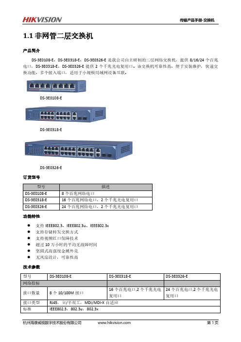
型号 DS-3E0108-E DS-3E0318-E DS-3E0326-E
描述 8 个百兆网络电口 16 个百兆网络电口,2 个千兆光电复用口 24 个百兆网络电口,2 个千兆光电复用口
功能特性
支持 IEEE802.3、IEEE802.3u、IEEE802.3x 支持存储转发交换方式 支持视频红口保障技术 超过 10 万小时的平均无故障时间 坚固式高强度金属外壳 无风扇设计,可靠性高
传输产品手册-交换机
1.1 非网管二层交换机
产品简介 DS-3E0108-E、DS-3E0318-E、DS-3E0326-E 是我公司自主研制的二层网络交换机,提供 8/16/24 个百兆
电口,DS-3E0318-E、DS-3E0326-E 提供 2 个千兆光电复用口。该交换机可靠性高、便于安装维护,快速交 换功能、多个接入端口,适用于小规模局域网设备互联。
1.6kg 335mm( 长)× 44.5mm( 高)× 176mm(深)
<12W
杭州海康威视数字技术股份有限公司
第2页
技术参数
型号 网络指标
接口数量
IL101 AI二路采集控制网关 使用说明书

IL101AI二路采集控制网关使用说明书2019.03注意事项与维护1、注意事项-请勿带电插拔核心板及外围模块!-请遵循所有标注在产品上的警示和指引信息。
-请保持本产品干燥。
如果不慎被任何液体泼溅或浸润,请立刻断电并充分晾干。
-使用中注意本产品的通风散热,避免温度过高造成元器件损坏。
-请勿在多尘、脏乱的环境中使用或存放本产品。
-请勿将本产品应用在冷热交替环境中,避免结露损坏元器件。
-请勿粗暴对待本产品,跌落、敲打或剧烈晃动都可能损坏线路及元器件。
-请勿使用有机溶剂或腐蚀性液体清洗本产品。
-请勿自行修理、拆卸本公司产品,如产品出现故障请及时联系本公司进行维修。
-擅自修改或使用未经授权的配件可能损坏本产品,由此造成的损坏将不予以保修。
2、售后维修如产品使用过程中出现硬件故障可根据售后服务政策进行维修;地址:广东省深圳市福田区天安数码城创新科技广场二期西座1905联系人:售后维修部电技术支持与定制1、技术支持范围1.1本公司产品的软、硬件资源提供情况咨询;1.2本公司产品的软、硬件手册使用过程中遇到的问题;1.3本公司提供的OEM、ODM售后技术支持;1.4本公司产品的故障判断及售后维修服务。
2、技术支持方式3.1目录注意事项与维护 (2)1、注意事项 (2)2、售后维修 (2)技术支持与定制 (3)1、技术支持范围 (3)2、技术支持方式 (3)第一章整机简介 (1)第二章技术参数 (2)第三章接口说明 (3)第四章硬件参数 (5)第五章软件功能 (6)第六章外形尺寸 (7)第一章整机简介IL101控制单元基于ARM Cortex-A7架构,以NXP(原Freescale)i.MX6UltraLite处理器为核心,采用全工业级元器件,完全按照工业标准设计制造,具备完善的接口防护功能和电气隔离措施,可以在恶劣环境中长期稳定运行。
该产品特点如下:●采用NXP(原Freescale)i.MX6UltraLite处理器,高性能、低功耗、高可靠性●核心模块所有元器件达到工业级-40至85℃温度范围●CPU本身支持ISO7816协议,可直接与国家电网ESAM/PSAM模块通信●内置超级电容,断电后至少可维持系统正常运行15秒,确保交易信息不丢失●采用模块化设计,可迅速针对客户的个性化需求提供私人定制服务●4路DI、4路DO,2路485、2路CAN,均采用电气隔离和接口保护,安全可靠●可通过SD卡升级系统,无需拆卸外壳,简单方便●宽电压范围,可在9至15V范围内安全可靠运行,且内置超级电容,无惧电压波动●采用铝合金型材外壳,带耳体积仅147×103×42mm,体积小巧、外形美观、安装方便●全面的状态指示灯,令系统运行、网络通讯、接口连接……所有状况一目了然●通讯方式多样,板载百兆网口、蓝牙和Wi-Fi、4G(或GPRS)模块●标准DB9调试串口●标准SD卡插槽,支持SD、SDHC和SDXC卡,最大实测容量64G,方便扩充本地存储空间●标准3.5mm立体声耳机接口,内置话筒,亦可增设1W×2喇叭或3.5mm单声道话筒接口第二章技术参数第三章接口说明●上方偏左是4G/GPRS状态指示灯●8位3.81mm间距绿端子包含4个接口,从左到右分别为:RS-485-1、RS-485-2、CAN1、CAN2这些接口都是与CPU电气隔离的,每位端子的功能均由端子上方的字符标识出来。
监控改造预算

需货单位: 工程名称:监控系统升级改造 报价日期:
序号 1 产品名称 视讯数据采集卡 监控主机 2 3 5 6 7 摄像机 不锈钢立杆 电源 视频线 电源线 PVC管 8 辅材 国产 12V20A SYV75-5 RVV-2*0.75 海康威视DS-2CC112P 规格型号 海康威视DS-4008HC 数量 2 1 8 3 8 1200 1200 单位 台 台 只 根 只 米 米 批 批 500.00 单价(元) 860.00 3800.00 790.00 800.00 70.00 3.00 3.00 金额(元) 1720.00 3800.00 6320.00 2400.00 560.00 3600.00 3600.00 1500.00 500.00 品牌产地 海康 定制 海康 定制 定制 按实际算 按实际算 按实际算 定制
地面相关工程 路面开槽与恢复 线路相关工程 摄像机更换及安装 其它设备 存储设备相关 A B C D 安装调试费 税 金 工程总价 设备总价 C
4800.00 800.00
4800.00 800.00
以实际工程量为准 以实际工程量为准
29600.00 A×16% (A+B)×0.05 A+B+C 4736.00 1716.80 36052.80
以上相关报价为预算价,竣工后及追加工程应以实际工程量为准。(有标注)
报价单位:铭硕科技
报价单位(公章)签字:
Hale Waihona Puke 地址:
48口千兆交换机参数

序号 1 2 3 4 5 6 7 8 9 10 11 12 13 14 15 16 功能及技术指标 ★交换容量≥250Gbps ★转发性能≥80Mpps ★固化10/100/1000M以太网端口≥48,千兆SFP光接口≥4个,同时可用 千兆口≥52 ★配置及日志存储等简化维护和管理,USB端口≥1个 支持链路协测功能,可快速检测链路的通断和光纤链路的单向性 ,并 支持端口下的环路检测功能,防止端口下因私接Hub 等设备形成的环路 而导致网络故障的现象 ★支持流镜像功能 ★支持IPv4和IPv6的三层路由功能 支持IPv4组播、IPv6组播,防止虚假应标,保留测试权利 支持DHCP Client、DHCP Relay、DHCP Snooping、DHCP Snooping ★支持IPv4 ACL,配置支持源/目的IPv6地址、源/目的端口的硬件IPv6 ACL,ACL80 支 持 Private VLAN , protocol based VLAN , Guest VLAN , Share vlan,Voice Vlan ★支持抗攻击,支持CPU限速功能,能限制非法报文对CPU的攻击,保护 交换机工作的稳定性 ★所投设备能检测到攻击源,并将攻击源隔离,保护交换机工作的稳定 ★支持 Web 认证功能,并和 802.1X 、 IPv4/IPv6 ACL 同时开启,防 ARP 欺 骗,CPU保护功能同时开启,不会相互冲突、制约 ★要求所投设备具备良好的扩展性,要求所投设备支持堆叠且单向堆叠 带宽≥2.5G ★支持ARP防欺骗的功能,在交换机端口启用802.1X和WEB认证功能的前 提下,能够禁止非法用户的ARP欺骗报文,保护合法用户免受其害,防 止合法用户的数据被窃取。提供工信部(原信息产业部)测试报告复印 备注
- 1、下载文档前请自行甄别文档内容的完整性,平台不提供额外的编辑、内容补充、找答案等附加服务。
- 2、"仅部分预览"的文档,不可在线预览部分如存在完整性等问题,可反馈申请退款(可完整预览的文档不适用该条件!)。
- 3、如文档侵犯您的权益,请联系客服反馈,我们会尽快为您处理(人工客服工作时间:9:00-18:30)。
IP101 LFPreliminary Data SheetSingle port 10/100 Fast Ethernet TransceiverFeatures10/100Mbps TX Full-duplex or half-duplex Supports Auto MDI/MDIX function Fully compliant with IEEE 802.3/802.3u Supports IEEE 802.3u auto-negotiation Supports MII interface IEEE 802.3 full duplex control specification Supports Automatic Power Saving mode Supports BaseLine Wander (BLW) compensation Supports Interrupt function Supports repeater mode Single 3.3V power supply with built-in 2.5V regulator DSP-based PHY Transceiver technology Flexible LED display for speed, duplex, link, activity and collision Supports flow control to communicate with other MAC through MDC and MDIO 0.25u, CMOS technology 48-pin LQFP Support Lead Free package (Please refer to the Order Information)General DescriptionIP101 LF is an IEEE 802.3/802.3u compliant single-port Fast Ethernet Transceiver for both 100Mbps and 10Mbps operations. It supports Auto MDI/MDIX function to simplify the network installation and reduce the system maintenance cost. To improve the system performance, IP101 LF provides a hardware interrupt pin to indicate the link, speed and duplex status change. IP101 LF provides Media Independent Interface (MII) to connect with different types of 10/100Mb Media Access Controller (MAC). IP101 LF is designed to use category 5 unshielded twisted-pair cable connecting to other LAN devices. IP101 LF Transceiver is fabricated with advanced CMOS technology, which the chip only requires 3.3V as power supply and consumes very low power in the Auto Power Saving mode. IP101 LF can be implemented as Network Interface Adapter with RJ-45 for twisted-pair connection. It can also be easily implemented into HUB, Switch, Router, Access Point.1/33 Copyright © 2004, IC Plus Corp.July 04, 2005 IP101 LF-DS-R08IP101 LFPreliminary Data SheetRevision HistoryRevision # IP101 LF-DS-R01 IP101 LF-DS-R02 IP101 LF-DS-R03 IP101 LF-DS-R04 IP101 LF-DS-R05 Initial release. Change DescriptionRemove RMII, SNI function. Add digital loopback requirement. Add reset timing description to Pin 42 RESET_N in page 9 Add input voltage swing limit to pin46 X1 and corresponding application circuit. Please refer to page 9, 27 and 29 IP101 LF-DS-R06 Add Crystal Specification and MII Timing. IP101 LF-DS-R07 Add the order information for lead free package. IP101 LF-DS-R08 Revise the general description & modify the application diagram.2/33 Copyright © 2004, IC Plus Corp.July 04, 2005 IP101 LF-DS-R08IP101 LFPreliminary Data SheetTransmit and Receive Data Path Block DiagramTXD100M bpsRXDM II In te rfa c e100M bps 10M bps4 B /5 B E ncoder10M bps4 B /5 B D ecoderS e r ia l t o P a r a lle lM I I R e g is t e r s100M bps 10M bpsD e s c r a m b le r S c r a m b le r100M bpsM a c h e s te r/N RZ D ecoder5B100M bpsM uxA u to N e g o t ia t io nS e r ia l t o P a r a lle l5B10M bps100M bpsC lo c k R e c o v e ry100M bps10M bpsC lo c k R e c o v e ryP a r a lle l t o S e r ia l P a r a lle l t o S e r ia l100M bps100M bps10M bpsM L T 3 /N R Z I D ecoder100M bpsS q u e lc hN R Z I/M L T -3 E ncoder10M bpsN R Z /M a n c h e s t er E ncoder100M bps 10M bpsD S P E n g in e100M bps10M bpsD / A & L in e D r iv e rTXOR J -4 5 C o n n e c to rRXIFigure 1: Flow chart of IP101 LF3/33 Copyright © 2004, IC Plus Corp.July 04, 2005 IP101 LF-DS-R08IP101 LFPreliminary Data SheetPin Assignments27. TEST_ON32. REGOUT36. AVDD3330. MDI_RN31. MDI_RP33. MDI_TN34. MDI_TP28. RTSET35. AGND29. AGND26. MDIO25. MDC37. AN_ENA 38. DPLX 39. SPD 40. RPTR 41. APS 42. RESET_N 43. ISOL 44. NC 45. DGND 46. X1 47. X2 48. INTR24. RX_ER 23. CRS /LEDMOD 22. RX_DV 21. RXD0 20. RXD1IP101 LFFast Ethernet Single Phy Transceiver Chip 48 pins LQFP package19. RXD2 18. RXD3 17. DGND 16. RX_CLK 15. LED4/ PHYAD4 14. DVDD33 13. LED3/ PHYAD310. LED1/ PHYAD1Figure 2 : IP101 LF pins assignment4/33 Copyright © 2004, IC Plus Corp.12. LED2/ PHYAD29. LED0/ PHYAD07. TX_CLK11. DGND2. TX_EN8. REGIN3. TXD34. TXD25. TXD16. TXD01. COLJuly 04, 2005 IP101 LF-DS-R08IP101 LFPreliminary Data Sheet1 Pin DescriptionsType LI I/O I O Pin no. Description Latched Input in power up or reset Bi-directional input and output Input Output Label Type Type PD PU P OD Description Internal Pull-Down Internal Pull-Up Power Open Drain DescriptionMII and PCS Interface - Management Interface Pins 25 MDC I Management Data Interface Clock: This pin provides a clock reference to MDIO. The clock rate can be up to 10MHz. 26 MDIO I/O Management Data interface Input/Output: The function of this pin is to transfer management information between PHY and MAC.MII and PCS Interface – Media Independent Interface (MII) Pins 2 TX_EN I Transmit Enable: This pin is an active high input. At high status, (PD) it indicates the nibble data in TXD[3:0] is valid. 7 TX_CLK O Transmit Clock: This pin provides a continuous 25MHz clock at 100BT and 2.5Mbps at 10BT as timing reference for TXD[3:0] and TX_EN when the chip operates under MII. Transmit Data: When TX_EN is set high, MAC will transmit data through these 4 lines to PHY which the transmission is synchronizing with TX_CLK. Receive Data Valid: At high status stands for data flow is present within RXD[0:3] lines and low means no data exchange occurred. Receive Clock: This pin provides 25MHz for 100BT or 2.5Mhz for 10BT and RX_DV pin uses this pin as its reference under MII. Receive Data: These 4 data lines are transmission path for PHY to send data to MAC and they are synchronizing with RX_CLK.3, 4, 5, 6TXD[3:0]I22RX_DVO16 18, 19, 20, 21RX_CLK RXD[3:0]O O5/33 Copyright © 2004, IC Plus Corp.July 04, 2005 IP101 LF-DS-R08IP101 LFPreliminary Data SheetPin Descriptions (continued)Pin no. Label Type Description MII and PCS Interface – Media Independent Interface (MII) Pins 24 RX_ER O Receive error: This pin outputs a high status when errors (PD) occurred in the decoded data in the reception. (Notice: This pin is pulled down internally) 1 COL O/LI (PD) O (PD) Collision Detected: When this pin outputs a high status signal it means collision is detected. (Notice: This pin is pulled down internally) Carrier Sense: When signal output from this pin is high indicates the transmission or reception is in process and at low status means the line is in idle state. LEDMOD: During power on reset, this pin status is latched to determine at which LED mode to operate, please refer to the LED pins description. (Notice: This pin is pulled down internally)23CRS/LEDMOD6/33 Copyright © 2004, IC Plus Corp.July 04, 2005 IP101 LF-DS-R08IP101 LFPreliminary Data SheetPin Descriptions (continued)Pin no. Label Type Description Transmit Output Pair: Differential pair shared by 100Base-TX, and 10Base-T modes. When configured as 100Base-TX, output is an MLT-3 encoded waveform. When configured as 10Base-TX, the output is Manchester code. Receive Input Pair: Differential pair shared by 100Base-TX, and 10Base-T modes. Set high to this pin will isolate IP101 LF from other MAC. This action will also isolate the MDC/MDIO management interface. The power usage is at minimum when this pin is activated. This pin can be directly connected to GND or VCC. (An internal weak pulled-down is used to be inactive as a default) Enable this pin to high will put the IP101 LF into repeater mode. This pin can be directly connected to GND or VCC. (An internal weak pulled-down is used to be inactive as a default) This pin is latched to input during a power on or reset condition. Set high to put the IP101 LF into 100Mbps operation. This pin can be directly connected to GND or VCC. (An internal weak pulled-up is used to set 100Mbps as a default) This pin is latched to input during a power on or reset condition. Set high to enable full duplex. This pin can be directly connected to GND or VCC. (An internal weak pulled-up is used to set full duplex as a default) This pin is latched to input during a power on or reset condition. Set high to enable auto-negotiation mode, set low to force mode. This pin can be directly connected to GND or VCC. (An internal weak pulled-up is used to enable N-WAY as a default) Set high to put the IP101 LF into APS mode. This pin can be directly connected to GND or VCC. Refer to Section 7 for more information. (An internal weak pulled-up is used to enable APS mode as a default) This pin should be left open or pull up (Internal pull up.) Cable Transmission Interface 34 MDI_TP I/O 33 MDI_TN I/O31 30MDI_RP MDI_RNI/O I/O I (PD)IC Configuration Options 43 ISOL40RPTRI (PD) LI/O (PU)39SPD38DPLXLI/O (PU)37AN_ENALI/O (PU)41APSI (PU)44NC(PU)7/33 Copyright © 2004, IC Plus Corp.July 04, 2005 IP101 LF-DS-R08IP101 LFPreliminary Data SheetPin Descriptions (continued)Pin no. Label Type Description LED and PHY Address Configuration These five pins are latched into the IP101 LF during power up reset to configure PHY address [4:0] used for MII management register interface. And then, in normal operation after initial reset, they are used as driving pins for status indication LED. The driving polarity, active low or active high, is determined by each latched status of the PHY address [4:0] during power-up reset. If latched status is high then it will be active low, and if latched status is Low then it will be active high. Moreover, IP101 LF provides 2 LED operation modes. If 2nd LED mode is selected by pulling up pin CRS, only 3 LEDs are needed for status indication. Default is first LED mode. LED mode 1 LINK FULL DUPLEX 10BT /ACT(blinking) 100BT /ACT(blinking) COL LI/O LED mode 2 LINK /ACT(blinking) FULL DUPLEX /COL(blinking) 10BT 100BT ReservedLED0 LED1 LED2 LED3 LED4 9 PHYAD0/ LED0PHY Address [0] Status: Mode1: Active when linked. Mode2: Active when linked and blinking when transmitting or receiving data. PHY Address [1] Status: Mode1: Active when in Full Duplex operation. Mode2: Active when in Full Duplex operation and blinking when collisions occur. PHY Address [2] Status: Mode1: Active when linked in 10Base-T mode, and blinking when transmitting or receiving data. Mode2: Active when linked in 10Base-T mode. PHY Address [3] Status: Mode1: Active when linked in 100Base-TX and blinking when transmitting or receiving data. Mode2: Active when linked in 100Base-TX mode. PHY Address [4] Status: Mode1: Active when collisions occur. Mode2: Reserved.10PHYAD1/ LED1LI/O12PHYAD2/ LED2LI/O13PHYAD3/ LED3LI/O15PHYAD4/ LED4LI/O8/33 Copyright © 2004, IC Plus Corp.July 04, 2005 IP101 LF-DS-R08IP101 LFPreliminary Data SheetPin Descriptions (continued)Pin no. Label Type Description Clock and Miscellaneous - Crystal Input/Output Pins 47 X2 O 25MHz Crystal Output: Connects to crystal to provide the 25MHz output. It must be left open when X1 is driven with an external 25MHz oscillator or set to low with a pull down resistor. 46 X1 I 25MHz Crystal Input: Connects to crystal to provide the 25MHz crystal input. If a 25MHz oscillator is used, connect X1 to the oscillator output. The input voltage of this pin should not exceed 2.75v. A voltage divider formed by 2 resistors is recommended if the output voltage of oscillator is over 2.75v. Please refer to the application circuit in page 27 and 29Clock and Miscellaneous - Miscellaneous Pins 42 RESET_N I RESET_N: Enable a low status signal will reset the chip. For a complete reset function. 25MHz clock (x1) must be active for a minimum of 10 clock cycles before the rising edge of RESET_N. Chip will be able to operate after 2.5ms delay of the rising edge of RESET_N. The 2.5ms extention is to ensure the stability of system power. INTR 48 O Interrupt Pin: When the MII register 17:<15> is set to high, this (OD) pin is used as an interrupt pin (Notice: this is an open drain output, so an external pulled-up resistor is needed) 27 TEST_ON (PD) Test Enable: Set this pin to high to enable test mode, while for normal operation, this pin does not need to be connected. (An internal weak pulled-down is used to disable test mode as a default) Transmit Bias Resistor Connection: This pin should be connected to GND via a 6.2KΩ (1%) resistor to define driving current for transmit DAC.28ISETI9/33 Copyright © 2004, IC Plus Corp.July 04, 2005 IP101 LF-DS-R08IP101 LFPreliminary Data SheetPin Descriptions (continued)Pin no. Label Type P P P P P P Description Regulator Power Output: This is a regulator power output for IP101 LF digital circuitry. 3.3V Analog power input: This is a 3.3V power supply for analog circuitry, and it should be decoupled carefully. Analog Ground: These 2 pins should connect to motherboard’s GND. Regulator Power Input: This is a regulator power input from Pin32. No external regulator needed. 3.3V Digital Power input: This is a 3.3V power supply for digital circuitry. Digital Ground: These 3 pins should connect to motherboard’s GND. Power and Ground 32 REGOUT 36 29,35 8 14 11,17,45 AVDD33 AGND REGIN DVDD33 DGND10/33 Copyright © 2004, IC Plus Corp.July 04, 2005 IP101 LF-DS-R082 Register Descriptions Bit BitNameDescription/UsageDefault value(h): 3100Register 0 : MII Control Register15 ResetWhen set, this action will bring both status and control registers of the PHY to default state. This bit is self-clearing. 1 = Software reset 0 = Normal operation0, RW 14 Loop-back This bit enables loop-back of transmit data to the receive data path, i.e., TXD to RXD. IP101 LF requires at least 512us to link after programming this bit. TX/RX packets should be activated after 512us. 1 = enable loop-back 0 = normal operation0, RW13 Speed Selection This bit sets the speed of transmission. 1 = 100Mbps 0 = 10Mbps1, RW12 Auto-Negotiation Enable This bit determines the auto-negotiation function. 1 = enable auto-negotiation; bits 13 and 8 will be ignored. 0 = disable auto-negotiation; bits 13 and 0:<8> will determine the link speed and the data transfer mode, under this condition.Auto-MDIX function should be disabled (set Reg16.11=1) if this bit has been set to “0”. Please refer to section 7 Auto-MDIX function description for details.1, RW (TP)11 Power Down This bit will turn down the power of the PHY chip and the internal crystal oscillator circuit if this bit is enabled. The MDC and MDIO are still activated for accessing to the MAC. 1 = power down0 = normal operation0, RW10 Isolate 1=electrically Isolate PHY from MII but not isolate MDC and MDIO0=normal operation0,RW9 Restart Auto- Negotiation This bit allows the Nway auto-negotiation function to be reset. 1 = restart auto-negotiation0 = normal operation0, RW8 Duplex Mode This bit sets the duplex mode if auto-negotiation is disabled (bit 12=0) 1 = full duplex 0 = half duplexAfter completing auto-negotiation, this bit will reflect the duplex status.(1: Full duplex, 0: Half duplex)1, RW7 Collision T est 1=enable COL signal test 0=disable COL signal test0,RW6:0 Reserved 0, RORegister Descriptions (continued)BitNameDescription/UsageDefault value (h): 7849Register 1 : MII Status Register15 100Base-T4 1 = enable 100Base-T4 support0 = suppress 100Base-T4 support0, RO 14 100Base-TX Full Duplex 1 = enable 100Base-TX full duplex support0 = suppress 100Base-TX full duplex support1, RO 13 100BASE-TX Half Duplex 1 = enable 100Base-TX half duplex support0 = suppress 100Base-TX half duplex support 1, RO 12 10Base-T Full Duplex 1 = enable 10Base-T full duplex support 0 = suppress 10Base-T full duplex support1, RO 11 10_Base-T Half Duplex 1 = enable 10Base-T half duplex support0 = suppress 10Base-T half duplex support 1, RO 10:7 Reserved0, RO6 MF Preamble Suppression The IP101 LF will accept management frames with preamble suppressed. The IP101 LF acceptsmanagement frames without preamble. A Minimum of 32 preamble bits are required for the first SMI read/write transaction after reset. One idle bit is required between any two management transactions as per IEEE802.3u specifications1, RO 5 Auto- Negotiation Complete 1 = auto-negotiation process completed 0 = auto-negotiation process not completed 0, RO4 Remote Fault 1 = remote fault condition detected (cleared on read) 0 = no remote fault condition detected 0, RO/LH3 Auto-Negotiation 1 = Link had not been experienced fail state0 = Link had been experienced fail state 1, RO 2 Link Status 1 = valid link established 0 = no valid link established 0, RO/LL 1Jabber Detect1 = jabber condition detected 0 = no jabber condition detected 0, RO/LH 0 ExtendedCapability 1 = extended register capability 0 = basic register capability only1, RORegister Descriptions (continued)Bit Name Description/Usage Default value (h): 0243Register 2 : PHY Identifier Register 115:0 PHYID1 PHY identifier ID for software recognize IP101 LF 0X0243, ROBit Name Description/Usage Default value (h): 0C54Register 3 : PHY Identifier Register 215:0 PHYID2 PHY identifier ID for software recognize 0X0C54, RO Note : Register 2 and register 3 identifier registers altogether consist of Vender model, model revision number and Organizationally Unique identifier (OUI) information. Total of 32 bits allocate in these 2 registers and they can return all zeroes in all bits if desired. Register 2 contains OUI’s most significant bits and OUI’s lest significant bits, Vender model, Model revision number are allocated in register 3.Register Descriptions (continued)Register 4 lists the advertised abilities during auto-negotiation for what will be transmitted to IP101 LF’s Link Partner.Bit Name Description/Usage Default value (h): 0001Register 4 : Auto-Negotiation Advertisement Register15 NP Next Page bit.0 = transmitting the primary capability data page1 = transmitting the protocol specific data page0, RO14 Reserved 0,RO 13 RF 1 = advertise remote fault detection capability0 = do not advertise remote fault detection capabilitySoftware reset(reg0.15) will not set this bit to default valueif this bit has been programmed to “1”. Hardware reset orpower on reset will set it to default value.0, RW12 Reserved 0,RW11 Asymmetric.Pause 1 = asymmetric flow control is supported by local node0 = asymmetric flow control is NOT supported by localnodeSoftware reset(reg0.15) will not set this bit to default valueif this bit has been programmed to “1”. Hardware reset orpower on reset will set it to default value.0, RW10 Pause 1 = flow control is supported by local node0 = flow control is NOT supported by local nodeSoftware reset(reg0.15) will not set this bit to default valueif this bit has been programmed to “1”. Hardware reset orpower on reset will set it to default value.0, RW9 T4 1 = 100Base-T4 is supported by local node0 = 100Base-T4 not supported by local nodeSoftware reset(reg0.15) will not set this bit to default valueif this bit has been programmed to “0”. Hardware reset orpower on reset will set it to default value.0, RO8 TX Full Duplex 1 = 100Base-TX full duplex is supported by local node0 = 100Base-TX full duplex not supported by local nodeSoftware reset(reg0.15) will not set this bit to default valueif this bit has been programmed to “0”. Hardware reset orpower on reset will set it to default value.1, RW7 TX 1 = 100Base-TX is supported by local node0 = 100Base-TX not supported by local nodeSoftware reset(reg0.15) will not set this bit to default valueif this bit has been programmed to “0”. Hardware reset orpower on reset will set it to default value.1, RW6 10 Full Duplex 1 = 10Base-T full duplex supported by local node0 = 10Base-T full duplex not supported by local nodeSoftware reset(reg0.15) will not set this bit to default valueif this bit has been programmed to “0”. Hardware reset orpower on reset will set it to default value.1, RWRegister Descriptions (continued)Bit Name Description/Usage Default value (h): 0001Register 4 : Auto-Negotiation Advertisement Register (continued)5 10 1 = 10Base-T is supported by local node0 = 10Base-T not supported by local nodeSoftware reset(reg0.15) will not set this bit to default valueif this bit has been programmed to “0”. Hardware reset orpower on reset will set it to default value.1, RW4:0 Selector Binary encoded selector supported by this node. Currentlyonly CSMA/CD <00001> is specified. No other protocolsare supported. <00001>,RORegister Descriptions (continued)Register 5 describes the advertised abilities of the Link Partner’s PHY when it is receiving data during the process of auto-negotiation. If next-pages are supported, this register may change after the auto-negotiation has established.Bit Name Description/Usage Default value (h): 0080Register 5 : Auto-Negotiation Link Partner Ability Register15 Next Page Next Page bit.0 = transmitting the primary capability data page1 = transmitting the protocol specific data page0, RO14 Acknowledge 1 = link partner acknowledges reception of local node’scapability data word0 = no acknowledgement0, RO13 Remote Fault 1 = link partner is indicating a remote fault0 = link partner does not indicate a remote fault0, RO12 Reserved 0,RO11 Asymmetric.Pause 1 = asymmetric flow control is supported by local node0 = asymmetric flow control is NOT supported by localnode0, RO10 Pause 1 = flow control is supported by Link partner0 = flow control is NOT supported by Link partner0, RO9 T4 1 = 100Base-T4 is supported by link partner0 = 100Base-T4 not supported by link partner0, RO8 TXFD 1 = 100Base-TX full duplex is supported by link partner0 = 100Base-TX full duplex not supported by link partner0, RO7 100BASE-TX 1 = 100Base-TX is supported by link partner0 = 100Base-TX not supported by link partnerThis bit will also be set after the link in 100Base isestablished by parallel detection.0, RO6 10FD 1 = 10Base-T full duplex is supported by link partner0 = 10Base-T full duplex not supported by link partner0, RO5 10Base-T 1 = 10Base-T is supported by link partner0 = 10Base-T not supported by link partnerThis bit will also be set after the link in 10Base isestablished by parallel detection.0, RO4:0 Selector Link Partner’s binary encoded node selector Currently onlyCSMA/CD <00001> is specified <00000>,RORegister Descriptions (continued)Register 6 defines more auto-negotiation registers to meet the requirement.Bit Name Description/Usage Default value(h):0000Register 6 : Auto-Negotiation Expansion Register15:5 Reserved This bit is always set to 0. 0, RO4 MLF This status indicates if a multiple link fault has occurred.1 = fault occurred0 = no fault occurred0, RO3 LP_NP_ABLE This status indicates if the link partner supports Next Pagenegotiation.1 = supported0 = not supported0, RO2 NP_ABLE This bit indicates if the device is able to send additional NextPages.0, RO1 PAGE_RX This bit will be set if a new link code word page has beenreceived. It is cleared automatically after theauto-negotiation link partner’s ability register (register 5) isread by the management.0, RO0 LP_NW_ABLE 1 = link partner supports Nway auto-negotiation. 0, RORegister Descriptions (continued)Register 16 and register 17 are defined by IC Plus Corp. and some of them are for internal testing purpose.Bit Name Description/Usage Default value (h): 0000Register 16 : PHY Spec. Control Register15 Debug Mode 0 = IP101 LF operates at normal mode1 = IP101 LF operates at debug mode, for internal useonly(Notice the functionalities of bit 16:<14>, 16:<13>,16:<12>, and 16:<4:0> depend on the setting of this bit16:<15>Software reset(reg0.15) will not set this bit to default valueif this bit has been programmed to “1”. Hardware reset orpower on reset will set it to default value.0, R/W 14:12 Reserved 0,RO 11 Auto MDIX Off Set high to disable the automatic switch of MDI and MDI-Xmodes. If AN is disabled by setting pin37=0 during powerup, this bit will be set to 1 (Auto-MDIX off) automatically.Setting Reg0.12=1 will re-activate AN, in this case, if userneeds Auto-MDIX function, this bit should be set to 0. Fordetails, please refer to section 7 Auto-MDIX functiondescription.0, R/W10 HeartBeatEnable Heart beat function enable at 10Base-TSoftware reset(reg0.15) will not set this bit to default valueif this bit has been programmed to “1”. Hardware reset orpower on reset will set it to default value.0, R/W9 JabberEnable Jabber function enable at 10Base-TSoftware reset(reg0.15) will not set this bit to default valueif this bit has been programmed to “1”. Hardware reset orpower on reset will set it to default value.0, R/W8 Far-EndFault Enable/Disable To enable or disable the functionality of Far-End FaultMode Enable Disable100Base-TX 1 0Software reset(reg0.15) will not set this bit to default valueif this bit has been programmed to “1”. Hardware reset orpower on reset will set it to default value.0, R/W7 AnalogPowerSaving Disable Set high to disable the power saving duringauto-negotiationSoftware reset(reg0.15) will not set this bit to default valueif this bit has been programmed to “1”. Hardware reset orpower on reset will set it to default value.0, R/W6 Reserved 0,RO5 BypassDSPreset Set high to bypass the reset DSP mechanism in PCSsub-layerSoftware reset(reg0.15) will not set this bit to default valueif this bit has been programmed to “1”. Hardware reset orpower on reset will set it to default value.0, R/W4:3 Reserved 0,RORegister Descriptions (continued)Bit Name Description/Usage Default value (h): 0000Register 16 : PHY Spec. Control Register (continued)2 Repeater Mode Set high to put IP101 LF into repeater modeSoftware reset(reg0.15) will not set this bit to default valueif this bit has been programmed to “1”. Hardware reset orpower on reset will set it to default value.0, R/W1 APS Mode Set high to enable Auto Power Saving modeSoftware reset(reg0.15) will not set this bit to default valueif this bit has been programmed to “1”. Hardware reset orpower on reset will set it to default value.0, R/W0 Analog Off Set high to power down analog transceiverSoftware reset(reg0.15) will not set this bit to default valueif this bit has been programmed to “1”. Hardware reset orpower on reset will set it to default value.0, R/WRegister Descriptions (continued)Bit Name Description/Usage Default value (h): 0E00Register 17 : PHY Interrupt Ctrl/Status Register15 INTR pin used Set high to enable pin48 as an interrupt pin. Pin48 will behigh impedance if this bit is set low.0, R/W14:12 Reserved 0,RO 11 All Mask When this bit is set high, changes in all events will notcause an interrupt1, R/W10 Speed Mask When this bit is set high, changes in speed mode will notcause an interrupt1, R/W9 Duplex Mask When this bit is set high, changes in duplex mode will notcause an interrupt1, R/W8 Link Mask When this bit is set high, changes in link status will notcause an interrupt1, R/W7 ArbiterStateEnable When this bit is set low, changes in N-WAY arbiter statemachine will not cause an interrupt0, R/W6 ArbiterStateChangeFlag to indicate N-WAY arbiter change interrupt 0, RC 5:3 Reserved 0,RO 2 LinkStatusChangeFlag to indicate link status change interrupt 0, RC1 Speed Change Flag to indicate speed change interrupt 0, RC0 Duplex Change Flag to indicate duplex change interrupt 0, RC。