SN-T5-2,SNT5-2-BRASS, 规格书,Datasheet 资料
Atlas Sound Strategy Series 扬声器系统说明书
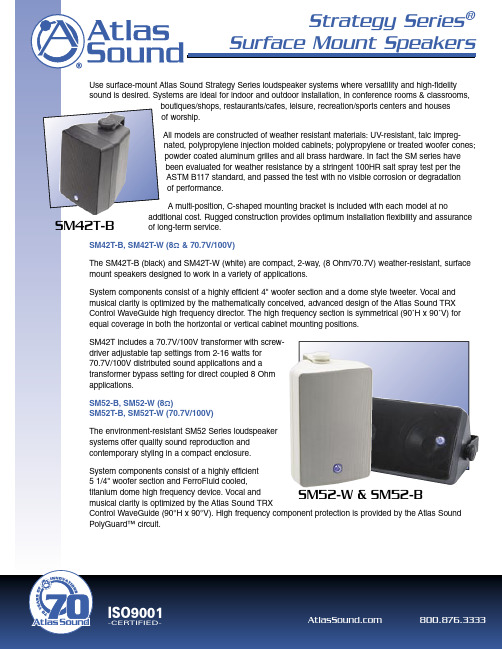
SM42T includes a 70.7V/100V transformer with screwdriver adjustable tap settings from 2-16 watts for 70.7V/100V distributed sound applications and a transformer bypass setting for direct coupled 8 Ohm applications.
SM Series Common Features • Compact, 2-way loudspeaker systems for
exceptional performance in music and sound reinforcement systems • Weather-resistant construction for year-round indoor or outdoor use • UV-resistant-talc-impregnated-polypropylene injection molded enclosures • Powder coated aluminum grilles • Conform to 100HR salt spray test per ASTM B117 • Color matched heavy-duty zinc chromate plated and powder coated “C” Style mounting bracket included • Atlas Sound TRX WAVEGUIDE™– A constant directivity style high frequency wave guide system provides accurate, even high frequency coverage • Sealed input cover to prevent connector corrosion • All SAE brass hardware inserts allow easy integration of “off-the-shelf” security hardware • OMNIMOUNT™ compatible • 70V & 8-Ohm
514中文说明书
. /_
/_ μ 8 ܖ
ˏ ၠූ
-
ၠ
-
p
p ඪ/_
-) )
d,- $ (-e
ඪ /_ ऋķś
ݖķś Ĝ×-
)- /_ " " " " O %%. ቱූ ´t) ቱූ #/ ݖ Oቱූ Ĝ×-
操作前的准备
基本接线图
①、推荐“0V/公共端”接地,若一个系统中有多台调速器,请将所有的”0V/公共端”连接在一起 一点接地. ②、当调速器使用电流控制时,端子 14 和 15 需要短接作为堵转过载信号。
ȩ
Ĝ
ҧ 2 // s Ƒؽ
!! !! !! ' !! ' !! !! 8 h !! ࢠ֧ Ѥ !! ๛ ඥ Ѥ V (! $)* + Ѥ !! ๛ ඥ Ѥ V (! $)* + Ѥ !! ๛ ඥ Ѥ V (! $)* + , Ѥ V (! $)* + , Ѥ V (! $)* + !! ' !! '
జnj
Ȓ̵O
ඥ ffffffffffffffffffffffff ඥ ffffffffffffffffffff Ѥ-fffffffffffffffffffffffff Ѥᇍfffffffffffffffffff -˫fffffffffffffffffffffffff ঠѤfffffffffffffffffffffffff ͵ Ѥfffffffffffffffffffffffff ᇏW8 Ѥfffffffffffffffffffffff njᇕ fffffffffffffffffffffffff < ͩ$ ᇍfffffffffffffffffff
SN75452BD中文资料
元器件交易网IMPORTANT NOTICETexas Instruments and its subsidiaries (TI) reserve the right to make changes to their products or to discontinueany product or service without notice, and advise customers to obtain the latest version of relevant informationto verify, before placing orders, that information being relied on is current and complete. All products are soldsubject to the terms and conditions of sale supplied at the time of order acknowledgement, including thosepertaining to warranty, patent infringement, and limitation of liability.TI warrants performance of its semiconductor products to the specifications applicable at the time of sale inaccordance with TI’s standard warranty. Testing and other quality control techniques are utilized to the extentTI deems necessary to support this warranty. Specific testing of all parameters of each device is not necessarilyperformed, except those mandated by government requirements.CERTAIN APPLICATIONS USING SEMICONDUCTOR PRODUCTS MAY INVOLVE POTENTIAL RISKS OFDEATH, PERSONAL INJURY, OR SEVERE PROPERTY OR ENVIRONMENTAL DAMAGE (“CRITICALAPPLICATIONS”). TI SEMICONDUCTOR PRODUCTS ARE NOT DESIGNED, AUTHORIZED, ORWARRANTED TO BE SUITABLE FOR USE IN LIFE-SUPPORT DEVICES OR SYSTEMS OR OTHERCRITICAL APPLICATIONS. INCLUSION OF TI PRODUCTS IN SUCH APPLICATIONS IS UNDERSTOOD TOBE FULLY AT THE CUSTOMER’S RISK.In order to minimize risks associated with the customer’s applications, adequate design and operatingsafeguards must be provided by the customer to minimize inherent or procedural hazards.TI assumes no liability for applications assistance or customer product design. TI does not warrant or representthat any license, either express or implied, is granted under any patent right, copyright, mask work right, or otherintellectual property right of TI covering or relating to any combination, machine, or process in which suchsemiconductor products or services might be or are used. TI’s publication of information regarding any thirdparty’s products or services does not constitute TI’s approval, warranty or endorsement thereof.Copyright © 1999, Texas Instruments Incorporated。
SI2302-TP;中文规格书,Datasheet资料

Revision: A
/
3 of 5
2011/01/01
VGS, Gate to Source Voltage (V) ID, Drain Current (A)
VTH, Normalized Gate-Source Threshold Voltage
RDS(ON), Normalized RDS(ON), On-Resistance(Ohms)
IS, Source-drain current (A)
ID, Drain Current (A)
SI2302
10 25 C
Maximum Ratings @ 25OC Unless Otherwise Specified
Symbol VDS ID IDM VGS
PD R©JA
TJ
TSTG
Parameter Drain-source Voltage Drain Current-Continuous Drain Current-Pulsed a Gate-source Voltage
MCC
TM
Micro Commercial Components
5 VDS=10V ID=3.6A
4
3
2
1
0
0
2
4
6
Qg, Total Gate Charge (nC)
Figure 7. Gate Charge
VDD
RL VIN
D
VOUT
VGS
RGEN G
S
Figure 9. Switching Test Circuit
TruStability标准精度硅陶瓷(SSC)系列压力传感器说明说明书

DESCRIPTIONThe TruStability ® Standard Accuracy Silicon Ceramic (SSC) Series is a piezoresistive silicon pressure sensor offering a ratiometric analog output for reading pressure over the specified full scale pressure span and temperature range.The SSC Series is fully calibrated and temperaturecompensated for sensor offset, sensitivity, temperature effects, and non-linearity using an on-board Application SpecificIntegrated Circuit (ASIC). Calibrated output values for pressure are updated at approximately 1 kHz.The SSC Series is calibrated over the temperature range of -20 C to 85 C [-4 F to 185 F]. The sensor is characterized for operation from a single power supply of either 3.3 Vdc or 5.0 Vdc.These sensors measure absolute, differential, and gage pressures. The absolute versions have an internal vacuum reference and an output value proportional to absolutepressure. Differential versions allow application of pressure to either side of the sensing diaphragm. Gage versions are referenced to atmospheric pressure and provide an output proportional to pressure variations from atmosphere.The TruStability ®pressure sensors are intended for use with non-corrosive, non-ionic gases, such as air and other dry gases. An available option extends the performance of these sensors to non-corrosive, non-ionic liquids.All products are designed and manufactured according to ISO 9001 standards.FEATURESIndustry-leading long-term stabilityExtremely tight accuracy of 0.25% FSS BFSL (Full ScaleSpan Best Fit Straight Line)Total error band of2% full scale span maximumModular and flexible design offers customers a variety of package styles and options, all with the same industry-leading performance specificationsMiniature 10 mm x 10 mm [0.39 in x 0.39 in] packageLow operating voltageExtremely low power consumptionRatiometric analog outputHigh resolution (min. 0.03 %FSS) Precision ASIC conditioning and temperature compensated over -20 C to 85 C [-4 F to 185F] temperature rangeRoHS compliantVirtually insensitive to mounting orientationInternal diagnostic functions increase system reliabilityAlso available with I 2C or SPI digital outputAbsolute, differential and gage typesPressure ranges from 1 psi to 150 psi (60 mbar to 10 bar)Custom calibration availableVarious pressure port options Liquid media option2 /sensingPOTENTIAL APPLICATIONS Medical:- Airflow monitors- Anesthesia machines - Blood analysis machines - Gas chromatography - Gas flow instrumentation - Kidney dialysis machines - Oxygen concentrators - Pneumatic controls - Respiratory machines - Sleep apnea equipment - VentilatorsIndustrial:- Barometry- Flow calibrators- Gas chromatography - Gas flow instrumentation - HVAC- Life sciences- Pneumatic controls1Honeywell Sensing and Control 3101. Absolute maximum ratings are the extreme limits the device will withstand without damage.2. Ratiometricity of the sensor (the ability of the device to scale to the supply voltage) is achieved within the specified operating voltage for eachoption.3. The sensor is not reverse polarity protected. Incorrect application of supply voltage or ground to the wrong pin may cause electrical failure.4. The compensated temperature range is the temperature range over which the sensor will produce an output proportional to pressure withinthe specified performance limits.5. The operating temperature range is the temperature range over which the sensor will produce an output proportional to pressure but may notremain within the specified performance limits.6. Accuracy: The maximum deviation in output from a Best Fit Straight Line (BFSL) fitted to the output measured over the pressure range at25 °C [77 °F]. Includes all errors due to pressure non-linearity, pressure hysteresis, and non-repeatability.7. Total Error Band: The maximum deviation from the ideal transfer function over the entire compensated temperature and pressure range.Includes all errors due to offset, full scale span, pressure non-linearity, pressure hysteresis, repeatability, thermal effect on offset, thermal effect on span, and thermal hysteresis.8. Full Scale Span (FSS) is the algebraic difference between the output signal measured at the maximum (Pmax.) and minimum (Pmin.) limits ofthe pressure range. (See Figure 1 for ranges.)9. Life may vary depending on specific application in which sensor is utilized. 10. Contact Honeywell Customer Service for detailed material information.CAUTIONPRODUCT DAMAGEEnsure liquid media is applied to Port 1 only; Port 2 is not compatible with liquids.Ensure liquid media contains no particulates. All TruStability ®sensors are dead-ended devices. Particulates can accumulate inside the sensor, causing damage or affecting sensor output.Recommend that the sensor be positioned with Port 1 facing downwards; any particulates in the system are less likely to enter and settle within the pressure sensor if it is in this position.Ensure liquid media does not create a residue when dried; build-up inside the sensor may affect sensor output. Rinsing of a dead-ended sensor is difficult and has limited effectiveness for removing residue.Ensure liquid media are compatible with wetted materials. Non-compatible liquid media will degrade sensor performance and may lead to sensor failure.Failure to comply with these instructions may result in product damage.4 /sensing11. The transfer function limits define the output of the sensor at a given pressure input. By specifying Pmin. and Pmax., the output at Pmin. andPmax., the complete transfer function of the sensor is defined. See Figure 2 for a graphical representation of the transfer function. Other transfer functions are available. Contact Honeywell Customer Service for more information.12. Digital outputs (SPI or I 2C) are also available. Contact Honeywell Customer Service for more information. 13. Custom pressure ranges are available. Contact Honeywell Customer Service for more information. 14. See Table 5 for an explanation of sensor pressure types. 15. See CAUTION on previous page.Honeywell Sensing and Control 5SSCSANN100PGAA3 SIP package, AN pressure port, no diagnostics, 100Output is proportional to the difference between the pressures applied to each port. (Port 1 Port 2)50% point of transfer function set at Port 1 = Port 2.Long-term Stability (1000 hr, 25 C [77 F]) 0.25% FSS 0.25% FSS 0.25% FSS 0.25% FSS 0.25% FSS 0.35% FSS 0.35% FSS 0.25% FSS 0.25% FSS 0.25% FSS 0.35% FSS 0.35% FSS 0.25% FSS 0.25% FSS 0.25% FSS 0.25% FSS 0.25% FSS6 /sensingLong-term Stability (1000 hr, 25 C [77 F]) 0.25% FSS 0.25% FSS 0.25% FSS 0.25% FSS 0.25% FSS 0.25% FSS 0.35% FSS 0.35% FSS 0.35% FSS 0.35% FSS 0.35% FSS 0.25% FSS 0.25% FSS 0.25% FSS 0.25% FSS 0.25% FSS 0.35% FSS 0.35% FSS 0.35% FSS0.35% FSS 0.35% FSS0.35% FSS 0.25% FSS 0.25% FSS 0.25% FSS 0.25% FSS 0.25% FSS 0.25% FSS16. Overpressure: The maximum pressure which may safely be applied to the product for it to remain in specification once pressure is returned tothe operating pressure range. Exposure to higher pressures may cause permanent damage to the product. Unless otherwise specified this applies to all available pressure ports at any temperature with the operating temperature range.17. Burst pressure: The maximum pressure that may be applied to any port of the product without causing escape of pressure media. Productshould not be expected to function after exposure to any pressure beyond the burst pressure.18. Common mode pressure: The maximum pressure that can be applied simultaneously to both ports of a differential pressure sensor withoutcausing changes in specified performance.Honeywell Sensing and Control78 /sensingHoneywell Sensing and Control910 /sensingHoneywell Sensing and Control 11Sensing and Control Honeywell1985 Douglas Drive NorthGolden Valley, MN 55422 008215-2-EN IL50 GLO Printed in USA March 2011© 2011 Honeywell International Inc.WARNINGWARRANTY/REMEDYHoneywell warrants goods of its manufacture as being free of defective materials and faulty workmanship. Honeywell s standard product warranty applies unless agreed to otherwise by Honeywell in writing; please refer to your order acknowledgement or consult your local sales office for specific warranty details. If warranted goods are returned to Honeywell during the period of coverage, Honeywell will repair or replace, at its option, without charge those items it finds defective. The foregoing is buyer s sole remedy and is in lieu of all other warranties, expressed or implied, including those of merchantability and fitness for a particular purpose. In no event shall Honeywell be liable for consequential, special, or indirect damages.While we provide application assistance personally, through our literature and the Honeywell web site, it is up to the customer to determine the suitability of the product in the application.Specifications may change without notice. The information we supply is believed to be accurate and reliable as of this printing. However, we assume no responsibility for its use.WARNINGMISUSE OF DOCUMENTATIONThe information presented in this product sheet is forreference only. DO NOT USE this document as aproduct installation guide.Complete installation, operation, and maintenanceinformation is provided in the instructions supplied witheach product.Failure to comply with these instructions could result in death or serious injury.SALES AND SERVICEHoneywell serves its customers through a worldwide network of sales offices, representatives and distributors. For application assistance, current specifications, pricing or name of the nearest Authorized Distributor, contact your local sales office or:E-mail:*********************Internet: /sensingPhone and Fax:Asia Pacific +65 6355-2828; +65 6445-3033 FaxEurope +44 (0) 1698 481481; +44 (0) 1698 481676 Fax Latin America +1-305-805-8188; +1-305-883-8257 FaxUSA/Canada +1-800-537-6945; +1-815-235-6847+1-815-235-6545 Fax。
PROFINET V2.2 用户手册说明书
WARNING indicates that death or severe personal injury may result if proper precautions are not taken.
PROFINET Standard V2.2 for SIMOTION V4.1 SP 2
Product Information, 08/2008
3
Introduction
1
The standardization of PROFINET for IEC61158 requires a transition from Version V2.1 to V2.2. The contents related to PROFINET with IRT have changed. When using the RT class 'IRT' in the PROFINET network, versions V2.1 and V2.2 are not compatible. This means that when using PROFINET with IRT in both SIMOTION and SINAMICS, it is important to ensure that all devices that participate in IRT communication support the standard according to either V2.1 or V2.2.
SN74ABT8652DL;SN74ABT8652DW;SN74ABT8652DWE4;SN74ABT8652DWG4;SN74ABT8652DLG4;中文规格书,Datasheet资料

1
/
SN54ABT8652, SN74ABT8652 SCAN TEST DEVICES WITH OCTAL BUS TRANSCEIVERS AND REGISTERS
SCBS122F – AUGUST 1992 – REVISED DECEMBER 1996
description (continued)
28 27 26 25 24 23 22 21 20 19 18 17 16 15
CLKBA SBA OEBA B1 B2 B3 B4 VCC B5 B6 B7 B8 TDI TCK
SN54ABT8652 . . . FK PACKAGE (TOP VIEW)
description
The ’ABT8652 scan test devices with octal bus transceivers and registers are members of the Texas Instruments SCOPE™ testability integrated-circuit family. This family of devices supports IEEE Standard 1149.1-1990 boundary scan to facilitate testing of complex circuit-board assemblies. Scan access to the test circuitry is accomplished via the 4-wire test access port (TAP) interface.
In the normal mode, these devices are functionally equivalent to the ’F652 and ’ABT652 octal bus transceivers and registers. The test circuitry can be activated by the TAP to take snapshot samples of the data appearing at the device pins or to perform a self test on the boundary-test cells. Activating the TAP in normal mode does not affect the functional operation of the SCOPE™ octal bus transceivers and registers.
PBSS5350T,215;中文规格书,Datasheet资料

Product data sheet Supersedes data of 2002 Aug 082004 Jan 09DISCRETE SEMICONDUCTORS50 V; 3 A NPN low V CEsat(BISS) transistorPBSS4350TFEATURES•Low collector-emitter saturation voltage V CEsat and corresponding low R CEsat•High collector current capability•High collector current gain•Improved efficiency due to reduced heat generation.APPLICATIONS•Power management applications•Low and medium power DC/DC convertors •Supply line switching•Battery chargers•Linear voltage regulation with low voltage drop-out (LDO).DESCRIPTIONNPN low V CEsat transistor in a SOT23 plastic package. PNP complement: PBSS5350T.MARKINGNote1.* = p: Made in Hong Kong.* = t: Made in Malaysia.* = W: Made in China.QUICK REFERENCE DATA PINNINGTYPE NUMBER MARKING CODE(1) PBSS4350T ZC*SYMBOL PARAMETER MAX.UNIT V CEO collector-emitter voltage50VI C collector current (DC)2AI CRP repetitive peak collectorcurrent3AR CEsat equivalent on-resistance130mΩPIN DESCRIPTION1base2emitter3collectorORDERING INFORMATIONTYPE NUMBERPACKAGENAME DESCRIPTION VERSIONPBSS4350T−plastic surface mounted package; 3 leads SOT2350 V; 3 A NPN low V CEsat (BISS) transistorPBSS4350TLIMITING VALUESIn accordance with the Absolute Maximum Rating System (IEC 60134).Notes1.Operated under pulsed conditions: pulse width t p ≤ 100 ms; duty cycle δ ≤ 0.25.2.Device mounted on a printed-circuit board; single sided copper; tinplated; standard footprint.3.Device mounted on a printed-circuit board; single sided copper; tinplated; mounting pad for collector 1 cm 2.4.Device mounted on a printed-circuit board; single sided copper; tinplated; mounting pad for collector 6 cm 2.THERMAL CHARACTERISTICS Notes1.Device mounted on a printed-circuit board; single sided copper; tinplated; standard footprint.2.Device mounted on a printed-circuit board; single sided copper; tinplated; mounting pad for collector 1 cm 2.3.Device mounted on a printed-circuit board; single sided copper; tinplated; mounting pad for collector 6 cm 2.4.Operated under pulsed conditions: pulse width t p ≤ 100 ms; duty cycle δ ≤ 0.25.SYMBOL PARAMETERCONDITIONSMIN.MAX.UNITV CBO collector-base voltage open emitter −50V V CEO collector-emitter voltage open base −50V V EBO emitter-base voltage open collector−5V I C collector current (DC)−2A I CRP repetitive peak collector current note 1−3A I CM peak collector current single peak−5A I B base current (DC)−0.5AP tottotal power dissipationT amb ≤ 25 °C; note 2−300mW T amb ≤ 25 °C; note 3−480mW T amb ≤ 25 °C; note 4−540mW T amb ≤ 25 °C; notes 1 and 2− 1.2W T stg storage temperature −65+150°C T j junction temperature−150°C T amb operating ambient temperature−65+150°CSYMBOL PARAMETERCONDITIONSVALUE UNIT R th(j-a)thermal resistance from junction to ambientin free air; note 1417K/W in free air; note 2260K/W in free air; note 3230K/W in free air; notes 1 and 4104K/W50 V; 3 A NPN low V CEsat (BISS) transistorPBSS4350TCHARACTERISTICST amb = 25 °C unless otherwise specified.Note1.Pulse test: t p ≤ 300 μs; δ ≤ 0.02.SYMBOL PARAMETERCONDITIONSMIN.TYP.MAX.UNIT I CBO collector-base cut-off current I E = 0; V CB = 50 V−−100nA I E = 0; V CB = 50 V; T j = 150 °C−−50μA I EBO emitter-base cut-off current I C = 0; V EB = 5 V −−100nAh FEDC current gainI C = 100 mA; V CE = 2 V 300−−I C = 500 mA; V CE = 2 V 300−−I C = 1 A; V CE = 2 V; note 1300−−I C = 2 A; V CE = 2 V; note 1200−−I C = 3 A; V CE = 2 V; note 1100−−V CEsatcollector-emitter saturation voltageI C = 500 mA; I B = 50 mA −−80mV I C = 1 A; I B = 50 mA −−160mV I C = 2 A; I B = 100 mA; note 1−−280mV I C = 2 A; I B = 200 mA; note 1−−260mV I C = 3 A; I B = 300 mA; note 1−−370mV R CEsat equivalent on-resistance I C = 2 A; I B = 200 mA; note 1−100130m ΩV BEsat base-emitter saturation voltageI C = 2 A; I B = 100 mA; note 1−− 1.1V I C = 3 A; I B = 300 mA; note 1−− 1.2V V BEon base-emitter turn-on voltage I C = 1 A; V CE = 2 V; note 1 1.2−−V f T transition frequency I C = 100 mA; V CE = 5 V; f = 100 MHz100−−MHz C c collector capacitanceI E = I e = 0; V CB = 10 V; f = 1 MHz−−25pF50 V; 3 A NPN low V CEsat (BISS) transistor PBSS4350T50 V; 3 A NPN low V CEsat (BISS) transistor PBSS4350T50 V; 3 A NPN low V CEsat (BISS) transistor PBSS4350T50 V; 3 A NPN low V CEsat (BISS) transistor PBSS4350T PACKAGE OUTLINE50 V; 3 A NPN low V CEsat (BISS) transistorPBSS4350TDATA SHEET STATUSNotes1.Please consult the most recently issued document before initiating or completing a design.2.The product status of device(s) described in this document may have changed since this document was publishedand may differ in case of multiple devices. The latest product status information is available on the Internet at URL . DOCUMENT STATUS (1)PRODUCT STATUS (2)DEFINITIONObjective data sheet Development This document contains data from the objective specification for product development.Preliminary data sheet Qualification This document contains data from the preliminary specification. Product data sheet ProductionThis document contains the product specification.DISCLAIMERSGeneral ⎯ Information in this document is believed to be accurate and reliable. However, NXP Semiconductors does not give any representations or warranties,expressed or implied, as to the accuracy or completeness of such information and shall have no liability for the consequences of use of such information.Right to make changes ⎯ NXP Semiconductors reserves the right to make changes to informationpublished in this document, including without limitation specifications and product descriptions, at any time and without notice. This document supersedes and replaces all information supplied prior to the publication hereof.Suitability for use ⎯ NXP Semiconductors products are not designed, authorized or warranted to be suitable for use in medical, military, aircraft, space or life support equipment, nor in applications where failure or malfunction of an NXP Semiconductors product can reasonably be expected to result in personal injury, death or severe property or environmental damage. NXP Semiconductors accepts no liability for inclusion and/or use of NXP Semiconductors products in such equipment orapplications and therefore such inclusion and/or use is at the customer’s own risk.Applications ⎯ Applications that are described herein for any of these products are for illustrative purposes only. NXP Semiconductors makes no representation or warranty that such applications will be suitable for the specified use without further testing or modification.Limiting values ⎯ Stress above one or more limiting values (as defined in the Absolute Maximum Ratings System of IEC 60134) may cause permanent damage to the device. Limiting values are stress ratings only and operation of the device at these or any other conditions above those given in the Characteristics sections of this document is not implied. Exposure to limiting values for extended periods may affect device reliability.Terms and conditions of sale ⎯ NXP Semiconductors products are sold subject to the general terms and conditions of commercial sale, as published at /profile/terms, including those pertaining to warranty, intellectual property rightsinfringement and limitation of liability, unless explicitly otherwise agreed to in writing by NXP Semiconductors. In case of any inconsistency or conflict between information in this document and such terms and conditions, the latter will prevail.No offer to sell or license ⎯ Nothing in this document may be interpreted or construed as an offer to sell products that is open for acceptance or the grant, conveyance or implication of any license under any copyrights, patents or other industrial or intellectual property rights.Export control ⎯ This document as well as the item(s) described herein may be subject to export controlregulations. Export might require a prior authorization from national authorities.Quick reference data ⎯ The Quick reference data is an extract of the product data given in the Limiting values and Characteristics sections of this document, and as such is not complete, exhaustive or legally binding.NXP SemiconductorsCustomer notificationThis data sheet was changed to reflect the new company name NXP Semiconductors, including new legal definitions and disclaimers. No changes were made to the technical content, except for package outlinedrawings which were updated to the latest version.Contact informationFor additional information please visit: For sales offices addresses send e-mail to: salesaddresses@© NXP B.V. 2009All rights are reserved. Reproduction in whole or in part is prohibited without the prior written consent of the copyright owner.The information presented in this document does not form part of any quotation or contract, is believed to be accurate and reliable and may be changed without notice. No liability will be accepted by the publisher for any consequence of its use. Publication thereof does not convey nor imply any license under patent- or other industrial or intellectual property rights.Printed in The Netherlands R75/02/pp10 Date of release: 2004 Jan 09 Document order number: 9397 750 12437分销商库存信息: NXPPBSS5350T,215。
英特尔Stratix10器件数据表说明书
• –E1V (最快) • –E2V • –E2L • –E3V • –E3X
• –I1V • –I2V • –I2L • –I3V • –I3X
支持的速度等级
速度等级的后缀表示 Intel Stratix 10 器件中提供的功耗选项。
• V—标准静态功耗的 SmartVID。对于“V”后缀器件,VCC 和 VCCP 必须共享同一个 SmartVID 调节器。VCCL_HPS 可以共享同一个 SmartVID 调节器,或者使用一个单独的固定电压调节器。
• L—低静态功耗的 0.85 V 固定电压
• X—最低静态功耗的 0.85 V 固定电压
英特尔公司。保留所有权利。英特尔、英特尔徽标和其他英特尔标志是英特尔公司或其子公司的商标。依照英特尔的标准保证条例,英特尔保证其 FPGA 和半导体产品的性能符合当前规
格,但保留随时更改任何产品和服务的权利,恕不另行通知。英特尔概不承担因应用或使用本文中描述的任何信息、产品或服务而产生的任何责任和义务,除非得到英特尔书面上的明确同 意。建议英特尔客户在信赖任何已发布的信息之前以及下单订购产品或服务之前,应先获取最新版本的器件规格。 *其他的名称和品牌可能是其他所有者的资产。
Intel® Stratix® 10 器件数据表........................................................................................................................................................ 3 电气特性.......................................................................
T5技术参数资料讲解

精品文档♦ T5高效直管荧光灯特点:T5技术加新型反射材料的节能效果,与T8灯具相比:1、更高的发光效率:从70Lm/W提高到90Lm/W使效率提高36%2、新型材料有更高的反射率:从85蜓高到95%使效率提高10%3、管径的缩小、光源工作环境的优化,使效率提高15%4、T5与T8总的灯具相比,整体效率提高72%T5高效直管荧光灯光电参数、T5灯管的外形尺寸、T5灯管的电参数三、T5灯管的光通量四、T5灯管的色参数五、T5灯管的流明维持率与寿命附一一详解T5灯管规格型号中“ T”及其后面数字意义"T",代表“Tube”,表示管状的,T后面的数字表示灯管直径。
T8就是有8个“T”,一个“ T”就是1/8英寸。
一英寸等丁25.4毫米。
那么每一个“ T”就是25.4 士8=3.175mmT12灯管的直径就是(12/8) X 25.4=38.1 mmT10灯管的直径就是(10/8) X 25.4=31.8mm8灯管的直径就是(8/8) X 25.4=25.4mm [T8 的刚好是直径一英寸的灯管](注:统宽度39mm高度52mm)常用的日光灯长度与功率:(20w 长620mm; 30w长926mm; 40w长1230mm)T5灯管的直径就是(5/8) X 25. 4=16 mm (注:统一宽度23.5mm 高度39mm)常用的日光灯长度与功率:(8w 长310mm; 14w长570mm; 21w长870.5mm; 28w 长1170.5mm; 35w 长1475mm)T4灯管的直径就是(4/8) x 25.4=12.7 mm (注:统一宽度21mm高度32mm)常用的日光灯长度与功率:(8w 长341mm; 12w长443mm; 16w长487mm; 20w长534mm;22w 长734mm; 24w 长874mm; 26w 长1025mm; 28w 长1172mm)3.5 灯管的直径就是(3.5/8) X 25.4=11.1 mmT2灯管的直径就是(2/8) X 25.4=6.4 mm根据瓦数不同而长度不同,一般家庭常用:20W长度64cm 640mm30W长度96cm 960mm40W长度128cm 1280mm♦ T5节能荧光灯管特性与经济效益光效高萤光粉对于日光灯管是非常重要的。
Integritest 5仪器规格表说明书

Specifications Sheet Integritest® 5 InstrumentCatalog Number: IT5INS001Includes:• North American power cord• TTU International Power Cable, IP54• Male Staubli to 1.5" TC End Cap• Male Staubli to 3/4" TC End Cap• Inlet Tubing Assembly• Outlet Tubing Assembly• Internal Printer Paper (3 pack)• CE Declaration of Conformity• Certificate of Quality• Operator and Equipment Safety Guide• Quick-start GuideThe life science business of Merckoperates as MilliporeSigma in theU.S. and Canada.Power Cable:Please order your local power cable in addition to the instrument.Power Cord North America (included in IT5INS001)P83065 Power Cord Japan P83066 Power Cord Australia, NZ P83067 Power Cord UK, IE, HK, SG P83068 Power Cord Western Europe AT, BE, FR, FI, DE, GR, NO, NL, PL, PT, ES, SE P83069 Power Cable Argentina PWRCABLEAR Power Cable Brazil PWRCABLEBR Power Cable Switzerland PWRCABLECH Power Cable China PWRCABLECN Power Cable Denmark PWRCABLEDK Power Cable Italy PWRCABLEIT Power Cable South Korea PWRCABLEKR Power Cable Taiwan PWRCABLETW Power Cable South Africa, India, Pakistan PWRCABLEZAMaterials Of Construction• Polyurethane tubing• Stainless steel• Aluminum chassis• Solid state silicon device• Lithium battery• Copper wire• Piezo-electronic polymerThe flow path does not contain animal content.Design PropertiesPhysical CharacteristicsHeight: 9.1 inches (23.1 cm)Width: 15.4 inches (39.1 cm)Depth: 17.0 inches (43.2 cm)Weight: 10.5 kg2Hardware• Pressure regulators and sensors–Inlet pressure regulator (voltage controlled, 2 to 105 psig)–Tank Pressure Sensor (Gauge transducer, 0 to 102 psig)–Housing Pressure Sensor (Absolute transducer, 0 to 117 psia)• Internal tank (predetermined gas volume reference)–Stainless steel cylinder tank (500 cc nominal)UI Computer• Computer operating system: Windows® 10• Computer solid state drive ≥ 64GB nominal• Computer RAM: ≥ 4GB, shared with video• Computer CPU: AMD Embedded G-Series, 1.6 GHz or fasterUI Display• Tilt angle (screen face of system): 20° (stand down); 34° (stand up)• D isplay type: Color active matrix TFT LCD, LED backlighted, projected capacitive touch interface• Display size: 10.1 in nominal diagonal• Display resolution: 1024 × 600 pixels (WSVGA)• D isplay Viewing angle: ±45° typical (90° total), horizontal; –15° +35° typical (50° total), verticalPrinter• Printer type: Direct thermal• Print Speed Up to 5.2 Lines per Second• Serial data input• 3 in. Plain PaperTest Module Controller• Windows® CE operation systems• I/O board with built-in A/D and D/A convertersMain Power Supply• 100-240 Vac; 50/60Hz3Pneumatic Ports• Staubli male connector for pressure inlet supply• Rectus male connector for upstream filter connection• Female tube connector for pneumatic exhaustCommunication Ports• 2 USB communication• 1 RJ45 Ethernet portSoftware Design PropertiesUser role access rights• Operators: run tests, print reports, and sign reports• Supervisors: Operator + sign reports as the second electronic signature (optional)• Service: Operator + editing, settings, tools, and calibration• Instrument managers: Service + sign reports as the second electronic signature (optional)• Administrators: Instrument manager + Windows® accessMulti-Language UI Support• Chinese Simplified• English• French• German• Italian• Japanese• Korean• Portuguese• SpanishPerformance PropertiesOperationalThe instrument is designed to operate in a pharmaceutical manufacturing plant, including designed to support wet rooms and clean room standards for low particulate levels.• Ambient Temperature: 1 to 40 ºC.• Ambient Humidity: 50% at 40 ºC to 80% at 31 ºC non-condensing• Altitude: –80 to 2000 meters• A tmospheric pressure: Hardware has been designed so that atmospheric pressure fluctuation of ± 0.1 inches water does not provide a false positive test result.• Ingress Protection Rating: The instrument is compliant to IP54• Noise level: 24 dB average, 65 dB maximum during exhaust step at 1m from front of instrument4Non-Operational• Ambient Temperature: –20 to 60 ºC• Ambient Humidity: 10% to 90% non-condensing• Shipping Validation: meets ISTA 2A packaged products partial simulation testing requirements• External surfaces are compatible with the following sanitizing agents:–Hydrogen peroxide (3%)–Quaternary Ammonium Compounds (0.2%)–Formaldehyde (37%)–Alcohol (isopropyl alcohol) (70%)–Sodium Hypochlorite (NaOCl) (5.2%)–Sodium Hydroxide (NaOH) (2%)–Spor-Klenz®TestsTest accuracy (at standard and stable conditions):Diffusion Flow rates < 20 mL/min (water)± 1 mL/minFlow rates ≥ 20 mL/min (water)± 5%Flow rates < 20 mL/min (alcohol)± 2 mL/minFlow rates ≥ 20 mL/min (alcohol) ± 10%Bubble Point 5 – 90 psig ± 1 psigBubble Point Asymmetric 5 – 90 psig± 5 psigHydroCorr™ Test Flow rates < 0.4 mL/min ± 0.02 mL/minFlow rates ≥ 0.4 mL/min ± 5%Virus Diffusion Flow rates < 20 mL/min ± 2 mL/minFlow rates ≥ 20 mL/min± 10%Pressure Hold Pressure drops < 1 psig± 0.05 psigPressure drops ≥ 1 psig± 5%Test reproducibility (coefficient of variation, CV or standard deviation, sn-1):Diffusion Flow rates < 20 mL/min sn-1 ≤ 2 mL/minFlow rates ≥ 20 mL/min CV ≤ 10%Bubble Point 5 – 90 psig CV ≤ 10%HydroCorr™ Test Flow rates < 0.4 mL/min sn-1 ≤ 0.04 mL/minFlow rates ≥ 0.4 mL/min CV ≤ 10%Virus Diffusion Flow rates < 20 mL/min sn-1 ≤ 2 mL/minFlow rates ≥ 20 mL/min CV ≤ 10%Pressure Hold Pressure drops < 1 psi sn-1 ≤ 0.l psiPressure drops ≥ 1 psi CV ≤ 10%5The Integritest® 5 Instrument operates within the listed specifications for:Diffusion47 mm disks – 12 round × 30” systems Diffusion rate: 0.5 – 600 mL/minTest pressure: 5 – 95 psigBubble Point13 mm disks – 3 round × 30” systems Test pressure: 5 – 90 psig HydroCorr™ Test47 mm disks – 3 round × 30” systems Test pressure: 5 – 90 psigFlow rate: 0.01 – 10 mL/minVirus Diffusion25 mm disks – 12 round × 30” system Diffusion rate: 0.5 – 600 mL/minTest pressure: 5 – 95 psigPressure Hold0.1 – 100L without pre-pressurization Test pressure: 5 – 60 psig Operational RequirementsElectrical• 100-240 Vac; 50/60Hz• Fuse type 2A, 5×20 mmGas Supply• C lean dry air• Maximum inlet pressure: 120 psi• Minimum inlet pressure: 15 psi greater than the test pressure is recommendedSpare Part NumbersMale Staubli to 3/4" TC End Cap IT5SP0001 3/8" Barb Filter Test Accessory Kit IT5SP0002 Housing Interface Module (HIM) Assembly IT5SP0003 Housing Interface Module (HIM) Cleaning Fixture IT5SP0004 Adapter Kit, 9/16 HB, 5/8 HB, 1/4 NPTM IT5SP0005 Male Staubli to 1.5" TC End Cap IT5SP0006 TTU International Power Cable IT5SP0007 Inlet Tubing Assembly IT5SP0008 Outlet Tubing Assembly IT5SP0009 Calibration Token IT5SP0010 Fuse Glass 2A 250VAC 5×20MM IT5SP0012 Cover, Tube Storage IT5SP0013 F1 Filter Assembly, Water Trap IT5SP0014 Inline Pneumatic Filter Assy IT5SP0015 Ancillary material kit - Collection of all Power Cords, Hoses, etc. that comes standard with Integritest® 5 Instrument IT5SP0016 Packaging Kit - Spare Set of Shipping Boxes/Foam IT5SP0017 Transport Kit - Hard-shell-type carrying case IT5SP0018 Spare Part, Integritest Thermal Paper XIT4TPRTP3 Spare Tubing, 100 ft XITXSP1806Regulatory InformationCopyright information• M icrosoft® License agreement: The Integritest® 5 Instrument includes a Microsoft® license, which pertains to the Microsoft® operating system.Regulatory and Safety:• T he Integritest® 5 instrument was developed and validated according to GAMP5 Guidelines.• D esigned to support 21 CFR Part 11 compliance, the Integritest® 5 instrument captures electronic data and allows the data to be printed, but protects against access and manipulation by the end user. An Integritest®5 test report should be printed, signed and dated immediately after test completion and used for regulatory activities. Reports and signatures cannot be altered. By validating the system and implementing procedural controls, the Integritest® 5 instrument can be implemented and operated in compliance with FDA regulations.• This product is CE marked to self-declare compliance to the applicable European directives through the use of EN compliance standards. Please refer to the products Declaration Of Conformity for further details.• This product meets the electrical safety requirements for North America through the application of UL/CSA 61010-1 3rd edition for Electrical Equipment for Measurement, Control, and Laboratory Use - Part 1: General requirements. The product has also been evaluated to the international equivalent IEC 61010-1 3rd edition standard.• This device complies with part 15 of the FCC Rules. Operation is subject to the following two conditions: (1) This device may not cause harmful interference, and (2) this device must accept any interference received, including interference that may cause undesired operation. EMC part: CFR Title 47 Part 15 subpart B Class Afor USA; ICES-003, issue 5, Class A for Canada and IEC as certified according CB scheme (registration number DE3-30198) 61326-1:2013; EN55011 2009/2010 A1 class A for EU• This device is an unintentional radiator. Please be aware that changes or modifications not expressly approved by the party responsible for compliance could void the user's authority to operate the equipment.7© 2020 Merck KGaA, Darmstadt, Germany and/or its affiliates. All Rights Reserved. Merck, the vibrant M, Millipore, and Integritest are trademarks of Merck KGaA, Darmstadt, Germany or its affiliates. All other trademarks are the property of their respective owners. Detailed information on trademarks is available via publicly accessible resources.Lit. No. MK_SP5735EN Ver. 1.02018 - 1044901/2020For additional information, please visit . To place an order or receive technical assistance, please visit /contactPS Merck KGaAFrankfurter Strasse 250 64293 Darmstadt, Germany。
SIMATIC S7-1500 CPU 1515T-2 PN 设备手册说明书

SIMATICS7-1500CPU 1515T-2 PN(6ES7515-2TM01-0AB0) 设备手册法律资讯警告提示系统为了您的人身安全以及避免财产损失,必须注意本手册中的提示。
人身安全的提示用一个警告三角表示,仅与财产损失有关的提示不带警告三角。
警告提示根据危险等级由高到低如下表示。
危险表示如果不采取相应的小心措施,将会导致死亡或者严重的人身伤害。
警告表示如果不采取相应的小心措施,可能导致死亡或者严重的人身伤害。
小心表示如果不采取相应的小心措施,可能导致轻微的人身伤害。
注意表示如果不采取相应的小心措施,可能导致财产损失。
当出现多个危险等级的情况下,每次总是使用最高等级的警告提示。
如果在某个警告提示中带有警告可能导致人身伤害的警告三角,则可能在该警告提示中另外还附带有可能导致财产损失的警告。
合格的专业人员本文件所属的产品/系统只允许由符合各项工作要求的合格人员进行操作。
其操作必须遵照各自附带的文件说明,特别是其中的安全及警告提示。
由于具备相关培训及经验,合格人员可以察觉本产品/系统的风险,并避免可能的危险。
按规定使用 Siemens 产品请注意下列说明:警告Siemens 产品只允许用于目录和相关技术文件中规定的使用情况。
如果要使用其他公司的产品和组件,必须得到 Siemens 推荐和允许。
正确的运输、储存、组装、装配、安装、调试、操作和维护是产品安全、正常运行的前提。
必须保证允许的环境条件。
必须注意相关文件中的提示。
商标所有带有标记符号 ® 的都是 Siemens AG 的注册商标。
本印刷品中的其他符号可能是一些其他商标。
若第三方出于自身目的使用这些商标,将侵害其所有者的权利。
责任免除我们已对印刷品中所述内容与硬件和软件的一致性作过检查。
然而不排除存在偏差的可能性,因此我们不保证印刷品中所述内容与硬件和软件完全一致。
印刷品中的数据都按规定经过检测,必要的修正值包含在下一版本中。
7427155;中文规格书,Datasheet资料
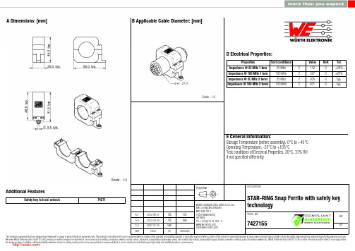
6.1 6.0 5.02012-06-272012-04-302007-01-25SStSStSMuSStSMu-Würth Elektronik eiSos GmbH & Co. KGEMC & Inductive SolutionsMax-Eyth-Str. 174638 WaldenburgGermanyTel. +49 (0) 79 42 945 - 0A Dimensions: [mm]Additional FeaturesSafety key to lock/ unkock74271D2 General Properties:Ferrite core Ferrite core Ferrite core Plastic housing Plastic housing Test cable Test cablePropertiesMaterial Initial permeability Curie temperatureColourFlammability ClassificationApplicable cable Applicable cable lengthµi T CValue 4 W 620620150Grey UL94-V0AWG26120Unit°Cmm Tol.typ.typ.F Typical Impedance Characteristics:I Cautions and Warnings:The following conditions apply to all goods within the product series of WE-STAR RINGof Würth Elektronik eiSos GmbH & Co. KG:General:All recommendations according to the general technical specifications of the data sheet have to be complied with.The disposal and operation of the product within ambient conditions which probably alloy or harm the component surface has to be avoided.The packaging of the product is to encase the needed humidity of the plastic housing. To ensure the humidity level, the products have to be stored in this delivered packaging. If not, the products are losing their humidity. In this case you can re-condition the components according to the internal standard WE1883 to ensure the necessary humidity in the plastic.To ensure the operating mode of the product, the ambient temperature at processing (when the part will be mounted on the cable) has to be in the range of 15 to 25 °C.Before mounting, the part should be stored for one hour in this condition.The responsibility for the applicability of customer specific products and the use in a particular customer design is always within the authority of the customer. All technical specifications for standard products do also apply for customer specific products.Direct mechanical impact to the product and the forcible closing of this shall be prevented as the ferrite material of the ferrite body or the pla-stic housing could flake or in the worst case it could break.Product specific:Follow all instructions mentioned in the datasheet, especially:•The cable diameter must be pointed out, otherwise no warranty will be sustained.•Violation of the technical product specifications such as exceeding the nominal rated current will result in the loss of warranty.1. General Customer ResponsibilitySome goods within the product range of Würth Elektronik eiSos GmbH & Co. KG contain statements regarding general suitability for certain application areas. These statements about suitability are based on our knowledge and experience of typical requirements concerning the are-as, serve as general guidance and cannot be estimated as binding statements about the suitability for a customer application. The responsibi-lity for the applicability and use in a particular customer design is always solely within the authority of the customer. Due to this fact it is up to the customer to evaluate, where appropriate to investigate and decide whether the device with the specific product characteristics described in the product specification is valid and suitable for the respective customer application or not.2. Customer Responsibility related to Specific, in particular Safety-Relevant ApplicationsIt has to be clearly pointed out that the possibility of a malfunction of electronic components or failure before the end of the usual lifetime can-not be completely eliminated in the current state of the art, even if the products are operated within the range of the specifications.In certain customer applications requiring a very high level of safety and especially in customer applications in which the malfunction or failure of an electronic component could endanger human life or health it must be ensured by most advanced technological aid of suitable design of the customer application that no injury or damage is caused to third parties in the event of malfunction or failure of an electronic component.3. Best Care and AttentionAny product-specific notes, warnings and cautions must be strictly observed.4. Customer Support for Product SpecificationsSome products within the product range may contain substances which are subject to restrictions in certain jurisdictions in order to serve spe-cific technical requirements. Necessary information is available on request. In this case the field sales engineer or the internal sales person in charge should be contacted who will be happy to support in this matter.5. Product R&DDue to constant product improvement product specifications may change from time to time. As a standard reporting procedure of the Product Change Notification (PCN) according to the JEDEC-Standard inform about minor and major changes. In case of further queries regarding the PCN, the field sales engineer or the internal sales person in charge should be contacted. The basic responsibility of the customer as per Secti-on 1 and 2 remains unaffected.6. Product Life CycleDue to technical progress and economical evaluation we also reserve the right to discontinue production and delivery of products. As a stan-dard reporting procedure of the Product Termination Notification (PTN) according to the JEDEC-Standard we will inform at an early stage about inevitable product discontinuance. According to this we cannot guarantee that all products within our product range will always be available. Therefore it needs to be verified with the field sales engineer or the internal sales person in charge about the current product availability ex-pectancy before or when the product for application design-in disposal is considered.The approach named above does not apply in the case of individual agreements deviating from the foregoing for customer-specific products.7. Property RightsAll the rights for contractual products produced by Würth Elektronik eiSos GmbH & Co. KG on the basis of ideas, development contracts as well as models or templates that are subject to copyright, patent or commercial protection supplied to the customer will remain with Würth Elektronik eiSos GmbH & Co. KG.8. General Terms and ConditionsUnless otherwise agreed in individual contracts, all orders are subject to the current version of the “General Terms and Conditions of Würth Elektronik eiSos Group”, last version available at .J Important Notes:The following conditions apply to all goods within the product range of Würth Elektronik eiSos GmbH & Co. KG:分销商库存信息: WURTH-ELECTRONICS 7427155。
5 x 20mm Fuses S505系列,时延式,陶瓷管说明书
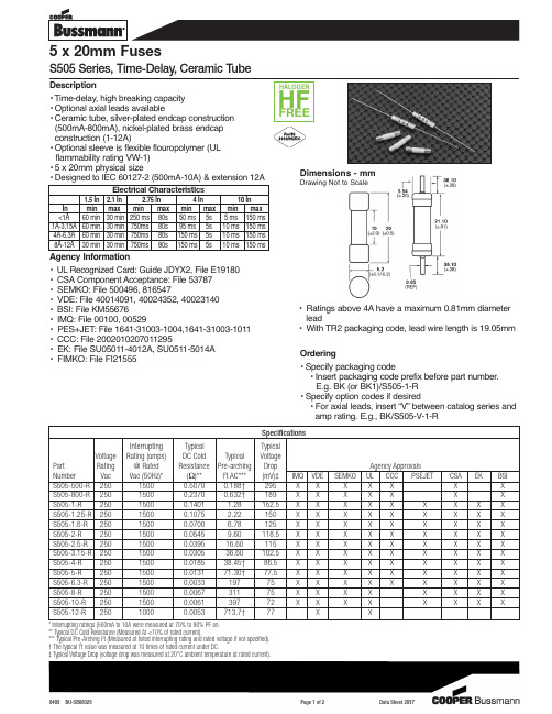
5 x 20mm FusesS505 Series, Time-Delay, Ceramic Tube0409 BU-SB08329Page 1 of 2Data Sheet 2037• Designed to IEC 60127-2 (500mA-10A) & extension 12AAgency Information•UL Recognized Card: Guide JDYX2, File E19180•CSA Component Acceptance: File 53787•SEMKO: File 500496, 816547•VDE: File 40014091, 40024352, 40023140•BSI: File KM55676•IMQ: File 00100, 00529• PES+JET : File 1641-31003-1004,1641-31003-1011 •CCC: File 2002010207011295• EK: File SU05011-4012A, SU0511-5014A • FIMKO: File FI21555Ordering• Specify packaging code• Insert packaging code prefix before part number.E.g. BK (or BK1)/S505-1-R • Specify option codes if desired• For axial leads, insert “V” between catalog series and amp rating. E.g., BK/S505-V-1-RDimensions - mmDrawing Not to ScaleSpecifications Interrupting Typical Typical Voltage Rating (amps)DC Cold Typical Voltage Part Rating @ Rated Resistance Pre-arching Drop Agency Approvals Number Vac Vac (50Hz)*(W )**I 2t AC***(mV)‡IMQVDE SEMKO UL CCC PSEJET CSA EKBSI S505-500-R 25015000.50700.188†295X X X X X X X S505-800-R 25015000.23700.632†189X X X X X X X S505-1-R 25015000.1401 1.28152.5X X X X X X X X X S505-1.25-R 25015000.1075 2.22150X X X X X X X X X S505-1.6-R 25015000.0700 6.78125X X X X X X X X X S505-2-R 25015000.05459.60118.5X X X X X X X X X S505-2.5-R 25015000.039516.60115X X X X X X X X X S505-3.15-R 25015000.030536.60102.5X X X X X X X X X S505-4-R 25015000.018538.45†86.5X X X X X X X X X S505-5-R 25015000.013171.30†77.5X X X X X X X X X S505-6.3-R 25015000.003319775X X X X X X X X X S505-8-R 25015000.006731175X X X X X X X X S505-10-R 25015000.006139772XX XX X XXXS505-12-R25010000.0053713.7†77XX* Interrupting ratings (500mA to 10A were measured at 70% to 80% PF on.** Typical DC Cold Resistance (Measured At <10% of rated current).*** Typical Pre-Arching I 2t (Measured at listed interrupting rating and rated voltage if not specified).† The typical I 2t value was measured at 10 times of rated current under DC.‡ Typical Voltage Drop (voltage drop was measured at 20°C ambient temperature at rated current).•Ratings above 4A have a maximum 0.81mm diameter lead•With TR2 packaging code, lead wire length is 19.05mmPackaging CodePackaging Code PrefixDescriptionBK 100 fuses packed into a cardboard carton BK11,000 fuses packed into a poly bagTR21,500 fuses packed into tape on a reel (19.05mm lead wire length)Option CodeOption CodeDescriptionVAxial leads - copper tinned wire with nickel plated brass overcapsThe only controlled copy of this Data Sheet is the electronic read-only version located on the Cooper Bussmann Network Drive.All other copies of this document are by definition uncontrolled.This bulletin is intended to clearly present comprehensive product data and provide technical information that will help the end user with design applications.Cooper Bussmann reserves the right,without notice,to change design or construction of any products and to discontinue or limit distribution of any products.Cooper Bussmann also reserves the right to change or update,without notice,any technical information contained in this bulletin.Once a product has been selected,it should be tested by the user in all possible applications.Life Support Policy:Cooper Bussmann does not authorize the use of any of its products for use in life support devices or systems without the express written approval of an officer of the Company.Life support systems are devices which support or sustain life,and whose failure to perform,when properly used in accordance with instructions for use provided in the labeling,can be reasonably expected to result in significant injury to the user.Current In AmpsT i m e I n S e c o n d sAmp Rating。
AT89S52系列规格书,Datasheet 资料

2.2 44-lead TQFP
2.3 44-lead PLCC
(MOSI) P1.5 7 (MISO) P1.6 8 (SCK) P1.7 9
RST 10 (RXD) P3.0 11
NC 12 (TXD) P3.1 13 (INT0) P3.2 14 (INT1) P3.3 15
(T0) P3.4 16 (T1) P3.5 17
VCC GND
RAM ADDR. REGISTER
P0.0 - P0.7 PORT 0 DRIVERS
P2.0 - P2.7 PORT 2 DRIVERS
RAM
PORT 0 LATCH
PORT 2 LATCH
FLASH
AT89S52
B REGISTER
ACC
STACK POINTER
PROGRAM ADDRESS REGISTER
4.4 Port 1
Port 1 is an 8-bit bidirectional I/O port with internal pull-ups. The Port 1 output buffers can sink/source four TTL inputs. When 1s are written to Port 1 pins, they are pulled high by the internal pull-ups and can be used as inputs. As inputs, Port 1 pins that are externally being pulled low will source current (IIL) because of the internal pull-ups.
SIMATIC S7-1500T CPU 1515T-2 PN 数据手册说明书
6ES7515-2TM01-0AB0
SIMATIC S7-1500T, CPU 1515T-2 PN, Central processing unit with work memory 750 KB for program and 3 MB for data, 1st interface: PROFINET IRT with 2-port switch, 2nd interface, Ethernet, 30 ns bit performance, SIMATIC Memory Card required
Power loss Power loss, typ.
Memory Number of slots for SIMATIC memory card SIMATIC memory card required Work memory ● integrated (for program) ● integrated (for data) Load memory ● Plug-in (SIMATIC Memory Card), max. Backup ● maintenance-free
PtP CM ● Number of PtP CMs
512 kbyte; In total; available retentive memory for bit memories, timers, counters, DBs, and technology data (axes): 472 KB 3 Mbyte; When using PS 6 0W 24/48/60 V DC HF
Configuration control
via dataset
Yes
Display Screen diagonal [cm]
CNOOC海洋平台阀门质量大纲
CNOOC 平台建造阀门质量大纲1.目的和适用范围1.1 本文件是方正阀门ISO9001-2008质量管理体系的补充,为CNOOC公司的石油平台、FPSO以及相关管道系统的阀门提供了设计和制造指南,以满足COOEC公司发布的设计文件的技术要求。
该要求包括COOEC规范以及一个或更多的COOEC强制性附加要求,这些要求应作为整体考虑。
1.2 当收到CNOOC的项目信息时,方正阀门销售工程师至少向采购方索求至少包括以下文件的技术资料:DD-DDS-GEN-PI-1001 DATASHEET FOR MANUAL VALVESDD-SPC-GEN-PI-1002 SPECIFICATION FOR PIPING MATERIALDD-SPC-GEN-PI-1012 SPECIFICATONFOR VALVE PURCHASE REQUIREMENTDD-SPC-GEN-CC-1001 SPECIFICAION FOR PROTECTIVE COATINGDD-SPC-GEN-PI-1015 SPECIFICATONFOR Fastenrt Coating所有文件需要抄送至:dcc@。
并在邮箱企业网盘中进行备案。
同时需要对升版文件进行及时更新,在客户询价或合同签订时一定要明确规格书的版次信息。
1.3 本质量大纲仅规定CL2500及以下的阀门,对于10000PSI级阀门不在本规范范围内。
2.引用文件DD-DDS-GEN-PI-1001 DATASHEET FOR MANUAL VALVESDD-SPC-GEN-PI-1002 SPECIFICATION FOR PIPING MATERIALDD-SPC-GEN-PI-1012 SPECIFICATONFOR VALVE PURCHASE REQUIREMENTDD-SPC-GEN-CC-1001 SPECIFICAION FOR PROTECTIVE COATINGDD-SPC-GEN-PI-1015 SPECIFICATONFOR FASTENRT COATING3.合同评审在收到CNOOC项目采购合同后,销售部应识别COOEC要求,并在“生产订单”项目名称一栏中注明“CNOOC+项目编号(如“LW3-1”)”。
PS22052资料

INSULATED TYPEINSULATED TYPEINSULATED TYPE3.43.22.92.2—0.73.80.71102.613.180.047mAV T j = 25°C T j = 125°CT j = 25°C T j = 125°CV CE(sat)V EC t on t rr t c(on)t off t c(off)I CESConditionSymbol ParameterLimits Inverter IGBT part (per 1/6 module)Inverter FWDi part (per 1/6 module)Case to fin, (per 1 module) thermal grease appliedR th(j-c)Q R th(j-c)F R th(c-f)Min.THERMAL RESISTANCETyp.Max.——————Unit –I C = 5A, V IN = 0VCondition Symbol ParameterLimits Min.Typ.Max.———0.8——————Unit ELECTRICAL CHARACTERISTICS (T j = 25°C, unless otherwise noted)INVERTER PARTCollector-emitter saturation voltageFWDi forward voltageJunction to case thermal resistanceV D = V DB = 15V V IN = 5V, I C = 5A Switching timesV CC = 600V, V D = V DB = 15VI C = 5A, T j = 125°C, V IN = 0 ↔ 5V Inductive load (upper-lower arm)Collector-emitter cut-off currentV CE = V CES2.72.52.41.50.20.42.80.4——V µs µs µs µs µs °C/W °C/W °C/WCONTROL (PROTECTION) PARTNote 4:Short circuit protection is functioning only at the low-arms. Please select the value of the external shunt resistor such that the SC trip-level is less than 1.7 times device current rating.5:Fault signal is output when the low-arms short circuit or control supply under-voltage protective functions operate. The fault output pulse-width t FO depends on the capacitance value of C FO according to the following approximate equation : C FO = 9.3 ✕ 10-6 ✕ t FO [F].SymbolI D V FOHV FOL V SC(ref)I INUV DBtUV DBrUV DtUV Drt FOV th(on)V th(off)ParameterConditionLimits Unit Circuit currentFault output voltageShort circuit trip levelSupply circuit under-voltage protection Fault output pulse width ON threshold voltage OFF threshold voltage V D = V DB = 15VV IN = 5V Total of V P1-V PC , V N1-V NC V UFB -V UFS , V VFB -V VFS , V WFB -V WFSV SC = 0V, F O circuit pull-up to 5V with 10k ΩV SC = 1V, I FO = 1mAT j = 25°C, V D = 15V (Note 4)V IN = 5VTrip level Reset levelTrip level Reset levelC FO = 22nF (Note 5)Applied between U P , V P , W P -V PC , U N , V N , W N -V NC————4.9—0.430.710.010.510.310.81.62.00.8——————0.481.5————2.43.01.43.701.303.501.30—1.100.532.012.012.512.513.0—4.22.0Min.Typ.Max.mA mA mA mA V V V mA V V V V ms V VV D = V DB = 15VV IN = 0V Total of V P1-V PC , V N1-V NC V UFB -V UFS , V VFB -V VFS , V WFB -V WFS T j ≤ 125°CNote 3:Grease with good thermal conductivity and long-term endurance should be applied evenly with about +100µm~+200µm on the con-tacting surface of DIP-IPM and heat-sink.Input current Contact thermal resistance (Note 3)INSULATED TYPEINSULATED TYPEINSULATED TYPEINSULATED TYPEINSULATED TYPE。
FLOJET T5000 Series CO2 Operated Bag-in-Box Pump说明

T5000 Seriesperformance andPump Features and Benefits324 1Applications• Designed for dispensing bag-in-box syrups, juiceconcentrate (without pulp or particulates), teas, wines, and liquor • Supplies the following from remote location: - Four (4) 3.0oz (89ml) valves 1 or - Two (2) 4.5oz (133ml) valves 21Each valve dispenses syrup at 0.50oz/sec 2Each valve dispenses syrup at 0.75oz/secTypical InstallationDimensional DrawingSpecificationsPump Design Positive Displacement, Double DiaphragmPower Source CO 2 Gas, Nitrogen or Compressed Filtered AirMaterials ofConstruction (Wetted Parts)Polypropylene, Santoprene®, EPDM, 302 or 304 Stainless Steel Spring Temperature Limits 34˚ - 120˚F (1.1˚ - 49˚C)Weight 1.19lbs (0.54kg)Dimensions 5.26" H x 6.18" W x 2.89" D(133.6mm x 156.8mm x 73.5mm)Displacement: 2.5 oz per cycle Self Priming Up to 10ft (3.05m)Operating Pressure 20 psi (1.4 bar) min / 80 psi (5.5 bar) maxFlow Rate 4.0oz (118.3ml)/sec - Open Flow Approvals CE, NSF Standard 18Warranty5 YearsNew Model No.ReplacesT5000-130N5000-130T5000-140N5000-140T5000-515N5000-515T5000-135 Service Pump (w/out auto shutoff)N5000-135T5000-153 High Altitude Pump or Installations Above 3000ft (900m)N5000-153Note: All N5000 Series pumps have been converted to T5000 series pumps per the part number format noted above.P/N 1521-000P/N 1520-000P/N 20607-100P/N 20608-100CO 2 SupplyFlojet Syrup Soldout Switch No. 2095-502Flojet Syrup Pump Model No. T5000-140Flojet Transfer ValveModel No.1500-0301500-031P/N 1510-000P/N 20606-100Flojet Brass CO2 Shutoff Valve1/2"(12.7 mm)1/4"(6.3 mm)1/4"(6.3 mm)1/4"(6.3 mm)1/4"(6.3 mm)P o s t M i x S y r u p J u i ceFlojet Stainless Steel Product In Port3/8"(9.5 mm) 6.18(157)Shown With Mounting Bracket(P/N 20272002)3.02(76.7)5.26(133.6)2.22(56.4)1.50(38.1)1.92(48.8).60(15.2)2.89(73.5)Dimensions in inches (mm)USAXylem, Inc.Cape Ann Industrial Park Gloucester, MA 01930 Tel (978) 281-0440Fax (978) 283-2619UKXylem, Inc.Bingley Road, Hoddesdon Hertfordshire EN11 OBU Tel +44 (0) 1992 450145Fax +44 (0) 1992 467132GERMANY Xylem, Inc.Oststrasse 2822844 Norderstedt Tel +49-40-53 53 73-0Fax +49-40-53 53 73-11JAPANNHK Jabsco Company Ltd.3-21-10, Shin-YokohamaKohoku-Ku, Yokohama, 222-0033Tel +81-045-475-8906Fax +81-045-477-1162ITALYXylem, Inc.Via Tommaseo, 620059 Vimercate, Milano Tel +39 039 685 2323Fax +39 039 666 307© 2012 Xylem, Inc. All rights reserved. Flojet is a trademark of Xylem Inc. or one of its subsidiaries.950-0146 Rev B. 1/12Warranty: All products of the company are sold and all services of the company are offered subject to the company’s warranty and terms and conditions of sale, copies of which will be furnished upon request. The information provided herein is for guidance only, it does not constitute a guarantee of the performance or specification of any individual product or component.。
