STM32系统----启动代码概述
STM32启动代码分析简化实战

STM32启动代码分析简化实战首先,我们来分析一下ST启动代码的结构。
通常,STM32的启动代码由两部分组成:启动文件和启动代码。
启动文件是一份汇编代码,其中定义了向量表、堆栈以及各个中断服务程序的跳转入口。
启动文件会在编译过程中被链接到用户程序的最起始处。
启动代码是一份C代码,用于初始化系统时钟和片上外设。
在启动文件的入口函数中,会调用启动代码的一些函数来完成这些初始化工作。
接下来,我们来看一下如何简化STM32启动代码。
通常情况下,启动代码会包含大量的初始化函数调用、配置寄存器的代码,这些代码会造成代码体积较大,且对于初学者来说,阅读和理解起来可能较为困难。
为了简化启动代码,我们可以使用CubeMX工具生成初始化代码。
CubeMX是ST官方提供的一款图形化工具,可以帮助我们自动生成初始化代码。
首先,我们需要安装并打开CubeMX工具。
然后,选择对应的MCU型号,并进行一些基本配置,如时钟源、系统频率等。
接下来,点击"Pinout & Configuration"选项卡,进行外设的配置。
可以选择需要使用的外设,并进行一些基本的参数设置。
完成配置后,点击"Project"选项卡,选择生成代码的目标IDE,比如Keil MDK、IAR Embedded Workbench等,并点击"Generate Code"按钮生成代码。
生成的代码将包含了系统时钟和外设的初始化代码,以及一些基本的配置文件,如头文件、链接脚本等。
最后,我们来进行一些实战演示。
以Blink LED为例,我们通过CubeMX生成初始化代码,并在主函数中添加LED闪烁的代码。
首先,在CubeMX中将GPIO口配置为输出模式,并选择对应的引脚和管脚模式。
生成代码后,在main.c文件中找到MX_GPIO_Init函数,将其中的代码复制到主函数中。
然后,在主函数中添加LED闪烁的代码,即将LED引脚设置为高电平后延时一段时间,然后将LED引脚设置为低电平再延时一段时间。
解析STM32启动过程

解析STM32启动过程
STM32启动过程是指当电源被接通时,STM32芯片进行自检并加载固
件的过程。
这个过程可以分为四个主要阶段:复位阶段、时钟初始化阶段、中断向量表重定位阶段和主函数执行阶段。
时钟初始化阶段是STM32启动的第二个阶段。
在复位阶段,系统时钟
会被配置为默认的内部RC振荡器,通常为8MHz。
在时钟初始化阶段,可
以通过程序代码来配置系统时钟,包括选择和配置时钟源、设置时钟分频等。
时钟的初始化是系统正常运行的前提条件,因为大多数外设的工作频
率都与系统时钟相关。
主函数执行阶段是STM32启动的最后一个阶段。
在中断向量表重定位
完成后,主函数会被调用执行。
主函数中通常会初始化系统的各种外设,
配置时钟、GPIO、中断等,并进入一个无限循环等待外设事件的发生。
一
旦外设事件发生,会触发中断,处理对应的中断服务程序。
总结来说,STM32启动过程包括复位阶段、时钟初始化阶段、中断向
量表重定位阶段和主函数执行阶段。
复位阶段进行系统自检和硬件初始化,时钟初始化阶段配置系统时钟,中断向量表重定位阶段将中断向量表重定
位到实际的起始地址,主函数执行阶段初始化外设并进入循环等待外设事
件的发生。
这个过程是STM32系统启动的基本过程,对于系统的正常运行
起着关键作用。
STM32启动文件:startup_stm32f10x_hd.s等启动文件的简单描述
STM32启动⽂件:startup_stm32f10x_hd.s等启动⽂件的简单描述在官⽅的库⽂件中,分别有如下⽂件:startup│││├─arm││││ startup_stm32f10x_cl.s││││ startup_stm32f10x_hd.s││││ startup_stm32f10x_hd_vl.s││││ startup_stm32f10x_ld.s││││ startup_stm32f10x_ld_vl.s││││ startup_stm32f10x_md.s││││ startup_stm32f10x_md_vl.s││││ startup_stm32f10x_xl.sR8T6使⽤的MD.s,中容量的arm芯⽚,⼤致的启动内容如下:初始化堆栈指针 SP初始化程序计数器指针 PC设置堆、栈的⼤⼩设置中断向量表的⼊⼝地址配置外部 SRAM 作为数据存储器调⽤ SystemInit() 函数配置 STM32 的系统时钟设置 C 库的分⽀⼊⼝ "__main” (最终⽤来调⽤ main 函数)startup_stm32f10x_hd.s 是⼀个启动⽂件,⾥⾯是使⽤汇编语⾔写好的基本程序,当STM32 芯⽚上电启动的时候,受限会执⾏这⾥的汇编程序,从⽽建⽴起来C 语⾔的运⾏环境,所以我们把这个⽂件称为启动⽂件。
改⽂件使⽤的汇编指令是 Cortex-M3 内核⽀持的指令,可以参考《Cortex-M3 权威指南中⽂》内指令集章节。
startup_stm32f10x_hd.s ⽂件是由ST官⽅提供的,该⽂件可以从KEIL5 安装⽬录中找到,也可以从STV3.5库⾥⾯找到,找到该⽂件后吧启动⽂件添加到⼯程⾥⾯即可。
不同型号的芯⽚以及不同编译环境使⽤的汇编⽂件是不⼀样的,但功能相同。
在keilMDK4中只有STM32F10x.s⽂件。
在<<STM32不完全⼿册⾥⾯>>,所有的例程都采⽤了⼀个叫STM32F10x.s的启动⽂件,⾥⾯定义了STM32的堆栈⼤⼩以及各种中断的名字及⼊⼝函数名称,还有启动相关的汇编代码。
stm32启动文件详解及SystemInit函数分析
DCD SysTick_Handler ; SysTick Handler
; External Interrupts
DCD WWDG_IRQHandler ; Window Watchdog
DCD PVD_IRQHandler ; PVD through EXTI Line detect
DCD TAMPER_IRQHandler ; Tamper
DCD RTC_IRQHandler ; RTC
DCD FLASH_IRQHandler ; Flash
;__main函数由编译器生成,负责初始化栈、堆等,并在最后跳转到用户自定义的main()函数,来到C的世界。
Stack_Size EQU 0x00000400 ;//定义堆栈大小
AREA STACK, NOINIT, READWRITE, ALIGN=3 ;//定义一个数据段 按8字节对齐 ;AREA 伪指令用于定义一个代码段或数据段 NOINIT:指定此数据段仅仅保留了内存单元,而没有将各初始值写入内存单元,或者将各个内存单元值初始化为0
;链接器检查要求堆栈八字节对齐的任何代码是否仅由保持堆栈八字节对齐的代码直接或间接地调用。
PRESERVE8 ;//指示编译器8字节对齐
Байду номын сангаас THUMB ;//指示编译器以后的指令为THUMB指令
;中断向量表定义
; Vector Table Mapped to Address 0 at Reset
;中断函数仅仅实现了Reset_Handler,其他要么是死循环,要么仅仅定义了函数名称
;STM32被设置为从内部FLASH启动时(这也是最常见的一种情况),当STM32遇到复位信号后,
解析STM32的启动过程
解析STM32的启动过程STM32的启动过程可以分为硬件启动过程和软件启动过程两部分。
硬件启动过程主要是指芯片上电后的初始化阶段,而软件启动过程则是指固定在芯片内的启动程序的执行过程。
硬件启动过程1.上电复位:当STM32芯片上电后,会进行一次复位操作,将片内的所有寄存器初始化为默认值。
2.时钟初始化:芯片复位后,需要初始化芯片的各个时钟源和时钟分频系数。
例如,配置系统时钟、外设时钟和外设时钟的分频。
3.外设初始化:初始化芯片的各个外设,包括GPIO、USART、SPI、I2C等。
外设初始化主要是配置相应的寄存器使它们能够正常工作。
4.中断向量表:中断向量表是储存在芯片中的一系列函数指针,用于响应中断事件。
在硬件启动过程中,需要将中断向量表的地址设定为固定的位置,并将其中各个中断的函数指针初始化为默认的中断服务函数。
5.系统堆栈初始化:系统堆栈是用于存储函数调用时的临时变量和程序返回地址的存储区域。
在硬件启动过程中,需要初始化系统堆栈指针,为后续的函数调用和中断处理做准备。
6. 程序复位:在芯片复位后,可以选择从外部存储器(如Flash)中加载启动程序,或从内部存储器(如内置Bootloader)中加载启动程序。
启动程序一般是一个二进制文件,其中包含了一系列的初始化指令和应用程序的入口点。
软件启动过程1.初始化函数:启动程序首先执行初始化函数,用于初始化C库、变量和硬件资源等。
例如,初始化堆栈指针、启动C库和启用FPU等。
2.系统时钟初始化:启动程序需要初始化系统时钟,以使系统能够正常工作。
这包括设置主时钟源、配置主时钟分频系数和外设时钟分频系数等。
3.初始化其他硬件资源:启动程序会初始化其他的硬件资源,例如外设、存储器、中断控制器等。
4.跳转到主函数入口点:启动程序最后一步是跳转到主函数的入口点,开始执行用户代码。
总结STM32的启动过程可以分为硬件启动过程和软件启动过程。
硬件启动过程包括上电复位、时钟初始化、外设初始化、中断向量表配置和系统堆栈初始化等操作。
stm32芯片初始控制码

stm32芯片初始控制码STM32芯片的初始控制码是用于初始化和配置芯片的一组指令。
这些指令在芯片上电后被执行,以确保芯片能够正常工作。
在开始编写初始控制码之前,我们需要了解芯片的基本信息,例如时钟频率、外设的配置等。
这些信息可以在芯片的数据手册中找到。
以下是一个示例的初始控制码,用于初始化STM32芯片:1. 设置系统时钟:- 配置时钟源,例如使用外部晶体振荡器或内部RC振荡器。
- 配置时钟分频器,例如设置主时钟频率为72MHz。
- 配置时钟系统,例如使能PLL锁相环。
2. 配置外设:- 配置GPIO引脚,例如设置某个引脚为输入或输出模式。
- 配置中断,例如使能某个引脚的中断功能。
- 配置定时器,例如设置定时器的时钟源和计数模式。
3. 初始化外设:- 初始化串口,例如配置波特率和数据位数。
- 初始化ADC,例如配置采样率和转换通道。
- 初始化DMA,例如配置传输方向和缓冲区地址。
4. 启动外设:- 启动定时器,例如使能定时器的计数功能。
- 启动ADC,例如使能ADC的转换功能。
- 启动DMA,例如使能DMA的传输功能。
5. 设置中断优先级:- 设置中断优先级,例如设置某个中断的优先级为高级或低级。
以上仅是一个示例,实际的初始控制码可能会根据具体的应用需求有所不同。
编写初始控制码时,需要根据芯片的数据手册和应用需求进行具体的配置和初始化。
需要注意的是,编写初始控制码需要一定的硬件和软件知识,并且需要仔细阅读芯片的数据手册以确保正确配置。
此外,初始控制码也需要根据具体的开发环境和开发工具进行调整和修改。
STM32 的三种不同启动模式

STM32 的三种不同启动模式STM32 三种启动模式对应的存储介质均是芯片内置的,它们是:1. 用户闪存:芯片内置的Flash。
2. SRAM:芯片内置的RAM 区,就是内存啦。
3. 系统存储器:芯片内部一块特定的区域,芯片出厂时在这个区域预置了一段Bootloader,就是通常说的ISP 程序。
这个区域的内容在芯片出厂后没有人能够修改或擦除,即它是一个ROM 区。
在每个STM32 的芯片上都有两个管脚BOOT0 和BOOT1,这两个管脚在芯片复位时的电平状态决定了芯片复位后从哪个区域开始执行程序,见下表:BOOT1=x BOOT0=0 从用户闪存启动,这是正常的工作模式。
BOOT1=0 BOOT0=1 从系统存储器启动,这种模式启动的程序功能由厂家设置。
BOOT1=1 BOOT0=1 从内置SRAM 启动,这种模式可以用于调试。
要注意的是,一般不使用内置SRAM 启动(BOOT1=1 BOOT0=1),因为SRAM 掉电后数据就丢失。
多数情况下SRAM 只是在调试时使用,也可以做其他一些用途。
如做故障的局部诊断,写一段小程序加载到SRAM 中诊断板上的其他电路,或用此方法读写板上的Flash 或EEPROM 等。
还可以通过这种方法解除内部Flash 的读写保护,当然解除读写保护的同时Flash 的内容也被自动清除,以防止恶意的软件拷贝。
STM32 PB2(BOOT1)使用注意由于STM32 PB2 脚是复用引脚,而且该复用功能是用于启动选择,使用时就要小心了。
-------------------------------------------------------------------------BOOT1 BOOT0 启动模式说明X 0 用户闪存存储器用户闪存存储器被选为启动区域0 1 系统存储器系统存储器被选为启动区域(进入ISP 模式)1 1 内嵌SRAM 内嵌SRAM 被选为启动区域-------------------------------- -----------------------------------------一般来讲我们正常使用是模式1(用户闪存存储。
STM32启动代码分析、简化、实战

本文通过对STM32的官方固件库STM32F10x_StdPeriph_Lib_V3.5.0里的MDK启动文件分析,简化部分不需要的代码,并从繁杂的固件库里,精炼出一个类似于“hello world”的入门实战小程序——点亮一个LED。
该工程仅仅包含一个启动文件和一个有main函数的C文件。
本文初衷:不用固件库建立自己的工程!实验软件:Keil uVision4实验硬件:神舟IV号开发板芯片型号:STM32F107VCSTM32启动代码分析、简化、实战汇编基础:1.伪指令:EQU语法格式:名称EQU表达式{,类型}EQU伪指令用于为程序中的常量、标号等定义一个等效的字符名称,类似于C语言的#define。
其中EQU可以用“*”代替。
名称为EQU伪指令定义的字符名称,当表达式为32位的常量时,可以指定表达式的数据类型,可以有一下三种类型:CODE16、CODE32和DA TA2.伪指令:AREA语法格式:AREA段名{,属性1}{,属性2}……AREA命令指示汇编程序汇编一个新的代码段或数据段。
段是独立的、指定的、不可见的代码或数据块,它们由链接程序处理。
段名:可以为段选择任何段名。
但是,以一个数字开始的名称必须包含在竖杠号内,否则会产生一个缺失段名错误。
例如,|1_DataArea|。
有些名称是习惯性的名称。
例如:|.text|用于表示由C编译程序产生的代码段,或用于以某种方式与C库关联的代码段。
属性字段表示该代码段(或数据段)的相关属性,多个属性用逗号分隔。
常用的属性如下:——CODE属性:用于定义代码段,默认为READONLY。
——DA TA属性:用于定义数据段,默认为READWRITE。
——READONLY属性:指定本段为只读,代码段默认为READONLY。
——READWRITE属性:指定本段为可读可写,数据段的默认属性为READWRITE。
——ALIGN属性:使用方式为ALIGN表达式。
一文了解STM32启动过程
一文了解STM32启动过程1 概述说明每一款(芯片)的启动文件都值得去研究,因为它可是你的程序跑的最初一段路,不可以不知道。
通过了解启动文件,我们可以体会到处理器的架构、指令集、中断向量安排等内容,是非常值得玩味的。
(STM32)作为一款高端Cortex-M3系列(单片机),有必要了解它的启动文件。
打好基础,为以后优化程序,写出高质量的代码最准备。
本文以一个实际测试代码--START_(TE)ST为例进行阐述。
整体过程STM32整个启动过程是指从上电开始,一直到运行到main 函数之间的这段过程,步骤为(以使用微库为例):①上电后(硬件)设置SP、PC②设置系统(时钟)③软件设置SP④加载.data、.bss,并初始化栈区⑤跳转到C文件的main函数代码启动过程涉及的文件不仅包含startup_stm32f10x_hd.s,还涉及到了MDK自带的连接库文件entry.o、entry2.o、entry5.o、entry7.o 等(从生成的map文件可以看出来)。
2 程序在Flash上的存储结构在真正讲解启动过程之前,先要讲解程序下载到Flash上的结构和程序运行时(执行到main函数)时的S(RAM)数据结构。
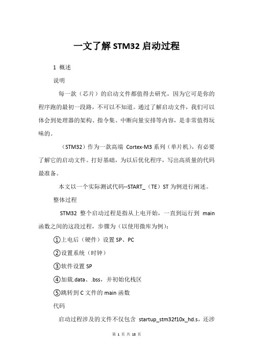
程序在用户Flash上的结构如下图所示。
下图是通过阅读hex文件和在MDK下调试综合提炼出来的。
上图中:MSP初始值由编译器生成,是主堆栈的初始值。
初始化数据段是.data未初始化数据段是.bss.data和.bss是在__main里进行初始化的,对于(ARM)Com (pi)ler,__main主要执行以下函数:其中__scatterlo(ad)会对.data和.bss进行初始化。
加载数据段和初始化栈的参数加载数据段和初始化栈的参数分别有4个,这里只讲解加载数据段的参数,至于初始化栈的参数类似。
0x0800033c Flash上的数据段(初始化数据段和未初始化数据段)起始地址0x20000000加载到SRAM上的目的地址0x0000000c数据段的总大小0x080002f4调用函数_scatterload_copy需要说明的是初始化栈的函数-- 0x08000304与加载数据段的函数不一样,为_scatterload_zeroinit,它的目的就是将栈空间清零。
stm32单片机开关代码
stm32单片机开关代码针对STM32单片机的开关控制代码,可以通过GPIO(通用输入/输出)模块来实现。
以下是一个简单的示例代码,用于控制单片机上的一个开关:c.#include "stm32f4xx.h"#define SWITCH_PIN GPIO_PIN_0。
#define SWITCH_PORT GPIOA.int main(void)。
{。
// 初始化时钟。
RCC->AHB1ENR |= RCC_AHB1ENR_GPIOAEN;// 配置GPIOA的PIN0为输入。
SWITCH_PORT->MODER &= ~(GPIO_MODER_MODE0); while (1)。
{。
// 读取开关状态。
if (SWITCH_PORT->IDR & SWITCH_PIN)。
{。
// 开关处于打开状态。
// 执行相应操作。
}。
else.{。
// 开关处于关闭状态。
// 执行相应操作。
}。
}。
}。
在这个示例代码中,我们首先包含了STM32F4系列的头文件,然后定义了开关所连接的引脚和端口。
在主函数中,我们启用了GPIOA的时钟,并将其PIN0配置为输入。
然后在一个无限循环中,我们不断地读取开关的状态,根据开关状态执行相应的操作。
需要注意的是,以上代码是一个简单的示例,实际的应用中可能需要考虑消抖、中断处理等更多的细节。
另外,具体的代码可能会因为使用的STM32型号和开发环境的不同而有所差异,需要根据具体情况进行调整。
希望以上信息能够帮助到你。
如果你需要更详细的代码或者其他方面的帮助,请随时告诉我。
STM32keil启动代码讲解

STM32keil启动代码讲解启动代码文件名是STM32F10X.S,它的作用先总结下,然后再分析。
启动代码作用一般是:1)堆和栈的初始化;2)向量表定义;3)地址重映射及中断向量表的转移;4)设置系统时钟频率;5)中断寄存器的初始化;6)进入C应用程序。
(1)按启动代码的次序,先看堆和栈的初始化:Stack_Size EQU 0x00000200 ;定义Stack_Size为0x00000200AREA STACK, NOINIT, READWRITE, ALIGN=3 ;定义栈,可初始为0,8字节对齐Stack_Mem SPACE Stack_Size ;分配0x200个连续字节,并初始化为0 __initial_sp ;汇编代码地址标号Heap_Size EQU 0x00000000AREA HEAP, NOINIT, READWRITE, ALIGN=3__heap_baseHeap_Mem SPACE Heap_Size__heap_limitPRESERVE8 ;指定当前文件堆栈8字节对齐THUMB ;告诉汇编器下面是32为的Thumb指令,如果需要汇编器将插入位以保证对齐(2)中断向量表定义AREA RESET, DA TA, READONLY ;定义复位向量段,只读EXPORT __V ectors ;定义一个可以在其他文件中使用的全局标号。
此处表示中断地址__V ectors DCD __initial_sp ; 给__initial_sp分配4字节32位的地址0x0DCD Reset_Handler ; 给标号Reset Handler分配地址为0x00000004DCD NMI_Handler ; 给标号NMI Handler分配地址0x00000008DCD HardFault_Handler ; Hard Fault HandlerDCD MemManage_Handler ; MPU Fault HandlerDCD BusFault_Handler ; Bus Fault HandlerDCD UsageFault_Handler ; Usage Fault HandlerDCD 0 ; 这种形式就是保留地址,不给任何标号分配DCD 0 ; ReservedDCD 0 ; ReservedDCD 0 ; ReservedDCD SVC_Handler ; SVCall HandlerDCD DebugMon_Handler ; Debug Monitor HandlerDCD 0 ; ReservedDCD PendSV_Handler ; PendSV HandlerDCD SysTick_Handler ; SysTick Handler; External InterruptsDCD WWDG_IRQHandler ; Window WatchdogDCD PVD_IRQHandler ; PVD through EXTI Line detectDCD TAMPER_IRQHandler ; TamperDCD RTC_IRQHandler ; RTCDCD FLASH_IRQHandler ; FlashDCD RCC_IRQHandler ; RCCDCD EXTI0_IRQHandler ; EXTI Line 0DCD EXTI1_IRQHandler ; EXTI Line 1DCD EXTI2_IRQHandler ; EXTI Line 2DCD EXTI3_IRQHandler ; EXTI Line 3DCD EXTI4_IRQHandler ; EXTI Line 4DCD DMAChannel1_IRQHandler ; DMA Channel 1DCD DMAChannel2_IRQHandler ; DMA Channel 2DCD DMAChannel3_IRQHandler ; DMA Channel 3DCD DMAChannel4_IRQHandler ; DMA Channel 4DCD DMAChannel5_IRQHandler ; DMA Channel 5DCD DMAChannel6_IRQHandler ; DMA Channel 6DCD DMAChannel7_IRQHandler ; DMA Channel 7DCD ADC_IRQHandler ; ADCDCD USB_HP_CAN_TX_IRQHandler ; USB High Priority or CAN TXDCD USB_LP_CAN_RX0_IRQHandler ; USB Low Priority or CAN RX0DCD CAN_RX1_IRQHandler ; CAN RX1DCD CAN_SCE_IRQHandler ; CAN SCEDCD EXTI9_5_IRQHandler ; EXTI Line 9..5DCD TIM1_BRK_IRQHandler ; TIM1 BreakDCD TIM1_UP_IRQHandler ; TIM1 UpdateDCD TIM1_TRG_COM_IRQHandler ; TIM1 Trigger and CommutationDCD TIM1_CC_IRQHandler ; TIM1 Capture CompareDCD TIM2_IRQHandler ; TIM2DCD TIM3_IRQHandler ; TIM3DCD TIM4_IRQHandler ; TIM4DCD I2C1_EV_IRQHandler ; I2C1 EventDCD I2C1_ER_IRQHandler ; I2C1 ErrorDCD I2C2_EV_IRQHandler ; I2C2 EventDCD I2C2_ER_IRQHandler ; I2C2 ErrorDCD SPI1_IRQHandler ; SPI1DCD SPI2_IRQHandler ; SPI2DCD USART1_IRQHandler ; USART1DCD USART2_IRQHandler ; USART2DCD USART3_IRQHandler ; USART3DCD EXTI15_10_IRQHandler ; EXTI Line 15..10DCD RTCAlarm_IRQHandler ; RTC Alarm through EXTI LineDCD USBWakeUp_IRQHandler ; USB Wakeup from suspend(3)中断向量表的转移AREA|.text|, CODE, READONLY;代码段定义; Reset HandlerReset_Handler PROC ;标记一个函数的开始EXPORT Reset_Handler [WEAK];[WEAK] 选项表示当所有的源文件都没有定义这样一个标号时,编译器也不给出错误信息,在多数情况下将该标号置为0 ,若该标号为 B 或BL 指令引用,则将 B 或BL指令置为NOP 操作。
STM32启动代码

March 2010Doc ID 13801 Rev 61/20AN2606Application noteSTM32™ microcontrollersystem memory boot modeIntroductionThe bootloader is stored in the internal boot ROM memory (system memory) of STM32 devices. It is programmed by ST during production. Its main task is to download the application program to the internal Flash memory through one of the available serial peripherals (USART, CAN, USB, etc.). A communication protocol is defined for each serial interface, with a compatible command set and sequences.The main features of the bootloader are the following:●It uses an embedded serial interface to download the code with a predefined communication protocol ●It transfers and updates the Flash memory code, the data, and the vector table sections This application note presents the general concept of the bootloader. It describes the supported peripherals and hardware requirements to be considered when using the bootloader of any STM32 device currently in production. However the specifications of the low-level communication protocol for each supported serial peripheral are documented in separate documents:●For specifications of the USART protocol used in the bootloader please refer to AN3155●For the specification of CAN protocol used in the bootloader please refer to AN3154●For the specification of DFU (USB Device) protocol used in the bootloader please refer to AN3156Related documentsAvailable from :●STM32 datasheets:–low-, medium- and high-density STM32F101xx and STM32F103xx datasheets –low- and medium-density STM32F100xx and STM32F102xx datasheets –STM32F105xx/107xx connectivity line datasheet●STM32 reference manuals:–STM32F101xx, STM32F102xx, STM32F103xx and STM32F105xx/107xxreference manual (RM0008)–low- and medium-density STM32F100xx value line reference manual (RM0041)●STM32 Flash programming manuals –STM32F101xx, STM32F102xx, STM32F103xx and STM32F105xx/107xx Flashprogramming manual (PM0042)–low- and medium-density STM32F100xx value line Flash programming manual(PM0063)Contents AN2606Contents1General bootloader description . . . . . . . . . . . . . . . . . . . . . . . . . . . . . . . . 61.1Bootloader activation . . . . . . . . . . . . . . . . . . . . . . . . . . . . . . . . . . . . . . . . . 61.2Exiting system memory boot mode . . . . . . . . . . . . . . . . . . . . . . . . . . . . . . 61.3Bootloader identification . . . . . . . . . . . . . . . . . . . . . . . . . . . . . . . . . . . . . . . 6 2STM32F101xx, STM32F102xx, STM32F103xx andmedium-density value line bootloader . . . . . . . . . . . . . . . . . . . . . . . . . . 82.1Bootloader configuration . . . . . . . . . . . . . . . . . . . . . . . . . . . . . . . . . . . . . . 82.2Bootloader hardware requirements . . . . . . . . . . . . . . . . . . . . . . . . . . . . . . 92.3Bootloader selection . . . . . . . . . . . . . . . . . . . . . . . . . . . . . . . . . . . . . . . . . . 92.4Bootloader version . . . . . . . . . . . . . . . . . . . . . . . . . . . . . . . . . . . . . . . . . . 103STM32F105xx and STM32F107xx device bootloader . . . . . . . . . . . . . . 113.1Bootloader configuration . . . . . . . . . . . . . . . . . . . . . . . . . . . . . . . . . . . . . 113.2Bootloader hardware requirements . . . . . . . . . . . . . . . . . . . . . . . . . . . . . 133.3Bootloader selection . . . . . . . . . . . . . . . . . . . . . . . . . . . . . . . . . . . . . . . . . 143.4Bootloader version . . . . . . . . . . . . . . . . . . . . . . . . . . . . . . . . . . . . . . . . . . 15 4Device-dependent bootloader parameters . . . . . . . . . . . . . . . . . . . . . . 17 Revision history . . . . . . . . . . . . . . . . . . . . . . . . . . . . . . . . . . . . . . . . . . . . . . . . . . . . 182/20Doc ID 13801 Rev 5AN2606List of tables List of tablesTable 1.Boot pin configuration. . . . . . . . . . . . . . . . . . . . . . . . . . . . . . . . . . . . . . . . . . . . . . . . . . . . . . 6 Table 2.Embedded bootloaders. . . . . . . . . . . . . . . . . . . . . . . . . . . . . . . . . . . . . . . . . . . . . . . . . . . . . 7 Table 3.STM32F10xxx configuration in system memory boot mode. . . . . . . . . . . . . . . . . . . . . . . . . 8 Table 4.STM32F10xxx bootloader versions evolution. . . . . . . . . . . . . . . . . . . . . . . . . . . . . . . . . . . 10 Table 5.STM32F105xx/107xx configuration in system memory boot mode . . . . . . . . . . . . . . . . . . 11 Table 6.STM32F105xx and STM32F107xx Bootloader versions evolution. . . . . . . . . . . . . . . . . . . 16 Table 7.Bootloader device dependant parameters . . . . . . . . . . . . . . . . . . . . . . . . . . . . . . . . . . . . . 17 Table 8.Document revision history . . . . . . . . . . . . . . . . . . . . . . . . . . . . . . . . . . . . . . . . . . . . . . . . . 18Doc ID 13801 Rev 53/20List of figures AN2606 List of figuresFigure 1.Bootloader for STM32 with USART1 . . . . . . . . . . . . . . . . . . . . . . . . . . . . . . . . . . . . . . . . . . 9 Figure 2.Bootloader selection. . . . . . . . . . . . . . . . . . . . . . . . . . . . . . . . . . . . . . . . . . . . . . . . . . . . . . 15 4/20Doc ID 13801 Rev 5AN2606GlossaryLow-density devices are STM32F101xx, STM32F102xx and STM32F103xxmicrocontrollers where the Flash memory density ranges between 16 and 32 Kbytes.Medium-density devices are STM32F101xx, STM32F102xx and STM32F103xxmicrocontrollers where the Flash memory density ranges between 64 and 128 Kbytes.High-density devices are STM32F101xx and STM32F103xx microcontrollers where theFlash memory density ranges between 256 and 512 Kbytes.Connectivity line devices are STM32F105xx and STM32F107xx microcontrollers.Low-density value line devices are STM32F100xx microcontrollers where the Flashmemory density ranges between 16 and 32 Kbytes.Medium-density value line devices are STM32F100xx microcontrollers where the Flashmemory density ranges between 64 and 128 Kbytes.Doc ID 13801 Rev 55/206/20Doc ID 13801 Rev 51 General bootloader description1.1 Bootloader activationThe bootloader is automatically activated by configuring the BOOT0 and BOOT1 pins in thespecific “System memory” configuration (see T able 1) and then by applying a reset.Depending on the used pin configuration, the Flash memory, system memory or SRAM isselected as the boot space, as shown in Table 1 below.Table 1 shows that the STM32 microcontrollers enter the System memory boot mode if theBOOT pins are configured as follows:●BOOT0 = 1 ●BOOT1 = 0The values on the BOOT pins are latched on the fourth rising edge of SYSCLK after a reset.1.2 Exiting system memory boot modeSystem memory boot mode must be exited in order to start execution of the applicationprogram. This can be done by applying a hardware reset. During reset, the BOOT pins(BOOT0 and BOOT1) must be set at the proper levels to select the desired boot mode (seeTable 1). Following the reset, the CPU starts code execution from the boot memory locatedat the bottom of the memory address space starting from 0x00000000.1.3 Bootloader identificationDepending on the used STM32 device, the bootloader may support one or more embeddedserial peripherals used to download the code to the internal Flash memory. The bootloaderidentifier (ID) provides information about the supported serial peripherals.For a given STM32 device, the bootloader is identified by means of the:Table 1.Boot pin configurationBoot mode selection pinsBoot mode Aliasing BOOT1BOOT0X0User Flash memory User Flash memory is selected as the boot space 01System memory System memory is selected as the boot space 11Embedded SRAM Embedded SRAM is selected as the boot spaceDoc ID 13801 Rev 57/201.Bootloader (protocol) version : version of the serial peripheral (USART, CAN, USB,etc.) communication protocol used in the bootloader. This version can be retrievedusing the bootloader Get Version command.2. Bootloader identifier (ID): version of the STM32 device bootloader, coded on one bytein the 0xXY format , where:–X specifies the embedded serial peripheral(s) used by the device bootloader:X = 1: only one USART is usedX = 2: two USARTs are usedX = 3 two USARTs, one CAN and DFU are used–Y specifies the device bootloader versionLet us take the example of a bootloader ID equal to 0x10. This means that it is thefirst version of the device bootloader that uses only one USART.The bootloader ID is programmed in the last two bytes of the device systemmemory and can be read by using the bootloader “Read memory” command or bydirect access to the system memory via JTAG/SWD.The table below provides identification information about the bootloader embedded inSTM32 devices.Table 2.Embedded bootloaders DeviceSupported serial peripherals Bootloader ID Bootloader (protocol) version ID Memory location Low-densityUSART1NA NA USART (V2.2)Medium-densityUSART1NA NA USART (V2.2)High-density USART1NA NA USART (V2.2)Connectivity line USART1 / USART2 (remapped) / CAN2 (remapped) / DFU (USB Device)NA NA USART(V2.2(1))CAN (V2.0)DFU(V2.0)1.For connectivity line devices, the USART bootloader returns V2.0 instead of V2.2 for the protocol version. For more details please refer to the "STM32F105xx and STM32F107xx revision Z" errata sheet available from .Medium-densityvalue line USART1V1.00x1FFFF7D6USART (V2.2)8/20Doc ID 13801 Rev 52 ST M32F101xx, ST M 32F102xx, STM32F103xx and medium-density value line bootloaderThroughout this section STM32F10xxx will be used to refer to low-density, medium-density,high-density STM32F101xx and STM32F103xx devices, to low- and medium-densitySTM32F102xx devices and to medium-density value line devices.2.1 Bootloader configurationThe bootloader embedded in STM32F10xxx devices uses configuration 1, which means thatonly the USART1 peripheral is supported.The following table shows the required STM32F10xxx hardware resources used by thebootloader in System memory boot mode.Table 3.STM32F10xxx configuration in system memory boot modeNote:1The system clock is derived from the embedded internal high-speed RC, no external quartz is required for the bootloader code 2After downloading the application binary, if you choose to execute the Go command, theperipheral registers used by the bootloader (shown in the above table) are not initialized totheir default reset values before jumping to the user application. They should bereconfigured in the user application if they are used. So, if the IWDG is being used in theapplication, the IWDG prescaler value has to be adapted to meet the requirements of theapplication (since the prescaler was set to its maximum value by the bootloader).Feature/PeripheralState Comment Clock sourceHSI enabled The system clock is equal to 24 MHz using the PLL USART1_RX pinInput P A10 pin: USART1 receives USART1_TX pinOutput P A9 pin: USART1 transmits SysTick timerEnabled Used to automatically detect the serial baud rate from the ART1Enabled Once initialized the USART1 configuration is: 8-bits, even parity and 1 Stop bit RAM-512 bytes starting from address 0x2000 0000 are used by the bootloader firmware System memory - 2 Kbytes starting from address 0x1FFF F000, contain thebootloader firmwareIWDG -The independent watchdog (IWDG) prescaler is configured to its maximum value and is periodically refreshed to preventwatchdog reset (in case the hardware IWDG option waspreviously enabled by the user)2.2 Bootloader hardware requirementsThe hardware required to put the STM32 into System memory boot mode consists of anycircuitry, switch or jumper, capable of holding the BOOT0 pin high and the BOOT1 pin lowduring reset.To connect to the STM32 during System memory boot mode, an RS232 serial interface(example, ST3232 RS232 transceiver) has to be directly linked to the USART1_RX (PA10)and USART1_TX (PA9) pins.Note:USART1_CK, USART1_CTS and USART1_RTS pins are not used, therefore user can use these pins for other peripherals or GPIOs.3For more details about hardware recommendations, refer to application note AN2586: “STM32 hardware development: getting started”, available from the STMicroelectronicswebsite: 2.3 BootloaderselectionDoc ID 13801 Rev 59/20Once System memory boot mode is entered and the microcontroller has been configured asdescribed above, the bootloader code begins to scan the USART1_RX line pin, waiting toreceive the 0x7F data frame: one start bit, 0x7F data bits, even parity bit and one stop bit.The duration of this data frame is measured using the Systick timer. The count value of thetimer is then used to calculate the corresponding baud rate factor with respect to the currentsystem clock.Next, the code initializes the serial interface accordingly. Using this calculated baud rate, anacknowledge byte (0x79) is returned to the host, which signals that the STM32F10xxx isready to receive user commands.2.4 BootloaderversionThe Table4 lists the bootloader versions evolution of the STM32F10xxx devices.Table 4.STM32F10xxx bootloader versions evolutionBootloader version number DescriptionV2.0Initial bootloader version.V2.1–Update Go Command to initialize the main stack pointer–Update Go command to return NACK when jump address is in the Option byte area or System memory area–Update Get ID command to return the device ID on two bytes –Update the bootloader version to V2.1V2.2– Update Read Memory, Write Memory and Go commands to deny access with a NACK response to the first 0x200 bytes of RAM memory used by the bootloader–Update Readout Unprotect command to initialize the whole RAM content to 0x0 before ROP disable operation10/20Doc ID 13801 Rev 53 STM32F105xx and STM32F107xx device bootloader 3.1 BootloaderconfigurationThe bootloader embedded in the STM32F105xx and STM32F107xx devices usesconfiguration 2. This means that four serial peripherals are supported: USART1, USART2,CAN2 and DFU (USB).The following table shows the hardware resources required by STM32F105xx andSTM32F107xx devices used by the bootloader in System memory boot mode.Table 5.STM32F105xx/107xx configuration in system memory boot modeBootloader Feature/Peripheral State CommentCommon to all bootloaders RCCHSI enabledThe system clock frequency is 24 MHz using the PLL.This is used only for USART1 and USART2bootloaders and during CAN2, USB detection forCAN and DFU bootloaders (Once CAN or DFUbootloader is selected, the clock source will bederived from external crystal).HSE enabledThe external clock is mandatory only for DFU andCAN bootloaders and it must provide one of thefollowing frequencies: 8 MHz, 14.7456 MHz or25MHz.For CAN Bootloader, the PLL is used only to generate48MHz when 14.7456MHz is used as HSE.For DFU Bootloader, the PLL is used to generate a48MHz system clock from all supported externalclock frequencies.-The clock security system (CSS) interrupt is enabledfor the CAN and DFU bootloaders. Any failure (orremoval) of the external clock will generate systemreset.IWDG-The independent watchdog (IWDG) prescaler isconfigured to its maximum value and is periodicallyrefreshed to prevent watchdog reset (in case thehardware IWDG option was previously enabled by theuser).System memory-18 Kbytes starting from address 0x1FFF B000,contain the bootloader firmwareRAM-4 Kbytes starting from address 0x2000 0000 are usedby the bootloader firmware.USART1 bootloader USART1EnabledOnce initialized the USART1 configuration is: 8-bits,even parity and 1 Stop bitUSART1_RX pin Input P A10 pin: USART1 receiveUSART1_TX pin Output P A9 pin: USART1 transmitUSART2_RX (PD6), CAN2_RX (PB5), OTG_FS_DM (P A11) and OTG_FS_DP (P A12) pins must be kept at a high or low level during the detection phase.Doc ID 13801 Rev 511/2012/20Doc ID 13801 Rev 5The system clock is derived from the embedded internal high-speed RC for USARTxbootloader. This internal clock is used also for DFU and CAN bootloaders but only for theselection phase. An external clock (8 MHz, 14.7456 MHz or 25 MHz.) is required for DFUand CAN bootloader execution after the selection phase.After downloading the application binary, if you choose to execute the Go command, allperipheral registers used by the bootloader (shown in the above table) will be initialized totheir default reset values before jumping to the user application.If the user application uses the IWDG, the IWDG prescaler value has to be adapted to meetthe requirements of the application (since the prescaler was set to its maximum value by thebootloader).USART1 and USART2 bootloaders SysTick timer Enabled Used to automatically detect the serial baud rate fromthe host for USARTx bootloader.USART2 bootloader USART2Enabled Once initialized the USART2 configuration is: 8-bits,even parity and 1 Stop bit. The USART2 uses itsremapped pins.USART2_RX pinInput PD6 pin: USART2 receive (remapped pin)USART2_TX pin OutputPD5 pin: USART2 transmit (remapped pin)USART1_RX (P A10), CAN2_RX (PB5), OTG_FS_DM (P A11) and OTG_FS_DP (P A12) pins mustbe kept at a high or low level during the detection phase.CAN2 bootloader CAN2Enabled Once initialized the CAN2 configuration is: Baudrate125 kbps, 11-bit identifier.Note: CAN1 is clocked during the CAN bootloaderexecution because in STM32F105xx andSTM32F107xx devices, CAN1 manages thecommunication between CAN2 and SRAM.CAN2_RX pin Input PB5 pin: CAN2 receives (remapped pin)CAN2_TX pin OutputPB6 pin: CAN2 transmits (remapped pin)USART1_RX (P A10), USART2_RX (PD6), OTG_FS_DM (P A11) and OTG_FS_DP (P A12) pinsmust be kept at a high or low level during the detection phase.DFUbootloader USB OTG FS Enabled USB OTG FS configured in Forced device modeOTG_FS_VBUS pin Input or alternate function, automatically controlled by the USB OTG FS controller P A9: Power supply voltage line OTG_FS_DM pin P A11: USB Send-Receive data line OTG_FS_DP pin P A12: USB Send-Receive data lineInterrupts Enabled USB_OTG_FS interrupt vector is enabled and usedfor USB DFU communication.USART1_RX (P A10), USART2_RX (PD6) and CAN2_RX (PB5) pins must be kept at a high or lowlevel during the detection phase.Table 5.STM32F105xx/107xx configuration in system memory boot mode (continued)Bootloader Feature/PeripheralState Comment3.2 Bootloader hardware requirementsThe hardware required to put the STM32F105xx and STM32F107xx into System memoryboot mode consists of any circuitry, switch or jumper, capable of holding the BOOT0 pin highand the BOOT1 pin low during reset.To connect to the STM32F105xx and STM32F107xx during System memory boot mode, thefollowing conditions have to be verified:●The RX pins of the unused peripherals in this bootloader have to be kept at a known(low or high) level, and should not be left floating during the detection phase asdescribed below:–If USART1 is used to connect to the bootloader: the USART2_RX (PD6),CAN2_RX (PB5), OTG_FS_DM (PA11) and OTG_FS_DP (PA12) pins have to bekept at a high or low level and must not be left floating during the detection phase.–If USART2 is used to connect to the bootloader: the USART1_RX (PA10),CAN2_RX (PB5), OTG_FS_DM (PA11) and OTG_FS_DP (PA12) pins have to bekept at a high or low level and must not be left floating during the detection phase.–If CAN2 is used to connect to the bootloader: the USART1_RX (PA10),USART2_RX (PD6), OTG_FS_DM (PA11) and OTG_FS_DP (PA12) pins have tobe kept at a high or low level and must not be left floating during the detectionphase.–If DFU is used to connect to the bootloader: the USART1_RX (PA10),USART2_RX (PD6) and CAN2_RX (PB5) pins have to be kept at a high or lowlevel and must not be left floating during the detection phase.●Connect to the peripheral to be used through:–an RS232 serial interface (example, ST3232 RS232 transceiver) has to be directly connected to the USART1_RX (PA10) and USART1_TX (PA9) pins whenUSART1 is used, or to the USART2_RX (PD6) and USART2_TX (PD5) pins whenUSART2 is used– a CAN interface (CAN transceiver) has to be directly connected to the CAN2_RX (PB5) and CAN2_TX (PB6) pins– a certified USB cable has to be connected to the microcontroller (optionally an ESD protection circuitry can be used)The USART1_CK, USART1_CTS and USART1_RTS pins are not used, therefore theapplication can use these pins for other peripherals or GPIOs. The same note is applicablefor USART2.Once the USB Device is enabled, all its related pins are dedicated to USB communicationonly, and cannot be used for other application purposes.The user can control the BOOT0 and Reset pins from a PC serial applet using the RS232serial interface which controls BOOT0 through the CTS line and Reset through the DCDline. The user must use a full null modem cable. The necessary hardware to implement forthis control exists in the STM3210C-EVAL board. For more details about this, refer todocument: “STM3210C-EVAL board user manual”, available from the STMicroelectronicswebsite: .Doc ID 13801 Rev 513/203.3 BootloaderselectionThe STM32F105xx and STM32F107xx embedded bootloader supports four peripheralsinterfaces: USART1, USART2, CAN2 and DFU (USB). Any one of these peripheralinterfaces can be used to communicate with the bootloader and download the applicationcode to the internal Flash.The embedded bootloader firmware is able to auto-detect the peripheral interface to beused. In an infinite loop, it detects any communication on the supported bootloaderinterfaces.Note:The RX pins of the unused peripherals in this bootloader have to be maintained at a known (low or high) level and should not be left floating during the detection phase as describedbelow:●If USART1 is used to connect to the bootloader: the USART2_RX (PD6), CAN2_RX(PB5), OTG_FS_DM (PA11) and OTG_FS_DP (PA12) pins have to be kept at a high orlow level and must not be left floating during the detection phase.●If USART2 is used to connect to the bootloader: the USART1_RX (PA10), CAN2_RX(PB5), OTG_FS_DM (PA11) and OTG_FS_DP (PA12) pins have to be kept at a high orlow level and must not be left floating during the detection phase.●If CAN2 is used to connect to the bootloader: USART1_RX (PA10), USART2_RX(PD6), OTG_FS_DM (PA11) and OTG_FS_DP (PA12) pins have to be kept at a high orlow level and must not be left floating during the detection phase.●If DFU is used to connect to the bootloader: the USART1_RX (PA10), USART2_RX(PD6) and CAN2_RX (PB5) pins have to be kept at a high or low level and must not beleft floating during the detection phase.To use the USART bootloader on USART1 or USART2, connect the serial cable to thedesired interface. Once the bootloader detects the data byte 0x7F on this interface, thebootloader firmware executes the auto-baud rate sequence and then enters a loop, waitingfor any USART bootloader command.To use the CAN2 interface, connect the CAN cable to CAN2. Once the bootloader detects aframe on the CAN2_RX pin (PB5), the bootloader firmware enters a CAN loop and starts tocheck the external clock frequency value, if the HSE is 8 MHz, 14.7456 MHz or 25 MHzCAN bootloader firmware enters an infinite loop and waits until it receives a message,otherwise a system reset is generated.If a USB cable is plugged into the microcontroller’s USB interface at any time during thebootloader firmware selection sequence, the bootloader then enters the DFU bootloaderloop waiting for any DFU bootloader command.To use the USART or the CAN bootloader, it is mandatory that no USB cable is connected tothe USB peripheral during the selection phase. Once the USART or CAN bootloader isselected, the user can plug a USB cable without impacting the selected bootloaderexecution except commands which generate a system reset.Once one interface is selected for the bootloader, all other interfaces are disabled.The figure below shows the bootloader detection mechanism. More details are provided inthe sections corresponding to each peripheral bootloader.14/20Doc ID 13801 Rev 5Doc ID 13801 Rev 515/20Figure 2.Bootloader selection 3.4 Bootloader versionThe table below lists the bootloader versions and the changes between versions V1.0 andV2.0. of the STM32F105xx and STM32F107xx devicesS y s tem re s etS y s tem init (clock, GPIO s , IWDG,S y s Tick)0x7F received onU S ART1Y e sNo 0x7F received onU S ART2Y e s No Config u re U S ART2Config u re U S ART1Config u re CAN2Config u re U S BFr a me detected onCAN2_RX pinNo Exec u teBL_U S ART_Loop forU S ART2Exec u teBL_U S ART_Loop forU S ART1Y e sExec u te BL_CAN_Loop forCAN2U S B c ab ledetectedReconfig u re s y s tem clock to 48 MHz a nd U S B clock to 48 MHz Exec u te DFU b oot-lo a der us ing U S B interr u pt s H S E = 8 MHz,14.7456 MHz or25 MHzY e sH S E = 8 MHz, 14.7456 MHz or 25 MHz Y e s No Y e s Gener a te s y s temre s et No Gener a te s y s tem re s et No a i17514Table 6.STM32F105xx and STM32F107xx Bootloader versions evolution Bootloader versionnumberDescriptionV1.0Initial bootloader version.V2.0– Bootloader detection mechanism updated to fix the issue when GPIOs of unused peripherals in this bootloader are connected to low level or left floating during the detection phase.For more details please refer to limitation 2.12 “Boot loader unavailability on STM32F105xx and STM32F107xx devices with a date code below 937” as described in Revision 2 of the “STM32F105xx and STM32F107xx revision Z” errata sheet available from –Vector table set to 0x1FFF B000 instead of 0x00000000–Go command updated (for all bootloaders): USART1, USART2, CAN2, GPIOA, GPIOB, GPIOD and SysTick peripheral registers are set to their default reset values–DFU bootloader: USB pending interrupt cleared before executing the Leave DFU command–DFU subprotocol version changed from V1.0 to V1.2–Bootloader version updated to V2.016/20Doc ID 13801 Rev 5AN2606Device-dependent bootloader parameters Doc ID 13801 Rev 517/204 Device-dependent bootloader parametersThe bootloader protocol’s command set and sequences for each serial peripheral (USART,CAN and USB) are the same for all STM32 devices. Some parameters, however, aredevice-dependent. For a few commands, the value of some parameters may depend on thedevice used. These parameters are listed below:●PID (product ID), which changes with the device ●Valid memory addresses (RAM, Flash memory, system memory, option byte area) accepted by the bootloader when the Read Memory, Go and Write Memory commandsare accepted.●Size of the Flash memory sector used when executing the Write Protect command.The table below shows the values of these parameters for each STM32 device bootloader inproduction.Table 7.Bootloader device dependant parameters DeviceProduct (device) ID RAM memory Flash memory Flash sector size Option byte area System memory Low-density0x4120x20000200 up to 0x200028000x08000000 up to 0x08008000 4 Kbytes (4 pages of 1 Kbyte each)0x1FFFF800 - 0x1FFFF80F 0x1FFFF000 - 0x1FFFF800Medium-density 0x4100x20000200 up to 0x200050000x08000000 up to 0x08020000 4 Kbytes (4 pages of 1 Kbyte each)0x1FFFF800 - 0x1FFFF80F 0x1FFFF000 -0x1FFFF800High-density 0x4140x20000200 up to 0x200100000x08000000 up to 0x08080000 4 Kbytes (2 pages of 2Kbytes each)0x1FFFF800 - 0x1FFFF80F 0x1FFFF000 -0x1FFFF800Connectivity line 0x4180x20001000 up to 0x200100000x08000000 up to 0x08040000 4 Kbytes (2 pages of 2Kbytes each)0x1FFFF800 - 0x1FFFF80F 0x1FFFB000- 0x1FFFF800Medium-densityvalue line 0x4200x20000200 up to 0x200020000x08000000 up to 0x08020000 4 Kbytes (4 pages of 1 Kbyte each)0x1FFFF800 - 0x1FFFF80F 0x1FFFF000 -0x1FFFF800。
STM32的启动
STM32的启动1、启动⽂件简介 启动⽂件由汇编编写,是系统上电复位后第⼀个执⾏的程序。
主要做了以下⼯作: (1)初始化堆栈指针 MSP=_initial_sp (2)初始化 PC 指针=Reset_Handler (3)初始化中断向量表 (4)配置系统时钟 (5)调⽤ C 库函数_main 初始化⽤户堆栈,从⽽最终调⽤ main 函数去到 C 的世界2、STM32的启动流程 下⾯这段话引⽤⾃《CM3 权威指南 CnR2》—复位序列, CM4 的复位序列跟 CM3 ⼀样。
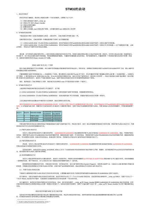
在离开复位状态后, CM3 做的第⼀件事就是读取下列两个 32 位整数的值: (1)从地址 0x0000,0000(FLASH 的地址 0x08000000,因为STM32设计的Flash起始地址是在0x0800 0000开始的)处取出 MSP 的初始值。
(2)从地址 0x0000,0004(FLASH 的地址 0x08000004,因为STM32设计的Flash起始地址是在0x0800 0000开始的)处取出 PC 的初始值——这个值是复位向量, LSB 必须是1,然后从这个值所对应的地址处取值。
请注意,这与传统的 ARM 架构不同——其实也和绝⼤多数的其它单⽚机不同。
传统的 ARM 架构总是从 0 地址开始执⾏第⼀条指令。
它们的 0 地址处总是⼀条跳转指令。
在CM3 中,在 0 地址处提供 MSP 的初始值,然后紧跟着就是向量表。
向量表中的数值是 32位的地址,⽽不是跳转指令。
向量表的第⼀个条⽬指向复位后应执⾏的第⼀条指令,就是我们刚刚分析的 Reset_Handler 这个函数。
初始化 MSP 和 PC 的⼀个范例 因为 CM3 使⽤的是向下⽣长的满栈,所以 MSP 的初始值必须是堆栈内存的末地址加1。
举例来说,如果我们的堆栈区域在 0x20007C00-0x20007FFF 之间,那么 MSP 的初始值就必须是 0x20008000。
STM32启动文件详解及SystemInit函数分析

1/6/afeibfp/archive/2013/01/08/2850408.html <2013年1月>日一二三四五六303112345678910111213141516171819202122232425262728293031123456789昵称:afeibfp 园龄:2年5个月粉丝:0关注:0+加关注搜索找找看 谷歌搜索常用链接我的随笔我的评论我的参与最新评论我的标签更多链接我的标签51单片机(2)多字节除法(2)汇编(2)随笔分类(2)转发(2)随笔档案(16)2013年1月 (14)2011年9月 (2)最新评论1. Re:014:针对mdk 中STM32程序无法使用printf ,产生停留BEAB BKPT 0xAB 处问题的解决(转)不点那个MiclroLIB 就行了--blakeliu阅读排行榜1. 001:无符号双字节除以单字节(51单片机,汇编源码)(418)2. 004:STM32启动文件详解及SystemInit 函数分析(转)(389)3. 014:针对mdk 中STM32程序无法使用printf ,产生停留BE AB BKPT 0xAB 处问题的解决(转)(312)4. 010:请教STM32用JLINK V8 SWD 输出调试信息到ITM V iewer 的问题(转)(208)5. 009:semihost/ITM 机制浅析以及使用JLINK 通过ITM 调试stm32单片机(转)(190)评论排行榜1. 014:针对mdk 中STM32程序无法使用printf ,产生停留BE AB BKPT 0xAB 处问题的解决(转)(1)2. 013:ADS semihosting 与硬件重定向(转)(0)3. 012:Keil 调试技术(转)(0)4. 011:Nuvoton(新唐) Cort ex M0 使用semihost 输入输出办法(转)(0)5. 010:请教STM32用JLINK V8 SWD 输出调试信息到ITM V iewer 的问题(转)(0)推荐排行榜博客园首页新随笔联系管理订阅 随笔- 16 文章- 0 评论- 1afeibfp004:STM32启动文件详解及SystemInit 函数分析(转)1 ;先在R A M 中分配系统使用的栈,R A M 的起始地址为0x 2000_00002 ;然后在R A M 中分配变量使用的堆3 ;然后在C O D E 区(f l a s h )分配中断向量表,f l a s h 的起始地址为0x 0800_0000,该中断向量表就从这个起始地址开始分配4 ;分配完成后,再定义和实现相应的中断函数,5 ;所有的中断函数全部带有[w e a k ]特性,即弱定义,如果编译器发现在别处文件中定义了同名函数,在链接时用别处的地址进行链接。
stm32启动文件详解

STM32启动文件详解一、启动文件的作用1.初始化堆栈指针 SP;2.初始化程序计数器指针 PC;3.设置堆、栈的大小;4.设置异常向量表的入口地址;5.配置外部 SRAM作为数据存储器(这个由用户配置,一般的开发板可没有外部SRAM);6.设置 C库的分支入口__main(最终用来调用 main函数);7.在 3.5版的启动文件还调用了在 system_stm32f10x.c文件中的SystemIni()函数配置系统时钟。
二、汇编指令三、启动代码1.stack ----- 栈Stack_Size EQU 0x00000400 ; 栈的大小AREA STACK, NOINIT, READWRITE,ALIGN=3 Stack_Mem SPACE Stack_Size ; 分配栈空间__initial_sp ; 栈的结束地址(栈顶地址) 分配名为STACK,不初始化,可读可写,8(2^3)字节对齐的1KB空间。
栈:局部变量,函数形参等。
栈的大小不能超过内部SRAM大小。
AREA:汇编一个新的代码段或者数据段。
STACK段名,任意命名;NOINIT表示不初始化;READWRITE可读可写;ALIGN=3(2^3= 8字节对齐)。
__initial_sp紧挨了SPACE放置,表示栈的结束地址,栈是从高往低生长,结束地址就是栈顶地址。
2.heap ----- 堆Heap_Size EQU 0x00000200 ; 堆的大小(512Bytes)AREA HEAP, NOINIT, READWRITE,ALIGN=3__heap_base ; 堆的起始地址Heap_Mem SPACE Heap_Size ; 分配堆空间__heap_limit ; 堆的结束地址分配名为HEAP,不初始化,可读可写,8(2^3)字节对齐的512字节空间。
__heap_base堆的起始地址,__heap_limit堆的结束地址。
STM32启动代码详细分析

STM32启动代码详细分析最近需要学习iap的功能,因此离不开stm32的启动代码的分析,以前看了很多遍,都看不懂,读书百遍,其义⾃见,因此我有看了⼀遍,下⾯的⽂章,挺好的,因此转载:在上电复位后,我们都知道会先运⾏启动代码,但是启动代码到底使⼲什么⽤的呢?下⾯⼩弟给⼤家⼀⼀列出来。
1、初始化堆栈指针2、初始化 PC 指针3、初始化中断向量表4、配置系统时钟5、调⽤ C 库函数_main 初始化⽤户堆栈我们根据这以上的⼏个步骤⼀⼀进⾏详细的解析:1、栈的内存分配这段代码的意思是,开辟了⼀个栈,这个栈的⼤⼩是0x00000400也就是1KB的⼤⼩,名字为STACK,不初始化,可读可写,2^3=8字节对齐。
那么问题来了,那这个栈到底使⼲什么的呢?⼩弟相信⼤家在学习C语⾔的时候应该也是知道了,栈区保存的是局部变量,只是当时并没有深⼊研究它的⼤⼩问题。
那在这⾥⼩弟给⼤家详细讲解⼀下栈的作⽤:1、局部变量2、函数调⽤3、函数形参以上的这三种情况的开销都是使⽤我们的栈区的资源的。
所以啊!这⾥⼩弟给个位提个醒,千万不要把栈区当成⽆⽌境⼤⼩的哦!STM32可不⽐我们的电脑,没有那么多的空间可以给⼤伙挥霍,如果我们定义的局部变量过⼤可是会莫名其妙报错的。
温馨提⽰:请不要在写程序时,过度使⽤局部变量,会造成栈的益处,从⽽导致编译报错,如果在特殊情况下真的需要很⼤的栈区空间,只需来这⾥进⾏栈区⼤⼩的修改即可。
那么⼩弟再来给这个程序段⾥的汇编指令做⼀个详细的介绍Stack_Size EQU 0x00000400EQU:宏定义的伪指令,相当于等于,类似与 C 中的 define。
这句话的意思是,定义⼀个宏名Stack_Size这个宏代表0x00000400的意思,⽤我们C语⾔来表⽰就是#define Stack_Size 0x00000400AREA STACK, NOINIT, READWRITE, ALIGN=3AREA:告诉汇编器汇编⼀个新的代码段或者数据段。
STM32启动代码和BootLoder
一、启动代码当前的嵌入式应用程序开发过程里,并且C语言成为了绝大部分场合的最佳选择。
如此一来main函数似乎成为了理所当然的起点——因为C程序往往从main函数开始执行。
但一个经常会被忽略的问题是:微控制器(单片机)上电后,是如何寻找到并执行main函数的呢?很显然微控制器无法从硬件上定位main函数的入口地址,因为使用C语言作为开发语言后,变量/函数的地址便由编译器在编译时自行分配,这样一来main函数的入口地址在微控制器的内部存储空间中不再是绝对不变的。
相信读者都可以回答这个问题,答案也许大同小异,但肯定都有个关键词,叫“启动文件”。
也即启动代码。
启动代码是系统上电或者复位后运行的第一段代码,是进入C 语言的main 函数之前需要执行的那段汇编代码。
它的作用是在用户程序运行之前对系统硬件及软件环境进行必要的初始化并在最后使程序跳转到用户程序。
无论性能高下,结构简繁,价格贵贱,每一种微控制器(处理器)都必须有启动文件,启动文件的作用便是负责执行微控制器从“复位”到“开始执行main函数”中间这段时间(称为启动过程)所必须进行的工作。
最为常见的51,A VR或MSP430等微控制器当然也有对应启动文件,但开发环境往往自动完整地提供了这个启动文件,不需要开发人员再行干预启动过程,只需要从main函数开始进行应用程序的设计即可。
话题转到STM32微控制器,无论是keiluvision4还是IAR EW ARM开发环境,ST公司都提供了现成的直接可用的启动文件,程序开发人员可以直接引用启动文件后直接进行C 应用程序的开发。
这样能大大减小开发人员从其它微控制器平台跳转至STM32平台,也降低了适应STM32微控制器的难度。
相对于ARM上一代的主流ARM7/ARM9内核架构,新一代Cortex内核架构的启动方式有了比较大的变化。
ARM7/ARM9内核的控制器在复位后,CPU会从存储空间的绝对地址0x000000取出第一条指令执行复位中断服务程序的方式启动,即固定了复位后的起始地址为0x000000(PC = 0x000000)同时中断向量表的位置并不是固定的。
linux Gcc下开发stm32的启动代码

Gcc 环境下stm32开发笔记最近在移植公司的系统到stm32中,发现该系统使用的是gcc 开发的,可是一般情况下stm32都是在集成环境下开发的,这时候就有很多以前集成开发环境做的事情需要我们自己编写makefile ,链接器脚本和启动代码。
由于公司的启动代码部分是采用C语言编写的,但是我不喜欢C的启动代码,所以我查阅了相关资料,把keil里面自带的启动代码,经过转换,转化成在gcc 下可以用的启动代码,本文中所有的代码经过编译,运行成功的,最后在C环境下点亮LED等来显示效果,需要完成这些功能至少需要以下几个文件Start.s main.csystem_stm32f10x.c stm32f10x_rcc.c stm32f10x_gpio.c,以及st标准库的所有头文件以防编译出错。
Gcc 开发最主要的要完成3个步骤,搭建起C语言的编程环境,其他的任何平台都是一样的。
这3个步骤分别是,编写链接脚本,编写Makefile ,编写启动代码,这些完成了之后,以后的开发工作就都是一样的了。
闲话不说,首先我们把链接脚本贴上来。
/*宏定义处理器架构为arm*/OUTPUT_ARCH(arm)/*定义入口函数*/ENTRY(Reset_Handler)/*定义内存组织结构*/MEMORY{/*我用的芯片是stm32f103 内存32K Flash 512K*/RAM(xrw) : ORIGIN = 0x20000000,LENGTH = 32KFLASH(rx): ORIGIN = 0x08000000,LENGTH = 512K}/*定义代码段*/SECTIONS{/*代码最开头部分是中断向量表*/. = ALIGN(4); /*4字节对齐*/.text :{KEEP(*(.isr_vector))*(.text)} > FLASH. = ALIGN(4);__etext = .; /*代码段结束 . 代表单前地址*/ /*定义数据段*/.data : AT (__etext){__data_start__ = .;*(vtable)*(.data*). = ALIGN(4);PROVIDE (__preinit_array_start = .);*(.preinit_array)PROVIDE (__preinit_array_end = .);. = ALIGN(4);PROVIDE (__init_array_start = .);*(SORT(.init_array.*))*(.init_array)PROVIDE (__init_array_end = .);. = ALIGN(4);PROVIDE (__fini_array_start = .);*(SORT(.fini_array.*))*(.fini_array)PROVIDE (__fini_array_end = .);. = ALIGN(4);__data_end__ = .;} > RAM/*定义bss 段 bss 为未初始化的变量*/ . = ALIGN(4);.bss :{__bss_start__ = .;*(.bss)__bss_end__ = .;} > RAM/*定义堆区*/. = ALIGN(4);.heap :{__end__ = .;end = __end__;*(.heap*)__HeapLimit = .;} > RAM/*定义栈区*/.stack_dummy :{*(.stack)} > RAM__StackTop = ORIGIN(RAM) + LENGTH(RAM);__StackLimit = __StackTop - SIZEOF(.stack_dummy);PROVIDE(__stack = __StackTop);/*检查数据+堆+栈是否超出RAM*/ASSERT(__StackLimit >= __HeapLimit, "region RAM overflowed with stack") }有了链接脚本我们就需要编写一个Makefile 了 ,Makefile的目录结构请各位自己定义,这里的目录结构仅供参考。
STM32启动模式说明

STM32启动模式说明 渤海三叠浪 理论部分理论部分Boot mode selection pins Boot mode AliasingBOOT1 BOOT0X 0 User Flash memory X 0 User Flash memory User Flash memory is selected as the boot space User Flash memory is selected as the boot space 0 1 System memory 0 1 System memory System memory is selected as the boot space System memory is selected as the boot space1 1 Embedded SRAM 1 1 Embedded SRAM Embedded SRAM is selected as Embedded SRAM is selected as Embedded SRAM is selected as the boot space the boot space the boot space《STM32三种启动模式中存储器的存储介质三种启动模式中存储器的存储介质》》引自STM32的博客STM32三种启动模式对应的存储介质均是芯片内置的三种启动模式对应的存储介质均是芯片内置的,,它们是它们是::1)用户闪存用户闪存 = = = 芯片内置的芯片内置的Flash Flash。
2)SRAM = SRAM = 芯片内置的芯片内置的RAM 区,就是内存啦就是内存啦。
3)系统存储器系统存储器 = = = 芯片内部一块特定的区域芯片内部一块特定的区域芯片内部一块特定的区域,,芯片出厂时在这个区域预置了一段Bootloader Bootloader,,就是通常说的ISP 程序程序。
这个区域的内容在芯片出厂后没有人能够在芯片出厂后没有人能够修改或擦除修改或擦除修改或擦除,,即它是一个ROM 区。
STM32F407启动代码分析

;定义栈段,不初始化(只分配空间不做初始化或者初始化为零)Stack_Size EQU 0x00000400 ;#define Stack_Size ox00000400,EQU---arm汇编的预定义AREA STACK, NOINIT, READWRITE, ALIGN=3 ;段的开始,段名STACK,段属性NOINIT, ALIIGNStack_Mem SPACE Stack_Size;分配栈存储空间大小为ox00000400(1K),SPACE 分配连续存储单元,__initial_sp;栈空间顶地址; <h> Heap Configuration; <o> Heap Size (in Bytes) <0x0-0xFFFFFFFF:8>; </h>;开辟一段大小为Heap_base的内存空间作为堆Heap_Size EQU 0x00000200;#define Heap_Size ox00000200AREA HEAP, NOINIT, READWRITE, ALIGN=3;HEAP段,NOINIT只分配空间不做初始化或初始化为零;可读可写,按八字节对齐__heap_base ;堆起始地址Heap_Mem SPACE Heap_Size;分配堆空间大小为0x00000200__heap_limit ;堆终止地址PRESERVE8;告诉编译器以八字节对齐THUMB;告诉编译器使用THUMB指令集;定义复位段(中断向量表),并初始化; Vector Table Mapped to Address 0 at ResetAREA RESET, DA TA, READONL Y;定义RESET段,数据段,之都EXPORT __Vectors;声明全局变量_Vectors,该标号可在其他文件中使用,中断向量表入口地址EXPORT __Vectors_End;向量表终止地址EXPORT __Vectors_Size;向量表空间大小;DCD用于分配一段字内存单元(分配的内存以字对齐)__Vectors DCD __initial_sp ; Top of Stack 内存块起始地址标号为_Vectors,栈顶地址DCD Reset_Handler ; Reset Handler接下来到AREA |.text|, CODE, READONL Y都是建立中断向量表DCD NMI_Handler ; NMI HandlerDCD HardFault_Handler ; Hard Fault HandlerDCD MemManage_Handler ; MPU Fault HandlerDCD BusFault_Handler ; Bus Fault HandlerDCD UsageFault_Handler ; Usage Fault HandlerDCD 0 ; ReservedDCD 0 ; ReservedDCD 0 ; ReservedDCD 0 ; ReservedDCD SVC_Handler ; SVCall HandlerDCD DebugMon_Handler ; Debug Monitor HandlerDCD 0 ; ReservedDCD PendSV_Handler ; PendSV HandlerDCD SysTick_Handler ; SysTick Handler; External Interrupts外部中断DCD WWDG_IRQHandler ; Window WatchDogDCD PVD_IRQHandler ; PVD through EXTI Line detectionDCD TAMP_STAMP_IRQHandler ; Tamper and TimeStamps through the EXTI lineDCD RTC_WKUP_IRQHandler ; RTC Wakeup through the EXTI lineDCD FLASH_IRQHandler ; FLASHDCD RCC_IRQHandler ; RCCDCD EXTI0_IRQHandler ; EXTI Line0DCD EXTI1_IRQHandler ; EXTI Line1DCD EXTI2_IRQHandler ; EXTI Line2DCD EXTI3_IRQHandler ; EXTI Line3DCD EXTI4_IRQHandler ; EXTI Line4DCD DMA1_Stream0_IRQHandler ; DMA1 Stream 0DCD DMA1_Stream1_IRQHandler ; DMA1 Stream 1DCD DMA1_Stream2_IRQHandler ; DMA1 Stream 2DCD DMA1_Stream3_IRQHandler ; DMA1 Stream 3DCD DMA1_Stream4_IRQHandler ; DMA1 Stream 4DCD DMA1_Stream5_IRQHandler ; DMA1 Stream 5DCD DMA1_Stream6_IRQHandler ; DMA1 Stream 6DCD ADC_IRQHandler ; ADC1, ADC2 and ADC3sDCD CAN1_TX_IRQHandler ; CAN1 TXDCD CAN1_RX0_IRQHandler ; CAN1 RX0DCD CAN1_RX1_IRQHandler ; CAN1 RX1DCD CAN1_SCE_IRQHandler ; CAN1 SCEDCD EXTI9_5_IRQHandler ; External Line[9:5]sDCD TIM1_BRK_TIM9_IRQHandler ; TIM1 Break and TIM9DCD TIM1_UP_TIM10_IRQHandler ; TIM1 Update and TIM10DCD TIM1_TRG_COM_TIM11_IRQHandler ; TIM1 Trigger and Commutation and TIM11DCD TIM1_CC_IRQHandler ; TIM1 Capture CompareDCD TIM2_IRQHandler ; TIM2DCD TIM3_IRQHandler ; TIM3DCD TIM4_IRQHandler ; TIM4DCD I2C1_EV_IRQHandler ; I2C1 EventDCD I2C1_ER_IRQHandler ; I2C1 ErrorDCD I2C2_EV_IRQHandler ; I2C2 EventDCD I2C2_ER_IRQHandler ; I2C2 ErrorDCD SPI1_IRQHandler ; SPI1DCD SPI2_IRQHandler ; SPI2DCD USART1_IRQHandler ; USART1DCD USART2_IRQHandler ; USART2DCD USART3_IRQHandler ; USART3DCD EXTI15_10_IRQHandler ; External Line[15:10]sDCD RTC_Alarm_IRQHandler ; RTC Alarm (A and B) through EXTI LineDCD OTG_FS_WKUP_IRQHandler ; USB OTG FS Wakeup through EXTI lineDCD TIM8_BRK_TIM12_IRQHandler ; TIM8 Break and TIM12DCD TIM8_UP_TIM13_IRQHandler ; TIM8 Update and TIM13DCD TIM8_TRG_COM_TIM14_IRQHandler ; TIM8 Trigger and Commutation and TIM14DCD TIM8_CC_IRQHandler ; TIM8 Capture CompareDCD DMA1_Stream7_IRQHandler ; DMA1 Stream7DCD FSMC_IRQHandler ; FSMCDCD SDIO_IRQHandler ; SDIODCD TIM5_IRQHandler ; TIM5DCD SPI3_IRQHandler ; SPI3DCD UART4_IRQHandler ; UART4DCD UART5_IRQHandler ; UART5DCD TIM6_DAC_IRQHandler ; TIM6 and DAC1&2 underrun errorsDCD TIM7_IRQHandler ; TIM7DCD DMA2_Stream0_IRQHandler ; DMA2 Stream 0DCD DMA2_Stream1_IRQHandler ; DMA2 Stream 1DCD DMA2_Stream2_IRQHandler ; DMA2 Stream 2DCD DMA2_Stream3_IRQHandler ; DMA2 Stream 3DCD DMA2_Stream4_IRQHandler ; DMA2 Stream 4DCD ETH_IRQHandler ; EthernetDCD ETH_WKUP_IRQHandler ; Ethernet Wakeup through EXTI lineDCD CAN2_TX_IRQHandler ; CAN2 TXDCD CAN2_RX0_IRQHandler ; CAN2 RX0DCD CAN2_RX1_IRQHandler ; CAN2 RX1DCD CAN2_SCE_IRQHandler ; CAN2 SCEDCD OTG_FS_IRQHandler ; USB OTG FSDCD DMA2_Stream5_IRQHandler ; DMA2 Stream 5DCD DMA2_Stream6_IRQHandler ; DMA2 Stream 6DCD DMA2_Stream7_IRQHandler ; DMA2 Stream 7DCD USART6_IRQHandler ; USART6DCD I2C3_EV_IRQHandler ; I2C3 eventDCD I2C3_ER_IRQHandler ; I2C3 errorDCD OTG_HS_EP1_OUT_IRQHandle; USB OTG HS End Point 1 OutDCD OTG_HS_EP1_IN_IRQHandler ; USB OTG HS End Point 1 InDCD OTG_HS_WKUP_IRQHandler ; USB OTG HS Wakeup through EXTIDCD OTG_HS_IRQHandler ; USB OTG HSDCD DCMI_IRQHandler ; DCMIDCD CRYP_IRQHandler ; CRYP cryptoDCD HASH_RNG_IRQHandler ; Hash and RngDCD FPU_IRQHandler ; FPU__Vectors_End ;中断向量表结束地址__Vectors_Size EQU __Vectors_End - __Vectors ;#define __Vectors_Size __Vectors_End - __Vectors;定义代码段(异常处理函数),并进行初始化AREA |.text|, CODE, READONLY; |.text|习惯性命名,表示由C编译程序产生的代码段,或用于以某种方式与C库关联的代码段; Reset handler 复位处理函数Reset_Handler PROCEXPORT Reset_Handler [WEAK]IMPORT SystemInit ;引入外部定义的SystemInit函数IMPORT __main;引入外部定义的_main函数;FPU settings 单精度浮点单元设置LDR R0, =0xE000ED88 ; Enable CP10,CP11 R0=0xE000ED88LDR R1,[R0] ;R1=[R0],将0xE000ED88地址下内容加载到R1内,即R1=0xE000ED88地址下的值ORR R1,R1,#(0xF << 20);R1=R1|(0xF << 20)即将R1的[20:23]置为1STR R1,[R0];[R0]=R1,将R1寄存器的内容写到R0寄存器内的数据所代表的地址下LDR R0, =SystemInit ;R0=SystemInitBLX R0 ;跳转到SystemInit地址处,执行SystemInit函数,并由ARM 切换到THUMB状态,并将PC当前内容保存到R14中LDR R0, =__main;R0=_main,即将_main函数地址赋给R0BX R0; 跳转到_main地址处执行,并且根据R0的最低位切换处理器状态ENDP;从Reset_Handler PROC到ENDP表示复位处理子程序; Dummy Exception Handlers (infinite loops which can be modified)NMI_Handler PROCEXPORT NMI_Handler [WEAK]B .ENDPHardFault_Handler\PROCEXPORT HardFault_Handler [WEAK]B .ENDPMemManage_Handler\PROCEXPORT MemManage_Handler [WEAK]B .ENDPBusFault_Handler\PROCEXPORT BusFault_Handler [WEAK]B .ENDPUsageFault_Handler\PROCEXPORT UsageFault_Handler [WEAK]B .ENDPSVC_Handler PROCEXPORT SVC_Handler [WEAK]B .ENDPDebugMon_Handler\PROCEXPORT DebugMon_Handler [WEAK]B .ENDPPendSV_Handler PROCEXPORT PendSV_Handler [WEAK]B .ENDPSysTick_Handler PROCEXPORT SysTick_Handler [WEAK]B .ENDPDefault_Handler PROC ;这个异常处理函数会处理所有外部中断EXPORT WWDG_IRQHandler [WEAK] EXPORT PVD_IRQHandler [WEAK] EXPORT TAMP_STAMP_IRQHandler [WEAK] EXPORT RTC_WKUP_IRQHandler [WEAK] EXPORT FLASH_IRQHandler [WEAK] EXPORT RCC_IRQHandler [WEAK] EXPORT EXTI0_IRQHandler [WEAK] EXPORT EXTI1_IRQHandler [WEAK] EXPORT EXTI2_IRQHandler [WEAK] EXPORT EXTI3_IRQHandler [WEAK] EXPORT EXTI4_IRQHandler [WEAK] EXPORT DMA1_Stream0_IRQHandler [WEAK] EXPORT DMA1_Stream1_IRQHandler [WEAK] EXPORT DMA1_Stream2_IRQHandler [WEAK] EXPORT DMA1_Stream3_IRQHandler [WEAK] EXPORT DMA1_Stream4_IRQHandler [WEAK] EXPORT DMA1_Stream5_IRQHandler [WEAK] EXPORT DMA1_Stream6_IRQHandler [WEAK] EXPORT ADC_IRQHandler [WEAK] EXPORT CAN1_TX_IRQHandler [WEAK] EXPORT CAN1_RX0_IRQHandler [WEAK] EXPORT CAN1_RX1_IRQHandler [WEAK] EXPORT CAN1_SCE_IRQHandler [WEAK] EXPORT EXTI9_5_IRQHandler [WEAK] EXPORT TIM1_BRK_TIM9_IRQHandler [WEAK] EXPORT TIM1_UP_TIM10_IRQHandler [WEAK] EXPORT TIM1_TRG_COM_TIM11_IRQHandler [WEAK] EXPORT TIM1_CC_IRQHandler [WEAK] EXPORT TIM2_IRQHandler [WEAK] EXPORT TIM3_IRQHandler [WEAK] EXPORT TIM4_IRQHandler [WEAK] EXPORT I2C1_EV_IRQHandler [WEAK] EXPORT I2C1_ER_IRQHandler [WEAK] EXPORT I2C2_EV_IRQHandler [WEAK] EXPORT I2C2_ER_IRQHandler [WEAK] EXPORT SPI1_IRQHandler [WEAK] EXPORT SPI2_IRQHandler [WEAK] EXPORT USART1_IRQHandler [WEAK] EXPORT USART2_IRQHandler [WEAK] EXPORT USART3_IRQHandler [WEAK] EXPORT EXTI15_10_IRQHandler [WEAK] EXPORT RTC_Alarm_IRQHandler [WEAK] EXPORT OTG_FS_WKUP_IRQHandler [WEAK]EXPORT TIM8_BRK_TIM12_IRQHandler [WEAK]EXPORT TIM8_UP_TIM13_IRQHandler [WEAK]EXPORT TIM8_TRG_COM_TIM14_IRQHandler [WEAK]EXPORT TIM8_CC_IRQHandler [WEAK]EXPORT DMA1_Stream7_IRQHandler [WEAK]EXPORT FSMC_IRQHandler [WEAK]EXPORT SDIO_IRQHandler [WEAK]EXPORT TIM5_IRQHandler [WEAK]EXPORT SPI3_IRQHandler [WEAK]EXPORT UART4_IRQHandler [WEAK]EXPORT UART5_IRQHandler [WEAK]EXPORT TIM6_DAC_IRQHandler [WEAK]EXPORT TIM7_IRQHandler [WEAK]EXPORT DMA2_Stream0_IRQHandler [WEAK]EXPORT DMA2_Stream1_IRQHandler [WEAK]EXPORT DMA2_Stream2_IRQHandler [WEAK]EXPORT DMA2_Stream3_IRQHandler [WEAK]EXPORT DMA2_Stream4_IRQHandler [WEAK]EXPORT ETH_IRQHandler [WEAK]EXPORT ETH_WKUP_IRQHandler [WEAK]EXPORT CAN2_TX_IRQHandler [WEAK]EXPORT CAN2_RX0_IRQHandler [WEAK]EXPORT CAN2_RX1_IRQHandler [WEAK]EXPORT CAN2_SCE_IRQHandler [WEAK]EXPORT OTG_FS_IRQHandler [WEAK]EXPORT DMA2_Stream5_IRQHandler [WEAK]EXPORT DMA2_Stream6_IRQHandler [WEAK]EXPORT DMA2_Stream7_IRQHandler [WEAK]EXPORT USART6_IRQHandler [WEAK]EXPORT I2C3_EV_IRQHandler [WEAK]EXPORT I2C3_ER_IRQHandler [WEAK]EXPORT OTG_HS_EP1_OUT_IRQHandler [WEAK]EXPORT OTG_HS_EP1_IN_IRQHandler [WEAK]EXPORT OTG_HS_WKUP_IRQHandler [WEAK]EXPORT OTG_HS_IRQHandler [WEAK]EXPORT DCMI_IRQHandler [WEAK]EXPORT CRYP_IRQHandler [WEAK]EXPORT HASH_RNG_IRQHandler [WEAK]EXPORT FPU_IRQHandler [WEAK];下面的全部异常处理函数标号都对应同一个地址,这个地址也是Default_Handler的地址WWDG_IRQHandlerPVD_IRQHandlerTAMP_STAMP_IRQHandlerRTC_WKUP_IRQHandlerFLASH_IRQHandlerRCC_IRQHandlerEXTI0_IRQHandlerEXTI1_IRQHandlerEXTI2_IRQHandlerEXTI3_IRQHandlerEXTI4_IRQHandlerDMA1_Stream0_IRQHandlerDMA1_Stream1_IRQHandlerDMA1_Stream2_IRQHandlerDMA1_Stream3_IRQHandlerDMA1_Stream4_IRQHandlerDMA1_Stream5_IRQHandlerDMA1_Stream6_IRQHandlerADC_IRQHandlerCAN1_TX_IRQHandlerCAN1_RX0_IRQHandlerCAN1_RX1_IRQHandlerCAN1_SCE_IRQHandlerEXTI9_5_IRQHandlerTIM1_BRK_TIM9_IRQHandlerTIM1_UP_TIM10_IRQHandlerTIM1_TRG_COM_TIM11_IRQHandler TIM1_CC_IRQHandlerTIM2_IRQHandlerTIM3_IRQHandlerTIM4_IRQHandlerI2C1_EV_IRQHandlerI2C1_ER_IRQHandlerI2C2_EV_IRQHandlerI2C2_ER_IRQHandlerSPI1_IRQHandlerSPI2_IRQHandlerUSART1_IRQHandlerUSART2_IRQHandlerUSART3_IRQHandlerEXTI15_10_IRQHandlerRTC_Alarm_IRQHandlerOTG_FS_WKUP_IRQHandlerTIM8_BRK_TIM12_IRQHandlerTIM8_UP_TIM13_IRQHandlerTIM8_TRG_COM_TIM14_IRQHandler TIM8_CC_IRQHandlerDMA1_Stream7_IRQHandlerFSMC_IRQHandlerSDIO_IRQHandlerTIM5_IRQHandlerSPI3_IRQHandlerUART4_IRQHandlerUART5_IRQHandlerTIM6_DAC_IRQHandlerTIM7_IRQHandlerDMA2_Stream0_IRQHandlerDMA2_Stream1_IRQHandlerDMA2_Stream2_IRQHandlerDMA2_Stream3_IRQHandlerDMA2_Stream4_IRQHandlerETH_IRQHandlerETH_WKUP_IRQHandlerCAN2_TX_IRQHandlerCAN2_RX0_IRQHandlerCAN2_RX1_IRQHandlerCAN2_SCE_IRQHandlerOTG_FS_IRQHandlerDMA2_Stream5_IRQHandlerDMA2_Stream6_IRQHandlerDMA2_Stream7_IRQHandlerUSART6_IRQHandlerI2C3_EV_IRQHandlerI2C3_ER_IRQHandlerOTG_HS_EP1_OUT_IRQHandlerOTG_HS_EP1_IN_IRQHandlerOTG_HS_WKUP_IRQHandlerOTG_HS_IRQHandlerDCMI_IRQHandlerCRYP_IRQHandlerHASH_RNG_IRQHandlerFPU_IRQHandlerB .;死循环,ENDPALIGN;****************************************************************************** *; User Stack and Heap initialization;初始化堆栈段,之前只是定义了堆栈段,但是并没有对其进行初始化;****************************************************************************** *IF :DEF:__MICROLIB;_MICROLIB对应MDK中的Use MircoLIB,若勾选则IF为真,执行下述语句EXPORT __initial_spEXPORT __heap_baseEXPORT __heap_limitELSEIMPORT __use_two_region_memoryEXPORT __user_initial_stackheap__user_initial_stackheapLDR R0, = Heap_MemLDR R1, =(Stack_Mem + Stack_Size)LDR R2, = (Heap_Mem + Heap_Size)LDR R3, = Stack_MemBX LRALIGNENDIFEND;******************* (C) COPYRIGHT 2011 STMicroelectronics *****END OF FILE*****。
- 1、下载文档前请自行甄别文档内容的完整性,平台不提供额外的编辑、内容补充、找答案等附加服务。
- 2、"仅部分预览"的文档,不可在线预览部分如存在完整性等问题,可反馈申请退款(可完整预览的文档不适用该条件!)。
- 3、如文档侵犯您的权益,请联系客服反馈,我们会尽快为您处理(人工客服工作时间:9:00-18:30)。
STM32系统----启动代码概述
上一篇下一篇
一般嵌入式开发流程就是先建立一个工程,再编写源文件,然后进行编译,把所有的*.s文件和*.c文件编译成一个*.o文件,再对目标文件进行链接和定位,编译成功后会生成一个*.hex文件和调试文件,接下来要进行调试,如果成功的话,就可以将它固化到flash里面去。
启动代码是用来初始化电路以及用来为高级语言写的软件作好运行前准备的一小
段汇编语言,是任何处理器上电复位时的程序运行入口点。
比如,刚上电的过程中,PC机会对系统的一个运行频率进行锁定在一个固定的值,这个设计频率的过程就是在汇编源代码中进行的,也就是在启动代码中进行的。
与此同时,设置完后,程序开始运行,注意,程序是在内存中运行的。
这个时候,就需要把一些源文件从flash里面copy到内存中,又要对它们进行初始化读写,这又有频率的设置。
这些都是初始化。
初始化完成后,我们又要设置一些堆栈,要跳到C语言的main函数里面运行。
这就需要堆栈。
对普通的ARM CPU有这样一个要求:在绝对地址为零的地方要放置一个异常向量表,但并不是所有的ARM CPU都留有这个一个空间,这就需要用到映射的功能。
我们可以将其它地方的一些空间映射到绝对地址里面。
当发生异常时,ARM核来读取异常中断表的时候,它会使用映射之后的那个表,这个就可以接着往下执行,否则在绝对地址零的地方找不到任何信息,程序就会死掉。
这些运行的环境全部建立好后,程序就会跳转到我们的main函数里面。
总之,启动代码,就是对最小系统的初始化。
包括晶振,CPU频率等。
启动代码的最小系统是:异常向量表的初始化–存储区分配–初始化堆栈–高级语言
入口函数调用– main()函数。
程序的启动过程:
图1
以下面这个例子为例,编译完后,DEBUG后,我们可以看到,光标指向绝对地址为零的地方,这里存放的就是一个异常向量表。
图2
它对应在startup.s里的源文件如下:
图3
单步运行后,马上跳转到初始化CPU的频率。
即初始化锁相环,将其锁在一个固定的频率。
具体代码如下:
; Setup PLL
IF PLL_SETUP <> 0
LDR R0, =PLL_BASE
MOV R1, #0xAA
MOV R2, #0x55
; Configure and Enable PLL
MOV R3, #PLLCFG_Val
STR R3, [R0, #PLLCFG_OFS]
MOV R3, #PLLCON_PLLE
STR R3, [R0, #PLLCON_OFS]
STR R1, [R0, #PLLFEED_OFS]
STR R2, [R0, #PLLFEED_OFS]
; Wait until PLL Locked
PLL_Loop LDR R3, [R0, #PLLSTAT_OFS]
ANDS R3, R3, #PLLSTAT_PLOCK
BEQ PLL_Loop
; Switch to PLL Clock
MOV R3, #(PLLCON_PLLE:OR:PLLCON_PLLC)
STR R3, [R0, #PLLCON_OFS]
STR R1, [R0, #PLLFEED_OFS]
STR R2, [R0, #PLLFEED_OFS]
ENDIF ; PLL_SETUP
然后再初始化每一种模式的堆栈,再进行单步运行的时候,下面我们可以看到,它自动跳转到main()函数:
; Enter the C code
IMPORT __main
LDR R0, =__main
BX R0
IF :DEF:__MICROLIB
EXPORT __heap_base
EXPORT __heap_limit
ELSE
这个时候,程序会运行各种scatterload函数,将我们的堆栈、全局变量等内容拷贝到内存中去。
拷贝完后,就正式跳转到我们的main()函数中来执行了。
图4
这就是启动代码执行的全过程,呵呵,平时我们看到以为只是执行main()函数就行了,是不是没有想到在执行 main() 函数后还有这么多学问呢?
STM32启动代码分析问题收藏
能否讲解一下startup_stm32f10x_cl.s启动代码含义,谢谢!
我现在看反汇编如下
0x08000000 0678 LSLS r0,r7,#25
0x08000002 2000 MOVS r0,#0x00
0x08000004 1105 ASRS r5,r0,#408
0x08000006 0800 LSRS r0,r0,#00A 。
上面应该对应
__V ectors DCD __initial_sp ; Top of Stack
DCD Reset_Handler ; Reset Handler
DCD NMI_Handler ; NMI Handler
DCD HardFault_Handler ; Hard Fault Handler
DCD MemManage_Handler ; MPU Fault Handler
DCD BusFault_Handler ; Bus Fault Handler
DCD UsageFault_Handler ; Usage Fault Handler
0x08001104 4808 LDR r0,[pc,#32] ; 程序一运行跳到这里,why?
0x08001106 4700 BX r0,r0,#0
上面对应
Reset_Handler PROC
EXPORT Reset_Handler [WEAK]
IMPORT __main
LDR R0, =__main
BX R0
ENDP
那位能说一下为什么跳到0x08001104,即PC =0x08001104,我想应该PC应该先跳到0x08000000?
解答:
cortex-M3和ARM9的架构有很大区别,ARM7、ARM9在复位后是从地址0处开始执行指令,也就是说地址0x00000000的内容是指令。
而cortex-M3的异常向量表中的内容并不是指令,0x00000000处(当然也可能映射到别的范围)是主堆栈指针的数值,0x00000004的内容是复位后需要跳转到的地址,是一个地址而不是一条指令。
stm32选择flash启动方式,中断向量表映射到0x08000000,由楼主给出的反汇编可知,复位后主堆栈指针的位置是0x20000678,0x08000004位置的数值是0x08001105,由于cortex-M3只能运行在thumb2状态,所以要保证向PC(R15)写入的数值的bit0必须是1(如果向PC写入的数值的bit0是0,则处理器认为试图切入ARM状态,会产生fault),而实际上stm32的指令是半字对齐的,所以复位后会跳转到0x08001104.。
