SBG2030CT-T-F中文资料
2008年Ford自动变速箱组件目录说明书

1622008 AUTOMATIC TRANSMISSION KIT & COMPONENTS CATALOG ©2008 PARKER HANNIFIN CORP. ALL RIGHTS RESERVED3790103008397797405R55N / 5R55S / 5R55WRWD 5 SpeedA544510034070670Input ShaftO.Dr. Ring GearO.Dr. CenterShaft783Center SupportInterm. BandDirect DrumForward ClutchForward PlanetReverse BandReverse DrumLow Sprag310037179520036178530311914363912911913910896904896437490996V.B.Parts741E414494765-6370Case313321320Valve Body917747765746322420002OHK Kit004Master L/Steels Kit 006Master 030External Seal Kit1632008 AUTOMATIC TRANSMISSION KIT & COMPONENTS CATALOG ©2008 PARKER HANNIFIN CORP . ALL RIGHTS RESERVEDRWD 5 Speed5R55N / 5R55S / 5R55W862981971961560961971985879565126106146861*229964974877564285872962972104124552894Intermediate Sprag690074266Park Gear264847Park Pawl Assy995-1995-2995-3995916-2916-3919922915916-2916-3919922916263EDA181554770Ext. Hsg.781493305678Output ShaftO.Dr. Band StrutInterm. Band Strut268841Internal Linkage991-2991-3994799991-4761P-4991072410992Yoke1642008 AUTOMATIC TRANSMISSION KIT & COMPONENTS CATALOG©2008 PARKER HANNIFIN CORP. ALL RIGHTS RESERVED*Prefix Letter ‘T’ denotes Toledo-Trans Kit (TTK) Brand Transmission Kits *Prefix Letter ‘B’ denotes Bryco Brand Transmission Kits002.............T16002AP......Overhaul Kit, 5R55N (With Bonded Pistons) 1999-Up ..............................................................1..........002.............T16002GP......Overhaul Kit, 5R55S/5R55W (With Bonded Pistons) 2002-Up..................................................1..........004.............T16004AP......Master L/Steels Kit, 5R55N (With Bonded Pistons) 1999-Up ....................................................1..........004.............T16004GP......Master L/Steels Kit, 5R55S/5R55W (With Bonded Pistons) 2002-Up .......................................1..........006.............T16006AP......Master W/Steels Kit, 5R55N (With Bonded Pistons) 1999-Up...................................................1..........006.............T16006GP......Master W/Steels Kit, 5R55S/5R55W (With Bonded Pistons) 2002-Up ......................................1..........E300...........45019............Gasket, 5R55N Bottom Pan (Plastic With Silicon Bead) OE Style (With Large Holes) 1999-Up 1..........XW4Z-7A191CA D305...........45097668......Gasket, 5R55N/5R55S/5R55W Extension Housing To Case 1999-Up......................................1..........XW4Z-7086-AA A309..........41217............Gasket, 5R55N/5R55S/5R55W Pump Bolt Washer...................................................................AR ........A310..........45097667......Gasket, 5R55N/5R55S/5R55W Pump 1999-Up..........................................................................1..........XW4Z-7A136AB A311...........1988096........O-Ring, 5R55N/5R55S/5R55W Pump Cover 1999-Up ...............................................................1..........XW4Z-7A248AA A313..........1994747........O-Ring, 5R55N Inner Pump Gear 1999-Up.................................................................................1..........F77Z-7L323AA E320...........45097692......Gasket, 5R55N Valve Body Separator Plate To Case 1999-Up ................................................1..........XW4Z-7D100-BF E320...........45097738......Gasket, 5R55S/5R55W Valve Body Separator Plate To Case (Upper) 2002-Up......................1..........1L2Z-7Z490AB-1A070..........70243V..........Seal, 5R55N/5R55S/5R55W Front (No Flange) (Rubber Coated) 1999-Up ..............................1..........F77Z-7A248AA D072...........70083............Seal, 5R55N Linkage 1999-Up ..................................................................................................1..........D5AZ-7B498A D074...........70283............Seal, 5R55N Rear 2WD 2000-Up ...............................................................................................1..........XW4Z-7052AA D074...........70205............Seal, 5R55S/5R55W Rear (W/Long Boot) 2WD 2002-Up .........................................................1..........F6UZ-7052A D074...........70282............Seal, 5R55S/5R55W Extension Housing 4X4 2002-Up .............................................................1..........1L2Z-7052BA175.............6358..............Ring Kit, 5R55N/5R55S/5R55W (2 Metal 4PTFE 2 Torlon Rings) 1999-Up ...............................1..........A178..........45060279......Ring, 5R55N, 5R55W, 5R55S Pump Support (Lock-Up) 1999-Up .............................................1..........B181...........TAW- 2212....Ring, 5R55N, 5R55W, 5R55S Forward Clutch Cylinder 1999-Up .............................................2..........D184...........45060265......Ring, 5R55N, 5R55W, 5R55S Output Shaft 1999-Up.................................................................1..........A179..........30308............Ring, 5R55N, 5R55W, 5R55S Overdrive Brake Drum 1999-Up.................................................2..........B179...........30308P ..........Ring, 5R55N, 5R55W, 5R55S Direct Clutch (Center Support) 1999-Up Torlon .........................2..........119.............45082NR........Friction Module, 5R55N 1999-Up................................................................................................1..........119.............45082LR........Friction Module, 5R55S/5R55W 2002-Up...................................................................................1..........E010...........45040N ..........Filter, 5R55N (3/8” Tall Pick-up Tube) 1999-Up ..........................................................................1..........XW4Z-7A098BB E010...........F-340.............Filter, 5R55S/5R55W (2 1/4” Tall Pick-Up Tube) 2002-Up..........................................................1..........1L2Z-7A098AC5R55N / 5R55S / 5R55WRWD 5 Speed1652008 AUTOMATIC TRANSMISSION KIT & COMPONENTS CATALOG ©2008 PARKER HANNIFIN CORP. ALL RIGHTS RESERVEDB022...........45090............Band, 5R55N Overdrive/Intermediate (Hi-Energy) 1999-Up......................................................2..........XW4Z-7D034BA 030.............45030G..........Bushing Kit, 5R55N/5R55S/5R55W 1999-Up.............................................................................1..........A034..........31530............Bushing, 5R55N/5R55S/5R55W Pump Cover 1999-Up .............................................................1..........A036..........31531............Bushing, 5R55N/5R55S/5R55W Overdrive Sun Gear 1999-Up................................................1..........A036..........45039............Bushing, 5R55N/5R55S/5R55W Stator (Front) 1999-Up ...........................................................1..........A037..........31532............Bushing, 5R55N/5R55S/5R55W Stator (Rear) 1999-Up............................................................1..........A046..........31533............Bushing, 5R55N/5R55S/5R55W Coast Clutch Drum e 56036A................................................................................................................................1..........B211...........45176A..........Washer, 5R55N/5R55S/5R55W Pump To Coast Clutch Drum .063" (Plastic) 1999-Up.............1..........F7TZ-7D014TA B211...........45176B ..........Washer, 5R55N/5R55S/5R55W Pump To Coast Clutch Drum .071" (Plastic) 1999-Up.............1..........F7TZ-7D014MA B211...........45176C ..........Washer, 5R55N/5R55S/5R55W Pump To Coast Clutch Drum .075" (Plastic) 1999-Up.............1..........F7TZ-7D014NA B211...........45176D ..........Washer, 5R55N/5R55S/5R55W Pump To Coast Clutch Drum .079" (Plastic) 1999-Up.............1..........F7TZ-7D014PA B211...........45176E ..........Washer, 5R55N/5R55S/5R55W Pump To Coast Clutch Drum .083" (Plastic) 1999-Up.............1..........F7TZ-7D014RA B211...........45176F ..........Washer, 5R55N/5R55S/5R55W Pump To Coast Clutch Drum .087" (Plastic) 1999-Up.............1..........F7TZ-7D014SA C232...........45145............Washer, 5R55N/5R55S/5R55W Bearing to Forward Hub (Solid Bronze) 1999-Up .................1..........FOTZ-7D090A D263...........45077............Washer, 5R55N/5R55S/5R55W Parking Gear To Case 1999-Up ..............................................1..........D4ZZ-7B368-AD410...........D56955J ........Switch, 5R55N Neutral Safety (12 Prong Connector) 1999-Up ...............................................1..........XW4Z-7F293AA E922...........33991............Nut, 5R55N/S/W Band 1999-Up .................................................................................................2..........380850-SRWD 5 Speed5R55N / 5R55S / 5R55W。
数控刀柄知识
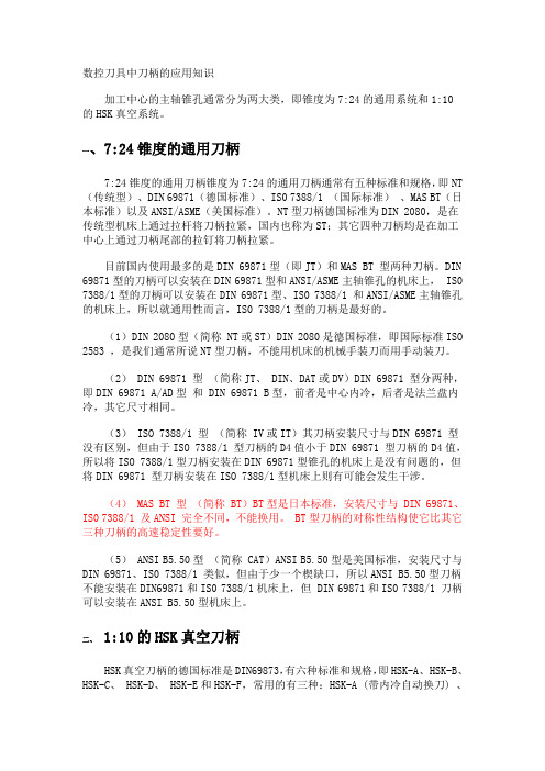
数控刀具中刀柄的应用知识加工中心的主轴锥孔通常分为两大类,即锥度为7:24的通用系统和1:10的HSK真空系统。
一、7:24锥度的通用刀柄7:24锥度的通用刀柄锥度为7:24的通用刀柄通常有五种标准和规格,即NT (传统型)、DIN 69871(德国标准)、IS0 7388/1 (国际标准)、MAS BT(日本标准)以及ANSI/ASME(美国标准)。
NT型刀柄德国标准为DIN 2080,是在传统型机床上通过拉杆将刀柄拉紧,国内也称为ST;其它四种刀柄均是在加工中心上通过刀柄尾部的拉钉将刀柄拉紧。
目前国内使用最多的是DIN 69871型(即JT)和MAS BT 型两种刀柄。
DIN 69871型的刀柄可以安装在DIN 69871型和ANSI/ASME主轴锥孔的机床上, IS0 7388/1型的刀柄可以安装在DIN 69871型、IS0 7388/1 和ANSI/ASME主轴锥孔的机床上,所以就通用性而言,IS0 7388/1型的刀柄是最好的。
(1)DIN 2080型(简称 NT或ST)DIN 2080是德国标准,即国际标准ISO 2583 ,是我们通常所说NT型刀柄,不能用机床的机械手装刀而用手动装刀。
(2) DIN 69871 型(简称JT、 DIN、DAT或DV)DIN 69871 型分两种,即DIN 69871 A/AD型和 DIN 69871 B型,前者是中心内冷,后者是法兰盘内冷,其它尺寸相同。
(3) ISO 7388/1 型(简称 IV或IT)其刀柄安装尺寸与DIN 69871 型没有区别,但由于ISO 7388/1 型刀柄的D4值小于DIN 69871 型刀柄的D4值,所以将ISO 7388/1型刀柄安装在DIN 69871型锥孔的机床上是没有问题的,但将DIN 69871 型刀柄安装在ISO 7388/1型机床上则有可能会发生干涉。
(4) MAS BT 型(简称 BT)BT型是日本标准,安装尺寸与 DIN 69871、IS0 7388/1 及ANSI 完全不同,不能换用。
Endress+Hauser Gammapilot FTG20 电气设备安全说明书

Products Solutions Services XA01138F-A/00/B2/01.1371239745Safety InstructionsGammapilotFTG20Ex d ia IIC T* GbEx d [ia] IIC T* GbGYJ13.1284XEN Document: XA01138F-ASafety instructions for electrical apparatus for explosion-hazardous areas→ 3ZH文档资料代号:XA01138F-A防爆危险区中使用的电气设备的安全指南→ 9XA01138F-A Gammapilot 2Endress+HauserGammapilot XA01138F-AEndress+Hauser3Gammapilot FTG20Associated Documentation This document is an integral part of the following Operating Instructions:BA01035F/00The Operating Instructions which are supplied and correspond to the device type apply.Supplementary Documentation Explosion-protection brochure:CP00021Z/11Designation Explanation of the labelling and type of protection can be found in the explosion protection brochure.Applied standardsDesignation of explosion protectionEx d ia IIC T*Gb Ex d [ia]IICT*Gb T* → 6GB 3836.1-2010GB 3836.2-2010GB 3836.4-2010XA01138F-A Gammapilot4Endress+HauserSafety instructions:General•Install the device according to the manufacturer's instructions and any other valid standards and regulations.•Comply with the installation and safety instructions in the Operating Instructions.•For installation, use and maintenance of the device, users must also observe the requirements stated in the Operating Instructions and the standards:–GB 50257-1996: "Code for construction and acceptance of electric device for explosion atmospheres and fire hazard electrical equipment installation engineering".–GB 3836.13-1997: "Electrical apparatus for explosive gas atmospheres, Part 13: Repair and overhaul for apparatus used in explosive gas atmospheres".–GB 3836.15-2000: "Electrical apparatus for explosive gas atmospheres, Part 15: Electrical installations in hazardous area (other than mines)".–GB 3836.16-2006: "Electrical apparatus for explosive gas atmospheres, Part 16: Inspection and maintenance of electrical installation (other than mines)".•Do not open when energized.•Do not operate the device outside the specified electrical and thermal parameters.•Changes in electrical and mechanical parts of the equipment could harm the type of explosion protection and are not allowed for the user.•To maintain the ingress protection of the housing, install the housing cover and cable glands correctly.•Close unused entry glands with sealing plugs.•Use a connecting cable for continuous duty temperature T T a +20 K.•Install the device to exclude impact and friction sparks on the aluminium housing (F13).•After aligning (rotating) the housing, retighten the fixing screw (see Operating Instructions) (for securing the earth connection).•Connect the sensor and transmitter to the common on-site potential equalization line.•Connect cable screen to earth ground at safe area.Safety instructions:Special conditions•Connecting cable between sensor and transmitter:–Do not install in the vicinity of processes generating strong electrostatic charges.–Avoid electrostatic charging of the sensor cable (e.g. do not rub dry and install outside the filling flow).–Do not leave cable hanging loosely when installed.–If the connecting cable is removed from both the sensor and the transmitter, ensure that measures are taken to avoid electrostatic discharge in a potentially explosive atmosphere.Gammapilot XA01138F-AEndress+Hauser 5Safety instructions:Installationå 1AZone 1FTG20 with electronic insert FEG24 (Relay)1Sensor 2Power supply 3Transmitter (Ex d)4Connection cable (Ex ia),Cable designation: Lapp Ölflex Heat 180 EWKF or Helu Thermflex 180 EWKF-C 5Potential equalization FTG20 with electronic insert FEG25 (8/16 mA)1Sensor 2Associated intrinsically safe apparatus [Ex ia]3Transmitter (Ex ia)4Connection cable (Ex ia),Cable designation: Lapp Ölflex Heat 180 EWKF or Helu Thermflex 180 EWKF-C 5Potential equalizationIngress protection of housing‣Transmitter, F13 housing (aluminium): IP66/67‣Transmitter, F27 housing (stainless steel): IP66/68‣Sensor (stainless steel): IP66/68XA01138F-A Gammapilot6Endress+HauserInstructions:Ex d jointsSpecification according to IEC/EN 60079-1:2007, Chapter 5.1•If required or if doubt: ask manufacturer for specifications.Safety instructions:Zone 1FTG20 with electronic insert FEG24 (Relay)•Suitable certified cable entry and blind plug approved by ExTL according to GB3836.1-2010 and GB3836.2-2010 with Ex d IIC shall be used and correctly installed.•Connect the device using suitable cable and wire entries or using piping systems of protection type "Pressure-tight Enclosure d".•Close unused entry glands with approved (Ex d) sealing plugs.The plastic sealing plug is used only as transport protection.•Transmitter housing: Do not open in a potentially explosive atmosphere.•During operation, the cover must be screwed all the way in and the cover's safety catch must be fastened.•Replace sealing plugs only with identical parts.•Lay connecting cable to the transmitter and secure.•The intrinsically safe signal circuit to the sensor is galvanically isolated from other circuits up to a peak value of the nominal voltage of 375 V.FTG20 with electronic insert FEG25 (8/16 mA)•The pertinent guidelines must be observed when intrinsically safe circuits are connected together acc. IEC 60079-14 (Proof of Intrinsic Safety).•The intrinsically safe input power circuit of the device is isolated from ground potential and has a dielectric strength of at least 500 V rms with respect to it.•The intrinsically safe signal circuit of the sensor is isolated from ground potential and has a dielectric strength of at least 500 V rms with respect to it.•When the device is connected to an intrinsically safe circuit Ex ib, the level of protection changes to Ex ib.•When the device is connected to an intrinsically safe circuit Ex ic, the level of protection changes to Ex ic. Do not operate intrinsically safe circuits Ex ic in zone 1.Temperature tablesFTG20 with electronic insert FEG24 (Relay)FTG20 with electronic insert FEG25 (8/16 mA)DesignationGammapilot FTG20Type of protection Temperature class/surface temperature/ambient temperature range Operating condition Transmitter Sensor.TransmitterSensorSensorHousingHousingSignal circuitEx d [ia] IIC T6 GbEx dEx dEx iaT6for T a = –40 °C…70 °CT6for T a = –40 °C…70 °C Without water cooling or water cooling out of operationEx d [ia] IIC T4 GbT4for T a = –40 °C…120 °CWith water cooling in operationDesignationGammapilot FTG20Type of protection Temperature class/surface temperature/ambient temperature range Operating condition Transmitter Sensor.TransmitterSensorSensorHousingHousingSignal circuitEx d ia IIC T6...T4 GbEx iaEx dEx ia T6for T a = –40 °C…40 °C T4for T a = –40 °C…70 °CT6for T a = –40 °C…70 °C Without water cooling or water cooling out of operationEx d ia IIC T4 GbT4for T a = –40 °C…120 °CWith water cooling in operationGammapilot XA01138F-A Connection data TransmitterEndress+Hauser7XA01138F-A GammapilotSensor8Endress+HauserGammapilot XA01138F-AEndress+Hauser9Gammapilot FTG20相关文档资料本文档资料是下列《操作手册》的组成部分:BA01035F各种设备须参考各自的《操作手册》。
32位微控制器 KF32F330 数据手册说明书

32位微控制器KF32F330数据手册芯片特征●CPU32位高性能KungFu32内核;工作频率最高为72MHz,可软件调节;基于16位/32位混合指令的高效指令集;3级流水线;32×32单周期乘法,32÷32硬件除法;支持中断优先级处理,实现自动中断堆栈;13个32位通用寄存器R0~R12;链接寄存器(R13);堆栈指针寄存器(R14);程序计数器(R15);24位系统节拍定时器;●存储器最高512KByte FLASH,带ECC校验;最高96KByteRAM,其中32KByte带ECC 校验;2个256Byte双端口RAM,带ECC校验;1个512Byte双端口RAM,带ECC校验;16KByte引导ROM;FLASH可经受100000次写操作;●特殊功能内嵌上电复位电路;低电压检测及低电压复位;可编程电压检测;硬件双看门狗;系统时钟6种时钟源可选;支持两线串行编程/在线调试;●I/O口配置LQFP-100封装有85个通用I/O;LQFP-64封装有53个通用I/O;LQFP-48封装有39个通用I/O;支持输入输出口设置;支持内置上拉/下拉功能;支持推挽输出和开漏输出模式;支持数字/模拟引脚设置;支持引脚功能重映射;施密特电平输入;●定时器/计数器定时器5/6/9/10为高级定时器,其中定时器5/6支持ECCP5;定时器9/10支持ECCP9定时器0/1/2/3/4/18/19/22为通用定时器,其中定时器0/1/2/3/4/18/19/22支持;CCP0/1/2/3/4/18/19/22;定时器14/15:基本定时器;定时器7/8支持QEI0/QEI1;●其它外设2个7通道DMA;1个硬件CRC32模块;4个SPI总线模块(兼容I2S);4个I2C总线模块(兼容SMBUS/PMBUS);8个USART模块(兼容7816/LIN/IRDA功能);2个CAN2.0B模块;1个USB;1个兼容8080模式的EXIC模块;1个独立的RTC(万年历);3个12位ADC模块,支持最多42个通道;2个12位DAC模块;2个CMP比较器模块;●功耗管理5种功耗模式:正常运行模式、普通休眠模式、低功耗运行模式、低功耗休眠模式、停止模式;●工作条件工作电压: 1.8V~3.6V;工作温度范围:-40~85℃(默认);*T:-40~105℃;目录芯片特征 (2)目录 (3)1芯片资源 (6)1.1产品订购信息KF32F330 (6)1.2KF32F330X QS(LQFP48) (7)1.3KF32F330X QT(LQFP64) (8)1.4F32F330X QV(LQFP100) (9)2系统概述 (10)2.1系统概述 (10)2.2指令集 (10)2.3在线编程和调试 (11)2.3.1ISP模式 (11)2.3.2DPI模式 (11)2.4系统框图 (12)2.5KF32F330外设资源对照表 (13)2.6芯片引脚图 (14)2.6.1LQFP100 (14)2.6.2LQFP64 (15)2.6.3LQFP48 (16)2.7电源引脚说明 (17)3振荡器(OSC) (18)3.1概述 (18)3.2振荡器结构框图 (19)4存储器(MEMORY) (20)4.1概述 (20)4.2存储器空间映射 (20)5I/O端口介绍 (22)5.1概述 (22)5.2引脚重映射说明(数字功能) (23)5.3引脚重映射说明(系统以及模拟功能) (27)5.4引脚重映射表-外部唤醒引脚、侵入检测和时间戳引脚映射 (31)5.5CCP引脚资源 (31)6资源介绍 (33)6.1DMA (33)6.2节拍定时器(SYSTICK) (33)6.3基本定时/计数器(T14/T15) (33)6.4通用定时/计数器(T0/1/2/3/4/18/19/22) (34)6.5高级定时/计数器(T5/T6/T9/T10) (34)6.6通用捕捉/比较/PWM模块(CCP0/1/2/3/4/18/19/22) (34)6.7增强型捕捉/比较/PWM模块(ECCP5/9) (35)6.8正交编码脉冲电路(QEI0/1) (35)6.9模数转换模块(A/D) (36)6.10数模转换器模块(D/A) (36)6.11拟比较器模块(CMP) (36)6.12通用全/半双工收发器(USART) (37)6.13串行外设接口(SPI) (37)6.14内部集成电路接口(I2C) (38)6.15EXIC接口 (38)6.16实时时钟(RTC) (38)6.17控制器局域网总线(CAN) (38)6.18独立看门狗(IWDT) (39)6.19窗口看门狗(WWDT) (39)6.20USB模块(USB) (40)6.21CFGL模块(CFGL) (40)6.22复位(RESET) (40)6.23外设模块时钟使能模块(CLK_EN) (41)6.24循环冗余校验单元(CRC) (41)7电气特性 (42)7.1概述 (42)7.1.1最大值和最小值说明 (42)7.1.2典型值 (42)7.2最大承受范围 (42)7.3运行条件 (44)7.3.1常规运行条件 (44)7.3.2上电/掉电的运行条件 (44)7.3.3复位和电源控制模块特性BOR,PVD (45)7.3.4电源电流特性 (45)7.3.5内核电源VREG (49)7.4时钟源特性 (50)7.4.1BAT PVD (50)7.4.2HSE (50)7.4.3LSE (51)7.4.4HSI (51)7.4.5LP4M (51)7.4.6LSI (52)7.4.7PLL (52)7.5EMC特性 (53)7.5.1功能性EMS(electromagnetic susceptibility) (53)7.5.1.1设计健壮的程序来规避干扰问题 (53)7.5.2电磁干扰(Electromagnetic Interference(EMI)) (54)7.6电气特性敏感度特性 (54)7.6.1静电放电特性ESD(Electrostatic discharge) (54)7.6.2静态栓锁(Static Latch-up) (54)7.7IO端口特性 (55)7.7.1静态特性 (55)7.7.2IO输出特性 (55)7.7.3IO AC特性 (55)7.7.4NRST管脚特性 (56)7.7.5外部中断特性 (56)7.8外设 (57)7.8.1ADC12BIT特性 (57)7.8.2DAC12BIT转换特性 (58)7.8.3电压参考VREFREG特性 (60)7.8.4比较器特性 (61)7.8.5USB全低速收发器模块电气特性 (61)7.9功耗特性 (62)7.9.1程序运行在FLASH时的静态功耗特性 (62)7.9.2程序运行在SRAM时的静态功耗特性 (63)7.9.3休眠功耗特性 (63)7.9.4低功耗模式特性 (63)8封装信息 (64)8.1LQFP48封装 (64)8.2LQFP64封装 (64)8.3LQFP100封装 (65)9KF32产品标识体系 (66)10ROHS认证 (67)11声明及销售网络 (68)12版本更新记录 (69)KF32F330数据手册V2.11芯旺微电子6/691芯片资源1.1产品订购信息KF32F330型号订货号封装GPIOFLASH RAM 频率16位定时器32位定时器C C PE C C PQ E IE X I CS P II 2CU S A R T低功耗U S A R TC A N低功耗C A NU S B12位A D C12位D A C运放比较器L C DR T CC F G LC R C工作电压(V )(KB )(KB)(Hz)基本通用高级低功耗KF32F330KF32F330GQS LQFP4839643272M 242N N 41X8ch 1N 223N 1N 12(22)N N 2N Y Y Y 1.8~3.6V KF32F330IQS LQFP48391283272M 242N N 41X8ch 1N 223N 1N 12(22)N N 2N Y Y Y 1.8~3.6V KF32F330IQTLQFP64531283272M 244N N 42X8ch 2N 223N 2N 12(31)2N 2N Y Y Y 1.8~3.6V KF32F330KQT LQFP64532569672M 284N N 82X8ch 2N 438N 2N 12(31)2N 2N Y Y Y 1.8~3.6V KF32F330MQT LQFP64535129672M 284N N 82X8ch 2N 438N 2N 12(31)2N 2N Y Y Y 1.8~3.6V KF32F330IQV LQFP100851283272M 244N N 42X8ch 2Y 448N 2N 13(42)2N 2N Y Y Y 1.8~3.6V KF32F330KQV LQFP100852569672M 284N N 82X8ch 2Y 448N 2N 13(42)2N 2N Y Y Y 1.8~3.6V KF32F330MQVLQFP100855129672M284NN82X8ch2Y448N2N13(42)2N2NYYY1.8~3.6VKF32F330数据手册V2.11 1.2KF32F330xQS(LQFP48)表1-1KF32F33048封装资源表型号KF32F330订货号KF32F330GQS KF32F330GQST KF32F330IQS KF32F330IQST封装LQFP48GPIO39FLASH64Kbyte,带ECC校验128Kbyte,带ECC校验RAM32Kbyte,带ECC校验ROM16Kbyte16位Timer 2个高级定时器(T5/T6),支持1个增强型ECCP5 4个通用定时器,支持4个通用CCP2个基本定时器(T14/T15)无低功耗通用定时器32位Timer NQEI112位ADC2*22DAC NCMP2USB2.0YUSART3低功耗USART NI2C2SPI2CAN2.01DMA2x7CFGL YRTC YEXIC NCRC Y内部高频振荡器16MHz内部低频振荡器32KHz外部高频时钟4~32MHz外部低频时钟32.768KHz内部参考 1.5/2/2.5/3V器件ID号含出厂版本号等指令系统V0工作电压 1.8V~3.6V工作温度-40~85℃-40~105℃-40~85℃-40~105℃KF32F330数据手册V2.11 1.3KF32F330xQT(LQFP64)表1-2KF32F33064封装资源表型号KF32F330订货号KF32F330IQT KF32F330IQTT KF32F330KQT KF32F330KQTT KF32F330MQT KF32F330MQTT 封装LQFP64GPIO53FLASH128Kbyte,带ECC校验256Kbyte,带ECC校验512Kbyte,带ECC校验RAM32Kbyte,带ECC校验96Kbyte,带ECC校验ROM16Kbyte16位Timer4个高级定时器(T5/T6/T9/T10),支持2个增强型ECCP5/ECCP9 4个通用定时器,支持4个通用CCP8个通用定时器,支持8个通用CCP2个基本定时器(T14/T15)无低功耗通用定时器32位Timer NQEI212位ADC2*31CMP2DAC22USART38低功耗USART NI2C23SPI34CAN2.02USB2.0YDMA2x7CFGL YRTC YEXIC NCRC Y内部高频振荡器16MHz内部低频振荡器32KHz外部高频时钟4~32MHz外部低频时钟32.768KHz内部参考 1.5/2/2.5/3V器件ID号含出厂版本号等指令系统V0工作电压 1.8V~3.6V工作温度-40~85℃-40~105℃-40~85℃-40~105℃-40~85℃-40~105℃KF32F330数据手册V2.11 1.4F32F330xQV(LQFP100)表1-3KF32F330100封装资源表型号KF32F330订货号KF32F330IQV KF32F330IQVT KF32F330KQV KF32F330KQVT KF32F330MQV KF32F330MQVT 封装LQFP100GPIO85FLASH128Kbyte,带ECC校验256Kbyte,带ECC校验512Kbyte,带ECC校验RAM32Kbyte,带ECC校验96Kbyte,带ECC校验ROM16Kbyte16位Timer4个高级定时器(T5/T6/T9/T10),支持2个增强型ECCP5/ECCP94个通用定时器,支持4个通用CCP8个通用定时器,支持8个通用CCP2个基本定时器(T14/T15)无低功耗通用定时器QEI212位ADC3*42CMP2DAC2USB2.0YUSART8低功耗USART NI2C4SPI4CAN2.02DMA2x7CFGL YRTC YEXIC YCRC Y内部高频振荡器16MHz内部低频振荡器32KHz外部高频时钟4~32MHz外部低频时钟32.768KHz内部参考 1.5/2/2.5/3V器件ID号含出厂版本号等指令系统V0工作电压 1.8V~3.6V工作温度-40~85℃40~105℃40~85℃40~105℃40~85℃40~105℃KF32F330数据手册V2.11 2系统概述2.1系统概述KF32F330系列单片机是基于KF32内核架构开发的单片机。
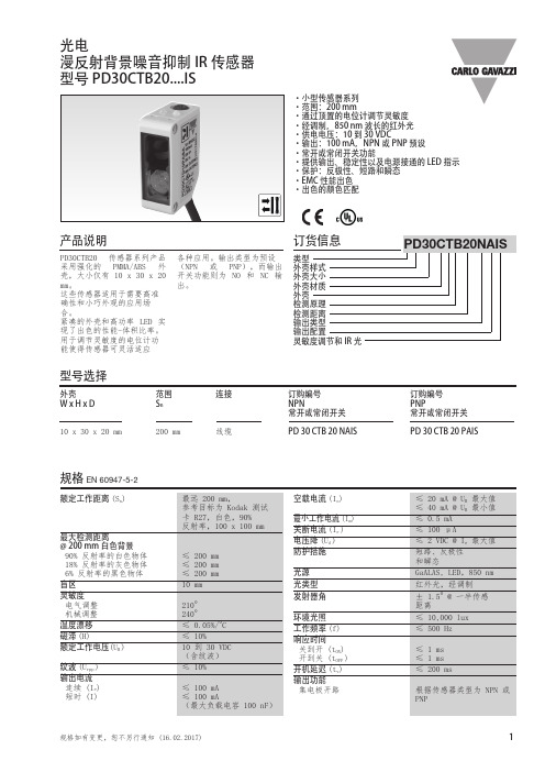
PD30CTB20红外传感器说明书
不Inc正orr确ect
正Co确rrect
> 100 mm
In不co正rrec确t
正确
Correct
P感ro应te面c保tio护n of the sensing face I不nco正rre确ct
安Se装ns在or移m动o载un体te上d 的on开a关mobile carrier
T不h能e c拉ab动le线s缆hould not be pulled
冲击
额定绝缘电压 外壳材质
机身 前玻璃 微调电容器轴
连接 线缆
重量 线缆版
CE 标志 认证
30 g / 11ms,3 正 3 负 每轴 (IEC 60068-2-6, 60068-2-32) ≤ 500 VAC (rms)
浅灰色 ABS 红色 PMMA 深灰色 POM
黑色 PVC,2 m 4 x 0.14 mm2, Ø = 3.3 mm
产品说明
订货信息
PD30CTB20 传感器系列产品 采用强化的 PMMA/ABS 外 壳,大小仅有 10 x 30 x 20 mm。 这些传感器适用于需要高准 确性和小巧外观的应用场 合。 紧凑的外壳和高功率 LED 实 现了出色的性能-体积比率。 用于调节灵敏度的电位计功 能使得传感器可灵活适应
各种应用。输出类型为预设 (NPN 或 PNP),而输出 开关功能则为 NO 和 NC 输 出。
25 50
PPoollyy. .(B黑lac色k 对on 白Wh色ite 6(%6%/9/09%0%) )
Wh白ite色ba背ckg景roun9d09%0%英[i寸nches]
3,0 3,9 4,9 5,9 6,9 7,9 8,9 9,8
75 100 125 150 175
施密特+施密特 messko zt-f2.1 变压器温度传感器 操作说明书 operating

BA2526030/03ZH-ENMESSKO® ZT-F2.1变压器温度传感器TRANSFORMER TEMPERATURE TRANSMITTER 操作说明书/ Operating Instructions目录1 安全.................................101.1 安全说明 ..............................101.2 指定应用 ..............................101.3 关于运行设备运转的重要提示.............10 2 产品规格 ..............................103 安装条件和试验........................114 表盘式温度计..........................115 组装 .................................115.1 组装 ZT-F2.1 变压器温度传感器 ............115.2安装表盘式温度计的感温包 (11)6 电气连接 ..............................126.1 连接电流互感器........................126.2 Pt100 测量电阻 .........................126.3 可选项:模拟输出端 4...20 mA ............127 设置热点梯度 .........................127.1 2 A CT 标称电流的设置 ...................12 7.2 CT 标准电流 ≠ 2 A 的设置................138 检查显示屏 ............................149 服务.................................1410 维护.................................1411 过电压保护装置 1412 技术数据 (1413)附录 (16)13.1 尺寸.................................1613.2 2 A CT 标称电流的热点梯度表 .............1713.3 更换传感器 (20)请妥善保存本手册以备将来参考!Contents1 Safety . . . . . . . . . . . . . . . . . . . . . . . . . . . . . . . . . . . .101 .1 Safety instructions . . . . . . . . . . . . . . . . . . . . . . . . .101 .2 Specified application . . . . . . . . . . . . . . . . . . . . . . . .101 .3 Important notes on equipment operation . . . . . . .10 2 Product specification . . . . . . . . . . . . . . . . . . . . . . . .103 Installation conditions and testing . . . . . . . . . . . .114 Dial-type thermometer . . . . . . . . . . . . . . . . . . . . . .115 Assembly . . . . . . . . . . . . . . . . . . . . . . . . . . . . . . . . .115 .1 Assembling the ZT-F2 .1 transformer temperaturetransmitter . . . . . . . . . . . . . . . . . . . . . . . . . . . . . . . .115 .2Installing the temperature bulb of the dial-type . . . thermometer . . . . . . . . . . . . . . . . . . . . . . . . . . . . . .116 Electrical connection . . . . . . . . . . . . . . . . . . . . . . . .126 .1 Connecting the current transformer . . . . . . . . . . .126 .2 Pt100 measuring resistor . . . . . . . . . . . . . . . . . . . .126 .3 Option: Analog output 4 . . .20 mA . . . . . . . . . . . . . .127 Setting the hot-spot gradient . . . . . . . . . . . . . . . .127 .1 Setting for 2 A CT nominal current . . . . . . . . . . . .12 7 .2 Setting for CT nominal current ≠ 2 A . . . . . . . . . .13 8Checking the display . . . . . . . . . . . . . . . . . . . . . . . .149 Service . . . . . . . . . . . . . . . . . . . . . . . . . . . . . . . . . . .1410 Maintenance . . . . . . . . . . . . . . . . . . . . . . . . . . . . . .1411 Overvoltage protection . . . . . . . . . . . . . . . . . . . . . .1412Technical data . . . . . . . . . . . . . . . . . . . . . . . . . . . . .1413 Appendix . . . . . . . . . . . . . . . . . . . . . . . . . . . . . . . .1613 .1 Dimensions . . . . . . . . . . . . . . . . . . . . . . . . . . . . . . .1613 .2 Hot-spot gradient table for 2 A CT nominalcurrent . . . . . . . . . . . . . . . . . . . . . . . . . . . . . . . . . . .1713 .3 Replacement sensor . . . . . . . . . . . . . . . . . . . . . . . .20Please keep this manual for future reference!1 安全1.1 安全说明参与本运行设备的安装、调试、运行或维护的所有人员都必须:- 具备相应的专业资格并- 严格遵守本操作说明书。
AT32F415系列微控制器数据手册说明书
基于ARM® 32位的Cortex®-M4微控制器,配有64 K字节到256 K字节闪存、sLib、11个定时器、1个ADC、2个比较器、12个通信接口(1个CAN和1个OTGFS)功能⏹内核:ARM® 32位的Cortex®-M4 CPU−最高150 MHz工作频率,带存储器保护单元(MPU)−内建单周期乘法和硬件除法−具有DSP指令集⏹存储器− 64 K字节到256 K字节的闪存存储器− 18 K字节的启动程序代码区作启动加载程序(Bootloader)用− sLib:将指定之主存储区设为执行代码安全库区,此区代码仅能调用无法读取− 32 K字节的SRAM⏹电源控制(PWC)− 2.6V至3.6V供电−上电复位(POR)、低电压复位(LVR)、电源电压监测器(PVM)−低功耗模式:睡眠、深睡眠、和待机− V BAT为LEXT、ERTC和20个32位的电池供电寄存器(BPR)供电⏹时钟和复位管理(CRM)− 4至25 MHz晶体振荡器(HEXT)−内置经出厂调校的48 MHz高速时钟(HICK),25 °C达1 %精度,-40 °C至+105 °C达2 %精度− PLL可灵活配置31到500倍频和1到15分频系数− 32 kHz晶振(LEXT)−低速内部时钟(LICK)⏹模拟模块− 1个12位2 MSPS A/D转换器,多达16个外部输入通道−温度传感器(V TS)和内部参考电压(V INTRV)− 2个比较器(CMP)⏹DMA− 2個7通道DMA控制器共14通道⏹多达55个快速GPIO端口−所有GPIO口可以映像到16个外部中断(EXINT)−几乎所有GPIO口可容忍5 V输入信号⏹多达11个定时器(TMR)− 1个16位7通道高级定时器,包括3对互补通道PWM输出,带死区控制和紧急停止功能−多达5个16位定时器和2个32位定时器,每个定时器最多达4个用于输入捕获/输出比较/PWM或脉冲计数的通道和增量编码器输入− 2个看门狗定时器(一般型WDT和窗口型WWDT)−系统滴答定时器:24位递减计数器⏹ERTC:增强型RTC,具有自动唤醒、闹钟、亚秒级精度、及硬件日历,带校准功能⏹多达12个通信接口− 2个I2C接口,支持SMBus/PMBus− 5个USART接口;支持主同步SPI和调制解调器控制;具有ISO7816接口、LIN和IrDA− 2个SPI接口(36 M位/秒),均可复用为半双工I2S接口− CAN接口(2.0B主动),内置256字节的专用缓存− OTGFS全速控制器含片上PHY,内置1280字节的专用缓存− SDIO接口⏹CRC计算单元⏹96位的芯片唯一代码(UID)⏹调试模式−串行线调试(SWD)和JTAG接口⏹温度范围:-40至+105 °C封装Array− LQFP64 10 x 10 mm− LQFP64 7 x 7 mm− LQFP48 7 x 7 mm− QFN48 6 x 6 mm− QFN32 4 x 4 mm目录1规格说明 (11)2功能简介 (13)2.1ARM®Cortex®-M4 (13)2.2存储器 (14)2.2.1闪存存储器(Flash) (14)2.2.2存储器保护单元(MPU) (14)2.2.3内置随机存取存储器(SRAM) (14)2.3中断 (14)2.3.1嵌套的向量式中断控制器(NVIC) (14)2.3.2外部中断(EXINT) (14)2.4电源控制(PWC) (14)2.4.1供电方案 (14)2.4.2复位和电源电压监测器(POR / LVR / PVM) (15)2.4.3电压调节器(LDO) (15)2.4.4低功耗模式 (15)2.5启动模式 (15)2.6时钟 (16)2.7通用输入输出口(GPIO) (16)2.8重映射功能 (16)2.9直接存储器访问控制器(DMA) (16)2.10定时器(TMR) (17)2.10.1高级定时器(TMR1) (17)2.10.2通用定时器(TMR2~5和TMR9~11) (17)2.10.3系统滴答定时器(SysTick) (18)2.11看门狗(WDT) (18)2.12窗口型看门狗(WWDT) (18)2.13增强型实时时钟(ERTC)和电池供电寄存器(BPR) (18)2.14通信接口 (19)2.14.1串行外设接口(SPI) (19)2.14.2内部集成音频接口(I2S) (19)2.14.3通用同步/异步收发器(USART) (19)2.14.4内部集成电路总线(I2C) (19)2.14.5安全数字输入/输出接口(SDIO) (19)2.14.6控制器区域网络(CAN) (20)2.14.7通用串行总线On-The-Go全速(OTGFS) (20)2.15循环冗余校验(CRC)计算单元 (20)2.16模拟/数字转换器(ADC) (20)2.16.1温度传感器(V TS) (20)2.16.2内部参考电压(V INTRV) (21)2.17比较器(CMP) (21)2.18调试:串行线(SWD)/ JTAG调试接口 (21)3引脚定义 (22)4存储器映像 (28)5电气特性 (29)5.1测试条件 (29)5.1.1最小和最大数值 (29)5.1.2典型数值 (29)5.1.3典型曲线 (29)5.1.4供电方案 (29)5.2绝对最大值 (30)5.2.1额定值 (30)5.2.2电气敏感性 (31)5.3规格 (32)5.3.1通用工作条件 (32)5.3.2上电和掉电时的工作条件 (32)5.3.3内嵌复位和电源控制模块特性 (32)5.3.4存储器特性 (34)5.3.5供电电流特性 (34)5.3.6外部时钟源特性 (42)5.3.7内部时钟源特性 (46)5.3.8PLL特性 (47)5.3.9低功耗模式唤醒时间 (47)5.3.10EMC特性 (47)5.3.11GPIO端口特性 (48)5.3.12NRST引脚特性 (50)5.3.13TMR定时器特性 (50)5.3.14SPI接口特性 (51)5.3.15I2S接口特性 (53)5.3.16I2C接口特性 (54)5.3.17SDIO接口特性 (55)5.3.18OTGFS接口特性 (56)5.3.1912位ADC特性 (57)5.3.20内部参照电压(V INTRV)特性 (59)5.3.21温度传感器(V TS)特性 (60)5.3.22比较器(CMP)特性 (61)6封装特性 (62)6.1LQFP64 – 10 x 10 mm封装数据 (62)6.2LQFP64 – 7 x 7 mm封装数据 (64)6.3LQFP48 – 7 x 7 mm封装数据 (66)6.4QFN48 – 6 x 6 mm封装数据 (68)6.5QFN32 – 4 x 4 mm封装数据 (70)6.6封装丝印 (71)6.7热特性 (72)7型号说明 (73)8版本历史 (74)表目录表1. 选型列表 (2)表2. AT32F415系列器件功能和配置 (12)表3. 启动加载程序(Bootloader)的管脚配置 (16)表4. 定时器功能比较 (17)表5. AT32F415系列引脚定义 (25)表6. 电压特性 (30)表7. 电流特性 (30)表8. 温度特性 (30)表9. ESD值 (31)表10. Latch-up值 (31)表11. 通用工作条件 (32)表12. 上电和掉电时的工作条件 (32)表13. 内嵌复位和电源管理模块特性 (32)表14. 可编程电压检测器特性 (33)表15. 内部闪存存储器特性 (34)表16. 内部闪存存储器寿命和数据保存期限 (34)表17. 运行模式下的典型电流消耗 (35)表18. 睡眠模式下的典型电流消耗 (36)表19. 运行模式下的最大电流消耗 (37)表20. 睡眠模式下的最大电流消耗 (37)表21. 深睡眠和待机模式下的典型和最大电流消耗 (38)表22. V BAT的典型和最大电流消耗(LEXT和ERTC开启) (40)表23. 内置外设的电流消耗 (41)表24. HEXT 4 ~ 25 MHz晶振特性 (42)表25. 高速外部用户时钟特性 (43)表26. LEXT 32.768 kHz晶振特性 (44)表27. 低速外部用户时钟特性 (45)表28. HICK振荡器特性 (46)表29. LICK振荡器特性 (46)表30. PLL特性 (47)表31. 低功耗模式的唤醒时间 (47)表32. EMS特性 (47)表33. GPIO静态特性 (48)表34. 输出电压特性 (49)表35. 输入交流特性 (49)表36. NRST引脚特性 (50)表37. TMR定时器特性 (50)表38. SPI特性 (51)表39. I2S特性 (53)表40. SD/MMC接口特性 (55)表41. OTGFS启动时间 (56)表42. OTGFS直流特性 (56)表43. OTGFS电气特性 (56)表44. ADC特性 (57)表45. f ADC = 14MHz时的最大R AIN (58)表46. f ADC = 28MHz时的最大R AIN (58)表47. ADC精度 (58)表48. 内置参照电压特性 (59)表49. 温度传感器特性 (60)表50. 比较器特性 (61)表51. LQFP64 – 10 x 10 mm 64引脚薄型正方扁平封装机械数据 (63)表52. LQFP64 – 7 x 7 mm 64引脚薄型正方扁平封装机械数据 (65)表53. LQFP48 – 7 x 7 mm 48引脚薄型正方扁平封装机械数据 (67)表54. QFN48 – 6 x 6 mm 48引脚正方扁平无引线封装机械数据 (69)表55. QFN32 – 4 x 4 mm 32引脚正方扁平无引线封装机械数据 (71)表56. 封装的热特性 (72)表57. AT32F415系列型号说明 (73)表58. 文档版本历史 (74)图目录图1. AT32F415系列功能框图 (13)图2. AT32F415系列LQFP64引脚分布 (22)图3. AT32F415系列LQFP48引脚分布 (23)图4. AT32F415系列QFN48引脚分布 (23)图5. AT32F415系列QFN32引脚分布 (24)图6. 存储器图 (28)图7. 供电方案 (29)图8. 上电复位和掉电复位波形图 (33)图9. LDO在运行模式时,深睡眠模式下的典型电流消耗在不同的V DD时与温度的对比 (38)图10. LDO在低功耗模式时,深睡眠模式下的典型电流消耗在不同的V DD时与温度的对比 (39)图11. 待机模式下的典型电流消耗在不同的V DD时与温度的对比 (39)图12.V BAT的典型电流消耗(LEXT和RTC开启)在不同的V BAT电压时与温度的对比 (40)图13. 使用8 MHz晶体的典型应用 (42)图14. 外部高速时钟源的交流时序图 (43)图15. 使用32.768 kHz晶体的典型应用 (44)图16. 外部低速时钟源的交流时序图 (45)图17. HICK时钟精度与温度的对比 (46)图18. 建议的NRST引脚保护 (50)图19. SPI时序图– 从模式和CPHA = 0 (52)图20. SPI时序图– 从模式和CPHA = 1 (52)图21. SPI时序图–主模式 (52)图22. I2S从模式时序图(Philips协议) (53)图23. I2S主模式时序图(Philips协议) (54)图24. SDIO高速模式 (55)图25. SD默认模式 (55)图26. OTGFS时序:数据信号上升和下降时间定义 (56)图27. ADC精度特性 (59)图28. 使用ADC典型的连接图 (59)图29. V TS对温度理想曲线图 (60)图30. 比较器迟滞图 (61)图31. LQFP64 – 10 x 10 mm 64引脚薄型正方扁平封装图 (62)图32. LQFP64 – 7 x 7 mm 64引脚薄型正方扁平封装图 (64)图33. LQFP48 – 7 x 7 mm 48引脚薄型正方扁平封装图 (66)图34. QFN48 – 6 x 6 mm 48引脚正方扁平无引线封装图 (68)图35. QFN32 – 4 x 4 mm 32引脚正方扁平无引线封装图 (70)图36. 丝印示意图 (71)1 规格说明AT32F415系列微控制器基于高性能的ARM®Cortex®-M4 32位的RISC内核,最高工作频率达到150MHz,Cortex®-M4内核具有一组DSP指令和提高应用安全性的一个存储器保护单元(MPU)。
库存详单
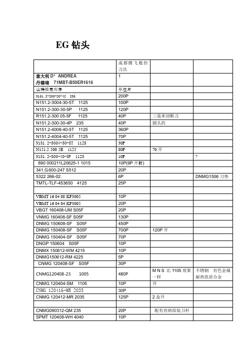
410P 79P 9P 20P 30P 21P 160P 8P 20P 100P 14P
.1
A4G0500M05P08GMP KC5025 A3G0500M05P08DF KC5025
.4
NG3M250LK KC5025 NG2094R K68 NR3062RK KC730 NR3047R K68 NRP3047R KC730 NG2031L KC850 NJP3014R12 KC730 DWG 165081R04 KC5025 NT1L KC5025 DNGP150408 KC7310 DNGP150404 KC7310 10P 9P 10P 20P 5P 10P 9P 400P 400P
4P 30P
螺纹刀片 螺纹刀片
DNMG150404FN KC9215
10P
DNMG150608MS KC5510 DNMG150408MS KC5510 DNMG150404MS KC5510 CNMG120408MS KC5510 CNMG120404MS KC5510 CNMG120402MS KC5510 CNMG120408UP KCU10 CNMG120412UP KCU10 CNMG120412RP KC5525 CNMG120408MN KCP10 CNMG120408MPI KC5010 CNMG120412MPI KC5010 SNMG120408MS KC5510 CNGP120408 KC7310 CNMG120412P KC935
特维克切槽刀杆
RF151.23-3225-40M1 毫米切刀刀杆 LF151.23-3225-40M1 米切刀刀杆 RF151.23-3225-30M1 毫米切刀刀杆 LF123H25-3225BM 全新原装
AHTT2820高精密温湿度传感器产品说明书
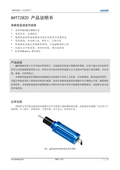
AHTT2820产品说明书高精密温湿度传感器•光学冷镜式露点测量方式•重复性好,长期稳定•精准的温度和湿度测量及提供各种相关参数转化•高度集成,供电5V/1A,体积小,方便应用•转换器连电脑记录数据和曲线,可选ACM483T主机•结露自动平衡系统、预热时间短、响应速度快•标准的Modbus RTU通信产品综述AHTT2820是基于光学冷镜式原理设计,对温湿度直接进行测量的传感器。
区别于通过电容电阻变化等方式间接测量湿度的方法,利用光学冷镜式原理依据露点定义直接对环境进行湿度测量,具有直观、准确、可靠等特点。
本高精密温湿度传感器的结露镜面经过特殊的半导体工艺处理,具有耐腐蚀、耐高低温等特性,且露点和温度采用了精密铂电阻进行测量,因而本高精密温湿度传感器具有长期稳定可靠、测量精度高等特性。
本高精密温湿度传感器既能在多数应用环境中使用并能确保高测量精度,还能满足部分恶劣环境需求。
应用范围高精密光学冷镜式温湿度传感器可以作为湿度计量检测标准仪器。
此温湿度传感器广泛应用于计量检测、军工航空、高校科研、气象环境、电子电力、医药等行业。
图1.AHTT2820高精密温湿度传感器1.传感器原理露点是指水或冰汽化成气态的最大程度(即饱和水汽压)时所对应的温度。
通常气体中实际水汽压在环境温度降到该水汽压对应的露点温度以下时,水汽会凝结成露或霜。
相对湿度是指在一定温度下,实际水汽含量(水汽压)与该温度下理论饱和水汽含量(水汽压)之比。
冷镜式露点系统是利用半导体制冷片控制镜面温度变化,当含水汽的气体通过镜面时,水汽在镜面表面出现结露或结霜,再经过检测结露或结霜的厚度进行自动调节镜面温度,直到结露或结霜的厚度稳定,从而检测出镜面结露或结霜稳定后的温度的智能系统。
冷镜式露点系统是利用半导体制冷片控制镜面温度变化检测出镜面结露或结霜稳定后的温度的智能系统。
当含水汽的气体通过镜面时,在镜面表面出现结露或结霜。
经过检测结露或结霜的厚度进行自动调节镜面温度,直到结露或结霜的厚度稳定在系统的设定值。
【优质】Thermo Form 311 CO2培养箱中文说明书

型号310系列二氧化碳培养箱操作及维护指南手册号:7010310 第一版所有型号参阅第i页手册号 7010310- 22434/IN-3211 8/25/04 更新增湿盘水质量描述 CCS1 21730/SI-9181 6/16/04 添加可调换的250085底座 CCS0 22078/IN-3180 3/16/04 原始手册-将156098型号的风机发动机更新为156126型号。
CCSREV ECR/ECN DATE DESCRIPTION By仔细阅读本指南如未阅读,理解,遵循本指南将导致设备受损,人员受到伤害和设备的低效运行。
注意:所有的调节和维修工作必须由合格的专业人员操作。
参见本手册后的型号标签*T/C是热导传感器IR是红外传感器**所有单位是50/60HZ内部材料为铜产品性能可能发生变化。
热电公司对该指南本身不作保证。
如因使用指南不当或与指南相关的问题造成直接或偶然的损失,本公司不负有任何责任。
如不按照操作指南进行操作,该设备所设计的保护将遭到破警告:设备和配件很容易因其释放的静电(ESD)而受损重要的操作和维护说明,请仔细阅读所附正文。
感叹号后边那部分是法语,我翻不了……用电的潜在危险,只有合格的工作人员才能进行操作。
感叹号后边那部分是法语,我翻不了……√使用适当的保护设备(工作服,手套,护目镜等等)√避免空气过热或过冷,并且需穿防护衣。
√有良好的卫生习惯。
√每个工作人员都要对自己的安全负责。
关于热电集团的产品,您是否需要更多的信息或者帮助?如果需要,请按以下方式在8:00到18:00(东部时间)联系我们:直拨:1-740-373-4763免费电话(美国和加拿大):1-888-213-1790传真:1-740-373-4189网址:服务邮箱地址:services.controlenvce.@我们的销售人员可为您提供价格信息和报价表。
我们可按照订单为您提供主要的仪器交付条款信息或安排当地的销售代表联系您。
新普特温度控制器产品说明书
I8C00-C24I8C001Ordering Examples: i8C33, 1⁄8 DIN compact universal temperature process controller with 2 relay outputs.*2 Analog output is not available with “-AL ” units.*3 “-SM ” option not available on iSstrain models.1⁄8 DIN Ultra Compact Case, Temperature, Process and Strain PID Controllersi8C Seriesi8C33 shown smaller than actual size.The ultra-compact i8C and iS8C controllers are similar to the full size i8 in an ultra-compact enclosure. Only 51 mm (2") behind the panel.U Ultra Compact 1⁄8 DIN Controller U Full Autotune PID Control U Built-In Excitation U NEMA 4 (IP65) BezelU RS232, RS422/485 or Modbus Communication, Menu Selectable2Universal Temperature and Process Input ("i" Models)Accuracy: ±0.5°C temp; 0.03% rdg Resolution: 1°/0.1°; 10 μV process Temperature Stability: RTD: 0.04°C/°CTC @ 25°C (77°F): 0.05°C/°C Cold Junction Compensation Process: 50 ppm/°C NMRR: 60 dB CMRR: 120 dBA/D Conversion: Dual slope Reading Rate: 3 samples/s Digital Filter: Programmable Display: 4-digit 9-segment LED 10.2 mm (0.40"); i32, i16, i16D, i8DV 21 mm (0.83"); i8 10.2 mm (0.40") and 21 mm (0.83"); i8DH RED , GREEN , and AMBER programmable colors for process variable, setpoint and temperature unitsInput Types: Thermocouple, RTD, analog voltage, analog currentThermocouple Lead Resistance: 100 Ω maxThermocouple Types (ITS 90): J, K, T, E, R, S, B, C, N, L (J DIN)RTD Input (ITS 68): 100/500/1000 Ω Pt sensor, 2-, 3- or 4-wire; 0.00385 or 0.00392 curveVoltage Input: 0 to 100 mV, 0 to 1V, 0 to 10 VdcInput Impedance: 10 M Ω for 100 mV 1 M Ω for 1 or 10 VdcCurrent Input: 0 to 20 mA (5 Ω load)Configuration: Single-ended Polarity: UnipolarStep Response: 0.7 sec for 99.9%Decimal Selection: Temperature: None, 0.1 Process: None, 0.1, 0.01 or 0.001Setpoint Adjustment: -1999 to 9999 counts Span Adjustment: 0.001 to 9999 countsOffset Adjustment: -1999 to 9999Excitation (Not Included withCommunication): 24 Vdc @ 25 mA (not available for low-power option)Universal Strain and Process Input ("iS" Models)Accuracy: 0.03% reading Resolution: 10/1μVTemperature Stability: 50 ppm/°C NMRR: 60 dB CMRR: 120 dBA/D Conversion: Dual slope Reading Rate: 3 samples/s Digital Filter: ProgrammableInput Types: Analog voltage and current Voltage Input: 0 to 100 mVdc, -100 mVdc to 1 Vdc, 0 to 10 VdcInput Impedance: 10 M Ω for 100 mV; 1 M Ω for 1V or 10 VdcCurrent Input: 0 to 20 mA (5 Ω load)Linearization Points: Up to 10Configuration: Single-ended Polarity: UnipolarStep Response: 0.7 sec for 99.9%Decimal Selection: None, 0.1, 0.01 or 0.001Setpoint Adjustment: -1999 to 9999 countsSpan Adjustment: 0.001 to 9999 counts Offset Adjustment: -1999 to 9999Excitation (Optional In Place Of Communication): 5 Vdc @ 40 mA; 10 Vdc @ 60 mAControlAction: Reverse (heat) or direct (cool)Modes: Time and amplitude proportional control; selectable manual or auto PID, proportional, proportional with integral, proportional with derivative and anti-reset Windup, and on/off Rate: 0 to 399.9 s Reset: 0 to 3999 sCycle Time: 1 to 199 s; set to 0 for on/off Gain: 0.5 to 100% of span; setpoints 1 or 2Damping: 0000 to 0008Soak: 00.00 to 99.59 (HH:MM), or OFF Ramp to Setpoint:00.00 to 99.59 (HH:MM), or OFF Auto Tune: Operator initiated from front panelControl Output 1 and 2Relay: 250 Vac or 30 Vdc @ 3 A (resistive load); configurable for on/off, PID and ramp and soakOutput 1: SPDT, can be configured as alarm 1 outputOutput 2: SPDT, can be configured as alarm 2 outputSSR: ******************.5A (resistive load); continuousDC Pulse: Non-isolated; 10 Vdc @ 20 mA Analog Output (Output 1 Only):Non-isolated, proportional 0 to 10 Vdc or 0 to 20 mA; 500 Ω maxOutput 3 Retransmission:Isolated Analog Voltage and Current Current: 10 V max @ 20 mA output Voltage: 20 mA max for 0 to 10 V output Network and CommunicationsEthernet: Standards compliance IEEE 802.3 10 Base-T Supported Protocols: TCP/IP, ARP, HTTPGETRS232/RS422/RS485: Selectable from menu; both ASCII and Modbus protocol selectable from menu; programmable 300 to 19.2 Kb; complete programmable setup capability; program to transmit current display, alarm status, min/max, actual measured input value and statusCommon Specifications(All i/8, i/16, i/32 DIN)RS485: Addressable from 0 to 199 Connection: Screw terminalsAlarm 1 and 2 (Programmable)Type: Same as output 1 and 2Operation: High/low, above/below, band, latch/unlatch, normally open/ normally closed and process/deviation; front panel configurationsAnalog Output (Programmable):Non-isolated, retransmission 0 to 10 Vdc or 0 to 20 mA, 500 Ω max (output 1 only); accuracy is ±1% of FS when following conditions are satisfied: input is not scaled below 1% of input FS, analog output is not scaled below 3% of output FSGeneralPower: 90 to 240 Vac ±10%, 50 to 400Hz*, 110 to 375 Vdc, equivalent voltageLow Voltage Power Option: 24 Vac**, 12 to 36 Vdc for i/iS; 20 to 36 Vdc for dual display, ethernet, and isolated analog output from qualified safety approved source IsolationPower to Input/Output: 2300 Vac per 1 minute testFor Low Voltage Power Option: 1500 Vac per 1 minute test Power to Relay/SSR Output: 2300 Vac per 1 minute testRelay/SSR to Relay/SSR Output: 2300 Vac per 1 minute test RS232/485 to Input/Output: 500 Vac per 1 minute test Environmental Conditions:All Models: 0 to 55°C (32 to 131°F) 90% RH non-condensing Dual Display Models:0 to 50°C (32 to 122°F), 90% RH non-condensing (for UL only)Protection:i/iS32, 16, 16D, 8C:NEMA 4X/Type 4 (IP65) front bezel i/iS8, 8DH, 8DV:NEMA 1/Type 1 front bezel Approvals: UL, C-UL, CE perEN61010- 1:2001, FM (temperature units only)Dimensionsi/8 Series: 48 H x 96 W x 127 mm D (1.89 x 3.78 x 5")i/16 Series: 48 H x 48 W x 127 mm D (1.89 x 1.89 x 5")i/32 Series: 25.4 H x 48 W x 127 mm D (1.0 x 1.89 x 5")Panel Cutouti/8 Series: 45 H x 92 mm W (1.772 x 3.622"), 1⁄8 DINi/16 Series: 45 mm (1.772") square, 1⁄16 DINi/32 Series: 22.5 H x 45 mm W (0.886 x 1.772"), 1⁄32 DIN Weighti/8 Series: 295 g (0.65 lb) i/16 Series: 159 g (0.35 lb) i/32 Series: 127 g (0.28 lb)* No CE compliance above 60 Hz.** Units can be powered safely with 24 Vacpower, but no certification for CE/UL are claimed.I8C00-C24I8C00。
FLIR T630sc蜂窝热成像摄像头说明书
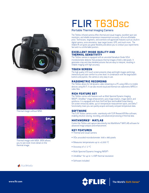
FLIR T630scPortable Thermal Imaging CameraThe T630sc infrared camera offers thermal and visual imagery, excellent spot size resolution, and reliable temperature measurement accuracy—all at an affordableprice. Technicians, engineers, and scientists will appreciate features such as a built-in digital camera, voice annotation, laser target locator, GPS, and much more. The tiltable IR unit gives you great flexibility and allows you to conduct your experiments fast and in a comfortable position.EXCELLENT IMAGE QUALITY AND THERMAL SENSITIVITYThe T630sc camera is equipped with an uncooled Vanadium Oxide (VOx) microbolometer detector that produces thermal images of 640 x 480 pixels. It generates crisp and clear detailed pictures that are easy to interpret, resulting in reliable imaging with high accuracy.TOUCH SCREENThe high quality LCD touch screen presents sharp and bright images and brings interactivity and user comfort to a new level. In combination with the large backlit buttons and joystick, the camera is very easy to use.RADIOMETRIC RECORDINGThe T630sc allows for full dynamic video streaming to a PC using USB or to mobile devices using Wi-Fi. It can also record visual and thermal non-radiometric MPEG-4 video files.RICH FEATURE SETThe T630sc comes with features such as Multi Spectral Dynamic Imaging(MSX ®), UltraMax ™ image enhancement, auto-image rotation, image sketch, and autofocus. It is equipped with Auto Hot/Cold Spot and Audible/Visual Alarms. On-screen emissivity tables, up to 5 temperature measurement spots, and Delta T functionality mean you can quickly acquire and easily compare temperature data.SOFTWAREThe FLIR T630sc camera works seamlessly with FLIR ResearchIR Max software, enabling intuitive viewing, recording, and advanced processing of thermal data.MATHWORKS® MATLAB Control the T630sc and capture data directly into MathWorks ® MATLAB software for advanced image analysis and enhancement.KEY FEATURES• Thermal and visual camera• VOx uncooled microbolometer: 640 x 480 pixels• Measures temperatures up to +2,000 °C • Accuracy of +/- 2 °C• Multi Spectral Dynamic Imaging (MSX ®)• UltraMax ™ for up to 1.2 MP thermal resolution • Software includedThermal image with MSX. MSX allows you to see even more detail on the thermal image.Thermal image without MSX.Specifications/research NASDAQ: FLIRSpecifications are subject to change without notice©Copyright 2016, FLIR Systems, Inc. All other brand and product names are trademarks of their respective owners. The images displayed may not be representative of the actual resolution of the camera shown. Images for illustrative purposes only. (Updated 01/06/16)NASHUAFLIR Systems, Inc.9 Townsend West Nashua, NH 06063USAPH: +1 866.477.3687UKFLIR Systems UK 2 Kings Hill Avenue Kings HillWest Malling - Kent ME19 4AQUnited KingdomPH: +44 (0)1732 220 011LATIN AMERICAFLIR Systems BrasilAv. Antonio Bardella, 320Sorocaba, SP 18052-852BrasilTEL: +55 15 3238 7080SWEDENFLIR Systems AB Antennvägen 6, PO Box 7376SE-187 66 Täby SwedenPH: +46 (0)8 753 25 00HONG KONGFLIR Systems Co., Ltd Rm 1613-16, Tower II Grand Central Plaza 138 Shatin RuralCommittee Road Shatin,New Territories Hong KongTEL: +852 2792 8955CANADAFLIR Systems, Ltd.920 Sheldon CourtBurlington, ON L7L 5L6CanadaPH: +1 800.613.0507EUROPEFLIR SystemsLuxemburgstraat 22321 Meer BelgiumPH: +32 (0) 3665 5100PORTLANDCorporate Headquarters FLIR Systems, Inc.27700 SW Parkway Ave.Wilsonville, OR 97070USAPH: +1 866.477.3687。
TQ30F用户手册

目 录1.适用范围12.产品概述13.正常工作条件34.产品型号及含义35.产品规格及技术参数46.控制方式57.显示78.控制器面板说明99.安装与调试1110.使用和维护 1511.保修期与售后服务1721企业简介天津市百利电气有限公司是按现代企业制度组建的全新企业,是上市公司--天津百利特精电气股份有限公司的全资子公司(股票简称:百利电气,股票代码:600468)。
公司有生产塑壳式断路器(MCCB)、万能式断路器(ACB)的悠久历史,其主导产品为:低压电器元件、电气传动及成套装置等。
拥有15大系列、上万种规格。
新建占地12万平方米的现代化工厂坐落于天津西青经济开发区。
企业高层管理者由博士、硕士等一批高级专业人员组成,并且拥有一支经验丰富、素质精良的员工队伍。
由电气行业专家和具有大学本科以上学历的电气专业技术人员组成的公司技术中心被天津市政府授予市级企业技术中心称号。
公司以高科技为先导,引进国内外先进的计算机软件及加工设备,广泛采用CAD、CAM进行设计、生产并实行ERP管理。
领先国际推出的TM30系列塑壳式断路器,具有体积小、零飞弧、智能化、分断能力高等特点。
近年,研发并投放市场的TM40系列产品,除具有TM30产品特点外,还具有隔离功能、模块化及所有附件均为插接式等特点,更便于用户使用及安装;TW30系列智能型万能式断路器最大壳架电流达到6300安培,是目前国22内乃至世界最大的壳架电流等级;TQ30V(D)系列自动转换开关是TQ30P系列自动转换开关的换代产品,额定电流从1A至6300A,是目前国内最大的自动转换开关系列;TQ40P系列自动转换开关、TJ40系列交流接触器和TM31系列微型断路器等其性能指标已达到国际先进水平;TW40系列万能式断路器的极限分断能力为国际领先水平。
上述新产品,分别荣获国家级新产品奖、天津市技术创新优秀项目奖,累计获得14项国家授权专利。
公司质量管理体系取得ISO9001认证。
工业CFast卡F-50系列SATA III-6.0 Gbit s标准和工业温度等级数据表说明书
SFCA032GH1AD4TOIGS 216STD SFCA064GH1AD4TOIGS216STDSFCA128GH1AD4TOILT216STDSFCA256GH1AD4TOIHT216STDContents1.PRODUCT SUMMARY (3)2.PRODUCT FEATURES (4)3.ORDERING INFORMATION (5)4.PRODUCT DESCRIPTION (6)4.1P ERFORMANCE S PECIFICATIONS (7)4.2C URRENT C ONSUMPTION (7)4.3E NVIRONMENTAL S PECIFICATIONS (8)4.4R EGULATORY C OMPLIANCE (9)4.5M ECHANICAL S PECIFICATIONS (9)4.6R ELIABILITY AND E NDURANCE (10)4.7D RIVE G EOMETRY S PECIFICATION (10)5.ELECTRICAL INTERFACE (11)6.PACKAGE MECHANICAL (12)7.ATA COMMANDS (13)8.IDENTIFY DEVICE DATA (15)9.S.M.A.R.T. FUNCTIONALITY (16)9.1S.M.A.R.T.S UBCOMMANDS (16)9.2S.M.A.R.T.R EAD D ATA (17)9.3S.M.A.R.T.A TTRIBUTES (17)9.4S.M.A.R.T.A TTRIBUTE E NTRY S TRUCTURE (18)10.PART NUMBER DECODER (19)10.1M ANUFACTURER (19)10.2M EMORY T YPE (19)10.3P RODUCT T YPE (19)10.4D ENSITY (19)10.5P LATFORM (19)10.6P RODUCT G ENERATION (19)10.7M EMORY O RGANIZATION (19)10.8T ECHNOLOGY (19)10.9N UMBER OF F LASH C HIPS (19)10.10F LASH C ODE (20)10.11T EMPERATURE O PTION (20)10.12D IE C LASSIFICATION (20)10.13P IN M ODE (20)10.14D RIVE C ONFIGURATION XYZ (20)10.15O PTION (20)11.SWISSBIT CFAST SSD MARKING SPECIFICATION (21)11.1T OP V IEW (21)11.2B OTTOM V IEW (21)11.3L ABEL C ONTENT (21)12.REVISION HISTORY (22)F-50 Series – Industrial CFast™Solid State Drive8 GBytes Up to 256 GBytes1.Product Summary∙Capacities: 8 GBytes, 16 GBytes, 32 GBytes, 64 GBytes, 128 GBytes, 256 GBytes∙Form Factor: CFast-Sized Solid State Drive (36.4 mm x 42.8 mm x 3.6 mm)∙Compliance: SATA Rev 3.1 - 6 Gbit/s (3 Gbit/s and 1.5 Gbit/s backward compatible)∙CFast 2.0 Compatible1∙Command Sets: Supports ATA/ATAPI-8 and ACS-2∙Performance:o Burst Transfer Rate: Up to 600 MBytes/s in SATA III - 6.0 Gbit/so Read Performance: Sequential Read up to 500 MBytes/s, Random Read IOPs up to 53Ko Write Performance: Sequential Write up to 330 MBytes/s, Random Write IOPs up to 74K ∙Operating Temperature Range2:o Commercial: 0 °C to 70 °Co Industrial: -40 °C to 85 °C∙Storage Temperature Range: -40 °C to 85 °C∙Operating Voltage: 3.3 V ± 5%∙Power (Max Capacity):o Read (Active): 1.2 Wo Write (Active): 2.0 Wo Idle: 248 mWo Slumber: 17 mW∙Data Retention: 10Years @ Life Begin; 1 Year @ Life End∙Endurance: TeraBytes Written (TBW) @ Max Capacity3o Client > 155o Enterprise > 5∙Shock/Vibration: 500 g/20 g (MIL-STD810)∙High-Performance 32-Bit Processor with Integrated, Parallel Flash Interface Engines: o Multi-Level Cell (MLC) NAND Flasho Hardware BCH Code ECC (up to 66 bit correction per 1 KByte page)∙High Reliability:o Mean Time Between Failure (MTBF): > 2,000,000 hourso Data Reliability: < 1 non-recoverable error per 1016 bits read1Devices are CFast 2.0 compatible when in removable mode. Devices in removable mode are available upon request.2Adequate airflow is required to ensure the drive temperature, as reported in the S.M.A.R.T. data, does not exceed the specified maximum operating temperature.3According to JEDEC, the time to write the full TBW is a minimum of 18 months. Higher average daily data volume reduces the specified TBW.2.Product Features∙Dynamic and Static Wear Leveling∙Page Mode Flash Translation Layer (FTL)∙Data Care Managemento Active: Adaptive Read Refresho Passive: Background Media Scan∙Lifetime Enhancementso Dynamic Bad Block Remappingo Write Amplification Reduction∙On-Board Power Fail Protection∙AHCI, TRIM, and NCQ Support∙ATA Security Feature Set Support∙DEVSLP Compatible∙In-Field Firmware Update∙Self-Monitoring, Analysis, and Reporting Technology (S.M.A.R.T.)∙Life Cycle Management∙Controlled “Locked” BOM∙RoHS-6 Compliant∙30 µinch Gold-Plated Connector (on request)∙Conformal coating (on request)∙Swissbit Life Time Monitoring (SBLTM) Tool and SDK for SBLTM (on request)3.Ordering Information4.Product DescriptionThe Swissbit® F-50 Solid State Drive (SSD) leverages the CFast 2.0 compatible, industry-standard form factor and connectivity. Combined with a SATA Gen III controller and Multi-Level Cell (MLC) NAND flash technology, the F-50 realizes a robust non-volatile storage solution for today’s embedded storage applications. A functional block diagram of the F-50 SSD is provided below in Figure 1.Figure 1: F-50 CFast Functional Block DiagramThe F-50 SSD incorporates two existing industry standards into a single product: the CompactFlash™ (CF) card form factor and the Serial ATA (SATA) interface commonly used with hard disk drives (HDDs) and SSDs. The interface consists of a female 7-pin SATA data connector and a female 17-pin power connector. Because standard SATA hard drives use male connectors, an adaptor is required to replace drives with CFast cards. CFast cards can be used to replace HDDs, SSDs, and Compact Flash™ cards in applications requiring smaller form factors, high endurance, and the ability to withstand shock, vibration, extreme temperatures (-40°C to 85°C), high altitude, and rough environmental conditions. The Swissbit CFast™ cards provide rugged storage for embedded and industrial systems where data and system reliability, power fail protection, and flexibility are important design considerations.The on-board SATA III controller manages the interface between the host and the non-volatile NAND flash memory array. The controller supports SATA Gen III (6 Gbit/s) interface speeds and is fully backward compatible with SATA Gen II (3 Gbit/s) and SATA Gen I (1.5 Gbit/s) to enable the broadest possible range of platform compatibility. The controller utilizes an ARC 700 processing core, providing an optimum balance between read/write performance, Data Care Management, and power fail protection.The F-50 achieves sequential read/write performance of up to 500/330 MBytes/s (MBPS) and random read/write input/output operations (IOPs) of up to 53K/74K. In addition, the F-50 series feature Swissbit’s proven power fail safety and support for the ATA security feature set, enhanced secure erase tools, NCQ, TRIM, advanced wear leveling and bad block management, and in-field firmware updates.An on-controller BCH Error Correction Code (ECC) engine provides the F-50 hardware ECC, which is capable of correcting up to 66 bits per 1 KByte page. This, combined with Swissbit’s Data Care Management firmware, provides both passive and active data management strategies to insure data integrity and extract the maximum possible endurance and reliability from the NAND flash array. These strategies include, but are not limited to, Global Wear Leveling, Adaptive Read Refresh, Background Media Scan, and Dynamic Block Remapping.The risk of data loss as a result of an unexpected power fail event is mitigated using a robust sequence of voltage regulators and detectors designed to insure a graceful shutdown of the controller and NAND flash array. A combination of both hardware and firmware power fail features prevent the possibility of resident data being corrupted during an unexpected power failure.Related Documentation∙ CFast Specification 2.0 ( )∙ Serial ATA International Organization Serial ATA Revision 3.0 ( ) ∙ Serial Transport Protocols and Physical Interconnect (ATA/ATAPI-8) ( ) ∙Electronic Industries Alliance ( )4.1 Performance SpecificationsThe F-50 read/write sequential and random I/O performance benchmarks are detailed below in Table 3.44.2 Current ConsumptionThe drive-level current consumption as a function of operating mode is shown below in Table 4.5 4The values are measured using Crystal Disk Mark (CDM) across the full drive density. Performance depends on flash type and number, file/cluster size, and burst speed. 5All values are typical at 25 °C, with nominal supply voltage, and SATA III performance test with IOMeter (512 byte-1 MByte transfer sizes).4.3 Environmental Specifications4.3.1 Recommended Operating ConditionsThe recommended operating conditions for the F-50 SSDs are provided in Table 5 below.64.3.2 Recommended Storage ConditionsThe recommended storage conditions are listed below in Table 6.4.3.3 Shock, Vibration, and HumidityThe maximum shock, vibration, and humidity conditions are listed below in Table 7.6Adequate airflow is required to ensure the drive temperature, as reported in the S.M.A.R.T. data, does not exceed the specified maximum operating temperature.4.4 Regulatory ComplianceThe F-50 devices comply with the standards listed in the following table.4.5 Mechanical SpecificationsThe F-50 SSD consists of a flash controller and NAND flash memory devices. The controller interfaces with a host system allowing data to be written to and read from the flash memory array. The SSD has a female 7-pin SATA data connector and a female 17-pin power connector. Because standard SATA hard drives use male connectors, an adaptor is required to replace drives with CFast cards. Physical dimensions are detailed in Table 9 below. Figure 3 on page 12 illustrates the F-50 dimensions and connector location.4.6 Reliability and EnduranceThe Mean Time Between Failure (MTBF) is specified to exceed the value listed below. Data reliability with effective error tolerance and data retention at the beginning and end of life is also provided.Endurance represented as both TeraBytes Written (TBW) and full Drive Writes Per Day (DWPD) for two different application scenarios is provided in the following table.7NOTE:Because NAND flash has a limited life, replace the drive once it has reached the number of program/erase (P/E) cycles rated for the device as data loss can occur at any time beyond this point. The current and rated erase counts for the device are reported in the S.M.A.R.T. data. Swissbit also offers lifetime monitoring software and a software development kit (SDK) to monitor drive health.4.7 Drive Geometry SpecificationThe F-50 drive geometry is set to report industry standard LBA settings per the IDEMA standard (LBA1-03). The values for each capacity are shown below in Table 12.7Client and Enterprise workloads follow the JEDEC JESD219 standard. Enterprise workload values are measured based on 168 hours of runtime.8Because the JEDEC master trace file for the Client workload is designed for capacities ≥ 64 GBytes, the values for the 8, 16, and 32 GByte capacities are estimates.91 GByte = 109 bytes5.Electrical InterfaceThe CFast card is connected with a standard 7-pin SATA connector and a standard 17-pin power connector (see below Figure 2: F-50 CFast Connector). The signal/pin assignments and descriptions are listed inTable 13.Figure 2: F-50 CFast ConnectorBottom sideTop side10 CDI and CDO are physically shorted together in the device. The CDO logic state shall follow the CDI logic state whether the device is powered up or not.6.Package MechanicalNOTE: The dimensions in the following figure are the maximum values based on the CFast specification. For the product dimensions, see the Mechanical Specifications section on page 9.Figure 3: CFast SSD Dimensions in mm [in]7.ATA CommandsThis section provides information on the ATA commands supported by the SSD. The commands are issued to the ATA by loading the required registers in the command block with the supplied parameter, and then writing the command code to the register. For backward compatibility, some commands are implemented as a "no operation". See Table 14 for a list of ATA commands the device supports. For details about setting up the command registers, see the latest ATA Specification.8.Identify Device DataThe following table describes the 512 bytes of data the drive returns for the Identify Device command (ECh).9.S.M.A.R.T. FunctionalityThe F-50 SSD fully supports the ATA Specification for Self-Monitoring, Analysis, and Reporting Technology (S.M.A.R.T.). For details about the S.M.A.R.T. subcommands and attributes, see the S.M.A.R.T. Attribute Technical Reference Guide.9.1 S.M.A.R.T. SubcommandsThe following table lists the supported S.M.A.R.T. subcommands and the Features register values.The device aborts any S.M.A.R.T. subcommands with Features register values not listed in the above table.9.2 S.M.A.R.T. Read DataWhen the drive receives the S.M.A.R.T. Read Data subcommand, it returns one sector (512 bytes) of data. See the following table for the data structure of this sector.9.3 S.M.A.R.T. AttributesThe F-50 drives support the S.M.A.R.T. attributes listed in the following table.9.4 S.M.A.R.T. Attribute Entry StructureEach attribute entry consists of 12 bytes. See the following table for the data structure of each entry.10.Part Number DecoderS F CA 032G H 1 A D 4 TO - I - G S - 216 - STD10.1 Manufacturer10.2 Memory Type10.3 Product Type10.4 Density10.5 Platform10.6 Product Generation10.7 Memory Organization10.8 Technology10.9 Number of Flash Chips10.10 Flash Code10.11 Temperature Option10.12 Die Classification10.13 Pin Mode10.14 Drive Configuration XYZ10.15 Option11.S wissbit CFast SSD Marking Specification 11.1 Top View11.2 Bottom View11.3 Label Contento Swissbit Logoo CFast Logoo Part Numbero Lot Code information with Bar Codeo CE Logoo RoHS Logoo WEEE Logoo Manufacturing Dateo Country of Origin12.Revision HistoryDisclaimer:No part of this document may be copied or reproduced in any form or by any means, or transferred to any third party, without the prior written consent of an authorized representative of Swissbit AG (“SWISSBIT”). The information in this document is subject to change without notice. SWISSBIT assumes no responsibility for any errors or omissions that may appear in this document, and disclaims responsibility for any consequences resulting from the use of the information set forth herein. SWISSBIT makes no commitments to update or to keep current information contained in this document. The products listed in this document are not suitable for use in applications such as, but not limited to, aircraft control systems, aerospace equipment, submarine cables, nuclear reactor control systems and life support systems. Moreover, SWISSBIT does not recommend or approve the use of any of its products in life support devices or systems or in any application where failure could result in injury or death. If a customer wishes to use SWISSBIT products in applications not intended by SWISSBIT, said customer must contact an authorized SWISSBIT representative to determine SWISSBIT willingness to support a given application. The information set forth in this document does not convey any license under the copyrights, patent rights, trademarks or other intellectual property rights claimed and owned by SWISSBIT. The information set forth in this document is considered to be “Proprietary” and “Confidential” property owned by SWISSBIT.ALL PRODUCTS SOLD BY SWISSBIT ARE COVERED BY THE PROVISIONS APPEARING IN SWISSBIT’S TERMS AND CONDITIONS OF SALE ONLY, INCLUDING THE LIMITATIONS OF LIABILITY, WARRANTY AND INFRINGEMENT PROVISIONS. SWISSBIT MAKES NO WARRANTIES OF ANY KIND, EXPRESS, STATUTORY, IMPLIED OR OTHERWISE, REGARDING INFORMATION SET FORTH HEREIN OR REGARDING THE FREEDOM OF THE DESCRIBED PRODUCTS FROM INTELLECTUAL PROPERTY INFRINGEMENT, AND EXPRESSLY DISCLAIMS ANY SUCH WARRANTIES INCLUDING WITHOUT LIMITATION ANY EXPRESS, STATUTORY OR IMPLIED WARRANTIES OF MERCHANTABILITY OR FITNESS FOR A PARTICULAR PURPOSE.©2016 SWISSBIT AG All rights reserved.SFCA032GH1AD4TOIGS 216STD SFCA064GH1AD4TOIGS216STDSFCA128GH1AD4TOILT216STDSFCA256GH1AD4TOIHT216STD。
2SB315B-FF800R17KF6 SCALE 双通道 插拔式 驱动器 数据手册说明书
2SB315BData Sheet2SB315B-FF800R17KF6SCALE Dual-Channel Plug-and-Play DriverDriver solution for 130mm x 140mm dual IGBT modules with fiber-optic interface suitable for the following IGBT modules: •FF800R17KF6, FF800R17KF6_B2, FF800R17KF6C_B2•FD800R17KF6C_B2AbstractThe 2SB315B-FF800R17KF6 is a dual-channel driver with a fiber-optic interface based on CONCEPT’s dual SCALE driver 2SD315AI, a proven technology for reliable driving and safe operation of IGBTs.The driver is matched to the above mentioned 1700V modules from Infineon. Its plug-and-play capability makes it ready to operate immediately after mounting. The user needs invest no effort in designing or adjusting it to a specific application.For drivers adapted to other types of high-power and high-voltage IGBT modules, refer to /go/plug-and-playProduct Highlights ApplicationsPlug-and-play solution InvertersActive clamping of V ce at turn-off Motor drivesIGBT short-circuit and overcurrent protection UPSNo electrolytic capacitors Power-factor correctorsFiber-optic interface Wind-power convertersMonitoring of power supply voltage WeldingDuty cycle 0... 100% SMPSExtremely reliable; long service life 2-level convertersShortens application development time and many others2SB315BData Sheet 2SB315B-FF800R17KF6Important: Please refer to the relevant manuals!This data sheet contains only product-specific data. A detailed description, must-read application notes and general data applicable to this driver family are found in: “Description and Application Manual for 2SB315B SCALE Plug-and-play IGBT Driver”.See /go/2SB315BDimensionsDimensions: 130 x 145 mm, 21 mm height (30 mm with connector X1 and flat cable). Mounting principle: Connected to IGBT module with screws.Fiber Optics InterfacesInterface Remarks Part type # Drive signal input (Standard) Fiber-optic receiver (Notes 14,15)HFBR-2522 Drive signal input (Opt. 01) Fiber-optic receiver (Notes 14,17)HFBR-2412Z Status output (Standard) Fiber-optic transmitter (Notes 14,16)HFBR-1522 Status output (Opt. 01) Fiber-optic transmitter (Notes 14,18)HFBR-1412ZAbsolute Maximum RatingsParameter Remarks Min Max Units Supply voltage V DC VDC to GND (Note 1)0 16 V Supply voltage V DD VDD to GND 0 16 V Gate peak current I out Note 6-15 +15 A Average supply current I DC Notes 2,3500 mA Output power per gate Note 3 3 W Switching frequency Note 310 kHz DC-link voltage Note 41200 V Operating temperature Note 3-40 +85 °C Storage temperature -40 +90 °C All data refer to +25°C and V DC = 15V unless otherwise specified2SB315BData Sheet 2SB315B-FF800R17KF6 Electrical CharacteristicsPower supply Remarks Min Typ. Max Units Nominal supply voltage V DC To GND (Note 1)15 V dc Supply current I DC Without load 80 mA Supply current I DC At 10 kHz switching frequency 500 mA Efficiency η Internal DC/DC converter 85 % Nominal supply voltage V DD To GND 15 V dc Supply current I DD Without loadStandard 90 mAOpt. 1 130 mA Supply current I DD At 10 kHz switching frequencyStandard 96 mAOpt. 1 136 mA Power supply monitoring Test conditions Min Typ. Max Units Turn-on threshold V th Note 510.6 V dc Hysteresis on/off Note 50.6 V dc Short circuit protection Remarks Min Typ. Max units V ce-monitoring threshold Betw. aux. terminals 4.3 V Response time Note 712 µs Blocking time After failure (Note 8) 1 s Timing characteristics Test conditions Min Typ. Max Units Turn-on delay t pd(on) Note 9420 ns Turn-off delay t pd(off)Note 9 550 ns Output rise time t r(out)Gx to Ex (Note 10)150 ns Output fall time t f(out) Gx to Ex (Note 10)80 ns Dead time between outputs Half-bridge mode 2.5 µs Gate outputs Test conditions Min Typ. Max Units Turn-on gate resistor R g(on) 1.8 Ω Turn-off gate resistor R g(off) 5.6 Ω2SB315BData Sheet 2SB315B-FF800R17KF6Electrical insulation Test conditions Min Typ. Max Units Operating voltage Continuous or repeated (Note 4)1200 V dc Test voltage 50 Hz/1 min (Note 11)4000 V AC(eff) Partial discharge extinction volt. IEC270 (Note 12)>1700 V AC(pk) Creep path input-output 20 mm Creep path output-output 25 mm Maximum dV/dt at dV=1000 V Note 13100 kV/μs All data refer to +25°C and V DC = 15 V unless otherwise specifiedFootnotes to the key data1)The drivers have a zener diode on each channel for over-voltage protection. When the feed voltageexceeds 16V, this protection may be exposed to thermal overload.2)If the specified power consumption is exceeded, this indicates an overload of the DC/DC converter.It should be noted that these DC/DC converters are not protected against overload.3)Application-specific self-heating of gate drivers and IGBT modules, especially at high switchingfrequency, must be taken into account. As a rule, the switching frequency is limited due to the switching losses of the IGBT modules. Because CONCEPT cannot predict how the drivers will be incorporated in the user’s application, no binding recommended value for self-heating and thus for the maximum useable output power can be made. Users are therefore recommended to check the gate driver’s ambient temperature within the system.4)This limit is due to active clamping. Refer to the “Description and Application Manual for 2SB315BSCALE Dual-Channel Plug-and-play IGBT Driver”.5)Under-voltage monitoring of the supply voltage to the gate driver. If the voltage drops below thislimit, the power modules are switched off.6)The gate current is limited by the gate resistors located on the driver.7)Pulse width of the direct output of the gate drive unit (excluding the delay of the gate resistors).8)The typical blocking time after an error is 1 second. Versions with other blocking times may also besupplied if required.9)Measured from the transition of the turn-on or turn-off command at the host controller to directoutput of the gate drive unit (excluding the delay of the gate resistors).10)Refers to the direct output of the gate drive unit (excluding the delay of the gate resistors).11)The test voltage of 4000 V ac(rms)/50Hz may be applied only once during one minute. It should benoted that with this (strictly speaking obsolete) test method, some (minor) damage occurs to the insulation layers due to the partial discharge. Consequently, this test is not performed at CONCEPT as a series test. In the case of repeated insulation tests (e.g. module test, equipment test, system test), the subsequent tests should be performed with a lower test voltage: the test voltage is reduced by 400V for each additional test. The more modern if more elaborate partial-discharge measurement is preferable to such test methods as it is almost entirely non-destructive.12)The partial discharge is not measured for the standard types. Tested and selected types withguaranteed partial-discharge immunity can be supplied for applications with maximum requirements and higher operating voltages (such as railroad applications).13)This specification guarantees that the drive information will be transferred reliably even at a highDC-link voltage and with ultra-fast switching operations.14)The transceivers required at the host controller side are not delivered with the gate driver. It isrecommended to use the same types as used in the gate driver. For product information refer to /go/fiberoptics15)The recommended transmitter current at the host controller is 30-35mA, suitable for plastic opticfibers with a length of less than 2.5 meters. Higher current may increase jitter or delay at turn-off.16)The transmitter current at the gate driver is about 29mA.2SB315BData Sheet 2SB315B-FF800R17KF617)The recommended transmitter current at the host controller is 60mA.18)The transmitter current at the gate driver is about 53mA.Important NoticeThe data contained in this product data sheet is intended exclusively for technically trained staff. Handling all high-voltage equipment involves risk to life. Strict compliance with the respective safety regulations is mandatory!Any handling of electronic devices is subject to the general specifications for protecting electrostatic-sensitive devices according to international standard IEC 747-1, Chapter IX or European standard EN 100015 (i.e. the workplace, tools, etc. must comply with these standards). Otherwise, this product may be damaged.Legal DisclaimerThis data sheet specifies devices but cannot promise to deliver any specific characteristics. No warranty or guarantee is given – either expressly or implicitly – regarding delivery, performance or suitability.CT-Concept Technologie AG reserves the right to make modifications to its technical data and product specifications at any time without prior notice. The general terms and conditions of delivery of CT-Concept Technologie AG apply.Technical SupportCONCEPT provides expert help for your questions and problems:Internet: /go/supportQualityThe obligation to high quality is one of the central features laid down in the mission statement of CT-Concept Technologie AG. The quality management system covers all stages of product development and production up to delivery. The drivers of the SCALE series are manufactured to the ISO 9001 standard.2SB315BData Sheet 2SB315B-FF800R17KF6Ordering InformationThe general terms and conditions of delivery of CT-Concept Technologie AG apply. Related IGBT CONCEPT Driver Type #Infineon (eupec) FF800R17KF6(_B2) 2SB315B-FF800R17KF6Infineon (eupec) FF800R17KF6C_B2 2SB315B-FF800R17KF6Infineon (eupec) FD800R17KF6C_B2 2SB315B-FF800R17KF6Infineon (eupec) FF800R17KF6(_B2) 2SB315B-FF800R17KF6 Opt. 01Infineon (eupec) FF800R17KF6C_B2 2SB315B-FF800R17KF6 Opt. 01Infineon (eupec) FD800R17KF6C_B2 2SB315B-FF800R17KF6 Opt. 01Opt. 01: ST Fiber-optic interface with threaded port (HFBR-2412Z and HFBR-1412Z), see “Description and Application Manual for 2SB315B SCALE Dual-Channel Plug-and-Play IGBT Drivers”.Information about Other ProductsFor drivers adapted to other high-voltage or high-power IGBT modulesDirect link: /go/plug-and-play© ManufacturerCT-Concept Technologie AGIntelligent Power ElectronicsRenferstrasse 15CH-2504 Biel-BienneSwitzerlandTel. +41 - 32 - 344 47 47Fax +41 - 32 - 344 47 40E-Mail ********************Internet Copyright 2003...2010 by CT-Concept Technologie AG - Switzerland. All rights reserved. We reserve the right to make any technical modifications without prior notice. Version of 2016-05-20。
数控车刀型号说明
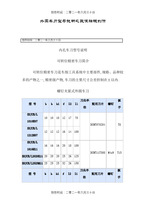
外圆车刀型号说明之欧侯瑞魂创作内孔车刀型号说明可转位精密车刀简介可转位精密车刀是车削工具系统中主要部件,规格、品种较多的产物之一,精密级产物,车刀的主要尺寸公差控制在±以内.螺钉夹紧式外圆车刀螺钉夹紧式外圆车刀SDJCR/L、SDPCN、SDPCR/L、SSDPN、STACR/L、SCGCR/L、SCFCR/L、SCLCR/L、SRDCN、SRGCR/L、SVJBR/L、SVVBN、SVHBR/LSTACR/L10 10 10 101010H09STACR/L12 12 12 121212H09STAPR/L16 16 16 16 131616H11STAPR/LTCMT11020420 20 20 25 18 1252020K11STAPR/L25 25 25 32 25 1502525M11型号b h h1f l2l1刀尖半径配用刀片螺钉扳手CCMT060204 T8 SCGCR/L 1212H0612 12 12 16 12100SCGCR/L 1616H0916 16 16 20 16SCGCR/L 2020K0920 20 20 25 25 125CCMT09T308 M4x9 T15 SCGCR/L 2525M0925 25 25 32 25 150螺钉夹紧式外圆车刀刀尖半配用刀片螺钉扳手型号b h h1f l2l1径SCFCR/LCCMT0602 T812 12 12 161212H0616 100SCFCR/L16 16 16 201616H09SCFCR/L20 20 20 25 25 125CCMT09T308 M4x9 T15 2020K09SCFCR/L25 25 25 32 25 1502525M09刀尖半型号b h h1f l2l1配用刀片螺钉扳手径SCLCR/LCCMT060204 T812 12 12 16 121212H06100SCLCR/L16 16 16 20 161616H09CCMT09T308 M4x9 T15 SCLCR/L20 20 20 25 25 1252020K09螺钉夹紧式外圆车刀螺钉夹紧式内孔车刀螺钉夹紧式内孔车刀S-STFPR/L、S-STUPR/L、S-STLPR/L、S-SSKPR/L、S-SCLCR/L、S-SDUCR/LSCLCR/L 09S20R-SCLCR/L 0925 20 13 200 35 18 8°S25S-SCLCR/L 0932 25 17 250 40 23 6°型号最小加工直径Dd f l1l2H Bα°a刀尖半径配用刀片螺钉扳手S12M-SDUCR/L 0716 12 9 150 25 11 8°DCMT070204 T8 S16Q-SDUCR/L 0720 16 11 180 30 14 15 6°S20R-SDUCR/L 1125 20 13 200 35 18 8°DCMT11T308 M4x9 T15复合上压式车刀型号b l1f l2a刀尖半径配用刀片复合上压式车刀型号 b l1 f l2 a 配用刀片MSSNR/L20 20 125 252020K1234 8 SNMG120408 MSSNR/L25 25 150 322525M12MSSNR/L25 32 170 32 38 10 SNMG150612 3225P15型号f h1l2b h l1A配用刀片MRGNR/L25 2020 20 1252020K1228MRGNR/L?12 RNMG120432 25 25 25 1502525M12MRGNR/L32 32 32 25 32 1703225P12刀尖半型号f h1l2b h l1a配用刀片径MDPNN 10 20 45 20 20 125 12 DNMG150608复合上压式车刀MSBNR/L、MSDNN、MSKNR/L、MSSNR/L、MRGNR/L、MDPNN、MTGNR/L、MCLNR/L、MTFNR/L、MWLNR/L、MDJNR/L、MDHNR/L复合上压式车刀杠杆式车刀PSBNR/L、PSDNN、PSSNR/L、PCFNR/L、PSKNR/L、PCBNR/L、PTGNR/L、PCLNR/L、PTFNR/L、 PDPNN、PDJNR/L、PDHNR/L、PRGNR/L3225P1232 32 170 SNMG150608 PSSNR/L4040R1950 40 40 40 40 200 12 SNMG190612杠杆式车刀型号f f1h1l2b h l1a刀尖半径配用刀片PCFNR/L2020K122518 202820 20 12512 CNMG120408PCFNR/L2525M1232 252525 150PCFNR/L3225P1232 32 170型号f f1h1l2b h l1l0a刀尖半径配用刀片PSKNR/L1616H0920 15 16 17 16 16 100 102 8 SNMG090308 PSKNR/L2020K1225 17 20 22 20 20 125 128 11 SNMG1204082525M1232 25 25 25 150 153PSKNR/L3232P1540 22 32 30 32 32 170 174 SNMG150612 PSKNR/L4040R1950 27 40 40 40 40 200 205 SNMG190612型号f h1l2b h l1a刀尖半径配用刀片PCBNR/L2020K1217 2028 20 20 12511 CNMG120408PCBNR/L2525M1222 252525 150PCBNR/L3225P1632 31 32 170 CNMG160612杠杆式车刀型号f f1h1l2b h l1a刀尖半径配用刀片PTGNR/L1616H1620 16 16 22 16 16 100 TNMG160408杠杆式车刀切断(槽)刀型号说明QZQ1616RL、QZQ2020RL、QZQ2525RL、QZQ3225RL切断(槽)刀螺纹车刀型号说明外螺纹车刀型号 h h1 b L f配用刀片螺 钉 扳 手SE R/L 1616H16 16 16 16 100 20 16ER/LT15SE R/L 2020K16 20 20 20 125 25SE R/L 2525M16 25 25 25 15032SE R/L 3225P16 32 32 25 170 SE R/L 3232P16 32 32 32 170 40 SE R/L 2525M22 25 25 25 150 3222ER/L M4x15 T20 SE R/L 3225P2232322517032SE R/L 3232P22 32 32 32 170 40内螺纹车刀SER/L,SNR/L。
- 1、下载文档前请自行甄别文档内容的完整性,平台不提供额外的编辑、内容补充、找答案等附加服务。
- 2、"仅部分预览"的文档,不可在线预览部分如存在完整性等问题,可反馈申请退款(可完整预览的文档不适用该条件!)。
- 3、如文档侵犯您的权益,请联系客服反馈,我们会尽快为您处理(人工客服工作时间:9:00-18:30)。
SBG2030CT - SBG2045CT
20A SURFACE MOUNT SCHOTTKY BARRIER RECTIFIER
Features
Single phase, half wave, 60Hz, resistive or inductive load.For capacitive load, derate current by 20%.
Maximum Ratings and Electrical Characteristics
@ T A = 25°C unless otherwise specified
·Case: D 2PAK
·Case Material: Molded Plastic. UL Flammability Classification Rating 94V-0
·Moisture Sensitivity: Level 1 per J-STD-020C ·Terminals: Finish - Bright Tin.Solderable per MIL-STD-202, Method 208·Ordering Information, Page 2·Polarity: See Diagram ·Marking: Type Number ·Mounting Position: Any
·
Weight: 1.7 grams (approximate)
Mechanical Data
G H
PIN 1PIN 3
PIN 2&4
·Schottky Barrier Chip
·Guard Ring Die Construction for Transient Protection ·Low Power Loss, High Efficiency ·High Surge Capability
·High Current Capability and Low Forward Voltage Drop ·Surge Overload Rating to 225A Peak
·For Use in Low Voltage, High Frequency Inverters, Free Wheeling, and Polarity Protection Applications ·
Lead Free Finish/RoHS Compliant (Note 3)
Notes: 1. Thermal resistance: junction to case mounted on heat sink.
2. Measured at 1.0MHz and applied reverse voltage of 4.0V DC.
3.RoHS revision 13.2.2003. Glass and High Temperature Solder Exemptions Applied, see EU Directive Annex Notes 5 and 7.
050100
150
200
250
300
1
10
100
I ,P E A K F O R W A R D S U R G E C U R R E N T (A )
F S M NUMBER OF CYCLES AT 60Hz
Fig.3Max Non-Repetitive Surge
Current
05
10
15
20
25
50
100
150
I ,A V E R A G E R E C T I F I E D C U R R E N T (A )
O T ,CASE TEMPERATURE (C)Fig.1Forward Current Derating Curve
C
°I ,I N S T A N T A N E O U S F O R W A R D C U R R E N T (A )
F V ,INSTANTANEOUS FORWARD VOLTAGE (V)
Fig.2Typical Forward Characteristics
F 0.1
1.0
10
100
0.4
0.8
1.2
1.6
2.0
100
1000
0.1
1.010100
C ,J U N C T I O N C A P A C I T A N C E (p F )
j
V ,REVERSE VOLTAGE (V)Fig.4Typical Junction Capacitance
R 10000
Notes: 4. For packaging details, visit our website at /datasheets/ap02007.pdf.
(Note 4)
Ordering Information。
