WM526型.电子油门踏板
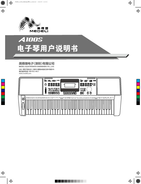
Medeli A100S 钢琴说明书
注意事项警告该产品的正常功能可能会遭受强电磁干扰。
如果出现这种情况,只需简单地按照用户说明书描述步骤将产品恢复初始设置。
当产品的功能无法恢复时,请在其他位置使用本产品。
装箱单尊敬的用户,当您选购本琴后,请检查以下物品是否齐全: 琴体 琴谱架 12V外接电源 用户说明书售后保修证书注意事项在操作使用前,请先仔细阅读以下内容。
请将本说明书妥善保管,以便将来随时查阅。
电源当从电源插座中拔出电源线插头时,请务必抓住插头。
请不要直接拽拉电源线,否则可能会导致损坏。
请勿用多路连接器将设备连接到电源插座上,否则可能会使插座过热。
设备不使用时,或者在雷雨暴风期间,请从插座上拔下电源插头。
如果您使用了其他类型的电源适配器,可能导致火灾和电击。
为了确保使用安全,设备不使用时,或者在雷雨暴风期间,请从插座上拔下电源插头。
连接在将本设备连接到其他设备之前,请关闭所有设备的电源开关。
这将有效防止设备故障或防止损坏其他设备。
位置请勿将设备放置于以下环境中,以免设备发生变形、变色或其他更严重的损害:阳光直射处、暖气旁多尘土、高温、高湿或可能产生强烈震动或冲击的位置 接近磁场处对其他设备的干扰将此设备放置在电视机、收音机、手机的周围可能引起干扰。
使用此设备时,请与电视机和收音机、手机保持适当的距离。
维护保养只能使用柔软的干布清洁此设备。
请勿使用涂料稀释剂、溶剂、清洁液或浸了化学物质的抹布。
请勿对开关或控制按钮用力过猛。
处理避免纸张、金属或其他杂物进入设备内部。
如果发生此类情况,请拔掉墙上电源插座中的插头。
然后请具有资格的美得理维修人员对设备进行检查。
在移动设备之前,请断开所有的电源。
目录面板控制与屏幕显示前面板..........................................................................4后面板..........................................................................4液晶显示......................................................................5演奏前的准备电源供电......................................................................6安装琴谱架...................................................................6外部连接连接耳机......................................................................7连接踏板......................................................................7连接电脑......................................................................7电源开关与主音量........................................................8示范曲..........................................................................8演奏音色......................................................................9播放节奏. (9)播放歌曲....................................................................10录音............................................................................10演奏各种乐器音色音色选择....................................................................11双音色........................................................................11下音色........................................................................11演奏各种风格伴奏演奏自动伴奏(只演奏打击乐声部).........................12演奏自动伴奏(所有声部).......................................12伴奏段落....................................................................12演奏不同的伴奏段落..................................................13渐强/渐弱...................................................................13伴奏音量控制.............................................................13和弦演奏指法. (14)速度调节....................................................................15功能菜单音调...........................................................................16分离点设置................................................................16节拍类型....................................................................17踏板定义....................................................................17均衡器设置................................................................17混响类型....................................................................17混响深度....................................................................18合唱类型....................................................................18合唱深度....................................................................18和声类型....................................................................18MIDI通道设置............................................................19自动关机设置.............................................................19调音台 (19)演奏各种音色效果八度...........................................................................20力度响应....................................................................20节拍器.......................................................................20延音效果....................................................................20弯音效果....................................................................21颤音效果....................................................................21数码效果....................................................................21移调...........................................................................21和声...........................................................................21面板注册记忆设置记忆库........................................................................22存储/调用注册记忆.....................................................22可存储的数据. (22)单触键设置................................................................22录音录音准备....................................................................23启动录音....................................................................23结束录音....................................................................23录音回放....................................................................24录音删除....................................................................24示范曲 (24)钢琴演奏模式.............................................................25歌曲歌曲播放....................................................................25歌曲控制....................................................................25歌曲学习....................................................................26和弦字典模式1 和弦学习模式...................................................27模式2 和弦测试模式...................................................27踏板功能多功能踏板.................................................................28MIDI功能什么是MIDI?..............................................................29MIDI的主要应用.........................................................29故障排除....................................................................30规格...........................................................................30附录音色表........................................................................31节奏表........................................................................38歌曲表........................................................................41示范曲表....................................................................43MIDI执行表. (44)面板控制与屏幕显示前面板后面板1.【电源】开关打开或关闭电源。
乐罗沃-沃米3相异步TEFV刹车电动机维修指南说明书
(F)LS (ES, IA, MV, PX), FCRThis document complements the general instructions ref. 1889 (recommendations), ref. 3770 (LS), ref. 4850 (LSES LS2/IE2),ref. 3255, 3385 (ATEX specific recommendations) and the specific instructions ref. 2908 (FCR brake motor installation).FCR brake motors are monobloc units consisting of an induction motor and a failsafe brake system (safety brake).This motor benefits from the experience of one of the largest manufacturers in the world, using state-of-theart technology in automation, specially selected materials, rigorous quality control. As a result, the regulatory authorities have awarded our motor factories the ISO 9001 - Edition 2008 international certificate.EC conformity: motors conform to the harmonized standard EN 60034 (IEC 34) therefore with the low voltage Directive 2006/95/EC and as EC marked.The noise level of the machines, measured under normal conditions, conforms to the requirements of the standard (IEC 34-9).IMPORTANTmanufacturer’s guarantee.standards).Particular attention should be given to the equipotential ground or earthing connections.Workforce safety: protect all rotating devices before power-up. If running a motor without fitting a coupling device, carefully immobilise the key in its location. All measures must be taken to ensure protection from the risks presented by rotating parts (sleeve, pulley, belt, etc.). Beware of backdriving• mains voltage disconnected and no residual voltage present• careful study of the causes of the stoppage (blocked transmission - loss of phase - cut-out due to thermal protection - lack of lubrication, etc.)PREFACE: ATEX TRAININGSpecific ATEX marking ➉0080 : INERIS identification number (Notified Organisation) T (max): Maximum surface temperature: 125°C for example : Specific marking Db, Dc: Protection level of equipmentII 2D Ex tb IIIC : Group II, category 2, Dust or: Attestation n° : Type test attestation n° issued by INERISII 3D Ex tc IIIB : Group II, category 3, non-conducting Dust (réf. 3255 instructions)Those persons required to work on electrical installations and equipment in zones where there is a risk of explosion must be specially trained in the necessary skills.In effect, they must be familiar not only with the electrical risks, but also with those that are due to the chemical properties and physical characteristics of products used in the installation (gas, vapour, dust), as well as the environment in which the equipment operates. These elements dictate the risk of fire and explosion.In particular, they must be informed and aware of the specific safety reasons and requirements in order to adhere to them.For example:- do not open when powered up, - do not manoeuvre when on load,- do not open when powered up in atmospheres - wait several minutes before opening,containing explosive dust, - replace the seals tightly to ensure watertightness.- do not separate when powered up,CONTENTS1 - IDENTIFICATION (13)1.1 - Standard nameplate (13)1.2 - Marking (13)2 - EXPLODED VIEW AND PARTS LIST FOR FCR BRAKE MOTORS (14)2.1 - Exploded view for FCR brake motors (14)2.2 - Parts list for FCR brake motors (14)3 - SPARE PARTS (14)3.1 - Procedure (14)3.2 - Wearing parts (14)4 - MAINTENANCE (15)4.1 - Dismantling for FCR brake motors (15)4.2 - Reassembly for FCR brake motors (15)4.3 - Adjustments (15)4.4 - Braking torque (15)4.5 - Electro-magnet characteristics (16)4.6 - Special operating conditions (16)4.7 - ATEX operating (16)5 - TROUBLESHOOTING GUIDE (17)6 - WIRING DIAGRAMS......................................................................................................................................................................18-19 NOTE : Leroy-Somer reserves the right to modify its product characteristics at any time to incorporate the latest technological developments. The information contained in this document may therefore be changed without prior warning.Copyright 2008 : MOTEURS LEROY-SOMER. This document is the property of MOTEURS LEROY-SOMER. It cannot be reproduced in any form without prior authorisation. All brand names are registered trademarks.e n1 - IDENTIFICATION1.1 - Standard nameplateFollowing details indicated on name plate:IP55 IK08 / IP65 IK08 : Index of protection*S1 : Duty % : Duty (operating) factor ...C/h : Number of cycles per hour40 °C : Contractual ambient operating temperature (I) cl. F : Insulation class F Hz : Supply frequency kW : Rated output power cos j : Power factor A : Rated current D : Delta connection Y : Star connectionShock resistanceThe motor can stand a weak mechanical shock (IK 08 according to EN 50-102). The user must provide additional protection if there is a risk of greater mechanical shock.Specific ATEX marking0080 : INERIS identification number (Notified Organisation): Specific markingII 2D Ex tb IIIC : Group II, category 2, Dust or:II 3D Ex tc IIIB : Group II, category 3, non-conducting Dust T125°C : Maximum surface temperature: 125°C Db, Dc : Protection level of equipment Ta : Ambient temperature: -25°C; 40°C for example Attestation n° : Type test attestation n° issued by INERIS1.2 - MarkingEnsure that the nameplate conforms with the order specifications on receipt of the motor.LS(ES) FCRATEX Zone 22 : (F)LS FCRATEX Zone 21 : (F)LS(PX) FCRINERIS n° 03ATEX 0012X only applies to FCR brakeLegal mark indicating that the equip-ment conforms to the requirements of the European Directives.2 - EXPLODED VIEW AND PARTS LIST FOR FCR BRAKE MOTORS2.1 - Exploded view for FCR brake motors2.2 - Parts list for FCR brake motors3 - SPARE PARTS3.1 - ProcedureAll orders for replacement parts must quote:- the complete motor type, its number and the information given on the nameplate (see §1);- number and designation of parts (the part numbers can be found on the exploded view § 2.1 and their description in the parts list § 2.2).In the case of flange mounted motors indicate the type of flange and its dimensions Ø PCD (B5 for flange-mounted, B14 for facemounted or MI integral mounting) and details of gearbox, when fitted.In order to ensure the safety and good working order of our brake motors, we recommend the use of original manufacturer replacement parts.If this advice is not followed, the manufacturer cannot be held responsible for any subsequent damage.3.2 - Wearing partse n4 - MAINTENANCEdisconnect the brake motor from its power supply 4.1 - Dismantling for FCR brake motors- Dismantle the brake motor using the correct tools (hub remover, bearing remover, plastic or leather mallets, correctly sized keys and screwdrivers, circlips pliers, etc.).- Disconnect the brake motor from its power supply.- Open the terminal box, locate the wires and mark their position (power supply to the motor and the brake, probes, etc.).- Disconnect the power supply wires from the motor terminal block and the brake power supply unit (+ and - terminals).- Unscrew the handle of the lever 53.1 when fitted (following procedure §4.2).- Unscrew the cover screws 40, remove the steel cover 23.- Remove the brake nut 24.- Remove the sealing ring 50.- Place an extractor with 2 arms pressing on the end of the shaft and two arms on the armature pins 11.- Remove the brake lining fan 15 and the armature 11.- Mark the position of the springs 28 and remove them.- Unscrew the assembly rods 5.- Put aside the front shield 3.- Pull out the stator housing 1 taking care not to damage the winding.- Remove the internal circlip 6 to free the brake shield 8.- Clean the parts:• by blowing the electrical parts (do not use solvents or products containing moisture);• using a non slippery degreasing agent for the mechanical parts;• using a scraper for the flanges;• if parts 11 and 15 are slippery: change part 15 and degrease part 11 with a non slippery degreasing agent.- Change the seals and the bearings.- Disconnect the bridge rectifier and check the insulation of the stator (>10 megOhms).- Mark all faulty parts so that replacement parts can be ordered.4.2 - Reassembly for FCR brake motors- Lightly grease the shafts and bearing cages.- Cover the seal lips with grease and put the seal back carefully (use the protection sockets of the drive shaft keyway).- Working in reverse order, assemble the motor.- Replace the pressure springs 28, change the sealing ring 50.- Position the housing 11, reposition the brake lining fan 15.- Adjust the air gap (see above).- Position the sealing ring 50.- Fit on the lever 53 (following procedure bellow).- Replace the steel cover 23 and fix it using the cover screws 40.- Reconnect the brake power supply unit, and any probes, and then the motor - making sure that the wires are in the correct order - and close the terminal box.- Check that it works correctly (if this is not the case check that the release lever is in the right position before coupling to the machine).Desmantling, reassembling the brake lever (option: DLRA)Desmantling the brake lever DLRA- Unscrew the handle of the lever 53.1 (if fitted on the hand release lever).- Unscrew the cover screws 40, which keep the cover 23 in place.- Unscrew the two screws 53.3, release the spring 53.4.- The hand release 53.2 may be removed.Reassembling the brake lever DLRA- Position the hand release 53.2 around the brake housing.- Assemble the screw on the right 53.3 (when viewed from the output shaft of the motor).- Assemble the other screw 53.3 and get ready with the spring 53.4.- Compress the spring 53.4 close to the maximum distance larger than the section of brake lever 53.2 and smaller than the distance between the screws on the brakes housing.- Assemble the cover 23 and the screws 40.- The handle 53.1, clipped to the stator, will be assembled, if needed to release the brake.4.3 - AdjustmentsAdjusting the air gapThe air gap needs to be adjusted when the release mechanism no longer functions normally.- Unscrew the handle of the lever 53.1 when fitted (following procedure §4.2).- Unscrew the cover screws 40 which keep the steel cover 23 in place.- Remove the steel cover 23. Unscrew the brake nut 24, and remove the sealing ring 50. Clean the parts: removal of lining’s friction dust. Insert a 0.4 mm shim between the brake shield 8 and the armature 11. Tighten the brake nut 24 so as to obtain working play of 4/10th between armature 11 and brake shield 8 (the shim should slip slightly).- The brake nut 24 should be changed after 3 adjustments.- Replace the sealing ring 50. Replace the lever 53 (following proce-dure §4.2).- Replace the steel cover 23 and tighten the cover screws 40.Adjusting the braking torque- The braking torque depends on the number of springs and their colour; use the values shown in the table on §4.4.53.153.253.353.44.5 - Electro-magnet characteristics (à 20°C) ± 5 %4.6 - Special operating conditions- Thermal protection (see 2908 § 2.6)- Space heaters (see 2908 § 2.6)- Temperatures: storage and ambientNote: Ta = ambient temperatureIf it has been stored at a temperature lower than -10°C, heat the motor and turn the shaft manually before operating the machine.If used at a temperature lower than -25°C, the motor does not require a temperature sensor to be fitted. It can be fitted with thermocouples. Our standard motors are intended to operate at an ambient temperature between -25°C and 40°C.- Surface temperatureAs standard, the maximum surface temperature of our motors is 125°C with a maximum ambient temperature of ≤ 40°C. Without derating the motor, the maximum surface temperature will be:• 135°C if 40°C ≤ Ta ≤ 50°C• 145°C if 50°C ≤ Ta ≤ 60°C- Contactors - isolatorsIn all cases, the contactors, isolators, etc. must be installed and connected in an enclosure offering a degree of protection and surface temperature compatible with the installation zone, or outside danger zones (outside zones 20, 21 and 22).- ConnectionParticular attention must be paid to the nameplate so as to choose the correct type of connection for the supply voltage.- Bearing maintenanceWhen you detect on the motor:- a noise or abnormal vibration,- abnormal temperature rise in the bearing even though it is lubricated correctly, the state of the bearings must be checked.Damaged bearings must be replaced as soon as possible to prevent worse damage to the motor and the driven equipment. When one bearing needs to be replaced, the other bearing must also be replaced.The free bearing allows the rotor shaft to expand (make sure it isidentified during dismantling).- SealsAfter removing the drain plugs, replace them in order to ensure that the motor conforms to IP 55 or 65 protection. Replace the removed seals with new seals of the same type. Clean the orifices and plugs before replacing.On removal, and at least once a year, replace seals on the shaftway, the shield spigots and the terminal box cover with new seals of the same type, after cleaning the parts. The shaftway seals must be fitted using grease of the same type as the bearings.4.7 - ATEX operating- IP 65 protection for the motor- Variable speed utilisationSpecial precautions need to be taken when these motors are powered by a frequency inverter or voltage controller:Motors supplied by a frequency inverter must be fitted with sensors and a sensor on the DE shield if appropriate. These sensors must be connected to a motor cut-off device placed outside the explosive zone, so that the maximum surface temperature (indicated on the device) is never reached (Ref. 2908 § 2.6).Particular points:- incremental encoder utilisation requires ATEX homologation (IP 65) of the encoder.e n5 - TROUBLESHOOTING GUIDE6 - WIRING DIAGRAMSe nMOTEURS LEROY-SOMER SAS - RCS 338 567 258 ANGOULÊME - CAPITAL DE 65 800 512 €。
百福2591操作说明书
操作说明书
该操作说明书适用于序列号 2 766 760 和软件版本 0389/001 以上的机器 296-12-19 128/014 Betriebsanleitung chin. 01.10
本使用说明适用于所有在第 3 章“技术数据”中所列类型的机器及其下属 分机型的机器。 本缝纫机的校验说明可以免费从下列网址下载: www.pfaff-industrial.de/pfaff/de/service/downloads 除网上下载之外,也可以用订货号 296-12-19 129/014 订购校验说明书。
8.01 8.02 8.03 8.04 8.05 8.06 8.07 8.08 8.09 8.10
9 9.01 9.01.01 9.01.02 9.01.03 9.01.04 9.02 9.03
10 10.01
11 11.01 11.02 11.03 11.04 11.05
12
装针...................................................................................................................................... 22 绕底线、底线预张力调节 ..................................................................................................... 23 取出 / 装入梭壳 ......................................................................................................24 梭壳穿线 / 调节梭心线的张力 ..................................................................................24 穿上线/上线张力调节 ...............................................................................................................25 输入针距 ....................................................................................................................................26 接通/关闭缝纫功能 .............................................................................................................. 26 输入起始套结和终点套结的线迹 ...............................................................................................27 输入/更改代码编号 .............................................................................................................. 28 梭心线检查........................................................................................................................... 30
海马S5 车辆使用说明书
图示符号您的车上使用下列表格中的部分通用符号,用于显示警告信息和指示信息:标识标识定义汽车防盗报警信号装置标志前照灯远光操纵件及信号装置标志近光灯操纵件及信号装置标志位置(侧)灯操纵件及信号装置标志前雾灯操纵件及信号装置标志后雾灯操纵件及信号装置标志前照灯水平手调机构操纵件标志标识标识定义转向指示灯操纵件及信号装置标志危险报警灯操纵件及信号装置标志前风窗玻璃刮水器及洗涤器组合操纵件标志车窗升降操纵件标志后风窗玻璃除霜和除雾操纵件及信号装置标志发动机排放系统故障警报信号装置标志点烟器操纵件标志标识A/C标识定义空调系统操纵件及信号装置标志安全气囊故障信号装置标志燃油液面高度指示器和警报信号装置标志蓄电池充电指示器和警报信号装置标志发动机冷却液温度指示器和警报信号装置标志喇叭操纵件标志发动机盖操纵件标志标识标识定义后行李厢盖操纵件及信号装置标志驾驶员/前排乘员安全带警报信号装置标志机油压力指示器及警报信号装置标志制动防抱系统故障信号装置标志电喷发动机故障信号装置标志车门打开操纵件及信号装置标志内部空气循环操纵件及信号装置标志标识标识定义制动系统故障信号装置头部风向位置操纵件及信号装置标志头/脚部风向位置操纵件及信号装置标志脚部风向位置操纵件及信号装置标志脚部/除霜风向位置操纵件及信号装置标志汽车稳定控制系统(ESC )关闭操纵件及信号装置标志汽车稳定控制系统(ESC )操纵件及信号装置标志标识标识定义胎压监测新号装置以下标识出现在S5系列乘用车的部分车型上:适用车型HMA7151GC4W HMA7151GC4W HMA7151GC4W HMA7151GC4W HMA7151GC4W HMA7151GC4W HMA7151GC4W 标识PR N D S +-标识定义自动变速箱驻车挡(Park )操纵件及信号装置标志自动变速箱倒车挡(Reverse )操纵件及信号装置标志自动变速箱空挡(Neutral )操纵件及信号装置标志自动变速箱自动经济模式前进挡(Drive )操纵件及信号装置标志自动变速箱自动动力模式前进挡(Sport )操纵件及信号装置标志自动变速箱手动模式(Manual )操纵件增挡标志自动变速箱手动模式(Manual )操纵件减挡标志适用车型HMA7151GA4W HMA7151GA4W HMA7151GA4W HMA7151GA4W HMA7151GA4W HMA7151GA4W HMA7151GC4W标识123456标识定义自动变速箱手动模式(Manual )一挡信号显示标志自动变速箱手动模式(Manual )二挡信号显示标志自动变速箱手动模式(Manual )三挡信号显示标志自动变速箱手动模式(Manual )四挡信号显示标志自动变速箱手动模式(Manual )五挡信号显示标志自动变速箱手动模式(Manual )六挡信号显示标志变速箱(CVT )故障警报信号装置标志注:本系列乘用车只能使用辛烷值为93#(研究法)或93#以上的无铅汽油,禁止使用含铅的汽油。
VOLVO FM 卡車產品指南说明书
32 4
Эۨ⧕ٶቷት܃
路面到車頂僅有 261 公分,對於需要特 別注意高度的運輸情況來說是最好的選
擇。νࠅଉɝə༆dሗਞቡୋ 32 ࠫf
᎘ዱ 主動式轉向頭燈、靜態轉向輔助照明 燈、有效率的遠光燈等各式照明。νࠅ ଉɝə༆dሗਞቡୋ 24 ࠫf
24
VOLVO ࣵˏذᏗ 省油、扭力強勁的 11 與 13 公升引 擎。依照您的工作內容做出最佳選擇。 νࠅଉɝə༆dሗਞቡୋ 10 ࠫf
8
*I-See සனਯ Euro 5 ʿ Euro 6 ̹ٙఙʕԶf
ίɨս༩ݬj
ቇࣛԓf
I-See 知道斜坡路段何時結束。因此,一旦車 速在下坡路段開始增加時,它會適時地稍微施
加引擎煞車 (而非突然地重煞車),為即將到來 的道路地形做好準備。
ίսֵj ɓԬᕘ̮ٙਗɢ 當下坡路段緊接著上坡路段時,I-See 真的就 能發揮最大的功用。它讓卡車以慣性自行前進 到最大限速以蓄積上坡力道,讓卡車在上坡時 更省力。
ሗਞቡୋ 12 ࠫf
44
ৣ 專為您的工作及需求來打造卡車, 讓您工作起來更有效率。νࠅଉɝə
༆dሗਞቡୋ 44 ࠫf
5
છ
ᒔᆞவᅵٙછชk ఱ྅݊ቷትʃ܄ԓɓᅵf
如果您一整天都在開車,那麼您就知道良好的操控性有多重要。因為對開 卡車的人來說,駕駛舒適性絕對不只是要求舒適性而已。當卡車完美地回 應您的指揮時,您就能事半功倍並減少上半身拉傷的風險,進而降低發生 事故機率。
ഒ࿁ʔౢ˓ԓႡிਠٙჯਹf
我們從不允許工程師在大樑框架上方添 加任何多餘的東西。這個區域完全屬於 車體製造商管轄,目的就是提供他們充 分的彈性。
ɓΐਖ਼᙮ٙԓஹഐˆЗf
森兰SB200系列变频器使用手册V1.3
FC 键盘操作及显示设置................................................................................... 2 FF 通讯参数 ....................................................................................................... 2 Fn 厂家参数 ....................................................................................................... 2 FP 故障记录 ....................................................................................................... 2 FU 数据监视....................................................................................................... 2
3 安装及配线.......................................................................................................... 2
3.1 变频器的安装............................................................................................. 2 3.2 变频器部件的拆卸和安装......................................................................... 2 3.3 变频器的配线............................................................................................. 2 3.4 变频器电磁干扰的抑制方法..................................................................... 2
ssp210_CHN_电子油门操纵机构
2说明在电子油门操纵机构中,节气门只由电机来操纵。
因此就取消了油门踏板和节气门之间的波顿拉索。
这就是说:司机意愿经油门踏板传送到发动机控制单元,该控制单元再发出命令来调整节气门的位置。
因此发动机控制的单元就可以通过调整节气门的位置来改变发动机的输出扭矩,即使司机没有踏动油门踏板也可调节发动机扭矩。
这样可使得发动机管理系统之间和内部更好地协调工作。
下面将向您展示:电子油门机构绝不只是用导线代替了油门拉索,还有更多的内容需要您了解。
引言............................................4节气门调节....................................4系统说明......................................5调节过程......................................6系统结构......................................7具体的工作过程................................8系统元件.......................................10系统一览.....................................10发动机控制单元...............................11油门踏板模块.................................14节气门体.....................................16故障指示灯...................................22附加信号.....................................23功能图.........................................25自诊断.........................................26考考你.........................................30一览3节气门的调节机械式节气门调节这种结构是由司机踏动油门踏板,通过一根拉索以机械方式直接来调节节气门位置。
德力西E系列__说明书
..
..
致用户书
——现场安装运行注意事项
尊敬的用户:
感谢您选用德力西(杭州)变频器有限公司生产的 E 系列变频调速器,为 了您能更好的使用本产品,请注意以下几点:
1、变频器安装就位调试前,请对部件进行紧固处理,特别是导线部分连接螺栓, 不紧固会造成连接处发热引起火灾。
2、安装现场设计要合理,要保持良好的通风环境。
专业 word 可编辑
..
..
..
4.1 操作方式的选择 ....................................................................................... 46
4.2 试运行及检查............................................................................................ 46
4.2.1 试运行前的注意事项及检查 ............................................................ 46
4.2.2 试运行 ...................................................................................................... 47
5.1 基本功能 P0 组......................................................................................... 57
5.2 电机控制参数 P1 组................................................................................ 61
南京依维柯欧胜纯电动汽车 使用说明书

注意事项.......................................................... 69 车辆充电.......................................................... 74 电源总开关...................................................... 76 车辆起动.......................................................... 77 运行.................................................................. 79 低速提示音装置.............................................. 79 停车.................................................................. 80 突发事件及处理.............................................. 80 动力系统布置(70KWH) .............................. 83 动力系统布置(78KWH、88KWH) ............... 84 动力系统布置(90.7KWH) ........................... 85 汽车的合理使用.............................................. 90 正常运营车辆的使用要求.............................. 91 久放不用车辆的使用要求.............................. 91 充电机的使用.................................................. 91 电池保养的操作方法...................................... 92 使用辅助电瓶起动.......................................... 93 踏板.................................................................. 95 驻车制动.......................................................... 95 行车制动.......................................................... 96 车辆牵引.......................................................... 96 制动防抱死系统(ABS) ............................... 97 *车身电子稳定系统(ESP) .......................... 99
电子油门踏板国家标准

电子油门踏板国家标准电子油门踏板是汽车上的一个重要部件,它直接影响着汽车的加速性能和驾驶的舒适度。
为了规范电子油门踏板的设计、制造和使用,国家对电子油门踏板制定了一系列的标准,以确保汽车安全、可靠和高效。
首先,电子油门踏板国家标准对电子油门踏板的设计和制造提出了具体的要求。
在设计方面,标准规定了电子油门踏板的外观尺寸、结构布局、安装方式等方面的要求,以确保电子油门踏板在安装在汽车上时能够正常使用,并且不会对驾驶员的操作造成不便或危险。
在制造方面,标准要求电子油门踏板必须符合相关的材料和工艺标准,以确保其质量和可靠性。
其次,电子油门踏板国家标准对电子油门踏板的性能提出了具体的要求。
在性能方面,标准规定了电子油门踏板的响应速度、灵敏度、稳定性等方面的要求,以确保电子油门踏板能够准确地响应驾驶员的操作,并且能够在各种工况下稳定可靠地工作。
此外,标准还对电子油门踏板的耐久性、防水性、抗干扰能力等方面提出了要求,以确保电子油门踏板能够在各种恶劣的环境条件下正常工作。
另外,电子油门踏板国家标准对电子油门踏板的安装和使用提出了具体的要求。
在安装方面,标准规定了电子油门踏板的安装位置、安装角度、安装间隙等方面的要求,以确保电子油门踏板在安装在汽车上时能够正常使用,并且不会对汽车的其他部件造成影响。
在使用方面,标准规定了电子油门踏板的操作力、行程、行程曲线等方面的要求,以确保电子油门踏板能够满足驾驶员的操作习惯,并且能够提供舒适的驾驶体验。
总的来说,电子油门踏板国家标准对电子油门踏板的设计、制造、性能、安装和使用提出了具体的要求,以确保汽车上的电子油门踏板能够安全、可靠、高效地工作。
制定和执行这些标准,可以有效地提高汽车的安全性能,保障驾驶员和乘客的生命安全,促进汽车产业的健康发展。
因此,各汽车生产企业和相关部门都应当严格遵守这些标准,确保电子油门踏板的质量和性能符合国家标准的要求。
上汽大众新途观L使用维护说明书

本说明书适用于下列表中各种型号的上汽大众新途观L多用途乘用车。
用户在使用本公司产品以前,必须认真研读产品使用维护说明书,任何不当的使用、保养和修理都可能导致车辆的损坏及影响质量担保服务。
因此,在使用产品前请认真阅读本使用维护说明书,并对照表中的型号确认您的车型。
上汽新途观L多用途乘用车SVW64712AT DJS七挡自动变速器上汽新途观L多用途乘用车SVW64712BV DPL七挡自动变速器上汽新途观L多用途乘用车SVW64712CV DPL七挡自动变速器上汽新途观L多用途乘用车SVW64712DV DPL七挡自动变速器上汽新途观L多用途乘用车SVW64712EV DKX七挡自动变速器本使用维护说明书描述了该车型车辆在当前范围的配置、功能及操作的一般通用信息,但用户车辆的实际配置和功能等信息以具体交付时的为准。
本公司将持续对各种车型进行改进,各车型在外形、配置、功能和结构设计等方面也可能随时会发生变化,故本公司有权在法律法规允许的范围内对本说明书有关版本进行更改、补充,若用户对此有疑义请及时拨打上汽大众客户服务热线400-820-1111予以咨询。
未经本公司书面同意,不得复制、翻译或摘录本使用维护说明书。
上汽大众汽车有限公司依法保留对本说明书有关版本进行更改、补充等的一切权利。
中国印刷。
上汽大众汽车有限公司公司地址:中国上海安亭于田路邮政编码:201805企业标准号:Q/JQAB 354-2021Q/JQAB 355-2021致尊敬的用户尊敬的用户:感谢您对上汽大众的信任与厚爱!在您选择了上汽大众产品的同时,您已经启动了全新的汽车生活之旅。
在整个旅行过程中,上汽大众和旗下1000余家大众品牌特许销售商/特约维修站都将始终陪伴您左右。
衷心希望您的每一天行车生活,都因有上汽大众的同行而更精彩!如果您对车辆使用有任何疑问,上汽大众经销商随时随地为您提供帮助,我们的上汽大众客户服务中心全国统一寻呼400-820-1111也将是您的坚强后盾。
D2使用说明书[1]
![D2使用说明书[1]](https://img.taocdn.com/s3/m/88136d67453610661ed9f47e.png)
按键
后窗定时加热
1、按此键,后窗加热器工作,并在显示屏上显示,并自动加热15分钟后关闭,
此键在OFF状态下也能工作。
11号
按键
前玻璃吹风及 吹脚出风模式.
1、按下此键,吹风模式变为吹窗及吹脚模式。
2、在AUTO状态下按下此键,系统将退出自动模式进入手动状态下的吹窗及吹脚 模式,按键指示灯点亮显示状态.
提示:空调耗电量较大,建议当整车电量下降至20%时,请勿使用空调。
10.
按下警示灯开关,所有转向灯和转向指示灯闪烁。再次按下警示灯开关,所有转向灯和转向指示灯停止闪烁。组合仪表面板上 (转向灯信号)将同步闪烁。
11.
如图是驾驶员侧玻璃升降器开关,一共三个开关,两个控制玻璃升降开关,一个安全开关,安全开关按下后,副驾驶员侧的玻璃升降器开关失效,驾驶员侧控制右门玻璃升降开关仍然有效。
12号
按键,吹面及吹 脚
吹风模式为吹
面及吹脚同时 出风模式.
1、按下此键,吹风模式变为吹脚及吹面模式
2、在AUTO状态下按下此键,系统将退出AUTO模式,进入手动状态下吹前模 式,按键指示灯点亮显示状态.
13号
AC按键
开/关空调压缩 机
1、切换压缩机的工作状态并在此按键指示灯显示相应状态。
2、手动模式下,每按一次,压缩机的工作状态(开/关)切换一次。
工作。(正在执行的动作要进行完)
2、当点火钥匙打至“ON”档时,系统自动开启工作,系统启用用户上次设定的 工作方式或界面。(这种状态是关闭点火钥匙时,空调仍在工作,没有用OFF键将其关闭)。
3、当系统在OFF状态时,打开风扇或按下PTC,A/C或AUTO,系统将开启,启 用上次设定的工作方式或界面。此时的工作状态在按键灯指示.
永磁同步电动机的开环步进驱动器的研究

“ 跃” 形。 跳 波
} , : l ’ 1 _ ’ 1 . ▲ | 1 I r r
e 3 10 { h A l M .s1 0 Ss 1 ms t 10 0 0 / . / 0 p A c 33 0 h / 6 mA
免了在紧急情况下, 驾驶员误操作的发生。同时 , 此机构 的结构设计 结构上实现 了刹 车油 门一体化 的联动 ,在性能上 实现 了定速巡
参考了人机工程学原理 ,在设计时充分考虑从 人操纵的具体隋况, 航 、 油门和刹车的双重互锁, 这也是本课题设计的创新点。 本课题 合理设计了脚步操纵机构的力度 , 减轻了驾驶员的腿部疲劳 。电控 还运用 了人机工程学原理进行设计 , 更加符合 了人体操 纵机构的
L UAN u l J —i
( h n a gV c t n l n eh ia C l g ,h n a g10 4 ,hn ) S e y n oa o a a dT c ncl o e eS e y n 10 5 C ia i l
t 十 一 十 、± 十瞳 q 、 一 £ 、 ” 十 一 十 ’ l 十 — d ● 、t十 1 § ● q、 ‘十 毒 、t十 q、 l 十 1、 t 十 、 q、 ● l q、 t " 十 q、 十’、 t ●
【 摘
要】 步进电机是增量运动控制系统的主要执行机构。如果采用合适的驱动方式, 永磁 同步电
机 ( em nn ge Snhoo s trP M) 步进 电机 (t pn tr都 可 以.作在 步 进模 式 。 Pr aet nt ycrnu o, MS 和 Ma Mo Se igMo ) p o Y - 主要 研 究永磁 同步 电机 的开环 步进驱 动 器的理 论和 方法 。通过 对永磁 同步 电机 的驱动 方式 的深入 研 究
一种采用冗余设计的新型电子油门踏板[实用新型专利]
![一种采用冗余设计的新型电子油门踏板[实用新型专利]](https://img.taocdn.com/s3/m/6dd339b8f01dc281e53af0f1.png)
专利名称:一种采用冗余设计的新型电子油门踏板专利类型:实用新型专利
发明人:黄印玉,张长岭,尚勇,曹永辉,胡东平
申请号:CN201420096192.6
申请日:20140304
公开号:CN203752911U
公开日:
20140806
专利内容由知识产权出版社提供
摘要:本实用新型公开了一种采用冗余设计的新型电子油门踏板,踏板中配备的高精度霍尔传感器可将踏板角度信号转换成电压信号传至发动机或整车ECU,供其进行信号识别并控制发动机的油门开度及车辆速度。
踏板中配备的单轴两传感器可实现单侧传感器互检、双侧传感器他检功能,可在四路输出电压信号中有最多两个信号故障时,仍能保证车辆正常行驶。
全金属封闭设计的踏板结构具备抗干扰和环境适应性强的优点,并且霍尔传感器可保证踏板具备高精度和高可靠性,应用范围广。
申请人:北京比特英泰动力技术有限公司
地址:100081 北京市海淀区中关村南大街5号1区689号楼2层215
国籍:CN
更多信息请下载全文后查看。
ALT-SMY04EN 系列自动喷油坠油箱说明书
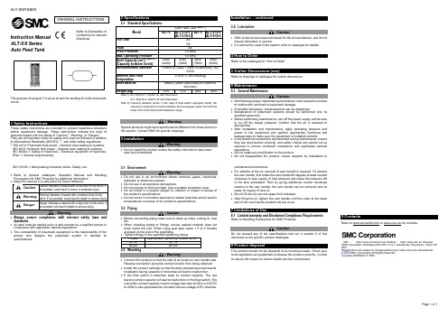
ALT-SMY04ENPage 1 of 1Instruction ManualALT-5/9 Series Auto Feed TankThe purpose of using ALT is as an oil tank for sending oil to the pneumatic circuit.1 Safety InstructionsThese safety instructions are intended to prevent hazardous situations and/or equipment damage. These instructions indicate the level of potential hazard with the labels of “Caution,” “Warning” or “Danger.” They are all important notes for safety and must be followed in addition to International Standards (ISO/IEC) *1), and other safety regulations. *1)ISO 4414: Pneumatic fluid power - General rules relating to systems. ISO 4413: Hydraulic fluid power - General rules relating to systems.IEC 60204-1: Safety of machinery - Electrical equipment of machines. (Part 1: General requirements)ISO 10218-1: Manipulating industrial robots -Safety. etc.• Refer to product catalogue, Operation Manual and Handling Precautions for SMC Products for additional information.not avoided, will result in death or serious injury.Warning• Always ensure compliance with relevant safety laws and standards.• All work must be carried out in a safe manner by a qualified person in compliance with applicable national regulations.• The compatibility of pneumatic equipment is the responsibility of the person who designs the pneumatic system or decides its specifications.2 SpecificationsALT-5(9)-IS-2: Switch off with float downNote 2) Capacity between levels: in the case of float switch equipped model, thecapacity is measured in levels between the level gauge upper limit and the lower limit of the float switch detective range.WarningSpecial products might have specifications different from those shown in this section. Contact SMC for specific drawings.3 InstallationWarning• Do not install the product unless the safety instructions have been read and understood.3.1 EnvironmentWarning• Do not use in an environment where corrosive gases, chemicals, saltwater or steam are present.• Do not use in an explosive atmosphere.• Do not expose to direct sunlight. Use a suitable protective cover.• Do not install in a location subject to vibration or impact in excess of the product’s specifications .• Do not mount in a location exposed to radiant heat that would result in temperatures in excess of the product’s specifications.3.2 PipingCaution• Before connecting piping make sure to clean up chips, cutting oil, dust etc.• When installing piping or fittings, ensure sealant material does not enter inside the port. When using seal tape, leave 1.5 to 2 threads exposed on the end of the pipe/fitting.3.3 MountingWarning• Connect this product so that the inlet of air locate on cam handle side. Reverse connection prevents normal function from being obtained. • Install this product vertically so that the drain exhaust face downwards. Installation facing upwards or horizontal will lead to malfunction.• If the float switch Is attached, keep its contact capacity. The use beyond contact capacity will lead to malfunction of the float switch. The use within contact capacity means voltage less than AC50V or DC75V to 200V is also applicable but included into low voltage of EC directive.Installation - continued3.4 LubricationCaution• SMC products have been lubricated for life at manufacture, and do not require lubrication in service.• If a lubricant is used in the system, refer to catalogue for details.4 How to OrderRefer to the catalogue for ‘How to Order’.5 Outline Dimensions (mm)Refer to drawings or catalogue for outline dimensions.6 Maintenance6.1 General MaintenanceCaution• Not following proper maintenance procedures could cause the product to malfunction and lead to equipment damage.• If handled improperly, compressed air can be dangerous.• Maintenance of pneumatic systems should be performed only by qualified personnel.• Before performing maintenance, turn off the power supply and be sure to cut off the supply pressure. Confirm that the air is released to atmosphere.• After installation and maintenance, apply operating pressure and power to the equipment and perform appropriate functional and leakage tests to make sure the equipment is installed correctly.• If any electrical connections are disturbed during maintenance, ensure they are reconnected correctly, and safety checks are carried out as required to ensure continued compliance with applicable national regulations.• Do not make any modification to the product.• Do not disassemble the product, unless required by installation ormaintenance instructions.• For addition of the oil, removal of cam handle is required. To remove the cam handle, first rotate the cam handle 90 degrees at least counter clockwise to stop supply of inlet pressure and make the pressure left in the tank exhausted. Then by giving additional counter clockwise rotation to the cam handle, the cam handle can be removed and be ready for supply of new oil.• Do not fill the oil over the upper limit indicated.• After filing the oil, tighten the cam handle until the collar at the lower part of the cam handle contacts the top cover.7 Limitations of Use8.1 Limited warranty and Disclaimer/Compliance Requirements Refer to Handling Precautions for SMC Products.CautionDo not exceed any of the specifications laid out in section 2 of this document or the specific product catalogue.8 Product disposalThis product should not be disposed of as municipal waste. Check your local regulations and guidelines to dispose this product correctly, in order to reduce the impact on human health and the environment.9 ContactsRefer to or www.smc.eu for contacts.URL : http// (Global) http// www.smc.eu (Europe) 'SMC Corporation, Akihabara UDX15F, 4-14-1, Sotokanda, Chiyoda-ku, Tokyo 101 0021Specifications are subject to change without prior notice from the manufacturer. © 2020 SMC Corporation All Rights Reserved. Template DKP50047-F-085JORIGINAL INSTRUCTIONS。
智享踏板适配 15+款林肯航海家、MKX(升级版)电动踏板安装说明书

电动踏板安装说明书智享踏板适配15+款林肯航海家、MKX(升级版)PW033879支架部分安装说明一、注意事项1.本说明书中的所有图片仅供参考,图片与实物有可能不同,但安装方法一致。
2.为方便您安装,请在安装前认真阅读该商品使用说明书;安装时需注意保护好您爱车的表面,避免刮花。
3.请定期检查和车连接的所有配件是否松动,以确保使用安全。
4.安装工具要求:锂电池电动扭力扳手需使用12-18V以内;二、包装清单踏板(左右对称)前支架(左右对称)后支架(左右对称)前顶车支架后顶车支架(左右对称)平垫圈D10弹簧垫圈D10 大垫圈D10型螺栓2号塑料卡块φ型螺栓3号六角螺母M10型螺栓6号塑料卡块φ弹簧垫圈D8 大垫圈D8六角螺母 M8 六角螺母 M12弹簧垫圈D12 大垫圈D12型螺栓3 M12塑料卡块φ铝支架三铝支架二铝支架一三、安装步骤(两边踏板安装方法一致,只描述一边的安装方法)第一步:了解踏板构成,以及安装顺序,参考下图:第二步:首先把原车车底护板拆下,找到车底对应安装孔,把对应支架安装上的螺钉或胶塞取下,以下所有安装螺丝螺栓先不要全部锁紧; (1) 车底安装孔位图:左后支架右踏板安装示意图左踏板右后支架左前支架右前支架前顶车支架后顶车支架前顶车支架后顶车支架前支架安装点后支架安装点前顶车支架安装点车头方向车头方向(2)安装前支架:首先把原车安装位置对应螺钉或胶塞取下,首先把塑料卡块装在T 型螺栓上,然后在对应位置放上T 型螺栓,再装上支架,然后用配件锁上(左右两边安装方法一致)(2) 安装后支架(左右两边安装方法一致)(3) 安装前顶车支架(左右两边安装方法一致)(4) 安装后顶支架(左右两边安装方法一致);与后支架共用车头方向第三步:安装铝支架:(1) 安装铝支架组件二:把铝支架组件二与前支架(左)连接,首先装上铝支架组件二,用M10螺母、D10弹簧垫、D10平垫片锁上,注意先不锁紧,待安装踏板最后拧紧; 提示:用同样方法安装另一边,把铝支架组件一与前支架(右)连接,用D10平垫片、D10弹簧垫、M10螺母锁上,待安装踏板最后锁紧;(2) 安装铝支架组件三: 把铝支架组件三与后支架(左)连接,首先装上铝支架组件三,然后用M10螺母、D10弹簧垫、D10平垫片锁上,注意先不锁紧,待安装踏板最后拧紧; 提示:用同样方法安装另一边把支架组件三与后支架( )连接,用D10平垫片、D10弹簧垫、M10螺母锁上,待安装踏板最后锁紧;第四步:安装踏板(左右两边安装方法一致)将踏板上的T型螺栓螺母、弹簧垫、平垫片拆下,然后让踏板与连接支架锁上,调整面板前后距离后,扭紧螺母。
讯闻电子 JSCNC 系列运动控制器说明书

JSCNC系列运动控制器-说明书性能简介:通讯口:COM1:RS232 FX协议,MODBUS,波特率:1200~115200COM2:RS485 FX协议,MODBUS,波特率:1200~115200COM3:RS232 FX协议,MODBUS,波特率:1200~115200COM4:RS485 FX协议,MODBUS,波特率:1200~115200USB:FX协议运动功能:1.XYZ任意两轴圆弧插补,XYZ三轴直线圆弧插补,XYZ任意两轴螺旋插补2.A轴自定义运行3.G代码和M代码预读,解析和扩展4.手轮控制4轴,执行G代码5.单轴最大100K,高速型400K6.G代码无限制行数7.MicroSD卡和U盘读写,最大16G。
8.S型加减速曲线和梯形加减速曲线完美结合,永不丟步。
9.一颗CPU处理,独有技术,无运动控制IC,长期安全可靠。
程序资源:1.梯形图8K。
2.掉电保持D寄存器4K3.掉电保持M寄存器11524.掉电保持S寄存器1285.MicroSD卡和U盘,最大16G寄存器说明:定时器: T0-T149 ,T250-T255 100ms定时器 T150-T199 1s定时器T200-T245 10ms定时器 T246-T249 1ms定时器计数器: C0-C199 16位计数器 C200-C255 高速脉冲32位计数器状态寄存器:S0-S1000 掉电保持寄存器变址寄存器:V0-V7,Z0-Z7内部继电器:M0-M383 普通内部继电器 M384-M1535 掉电保持内部继电器(EEPROM保存)D0-D127 16位普通寄存器 D128-D999 16位掉电保持寄存器(EEPROM保存) D1000-D7999 16位普通寄存器R0-R32768 16位普通寄存器特殊数据寄存器 D8000 -D8512 大部分使用方法和FX1N相似,具体请看我们提供的指令介绍。
基本指令序号 指令 说明 序号 指令 说明 序号 指令 说明序号指令 说明 序号 指令 说明1 LD 支持 7 ANDP 支持 13 ANB 支持 19 PLF 支持 25 INV 支持2 LDI 支持 8 ANDF 支持 14 ORB 支持 20 MC 支持 26 NOP 支持3 LDP 支持 9 OR 支持 15 OUT 支持 21 MCR 支持 27 END 支持4 LDF 支持 10 ORI 支持 16 SET 支持 22 MPS 支持 28 STL 支持5 AND 支持 11 ORP 支持 17 RST 支持 23 MRD 支持 29 RET 支持6 ANI 支持 12 ORF 支持 18 PLS 支持 24 MPP 支持功能指令 序号 指令 说明 序号 指令 说明 序号 指令 说明序号指令 说明 序号 指令 说明0 CJ 支持 30 ROR 支持 60 IST *1 118 EBCD 支持 228 LD_NE 支持1 CALL 支持 31 ROL 支持 61 SER 支持 119 EBIN 支持 229 LD_LE 支持2 SRET 支持 32 RCR 支持 62 ABSD *1 120 EADD 支持 230 LD_GE 支持3 IRET 支持 33 RCL 支持 63 INCD *1 121 ESUB 支持 232 AND_EQ 支持4 EI 支持 34 SFTR 支持 64 TTMR 支持 122 EMUL 支持 233 AND_GT 支持5 DI 支持 35 SFTL 支持 65 STMR 支持 123 EDIV 支持 234 AND_LT 支持6 FEND 支持 36 WSFR 支持 66 ALT 支持 129 INT 支持 236 AND_NE 支持7 WDT 支持 37 WSFL 支持 67 RAMP 支持 130 SIN 支持 237 AND_LE 支持8 FOR 支持 38 SFWR 支持 68 ROTC *1 131 COS 支持 238 AND_GE 支持9 NEXT 支持 39 SFRD 支持 69 SORT 支持 132 TAN 支持 240 OR_EQ 支持10 CMP 支持 40 ZRST 支持 70 TKY 支持 147 SWAP 支持 241 OR_GT 支持11 ZCP 支持 41 DECO 支持 71 HKY 支持 155 ABS 支持 242 OR_LT 支持12 MOV 支持 42 ENCO 支持 72 DSW 支持 156 ZRN 支持 244 OR_NE 支持13 SMOV 支持 43 SUM 支持 73 SEGD 支持 157 PLSV 支持 245 OR_LE 支持14 CML 支持 44 BON 支持 74 SEGL 支持 158 DRVI 支持 246 OR_GE 支持15 BMOV 支持 45 MEAN 支持 75 ARWS 支持 159 DRVA 支持16 FMOV 支持 46 ANS 支持 76 ASC 支持 160 TCMP 支持*3*1:指令封装*2:专门的模块,以后添加*3:指令重用17 XCH 支持 47 ANR 支持 77 PR 支持 161 TZCP 支持18 BCD 支持 48 SOR 支持 78 FROM *2 162 TADD 支持19 BIN 支持 49 FLT 支持 79 TO *2 163 TSUB 支持20 ADD 支持 50 REF 支持 80 RS 支持 166 TRD 支持21 SUB 支持 51 REFF 支持 81 PRUN 支持 167 TWR 支持22 MUL 支持 52 MTR 支持 82 ASCI 支持 169 HOUR 支持23 DIV 支持 53 HSCS 支持 83 HEX 支持 170 GRY 支持24 INC 支持 54 HSCR 支持 84 CCD 支持 171 GBIN 支持25 DEC 支持 55 HSZ 支持 85 VRRD *2 176 RD3A 支持26 WAND 支持 56 SPD 支持 86 VRSC *2 177 WP3A 支持27 WOR 支持 57 PLSY 支持 88 PID 支持 224 LD_EQ 支持28 WXOR 支持 58 PWM 支持 110 ECMP 支持 225 LD_GT 支持选型说明:同时支持FX1n和FX2n所有指令,包括D指令P指令和指针等,除部分指令作为指令封装外。
wm转速单位

wm转速单位WM转速单位是描述电机或发动机转速的常用单位,它代表每分钟旋转的圈数。
在工程领域,转速是一个重要的参数,它与机械设备的性能、效率和稳定性密切相关。
下面我将以人类的视角,用准确无误的语言,描述一下WM转速单位的相关内容。
WM转速单位,全称为每分钟圈数(rotations per minute),是一种用来衡量机械设备转动速度的单位。
在汽车、电机、发电机、风扇等各种机械装置中,WM转速都是一个重要的参数。
它直接影响着设备的输出功率、效率和稳定性。
以汽车为例,引擎的WM转速决定了车辆的行驶速度和动力性能。
当我们踩下油门踏板时,引擎的WM转速会相应地增加,从而提供更多的动力输出。
而当我们松开油门踏板时,引擎的WM转速会逐渐降低,减少动力输出。
在驾驶过程中,合理控制引擎的WM转速,可以使车辆行驶更加平稳、经济。
除了汽车,WM转速在其他机械设备中也起着重要的作用。
例如,电机的WM转速决定了电动工具的运行速度和力量大小。
在家庭生活中,我们经常使用的电动工具,如电钻、搅拌机等,都有不同的WM转速设置,以适应不同的工作需求。
更高的WM转速意味着更快的工作速度和更大的动力输出。
WM转速还与风扇、发电机等设备的性能直接相关。
风扇的WM转速决定了风量和风速的大小,直接影响着散热效果和舒适度。
发电机的WM转速与发电效率和电能输出密切相关,合理控制转速可以提高发电效率,降低能源消耗。
WM转速单位作为衡量机械设备转动速度的常用单位,对于各种机械设备的性能、效率和稳定性都具有重要的影响。
在实际应用中,合理控制WM转速,可以使设备运行更加高效、稳定,为人们的生活和工作提供更好的支持。
第十节jsj5264gxhw型下灰车操作保养规程
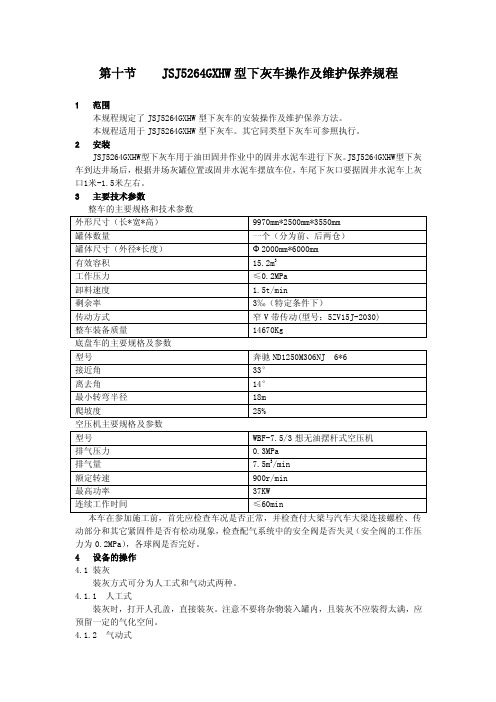
第十节 JSJ5264GXHW型下灰车操作及维护保养规程1 范围本规程规定了JSJ5264GXHW型下灰车的安装操作及维护保养方法。
本规程适用于JSJ5264GXHW型下灰车。
其它同类型下灰车可参照执行。
2 安装JSJ5264GXHW型下灰车用于油田固井作业中的固井水泥车进行下灰。
JSJ5264GXHW型下灰车到达井场后,根据井场灰罐位置或固井水泥车摆放车位,车尾下灰口要据固井水泥车上灰口1米-1.5米左右。
3 主要技术参数整车的主要规格和技术参数底盘车的主要规格及参数动部分和其它紧固件是否有松动现象,检查配气系统中的安全阀是否失灵(安全阀的工作压力为0.2MPa),各球阀是否完好。
4 设备的操作4.1 装灰装灰方式可分为人工式和气动式两种。
4.1.1 人工式装灰时,打开人孔盖,直接装灰。
注意不要将杂物装入罐内,且装灰不应装得太满,应预留一定的气化空间。
4.1.2 气动式由上灰管气动上灰,将备用软管连接贮灰库的卸灰口,打开罐上放空阀,关闭其余阀和人孔口,当放空管排出的空气中带出一定浓度的物料流时,表明罐内物料已装满。
然后关闭上灰蝶阀,上灰完毕。
4.2 卸灰卸灰只从罐内输送卸灰管口。
其具体卸灰方式由用户自灰操作下:4.2.1 确定好卸灰方式后,将上灰口堵上,关闭所有的放空阀、出灰口蝶阀及人孔盖,打开配气系统中的进气阀,一切准备好后,即可进入工作状态。
4.2.2 按底盘说明书的要求启动发动机,怠速运转5分钟后,踩下离合器操纵杆,打开取力器开关,松开离合器操纵杆,将发动机转速调到1200~1500转/分,启动空压机,向罐内进气,待罐内压力达到0.2MPa时,根据对卸灰速度的要求,可前、后仓单独卸灰,也可前、后仓串联卸灰,选择好卸灰型式后,相应地打开前、后仓(或串联管)的卸灰蝶阀即可。
待罐内压力降至0.03MPa时,则表示罐内物料已卸完,此时,先关闭卸料阀,再打开放空阀,再关闭空压机至罐内气压降至零。
至此,下灰完毕。
