电源转换器产品推荐
Murata 86mm 1U 前端 AC-DC 电源转换器 产品说明书

D1U86G-W-460-12-HB3DC D1U86G-W-460-12-HB4DCD1U86G-W-460-12-HxxDC Series 86mm 1U Front End AC-DC Power Supply ConverterFor full details go to/rohs ORDERING GUIDEPart Number Power Output Main Output Standby Output Airfl owD1U86G-W-460-12-HB4DC460W12V12V Back to front D1U86G-W-460-12-HB3DC460W12V12V Front to backINPUT CHARACTERISTICSParameter Conditions Min.Nom.Max.Units Input Voltage Operating Range90115/230264Vac Frequency4750/6063Hz Turn-on Voltage Ramp up818589Vac Turn-off Voltage Ramp down70.574.378 Maximum Input Current (100Vac)460W 5.5Arms Inrush Current At 264Vac at 25°C cold start30Apk Power Factor At 230Vac, full load0.99Effi ciency (230Vac) excluding fan load20% load88%50% load92100% load88OUTPUT VOLTAGE CHARACTERISTICSOutputVoltageParameter Conditions Min.Typ.Max.Units 12VVoltage Set Point1A load12.2712.312.33Vdc Static Regulation11.8512.45Ripple Voltage & Noise120MHz Bandwidth120mV p-pDroop Regulation0.270.30.33VOutput Current038.3ALoad Capacitance22,000μF 12VSBVoltage Set Point11.9712.012.03Vdc Line and Load Regulation11.412.6Ripple Voltage & Noise120MHz Bandwidth120mV p-pOutput Current0 2.5ALoad Capacitance1000μF 1 Ripple and noise are measured with 0.1 μF of ceramic capacitance and 10 μF of tantalum capacitance on each of the power supply outputs. A short coaxial cable with 50Ω scope termination is used.FEATURES⏹460W output power⏹Exceeds 92% effi ciency at 50% load (230Vac Input)⏹12V main output⏹12V standby output of 30W⏹1U height: 3.4" x 7.75" x 1.57"⏹11.1 Watts per cubic inch density⏹N+1 redundancy capable,including hot plugging (up to 8 in parallel)⏹Droop current sharing on 12V main output, ORing FET⏹Overvoltage, overcurrent, overtemperature protection⏹Internal cooling fan (variable speed)⏹PMBus™ / I²C interface with status indicators⏹RoHS compliant PRODUCT OVERVIEWThe D1U86G-W-460-12-HxxDC is a bulk front end power supply which meets the needs of systems requiring high effi ciency distributed power architectures. The output power of this supply is rated at 460W with one main and one standby output. The supply provides high effi ciency performance, hot plug capability, and parallel operation with droop current sharing. Closed-loop internal fan cooling provides reliable long life operation. Industry standard PMBus™ communication protocol makes system integration with this supply seamless and straightforward. The low-profile design and dense packaging makes this supply ideal for delivering reliable, effi cient power to servers, workstations,storage devices and other distributed power systems.CBTest Certifi cateand Test ReportPM/en/3d/acdc.html /en/3d/acdc.html /en/3d/acdc.html /en/3d/acdc.html /en/3d/acdc.html /en/3d/acdc.html Available now at/en/3d/acdc.htmlD1U86G-W-460-12-HxxDC Series86mm 1U Front End AC-DC Power Supply ConverterD1U86G-W-460-12-HxxDC Series86mm 1U Front End AC-DC Power Supply ConverterD1U86G-W-460-12-HxxDC Series86mm 1U Front End AC-DC Power Supply ConverterD1U86G-W-460-12-HxxDC Series86mm 1U Front End AC-DC Power Supply ConverterMurata Power Solutions, Inc. makes no representation that the use of its products in the circuits described herein, or the use of other technical information contained herein, will not infringe upon existing or future patent rights. The descriptions contained herein do not imply the granting of licenses to make, use, or sell equipment constructed in accordance therewith. Specifi cations are subject to change without Murata Power Solutions, Inc. 11 Cabot Boulevard, Mansfi eld, MA 02048-1151 U.S.A.ISO 9001 and 14001 REGISTEREDThis product is subject to the following operating requirementsand the Life and Safety Critical Application Sales Policy: Refer to:/requirements/MECHANICAL DIMENSIONSAC input connector: IEC 320-C143.4"W x 7.75"L x 1.57"H [86.4mm x 196.85mm x 39.9mm]Airfl ow Back to Front Airfl ow Front to BackD1U86G-W-460-12-HB3DC D1U86G-W-460-12-HB4DC。
亿佰特隔离型接口双向转换器E810-DTU(RS)使用手册
目录第一章概述 (2)1.1简介 (2)1.2主要特性 (2)1.3应用场景 (2)第二章产品规格参数 (2)第三章机械尺寸图及标识定义 (3)第四章硬件安装及应用 (4)第五章通信连接示意图 (5)5.1RS232至RS485转换 (5)5.2RS232至RS422转换 (6)第六章故障及排除 (8)6.1数据通信失败 (8)6.2数据丢失或错误 (8)修订历史 (8)关于我们 (8)第一章概述1.1简介E810-DTU(RS)是一款超高性价比RS232-RS485/RS422隔离型接口双向转换器工具。
本产品具有体积小巧、接线简单、方便安装等特点,是工程应用、项目调试及产品开发的可靠助手。
E810-DTU(RS)产品集成1路RS232接口和1路复用RS485/RS422接口,可实现RS232信号与RS485/RS422之间互相透明相互传输。
1.2主要特性●支持RS232与RS485/RS422数据之间双向转换;●波特率自适应;●无需握手信号,实现透明传输;●RS232端口提供浪涌保护,防雷400W保护;●RS485/RS422端口保护,15KV ESD;●RS232与RS485/RS422之间高速光耦信号隔离;●电源隔离电压1500VDC;●支持点到点,点到多点的通信,最多支持32节点;●LED指示电源和信号状态;●5V~36V宽电压电源供电。
1.3应用场景●工业自动化控制系统●公共汽车收费、停车场收费系统●门禁、考勤、一卡通系统●自主银行系统●消费系统等第二章产品规格参数接口方式RS232:DB9孔型连接器RS485/RS422:1*5*3.81,压线方式传输距离1200米(RS485端口);5米(RS232端口)工作温度-40℃~+85℃,工业级工作湿度10%~90%,相对湿度,无冷凝尺寸大小82×84×25mm平均重量130±5g第三章机械尺寸图及标识定义第四章硬件安装及应用安装E810-DTU(RS)隔离型接口双向转换器前请先仔细阅读产品说明书,将产品所适配的通信电缆分别接入RS-232接口端和RS485/RS422接口端,电源适配器接入插口(或接入电源接线端子),本产品采用通用连接器为输入/输出接口,无需跳线设置自动实现RS-485或RS-422通讯方式,可使用双绞线或屏蔽线,连接、拆卸非常方便。
XD312-15-800V超宽电压输入DC-DC降压电源转换器模块手册
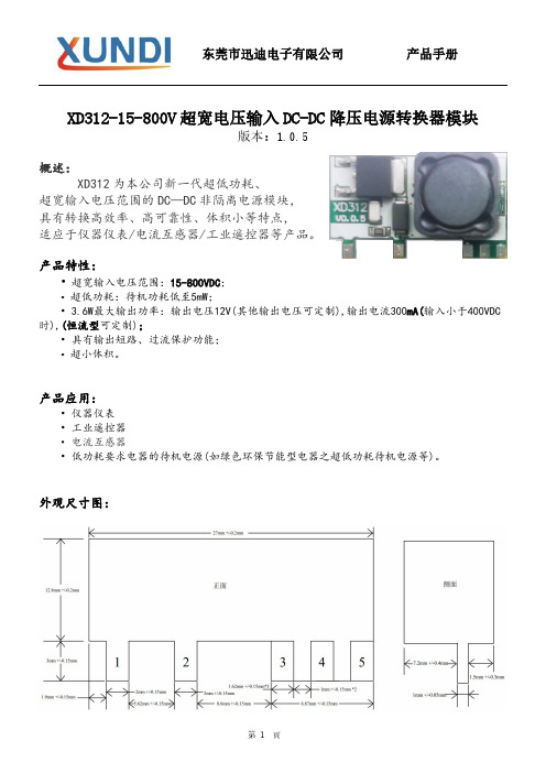
XD312-15-800V超宽电压输入DC-DC降压电源转换器模块版本:1.0.5概述:XD312为本公司新一代超低功耗、超宽输入电压范围的DC—DC非隔离电源模块,具有转换高效率、高可靠性、体积小等特点,适应于仪器仪表/电流互感器/工业遥控器等产品。
产品特性:•超宽输入电压范围:15-800VDC;•超低功耗:待机功耗低至5mW;• 3.6W最大输出功率:输出电压12V(其他输出电压可定制),输出电流300mA(输入小于400VDC 时),(恒流型可定制);•具有输出短路、过流保护功能;•超小体积。
产品应用:•仪器仪表•工业遥控器•电流互感器•低功耗要求电器的待机电源(如绿色环保节能型电器之超低功耗待机电源等)。
外观尺寸图:引脚编号名称功能描述1VIN-负电源输入脚2VIN+正电源输入脚3VOUT+正电源输出脚4CIN外接电容到3脚(VOUT+) 5VOUT-负电源输出脚说明:实际应用中超过上述极限值可能会导致电源模块的永久性损坏。
电气参数:注:1.在输入电压小于模块设定输出电压时,那么模块会以直通模式输出,输出100mA 时,压差0.8V左右;输出250mA时,压差2V左右。
2.上述参数值为常温环境测试下的典型值,实际应用中因工作环境不同可能有所差异。
3.如使用环境温度过高,输出电流需降额使用,具体以实际测试为准。
注:1.C1,C2容量串联后最少需大于2uF,耐压值串联后也应大于输入电压。
当输入处于交流宽范围供电(如AC18~AC400)时,C1,C2建议取10uF及以上。
2.C3取值:输入处于交流宽范围供电(如AC18~AC400)时,C3使用470uF;纯直流供电(如电瓶等)取100uF至220uF即可。
3.D1耐压需大于输入电压。
警告:因该模块为高压供电电源模块,其中将涉及到高电压,为了你的人身与设备安全,在上电调试过程中建议使用交流隔离电源来供电!。
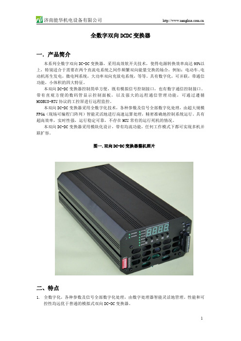
双向DCDC直流变换器,直流变换电源,直流升压降压转换器
1.3 – 4.0
< 1mS < 0.5S
5KW 6KW 0-25A(外输入电压控制) 1-10A(数码管设置) 200V–450V 可调,误差±2% 400V–800V 可调,误差±2% 2 A/V < 2% < 1V < 5%
6
济南能华机电设备有限公司
本双向 DC-DC 变换器采用模块化设计,带有均流功能,任何工作模式下都可实现多机并 联扩容。
图一.双向 DC-DC 变换器整机照片
二、特点
1. 全数字化,各种参数及信号全部数字化处理,由数字处理器智能灵活地管理。性能和可 控性均远优于普通的模拟式双向 DC-DC 变换器。
1
济南能华机电设备有限公司
PDn 为降压模式控制信号输入端,当 PDn 输入 3.3V ~5V 的高电平,并且 PUp 为低电平 时,双向逆变器为降压工作模式,电流从高压端子 IFHV 流入,经变换器变换为低压后,从 低压端子 IFLV 输出。
PUp 为升压模式控制信号输入端,当 PUp 输入 3.3V ~5V 的高电平,并且 PDn 为低电平 时,双向逆变器为升压工作模式,电流从低压端子 IFLV 流入,经变换器变换为高压后,从 高压端子 LFHV 输出。
> 95% < 12W < 20W 温控风冷 -25℃ - 60℃ 80℃
28A
15A
√ 5S
5S
315mm X140mm X 85mm 2.5Kg
八.产品图片
7
济南能华机电设备有限公司 图十.模块线路板照片(正面)
图十.模块线路板照片(反面)
图十一.模块接线图
在恒流模式时,Iout 总是正值(忽略电流源等效内阻消耗)。 图七. DC-DC 变换器恒流模式等效电路模型
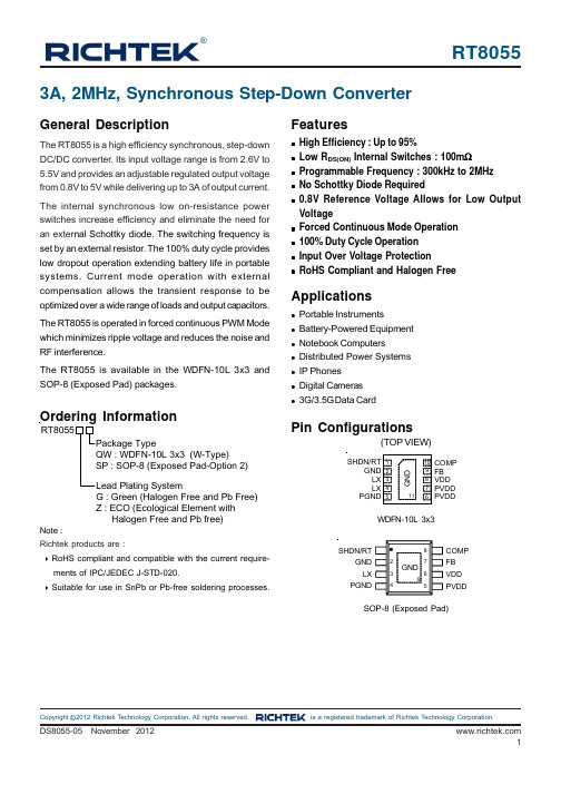
Richtek技术公司产品说明书:RT8055高效同步步下电源转换器
RT8055®©Copyright 2012 Richtek Technology Corporation. All rights reserved. is a registered trademark of Richtek Technology Corporation.Featuresz High Efficiency : Up to 95%z Low R DS(ON) Internal Switches : 100m Ωz Programmable Frequency : 300kHz to 2MHz z No Schottky Diode Requiredz0.8V Reference Voltage Allows for Low Output Voltagez Forced Continuous Mode Operation z 100% Duty Cycle Operation z Input Over Voltage ProtectionzRoHS Compliant and Halogen FreeApplicationsz Portable Instrumentsz Battery-Powered Equipment z Notebook Computersz Distributed Power Systems z IP Phonesz Digital Cameras z3G/3.5G Data CardGeneral DescriptionThe RT8055 is a high efficiency synchronous, step-down DC/DC converter. Its input voltage range is from 2.6V to 5.5V and provides an adjustable regulated output voltage from 0.8V to 5V while delivering up to 3A of output current.The internal synchronous low on-resistance power switches increase efficiency and eliminate the need for an exter nal Schottky diode. The switching frequency is set by an external resistor. The 100% duty cycle provides low dropout operation extending battery life in portable systems. Current mode operation with external compensation allows the transient response to be optimized over a wide range of loads and output capacitors.The RT8055 is operated in forced continuous PWM Mode which minimizes ripple voltage and reduces the noise and RF interference.The RT8055 is available in the WDFN-10L 3x3 and SOP-8 (Exposed Pad) packages.Ordering InformationPin Configurations(TOP VIEW)WDFN-10L 3x33A, 2MHz, Synchronous Step-Down ConverterNote :Richtek products are :` RoHS compliant and compatible with the current require-ments of IPC/JEDEC J-STD-020.` Suitable for use in SnPb or Pb-free soldering processes.COMP FB VDD PVDDPVDDSHDN/RTGND LX PGNDCOMP FB PVDDVDD SOP-8 (Exposed Pad)G : Green (Halogen Free and Pb Free)Z : ECO (Ecological Element with Halogen Free and Pb free)RT8055©Copyright 2012 Richtek Technology Corporation. All rights reserved. is a registered trademark of Richtek Technology Corporation.Typical Application CircuitTable 1. Recommended Component SelectionV OUT Marking InformationJN= : Product Code YMDNN : Date CodeRT8055GQWRT8055GSPRT8055GSP : Product NumberYMDNN : Date CodeJN : Product Code YMDNN : Date CodeRT8055ZQWRT8055©Copyright 2012 Richtek Technology Corporation. All rights reserved. is a registered trademark of Richtek Technology Corporation.Function Block DiagramRT8055©Copyright 2012 Richtek Technology Corporation. All rights reserved. is a registered trademark of Richtek Technology Corporation.Absolute Maximum Ratings (Note 1)zSupply Input Voltage, VDD, PVDD ----------------------------------------------------------------------------−0.3V to 6.5Vz LX Pin Switch Voltage --------------------------------------------------------------------------------------------−0.3V to (PVDD + 0.3V)<10ns ----------------------------------------------------------------------------------------------------------------−5V to 8.5V z Other I/O Pin Voltages -------------------------------------------------------------------------------------------−0.3V to 6.5V z LX Pin Switch Current --------------------------------------------------------------------------------------------4A z Power Dissipation, P D @ T A = 25°CWDFN-10L 3x3-----------------------------------------------------------------------------------------------------1.667W SOP-8 (Exposed Pad)-------------------------------------------------------------------------------------------1.333W z Package Thermal Resistance (Note 2)WDFN-10L 3x3, θJA -----------------------------------------------------------------------------------------------60°C/W WDFN-10L 3x3, θJC -----------------------------------------------------------------------------------------------7.8°C/W SOP-8 (Exposed Pad), θJA -------------------------------------------------------------------------------------75°C/W SOP-8 (Exposed Pad), θJC -------------------------------------------------------------------------------------15°C/W z Junction T emperature ---------------------------------------------------------------------------------------------150°C z Lead Temperature (Soldering, 10 sec.)-----------------------------------------------------------------------260°C z Storage T emperature Range ------------------------------------------------------------------------------------−65°C to 150°C z ESD Susceptibility (Note 3)HBM (Human Body Model)--------------------------------------------------------------------------------------2kVElectrical Characteristics(V DD = 3.3V, T A= 25°C, unless otherwise specified)Recommended Operating Conditions (Note 4)z Supply Input Voltage ----------------------------------------------------------------------------------------------2.6V to 5.5V z Junction T emperature Range ------------------------------------------------------------------------------------ −40°C to 125°C zAmbient T emperature Range ------------------------------------------------------------------------------------ −40°C to 85°CRT8055©Copyright 2012 Richtek Technology Corporation. All rights reserved. is a registered trademark of Richtek Technology Corporation.Note 1. Stresses beyond those listed “Absolute Maximum Ratings ” may cause permanent damage to the device. These arestress ratings only, and functional operation of the device at these or any other conditions beyond those indicated in the operational sections of the specifications is not implied. Exposure to absolute maximum rating conditions may affect device reliability.Note 2. θJA is measured at T A = 25°C on a high effective thermal conductivity four-layer test board per JEDEC 51-7. θJC ismeasured at the exposed pad of the package.Note 3. Devices are ESD sensitive. Handling precaution is recommended.Note 4. The device is not guaranteed to function outside its operating conditions.Note 5. Guaranteed by design.RT8055©Copyright 2012 Richtek Technology Corporation. All rights reserved. is a registered trademark of Richtek Technology Corporation.Typical Operating CharacteristicsOutput Voltage vs. Input Voltage3.303.313.323.333.343.353.363.53.73.94.14.34.54.74.95.15.35.5Input Voltage (V)O u t p u t V o l t a g e (V)Output Voltage vs. Output Current3.263.273.283.293.303.313.323.333.343.353.363.373.380.00.30.60.91.21.51.82.12.42.73.0Output Current (A)O u t p u t V o l t a g e (V)Efficiency vs. Output Current01020304050607080901000.00.30.60.91.21.51.82.12.42.73.0Output Current (A)E f f i c i e n c y (%)Switching Frequency vs. Temperature1.51.61.71.81.92.02.1-50-25255075100125Temperature (°C)S w i t c h i n g F r e q u e n c y (M H z )Switching Frequency vs. Input Voltage1.51.61.71.81.92.02.13.53.73.94.14.34.54.74.95.15.35.5Input Voltage (V)S w i t c h i n g F r e q u e n c y (M H z )V IN UVLO vs. Temperature2.002.052.102.152.202.252.302.352.402.452.50-50-25255075100125Temperature (°C)V I N U V L O (V )RT8055©Copyright 2012 Richtek Technology Corporation. All rights reserved. is a registered trademark of Richtek Technology Corporation.Output RippleTime (500ns/Div)V IN = 5V, V OUT = 3.3V I OUT = 0AV LX (5V/Div)V OUT (5mV/Div)Output Ripple Time (500ns/Div)V IN = 5V, V OUT = 3.3V I OUT = 3A V LX (5V/Div)V OUT(5mV/Div)Reference Voltage vs. Temperature0.7600.7680.7760.7840.7920.8000.8080.8160.8240.8320.840-50-25255075100125Temperature (°C)R e f e r e n c e V o l t a g e (V )Output Current Limit vs. Temperature2.02.53.03.54.04.55.05.56.0-50-25255075100125Temperature (°C)O u t p u t C u r r e n t L i m i t (A)Output Current Limit vs. Input Voltage2.02.53.03.54.04.55.05.56.03.53.73.94.14.34.54.74.95.15.35.5Input Voltage (V)O u t p u t C u r r e n t L i m i t (A)Output Voltage vs. Temperature3.203.223.243.263.283.303.323.343.363.383.40-50-25255075100125Temperature (°C)O u t p u t V o l t a g e (V)RT8055©Copyright 2012 Richtek Technology Corporation. All rights reserved. is a registered trademark of Richtek Technology Corporation.Power On from V INTime (1ms/Div)V IN = 5V, V OUT = 3.3V I OUT = 0AV LX (5V/Div)V IN (2V/Div)V OUT (1V/Div)Load Transient ResponseTime (100μs/Div)I OUT (1A/Div)V OUT(200mV/Div)V IN = 5V, V OUT = 3.3V I OUT = 0A to 2ALoad Transient ResponseTime (100μs/Div)I OUT (1A/Div)V OUT(200mV/Div)V IN = 5V, V OUT = 3.3V I OUT = 0A to 3AUVP ShutdownTime (10μs/Div)V LX (5V/Div)V OUT (1V/Div)V IN = 5V, V OUT = 3.3VRT8055©Copyright 2012 Richtek Technology Corporation. All rights reserved. is a registered trademark of Richtek Technology Corporation.Application InformationThe basic RT8055 application circuit is shown in TypicalApplication Circuit. External component selection is determined by the maximum load current and begins with the selection of the inductor value and operating frequency followed by C IN and C OUT .Output Voltage SettingThe output voltage is set by an external resistive divider according to the following equation :Figure 1. Setting the Output Voltage⎟⎠⎞⎜⎝⎛+×=R2R11V V REF OUT Soft-StartThe RT8055 contains an internal soft-start clamp that gradually raises the clamp on the COMP pin.Operating FrequencySelection of the operating frequency is a tradeoff between efficiency and component size. High frequency operation allows the use of smaller inductor and capacitor values.Operation at lower frequency improves efficiency by reducing internal gate charge and switching losses but requires larger inductance and/or capacitance to maintain low output ripple voltage.The operating frequency of the RT8055 is determined by an external resistor that is connected between the SHDN/RT pin and GND. The value of the resistor sets the ramp current that is used to charge and discharge an internal timing capacitor within the oscillator. The RT resistor value can be determined by examining the frequency vs. R RT curve. Although frequencies as high as 2MHz are possible,the minimum on-time of the RT8055 imposes a minimum limit on the operating duty cycle. The minimum on-time is typically 110ns. Therefore, the minimum duty cycle is equal to 100 x 110ns x f (Hz).Figure 2100% Duty Cycle OperationWhen the input supply voltage decreases toward the outputvoltage, the duty cycle increases toward the maximum on-time. Further reduction of the supply voltage forces the main switch to remain on for more than one cycle eventually reaching 100% duty cycle.The output voltage will then be determined by the input voltage minus the voltage drop across the internal P-MOSFET and the inductor.Low Supply OperationThe RT8055 is designed to operate down to an input supply voltage of 2.6V. One important consideration at low input supply voltages is that the R DS(ON) of the P-Channel and N-Channel power switches increases. The user should calculate the power dissipation when the RT8055 is used at 100% duty cycle with low input voltages to ensure that thermal limits are not exceeded.Slope Compensation and Inductor Peak Current Slope compensation provides stability in constant frequency architectures by preventing sub-harmonic oscillations at duty cycles greater than 50%. It is accomplished internally by adding a compensating ramp to the inductor current signal. Normally, the maximum inductor peak current is reduced when slope compensation is added. In the RT8055, however, separated inductor current signals are used to monitor over current condition.0.00.51.01.52.02.53.002004006008001000R OSC (K )S w i t c h i n g F r e q u e n c y (M H z )(k Ω)where V REF equals to 0.8V typical.The resistive divider allows the FB pin to sense a fraction of the output voltage as shown in Figure 1.RT8055©Copyright 2012 Richtek Technology Corporation. All rights reserved. is a registered trademark of Richtek Technology Corporation.This formula has a maximum at V IN = 2V OUT , where I RMS = I OUT /2. This simple worst-case condition is commonly used for design because even significant deviations do not offer much relief. Choose a capacitor rated at a higher temperature than required.Several capacitors may also be paralleled to meet size or height requirements in the design.The selection of C OUT is determined by the effective series resistance (ESR) that is required to minimize voltage ripple and load step transients, as well as the amount of bulk capacitance that is necessary to ensure that the control loop is stable. Loop stability can be checked by viewing the load transient response as described in a later section.The output ripple, ΔV OUT , is determined by :1V V V V I I OUTININ OUT OUT(MAX)RMS −=⎦⎤⎢⎣⎡+Δ≤ΔOUT L OUT 8fC 1ESR I V This keeps the maximum output current relatively constant regardless of duty cycle.Short Circuit ProtectionWhen the output is shorted to ground, the inductor current decays very slowly during a single switching cycle. A current runaway detector is used to monitor inductor current. As current increasing beyond the control of current loop, switching cycles will be skipped to prevent current runaway from occurring.Inductor SelectionThe inductor value and operating frequency determine the ripple current according to a specific input and output voltage. The ripple current ΔI L increases with higher V IN and decreases with higher inductance.OUT OUT L IN V V I =1f L V ⎡⎤⎡⎤Δ×−⎢⎥⎢⎥×⎣⎦⎣⎦OUT OUT L(MAX)IN(MAX)V V L =1f I V ⎡⎤⎡⎤×−⎢⎥⎢×Δ⎣⎦⎣⎦Having a lower ripple current reduces not only the ESR losses in the output capacitors but also the output voltage ripple. However, it requires a large inductor to achieve this goal.For the ripple current selection, the val ue of ΔI L = 0.4(I MAX )will be a reasonable starting point. The large st ripple current occurs at the highest V IN . To guarantee that the ripple current stays below the specified maximum, the inductor value should be chosen according to the following equation :The inductor's current rating (caused a 40°C temperature rising from 25°C ambient) should be greater than the maximum load current and its saturation current should be greater than the short circuit peak current limit.C IN and C OUT SelectionThe input capacitance, C IN , is needed to filter the trapezoidal current at the source of the top MOSFET . To prevent large ripple voltage, a low ESR input capacitor sized for the maximum RMS current should be used. RMS current is given by :The output ripple is highest at maximum input voltagesince ΔI L increases with input voltage. Multiple capacitors placed in parallel may be needed to meet the ESR and RMS current handling requirements. Dry tantalum, special polymer, aluminum electrolytic and ceramic capacitors are all available in surface mount packages. Special polymer capacitors offer very low ESR but have lower capacitance density than other types. Tantalum capacitors have the highest capacitance density but it is important to only use types that have been surge tested for use in switching power supplies. Aluminum electrolytic capacitors have significantly higher ESR but can be used in cost-sensitive applications provided that consideration is given to ripple current ratings and long term reliability. Ceramic capacitors have excellent low ESR characteristics but can have a high voltage coefficient and audible piezoelectric effects.The high Q of ceramic capacitors with trace inductance can also lead to significant ringing.Using Ceramic Input and Output CapacitorsHigher values, lower cost ceramic capacitors are now becoming available in smaller case sizes. Their high ripple current, high voltage rating and low ESR make them ideal for switching regulator applications. However, care must be taken when these capacitors are used at the input and output. When a ceramic capacitor is used at the inputDS8055-05 November 2012©Copyright 2012 Richtek Technology Corporation. All rights reserved. is a registered trademark of Richtek Technology Corporation.and the power is supplied by a wall adapter through long wires, a load step at the output can induce ringing at the input, V DD . At best, this ringing can couple to the output and be mistaken as loop instability. At worst, a sudden inrush of current through the long wires can potentially cause a voltage spike at V IN large enough to damage the part.Thermal ConsiderationsFor continuous operation, do not exceed absolute maximum junction temperature. The maximum power dissipation depends on the thermal resistance of the IC package, PCB layout, rate of surrounding airflow, and difference between junction and ambient temperature. The maximum power dissipation can be calculated by the following formula :P D(MAX) = (T J(MAX) − T A ) / θJAwhere T J(MAX) is the maximum junction temperature, T A is the ambient temperature, and θJA is the junction to ambient thermal resistance.For recommended operating condition specifications, the maximum junction temperature is 125°C. The junction to ambient thermal resistance, θJA , is layout dependent. For SOP-8 (Exposed Pad) packages, the thermal resistance,θJA , is 75°C/W on a standard JEDEC 51-7 four-layer thermal test board. For WDFN-10L 3x3 packages, the thermal resistance, θJA , is 70°C/W on a standard JEDEC 51-7 four-layer thermal test board. The maximum power dissipation at T A = 25°C can be calculated by the following formulas :P D(MAX) = (125°C − 25°C) / (75°C/W) = 1.333W for SOP-8 (Exposed Pad) packageP D(MAX) = (125°C − 25°C) / (70°C/W) = 1.429W for WDFN-10L 3x3 packageThe maximum power dissipation depends on the operating ambient temperature for fixed T J(MAX) and thermal resistance, θJA . The derating curves in Figure 3 allow the designer to see the effect of rising ambient temperature on the maximum power dissipation.Figure 3. Derating Curve of Maximum Power Dissipation Layout ConsiderationsFollow the PCB layout guidelines for optimal performance of RT8055.`A ground plane is recommended. If a ground plane layer is not used, the signal and power grounds should be segregated with all small-signal components returning to the GND pin at one point that is then connected to the PGND pin close to the IC. The exposed pad should be connected to GND.`Connect the terminal of the input capacitor(s), C IN , as close as possible to the PVDD pin. This capacitor provides the AC current into the internal power MOSFETs.`LX node is with high frequency voltage swing and should be kept within small area. Keep all sensitive small-signal nodes away from the LX node to prevent stray capacitive noise pick-up.`Flood all unused areas on all layers with copper.Flooding with copper will reduce the temperature rise of powercomponents.You can connect the copper areas to any DC net (PVDD,VDD, VOUT , PGND, GND, or any other DC rail in your system).`Connect the FB pin directly to the feedback resistors.The resistor divider must be connected between V OUT and GND.0.00.10.20.30.40.50.60.70.80.91.01.11.21.31.41.50255075100125Ambient Temperature (°C)M a x i m u m P o w e r D i s s i p a t i o n (W )©Copyright 2012 Richtek Technology Corporation. All rights reserved. is a registered trademark of Richtek Technology Corporation.Table 3. Capacitors for C and C Recommended component selection for Typical ApplicationFigure 4. PCB Layout GuideFand GND as closer as possibleLX should befrom this tracenear RT8055Connect the FB pin directly to feedback resistors. TheDS8055-05 November 2012©Copyright 2012 Richtek Technology Corporation. All rights reserved. is a registered trademark of Richtek Technology Corporation.W-Type 10L DFN 3x3 PackageRichtek Technology Corporation5F, No. 20, Taiyuen Street, Chupei City Hsinchu, Taiwan, R.O.C.Tel: (8863)5526789Richtek products are sold by description only. Richtek reserves the right to change the circuitry and/or specifications without notice at any time. Customers shouldobtain the latest relevant information and data sheets before placing orders and should verify that such information is current and complete. Richtek cannot assume responsibility for use of any circuitry other than circuitry entirely embodied in a Richtek product. Information furnished by Richtek is believed to be accurate and reliable. However, no responsibility is assumed by Richtek or its subsidiaries for its use; nor for any infringements of patents or other rights of third parties which may result from its use. No license is granted by implication or otherwise under any patent or patent rights of Richtek or its subsidiaries.HM(Bottom of Package)8-Lead SOP (Exposed Pad) Plastic Package。
常用开关电源芯片大全
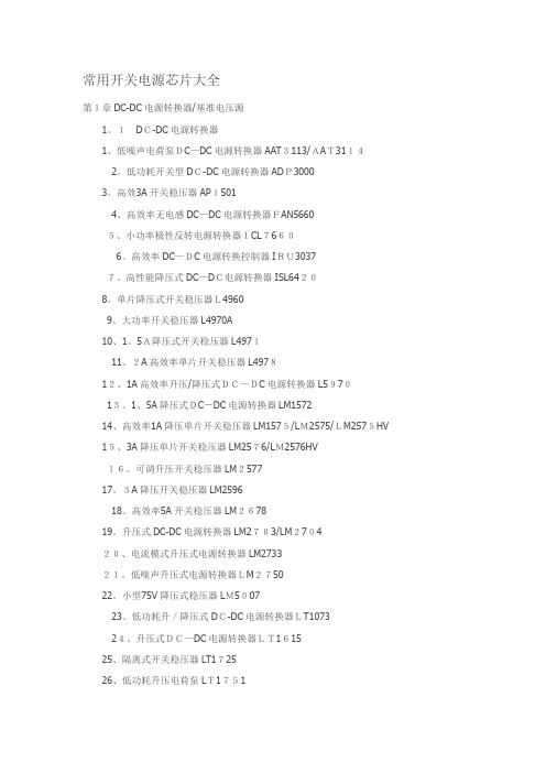
常用开关电源芯片大全第1章DC-DC电源转换器/基准电压源1。
1DC-DC电源转换器1、低噪声电荷泵DC—DC电源转换器AAT3113/AAT31142。
低功耗开关型DC-DC电源转换器ADP30003。
高效3A开关稳压器AP15014、高效率无电感DC—DC电源转换器FAN56605、小功率极性反转电源转换器ICL76606。
高效率DC—DC电源转换控制器IRU30377、高性能降压式DC—DC电源转换器ISL64208。
单片降压式开关稳压器L49609、大功率开关稳压器L4970A10、1。
5A降压式开关稳压器L497111。
2A高效率单片开关稳压器L497812、1A高效率升压/降压式DC—DC电源转换器L597013。
1、5A降压式DC-DC电源转换器LM157214、高效率1A降压单片开关稳压器LM1575/LM2575/LM2575HV15、3A降压单片开关稳压器LM2576/LM2576HV16。
可调升压开关稳压器LM257717。
3A降压开关稳压器LM259618、高效率5A开关稳压器LM267819。
升压式DC-DC电源转换器LM2703/LM270420、电流模式升压式电源转换器LM273321。
低噪声升压式电源转换器LM275022。
小型75V降压式稳压器LM500723、低功耗升/降压式DC-DC电源转换器LT107324、升压式DC—DC电源转换器LT161525、隔离式开关稳压器LT172526、低功耗升压电荷泵LT175127、大电流高频降压式DC—DC电源转换器LT176528、大电流升压转换器LT193529、高效升压式电荷泵LT193730。
高压输入降压式电源转换器LT195631。
1。
5A升压式电源转换器LT196132、高压升/降压式电源转换器LT343333。
单片3A升压式DC—DC电源转换器LT343634、通用升压式DC-DC电源转换器LT346035、高效率低功耗升压式电源转换器LT346436、1。
网络变压器品牌
网络变压器品牌一、引言网络变压器是一种用于网络设备的电源设备,用于将电源输入转换为适合网络设备使用的电压输出。
随着网络设备的普及和应用范围的扩大,网络变压器的需求也越来越大。
本文将介绍几个知名的网络变压器品牌,包括其品牌背景、产品特点和市场口碑等方面的信息。
二、品牌一:ABC网络变压器1. 品牌背景ABC网络变压器是一家专注于网络设备电源领域的知名品牌。
成立于2000年,公司总部位于国内某大城市,拥有一支专业的研发团队和先进的生产设备。
2. 产品特点ABC网络变压器的产品具有以下特点:- 高效节能:采用先进的能效技术,能够将电能转换效率提高至90%以上,节约能源。
- 稳定可靠:采用优质的电子元件和材料,具有良好的稳定性和可靠性,能够在长时间使用中保持稳定的输出电压。
- 多功能设计:支持多种输入和输出电压规格,适应不同的网络设备需求。
- 安全防护:具备过载保护、短路保护、过压保护等多重安全保护功能,保障网络设备的安全运行。
3. 市场口碑ABC网络变压器在市场上具有良好的口碑,得到了广大用户的认可和信赖。
用户普遍认为其产品质量优良,性能稳定可靠,能够满足各种网络设备的需求。
三、品牌二:XYZ网络变压器1. 品牌背景XYZ网络变压器是一家国际知名的网络设备电源供应商。
公司成立于1995年,总部位于国外某大城市,拥有全球范围的销售网络和强大的研发实力。
2. 产品特点XYZ网络变压器的产品具有以下特点:- 高效节能:采用先进的能效管理技术,能够实现高达95%以上的电能转换效率,节约能源。
- 高密度设计:采用先进的封装技术和散热设计,使得产品具有更小的体积和更高的功率密度。
- 远程监控:支持远程监控和管理功能,可以通过网络对变压器进行实时监控和故障排查。
- 兼容性强:支持多种输入和输出电压规格,适用于各种网络设备的接入。
3. 市场口碑XYZ网络变压器在全球范围内有着广泛的市场份额,其产品被广大用户认可为高品质的网络变压器。
0-2000A5V交流恒流源

∙功能: 电源转换器∙品牌: 能华产品简介:交流恒流源是一种宽频谱,高精度稳流,低谐波、失真的稳流电流源。
本恒流源是在外界电网电源产生波动或用电符合阻抗特性发生变化时仍能使输出电流保持恒定的交流电源。
该电源主要应用在进行特定电流热效应应用和测试的产品和场所。
如断路器、熔断器、热继电器、磁力启动器、线圈等需要实验。
产品特点:1、交流恒流源是为低压电器用户专门设计制造的,其输出电流是恒定的,输出波形为纯正弦波,可作为检测过流实验仪器。
2、本交流恒流源可带阻性、感性、容性负载,满足低压电器对测试电源的要求。
3、突出的优点,稳流精度高,可根据用户使用环境有1%,0.8%,0.5%,0.3%级别。
保证输出电流恒定。
此前使用的大电流发生器方案由于温度变化,导线、接头和线圈的铜阻等一直在变化,4、操作人员须经常调节调压器来恒定电流,费时费精力,而且精度是无法与本电源相比的,低压电器生产中,须对电流进行校验、老化的项目上,使用本电源是目前最佳选择,如热继电器动作电流的整定,空气开关热脱扣电流的测量等。
5、可进行不同电流等级的自动化测试(项目:电压、电流、频率、升降时间,可循环测试操作)6、频率可调范围:40-500HZ(选配),固定输出:50HZ、60HZ(更多范围内固定输出频率可根据用户需求设计)7、可为用户设置模拟量(信号)控制或RS232、RS485上位机通信控制产品应用:◆交流空气开关◆交流接触器◆机械开关,电子开关◆交流互感器◆热继电器、塑壳断路器、小型短路器及需要设定额定电流、动作电流、短路保护电流等◆自动化检测校验台◆电流要求测试场所工作原理:采用SPWM高频调制的方式,模拟成线性电抗器,与变流器串联而成,控制电路为线性电路与数字电路的阻合。
利用进口高精度真有效值转换器将输出电流转换成直流电压信号,与精密基准电压相比较,高精度运放组成P-I调节器,控制主回骆的阻抗,来达到恒流的目的,大功率开关采用进口IGBT模块,具有效率高,无噪音,波形好的优点,在使用中,允许负载突然开路或短路,流水线与快校台使用尤感方便。
XL7035 XL7035E1降压型直流电源变换器芯片(高电压型)
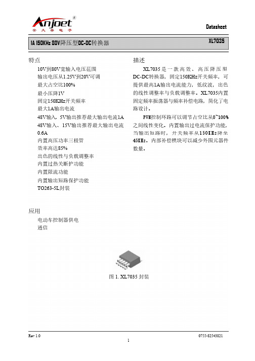
Datasheet XL7035
Symbol
A B C C2 D E e F L L2
Dimensions In Millimeters
Min
Max
4.440
4.650
0.710
0.970
0.360
0.640
1.255
1.285
8.390
8.890
9.960
10.360
1.550
0.0 -0.5 -1.0
-1.5
-2.0
-2.5
-3.0
-50
-25
0
25
50
75
Temperature(℃)
100
125
图 6. 反馈电压变化曲线
Datasheet XL7035
Rev 1.0
0755-82543821 6
XLSEMI
1A 150KHz 80V降压型DC-DC转换器 系统典型应用 (VOUT=15V/0.6A)
Rev 1.0
0755-82543821 7
XLSEMI
1A 150KHz 80V降压型DC-DC转换器 系统典型应用(VOUT=5V/1A)
Datasheet XL7035
图 9. XL7035 系统参数测量电路(VIN=10V~80V, VOUT=5V/1A)
Efficiency VS Output current
Datasheet XL7035
图 7. XL7035 系统参数测量电路 (VIN=20V~80V, VOUT=15V/0.6A)
Efficiency VS Output current
95
90
XL40155A降压型直流电源变换器芯片(大功率型)
XL4015 5A 降压型直流电源变换器芯片(大功率型 )XL4015 5A 降压型直流电源变换器芯片(大功率型 ) 产品名称: XL4015 5A 降压型直流电源变换器芯片(大功率型 ) 产品型号: XL4015 产品展商:深圳劲锐佳科技有限公司产品文档:无相关文档简单介绍 XL4015 5A 降压型直流电源变换器芯片 (大功率型 ) 1、最大输出电流:5A ;2、最高输入电压: XL4015 为 8~36V 3 、输出电压: ADJ (0.8V) 可调; 4、振动频率: 180kHz ;5、转换效率: 85%~ 95%(不同电压输出时的效率不同);6、控制方式: PWM ;7、工作温度范围: -40℃~ +125℃ 8、工作模式:低功耗/正常两种模式可外部控制; XL4015 5A 降压型直流电源变换器芯片 (大功率型 )1、最大输出电流: 5A ;2、最高输入电压: XL4015 为8~36V3 、输出电压: ADJ (0.8V) 可调;4、振动频率:160kHz ;5、转换效率: 85%~ 95%(不同电压输出时的效率不同);6、控制方式: PWM ; 7、工作温度范围: -40℃~+125℃ 8、工作模式:低功耗 /正常两种模式可外部控制; 9、工作模式控制: TTL 电平兼容; 10、所需外部元件:只需极少的外围器件便可构成高效稳压电路;外围元件少,低纹波。
输入 25V电压,输出 12V 情况下,效率可达到 95%。
12、器件保护:热关断及电流限 ,输出短路保护功能;输入电源开关噪声抑制功能;Enanle 开关信号的迟滞功能;技术特点 (功能兼容 )---AOZ1014,LM2677,LM2678,LM2679 (1)全内置型单片高电压、高频率、高效率、大电流、高可靠性、高性价比集成电路;(2)系统设计简单、方便灵活、高功率密度;( 3)常规的过流保护,过热保护,输出短路保护都内置;(4)高效率,在输入电压 20V-30V ,输出功率 50W 时效率高达90%以上。
网络变压器品牌
网络变压器品牌网络变压器品牌是指在网络设备中用于提供稳定电压的一种电子设备。
它可以将输入电压调整为适合网络设备使用的稳定输出电压,以保护网络设备免受电压波动的影响。
在市场上,有许多知名的网络变压器品牌,它们以其高品质、可靠性和卓越的性能而闻名。
以下是几个常见的网络变压器品牌:1. Cisco:作为全球领先的网络解决方案提供商,Cisco提供了一系列高质量的网络变压器产品。
其产品具有出色的性能和可靠性,广泛应用于企业级网络设备中。
2. Schneider Electric:作为一家全球领先的能源管理和自动化解决方案提供商,Schneider Electric也提供了高品质的网络变压器产品。
其产品具有先进的技术和可靠的性能,适用于各种网络设备。
3. Tripp Lite:作为一家专注于电源和连接解决方案的公司,Tripp Lite提供了一系列高性能的网络变压器产品。
其产品具有紧凑、高效和可靠的特点,适用于小型和中型网络设备。
4. APC:作为施耐德电气集团旗下的品牌,APC提供了一系列高质量的网络变压器产品。
其产品具有先进的技术和可靠的性能,广泛应用于数据中心和企业级网络设备中。
5. Eaton:作为一家全球领先的电力管理公司,Eaton提供了一系列高性能的网络变压器产品。
其产品具有高效、可靠和节能的特点,适用于各种网络设备。
除了上述品牌,市场上还有许多其他品牌提供网络变压器产品,如Delta、Emerson、APC等。
在选择网络变压器品牌时,可以根据自己的需求和预算来进行选择。
同时,建议参考用户评价和专业评测,以了解不同品牌的产品性能和可靠性。
总之,网络变压器品牌众多,每个品牌都有其独特的特点和优势。
通过选择合适的品牌和产品,可以保证网络设备的稳定运行和长期可靠性。
超强智能离线开关电源转换器VIPerPlus系列(ST)
超强智能离线开关电源转换器VIPerPlus系列(ST)VIPerPlus系列离线开关电源(SMPS)转换器适用于以全球各类市电为主电源的节能型电源供应,包括咖啡机、洗衣机和洗碗机等家电的电源,液晶电视、DVD播放机和机顶盒等消费电子设备的电源,家居和建筑照明的电源,台式个人电脑和服务器的辅助电源,手机、数码相机、便携音频播放器、玩具和无绳家电(如剃须刀)的充电器。
VIPerPlus全系列产品均以一个封装内集成控制器、启动电路和一个800V 抗雪崩的功率MOSFET。
新的集成功能和高击穿电压有助于提高电源的耐用性和可靠性,减少外部元器件的数量,提供更高的工作能效和超低的待机功耗,在265V时待机功耗小于50mW;如果优化变压器设计,待机功耗可更降低至30mW。
其中的800V抗雪崩功率MOSFET是专门为VIPerPlus系列产品优化的。
固定频率PWM控制器具有频率抖动技术,采用创新的准谐振拓扑,在最大化工作能效的同时,还能降低EMI滤波器成本。
VIPerPlus系列拥有同类产品中最好的待机功耗,使客户的产品可以符合最严格的节能法规(能源之星、80+ 铜级、银级、金级认证),VIPerPlus系列的保护功能包括精确的可调过压和超载保护、滞后过热保护、两级过流保护和开环失效断开保护。
通过集成一个高压启动电流发生器,以及用于转换器启动阶段的基本漏极电流控制功能,VIPerPlus不再需要启动电阻,可降低次二极管上的压力,并可以防止变压器饱和。
产品内嵌的SenseFET节省了外部的感应元器件,使其拥有精确的漏极电流极限值。
故障检测电路可激活转换器的自动重启功能,以防止浪涌对电源或负载造成损坏。
VIPerPlus全系列产品都已量产,采用DIP-7或SO16N封装。
转换电源变压器TS系列参数说明
转换电源变压器TS系列参数说明:
由于世界各国及地区的电力环境不同,民用电压也存在差异,各国电器的电压适用范围也不同;TS系列电压转换变压器是专门为进口电器设备配套设计是一种理想的电源,可连续工作。
适用于各种进口冰箱、电饭煲、彩电、音响、空调、仪器仪表、录音机、电话机、传真机、复印机等电器设备。
技术参数:
L互转电源电压:AC220V/110V/100V
2.电源频率:50Hz∕60Hz
3.功率:TS-IoO0W,TS-2000W,TS-3000W o
注意事项:
1)使用前,应注意所使用设备的输入电压对应的插座电压相匹配(电器设备功率应小于TS 转换电源变压器输出功率)。
2)使用时,将电器设备的电源输入插头插入TS转换电源变压器插座,再电源插头插入220V 市电,打开电源开关即可。
本产品是240V/220V/110V/100V互换可以自由转换。
在使用IOOV/110V/120V电压的国家,如美国、加拿大、台湾、日本等,自由选择。
在使用220/24OV电压的国家,如中国、德国、法国等,自由选择。
内嵌“智能机械手”的电源转换器

检 测 , 目前正在 进行 3 C认证 ( 中国强 制 性产品认证 ) ,很快将投入市 场。
近 年来 ,国家 大力 倡导 使 用节 能 、 安全 、环保产 品 ,各级政 府机 构积极 响 应 ,大大降低 了社会能耗 水平 ,对在全 社 会 形 成节 能 风 尚起 到 良好 的引 导 作 用 。政 府的重视 及社会意识 的提高 ,使
盆 、清水 箱三大部分 ,人机 结合的方式
是将洗碗 流程分为 两大 步骤 。首先 ,将 餐具 随意 浸泡于洗碗盆 的热水内 ,让洗
2 0 .l 企业科技与发展 0 9O
变, 但仍难 以解决许多家庭 的洗碗烦恼。
家用洗碗机 必须达到体积 小 、容 量 大 、洗 净率 高 、能耗 小 、适应 能力 强 、
柜 的优点 ,认 为在资源受限 ( 厨房面积 、
水 电消耗 )的条件 下 ,应采取分体式洗 碗机及人机结合 的方式来解决这难题。 分体 式 洗碗 机 包 括 洗 碗 柜 、洗碗
往会 留下 电器 自燃 、 白爆 以及 引发雷击
等安全 隐患 ,而且还会 造成额外 用电费
用支出与能源浪费。
究院 ~中标 认证 中心 《 智能转换 器节 能
产 品认证 技术 要 求》 另外 ,作 为节能 。 型 电子信 息产 品 ,“ 灵性 ”产 品 系列 已
耗 控 制 电路 设计 技 术 等专 有 技术 ,使
内嵌 硒 智能机
在家庭 电器及 办公 电器 的使 用过程
能 耗 问
从 而 达
中,拔插头是 一件非常简单 却又相 当麻 烦的事情 ,所 以大多数人都 只关闭电器
的第一重开关 ,而 不会 同时将 总电源 关
安 全 和
“ 性” 智能 电源 转 换器 系列 产 品 灵 分 为电脑 、服务 器 、家庭 影院专用三 大 类 ,目前 已申请 7项 专利 ( 中发 明专 其
RECOM 电源 RACAC DC 转换器 PA-1 产品说明书
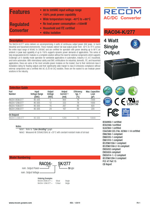
RAC AC/DC Conver er4 Watt Single OutputRAC04-K/277IEC60950-1 certified IEC62368-1certified UL62368-1 certifiedCSA/CAN C22.2 No. 62368-1-14 certified EN62368-1 compliant EN60335-1 compliant EN61010-1 compliant IEC/EN61558-1 compliant IEC/EN61558-2-16 compliant EN55032 compliant EN55024 compliantEN55014-1 /-2 compliant IEC/EN61204-3 compliant FCC 47 Part 15CB ReportSelection GuidePart Input Output Output Efficiency Max. CapacitiveNumber Voltage Range Voltage Current (1) typ. (2)Load [(VAC] [VDC] [mA] [%] [µF)RAC04-05SK/277 80-305 5 800 76 7200RAC04-12SK/277 80-305 12 333 78 1000RAC04-15SK/277 80-305 15 267 80 820RAC04-24SK/277 80-305 24 167 80 220On RequestRAC04-3.3SK/277 80-305 3.3 1200 73 10000Notes:Note1: Refer to “Line Derating“ graphNote2: Measured @ 230VAC/50Hz at +25°C with constant resistant mode at full loadDescriptionThe RAC04-K/277 series delivers an uncompromising 4 watts of continuous output power (6W peak) in harsh industrial and household environments. These modules deliver full load output power from -40°C to 75°C across the entire input range of 80VAC to 305VAC and are certified for operation with power derating up to 90°C air ambient. A peak load capability of up to 150% supports dynamic power demands of applications. This series of fully encapsulated AC/DC modules is a complete solution without the need for external components which supports Ecodesign Lot 6 standby mode operation for worldwide applications in automation, industry 4.0, IoT, household, and home automation. With international safety and EMC certifications for industrial, domestic, ITE, and household applications, these are some of the most versatile power modules on the market. Due to their reinforced class II installation rating for floating outputs and their significantly wide margin to class B emissions compliance without external components and a certified 4kV AC (5.25 kV DC) isolation, these are the easiest to use modular power solutions in the industry.nom. Output Power nom. Output VoltageRAC04-__ SK/277Model NumberingS ingleE224736Ordering Examples RAC04-05SK/277 = 5Vout Single RAC04-12SK/277 =12VoutSingleSpecifications (measured @ Ta= 25°C, nom. Vin, full load and after warm-up unless otherwise stated)Specifications (measured @ Ta= 25°C, nom. Vin, full load and after warm-up unless otherwise stated)REGULATIONSParameterCondition ValueOutput Accuracy ±1.0% typ.Line Regulation ±0.5% typ.Load Regulation 1.0% typ.Transient Response25% load step changerecovery time4.0% max.500µs10.5-0.5-1D e v i a t i o n [%]0102030405060708090100Output Load [%]10.50-0.5-1D e v i a t i o n [%]0102030405060708090100Output Load [%]RAC04-05SK/277RAC04-12SK/277Deviation vs. Load(80-305VAC)Specifications (measured @ Ta= 25°C, nom. Vin, full load and after warm-up unless otherwise stated)10.5-0.5-1D e v i a t i o n [%]0102030405060708090100Output Load [%]10.50-0.5-1D e v i a t i o n [%]0102030405060708090100Output Load [%]RAC04-15SK/277RAC04-24SK/277Specifications (measured @ Ta= 25°C, nom. Vin, full load and after warm-up unless otherwise stated)SAFETY AND CERTIFICATIONSCertificate Type Report / File Number StandardAudio/video, information and communication technology equipment - Safety requirements E224736UL62368-1:2014, 2nd Edition CAN/CSA C22.2 No. 62368-1-14, 2nd EditionInformation Technology Equipment, General Requirements for Safety (CB)E491408-A6-CB-1IEC60950-1:2005 + A2:2013, 2nd EditionInformation Technology Equipment, General Requirements for Safety EN60950-1:2006 + A2:2013 Audio/video, information and communication technology equipment - Safety requirements (CB)E491408-A6011-CB-1IEC62368-1:2014, 2nd Edition Audio/video, information and communication technology equipment - Safety requirements (LVD)EN62368-1:2014 + A11:2017 Household and similar electrical appliances - Safety - Part 1: General requirements (LVD)EN60335-1:2012 + A1:2018Safety of power transformers, power supplies, reactors and similar products for supply voltages up to 1100 V IEC61558-1:2005 2nd Edition + A1:2009EN61558-1:2005 + A1:2009Specifications (measured @ Ta= 25°C, nom. Vin, full load and after warm-up unless otherwise stated)Certificate Type Report / File Number StandardSafety of transformers, reactors, power supply units and similar products for supply voltages up to 1100 V - Part 2-16: Particular requirements and tests for switch mode power supply units and transformers for switch mode power supply units (LVD)IEC61558-2-16:2009 + A1:2013, 1st EditionEN61558-2-16:2009 + A1:2013Safety requirements for electrical equipment for measurement, control and laboratory use -Part 1: General requirements (LVD)EN61010-1:2010 RoHS2RoHs-2011/65/EU + AM-2015/863 EMC Compliance (Household)Report / File Number Standard / Criterion Electromagnetic compatibility - Requirements for household appliances, electric tools and similarapparatus - Part 1: Emission (8)EN55014-1:2006 + A2:2011 Electromagnetic compatibility - Requirements for household appliances, electric tools and similarapparatus - Part 2: ImmunityEN55014-2:2015 ESD Electrostatic discharge immunity test Air ±8kV; Contact ±4kV IEC61000-4-2:2008, Criteria B Fast Transient and Burst Immunity AC Power Port: ±1.0kV IEC61000-4-4:2012, Criteria B Surge Immunity AC Power Port: L-N ±1.0kV IEC61000-4-5:2014, Criteria B Immunity to conducted disturbances, induced by radio-frequency fields AC Power Port: 3V EN61000-4-6:2013, Criteria AVoltage Dips and Interruptions Voltage Dips: 100%60%EN61000-4-11:2004, Criteria CEN61000-4-11:2004, Criteria CEMC Compliance (Multimedia)Condition Standard / Criterion Low voltage power supplies, d.c. output - Part 3: Electromagnetic compatibility IEC/EN61204-3:2000, Class B Electromagnetic compatibility of multimedia equipment - Emission requirements (9)EN55032:2015, Class B Information technology equipment - Immunity characteristics - Limits and methods of measurement EN55024:2010 + A1:2015 ESD Electrostatic discharge immunity test Air ±2,4,8kV; Contact ±4kV IEC61000-4-2:2008, Criteria BRadiated, radio-frequency, electromagnetic field immunity test10V/m (80 - 1000MHz)IEC61000-4-3, Criteria A 3V/m (1800MHz, 2600Mhz,3500MHz, 5000MHz)IEC61000-4-3:2006 + A2:2010, Criteria AFast Transient and Burst Immunity AC Power Port: ±2.0kV IEC61000-4-4, Criteria B AC Power Port: ±1.0kV IEC61000-4-4:2012, Criteria ASurge Immunity AC Power Port: L-N ±1.0kV IEC61000-4-5:2014, Criteria A Immunity to conducted disturbances, induced by radio-frequency fields AC Power Port: 10V IEC61000-4-6, Criteria AVoltage Dips and Interruptions Voltage Dips:100% / 30%70%40%IEC61000-4-11:2004, Criteria AIEC61000-4-11:2004, Criteria BIEC61000-4-11:2004, Criteria C Interruptions: >95%IEC61000-4-11:2004, Criteria ALimits of Voltage Fluctuations & Flicker EN61000-3-3:2013 Limitations on the amount of electromagnetic interference allowed from digital and electronicdevicesFCC 47 Part 15 Subpart B:2017, Class B Notes:Note9: If output is connected to GND, please contact RECOM tech support for further informationDIMENSION and PHYSICAL CHARACTERISTICSParameter Type ValueMaterial case/baseplatepottingPCBplastic, (UL94 V-0)silicone, (UL94 V-0)FR4, (UL94 V-0)Dimension (LxWxH)36.7 x 27.2 x 17.4mm Weight30g typ.Specifications (measured @ Ta= 25°C, nom. Vin, full load and after warm-up unless otherwise stated)PACKAGING INFORMATIONParameter Type Value Packaging Dimension (LxWxH)tube506.4 x 29.8 x 25.5mm Packaging Quantity12pcs Storage Temperature Range-40°C to +85°C Storage Humidity non-condensing20% to 90% RH max.The product information and specifications may be subject to changes even without prior written notice.The product has been designed for various applications; its suitability lies in the responsibility of each customer. The products are not authorized for use in safety-critical applications without RECOM’s explicit written consent. A safety-critical application is an application where a failure may reasonably be expected to endanger or cause。
ldo 负电源转换

ldo 负电源转换LDO 负电源转换引言:LDO(低压差线性稳压器)是一种常见的电源管理器件,用于将高电压输入转换为稳定的低电压输出。
本文将重点介绍LDO 负电源转换的原理和应用。
一、LDO 负电源转换的原理LDO 负电源转换使用了负反馈控制的稳压技术,通过反馈电路将输出电压与参考电压进行比较,然后调节输出电压以使其稳定在设定值。
具体来说,LDO 负电源转换器由输入电源、稳压电路和输出负载组成。
1. 输入电源:输入电源通常为高电压直流电源,其电压范围可以从几伏到几十伏不等。
输入电源通过输入引脚输入到稳压电路中。
2. 稳压电路:稳压电路是LDO 负电源转换的核心部分,其通过反馈电路控制输出电压的稳定性。
稳压电路通常由一个参考电压源、一个误差放大器和一个功率放大器组成。
- 参考电压源:参考电压源是稳压电路的基准,其输出电压稳定且温度系数低,以提供给误差放大器作为比较基准。
- 误差放大器:误差放大器将输出电压与参考电压进行比较,并将比较结果放大后输出给功率放大器。
当输出电压偏离设定值时,误差放大器会产生一个控制信号。
- 功率放大器:功率放大器根据误差放大器的控制信号,调节输出电压以使其稳定在设定值。
功率放大器通常由一个或多个晶体管组成,通过调节负载电流来实现电压调节。
3. 输出负载:输出负载是LDO 负电源转换的目标,其可以是各种电子设备,如微处理器、存储器等。
输出负载通过输出引脚连接到稳压电路,从而获得稳定的电压供电。
二、LDO 负电源转换的应用LDO 负电源转换广泛应用于各种电子设备和系统中,以下是几个常见的应用场景:1. 电子产品:LDO 负电源转换器常用于手机、平板电脑、数码相机等电子产品中,用于提供稳定的电压给各个组件和模块。
2. 通信系统:通信系统中有许多对电压稳定性要求较高的模块,如射频模块、基带模块等。
LDO 负电源转换器可以提供稳定的电压给这些模块,以保证通信质量和性能。
3. 工业控制:在工业控制系统中,LDO 负电源转换器可用于给传感器、执行器和其他控制模块提供稳定的电源。
迅迪电子 XD308H 宽输入电压范围降压型 DC DC 转换器规格书说明书
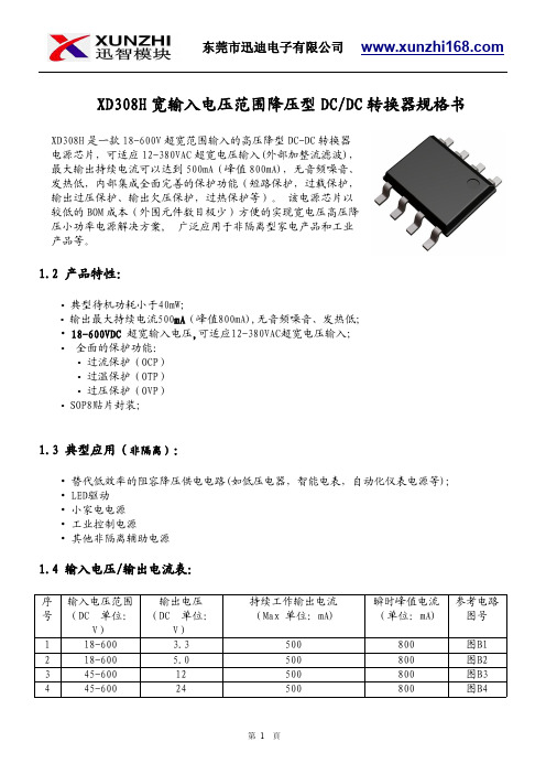
XD308H 宽输入电压范围降压型DC/DC 转换器规格书1.2产品特性:•典型待机功耗小于40mW;•输出最大持续电流500mA (峰值800mA),无音频噪音、发热低;•18-600VDC 超宽输入电压,可适应12-380VAC超宽电压输入;•全面的保护功能:•过流保护(OCP)•过温保护(OTP)•过压保护(OVP)•SOP8贴片封装;1.3典型应用(非隔离):•替代低效率的阻容降压供电电路(如低压电器,智能电表,自动化仪表电源等);•LED驱动•小家电电源•工业控制电源•其他非隔离辅助电源1.4输入电压/输出电流表:序号输入电压范围(DC 单位:V)输出电压(DC 单位:V)持续工作输出电流(Max 单位:mA)瞬时峰值电流(单位:mA)参考电路图号118-600 3.3500800图B1218-600 5.0500800图B2345-60012500800图B3445-60024500800图B4XD308H 是一款18-600V 超宽范围输入的高压降型DC-DC 转换器电源芯片,可适应12-380VAC 超宽电压输入(外部加整流滤波),最大输出持续电流可以达到500mA(峰值800mA),无音频噪音、发热低,内部集成全面完善的保护功能(短路保护,过载保护,输出过压保护、输出欠压保护,过热保护等)。
该电源芯片以较低的BOM 成本(外围元件数目极少)方便的实现宽电压高压降压小功率电源解决方案,广泛应用于非隔离型家电产品和工业产品等。
1.5封装参考:1.6引脚功能:编号名称描述备注1VCC/BP所有控制电路的电源。
外部旁路电容连接点2GND/S芯片参考地。
内部功率MOSFET的源极。
3FB反馈输入4CS电流检测5,6,7,8DRAIN内部功率MOSFET的漏极1.7功能框图:图11.8典型应用电路:1.9绝对最大额定值(备注1):1.10推荐的工作条件(备注2):参数数值单位工作环境温度-40to85°C1.11电气特性:=+25℃。
PowerVerter Plus 2400W 双接口工业级电源转换器产品说明书
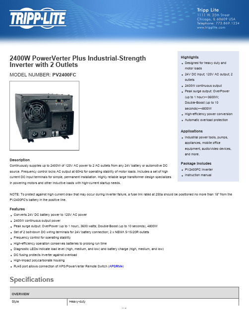
2400W PowerVerter Plus Industrial-Strength Inverter with 2 OutletsMODEL NUMBER: PV2400FC HighlightsDesigned for heavy duty andmotor loads24V DC input; 120V AC output; 2OUTPUTFrequency Compatibility60 HzOutput Receptacles(2) 5-15ROutput (Watts)2400Continuous Output Capacity (Watts)2400Peak Output Capacity (Watts)4800Output Nominal Voltage120VOutput Voltage Regulation Maintains PWM sine wave output voltage of 120 V AC (+/-5%)Output Frequency Regulation60 Hz (+/- 0.3 Hz)Overload Protection Circuit breakerINPUTRecommended Electrical Service Requires 24V DC input source capable of delivering 120A for the required duration (when used at full capacity). Forautomotive applications, professional hardwire installation with 250A battery system fusing is recommended Maximum Input Amps / Watts Full continuous load - 120A at 24V DC; No load - 2.2A at 24V DCInput Connection Type Set of 2 bolt-down DC wiring terminalsInput Cord Length Details User supplies cabling; 2/0 gauge or larger recommendedVoltage Compatibility (VDC)24BATTERYDC System Voltage (VDC)24LEDS ALARMS & SWITCHESSwitches3-position on/off/remote switch enables simple on/off power control plus "remote" setting that enables distant on/offcontrol of the inverter system when used in conjunction with optional APSRM4 accessoryFront Panel LEDs Set of 6 LEDs provides continuous status information on load percentage (6 levels reported) and battery chargelevel (7 levels reported). See manual for sequencesPHYSICALShipping Dimensions (hwd / in.)13.5 x 15 x 21.5Shipping Dimensions (hwd / cm)34.29 x 38.1 x 54.61Shipping Weight (lbs.)43Shipping Weight (kg)19.5Unit Dimensions (hwd / in.)7.25 x 8.5 x 16.25Unit Dimensions (hwd / cm)18.42 x 21.59 x 41.28Unit Weight (lbs.)39Unit Weight (kg)17.7Cooling Method FanMaterial of Construction PolycarbonateForm Factors Supported Mounting slots enable permanent placement of inverter on any horizontal surface (see manual for additionalmounting information)ENVIRONMENTALRelative Humidity0-95% non-condensingSPECIAL FEATURESRemote Control Capability YesWARRANTYProduct Warranty Period (Worldwide)1-year limited warranty© 2015 Tripp Lite. All rights reserved. All trademarks are the sole property of their respective owners. Tripp Lite has a policy of continuous improvement.Specifications are subject to change without notice. Photos may differ slightly from final products.。
Schneider Electric 产品数据手册 - 9070T1000D31 电源转换器说明书

Jan 4, 2020
1
Offer Sustainability
Sustainable offer status California proposition 65
- 1、下载文档前请自行甄别文档内容的完整性,平台不提供额外的编辑、内容补充、找答案等附加服务。
- 2、"仅部分预览"的文档,不可在线预览部分如存在完整性等问题,可反馈申请退款(可完整预览的文档不适用该条件!)。
- 3、如文档侵犯您的权益,请联系客服反馈,我们会尽快为您处理(人工客服工作时间:9:00-18:30)。
QCC小组、5S、质量成本等管理活动。通过将精益生产与六西格
玛的理念融入到产品实现过程,加速了流程优化与重组,使管理 进一步精细化、数据化、科学化,大幅度提升了产品和服务质量。 一个由优秀到卓越的航嘉,正向世界一流品质行列迈进。
ISO9001:2001
ISO14001:2004
QC080000
OHSAS18001
拓展电力电子应用领域。 为了确保研发产品保持技术上的领先优势,符合全球主要技术规范要求,航嘉不断加大自主研发投 入力度,建立了一流的研发和实验平台,先后设立EMC、MTBF、环境可靠性、安规、静音、风洞、
电网环境模拟、元器件应力分析等专业实验室,并获得TUV 、 UL 、CCC 等国内外认证机构的认可,
SSG504
Confidential
2012 HUNTKEY
航嘉电源转换器
智多星系列
Confidential
SSK501
Confidential
SSK501
Confidential
2012 HUNTKEY
SSK506
功能特点
Confidential
SSK506
Confidential
Confidential
航嘉技术 / HUNTKEY TECHNOLOGY
航嘉集结了来自各行业的精英,拥有一流的研发队伍(其中博士、硕士占20%,学士占60%)和 国际化的研发体系,是目前国内最大的电源研发和生产基地,十几年来的不断创新和经验积累使航嘉
的研发团队成为国内电源行业综合开发能力最强的团队,并与国内外高等院校、研究机构合作,共同
• •
2009年全球电源行业排名第五 “Huntkey” : PC电源行业最具 竞争力的品牌 PC电源国内市场份额:
•
40多项专利
Intel & AMD 战略合作伙伴
PC SMPS Inverter + converter
No.1
Adaptor/Charger
航嘉,连续十年排名国内PC电源行业首位,
世界电源企业排名第五位
航嘉荣誉
媒体颁发的各类荣誉
公司的产品
产品涵盖1W-250KW各类电源及电 源系统,涉及电源转换器、PC电源、 通信电源、电力电源、适配/充电器 、UPS、DC/DC等多类产品,
每一款电源均符合国际安全认证 标准,如CCC、UL、TUV、CE、CSA安 全认证和FCCB级认证。
成为他们的认证合作伙伴。
航嘉品质 / HUNTKEY QUALITY
质量方针: 正确地提供满足客户 所有需求的产品
航嘉始终以“正确地提供满足顾客所有需求的产品”作为质量宗
旨。1996年7月航嘉在国内同行中率先通过ISO9001认证,后续
航嘉不断完善公司的管理体系,先后通过了ISO14001、 OHSAS18001及QC080000体系认证。在此基础上坚持“过程防呆、 预防第一”的指导思想,全面导入和实施8D、TQM、TPM、SPC、
◆1995年 深圳驰源实业有限公司成立
关键字解读 首 位
航嘉,连续十年排名国内PC电源行业首位
五 强 30 亿
航嘉,世界电源企业排名第五位
航嘉,年产值30亿
唯 一 智 能
航嘉,USB电源转换器大陆地区唯一提供商
航嘉,智能电源转换器的倡导者
领航者
航嘉,电源产品发展趋势的领航者
航嘉企业机构是从事电力、电子系统开发、设计、制造及销售一体化的专业服务 机构 ,是国际电源制造商协会(PSMA)会员、中国电源行业协会(CPSS)副会长单位 、深圳市高新技术产业协会副会长单位、深圳市首届优秀民营企业。 航嘉创立于1995年,产品涵盖1W~250KW各类电源及电源系统,涉及PC电源、通 信电源、电力电源、适配/充电器、UPS、DC/DC、电脑机箱、五金、线材等多类产品 。 目前航嘉拥有员工近八千人,“航嘉”品牌已成为电源行业最具竞争力的品牌,其 中电脑电源国内市场占有率稳居第一,主要客户有海尔、联想、DELL、华为、 BESTBUY、中兴等国内外著名企业。
CCC,UL,TÜV,CE,CSA,FCC B …
二、航嘉电源转换器介绍
航嘉电源转换器产品系列
Confidential
航嘉电源转换器产品线
SSL303
SSH系列
中低端商超产品
SSH301 SSH401、402、404 SSH501、502、504
SSL系列
五金体系产品
SSL403 SSL503 SSL601 SSL801
◆2004年 航嘉(深圳)工业园投入使用; 荣获联想首届供应商大会高效供应金奖; 被评 为深圳 市诚信企业; 成为清华同方电脑优秀供应商; ◆2001年 成为“国际电源制造商协会(PSMA)”会员; ◆2000年 被评为深圳市高新技术企业;
◆1999年 航嘉电源LW-8180应用于获美国COMDEX/FALL 99 PC优秀设计奖的首台网络 电脑- 联想天禧电脑中; ◆1998年 通信电源产品DUM54-48/600S获国家重点新产品证书; ◆1997年 通信电源产品DUM54-48/600S系列通过电信部认证,用于国家通讯网络; ◆1996年 成为联想合格供应商;
航嘉(合肥)工业园
• 航嘉(合肥)工业园占地17万平方米.目前已投产。
优雅的办公环境
工业园一角
产品展示厅
办公楼大厅
齐全的配套设施
培训室
健身房
游泳池
“Hunt the Key” to Success
始建于1995
专业电源服务商 中国电源协会副会长单位 国际电源协会会员单位 员工: 8000多人 总资产: US$177M (RMB12亿)
Confidential
转换头产品
Confidential
THANK YOU !
Confidential
2011 HUNTKEY
另外,38万平方米的航嘉(河源)工业园也已经建成投产, 航嘉合肥工业 园也投入使用。
航嘉(深圳)工业园简介
• 航嘉(深圳)工业园占地6.5万平方米,建筑面积11 万平方米,是中国大陆目前最大的电脑电源制造基地。
航嘉(河源)工业园
• 航嘉(深圳)工业园占地26.8万平方米,总建筑面积38万平方米。主 要从事各类电源、五金模具、机箱机柜、精密组件等的开发、加工和 制造。
新国标系列
高端产品 电脑专用转换器
PSA603G
智多星系列
PSE系列 任我行系列
旅行插座
PSE001 PSE002
Confidential
航嘉电源转换器
巧管家系列
Confidential
SSH301
SSH401-2
SSH501
Confidential
SSH402 SSH502
SSH504
Confidential
电源转换器产品
高在阳
2013.09
Confidential
一、航嘉企业机构简介
成长的足迹
◆2009年 河源工业园第一期投入使用;航嘉成为华为优秀供应商; ◆2008年 被评为电子信息产品污染控制先进单位;开始为戴尔公司提供产品及服务; ◆2007年 荣获联想服务供应链大会服务金奖; 荣获方正科技集团特别支持供应商奖; 成 功收购良机湧旺电子科技(合肥)有限公司; ◆2006年 航嘉(河源)工业园奠基; 被深圳市龙岗区评为“双爱双评”活动先进单位; 荣 获联 想服务供应链合作伙伴最佳服务银奖; 被深圳市龙岗区评为自主创新龙头企 业; 荣获深圳市龙岗区区长质量奖; ◆2005年 成功收购深圳兴东立精密机械有限公司;
航嘉电源转换器
任我行系列
Confidentiential
PSE002
Confidential
2013航嘉电源转换器新品系列
组合孔位产品 独立开关产品 无线产品 转换头
Confidential
组合孔位产品
SSL603
SSL803
Confidential
独立开关产品
SSH404
Confidential
SSH601
Confidential
SSH801
Confidential
SSL303 SSL403
SSL503
Confidential
SSL601
SSL801
Confidential
SSL400
无开关产品
SSL600
SSF300
Confidential
研发优势
◆ 自有研发中心
◆ 先进的实验室设备
◆ 与认证机构长期的精诚合作 ◆ 与国内外著名研究机构和大学保持紧密的合作关系 提供: EMC测试、环境测试、振动测试、噪音分析实验室、模 拟电网工作环境实验室、 MTBF测试、 热能分析测试 成果: 40多项专利、Intel战略伙伴、AMD战略伙伴、国际电源制 造商协会成员、中国电源协会成员
SSF300 SSL400 SSL600 SSL410
巧管家系列 SSB系列
中端商超产品 基础级防雷产品
SSH601、801
SSB401 SSB601
SSG系列
中高端商超产品 专业级防雷产品
SSG404 SSG504
雷盾系列
SSB801
SSK系列
高端产品 音箱排插 电视排插
SSK501 SSK506
SSL410
无线无开关产品
Confidential
航嘉电源转换器
雷盾系列
Confidential
SSB401
Confidential
2013 HUNTKEY
SSB601
Confidential
SSB801
Confidential
