500SDP1S3M7QEA;中文规格书,Datasheet资料
人民电器 S、D、T、Q系列开关电源 产品说明书

S 、D 、T 、Q 系列开关电源
□ 采用进口元器件,可靠性高;内置滤波器,抗干扰性能好;直流纹波小,工作效率高;
设计软启动电路,交流浪涌电流限制;散热好,工作温度低,使用寿命长;输入电压范围宽,符合全球使用标准:绝缘性能好,抗电强度高;
具有短路、过载、过压保护功能;满负荷高温烧机,老化测试。
□ □ □ □ □ □ □ □ 100%
EMI 产品特点
S-15W 技术数据
S-25W
技术数据
051
052
S-35W 技术数据
S-50W 技术数据
S 、D 、T 、Q
系列开关电源
S-60W 技术数据
S-75W
技术数据
053
054
S-100W 技术数据
S-120W 技术数据
S 、D 、T 、Q
系列开关电源
S-145W 技术数据
S-150W
技术数据
055
056
S-200W 技术数据
S-201W 技术数据
S-240W 技术数据
S-250W 技术数据
S 、D 、T 、Q
系列开关电源
057
058
S-320W 技术数据
S-350W 技术数据。
英捷思500系列变频器
~2~
500 系列环境 .............................................................................................. 22 3.1.2 安装空间要求 ........................................................................................ 22 3.1.3 机械安装注意事项 ................................................................................. 23 3.2 电气安装 ........................................................................................................ 23 3.2.1 主回路端子说明..................................................................................... 23 3.2.2 变频器主回路接线方式 ........................................................................... 24 3.2.3 主回路配线注意事项 .............................................................................. 24 3.2.4 控制回路端子说明 ................................................................................. 26 3.2.5 端子接线图 ........................................................................................... 28 3.2.6 主控板跳线设置..................................................................................... 30 第四章 键盘操作说明 .................................................................................................. 31 4.1 操作与显示界面介绍 ....................................................................................... 31 4.1.1 功能指示灯说明..................................................................................... 31 4.2 键盘按键说明 ................................................................................................. 32 4.2.1 参数设置 .............................................................................................. 32 4.2.2 电机参数自学习..................................................................................... 33 4.2.3 密码设置 .............................................................................................. 35 第五章 功能参数表 ..................................................................................................... 35 5.1 基本功能参数简表........................................................................................... 35 5.2 监视参数简表 ................................................................................................. 68 第六章 参数说明 ........................................................................................................ 71 P0 组 基本功能组................................................................................................. 71
PWS500S安装指南说明书
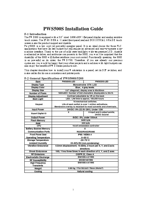
PWS500S Installation GuideF-1 IntroductionThe PWS500 is equipped with a 3.0" sized (160Hx80V) flat panel display and analog resistivetouch screen. The IP 65 (NEMA 4) rated front panel seal and INDUSTRIAL GRADE touch screen make the product rugged and durable.Pws-500S is a low cost yet powerful operator panel. It is an ideal choice for those PLC applications that have limited budget but still require an advanced and easy-to-operate man-machine interface. Thank to the use of solid state backlight, wide temperature LCD, durable mechanical switches, and anti-noise components in the 500S, you won’t be surprised that the durability of the 500S will further reinforce your cost control. Functionally speaking, the 500S is as powerful as its sister, the PWS-700. Therefore, if you are already our precious customers, you would be happy that your other projects and machines with tight budgets can also enjoy the benefit of PWS Series products now.This chapter describes how to install your Workstation in a panel, set its DIP switches, andmake cables for its communications and printer ports.F-2 General Specification of PWS500S/520SItem PWS500S-LED PWS520S-LED Display Type Monochrome STN LCDDisplay Color Blue ; 4 gray levelsDisplay Size 3.0" (diagonal); display area is 65x35mm Number of Pixels 160Hx80V; Number of 8x8 characters displayable is 20x10.Display Adjustment Contrast adjustable by VR on the backBack Light LED; Life time is approx. 100,000 hoursKeypad16 mechanical switches;Life of each switch is over 1 million activations; Membrane overlay is resistant to most solvents and chemicals.Input Power 24VDC±8% (22.5V-26V); Under 12WExport Digital IO X 8 Input and 8 output points;24VDC SourceOutput Power 5VDC±5%; under 100mAFlash Memory 640K byteRAM 32K byteCPU 16-bit embedded controllerBattery Backed Memory XCommunication Ports RS232/RS422/RS485Front Panel Seal IP65 / NEMA 4Operating Temperature 0~50°CStorage Temperature -20~70°CAmbient Humidity 20-90% RH (non-condensing)Vibration Endurance 0.5mm displacement, 10-55Hz, 2 hours per X, Y, and Z-axisdirectionsShock Endurance 10G, 11ms three times in each direction of X, Y, and Z axes RF Emissions CISPR 22, Class AElectrostatic Discharge EN61000-4-2/1995RF Susceptibility ENV50140/1993High FrequencyTransientsEN61000-4-4/1995Weight 0.65 Kg; 173x105.5x51.79mm (WxHxT)Cooling Natural coolingF-3. Dimensions of PWS500S/520SThis section illustrates the dimensions of the Workstations themselves as well as the cutout dimensions(160.8x93.3mm). The unit of dimensions is millimeter. You should allow 10 cm (4") of clearance behind the workstation for cable connectors and 5 cm (2") above and below for airflow.Rear viewCut out the mounting hole to match the dimensions shown below. Method of installation: Mount the PWS to the preserved hole from the front side. Attach the mounting brackets from behind, and fasten the screw of the brackets with a screwdriver.Insert the fixtures into mounting holes on the unit. Don't tighten the screws with too much force or it may cause a damage of the panel.F-3.1 Torque SpecificationsAfter placing the Workstation in the cutout, you should tighten each nut to 0.07 newton-meters (10 inch/pounds) of torque. If you don't have a torque wrench, then try to tighten the nuts to compress the gasket to about 50% of its original thickness.F-4. Power ConnectorThe three-position power connector accepts 24VDC only. The unit's power consumption is shown in the following:Item / Model 500S-LED 520S-LED Power Consumption 24VDC±10% 12W 24VDC±10% 12W Fuse Rating 0.5A 0.5ABe sure to use all three terminals when connecting power. To make a connection, strip about 0.64 cm (1/4") of insulation, turn the screw counter-clockwise until the gap is wide open, insert the wire all the way in, and turn the screw clockwise until it's tight.F-4.1 Electrical GroundingYou must make sure that your Workstation is properly connected to earth ground, to prevent it from radiating radio frequency noise. You should also ensure that the Workstation is on the same ground as any other equipment connected to its communications ports.If you connect a communications cable to your unit after static electricity has built up or when the Workstation and the other device are on different grounds, the resulting discharge could damage the electronics in ei t her device.F-5. Calibrating membrane function switchTo calibrate the membrane function switch,Set DIP switches SW3 and SW4 of the PWS500S to off. After power on, the PWS displays the following pattern. Figure 1F-5.1 Common Keys, Auxiliary Keys, and External KeysThere are three kinds of keys you can configure for the 500S with the ADP3:1) Common Keys - A common key is used to activate a designated function no matter what the current screen is. For example, you can press the key K1 to return to the screen 1 whenever you want if the key is configured as a common key that goes to screen 1. To configure common keys for your application, select Common Keys on the Application sub-menu of the ADP3 as shown in the Figure 2.Figure 22) Auxiliary Keys - A screen can have a number of auxiliary keys. The auxiliary keys of a screen are available for use only when that screen is the current screen. To configure auxiliary keys for a screen, select that screen first and then select Auxiliary Keys on the Screen sub-menu.3) External Keys – For a screen object requiring a real key to activate its function, you need to assign an external key switch as its external key when you configure that object. However, it is optional to assign an external key for a Numeric Entry, b ecause a Numeric Entry can also be selected by reserved arrow keys.Figure 3 Figure 4F-6 Setting of DIP SwitchesThere are ten DIP switches that you can access through the back cover. The purposes of these switches are stated in the following:SW1 System MenuON The Workstation displays System Menu after it gets a legal password or after power-on self-test if SW6 is off.OFF The Workstation doesnot display System Menu.SW2 Default User LevelON The default user level is one if the Workstation requires no password to start its operation.OFF The default user level is three if the Workstation requires no password to start its operation.SW4 SW3 Running ModeON ON Runs user application.ON OFF Off-line display screen did not link with PLCOFF ON Runs bench test program.OFF OFF Runs burn-in test program.SW5 COM2 PortON Enable RS485 circuitry of the COM2.OFF Enable RS422 circuitry of the COM2.SW6 PasswordON The Workstation asks the operator to enter a password after power-on self-test.OFF No password is required to start the Workstation.F-7 Self TestAfter power is applied, the Workstation runs a self-test that checks its hardware. After each test, the Workstation displays t h e result as shown in the following example. The version number of ROM BIOS refers to the EPROM chips, which will likely never change.If you have never configured your Workstation, the self-test may report a failure of the real time clock. If this happens, configure as described in section 10. If you have never downloaded an application to the Workstation, the self-test may report a problem in the flash chips. You can ignore these errors. If you have interrupted a download to the Workstation by switch ing off the power, disconnect the communication cable, or click cancel button in the ADP3 while a download is in progress, the self-test may report a problem in the Firmware Checksum or Application Checksum. You can ignore these errors and try to download again. If there are any items of the self-test the Workstation doesn't pass, the message "System error is detected! Press screen to continue.” appears. The Workstations continues its operation after you press screen.F-8. System MenuAfter the user level is determined by a password or by the default, the Workstation displays System Menu if the DIP switch No.1 is on; If DIP switch 7 is off, the Workstation starts running your application immediately.Warning: To avoid electric shock, be sure to switch off the power when connecting the communication/download cable to the PWS unit.F-10. Setting Operating ParametersYou can use Communication Parameter dialog box of ADP3 to set the parameters for the communications between your PWS500S and PLC. The parameters set in ADP3 is transmitted to the Workstation along with all other data when you download an application. The Workstation uses these parameters for PLC communications, if the DIP switch No.3 and No.4 are on.To get Communication Parameters dialog box, click Communications button in Workstation Setup dialog box. The Communication Parameter dialog box appears figure 5 with the following options:Figure 5F-11. Serial Communication Port2 (COM2 9pin female)COM 2 is a serial port that supports RS-232, RS-422, and RS-485 operation.The pin assignments of the port are listed in the following table:F-12. Password and User LevelThe 500S stores passwords in its Flash EPROM. A password has eight numeric characters.When you register a password, you must specify the user level associative with that password. The user level of a password determines the privilege of the user who enters that password tostart the operation of the 500S. When a user wants to use the function of the System Menu, change to another screen, or make change to a PLC location, the 500S checks the user's user level. There are three user levels: level 1, level 2, and level 3. Level 1 users have the highest privilege and Level 3 users have the lowest privilege.F-12.1 Registering PasswordsYou can register up to six passwords for your application in ADP3. To register passwords and their associated user level, click Password button on the Workstation Setup dialog box. The ADP3 displays the Password Table as shown in t he following figure. You can enter passwords as well as select the user level for them. The password data are part of the application data.Therefore, remember to compile your application and download it to the 500S when you make any changes to the password table. The default passwords are 00000000, 00000000, 00000000, 00000000, 00000000, and 00000000. The default user level is level 1.F-12.2 Setting the Lowest User LevelYou are able to set the current user level of the 500S to level 3 by pressing an Action button that is assigned the function of “Set Lowest User Level.”F-12.3 Displaying PasswordsTo display the passwords of your application on the 500S, you have to create an Action button on a screen and assign the function "Display Password Table" to that button. The 500S displays the password table as the example shown below, when a level 1 user presses and releases an Action button that is assigned the function of "Display Password Table."# Password Lvl1 22183600 12 12345678 23 12131415 34 00000000 35 00000000 36 00000000 3EscF-12.4 Reentering a PasswordWhen the 500S is running the user application, you can enter a password to change the current user level by pressing an Action button that is assigned the function of “Reenter Password.” To cancel the input of a new password, press [Esc].Figure 4 Entering a passwordNote that the default user level is 1 after the power-on self-test if the DIP switch SW2 is set to on; the default user level is 3 if the SW2 is set to off.When a screen object requiring a certain user level is activated and the current user level is higher than the specified user level with that screen object, the 500S automatically displays a box to let you enter a new password. This is a chance to change the current user level. The screen object proceeds to performs its function if a valid password with qualified user level is entered; otherwise, the 500S keeps on asking for a password or cancel the operationF-12.5 Entering PasswordAfter the self-test, if the DIP switch No.6 is on, the Workstation displays a keypad to prompt you to enter a password. If DIP switch No.6 is off, the Workstation doesn't ask you to enter a password and the default user level is 1 after the power-on self-test if the DIP switch SW2 is set to on; the default user level is 3 if the SW2 is set to off.If a password is required, the Workstation doesn't continue its operation until a legal password is entered.F-13. Adjusting Display ContrastYou can adjust the contrast of the STN LCD at any time the Workstation is running your application. The user can adjust the LCD contrast by screw the VR from rear cover.F-14. PWS520S-LED digital input and output specificationPWS520S-LED Digital IO with 20pin latch/ejector header pin assignmentInstallation screw nuts x4。
三星Sirius 200-480V 77A软启动器数据表说明书
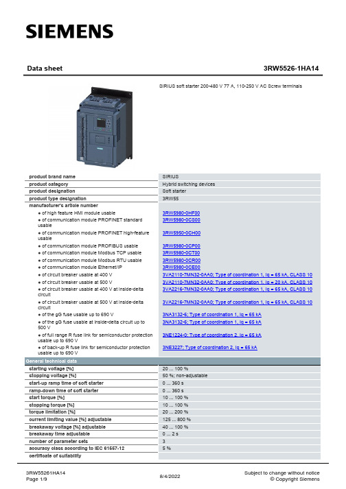
SIRIUS Hybrid switching devices Soft starter 3RW55
3RW5980-0HF00 3RW5980-0CSP00 3RW5980-0CT00 3RW5980-0CR00 3RW5980-0CE00 3VA2110-7MN32-0AA0; Type of coordination 1, Iq = 65 kA, CLASS 10 3VA2110-7MN32-0AA0; Type of coordination 1, Iq = 20 kA, CLASS 10 3VA2216-7MN32-0AA0; Type of coordination 1, Iq = 65 kA, CLASS 10
Data sheet
3RW5526-1HA14
SIRIUS soft starter 200-480 V 77 A, 110-250 V AC Screw terminals
product brand name product category product designation product type designation manufacturer's article number
3RW55261HA14 Page 1/9
8/4/2022
Subject to change without notice © Copyright Siemens
● CE marking ● UL approval ● CSA approval product component ● HMI-High Feature ● is supported HMI-High Feature product feature integrated bypass contact system number of controlled phases trip class current unbalance limiting value [%] ground-fault monitoring limiting value [%] buffering time in the event of power failure ● for main current circuit ● for control circuit idle time adjustable insulation voltage rated value degree of pollution impulse voltage rated value blocking voltage of the thyristor maximum service factor surge voltage resistance rated value maximum permissible voltage for safe isolation ● between main and auxiliary circuit shock resistance vibration resistance recovery time after overload trip adjustable utilization category according to IEC 60947-4-2 reference code according to IEC 81346-2 Substance Prohibitance (Date) product function ● ramp-up (soft starting) ● ramp-down (soft stop) ● breakaway pulse ● adjustable current limitation ● creep speed in both directions of rotation ● pump ramp down ● DC braking ● motor heating ● slave pointer function ● trace function ● intrinsic device protection ● motor overload protection
YMAHA P7000S 5000S 3500S 2500S 说明书
receptacles, and the point where they exit from the apparatus. 11 Only use attachments/accessories specified by the manufacturer. 12 Use only with the cart, stand, tripod, bracket, or table specified by the manufacturer, or sold with the apparatus. When a cart is used, use caution when moving the cart/ apparatus combination to avoid injury from tip-over. 13 Unplug this apparatus during lightning storms or when unused for long periods of time. 14 Refer all servicing to qualified service personnel. Servicing is required when the apparatus has been damaged in any way, such as powersupply cord or plug is damaged, liquid has been spilled or objects have fallen into the apparatus, the apparatus has been exposed to rain or moisture, does not operate normally, or has been dropped.
3590S-2-502L;3590S-2-102L;3590S-2-103L;3590S-2-203L;3590S-1-502L;中文规格书,Datasheet资料

Specifi cations are subject to change without notice.Customers should verify actual device performance in their specifi c applications.*RoHS Directive 2002/95/EC Jan. 27, 2003 including annex and RoHS Recast 2011/65/EU June 8, 2011.Stop Strength..............................................................................................................................................................................45 N-cm (64 oz.-in.) minimum Mechanical Angle ...........................................................................................................................................................................................3600 ° +10 °, -0 °Torque (Starting & Running) ................................................................................................................................0.35 N-cm (0.5 oz.-in.) maximum (unsealed) 1.1 N-cm (1.5 oz.-in.) maximum (sealed) Mounting ..............................................................................................................................................................................55-80 N-cm (5-7 lb.-in.) (plastic) 90-113 N-cm (8-10 in.-lb.) (metal)Shaft Runout......................................................................................................................................................................................0.13 mm (0.005 in.) teral Runout ...................................................................................................................................................................................0.20 mm (0.008 in.) T.I.R.Shaft End Play ...................................................................................................................................................................................0.25 mm (0.010 in.) T.I.R.Shaft Radial Play ...............................................................................................................................................................................0.13 mm (0.005 in.) T.I.R.Pilot Diameter Runout .......................................................................................................................................................................0.08 mm (0.003 in.) T.I.R.Backlash ............................................................................................................................................................................................................1.0 ° maximum Weight ........................................................................................................................................................................................................Approximately 19 G Terminals ................................................................................................................................................................................................Solder lugs or PC pins Soldering ConditionManual Soldering...........................................................96.5Sn/3.0Ag/0.5Cu solid wire or no-clean rosin cored wire; 370 °C (700 °F) max. for 3 seconds Wave Soldering ...................................................................................96.5Sn/3.0Ag/0.5Cu solder with no-clean fl ux; 260 °C (500 °F) max. for 5 seconds Wash processes .......................................................................................................................................................................................Not recommended Marking .....................................Manufacturer’s name and part number, resistance value and tolerance, linearity tolerance, wiring diagram, and date code.Ganging (Multiple Section Potentiometers) ......................................................................................................................................................1 cup maximum Hardware ............................................................................................................One lockwasher and one mounting nut is shipped with each potentiometer.NOTE: For Anti-rotation pin add 91 after confi guration dash number. Example: -2 becomes -291 to add AR pin.1At room ambient: +25 °C nominal and 50 % relative humidity nominal, except as noted. 2Consult manufacturer for complete specifi cation details for resistances below 1k ohms.BOLDFACE LISTINGS ARE IN STOCK AND READILY AVAILABLETHROUGH DISTRIBUTION. FOR OTHER OPTIONS CONSULT FACTORY.ROHS IDENTIFIER: L = COMPLIANTRecommended Part Numbers(Printed Circuit)(Solder Lug)(Solder Lug)Resistance (Ω)Resolution (%)3590P-2-102L 3590S-2-102L 3590S-1-102L 1,000.0293590P-2-202L 3590S-2-202L 3590S-1-202L 2,000.0233590P-2-502L 3590S-2-502L 3590S-1-502L 5,000.0253590P-2-103L 3590S-2-103L 3590S-1-103L 10,000.0203590P-2-203L 3590S-2-203L 3590S-1-203L 20,000.0193590P-2-503L 3590S-2-503L 3590S-1-503L 50,000.0133590P-2-104L3590S-2-104L3590S-1-104L100,000.009*Ro H S C O MP L I A N T/Panel Thickness Dimensions(For Bushing Mount Only)1.60 +.08/-.03(.063 +.003/-.001)DIA.ANTI-ROTATION PINAnti-rotation pin hole is shown at six o'clockposition for reference only. The actual location isdetermined by the customer's application. Referto the front view of the potentiometer to see thelocation of the optional A/R pin.Panel thickness and hole diameters arerecommended for best fit. However, customersmay adjust the dimensions to suit their specificapplication.Product DimensionsSpecifi cations are subject to change without notice.Customers should verify actual device performance in their specifi c applications.REV. 06/12 MOUNTING SURFACE-2, -4, -6, -8 Confi gurations-1, -3, -5, -7 Confi gurationsRecommended PCB LayoutHOLE DIAMETER5.08(.200)5.08(.200)6.99(.275)SchematicTOLERANCES: EXCEPT WHERE NOTED.508 .127DECIMALS: .XX ±(.02),.XXX ±(.005)FRACTIONS: ±1/64MMDIMENSIONS:(IN.)Shaft & Bushing Confi gurations(Bushing - DxL, Shaft - D):(-1) Plastic Bushing (3/8 ” x 5/16 ”)and Shaft (.2480 + .001, - .002)(-2) Metal Bushing (3/8 ” x 5/16 ”)and Shaft (.2497 + .0000, - .0009)(-3) Sealed, Plastic Bushing (3/8 ” x 5/16 ”)and Shaft (.2480 + .001, - .002)(-4) Sealed, Metal Bushing (3/8 ” x 5/16 ”)and Shaft (.2497 + .0000, - .0009)(-5) Metric, Plastic Bushing (9 mm x 7.94 mm)and Shaft (6 mm + 0, - .076 mm)(-6) Metric, Metal Bushing (9 mm x 7.94 mm)and Shaft (6 mm + 0, - .023 mm)(-7) Metric, Sealed, Plastic Bushing (9 mm x7.94 mm) and Shaft (6 mm + 0, - .076 mm)(-8) Metric, Sealed, Metal Bushing (9 mm x7.94 mm) and Shaft (6 mm + 0, - .023 mm)Terminal Styles“P” Terminal Style“S” Terminal Style/分销商库存信息:BOURNS3590S-2-502L3590S-2-102L3590S-2-103L 3590S-2-203L3590S-1-502L3590S-2-104L 3590S-1-203L3590S-2-501L3590S-2-202L 3590S-1-503L3590S-2-503L3590S-1-104L 3590S-291-102L3590S-291-203L3590S-291-502L 3590S-1-201L3590S-1-501L3590S-2-101L 3590S-2-201L3590P-1-102L3590P-1-103L 3590P-1-201L3590P-1-502L3590S-1-102L 3590S-1-103L3590S-2-252L3590P-291-501L 3590P-2-102L3590P-2-201L3590P-2-203L 3590P-2-502L3590S-1-202L3590S-6-102L 3590S-6-201L3590S-6-202L3590S-6-203L 3590S-6-501L3590P-1-104L3590S-6-502L 3590S-4-102L3590S-4-103L3590S-4-202L 3590S-4-203L3590S-4-502L3590S-8-102L 3590S-8-103L3590S-8-202L3590P-2-104L 3590P-4-103L3590P-4-202L3590S-6-503L 3590S-6-104L3590S-4-104L3590P-4-503L 3590P-4-104L3590S-2-5023590S-1-102 3590S-1-1033590S-1-1043590S-1-203 3590S-1-5023590S-1-5033590S-2-102 3590S-2-1033590S-2-1043590S-2-203 3590S-2-5033590S-1-2023590S-2-202 3590S-2-501。
Thermostat TC500A商品说明书
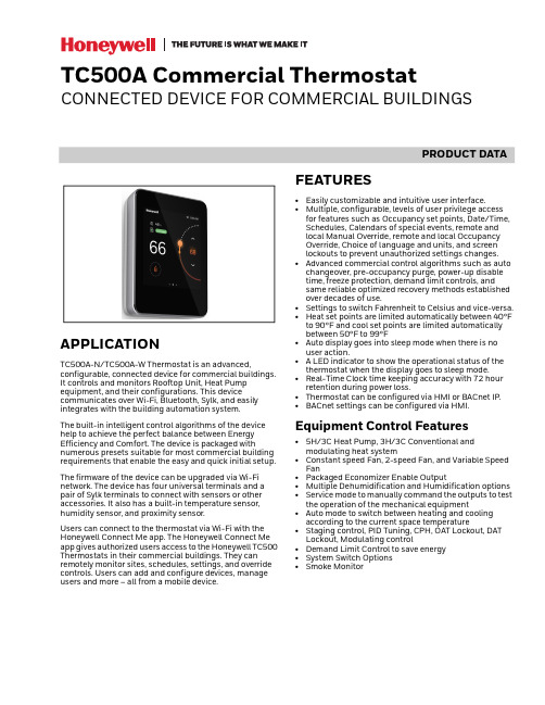
PRODUCT DATATC500A Commercial ThermostatCONNECTED DEVICE FOR COMMERCIAL BUILDINGSAPPLICATIONTC500A-N/TC500A-W Thermostat is an advanced,configurable, connected device for commercial buildings. It controls and monitors Rooftop Unit, Heat Pump equipment, and their configurations. This devicecommunicates over Wi-Fi, Bluetooth, Sylk, and easily integrates with the building automation system.The built-in intelligent control algorithms of the device help to achieve the perfect balance between Energy Efficiency and Comfort. The device is packaged withnumerous presets suitable for most commercial building requirements that enable the easy and quick initial setup.The firmware of the device can be upgraded via Wi-Fi network. The device has four universal terminals and a pair of Sylk terminals to connect with sensors or other accessories. It also has a built-in temperature sensor, humidity sensor, and proximity sensor.Users can connect to the thermostat via Wi-Fi with the Honeywell Connect Me app. The Honeywell Connect Me app gives authorized users access to the Honeywell TC500 Thermostats in their commercial buildings. They can remotely monitor sites, schedules, settings, and override controls. Users can add and configure devices, manage users and more – all from a mobile device.FEATURES•Easily customizable and intuitive user interface.•Multiple, configurable, levels of user privilege access for features such as Occupancy set points, Date/Time, Schedules, Calendars of special events, remote and local Manual Override, remote and local Occupancy Override, Choice of language and units, and screen lockouts to prevent unauthorized settings changes.•Advanced commercial control algorithms such as auto changeover, pre-occupancy purge, power-up disable time, freeze protection, demand limit controls, and same reliable optimized recovery methods established over decades of use.•Settings to switch Fahrenheit to Celsius and vice-versa.•Heat set points are limited automatically between 40°F to 90°F and cool set points are limited automatically between 50°F to 99°F•Auto display goes into sleep mode when there is no user action.• A LED indicator to show the operational status of the thermostat when the display goes to sleep mode.•Real-Time Clock time keeping accuracy with 72 hour retention during power loss.•Thermostat can be configured via HMI or BACnet IP.•BACnet settings can be configured via HMI.Equipment Control Features•5H/3C Heat Pump, 3H/3C Conventional and modulating heat system•Constant speed Fan, 2-speed Fan, and Variable Speed Fan•Packaged Economizer Enable Output•Multiple Dehumidification and Humidification options •Service mode to manually command the outputs to test the operation of the mechanical equipment•Auto mode to switch between heating and cooling according to the current space temperature•Staging control, PID Tuning, CPH, OAT Lockout, DAT Lockout, Modulating control•Demand Limit Control to save energy •System Switch Options •Smoke MonitorTC500A COMMERCIAL THERMOSTAT31-00398M-02 | Rev. 04-212TECHNICAL SPECIFICATIONSPower CharacteristicsDisplayIO CharacteristicsOperating EnvironmentTable 1. Power CharacteristicsPower SupplyRated voltage: 24VAC 50/60Hz,Working voltage range: 20-30VAC, UL listedclass-2 transformer or IEC 61558 listed transformer.Power Consumption (Display ON)Max. 8.5VA @ 24VAC (355mA @ 24VAC)Min. Load 4VA (all DOs OFF, No Sylk sensor)Max. Load96VA (all DOs ON)Table 2. DisplayDisplay Type 24 BPP TFT display with CTPResolutions 480x480 pixel Active Display Area 4” diagonally BacklightLCD (Dimmable)Table 3. IO CharacteristicsUIO x 2•Resistive Temperature Sensor Input—10K NTC type II, C7021 series —10K NTC type III,C7023 series —20K NTC, TR21 and C7041series.•Temperature Accuracy—±0.5°C (±1°F) at 10 – 32°C (50– 90°F)—±1.1°C (±2°F) at -1.1 – 50°C(30 – 122°F)•Voltage Input, SELV—0-10V, ±5% of full scale •Digital Input—Dry contact closure—Open circuit (≥ 100Kohms)—Closed circuit (≤100ohms)•Voltage Output—0-10V, ±3% of full scale @2KohmsUI x 2•Resistive Temperature Sensor Input—10K NTC type II, C7021 series —10K NTC type III,C7023 series —20K NTC, TR21 and C7041series•Temperature Accuracy—±0.5°C (±1°F) at 10 – 32°C (50– 90°F)—±1.1°C (±2°F) at -1.1 – 50°C(30 – 122°F)•Voltage Input, SELV—0-10V, ±5% of full scale •Digital Input—Dry contact closure—Open circuit (≥ 100Kohms)—Closed circuit (≤100ohms)DO (G,Y1,Y2,Y3,W1,W2,W3)•Relay Output— 1 Amps Max. at 24VAC DO (AUX)•Relay Dry Contact— 1 Amps Max. at 24VAC/DCTable 4. Operating EnvironmentAmbient Operating Temperature 32 to 122 °F (0 to +50°C)Ambient Operating Humidity 10 to 90% relative humidity (non-condensing)StorageTemperature -40 to 150 °F(-40 to 65.5°C)Protection ClassIP20Table 3. IO Characteristics (Continued)TC500A COMMERCIAL THERMOSTAT331-00398M-02 | Rev. 04-21CompliancesCommunication TechnologiesElectrical CharacteristicsSupported Sensors and FunctionsTable 5. CompliancesCertificates CE, FCC, ICES, UL/cUL, RoHs, REACH, California, Title 24, and Prop65.StandardsEN 60730-1, EN 60730-2-9, EN 301489-1, EN 301489-17, EN 300328, EN 301893, EN 62479, UL60730-1, UL60730-2-9, Title 47 part 15 subpart B, Title 47 part 15 subpart C, RSS 210, ICES-003Table 6. Communication TechnologiesBACnet IP Over Wi-FiWi-Fi802.11 b/g/nSupported security levels WPA,WPA3_WAP2_AES, WAP2_FBT_ENT, WPA2, WPA_ENT,WPA2_FBT, and WPA2_ENTBluetoothBLE 4.2 with 1 Mbps Classic Bluetooth with max. 3 Mbps Sylk TMHoneywell Sylk TMTable 7. Electrical CharacteristicsRated Impulse Voltage 500 VConstruction of Control Independently Mounted Control Operation Method Type 1 Action Pollution Degree 2Purpose of ControlOperating ControlTable 8. Supported Sensors and Functions Sensors Options Part Numbers Occupancy SensorDirect(Normally Open)Reverse (Normally Closed)Dry contactoccupancy sensorDirty Filter SensorDirect(Normally Open)Reverse (Normally Closed)DPS200, DPS400, DPS1000(Dry contact differentialpressure switch)Proof Of Air Flow SensorDirect(Normally Open)Reverse (Normally Closed)DPS200, DPS400, DPS1000(Dry contact airflow switch)Shutdown SensorDirect(Normally Open)Reverse (Normally Closed)Dry contactshutdown switchMixed Air Temperature Sensor NTC 20K, Type II NTC 10K, Type II SylkC7250C7021C7400S Outdoor Air Temperature Sensor NTC 20K, Type II NTC 10K, Type II Sylk C7250A C7021C7400S Return Air Temperature Sensor SylkC7400SDischarge Air Temperature Sensor NTC 20K, Type II NTC 10K, Type II SylkC7041C7021C7400SSpaceTemperature Sensors NTC 20K, Type II SylkTR21TR40/TR75 (max 4), TR120 (max 1)Fan Current Sensor Max Amps 0~<+Inf AmpsComing soonCO2 sensor (analog)0-10 VDC or Sylk Sylk C7232TR40-CO2, TR42-CO2Proof of waterflowDigital InputDry contactwaterflow switchTC500A COMMERCIAL THERMOSTAT31-00398M-02 | Rev. 04-214Terminal IdentificationFig. 1. TerminalsThermostat VariantsAccessoriesTable 9. Terminal IdentificationTerminalLabelConnection24VACR24VAC power from heating transformerC24VAC common (Neutral). For 2 transformer systems, use common wire from cooling transformerUIO11Universal input/output COM CommonUIO22Universal input/output COM Common UI11Universal input COM Common UI22Universal input COMCommonSylk (S-BUS)Sylk bus, master, power output Sylk bus, master, power outputRS485+BACnet Communications (coming soon)_BACnet Communications (coming soon)R-RCJumper between R and RC for single transformer system24VACRC 24VAC power from cooling transformer G FanY1Relay output, Compressor contactor (stage1)Y2Relay output, Compressor contactor (stage2)Y3Relay output, Compressorcontactor (stage3)/Configurable OutputW1Relay output, Heat (stage1)W2Relay output, Heat (stage2)W3Relay output, heat(stage3)/Configurable Output AuxRelay dry contact, Aux-1Relay dry contact, Aux-2Table 10. Thermostat Part NumbersTC500A-NThermostat with North American Wi-Fi conformanceTC500A-W (coming soon)Thermostat with outside of North American Wi-Fi conformanceTable 11. Accessories Part NumbersDecoplate-N TC500 deco plate for NA junction boxes Decoplate-WTC500 deco plate for Globe junction boxesTable 9. Terminal Identification TerminalLabel ConnectionTC500A COMMERCIAL THERMOSTAT531-00398M-02 | Rev. 04-21Terminal AssignmentsNOTE:*Marked sensors are supported in the future.Table 12. Terminal AssignmentsType Terminal LabelTerminal Assignments(Default & Optional Assignments)DEFAULTINPUTSOUTPUTSDigital OutputsDO1G Supply Fan High Speed FanDO2W1Heat Stage 1DO3W2Heat Stage 2DO4W3 / AuxHeat Stage 3Reversing Valve OB, Low Speed Fan,Occupancy, Simple Dehum, and Humidification.DO5Y1Cool Stage 1DO6Y2Cool Stage 2DO7Y3 / AuxCool Stage 3Economizer (Enable), Low Speed Fan,Occupancy, Simple Dehum, and Humidification.DO8(Dry Contact, 2 terminals)AuxEconomizer (Enable), Occupancy,Simple Dehum, Low Speed Fan, and Humidification.Universal InputsUI1(2 terminals)UI1NA Occupancy Sensor,Dirty Filter,Proof of Airflow,Shutdown Sensor,Mixed Air Sensor,Outdoor Air Sensor,Discharge Air Sensor,CO2 Sensor,Proof of Waterflow,Space Temp Sensor,*Filter Pressure sensor,*Compressor Current Sensor,*Fan Current Sensor,*Compressor Discharge, *Temperature sensor UI2(2 terminals)UI2NA Universal Inputs/ OutputsUIO1(2 terminals)UIO1NA Multi-Speed Fan (UIO1) Outdoor Air Damper UIO2(2 terminals)UIO2NAModulating Heat (UIO2) Outdoor Air DamperPowerRR 24v Power C C CommonRCRC 24v Power / Cooling Sylk Bus1S-BusSylk connection2TC500A COMMERCIAL THERMOSTAT31-00398M-02 | Rev. 04-216DIMENSIONS3 - 1/4” (82.75mm)TC500A COMMERCIAL THERMOSTAT731-00398M-02 | Rev. 04-21GENERAL SAFETY INFORMATION•When performing any work (installation, mounting, start-up), all manufacturer instructions and in particular the mounting Instructions guide (31-00399M) and the user guide (31-00400M) are to be observed.•TC500A-N/TC500A-W Thermostat may be installed and mounted only by authorized and trained personnel.•Rules regarding electrostatic discharge should be followed.•If TC500A-N/TC500A-W Thermostat is modified in any way, except by the manufacturer, all warranties concerning operation and safety are invalidated.•Make sure that the local standards and regulations are observed at all times.•Use only accessory equipment which comes from or has been approved by Honeywell.•It is recommended that devices be kept at roomtemperature for at least 24 hours before applying power. This is to allow any condensation resulting from low shipping/storage temperatures to evaporate.•Investigated according to United States Standard UL-60730-1, and UL60730-2-9.•Investigated according to Canadian National Standard(s) C22.2, No. 205-M1983 (CNL-listed).•Do not open TC500A-N/TC500A-W Thermostat, as it contains no user-serviceable parts inside!•CE declarations according to LVD Directive 2014/35/EU and EMC Directive 2014/30/EU.•Product standards are EN 60730-1 and EN 60730-2-9.•TC500A-N/TC500A-W Thermostat is Class B digital apparatus and complies with Canadian ICES-003.•This device complies with part 15 of the FCC Rules. Operation is subject to the following two conditions: (1) This device may not cause harmful interference, and (2) this device must accept any interference received, including interference that may cause undesired operation.•Caution: Changes or modifications to this unit not expressly approved by the party responsible forcompliance could void the user's authority to operate the equipment.•This device contains licence-exempttransmitter(s)/receiver(s) that comply with Innovation, Science and Economic Development Canada’s licence-exempt RSS(s). Operation is subject to the following two conditions:1.This device may not cause interference.2.This device must accept any interference, includinginterference that may cause undesired operation of the device.•L’émetteur/récepteur exempt de licence contenu dans le présent appareil est conforme aux CNR d’Innovation, Sciences et Développement économique Canada applicables aux appareils radio exempts de licence. L’exploitation est autorisée aux deux conditions suivantes:1.L’appareil ne doit pas produire de brouillage;2.L’appareil doit accepter tout brouillage radioélec -trique subi, même si le brouillage est susceptible d’en compromettre le fonctionnement.•This equipment has been tested and found to comply with the limits for a Class B digital device, pursuant to part 15 of the FCC Rules. These limits are designed to provide reasonable protection against harmfulinterference in a residential installation. This equipment generates uses and can radiate radio frequency energy and, if not installed and used in accordance with the instructions, may cause harmful interference to radio communications. However, there is no guarantee that interference will not occur in a particular installation. If this equipment does cause harmful interference to radio or television reception, which can be determined by turning the equipment off and on, the user isencouraged to try to correct the interference by one or more of the following measures:—Reorient or relocate the receiving antenna.—Increase the separation between the equipmentand receiver.—Connect the equipment into an outlet on a circuitdifferent from that to which the receiver is con -nected.—Consult the dealer or an experienced radio/TV tech -nician for help.•To satisfy FCC&IC RF exposure requirements, a separation distance of 20 cm or more should be maintained between the antenna of this device andpersons during device operation. To ensure compliance, operations at closer than this distance is not recommended.•Les antennes installées doivent être situées de facon à ce que la population ne puisse y être exposée à une distance de moin de 20 cm. Installer les antennes de facon à ce que le personnel ne puisse approcher à 20 cm ou moins de la position centrale de l’ antenne. Region Selection (for Wi-Fi 2.4G device)•Limited by local law regulations, version for North America does not have region selection option.Safety Information as per EN60730-1TC500A-N/TC500A-W Thermostat is intended for residential, commercial environments.TC500A-N/TC500A-W Thermostat is an independently mounted electronic control system with fixed wiring.TC500A-N/TC500A-W Thermostat is used for the purpose of building HVAC control and is suitable for use only in non-safety controls for installation on or in appliances.NoteAll images used in this document are for illustrative purposes only and may not match the actual product.TC500A COMMERCIAL THERMOSTAT® U.S. Registered Trademark© 2021 Honeywell International Inc.31-00398M-02 | Rev. 04-21Honeywell Building TechnologiesHoneywell715 Peachtree Street NE Atlanta, GA 。
SI5504BDC-T1-E3;中文规格书,Datasheet资料
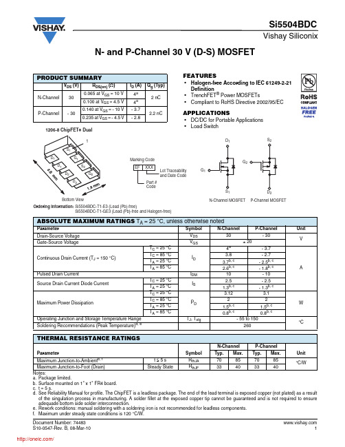
N- and P-Channel 30 V (D-S) MOSFETPRODUCT SUMMARYV DS (V)R DS(on) (Ω)I D (A)Q g (Typ)N-Channel 300.065 at V GS = 10 V 4a 2 nC 0.100 at V GS = 4.5 V 4a P-Channel- 300.140 at V GS = - 10 V - 3.7 2.2 nC0.235 at V GS = - 4.5 V- 2.8Notes:a.Package limited.b.Surface mounted on 1" x 1" FR4 board.c.t = 5 s.d.See Reliability Manual for profile. The ChipFET is a leadless package. The end of the lead terminal is exposed copper (not plated) as a result of the singulation process in manufacturing. A solder fillet at the exposed copper tip cannot be guaranteed and is not required to ensure adequade bottom side solder interconnection.e.Rework conditions: manual soldering with a soldering iron is not recommended for leadless components.f.Maximum under steady state conditions is 120 °C/W.ABSOLUTE MAXIMUM RATINGS T A = 25°C, unless otherwise notedParameter Symbol N-Channel P-Channel UnitDrain-Source VoltageV DS 30- 30VGate-Source VoltageV GS ± 20Continuous Drain Current (T J = 150 °C)T C = 25 °C I D 4a - 3.7A T C = 85 °C 3.8- 2.7T A = 25 °C 3.7b, c - 2.5b, c T A = 85 °C 2.6b, c- 1.8b, c Pulsed Drain Current I DM 10- 10Source Drain Current Diode CurrentT C = 25 °C I S 2.5- 2.5T A = 25 °C 1.3b, c - 1.3b, c Maximum Power Dissipation T C = 25 °C P D 3.12 3.1W T C = 85 °C 22T A = 25 °C 1.5b, c 1.5b, c T A = 85 °C 0.8b, c0.8b, c Operating Junction and Storage Temperature Range T J , T stg - 55 to 150°C Soldering Recommendations (Peak Temperature)d, e260THERMAL RESISTANCE RATINGSParameter Symbol N-ChannelP-ChannelUnitTyp.Max.Typ.Max.Maximum Junction-to-Ambient b, f t ≤ 5 s R thJA 70857085°C/WMaximum Junction-to-Foot (Drain)Steady State R thJF 33403340FEATURES•Halogen-free According to IEC 61249-2-21Definition•TrenchFET ® Power MOSFETs•Compliant to RoHS Directive 2002/95/ECAPPLICATIONS•DC/DC for Portable ApplicationsNotes:a. Guaranteed by design, not subject to production testing.b. Pulse test; pulse width ≤ 300 µs, duty cycle ≤ 2 %.SPECIFICATIONS T J = 25°C, unless otherwise notedParameter Symbol Test Conditions Min.Typ.Max.UnitStaticDrain-Source Breakdown Voltage V DS V GS = 0 V , I D = 250 µA N-Ch 30V V GS = 0 V, I D = - 250 µAP-Ch - 30V DS Temperature Coefficient ΔV DS /T J I D = 250 µA N-Ch 27mV/°CI D = - 250 µA P-Ch - 30V GS(th) Temperature Coefficient ΔV GS(th)/T J I D = 250 µA N-Ch - 5I D = - 250 µA P-Ch 3.5Gate Threshold Voltage V GS(th) V DS = V GS , I D = 250 µA N-Ch 1.53VV DS = V GS , I D = - 250 µA P-Ch - 1.5- 3Gate-Body LeakageI GSSV DS = 0 V , V GS = ± 20 V N-Ch 100nAP-Ch - 100Zero Gate Voltage Drain CurrentI DSSV DS = 30 V, V GS = 0 VN-Ch 1µAV DS = - 30 V , V GS = 0 V P-Ch - 1V DS = 30 V , V GS = 0 V, T J = 85 °C N-Ch 5V DS = - 30 V, V GS = 0 V , T J = 85 °CP-Ch - 5On-State Drain CurrentbI D(on)V DS ≥ 5 V , V GS = 10 V N-Ch 10A V DS ≤ - 5 V , V GS = - 10 V P-Ch - 10Drain-Source On-State Resistance b R DS(on)V GS = 10 V , I D = 3.1 A N-Ch 0.0530.065ΩV GS = - 10 V , I D = - 2.1 A P-Ch 0.1120.140V GS = 4.5 V, I D = 1 A N-Ch 0.0810.100V GS = - 4.5 V , I D = - 0.43 A P-Ch 0.1880.235Forward T ransconductance b g fsV DS = 15 V , I D = 3.1 A N-Ch 5S V DS = - 15 V , I D = - 2.1 AP-Ch 3.5Dynamic aInput Capacitance C iss N-ChannelV DS = 15 V, V GS = 0 V , f = 1 MHz P-ChannelV DS = - 15 V , V GS = 0 V , f = 1 MHz N-Ch220pFP-Ch 170Output CapacitanceC oss N-Ch 50P-Ch 50Reverse Transfer CapacitanceC rssN-Ch 25P-Ch 31Total Gate Charge Q gV DS = 15 V, V GS = 10 V, I D = 3.6 AN-Ch 4.57nC V DS = - 15 V , V GS = - 10 V , I D = - 2.5 A P-Ch 4.57N-ChannelV DS = 15 V , V GS = 4.5 V , I D = 3.6 AP-ChannelV DS = - 15 V , V GS = - 4.5 V , I D = - 2.5 AN-Ch 23P-Ch 2.2 3.5Gate-Source Charge Q gs N-Ch 0.7P-Ch 0.7Gate-Drain Charge Q gd N-Ch 0.7P-Ch 1Gate ResistanceR gf = 1 MHzN-Ch 3ΩP-Ch13Notes:a. Guaranteed by design, not subject to production testing.b. Pulse test; pulse width ≤ 300 µs, duty cycle ≤ 2 %.Stresses beyond those listed under “Absolute Maximum Ratings” may cause permanent damage to the device. These are stress ratings only, and functional operation of the device at these or any other conditions beyond those indicated in the operational sections of the specifications is not implied. Exposure to absolute maximum rating conditions for extended periods may affect device reliability.SPECIFICATIONS T J = 25°C, unless otherwise notedParameter Symbol Test Conditions Min.Typ.Max.UnitDynamic aT urn-On Delay Time t d(on) N-ChannelV DD = 15 V, R L = 5.8 Ω I D ≅ 2.6 A, V GEN = 4.5 V , R g = 1 ΩP-ChannelV DD = - 15 V , R L = 7.5 Ω I D ≅ - 2 A, V GEN = - 4.5 V , R g = 1 ΩN-Ch1525nsP-Ch 3045Rise Timet r N-Ch 80120P-Ch 6090T urn-Off Delay Time t d(off) N-Ch 1220P-Ch 1015Fall Timet f N-Ch 2540P-Ch 1015T urn-On Delay Time t d(on) N-ChannelV DD = 15 V, R L = 5.8 Ω I D ≅ 2.6 A, V GEN = 10 V , R g = 1 ΩP-ChannelV DD = - 15 V , R L = 7.5 Ω I D ≅ - 2 A, V GEN = - 10 V , R g = 1 ΩN-Ch48P-Ch 48Rise Timet r N-Ch 1220P-Ch 1015T urn-Off Delay Time t d(off) N-Ch 1015P-Ch 1015Fall Timet fN-Ch 510P-Ch510Drain-Source Body Diode Characteristics Continuous Source-Drain Diode Current I S T C = 25 °CN-Ch 2.5AP-Ch - 2.5Pulse Diode Forward Current a I SM N-Ch 10P-Ch - 10Body Diode VoltageV SD I S = 2.6 A, V GS = 0 V N-Ch 0.8 1.2V I S = - 2 A, V GS = 0 VP-Ch - 0.8- 1.2Body Diode Reverse Recovery Time t rr N-ChannelI F = 2.6 A, dI/dt = 100 A/µs, T J = 25 °C P-ChannelI F = - 2 A, dI/dt = - 100 A/µs, T J = 25 °CN-Ch 3050ns P-Ch 2040Body Diode Reverse Recovery Charge Q rr N-Ch 2040nC P-Ch 1020Reverse Recovery Fall Time t a N-Ch 23nsP-Ch 13Reverse Recovery Rise Timet bN-Ch 7P-Ch7N-CHANNEL TYPICAL CHARACTERISTICS 25°C, unless otherwise notedOutput CharacteristicsOn-Resistance vs. Drain CurrentTransfer CharacteristicsCapacitanceN-CHANNEL TYPICAL CHARACTERISTICS 25°C, unless otherwise notedSource-Drain Diode Forward VoltageThreshold VoltageSingle Pulse PowerSafe Operating Area, Junction-to-AmbientN-CHANNEL TYPICAL CHARACTERISTICS 25°C, unless otherwise noted* The power dissipation P D is based on T J(max) = 150 °C, using junction-to-case thermal resistance, and is more useful in settling the upper dissipation limit for cases where additional heatsinking is used. It is used to determine the current rating, when this rating falls below the package limit.Current Derating*Power DeratingN-CHANNEL TYPICAL CHARACTERISTICS 25°C, unless otherwise notedTransfer CharacteristicsCapacitanceOn-Resistance vs. Junction TemperatureP-CHANNEL TYPICAL CHARACTERISTICS 25°C, unless otherwise notedSource-Drain Diode Forward VoltageSingle Pulse PowerP-CHANNEL TYPICAL CHARACTERISTICS 25°C, unless otherwise noted* The power dissipation P D is based on T J(max) = 150 °C, using junction-to-case thermal resistance, and is more useful in settling the upper dissipation limit for cases where additional heatsinking is used. It is used to determine the current rating, when this rating falls below the package limit.Current Derating*分销商库存信息: VISHAYSI5504BDC-T1-E3。
S7500E+SA系列单板datasheet

H3C S7500E产品SA系列单板 datasheet 杭州华三通信技术有限公司目录1 概述 (1)2 主要特点 (1)2.1 SA单板QinQ/VLAN Mapping能力 (1)3 业务特性 (1)3.1 强大的L2特性 (1)3.2 支持IPv4&IPv6双协议栈 (2)3.2.1 IPv4特性 (2)3.2.2 IPv6特性 (2)3.2.3 路由协议 (3)3.3 丰富的组播特性 (3)3.4 全面的QOS&ACL能力 (3)3.5 良好的用户管理界面 (4)3.5.1 本地管理 (4)3.5.2 网络管理 (4)4 单板规格 (4)4.1 单板类型列表 (4)4.2 LSQ1FP48SA0单板 (5)4.2.1 单板实物图 (5)4.2.2 单板属性 (5)4.2.3 指示灯 (6)4.3 LSQ1FV48SA0单板 (6)4.3.1 单板实物图 (6)4.3.2 单板属性 (6)4.3.3 指示灯 (7)4.4 LSQ1GV48SA0单板 (8)4.4.1 单板实物图 (8)4.4.2 单板属性 (8)4.4.3 指示灯 (9)5 可插拔模块汇总 (9)5.1 百兆SFP模块 (9)6 运行环境 (10)7 安全标准 (10)8 EMC标准 (10)1 概述H3C S7500E系列以太网交换机产品是杭州华三通信技术有限公司(以下简称H3C公司)面向融合业务网络推出的新一代高端多业务路由交换机,该产品基于H3C自主知识产权的Comware V5操作系统,融合了MPLS、IPv6、网络安全、无线、无源光网络等多种业务,提供不间断转发、优雅重启(Graceful Restart)、环网保护等多种高可靠技术,在提高用户生产效率的同时,保证了网络最大正常运行时间,从而降低了客户的总拥有成本(TCO)。
H3C S7500E符合“限制电子设备有害物质标准(RoHS)”,是绿色环保的路由交换机。
普传科技PI500A-S系列光伏水泵变频器使用说明书

PI500A-S系列光伏水泵变频器使用说明书1.序言感谢选用普传科技的PI500A-S 系列基本型光伏水泵变频器。
本操作说明的示图,是为了方便说明,可能与产品会略有不同,由于产品升级,也可能略有不同,请以实物为准。
请注意将本使用手册交到最终用户手中,并妥善保存,以便日后检修、维护时使用。
如有疑问,请及时与本公司或本公司代理商取得联系,我们将竭诚为您服务。
2.铭牌说明型号说明:普传变频器2R2:2.2kW 004:4kW系列代号产品功能代号 G:标准负载3.外形尺寸支持导轨安装0.75~4kW G3外形尺寸5.5-11kW G3外形尺寸15~22kW G3外形尺寸3.1.单相AC 220V /DC150-450V外形尺寸图及安装尺寸3.2.三相AC 220V/DC150-450V外形尺寸图及安装尺寸3.3.三相AC 380V/DC250V-800V外形尺寸图及安装尺寸3.4.三相AC 480V/DC400V-900V外形尺寸图及安装尺寸※注:推荐太阳能电池组件功率为变频器功率的1.2倍以上。
4.操作键盘介绍图4-1:操作面板显示Hz 频率单位A 电流单位V 电压单位RPM 转速单位% 百分数参数设定退出键移位键递增键递减键运行键停止确认键快捷多功能键键盘电位器6.配线图主回路配线注意事项(1)配线线路规格,请按照电工法规规定实行配线;(2)请勿将交流电接至变频器输出端(U、V、W),否则会引起变频器损坏;(3)电源配线,请尽量使用隔离线与线管,并将隔离线或线管两端接地;(4)变频器接地线不可与电焊机、大功率电机或大电流负载共同接地,请单独接地;(5)接地端子请正确接地,接地阻抗小于10Ω;控制回路配线注意事项(1)请把控制信号线与主回路线、及其他动力线,电源线分开走线。
(2)为防止干扰而引起误动作,请使用绞合屏蔽线或双股屏蔽线,规格为0.5~2mm²(3)请确定各使用端子允许条件,如:电源、最大允许电流等;(4)各端子接线要求,正确选用配件,如:电压表、输入电源等;(5)完成配线后请正确检查,确认无误后方可上电。
SN75107BD 数据手册说明书
SN75107AJ SN75107BJ SN75108AJ SN75108BD SN75108BJ SN75108BN SN75109AJ
SN75109J
SN75109N
SN7510FA SN7510FA SN7510FA SN7510FA SN7510L SN7510L SN7510L SN7510P SN7510P SN7510P SN7511FA
N/A
IC Datasheets -
/SN7510L-datasheet.html
Shortform
Texas Instruments
Differential Video Amplifier
/SN7510L-datasheet.html
Advanced Micro Devices
Differential DriverTransmitter - ConstantCurrent Output
/SN75109N-datasheet.html
Texas Instruments
General Purpose Video Amplifier
Shortform
Texas Instruments
Differential Video Amplifier
/SN7510P-datasheet.html
Texas Instruments
General Purpose Video Amplifier
Differential Video Amplifier
/SN7510FA-datasheet.html
Texas Instruments
General Purpose Video Amplifier
H11L1S(TA),H11L1S(TA),H11L1S(TA),H11L1M,H11L1,H11L2M,H11L2,H11L3M, 规格书,Datasheet 资料
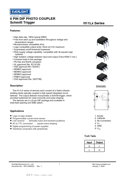
Schmitt TriggerH11Lx SeriesFeatures:• High data rate, 1MHz typical (NRZ)• Free from latch up and oscilliation throughout voltage and temperature ranges.• Microprocessor compatible drive• Logic compatible output sinks 16mA at 0.4V maximum • Guaranteed on/off threshold hysteresis• Wide supply voltage capability, compatible with all popular logic systems• High isolation voltage between input and output (Viso=5000 V rms ) • Compact dual-in-line package • Pb free and RoHS compliant. • UL approved (No. E214129) • VDE approval (No.132249 ) • SEMKO approved • NEMKO approved • DEMKO approved• FIMKO approved• CSA approved (No. 2007798)SchematicDescriptionThe H11LX series of devices each consist of a GaAs infrared emitting diode optically coupled a high speed integrated circuit detector. The output detector incorporates a Schmitt trigger, which provides hysteresis for noise immunity and pulse shaping. The devices are in a 6-pin DIP package and available in wide-lead spacing and SMD option.Applications1. Anode2. Cathode3. No Connection4. V O5. GND6. V CCz Logic to logic isolatorz Programmable current level sensorz Line receiver - eliminate noise and transient problems z AC to TTL conversion - square wave shaping z Digital programming of power supplies z Interfaces computers with peripheralsTruth TableInput Output H L L HSchmitt Trigger H11Lx SeriesAbsolute Maximum Ratings (T a =25°C)Parameter Symbol Rating Unit Forward currentI F 60 mA Reverse voltage V R 6 V InputPower dissipation P D 120 mW V 45 Allowed RangeV o 0 to 16 V V 65 Allowed Range V CC3 to 16VOutput Current I 0 50 mA Outputpower dissipationP D 150 mW Total power dissipation P tot 250 mW Isolation voltage *1 V iso 5000 V rms Operating temperature T opr -55~+100 °C Storage temperature T stg -55~+150 °C Soldering temperature *2 T sol260 °CNotes*1 AC for 1 minute, R.H.= 40 ~ 60% R.H. In this test, pins 1, 2 & 3 are shorted together, and pins 4, 5 & 6 are shorted together. *2 For 10 seconds.Schmitt Trigger H11Lx SeriesElectrical Characteristics (T a =25°C unless specified otherwise)InputParameter Symbol Min. Typ.* Max. Unit ConditionForward voltageV F - 1.15 1.5 V I F = 10mA Reverse Leakage current I R - - 10 µA V R = 5VCapacitanceC J- - 100 pF V=0, f=1MHzOutputParameter Symbol Min. Typ.* Max. Unit ConditionOperation Voltage Range V CC 3 - 15 V Supply Current I CC(off) - 1.6 5 mA I F =0mA, Vcc=5V Output Current, High I OH- - 100 µA I F =0mA, Vcc=Vo=15VIsolation ResistanceR ISO 1011- -Ω V I-O =500VDCTransfer CharacteristicsParameter Symbol Min. Typ.* Max. Unit ConditionSupply Current I CC(on) - 1.6 5 mA I F =10mA, Vcc=5V Output Voltage .lowV OL- - 0.4 VVcc=5V, I F =I Fon (max.), R L =270ΩH11L1 - -1.6 H11L2 - - 10Turn on ThresholdCurrent 1H11L3I Fon- - 5 mA Vcc=5V, R L =270Ω Turn off Threshold Current I Foff - 1 - mA Vcc=5V, R L =270Ω Hysteresis Ratio I Fon /I Foff 0.5 - 0.9 Vcc=5V, R L =270ΩTurn on Time t on - - 4 μS Fall Time t r - 0.1 - μS Turn off Time t off - - 4 μS Rise Time t r - 0.1 - μS Vcc=5V, I F =I Fon , R L =270ΩData Rate- 1 - MHz* Typical values at T a = 25°C 1. Max. I F(ON) is the maximum current required to trigger the output. For examples, a 1.6mA maximum trigger current would require the LED to be driven at a current greater than 1.6mA to guarantee the device will turn on. A 10% guard band is recommended to account for degradation of the LED over its lifetime. The maximum allowable LED drive current is 60mA.Schmitt TriggerH11Lx SeriesTypical Performance CurvesSchmitt TriggerH11Lx SeriesOrder InformationPart NumberH11LXY(Z)-VNoteX = Part No. for 1, 2 or 3Y = Lead form option (S, S1, M or none)Z = Tape and reel option (TA, TB or none).V = VDE (optional)quantity Option Description PackingNone Standard DIP-6 65 units per tubeM Wide lead bend (0.4 inch spacing) 65 units per tubeS + TA Surface mount lead form + TA tape & reel option 1000 units per reelS + TB Surface mount lead form + TB tape & reel option 1000 units per reelS1 + TA Surface mount lead form (low profile) + TA tape & reel option 1000 units per reelS1 + TB Surface mount lead form (low profile) + TB tape & reel option 1000 units per reelSchmitt Trigger H11Lx SeriesPackage Drawings(Dimensions in mm)Standard DIP TypeOption M TypeSchmitt Trigger H11Lx Seriesption S1 TypeOSchmitt Trigger H11Lx Series Recommended pad layout for surface mount leadformevice Markingotesdenotes EverlightberDELH11L3YW WVNLEH11L3 denotes Device NumY denotes 1 digit Year codeWW denotes 2 digit Week codeV denotes VDE (optional)Schmitt Trigger H11Lx SeriesTape & Reel Packing Specificationsape dimensionsE FTDimension No. A B Do D1 Dimension (mm)10.4±0.1 7.52±0.1 1.5±0.1 1.5+0.1/-0 1.75±0.1 7.5±0.1Dimension No. Po P1 P2 tW KDimension (mm)4.0±0.15 1.6±0.1 2.0±0.1 0.35±0.03 16.0±0.2 4.5±0.1Schmitt Trigger H11Lx Series Solder Reflow Temperature ProfileTIME (S)6 PIN DIP PHOTO COUPLERSchmitt Trigger Everlight Electronics Co., Ltd. 11 Document No :DPC-0000022 Rev. 1 January 7, 2009H11Lx Series DISCLAIMERThe specifications in this datasheet may be changed without notice. EVERLIGHT reserves the authority . When using this product, please observe the absolute maximum ratings and the instructions for use as the 3. hese specification sheets include materials protected under copyright of EVERLIGHT. Reproduction in1.on material change for above specification.2outlined in this datasheet. EVERLIGHT assumes no responsibility for any damage resulting from use of product which does not comply with the absolute maximum ratings and the instructions included in this datasheet.T any form is prohibited without the specific consent of EVERLIGHT.芯天下--/。
FAIRCHILD AN-5007 数据手册

© 2000 Fairchild Semiconductor Corporation Fairchild SemiconductorApplication Note May 1999Revised December 2000AN-5007 An Introduction to Fairchild Switch ProductsAN-5007An Introduction to Fairchild Switch ProductsNew SolutionsToday more systems are being designed with basic func-tionality integrated as much as possible with separate mod-ules being used to add feature functions. This pushes the cost out to only those customers who want to pay for the extra features. However, modular designs add new chal-lenges to system design.Modular components may require hot swapping and some may also require voltage translation. A new set of logic devices are required to isolate and translate. Normally,additional logic in the signal path would add delay and require more power due to the drive capability of standard logic devices. However, a new technology in logic devices,the bus switch, is designed specifically for applications that do not need drive, yet require simple logic functions, bus isolation and/or voltage translation. Since these devices donot add signal delay or power, timing budgets and power budgets are largely unaffected.Fairchild Switch (FST) Bus Switch devices are just that,switches. When OPEN or OFF, the bus switch consumes no power and provides high impedance isolation between terminals. When CLOSED or ON, the bus switch acts as a low-impedance resistor (typically less than 5Ω) that can also translate the input voltage to a lower output voltage.In addition to providing isolation to modular components and translation between dissimilar voltage components,bus switches can provide basic logic functions such as multiplexing and bus exchange without the added penalty of propagation delay or power. This technology adds a new dimension to system design not previously available from standard logic devices.FIGURE 1. Typical NMOS Bus SwitchMOSFET Transistor Switch OperationTo better understand how FST bus switch logic can benefit the system designer, it helps to understand the theory of operation of a MOSFET pass transistor, which is the cen-terpiece of a bus switch device. Most bus switch devices are comprised of NMOS pass transistors. These NMOS devices provide isolation when OFF and provide voltage translation when ON. NMOS-type logic devices have become the most popular types of bus switch used today.As illustrated in Figure 1, the Enable circuitry of the bus switch feeds the gate of the NMOS device N1. Typically V Gate = V CC when enabled. The substrate of an NMOS device is tied to ground, and the threshold voltage (V TN ) is nominally 1Volt. Any voltage drop between the gate and source of the NMOS (V GS ) greater than 1V will cause the NMOS transistor N1 to fully turn ON. Note that since boththe “A” terminal and “B” terminal of the NMOS are N-type doped, either side can become the source once a voltage is applied to that terminal. This makes a bus switch device a bi-directional device.The ON resistance (R ON ) of the NMOS device is typically very low (less than 5Ω). Once the NMOS pass transistor is turned ON the drain voltage will closely track the source allowing signals to “pass” freely through the NMOS transis-tor. As the source voltage approaches V CC the voltage passed becomes limited as the NMOS begins to shut down and R ON increases. This phenomenon is described in more detail below. Since the NMOS, when turned ON, acts as a resistor there is no delay added to the signal path (typically measured well below 250 picoseconds). Thus, a zero-delay logic device is created. 2A N -5007TranslationTranslation on an NMOS device occurs once the VGS volt-age reaches V TN , roughly 1V, or less. At this point, the NMOS channel is closed off and R ON increases dramati-cally clamping off any further current flow through the device. The drain, starved of current, can not exceed a voltage of V CC -1V. This makes a 5V NMOS Bus Switch device a “5V-to-4V ” translator (see Figure 2). An example of this type of device is the FST3384 10-Bit Bus Switch.Since translation in typical systems today occurs between 5V and 3.3V levels, an additional 700 mV drop on the drain terminal is required. This is best accomplished by dropping the V Gate to the NMOS by another 700 mV. This can be achieved by adding an internal diode between the V CC ter-minal and the gate (see Figure 3). An example of this type of device is the Fairchild NC7SZD384 Single-Bit Bus Switch. Translation can also be achieved externally by add-ing a resistor divider network or diode to the V CC pin of the bus switch IC. External voltage drop circuits, although requiring extra components, allow the PC designer to pre-cisely set the value of the translation voltage.The discussion so far has focussed on translating 5V devices on the A-side down to 3.3V devices on the B-side.If the 3.3V device were to drive from the B-side to A-side,the “A ” terminal will only achieve a maximum voltage of 3.3V (V CC is still 5V and no clipping occurs at 3.3V). These bus switch devices are optimal for interfacing 3.3V devices to 5V TTL-compatible level inputs. If 5V CMOS-level sig-nals were required, external pull-up resistors would be needed to pull the A-side up to 5V. For more information on translation with FST Bus Switches, refer to Application Note 996.FIGURE 2. Typical NMOS Bus Switch WaveformFIGURE 3. Typical 5V to 3.3V Translation CircuitAN-5007CMOS Passgate OperationIf no translation is required, and the system designer sim-ply requires the zero-delay feature of a bus switch, there may be two possible solutions. The NMOS pass transistor can be utilized under certain input conditions, or a device known as a CMOS Pass Gate switch is required.If the input voltage to an NMOS device, with a V CC of 5V can be maintained below that of V CC –1V, the output will not be clipped, or translated. If this is not possible, or if the entire 5V swing is required, then a CMOS Pass Gate must be used. CMOS Pass Gate switches are created similarly to the NMOS switch, except that a PMOS pass transistor is added in parallel to the NMOS device (see Figure 4). Thegate node of the PMOS device is also tied to the enable cir-cuit (V CC ) but PMOS substrates are also tied to V CC . In order to turn the PMOS device P1 ON, the V GS must be less than the threshold voltage, V TP , or roughly 1V. With a CMOS Pass Gate device it is now possible to have the drain terminal continue to track the source terminal voltage without clipping at V CC -1V. This allows the signal to fully “pass ” through the switch without delay and without clip-ping. These devices are also called digital or analog switches. An example of this type of device is the Fairchild NC7SZ66 Single-Bit Digital Switch.FIGURE 4. Typical CMOS Pass GateTypes OF Bus SwitchesFST Bus Switches can be configured into three basic func-tional types: the Bus Switch, the Multiplexer Switch, and the Bus Exchange Switch (see Figure 5). The simple Bus Switch is the most common type of switch device. This function can come in both NMOS pass transistor configura-tion and CMOS pass gate configuration as described above. This type of switch can also be packaged from onebit to several bits in width. The Multiplexer Switch can mul-tiplex signals from one source to two or more separate des-tinations. An example of this type of switch is the Fairchild FST16232 16-to-32-Bit Multiplexer Switch. The Bus Exchange Switch can exchange signals between two buses. An example of this is the Fairchild FST3383 10-Bit Bus Exchange Switch.FIGURE 5. Types of Bus SwitchesIn addition to the functional configurations described, all three types of switches can provide the isolation and trans-lation features without the penalty of propagation delay.These ICs are available to the system designer in a variety packages such as SOIC, TSSOP , SSOP and QSOP for themulti-bit switches, plus SOT23-5 and SC70-5 for the sin-gle-bit switches.See Fairchild ’s web site at for a complete list of available FST bus switch devices.4A N -5007 A n I n t r o d u c t i o n t o F a i r c h i l d S w i t c h P r o d u c t sBus Switch ApplicationsThere are many possible applications for Fairchild Switch logic. Some applications are specifically intended for isola-tion or translation, those intended for multiplexing or bus exchange may also utilize the isolation and translation fea-tures of bus switch logic. The exact number of bus switch devices used varies based on the number of signals required. Examples of each of these types of bus switch applications are briefly described below.Hot Swapping Example— Many systems such as docking stations for mobile PCs, PCI boards for servers, and line cards for telecommunications switches require the ability to handle hot-swapping. Hot-swapping can be achieved through the use of power-ramping design techniques. How-ever, the ability to isolate the bus prior to insertion or removal through the use of bus switch allows more control over the hot-swap event. An example of this type of bus switch is the FST3384 10-Bit Bus Switch. In some situa-tions, a designer might even wish to precharge the connec-tor or have higher immunity to spurious undershoot voltages. An example of this type of bus device is Fair-child ’s FSTU6800 10-Bit Undershoot Hardened Bus Switch with Precharge.Voltage Translation Switch Example — This application is a 3D AGP advanced graphics card for the PC. AGP graphics controllers have features such as ports and con-trol for DVD video and CRT monitors. Many times the AGP controller IC has 3.3V I/O. Several of the video ports are 5V and translation is required between the two. An example ofthis type of bus switch is Fairchild ’s FST16211 24-Bit Bus Switch.Bus Exchange Example — This switch application is a shared memory bus exchange circuit where a single chipset memory port can access additional memory mod-ules without the need for additional drive or delay. A bus exchange device such as Fairchild ’s FST16292 Bus Exchange Switch has been implemented in Intel ’s most recent chipset design.Multiplexing Bus Switch Example — A multiplexing bus switch application is the multiplexing of the 12C serial data and serial clock lines into multiple EEPROM devices for expanding the size of the nonvolatile storage capacity in large-scale computers like servers and workstations. An example of this type of device is the Fairchild FST3253Dual 4:1 Multiplexer Switch. Another application is the mul-tiplexing of video signals on new 3D video boards that have added TV and MPEG DVD encoders that convert RGB to VTSC/PAL TV video. Since both the CRT and the encoder require 75Ω loads, placing both in parallel will alter the desired voltage levels, corrupting the video signals. The RGB output signals need to be multiplexed to the additional loads using a Fairchild FST3257 Quad 2:1 Multiplexer Switch to multiplex the RGB signals to either the CRT DIN connector or to the TV encoder circuit.These are just a few of the many new applications for zero-delay bus switch logic. Visit Fairchild ’s web site at for more applications examples.Fairchild does not assume any responsibility for use of any circuitry described, no circuit patent licenses are implied and Fairchild reserves the right at any time without notice to change said circuitry and specifications.LIFE SUPPORT POLICYFAIRCHILD ’S PRODUCTS ARE NOT AUTHORIZED FOR USE AS CRITICAL COMPONENTS IN LIFE SUPPORT DEVICES OR SYSTEMS WITHOUT THE EXPRESS WRITTEN APPROVAL OF THE PRESIDENT OF FAIRCHILD SEMICONDUCTOR CORPORATION. As used herein:1.Life support devices or systems are devices or systems which, (a) are intended for surgical implant into the body, or (b) support or sustain life, and (c) whose failure to perform when properly used in accordance with instructions for use provided in the labeling, can be rea-sonably expected to result in a significant injury to the user. 2. A critical component in any component of a life support device or system whose failure to perform can be rea-sonably expected to cause the failure of the life support device or system, or to affect its safety or effectiveness.。
阿特斯单面550瓦英文规格书
阿特斯单面550瓦英文规格书摘要:1.阿特斯单面550瓦英文规格书的概述2.产品的主要特性3.技术参数详解4.产品适用场景及优势5.结论与建议正文:【1】阿特斯单面550瓦英文规格书的概述阿特斯单面550瓦英文规格书是一份详细介绍阿特斯公司生产的单面550瓦光伏组件的产品说明书。
本文旨在为广大用户提供关于该产品的全面信息,包括产品特性、技术参数、适用场景及优势等。
【2】产品的主要特性阿特斯单面550瓦光伏组件具有以下几个主要特性:1.高功率:550瓦的功率输出,使得单个组件可覆盖更大的面积,降低系统成本。
2.优质材料:采用高质硅片和先进的电池片制作技术,保证了产品的稳定性和耐用性。
3.高效率:采用高效率的电池片设计,提高了光伏组件的发电性能。
4.可靠性强:产品经过严格的质量检测和测试,确保在各种环境条件下都能正常工作。
【3】技术参数详解以下是阿特斯单面550瓦光伏组件的主要技术参数:1.峰值功率:550瓦2.开路电压:30.8伏特3.短路电流:9.4安培4.最大转换效率:18.5%5.产品尺寸:1600mm x 992mm x 35mm【4】产品适用场景及优势阿特斯单面550瓦光伏组件适用于家庭、商业和工业领域的太阳能发电系统。
其优势如下:1.节省空间:高功率和高效设计使得产品在有限的空间内实现更高的发电量。
2.降低成本:高功率和优质材料使得产品具有较高的性价比,降低系统成本。
3.易于安装:轻巧的设计和标准尺寸便于安装和运输。
4.稳定可靠:经过严格质量检测,产品具有较高的可靠性和稳定性。
【5】结论与建议综上所述,阿特斯单面550瓦光伏组件凭借其高功率、优质材料、高效率和稳定可靠等特点,在太阳能发电领域具有较高的性价比。
Mesa Safe MSL-500-P 电子锁说明书

CATEGORY PAGE CHECK LIST2 QUICK START3 BASIC FEATURES & FUNCTIONS3 TROUBLE SHOOTING3[not included]2 Override Keys [test the override keys to make sure they work properly with your safe. Refer to pg.8]Shelves & Shelf Clips [refer to your model’s specifications to make sure all required shelving is in your safe]IMPORTANT : To ensure safety of your belongings, youMUST change the factory set Master Code to your ownunique code immediately., User 2, User 3, User 4, & User 5 Avoid confusion - keep notes on which code belongs to which user. If 4 incorrect codes are entered consecutively, the keypad will shut down. During this shut down period the keypad will not Programmable time delay function can be set from 01 minutes to 59Optional dual user mode, in this mode two seperate codes will need to be Make sure the battery wires in the keypad housing are not pinched & areMSL-500-P ELECTRONIC LOCK INSTRUCTIONS |PG.6 DELETE USER CODES1 Input : *- *[lock will ‘Beep’2 times]2 Input : 6-6-6-# [lock will ‘Beep’ 2 times]3 Input : Current Master Code-# [lock will ‘Beep’ 2 times]4 Input : [User#] - #[lock will ‘Beep’ 2 times][User#: Specify which user you would like to delete: 1, 2, 3, 4 or 5]5 Re-Input : [User#] - # [light stays green for 3 seconds]Example :*-*-6-6-6-#-Master Code-#-1-#-1-#[This will delete User 1]Unsuccessful Code Deletion : 5 ‘Beeps’ [repeat steps 1 - 5]SETTING SINGLE USER & DUAL USER MODESingle User Mode[Only 1 code needed to open safe]1 Input : *- *[lock will ‘Beep’2 times]2 Input : 1-5-8-# [lock will ‘Beep’ 2 times]3 Input : Current Master Code-# [lock will ‘Beep’ 2 times]4 Input : 1-#[light stays green for 3 seconds]Example :*-*-1-5-8-#-Master Code-#-1-#[This will set Single User Mode]Unsuccessful Mode Set : 5 ‘Beeps’ [repeat steps 1 - 4]Dual User Mode[2 seperate codes needed to open safe]1 Input : *- *[lock will ‘Beep’2 times]2 Input : 1-5-8-# [lock will ‘Beep’ 2 times]3 Input : Current Master Code-# [lock will ‘Beep’ 2 times]4 Input : 2-#[light stays green for 3 seconds]Example :*-*-1-5-8-#-Master Code-#-2-# [This will set Dual User Mode]Unsuccessful Mode Set : 5 ‘Beeps’ [repeat steps 1 - 4][To use this mode, refer to How To Open Your Safe on pg. 4]SETTING TIME DELAY [0 - 59 minute time delay]1 Input : *-*[lock will ‘Beep’2 times]2 Input : 1-5-9-# [lock will ‘Beep’ 2 times]3 Input : Current Master Code-# [lock will ‘Beep’ 2 times]4 Input : Time Desired (0-59)-#[light stays green for 3 seconds]01 = 1 minute Time Delay 59 = 59 minute Time Delay00 = Will turn Time Delay mode offExample : *-*-1-5-9-#-Master Code -#-03-#[This will set the Time Delay period to 3 minutes ]Unsuccessful Change : 5 ‘Beeps ’ [repeat steps 1 - 4]The Master Code will override the Time DelayHOW TO OPEN IN TIME DELAY MODE1 Enter any valid code other than the Master Code2 Once the code is entered the Time Delay will activate3 During the Time Delay , codes will not be accepted. When you press any key, the light will stay orange for 3 seconds4 The lock will ‘Beep ’ continuously & the green light will flash for the last 30 seconds of the Time Delay period5 Once the continuous ‘Beeps ’ stop, the lock will unlock for 5 seconds6 Turn the handle to open safeLOW BATTERY WARNING [Time to change your battery]When you enter your code, a green light & a red light will turn on forapproximately 5 seconds ; you will also hear 10 ‘Beeps ’. The safe will probably not unlock when you get this responseWhen you enter your code, a green light will turn on for approximately 1 second . The safe will not unlock when you get this responseIf your keypad has no response [no beeps ; no lights ]CHANGING YOUR BATTERY1 Locate the battery cover on the bottomedge of the keypad & remove the coverby pulling on the tab2 Carefully & gently remove the 9-V batteryfrom the compartmentCAUTION : Hold onto battery connectorto avoid pulling wires out of housing.3 Carefully re-insert the new 9V battery,do not force the battery into thecompartment4 The lock will retain all current codes & settingsPG.7 | MSL-500-P ELECTRONIC LOCK INSTRUCTIONSCustomer Care : 888.381.8514 [Monday thru Friday 7AM - 4PM/PST]CAUTION : REMOVE THE BATTERY. Do NOT pull or tug on keypad face or wires. It is crucial that these wires stay intact & connected for the lock to operate. Please note: you are liable for any damages that occur to the lock while accessing the override key slot. THE OVERRIDE KEYThe Override Key is concealed yet easy to access incase of an emergency or loss of code.Remove the battery.Looking at the keypad, locate the “sticker; top, center.Remove this bubble sticker.Place the bubble sticker aside, face down, so to8514381.VE THE BAT sta1.85 THE[right] and pull out of slot. CAUTION : Be EXTREMELY careful with the wiring. Do NOT pinch wires in between the With your fingers, carefully grip the keypad face, holding it so the face is out & the, so the notch connects, Once the keypad face is snug in place, screw the keypad face back to the keypad© 2015 MESA SAFE COMPANY。
Samtec QTE-DP QSE-DP QTH-DP QSH-DP 电缆连接器数据表说明书

---END NO. 1-END NO. 2-WIRING OPTION-SCREW OPTIONHQDP = (0.50 mm) .0197" pitch EQDP= (0.80 mm) .0315" pitch–020, –040, –060(20 pairs per bank)HQDP Series–014, –028, –042(14 pairs per bank)EQDP Series–“XX.XX”= Wire Length in Inches (43.7 mm) 01.72" minimumSpecifyEND ASSEMBLIESfrom chart–5= Pin 1 to Pin 1–6= Pin 1 to Pin 2–7= Pin 1 to Second Last Pin –8= Pin 1 to Last PinLeave blank for no Screw Option–F = End No. 1–S= End No. 2–B= Both EndsEQDPMates:QTE-DP, QSE-DPHQDPMates:QTH-DP, QSH-DPCable:30 AWG twinax ribbon Signal Routing:100 Ω DifferentialCable Bending Radius:(3.18 mm) 1/8" min Plating:Au over 50 µ" (1.27 µm) Ni Current Rating:EQDP = 500 mA per pin HQDP = 400 mA per pin (6 adjacent pins powered)Propagation Delay:4.67 nsec/meterOperating Temp Range:-25 °C to +105 °C Skew (pair-to-pair): <10 ps/ftSkew (within a pair): <5 ps/ftEMI Performance:FCC Class ANotes:Cable lengths longer than 40.00" (1 meter) are notsupported with S.I. test data. Design your full cable assembly with Samtec’s High-Speed Cable Solutionator ® at/cablebuilder This Series is non-standard, non-returnable.Unless otherwise approved in writing by Samtec, all parts and components are designed and built according to Samtec’s specifications which are subject to change without notice.Q PAIRS ®TWINAXCABLE ASSEMBLIESG b p s14®F-224 WEB?HQDP or ?EQDP。
晶科单玻550组件规格书
晶科单玻550组件规格书
1. 组件名称:晶科单玻550组件
2. 组件类型:单晶硅太阳能电池组件
3. 组件尺寸:1640mm × 992mm × 35mm
4. 组件重量:约18.5kg
5. 最大功率:550Wp
6. 最大电压:34.5V
7. 最大电流:15.9A
8. 开路电压:40.1V
9. 短路电流:16.8A
10. 工作温度范围:-40℃至85℃
11. 额定工作电流:15.2A
12. 额定工作电压:36.1V
13. 效率:约20.2%
14. 环境适应性:适用于户外环境,具有防尘、防水、抗腐蚀等特性
15. 光伏玻璃:3.2mm厚度的钢化玻璃,具有高透光性和抗风压能力
16. 背板:0.9mm铝合金背板,具有优异的耐候性和结构强度
17. 边框:铝合金边框,经过防腐蚀处理,具有良好的结构稳定性和安装强度
18. 输出接线盒:IP67级防水接线盒,具有优良的防水性能和电气
连接性能
19. 输出电缆:4mm²截面的太阳能专用电缆,具有耐高温、耐寒、耐老化等特性
20. 安装方式:支持地面安装和屋顶安装,具有灵活性和可调角度
21. 产地:中国
以上是晶科单玻550组件的规格书,该组件具有高效率、高可靠性和良好的适应性,适用于各种户外环境。
具备优异的光电转换能力和抗风压能力,能够稳定输出电能。
同时,该组件还具有防尘、防水、抗腐蚀等特性,能够在恶劣的气候条件下长期稳定运行。
安装方式灵活多样,可根据实际情况进行地面或屋顶安装,方便快捷。
晶科单玻550组件的性能稳定可靠,是一种优质的太阳能电池组件,适用于各种规模的光伏发电项目。
ABB Conceptpower DPA 500 480V 商品说明书

—PRODUC T BROCHURE Conceptpower DPA 500480V UL • Modular UPS 100kW–3MW2CO N CE P TP OW E R D PA 500480V M O D U L A R U P S—Today’s data centers require continuous uptime. That target is why ABB’s Conceptpower DPA 500 is based on Decentralized Parallel Architecture (DPA). Only a truly redundant architecture like DPA allows online modules to be swapped out while the systemis running.System displaycable entryCentralized MCS/ MCCB (Optional)Bottom cable entryMCSOutput MCSMCCBBattery MCCBSmartconnection interface4CO N CE P TP OW E R D PA 500480V M O D U L A R U P S—The lowest total cost of ownershipThe Conceptpower DPA 500 boasts a low cost of ownership compared to other UPS systems by offering energy efficiency, scalability and ergonomic designto enable easy serviceability.It can be sized to align closely with prevailing IT requirements, but can be added to incrementally as IT needs grow. This means that you only power and cool what you need. The resulting savings in power usage over the service life of the UPS are substantial.Rack-mounted configurations can be right-sized by inserting or removing ‘online-swappable’ modules while the systems remain online, enabling power to be added as requirements grow without any footprint penalty. This makes servicing simple as modules can be replaced without powering down. Together with the excellent efficiency rating(> 96%) of the product, all these factors gives the Conceptpower DPA 500 the lowest total cost of ownership of any similar UPS system. Sized to fit your needsDesigners often over-specify UPS systems to take account of future demand growth. With the Conceptpower DPA 500, modules can simply be added in parallel to increase the system’s total capacity. The Conceptpower DPA 500’s vertical and horizontal scalability allows:• Flexible power upgrades and downgrades• Easy maintenance• Pay as you growProtecting power has never been easierTrue, online-swap modularity enables the safe removal and/or insertion of Conceptpower DPA modules without risk to the critical load and without the need to power down or transferto raw mains supply. This unique feature directly addresses today’s requirement for continuous uptime. The ability to online-swap modules in a Conceptpower DPA system significantly reduces its mean time to repair (MTTR) and simplifies system upgrades. The modular approach pays off too when it comes to serviceability and availability – online-swapping of modules means you don’t have to switch off or switch to bypass during replacements, so there is no downtime in a redundant configuration.Installation and service is easy too:The straightforward concept of the Conceptpower DPA simplifies every step of the deployment process, from planning, through installation and commissioning to full use. Flexible set-up and fast maintenance means lower operating and maintenance costs. The UPS is serviceable by front access only.3x4x100kW=1.2MW5—Total vertical and horizontal scalabilityLOADN = Conceptpower DPA 500 480V ULSource 1Source 2PDUPDUSTSN+1N+1STS5x6x100kW=3MW The Conceptpower DPA 500delivers power protection from100kW up to 3MW.With two optimized cabinet solutions, of up to 300and 500kW respectively, these can operate in aparallel configuration to build the UPS system withboth vertical and horizontal scalability. This meansthat there is no need to over specify the originalconfiguration as power modules can simply beadded, as needed, in the future.In a data center, power distribution systems havehistorically been oversized to meet the redundancyrequirements. The Conceptpower DPA 500 UPSwas designed for data centers and other highpower applications that require redundantconfigurations (for example N+1, 2 (N+1), etc.).Adding redundancy for increased availabilitycomes easy with the advanced scalability withinthe Conceptpower DPA 500 UPS. ConceptpowerDPA 500 complements and completes the datacenter power distribution system for ABB,providing customers with a centralized powerprotection solution.—Designed with maximum flexibilityand redundancy at its core for thestandardization of powerprotection.—Centralized powerprotection solutionsSample referencescenario of ABB’scentralized powerprotection solution,Tier 4 data center 2 (N+1)UPS configuration6CO N CE P TP OW E R D PA 500 480V M O D U L A R U P STrue parallel architectureThis advanced UPS design provides the highest degree of protection in critical applications where the load must be fed with quality power. The Conceptpower DPA 500 utilizes decentralizedparallel architecture and ensures the highest level of reliability and availability with true redundancy across modules.Each module operates independently, containing all hardware and software required for full system operation, creating complete redundancy within the unit. Each UPS module has its ownindependent static bypass, rectifier, inverter, logic control, control panel and battery charger. With all the critical components duplicated and distributed between individual units, potential single points of failure are eliminated.Basic system configuration The module includes:• 100kW rated power module • T rue online double conversion UPS • B uilt-in modular isolation • B uilt-in backfeed protection • I ndividual module display • H MI interface with mimic diagram and LCD providing information in five languages500kW cabinet CapacityUp to five modulesParallel capabilityUp to 6 cabinets in parallel (3MW)77.75"300kW cabinet CapacityUp to three modulesParallel capabilityUp to 4 cabinets in parallel (1.2MW)77.75"—Compact cabinet designs provide added flexibilityThe cabinet includes:• O ptimized cabinets, with either 300 or 500kW of rated power • T op or bottom cable entry (standard)• R ectifier, bypass terminals (single or dual-input mains connection available) and UPS output terminals • B attery breakers and output switches for each module set • G raphical color touch screen system display • C ommunication interfaces: RS-232 and USB ports, I/O dry contacts (e.g. EPO, GEN On) and external bypass interlockOptions • C entralized MCS / MCCB*• B attery monitoring • D ual input feed • S eismic bracing • M aintenance bypass cabinet*• C ontrol and monitoring (Modbus RS-485, Modbus TCP/IP, SNMP, Bacnet and others)• L ine-and-match battery cabinets* A vailable for some models. Please contact factory for availability.7300kW cabinetGeneral DataSystem power range 100kW–1.2MWNominal power/module 100kWNominal power/cabinet(capacity)300kWOutput power factor 1.0Topology Double conversion, transformerless, modular,Decentralized Parallel ArchitectureParallel configuration Up to 3 modules in one cabinet (300kW)/up to4 cabinets in parallel (1.2MW)Cable entry Bottom or top as standardServiceability Front access onlyBack-feed protection Built-in as (standard)InputNominal input voltage 3 x 480V + GVoltage tolerance± 10%Input distortion THDi < 3.5% at 100% loadFrequency range 60Hz ± 5%Power factor 0.99 @ 100% loadWalk in/soft start YesOutputRated output voltage 3 x 480 VVoltage tolerance< ±1% with static load/< ± 4% with step load(referred to 480V)Voltage distortion ± 1.5%Frequency 60 HzEfficiencyAC-AC > 96% (at nominal load)EnvironmentProtection rating IP 20Storage temperature −25° to +70°COperating temperature 0° to +40°CAltitude (above sea level) 1000 m without de-ratingBatteriesNumber of 12V jars/string45 jars (540V nominal)Types VRLA, vented lead-acid, NiCdBattery charger Decentralized charger in each module set CommunicationsUser interface Graphical touch screen(one per cabinet as standard)Decentralized LCD + mimic diagram(one per module as standard) Communication ports USB, RS-232, voltage-free contacts, SNMP(optional)Customer interface Remote shutdown, gen-set interface,external bypass contactCompliancySafety UL 1778 5th edition, CSA C22.2 No. 107.3-14Third EditionEMC IEC/EN 62040-2 C3Manufacturing ISO 9001:2008Weight, DimensionsWeight1944 lbs. (882 kg)Dimensions WxHxD 53" x 77.75" x 36" (1347 x 1975 x 914 mm)500kW cabinetGeneral DataSystem power range 100kW–3MWNominal power/module 100kWNominal power/cabinet(capacity)500kWOutput power factor 1.0Topology Double conversion, transformerless, modular,Decentralized Parallel ArchitectureParallel configuration Up to 5 modules in one cabinet (500kW)/up to6 cabinets in parallel (3MW)Cable entry Bottom or top as standardServiceability Front access onlyBack-feed protection Built-in as (standard)InputNominal input voltage 3 x 480V + GVoltage tolerance± 10%Input distortion THDi < 3.5% at 100% loadFrequency range 60Hz ± 5%Power factor 0.99 @ 100% loadWalk in/soft start YesOutputRated output voltage 3 x 480 VVoltage tolerance< ±1% with static load/< ± 4% with step load(referred to 480V)Voltage distortion ± 1.5%Frequency 60 HzEfficiencyAC-AC > 96% (at nominal load)EnvironmentProtection rating IP 20Storage temperature −25° to +70°COperating temperature 0° to +40°CAltitude (above sea level) 1000 m without de-ratingBatteriesNumber of 12V jars/string45 jars (540V nominal)Types VRLA, vented lead-acid, NiCdBattery charger Decentralized charger in each module set CommunicationsUser interface Graphical touch screen(one per cabinet as standard)Decentralized LCD + mimic diagram(one per module as standard) Communication ports USB, RS-232, voltage-free contacts, SNMP(optional)Customer interface Remote shutdown, gen-set interface,external bypass contactCompliancySafety UL 1778 5th edition, CSA C22.2 No. 107.3-14Third EditionEMC IEC/EN 62040-2 C3Manufacturing ISO 9001:2008Weight, DimensionsWeight2700 lbs. (1225 kg)Dimensions WxHxD 70" x 77.75" x 36" (1778 x 1975 x 914 mm)Note: Please refer to ABB Conceptpower DPA 500 technical documents for configurations, features, recommendations and guidelines.—Technical specificationsB R O -U P S -M K -0066 030718Additional informationWe reserve the right to make technical changes to the product and to the information in this document without notice. The agreed conditions at the time of the order shall apply. ABB assumes no responsibility for any errors or omissions that may appear in this document. We reserve all rights in this document and in the information contained therein.Without prior written approval from ABB, reproduction, disclosure to third parties or use of any information, in whole or in part, is strictly forbidden.—Power Protection5900 Eastport BoulevardRichmond, VA 23231-4453 USA Tel: +1 800 292 3739Fax: +1 804 236 /ups****************.com© Copyright 2018 Thomas and Betts Power Solutions, LLC. All rights reserved.Specifications subject to change without notice.。
