MBD-902-AL中文资料
数字902系统介绍2017.4.17

(一) 企系业统简 使介用说明-添加网络摄像头
将电脑与分机连接在同一网络上(可以互通),然后 在电脑浏览器中输入:http://分机 IP地址,进入 IP Camera添加和设置界面。输入用户名和密码 (默认用户名为“ user”,密码为1234),点击 “确认”后系统进入如右图:
创造卓越生活品质
创造卓越生活品质
(一) 企系业统简 使介用说明-云社区
创造卓越生活品质
(一) 企系业统简 使介用说明-社区信息
社区信息:
在主界面中,单击“社区信息”图标,系 统将进入如下图所示界面:
社区信息接收来自于管理中心发送 的信息,单击即可阅读。社区信息 可接收64条信息。
创造卓越生活品质
(一) 企系业统简 使介用说明-WEB设置
(一) 企系业统简 使介用说明-添加网络摄像头
单击“网络摄像头”图标,系统将进入如下图所 示界面:
本 系 统 支 持 标 准 RTSP流 模 式 的 IP Camera 监 视 , IP Camera编 码 是 MPEG4或H.264等 , 用 户 需 在 地 址 框 中 输 入 IPCamera的 RTSP URL。 例 如 : rtsp://admin:123456@192.168.16.9:8554/ch01。 可添加8个IP Camera。
6.为业主提供生活相关便民服务,方便业主精准、 高效获得本地化生活便民服务
创造卓越生活品质
三
系统调试
(一) 系统调试-分机
(一) 企系业统简 使介用说明-主界面
主界面
创造卓越生活品质
(一) 企系业统简 使介用说明-云对讲
云对讲: 在主界面中, 单击系统云对讲将进入 如右图所示界面:
创造卓越生活品质
久茂自动化(大连)有限公司-刺入式热电阻-型号902350说明书

刺入式热电阻(德国进口-默认用于卫生行业)⏹测温范围-50~+260℃⏹防蒸汽,抗压力⏹机械强度高⏹适用于食品工业⏹具有单支或双支两种类型由于它的特殊结构,该温度计尤其适用于食品处理及消毒行业的蒸煮和烘干工序,其它的应用还包括高压消毒釜和杀菌器。
该产品配有锥型或锐角顶端不锈钢探头保护管(25°或45°)。
所有型号均具有极佳的抗振性,手柄可防油和抗酸。
标准插芯为符合DIN EN 60751 B级二线制或三线制的Pt100温度传感器。
技术数据电连接导线末端裸露、带冷压接头、薄片插座或多针接头。
连接导线硅胶,环境温度-50~+180℃聚四氟乙烯(PTFE),环境温度-50~+260℃四氟乙烯(PFA),环境温度-50~+250℃可选屏蔽型电缆手柄PPS塑料手柄,环境温度最大+200℃硅树脂手柄,环境温度最大+200℃聚四氟乙烯(PTFE)手柄,环境温度最大+260℃氟橡胶(FPM)手柄,环境温度最大+200℃聚醚醚酮(PEEK)手柄,环境温度最大+260℃保护管不锈钢,1.4571,直径3mm、4mm和4.5mm(只针对进口产品)保护管刺入端中心尖角斜角测量插芯Pt100温度探头,DIN EN60751,B级,二线制防护等级IP67外形尺寸型号902350/22 型号902350/23型号902350/33 ΦD1=12mm 型号902350/63 ΦD1=15mm型号902350/37 型号902350/38型号902350/43 型号902350/83 型号902350/84选型说明:刺入式热电阻 (1) 基本型号选型代码 - - - - - - - - / 选型举例 902350/22-380-1003-1-4-100-3-11-4000/000选型说明:刺入式热电阻(1)基本型号(1)(2)(3)(4)(5)(6)(7)(8)选型代码- - - - -选型举例902350/37 - 380 - 1003 - 1 - 2.5 - 100 - 11 - 4000选型说明:刺入式热电阻(1)基本型号(1) (2) (3) (4) (5) (6) (7) (8) (9) (10)选型代码- - - - - - - - /选型举例902350/83 - 386 - 1001 - 1 - 4.5 - 100 - 2 - 03 - 4000 / 000。
PC902资料

Amp.
8 10k Ω 7 5
5V 680 Ω VO 0.1 µ F 0.01µ F
6
VIN 50%
T
T
T
T tPLH
50%
tPHL VO
tPHL
tPLH
VOH 90% 1.5V 10% VOL
PC902 s Electro-optical Characteristics
Parameter Input Forward voltage Terminal capacitance Operating supply voltage Low level output voltage High level output voltage Low level supply current High level supply current AUX source current AUX sink current AUX terminal voltage 1 AUX terminal voltage 2 “ High→Low ” threshold AUX voltage “ Low→High ” threshold AUX voltage “ High→Low ” threshold input current 1 “ High→Low ” threshold input current 2 Isolation resistance Floating capacitance Response time Transfer characteristics “ High→Low ” propagation delay time “ Low→High ” propagation delay time Fall time Rise time Symbol VF Ct V CC V OL V OH I CCL I CCH I AUX1 I AUX2 V AUX1 V AUX2 V AUXHL V AUXLH I FHL1 I FHL2 R ISO Cf t PHL t PLH tf tr CM H CM L Ta = 25˚C I F = ± 2mA, V CC = 5V CAUX = 0.01 µ F R L = 680 Ω
晶丰明源BP9022A_CN_DS_Rev_1.0规格书

其中,NP 是变压器主级绕组的匝数, NS 是变压器次级绕组的匝数, IP_PK 是主级侧的峰值电流。
5
Bright Power Semiconductor Co. Confidential – Customer Use Only
BP9022A
高精度 PSR LED 恒流驱动芯片
BP9022A
高精度 PSR LED 恒流驱动芯片 概述
BP9022A 是一款高精度原边反馈的 LED 恒流驱动芯 片。芯片工作在电感电流断续模式,适用于 85Vac~265Vac 全范围输入电压、功率 5W 以下的反 激式隔离 LED 恒流电源。 BP9022A 芯片内部集成 650V 功率开关, 采用原边反 馈模式,无需次级反馈电路,也无需补偿电路,只 需要极少的外围元件即可实现优异的恒流特性。采 用专利的驱动和电流检测方式,芯片的工作电流极 低,无需变压器辅助绕组检测和供电,进一步减少 外围元器件,极大的节约了系统成本和体积。 BP9022A 芯片内带有高精度的电流采样电路,同时 采用了专利的恒流控制技术,可实现高精度的 LED 恒流输出和优异的线电压调整率。通过调整外部电 阻可精确控制 LED 开路电压。 BP9022A 具有多重保护功能, 包括 LED 开路/短路保 护,CS 电阻短路保护,欠压保护,芯片温度过热调 节等。 BP9022A 采用 SOP-8 封装。
Bright Power Semiconductor Co. Confidential – Customer Use Only
7
工作频率 系统工作在电感电流断续模式,无需环路补偿, 最大占空比为 42% 。推荐芯片最大工作频率为 120KHZ。芯片限制了系统的极限最小工作频率, 以保证系统的稳定性。 工作频率的计算公式为: 况发生时, 比如 CS 采样电阻短路或者变压器饱和, 芯片内部的快速探测电路会触发保护逻辑,系统 马上停止开关工作。 系统进入保护状态后,VCC 电压开始下降;当 VCC 到 达欠压保护阈值时,系统将重启。同时系统不断 的检测负载状态,如果故障解除,系统会重新开 始正常工作。 过温调节功能 BP9022A 具有过热调节功能, 在驱动电源过热时逐 渐减小输出电流,从而控制输出功率和温升,使 电源温度保持在设定值,以提高系统的可靠性。 芯片内部设定过热调节温度点为 150℃。 PCB 设计 在设计 BP9022A PCB 板时,需要遵循以下指南: 旁路电容 VCC 的旁路电容需要紧靠芯片 VCC 和 GND 引脚。 ROVP 电阻 开路保护电压设置电阻需要尽量靠近芯片 ROVP 引 脚。 地线 电流采样电阻的功率地线尽可能短,且要和芯片 的地线及其它小信号的地线分头接到母线电容的 地端。 功率环路的面积 减小功率环路的面积,如变压器主级、功率管及 吸收网络的环路面积,以及变压器次级、次级二 极管、输出电容的环路面积,以减小 EMI 辐射。 NC 引脚 NC 引脚必须悬空以保证芯片引脚间距离满足爬电 距离 DRAIN 引脚 增加 DRAIN 引脚的铺铜面积以提高芯片散热。
LM9022中文资料

LM9022Vacuum Fluorescent Display Filament DriverGeneral DescriptionThe LM9022is a bridged power amplifier capable of deliv-ering typically 2W of continuous average power into a 10Ωfilament load when powered by a 5V power supply.To conserve power in portable applications,the LM9022’s micropower shutdown mode (I Q =0.6µA,typ)is activated when V DD is applied to the SHUTDOWN pin.Additional LM9022features include thermal shutdown pro-tection,unity-gain stability,and external gain set.Key Specificationsn I DD during shutdown0.6µA (typ)n Thermal Shutdown ProtectionFeaturesn No transformers required n SO or DIP packagingApplicationsn VCR/DVD Displaysn RADIO/TUNER DisplaysTypical ApplicationT A =25˚C,V DD =5V,unless otherwise specified.Connection DiagramMSOP,Small Outline,and DIP PackageJuly 2002LM9022Vacuum Fluorescent Display Filament Driver©2002National Semiconductor Corporation Absolute Maximum Ratings(Note 1)If Military/Aerospace specified devices are required,please contact the National Semiconductor Sales Office/Distributors for availability and specifications.Supply Voltage -0.3V to +6.0V Supply Temperature −65˚C to +150˚C Input Voltage−0.3V to V DD +0.3V Power Dissipation (Note 3)Internally LimitedESD Susceptibility (Note 4)5000V ESD Susceptibility (Note 5)250V Junction Temperature 150˚CSoldering Information Small Outline Package Vapor Phase (60sec.)215˚C Infrared (15sec.)220˚CSee AN-450’Surface Mounting and their Effects on Product Reliability’for other methods of soldering surface mount devices.θJC (typ)—M08A 35˚C/W θJA (typ)—M08A 140˚C/W θJC (typ)—N08E 37˚C/W θJA (typ)—N08E107˚C/WOperating RatingsTemperature Range T MIN ≤T A ≤T MAX −40˚C ≤T A ≤85˚C Supply Voltage2.0V ≤V DD ≤5.5VElectrical Characteristics (Notes 1,2)The following specifications apply for V DD =5V,V PIN3=V PIN2,V SHUTDOWN =0V,and R L =10Ωunless otherwise specified.Limits apply for T A =25˚C.Symbol ParameterConditionsLM9022Min (Note 7)Typical (Note 6)Max (Note 7)Units I DDQuiescent Power Supply CurrentV IN =0V,I o =0A,V SHUTDOWN =0V6.510.0mA Power Supply Current during shutdownV SHUTDOWN =V DD (Note 8)0.62µA V BP Bypass Pin Voltage V IN =0V 2.4 2.52.6V V OUTOutput Voltage Across R LR L =10Ω 3.6 4.3V R L =20Ω4.24.6VNote 1:Absolute Maximum Ratings indicate limits beyond which damage to the device may occur.Operating Ratings indicate conditions for which the device is functional,but do not guarantee specific performance limits.Electrical Characteristics state DC and AC electrical specifications under particular test conditions which guarantee specific performance limits.This assumes that the device is within the Operating Ratings.Specifications are not guaranteed for parameters where no limit is given,however,the typical value is a good indication of device performance.Note 2:All voltages are measured with respect to the ground pin,unless otherwise specified.Note 3:The maximum power dissipation must be derated at elevated temperatures and is dictated by T JMAX ,θJA ,and the ambient temperature T A .The maximum allowable power dissipation is P DMAX =(T JMAX –T A )/θJA or the number given in Absolute Maximum Ratings,whichever is lower.For the LM9022,T JMAX =150˚C.For the θJA ’s for different packages,please see the Application Information section or the Absolute Maximum Ratings section.Note 4:Human body model,100pF discharged through a 1.5k Ωresistor.Note 5:Machine Model,220pF–240pF discharged through all pins.Note 6:Typicals are specified at 25˚C and represent the parametric norm.Note 7:Limits are guaranteed to National’s AOQL (Average Outgoing Quality Level)by design,test,or statistical analysis.Note 8:Both outputs are high impedance when in shutdown mode.L M 9022 2Typical Performance CharacteristicsT A =25˚C,V DD =5V,unless otherwise specified.Power Derating CurveOutput Saturation Voltagevs Load20021515Open LoopFrequency Response Supply Current vs Supply Voltage20021540LM90223Application InformationLM9022FUNCTIONALITYTypically a VFD filament requires a low voltage AC power source in order to create a constant brightness across its length.Such a power source is not readily available in a most systems.Existing implementations show different cir-cuits for supplying an AC power for a VFD filament but they require an AC power input,or do not have a standby control,or generate high EMI.The LM9022can solve all these problems in one compact circuit.A DC power supply is employed to power two power opera-tional amplifiers:POA1and POA2.The first power opera-tional amplifier (POA1)can utilize an external feedback cir-cuit that will cause it self-oscillate.In a second version,POA1is driven from an external signal source.The shape of the output wave delivered by POA1can be square,sinusoi-dal,triangular,trapezoidal,clipped sinusoidal or any other shape,depending on the feedback circuit or the signal source used.The output of this POA1is connected exter-nally to one end of the VFD filament,and internally to the input of a second power operational amplifier:POA2.POA2is internally configured as an inverting unity gain circuit.The output of the POA2is connected to the second end of the VFD filament.This provides a differential and symmetrical AC signal to the filaAn external standby control signal applied to the Shutdown pin can be used to turn of both power operational amplifiers.BRIDGE CONFIGURATION EXPLANATIONAs shown in Figure 1,the LM9022has two operational amplifiers internally.Figure 1shows that the output of am-plifier one serves as the input to amplifier two,which results in both amplifiers producing signals identical in magnitude,but 180˚out of phase.By driving the load differentially through outputs Vo1and Vo2,an amplifier configuration commonly referred to as “bridged mode”is established.Bridged mode operation is different from the classical single-ended amplifier configura-tion where one side of its load is connected to ground.A bridge amplifier design has a few distinct advantages over the single-ended configuration,as it provides differential drive to the load,thus doubling output swing for a specified supply voltage.Four times the output power is possible as compared to a single-ended amplifier under the same con-ditions.POWER DISSIPATIONFor the SO package,θJA =140˚C/W,for the DIP package,θJA =107˚C/W,and for the MSOP package,θJA =210˚C/W assuming free air operation.The θJA can be decreased by using some form of heat sinking.The resultant θJA will be thesummation of the θJC ,θCS ,and θSA .θJC is the junction to case of the package,θCS is the case to heat sink thermal resistance and θSA is the heat sink to ambient thermal resistance.By adding additional copper area around the LM9022,the θJA can be reduced from its free air value for the SO package.Depending on the ambient temperature,T A ,and the θJA ,Equation 2can be used to find the maximum internal power dissipation supported by the IC packaging.If the result of Equation 1is greater than that of Equation 2,then either the supply voltage must be decreased,the load impedance increased,the θJA decreased,or the ambient temperature reduced.For the typical application of a 5V power supply,with an 10Ωload,and no additional heatsink-ing,the maximum ambient temperature possible without violating the maximum junction temperature is approximately 61˚C provided that device operation is around the maximum power dissipation point and assuming surface mount pack-aging.POWER SUPPLY PINAs with any power device,proper supply bypassing is critical for low noise performance.Typical applications will require both a 22µf electrolyte and a 0.1µF ceramic capacitor to bypass the supply pin to ground.These capacitors should be as close to the LM9022as is physically possible,and are in addition to any capacitors that may be needed for regulator stability.BYPASS PINThe internal bias circuit (Fig 1)generates an internal refer-ence voltage that is typically equal to one half of V DD .This voltage is available at the bypass pin and is applied directly to the non-inverting input of the inverting driver.Typical applications will require a bypass capacitor in the range of 0.1µF to 1µF to bypass the supply pin to ground.This capacitor should be as close to the LM9022as is physically possible.SHUTDOWN FUNCTIONIn order to reduce power consumption while not in use,the LM9022contains a shutdown pin to externally turn off the amplifier’s bias circuitry.This shutdown feature turns the amplifier off when a logic high is placed on the shutdown pin.The trigger point between a logic low and logic high level is typically half-supply.It is best to switch between ground and supply to provide maximum device performance.By switch-ing the shutdown pin to V DD ,the LM9022supply current draw will be minimized in idle mode.While the device will be disabled with shutdown pin voltages less then V DD ,the idle current may be greater than the typical value of 0.6µA.In either case,the shutdown pin should be tied to a definite voltage to avoid unwanted state changes.L M 9022 4LM902220021545FIGURE3.Filament Supply using Self Oscillation5Physical Dimensionsinches (millimeters)unless otherwise notedOrder Number LM9022M NS Package Number M08AOrder Number LM9022N NS Package Number N08EL M 9022 6NotesLIFE SUPPORT POLICYNATIONAL’S PRODUCTS ARE NOT AUTHORIZED FOR USE AS CRITICAL COMPONENTS IN LIFE SUPPORT DEVICES OR SYSTEMS WITHOUT THE EXPRESS WRITTEN APPROVAL OF THE PRESIDENT AND GENERAL COUNSEL OF NATIONAL SEMICONDUCTOR CORPORATION.As used herein:1.Life support devices or systems are devices orsystems which,(a)are intended for surgical implant into the body,or(b)support or sustain life,and whose failure to perform when properly used in accordance with instructions for use provided in the labeling,can be reasonably expected to result in a significant injury to the user.2.A critical component is any component of a lifesupport device or system whose failure to perform can be reasonably expected to cause the failure of the life support device or system,or to affect its safety or effectiveness.National Semiconductor CorporationAmericasEmail:support@ National SemiconductorEuropeFax:+49(0)180-5308586Email:europe.support@Deutsch Tel:+49(0)6995086208English Tel:+44(0)8702402171Français Tel:+33(0)141918790National SemiconductorAsia Pacific CustomerResponse GroupTel:65-2544466Fax:65-2504466Email:ap.support@National SemiconductorJapan Ltd.Tel:81-3-5639-7560Fax:81-3-5639-7507 LM9022 Vacuum Fluorescent Display Filament DriverNational does not assume any responsibility for use of any circuitry described,no circuit patent licenses are implied and National reserves the right at any time without notice to change said circuitry and specifications.。
康宝贝莱科技 523Da 精密直流电压和电流源说明书

Model 523直流电压和电流稳定性:±1ppm分辨率:7½位最大输出电流:110mA常规说明Krohn-Hite Model 523精密直流电源是一种高稳定和可重复的直流电压源和直流电流源,提供N.I.S.T.可跟踪的电压和电流,用于生产,校准实验室,质量保证和质量控制部门,设计实验室,或需要准确的电压和电流源的任何地方。
使用Krohn-Hite的最先进的参考,523能够提供90天的在±4ppm以内从±10nVdc到±110.99999Vdc的准确稳定的电压(±8ppm可持续1年),能够提供90天的在±8ppm以内从±10nA到±110.99999mA的精确的电流(±16ppm 可持续1年)。
它噪声很小,在10Hz至100kHz带宽上测量的噪声<7μVrms(在0.1Hz至10Hz带宽上<2μVrms)。
523具有用户友好的7½数字显示和所有设置可用薄膜键盘输入。
可以使用加/减增量功能,乘/除功能和光标控制键修改输出设置,光标控制键允许光标置于任何数字上对其值进行增加或减少。
输出2线,4线和机箱接地通过单触键或GPIB接口总线实现。
需要时,保护功能可将输出置于安全模式。
523可以设置为0V输出,允许输出检测维持真正的4线低阻抗零输出。
在范围变化之前,也会迅速强制为零,以防止出现任何“突变电压”。
自动零点偏移校准(AZOC)将任何热产生的偏移返回到特定限制范围内,并可通过前面板或通过GPIB接口总线访问。
使用KH523CAL测试和校准软件程序,和使用HP3458或Fluke 8508A数字电压表,可在大约15分钟内进行无干预的校准。
523提供最多31个输出设置的存储,可随时调用。
内部工作温度,序列号,上次校准日期和固件版本都可以显示在显示屏上,以便在需要时快速访问。
错误消息会在有错误或超范围时显示。
MBD301中文资料
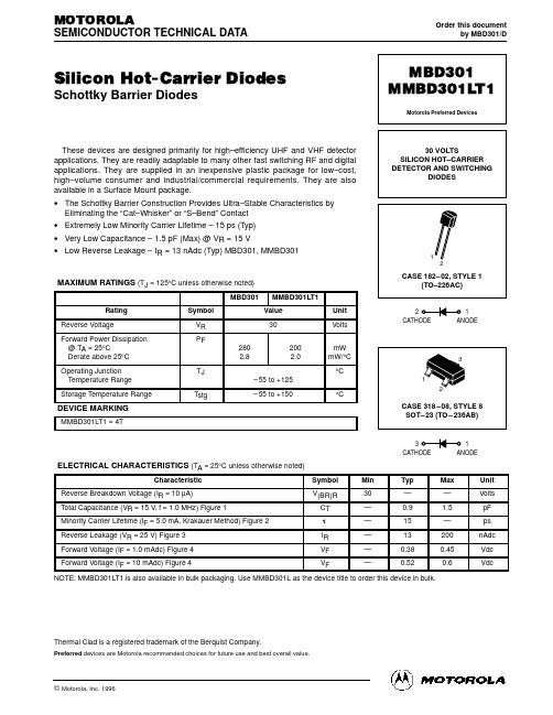
Silicon Hot-Carrier DiodesSchottky Barrier DiodesThese devices are designed primarily for high–efficiency UHF and VHF detector applications. They are readily adaptable to many other fast switching RF and digital applications. They are supplied in an inexpensive plastic package for low–cost,high–volume consumer and industrial/commercial requirements. They are also available in a Surface Mount package.•The Schottky Barrier Construction Provides Ultra–Stable Characteristics by Eliminating the “Cat–Whisker” or “S–Bend” Contact •Extremely Low Minority Carrier Lifetime – 15 ps (Typ)•Very Low Capacitance – 1.5 pF (Max) @ V R = 15 V•Low Reverse Leakage – I R = 13 nAdc (Typ) MBD301, MMBD301MAXIMUM RATINGS (T = 125°C unless otherwise noted)DEVICE MARKINGELECTRICAL CHARACTERISTICS (T = 25°C unless otherwise noted)NOTE:MMBD301LT1 is also available in bulk packaging. Use MMBD301L as the device title to order this device in bulk.Thermal Clad is a registered trademark of the Berquist Company.Order this documentby MBD301/DMOTOROLASEMICONDUCTOR TECHNICAL DATAMBD301MMBD301LT1Motorola Preferred Devices3130 VOLTSSILICON HOT–CARRIER DETECTOR AND SWITCHINGDIODES21元器件交易网元器件交易网MBD301 MMBD301LT1元器件交易网MBD301 MMBD301LT1How to reach us:USA/EUROPE: Motorola Literature Distribution; JAPAN: Nippon Motorola Ltd.; T atsumi–SPD–JLDC, T oshikatsu Otsuki,P.O. Box 20912; Phoenix, Arizona 85036. 1–800–441–24476F Seibu–Butsuryu–Center, 3–14–2 T atsumi Koto–Ku, T okyo 135, Japan. 03–3521–8315MFAX: RMFAX0@ – TOUCHTONE (602) 244–6609HONG KONG: Motorola Semiconductors H.K. Ltd.; 8B T ai Ping Industrial Park,INTERNET: http://Design–51 Ting Kok Road, T ai Po, N.T., Hong Kong. 852–26629298。
MAX9022中文资料

o No Phase Reversal for Overdriven Inputs
o Space-Saving Packages 5-Pin SC70 (MAX9021) 8-Pin SOT23 (MAX9022) 8-Pin µMAX (MAX9022) 14-Pin TSSOP (MAX9024)
MAX9024
14 OUTD 13 IND12 IND+ 11 VSS 10 INC+ 9 INC8 OUTC
TSSOP/SO
Rail-to-Rail is a registered trademark of Nippon Motorola, Ltd.
________________________________________________________________ Maxim Integrated Products 1
Input Offset Voltage Temperature Coefficient
SYMBOL VDD IDD VOS
CONDITIONS Guaranteed by PSRR test
(Note 2)
TCVOS
MIN TYP MAX UNITS
2.5
5.5
V
2.8
5
µA
±1
±8
mV
±1
µV/°C
Features
o Low-Cost Solution Available in Space-Saving SC70 Packages (Half the Size of SOT23)
o Low 2.8µA Supply Current
8205a中文资料
8205a中文资料锂电池保护板根据使用的不同IC和电压具有不同的电路和参数。
常用的保护IC是8261,DW01 +,CS213,GEM5018等。
其中,精工的8261系列具有更好的精度,当然价格也更昂贵。
后者全部在台湾制造。
国内二级市场主要使用DW01 +和CS213。
以下是带有MOS管8205A(8pin)的DW01 +的说明:锂电池保护板的正常工作流程为:当电池电压在2.5V至4.3V之间时,DW01的第一引脚和第三引脚均输出高电平(等于电源电压),第二引脚电压为0V。
此时,DW01的引脚1和3的电压将分别施加到8205A的引脚5和4。
由于8205A中的两个电子开关的G 极连接到DW01的电压,因此它们处于导通状态。
两个电子开关均处于打开状态。
此时,电池单体的负极直接连接至保护板的P-端子,并且保护板具有电压输出。
2.保护板过放电保护控制原理:当电池通过外部负载放电时,电池电压将缓慢降低,与此同时,DW01将通过R1电阻实时监控电池电压。
当电池电压降至约2.3V时,DW01将认为电池电压处于过放电电压状态,引脚1的输出电压立即断开,从而引脚1的电压变为0V,并且开关由于引脚5上没有电压,因此8205A中的电子管关闭。
此时,电池单元的B-和保护板的P-处于断开状态。
即,电池单元的放电电路被切断,并且电池单元将停止放电。
保护板处于过放电状态,并且已经维护。
保护板的P 和P-具有间接充电电压后,DW01通过B-检测到充电电压后,将立即停止过放电状态,并再次在引脚1上输出高电压以开启过放电控制8205A中的电子管。
也就是说,电池单元的B-和保护板的P-被重新连接,并且电池由充电器直接充电。
3.保护板过充保护控制原理:当电池由充电器正常充电时,随着充电时间的增加,电池的电压将越来越高。
当电池电压升至4.4V时,DW01将认为电池电压处于过充电电压状态。
然后立即断开引脚3的输出电压,以使引脚3的电压变为0V,并且由于引脚4上没有电压,因此8205A中的开关管被闭合。
U-901,U-902电能质量分析仪用户手册_4.5_CH

Unipower AB
Copyright (c) UNIPOWER AB Alingsås, Sweden 2006 E-mail: Internet:
注: 北京华辉奥特科技有限公司是瑞典联合电力公司系列产品在中国大陆的总代理,本用户手册由北京华辉公司按原文翻译,若有歧义,以 原文为主。以后若有更改,恕不另行通知,敬请用户及时浏览本公司的网站信息。 单位:北京华辉奥特科技有限公司 地址:北京西三环中路 18 号万发大厦 502 电话:010-63964018,63964019 传真:010-63964178 网址: 邮件:support@
Unilyzer 902 / 901
用户手册
中文版 4.5
UNIPOWER
用户手册 Unilyzer 902 / 901
UNIPOWER
用户手册 Unilyzer 902/ 901介绍 现在,数量越来越多的非线性负载例如电脑、办公设备和频率转换设备接入到电网之中。这 类电器设备对电网中的电能质量造成不好的影响,同时,往往这些设备对电网中的干扰也较 老型设备更加敏感。 由此产生了对先进便携式电能质量测量仪器的需求。现代电力工程师繁忙而实际的工作对测 量仪器提出了另一项重要的需求,即:易于操作!电能质量测量仪器必须简单、直观、易于 安装,方便取得测量结果,从而制订如何改善电能质量的行动计划。 Unilyzer 902 / 901 采用防尘防雨的 IP65 封装,是户外型仪表,可以测量所有电能质量参数, 包括长时间同时测量塌陷/浪涌和瞬变。Unilyzer 902 / 901 的设计适合任何电网场合,例如供 电分局、远程通信设施、工厂和商业建筑等。Unilyzer 902 / 901 为满足新的通信趋势要求,设 置了多种通信选择,可以用普通的 RS-232,内置调制解调器(选件)或以太网(选件)。这 样的设计使 Unilyzer 902 / 901 既是便携式电能质量分析仪,又可作为在线式电能质量监测仪 (它与在线式电能质量监测仪 UP-2210 使用了同样的监测系统软件),这充分体现了“便携 仪器是在线监测系统的补充”理念。 祝贺您选择了我们的 Unilyzer 902 / 901!如果您对我们的仪表有任何问题,请直接联系我们或 向我们的本地代表处询问。 顺颂商祺, 瑞典联合电力公司
Fluke 902_用户手册中文版(钳表)

有限担保和有限责任
本产品自购买之日起,将可享受三年材料上及工艺上的质 保,本担保不适用于保险丝,一次性电池,或由于意外、疏 忽、误用、改装、污染及非正常操作或处理引起的损坏。经 销商无权以 Fluke 的名义给予其它任何担保。如在保修期内 需要保修服务,请与您就近的 Fluke 授权服务中心联系, 获得产品退还授权 信息;然后将产品寄至该服务中心,并附 上产品问题描述。
交流和直流电压测量....................................... 10 电阻与通断 ..................................................... 11 微安 µA测量 ................................................... 12 温度................................................................ 13 电容................................................................ 16 交流电流测量 ................................................. 16 背照灯 ............................................................ 18 MIN MAX(最小值最大值)记录模式............. 18 显示保持......................................................... 19 自动关闭......................................................... 19 维护 .................................................................. 20 清洁钳表......................................................... 20 更换电池......................................................... 21 技术指标 ........................................................... 23 电气指标......................................................... 23 一般指标......................................................... 24
MP902技术规格书

MP902产品技术规范版本V ersion:V1.00发布日期Date:18/4/2008文件编号Document Number:xxxx深圳梦网科技发展有限公司本文档适用的产品是MP902彩信监控器。
本文档以MP902产品为例,主要介绍MP902产品的外观、硬件结构、功能、技术规格和模块有关指标的测试标准,用于帮助市场技术支持工程师提供技术支持及测试人员测试提供参考。
阅读对象本文档主要适用于以下工程师:产品工程师市场技术支持工程师测试工程师修改记录修订记录累积了每次文档更新的说明。
最新版本的文档包含以前所有文档版本的更新内容。
文档版本V1.0 (2008-04-18)第一次正式发布。
目录1 产品简介 (1)2 缩略语 (1)3外观和结构 (2)4功能 (3)4.1主要功能定义 (3)5主要技术规格 (4)5.1通讯协议及技术指标 (4)5.2射频接收 (4)5.3遥控接收 (4)5.4天线 (4)5.5主要性能指标 (5)5.6待机时间 (5)5.7工作条件 (5)6可靠性测试标准 (6)6.1跌落实验 (6)6.2振动实验 (6)6.3低温运行实验 (6)6.4低温存储实验 (7)6.5高温运行实验 (7)6.6高温存储实验 (7)6.7高温高湿实验 (8)6.8高低温冲击实验 (8)7 EMC/EMI测试标准 (8)7.1静电放电试验(ESD) (8)7.2射频电磁场辐射抗扰性试验 (9)7.3电快速瞬变脉冲群抗扰性试验 (9)7.4雷击浪涌抗扰性试验 (10)7.5射频电磁场传导抗扰性试验 (10)7.6电压瞬时跌落和短时中断的抗扰性试验 (11)7.7辐射发射试验 (11)8引用标准 (11)9产品齐套 (12)1产品简介深圳梦网科技发展有限公司是一家生产GSM/CDMA无线终端产品的国内知名企业,是国内最早开发和批量生产GSM、CDMA无线终端产品的厂商,拥有多年的研发与生产经验。
V90-B1.1彩信监控器是利用图像移动侦测和被动红外人体感应技术,将监控现场的异常用摄像头拍摄下来,经图像压缩,再经GSM模块通过移动通信网的彩信服务、GPRS功能,将现场拍摄到的画面传输到指定用户手机、邮箱或互联网管理平台的无线监控设备。
DAC902中文资料

操作原理 该 DAC902 uses 架构的电流导引技术来实现快速开关和高更新率.内的单片 D 核心元素/ A 转换器是一个数 组分段电流源,其目的是为了提供全面的输出电流可达 20mA(见图 1).内部解码器的地址差电流开关每次 更新和 DAC 相应的输出电流是由督导所有要么输出电流总结波节,IOUTor IOUT .互补输出提供一个差分输出信号,从而提高了动态性能测试减少偶次谐波,共模信 号(噪声),双输出 信号的 peak-to-peak 摇摆两个因素,相较于单端工作.分割结构的结果会有很大的红眼,在干扰能源 tion, 提高了动态 perfor -曼斯(SFDR),和 DNL.的电流输出保持非常高的更大的输出阻抗比 200kΩ.满量程输出电 流的比例确定内部基准电压和外部(1.24V)电阻,RSET.由此产生的 IREF 内部乘以一个 32 因素产生一个有效 DAC 输出电流这可以从 2mA 到 20mA,的价值而定对 RSET.该 DAC902 分为数字和模拟部分,每一个是通过自身 的供电电源引脚.该数字部分包括边沿触发的输入锁存器和解码器的逻辑,而模拟部分包括电流租金及其相 关交换机的源数组, 参考电路.
VOUT= IOUT• RLOAD
(5)
VOUT= DAC902 是一种高速,digital-to-analog 转换(DAC)提供力所能及的一 12-bit 分解选项 Speed Plus 系列高性能转换器.具有引脚兼容性在系列成员,DAC908, DAC900,和 DAC904 提供元件选择选项为 8-, 10-,和 14-bit 分解分别.在此的 D / A 系列所有机型转换器支持在 165MSPS 过剩与更新率出色的动态性能,特别适合满 足多种应用的需求.该 DAC902 先进分割架构优化,以提供高无杂散动态范围(SFDR)单色调,以及多音信号,必要 时,对通信信号传输路径中使用-tion 系统.该 DAC902 具有较高的电流输出阻抗(200kΩ)一个 20mA 标称范围,输 出符合最多 1.25V.的差动输出端允许既是一个差分或单端模拟信号接口.紧密匹配的电流输出确保出色的动力性 能差分配置,可与实施变压器.利用一小几何 CMOS 过程中,单片 DAC902 可以运作,宽,单电源范围+2.7V 到+5.5V. 其低功耗在允许使用便携式和电池供电系统.可以进一步优化通过降低实现的可调输出电流全面的选择 对于在 DAC902,掉电不连续操作
罗宾康高压变频器中文

版本
1.8(902232)罗宾康
1-3
介绍空冷型完美无谐波用户手册
1
项目描述
输入电压允许误差额定输出时为标称值的
+10%, -5%
输入功率因数负载超过
10%时
0.95
输出线电压
2.4 kV, 3.3 kV, 4.16 kV, 4.8 kV, 6.0 kV, 6.6 kV,
输出频率漂移
±0.5%
速度范围 0.5-330 Hz(与电机有关)
过载能力与所安装单元的类型及设置有关
加速时间范围 0.5-3200秒(与负载有关)
1
图
1-4.典型的
4160V(左)和
6000V(右)完美无谐波变频器排列图
1.3.特性概述
完美无谐波变频器的特性如下:
.高效率
.功率单元自动监测
.高可靠性
.单元后备
.模块化结构
.串行通讯口
.浪涌吸收器
.报表处理能力
.光纤控制电路
.
1.0利用率电机)。事实上,
完美无谐波变频器消除了变频器引发的使电机发热的有害谐波。同时,变频器引发的转矩
脉动也被消除(即使在低速范围),因此降低了机械设备的应力,共模电压和
dV/dt产生
的应力也减至最小。图
1-3.为典型完美无谐波变频器的输出电流波形。
典型的相
输出电流
时间
6.1.简介
版本
1.8(902232)罗宾康
dac902
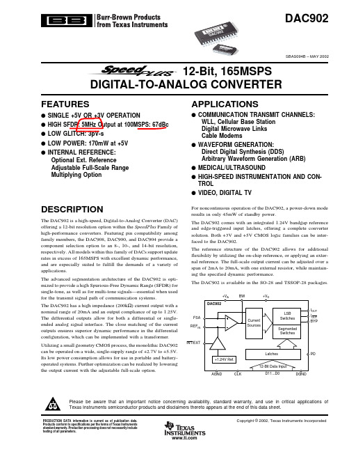
The advanced segmentation architecture of the DAC902 is optimized to provide a high Spurious-Free Dynamic Range (SFDR) for single-tone, as well as for multi-tone signals—essential when used for the transmit signal path of communication systems.
The DAC902 is available in the SO-28 and TSSOP-28 packages.
+VA DAC902
FSA REFIN
INT/EXT
BW
+VD
Current Sources
LSB Switches
Segmented Switches
I.24V Ref.
The DAC902 has a high impedance (200kΩ) current output with a nominal range of 20mA and an output compliance of up to 1.25V. The differential outputs allow for both a differential or singleended analog signal interface. The close matching of the current outputs ensures superior dynamic performance in the differential configuration, which can be implemented with a transformer.
17种新型彩电开关电源集成电路资料

17种新型彩电开关电源集成电路资料38[ ????? | 时间:2009-03-02 01:05:33 | 收藏本文] 【大中小】17种新型彩电开关电源集成电路资料 1、KA3S0680RFB KA3S0880RFB KA3S0680RFBKA3S0880RFB是日本FAIRCHILD公司生产的开关电源电路,内置功率MOSFET和控制电路,其内部设有过流、过压、过热保护电路,低压限制电路、高压感应电路等。
具有工作频率宽、效率高、工作稳定等特点,KA3S0680RFB 与KA3S0880RFB的内部电路基本相同,只是输出功率不同(KA3S0680RFB功率为150W;KA3S0880RFB功率为190W)。
它被应用在海信DP2999、海尔高美高等新型彩电中。
KA3S0680RFB KA3S0880RFB引脚功能与维修数据见表1所示。
引脚符号功能海信DP2999 海尔高美高对地电压()对地电阻(KΩ)对地电压(V)对地电阻(KΩ)红笔测罴笔测开机待机红笔测罴笔测① DRA IN 内置功率开关管漏极300 5.7 500 270 280 3.8 ∞ ② GND 接地0 0 0 0 0 0 0 ③ Vcc 电源 20 5 500 16 15 3.3 ∞ ④ FB 反馈1.8 8 200 200 0.2 5.7 200 ⑤ SYNC 同步输入 7.1 7.5 31 6.3 3.8 5.4 30 2、A5Q1265RF A5Q1265RF是日本FAIRCHILD公司生产的FPS型开关电源控制电路,内置具有耐压强650V的电流检测型场效应功率管和控制电路,并设有过流、过压、过热保护电路(当芯片表面温度超过150℃时,自动切断输出;当供电端③脚的电压高于24V或低于11V 时,芯片停止工作)。
它被应用在海尔UOC芯片新型彩电中。
A5Q1265RF引脚功能与维修数据见表2所示引脚符号功能海尔UOC 对地电压()对地电阻(KΩ)红笔测罴笔测① DRA IN 内部场效应管漏极270 3.7 +∞ ② GND 内部场效应管源极(接地)0 0 0 ③ Vcc 电源输入端16 3.3 +∞ ④ FB 反馈输入(通常接耦合器)1 5.6 200 ⑤ SYNC 同步输入 6.3 5.3 31 3、KA7630 KA7630是具有复位信号输出功能和三路电压输出的稳压器,其内部设有限流保护电路和过热保护电路;最大输入电压20V。
IC902
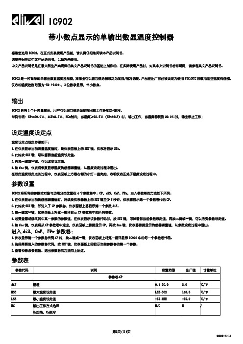
IC902带小数点显示的单输出数显温度控制器感谢您选用IC902。
在正式安装使用产品前,请认真仔细地阅读本产品说明书。
请妥善保存此中文产品说明书,以备将来使用。
中文产品说明书是在意大利生产商提供的英文产品说明书的基础上制作的,在实际使用产品时,对此中文说明书若有疑问,请参考英文产品说明书。
IC902是一种简单的单输出数显温度控制器,其输出可以很方便地被设定为加热/制冷功能。
产品在出厂时已被设定为使用PTC/NTC热敏电阻型温度传感器。
仪表的温度控制范围为-50~+140℃,3位数字显示,带小数点。
输出IC902具有1个开关量输出,用户可以很方便地设定输出的工作是加热/制冷。
举例说明:SEt=20.0℃、diF=2.5℃、HC=制冷,当温度≥22.5℃(SEt+diF)时,输出工作,当温度回复到20.0℃时,输出停止工作;设定温度设定点温度设定点设定步骤如下:1.在仪表显示当前测量温度值时,按仪表面板上的SET键,仪表将显示SEt。
2.此时按SET键,可以看到当前温度设定值。
3.再按︽键或︾键,可以改变设定值。
4.按fnc键,仪表将恢复显示温度传感器测量值,从温度设定过程中退出。
在设定温度设定点的过程中,仪表面板上方最右侧的小灯一直亮起,表明仪表正处于温度设定过程中。
参数设置IC902将所有的参数按对象与功能分类放置在4个参数卷中:CP、diS、CnF、FPr,进入参数卷的方法如下所列:1.在仪表显示当前传感器测量值时,持续按仪表面板上的SET键至少5秒钟,仪表将显示第一个参数卷代码CP。
2.此时按SET键,即进入了CP参数卷,仪表面板上将显示第一个参数diF。
3.按︽键或︾键,仪表面板上将逐一循环显示CP参数卷中的所有参数。
4.若要查看或修改其中某一参数的参数值,在仪表显示该参数代码时,按SET键,可以看到当前参数设定值,再按︽键或︾键,可以改变参数设定值。
5.按fnc键,仪表将从CP参数卷中退出,仪表面板上恢复显示CP,再按fnc键,仪表将恢复显示传感器测量值,从参数设定过程中退出。
RCS-902系列线路保护

电流变化量低定值起动元件动作仍进入正常运 行程序,当电流变化量高定值起动元件或零序 过流元件动作进入故障测量程序。
保护起动以后进入故障计算程序
总起动(CPU)与保护(DSP)的关系
+24V 总起动(CPU) BSJ +24V
TJ
各种继电器
(DSP)
RCS-902A 纵联保护的测量原理
1 方向距离继电器
RCS_902A(B、C、D)由距离方向零序方向继电器, 经通道交换信号构成全线路快速跳闸的方向保护,即 装置的纵联保护。 将按超范围整定的距离继电器构成方向比较元件,其 动作特性与距离保护基本一致,由低压距离继电器、 接地距离继电器、相间距离继电器组成
单重 三重 综重 停用
装置的总体方案及关键技术
RCS-900系列超高压线路保护在总结并 发展LFP-900线路保护先进的原理与技术和 成熟的运行经验的基础上,在硬件结构、 弱电保护、高阻接地选相、电流差动继电 器及辅助功能等方面作了较大改进,并有 所创新!
装置面板布置图
3×3键盘
运 行 电 A B C
RCS-902系列线路保护
RCS-902XF(M)线路保护配置
主
型 号 纵 联 保 护 欠 范 围
不延 时的 按欠 范围 整定 工频 变 化量 距离 距离 I段
要
功
能
重合闸
后 备 保 护 二段式相间和接 地距离 二段零序方向过 流(A型) 四段零序方向过 流(B型) 零序反时限过流 (D型)
RCS-902A 纵联方向距 RCS-902B 离元件 纵联零序方 向元件 RCS-902D
区号 取消
TV 断线
RCS-902A
OMEGA LE902系列线性编码器产品说明书
Conductivity Instrumentation, Dissolved Oxygen Instrumentation, Environmental Instrumentation, pH Electrodes and Instruments, Water and Soil Analysis Instrumentation
)ORZ DQG /HYHO
Air Velocity Indicators, Doppler Flowmeters, Level Measurement, Magnetic Flowmeters, Mass Flowmeters, Pitot Tubes, Pumps, Rotameters, Turbine and Paddle Wheel Flowmeters, Ultrasonic Flowmeters, Valves, Variable Area Flowmeters, Vortex Shedding Flowmeters
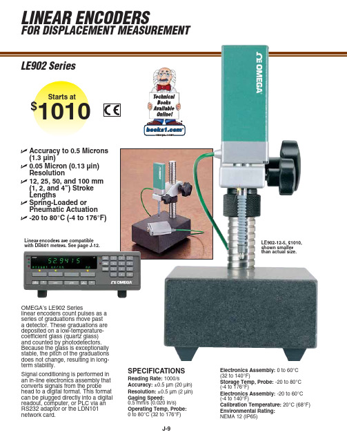
Signal conditioning is performed in an in-line electronics assembly that converts signals from the probe head to a digital format. This format can be plugged directly into a digital readout, computer, or PLC via an RS232 adaptor or the LDN101 network card.
2 m (6') cable
Clamping shank
18.8 (0.74)
- 1、下载文档前请自行甄别文档内容的完整性,平台不提供额外的编辑、内容补充、找答案等附加服务。
- 2、"仅部分预览"的文档,不可在线预览部分如存在完整性等问题,可反馈申请退款(可完整预览的文档不适用该条件!)。
- 3、如文档侵犯您的权益,请联系客服反馈,我们会尽快为您处理(人工客服工作时间:9:00-18:30)。
Low TCR, 1mWDual Rejustor™ Micro-ResistorMBD-472-ALInformation furnished by Microbridge Technologies is believed to be accurate and reliable. However, no responsibility is assumed by Microbridge Technologies for its use, nor for any infringements of patents or other rights of third parties that may result from its use. Specifications subject to change without notice. No license is granted by implication or otherwise under any patent or patent rights of Microbridge Technologies. Trademarks and registered trademarks are the property of their respective companies.The Rejustor is a precision, electrically-adjustable resistor from Microbridge. The Rejustor can be adjusted to a precision of 0.1%, or better. The Rejustor can be re-adjusted many times bi-directionally within the active range using standard hardware and LabVIEW-based Rejust-it calibration software.Low-power Rejustors are suitable for applications where the total power dissipation (in the pair) does not exceed 1mW.As a passive device, there is no warm-up period or boot-up time. Each Rejustor is independently adjustable to any value in the 30% adjustment range while still offering excellent TCR. They are non-volatile , maintaining their adjusted value indefinitely. Each Low-TCR Rejustor maintains 0ppm/K TCR across the adjustment rangewithin ±100ppm/K. Relative TCR between both Rejustors is less than ±50ppm/K.PARAMETERSPECIFICATIONResistance (as-manufactured) 4.7K Ω Minimum adjustable resistance 3.3K ΩAdjustment Precision 0.1% or 0.01%1TCR (per Rejustor)0±100ppm/K Power dissipation (per Rejustor) 0.5mWBENEFITSPrecision electrical in-circuit adjustment Externally adjust or calibrate parameters oncircuits or sensors at final assembly Adjustment process isolated from circuitallows true in-circuit calibrationSingle chip solution to calibrate voltages,currents, offsets, gains, etc.No mechanical moving parts – suitable for vibration sensitive applicationsImproved reliability; dependability; dust and moisture resistance over mechanical parts Dynamic adjustment provides cost and laborsavingsFlexibility reduces rework cost1Adjustment precision is limited by temperature control, accuracy of measurement and adjustment equipment and may increase adjustment timeELECTRICALLY ADJUSTABLE 4.7K Ω 1:1RESISTOR PAIRFigure 1: Functional Block DiagramFEATURESElectrically adjustable 4.7K Ω 1:1 dual resistor Passive, non-volatile variable resistor Adjustment range: 30% down from as-manufactured resistanceBi-directional adjustment within active range Long term stability 0.5%, see Table 5Flexibility: Potential for multiple adjustments Stable Temperature Coefficient as resistanceis adjusted – TCR: 0±100ppm/K Power Rating up to 1.0mW at 70o CSuitable for operation from -40 to +125o C,refer to Table 2Passive device, requires no power to operateor maintain adjustmentEasy to adjust with Rejust-it software andexternal DAC/ADC hardware Typical adjust times: ~ 1sec 1.APPLICATIONSAnywhere precision adjustment is required Gain and offset adjustmentReference voltage or current adjustment Precision Voltage Regulator adjustment Filter tuningRF Amplifier biasing Opto-electronicsFrequency Control devicesMechanical or digital potentiometerreplacementSuitable for high-frequency applicationsR1ADJR2R2ADJR2HGNDPIN CONFIGURATIONFigure 3: Pin Configuration, 16-pin QFN package (3x3mm)PIN FUNCTIONAL DESCRIPTIONTable 1: Pin Function DescriptionsMnemonicDescription16-Pin QFN Pin No.R1 Rejustor 1 Terminal 1 R1 Rejustor 1 Terminal 2 R2 Rejustor 2 Terminal 3 R2 Rejustor 2 Terminal 4 HGND Heater Ground 10 R2ADJ Rejustor 2 Adjust Input 11 R1ADJ Rejustor 1 Adjust Input 12NCNo Connect5, 6, 7, 8, 9, 13, 14,15, 16GENERAL OVERVIEWThe Microbridge Technologies Low TCR dual Rejustor family of electrically adjustable micro-resistors can be adjusted and matched to resistance values for precision control of sensors, voltage regulators, amplifiers and other applications. Rejustors are passive, non-volatile devices capable of being re-adjusted many times to very-high precision, bi-directionally; using only integrated circuit level electrical signals. Each Rejustor is independently adjustable to any ohmic value within a continuous range from the as-manufactured resistance to at least 70% of the as-manufactured value.Rejustors are a major improvement over thin-film laser trim and fusible link technologies at the wafer and chip level; as well as manual trim pots, digital potentiometers and thick-film laser trim at the hybrid and board level. Rejustors can be adjusted in-circuit to match any desired output condition using standard test equipment. Once adjusted, Rejustors maintain their precision indefinitely. Unlike laser trimming, the Rejustor can be adjusted up or down within the active adjustment range to facilitate rework or to enhance precision, for example, Rejustors can be used to iterate towards a final value.The Rejustor does not require active power. It is electrically isolated from both substrate and heater and can therefore float, electrically.Operation of the Rejustor die has been confirmed well beyond 100MHz. High-frequency performance of a packaged Rejustor is limited by the capacitance and inductance of the package.Rejustors can be adjusted using the low-cost MBK-408 Rejustor Calibration Tool from Microbridge or National Instruments based system or other suitable electronic test equipment. The adjustment process is controlled with Rejust-it software, which is based on LabVIEW and available as executable for a standard Windows-based PC.Available in16-pin QFN packages, Rejustors are RoHS and Pb-free and green compliant.NCNC NCNC NCNCNC NCTable 2: RATINGS – Rejustor R1 and R2 (4.7K Ω) Rejustors 0°C < T A < +70°C; unless otherwise noted.ItemConditions Typical Specifications Nominal Resistance R1 4,700Ω R1 Maximum Power 0.5mW Nominal Resistance R2 4,700Ω R2 Maximum Power0.5mW As specified in this datasheet0°C to +70°CAs specified in Application Note “RejustorOperating Guidelines for -40 to +125C Operation”-40 to +125oC Operating TemperatureBeyond -40 to +125oC Contact Microbridge Isolation Voltage (between any pins) Subject to power limits 25VTotal Resistance ToleranceAs-manufactured resistance is ±10% from nominalNominal Adjustment range+0 to -30% from as-manufactured Nominal Pair MatchingUnadjusted±2%Table 3: TCR CHARACTERISTICS – Rejustors Characteristics Specification (Worst Case)Test Method or ConditionsTemperature CoefficientUnadjusted Adjusted0±100ppm/K 0±100ppm/KChange in Temperature Coefficient± 50ppm/K TCR change in adjusted device relative to unadjusted device, by analysis Temperature Coefficient Matching of pairs± 10ppm/KAdjusted to match resistance, by analysis Rejustor Self-heating Coefficient of Resistance +4800 ppm/mW±20% Per Rejustor , unadjustedRelative Self-heating Coefficient of Resistance±100 ppm/mWWhen both Rejustors carry the same currentTable 4: PACKAGE ELECTRICAL CHARACTERISTICSCharacteristics Specification (Typical) Test Method or ConditionsQFN Capacitive Loading 0.7pF Per package pin, by analysis at 100MHz QFN Mutual Capacitance0.1pFBy analysis at 100MHz2Where indicated, drift specifications refer to resistance drift in the positive direction. Best performance is achieved at adjustments larger than 10% down from the as-manufactured resistance.Table 6: MANUFACTURABILITY DATA Characteristics Test Method or ConditionsESD Discharge JESD22-A114, human body model weakest pin pair, all lead combinations. Class 1ASolder abilityJESD22-A113, 235o C, slope 6ºC/secondPACKAGING OPTIONSTable 7: NOMINAL PACKAGE DIMENSIONSType Lead Count Body Width Body Length Lead Pitch Lead Width Lead Length Body Thickness JEDEC/ EIAJ QFN163.0mm3.0mm0.5mm0.25mm0.4mm0.85mmMO-220 (VEED)Figure 4: Package DimensionsTAPE CARRIER PACKAGINGFigure 5: Tape Carrier DimensionsAll dimensions in millimetersQFN-16 BOTTOM VIEWQFN-16 SIDETable 8: ORDERING INFORMATIONNOMINAL VALUES AVAILABLEThe following additional Micro Power Dual Rejustors are available with similar performance specifications. Consult the individual datasheet for more information.Please check with Microbridge Technologies Inc prior to design to ensure you have thelatest revision of the datasheet for this part3Where ZZZZ represents the 4-digit date code 4Smaller sample quantities available on tapePart Number Order CodePackage Part Marking 3Delivery QuantityMBD-472-AL111RQFN-16111R-ZZZZTape and Reel 30004Part Number Resistance R1 Value (Ω) Resistance R2 Value (Ω) Ratio QFN Order Code MBD-472-AL 4700 4700 1:1 111R MBD-472-CL 4700 24,500 1:5 1121 MBD-902-AL 9,000 9,000 1:1 111T MBD-902-CL 9,000 45,000 1:5 1127 MBD-902-XL 9,000 63,000 1:7 111X MBD-153-AL 15,000 15,000 1:1 111Y MBD-153-KL 15,000 45,000 1:3 111U MBD-333-AL33,00033,0001:1111Z。
