原相 鼠标 IC 3606 规格书
XX产品规格书(鼠标).doc
深圳雷柏科技股份有限公司企业文件Q/RAPOO XXXXX-XXXX产品规格书制定:审核:批准:XX产品规格书目次II修订记录 ..................................................................................1 产品描述 (1)1.1 产品概述(前期填写) (1)1.2 产品特性(前期填写,结构,电子,软件) (1)2 硬件规格 (1)2.1 外观规格(中期填写) (1)2.2 环境规格 (2)2.3 主要部件规格 (2)2.4 机械性能(中期填写) (3)2.5 电子规格 (3)3 软件规格 (5)3.1 驱动情况(如无驱动,则不需要填写驱动软件规格)(前期填写) (5)3.2 驱动软件规格(中期填写) (5)4 系统需求(前期填写): . (6)4.1 W INDOWS 2000/XP/VISTA/7 (6)4.2 (6)5 认证 (6)5.1 认证需求(前期) (6)5.2 法规符合性(中期) (6)XX产品规格书修订记录序号版本修订内容修订人修订日期XX产品规格书XX产品规格书1产品描述1.1产品概述(前期填写)1.2产品特性(前期填写,结构,电子,软件)2硬件规格2.1外观规格(中期填写)2.1.1鼠标外观尺寸 : mm重量 :g2.1.2接收器外观尺寸 : mm重量 :g2.2环境规格2.2.1使用环境(中后期填写)工作温度储存温度工作湿度储存湿度2.2.2可用电压范围(中期填写)RAPOO-R-Rev:A.1 XX产品规格书-5~ +45 ℃-40 ~ +70 ℃10~90%RH5~95%RH参数最小最大单位输入 (Tx)V 2.3主要部件规格2.3.1鼠标(前期填写)RAPOO-R-Rev:A.1XX产品规格书部件名称规格上盖,底盖,侧键装饰条滚轮脚垫线材(有线)其他(如有请写明)PCB 规格(中期填写)MCU 型号RF 型号传感器型号2.3.2接收器(前期填写)部件名称规格外壳塑件USB 接头表面处理(中期)PCB 规格RF IC 型号2.4机械性能(中期填写)项目左键操作力右键操作力中键操作力其它按键(如有请写明)按键行程条件规格± gf 操作点处于按键± gf 中心± gf± gf± mm2.5电子规格2.5.1基本功能(前期填写)a)按键功能:左键,右键,中键b)低电压报警功能:XX产品规格书2.5.2鼠标主要性能参数(前期填写,工作电流中期填写)a)分辨率: dpi;b)最大追踪速度: inches/Sec ;c)最大加速度: G;d)图片处理能力:帧 / 秒;e)USB 报告率: Hz;f)工作电压: V,1*AA ;g)工作电流:省电设计,共 4 种模式:(工作电流应比实际值预留适当余量)工作模式(不按键s 后):静态模式(s 后):待机模式(s 后):睡眠模式(min 后):h)低电报警电压:i)指示灯 1 指示描述:j)指示灯 2 指示描述:k)指示灯 3 指示描述:2.5.3 RF 性能(前期填写)a)载波频率: 2402-2480MHz ;b)蓝牙标准:c)工作频道: 16;d)是否自动跳频:是;e)识别码: 65536 组;f)调制方式: GFSK ;g)操作距离和范围:米, 360 度(中期填写);h)RF 输出功率: dB ;i)RF 传输速率: Mbps ;j)灵敏度:2.5.4接收器规格(前期填写)a)接口类型: USB;b)电压: 5V DC;c)电流: mA(中期)。
Mouse 产品指南说明书

ENG: Install the software. PTB: Instale o software. FRA : Installez le logiciel. ITA: Installare il software. PTG: Instale o software. ESP: Instale el software.ENG: Insert the batteries into the mouse and then close the cover. See the ProductGuide.PTB: Insira as pilhas no mouse e feche a tampa. Consulte o Guia do Produto.FRA : Insérez les piles dans la souris et fermez le couvercle. Consultez le guide duproduit.ITA: Inserire le pile nel mouse e chiudere il coperchio. Consultare la Guida alprodotto.ENG: Connect the receiver to a USB port on your computer.PTB: Conecte o receptor a uma porta USB do computador.FRA : Connectez le récepteur à un port USB sur votre ordinateur.ITA: Inserire il ricevitore in una porta USB del computer.PTG: Introduza o receptor numa porta USB do computador.ESP: Conecte el receptor a un puerto USB del equipo.ENG: Position the wireless mouse and receiver as shown above.PTB: Posicione o mouse sem fi o e o receptor como mostrado acima.FRA : Positionnez correctement le récepteur et la souris sans fi l commeindiqué ci-dessus.ITA: Posizionare il mouse senza fi li e il ricevitore come indicato sopra.PTG: Posicione o rato sem fi os e o receptor da forma ilustrada acima.ESP: Coloque el mouse inalámbrico y el receptor como se muestra en el gráfi co.1 122w a r eENG: Microsoft® wireless mouse with receiverPTB: Mouse sem fi o da Microsoft® com receptorFRA : Souris sans fi l avec récepteur de Microsoft®ENG: Help is available with the software.PTB: É fornecida Ajuda com o software.FRA : Une aide est disponible avec le logiciel. ITA: La Guida in linea viene fornita con il software. PTG: Existe ajuda disponível para o software. ESP: El software incluye un sistema de ayuda.ENG: Troubleshooting: Follow the steps above to restore connection.PTB: Solução de problemas: siga as etapas acima para restaurar a conexão.FRA : Dépannage : suivez les étapes ci-dessus pour restaurer la connexion.ITA: Risoluzione dei problemi: seguire le indicazioni riportate sopra per ripristinare la connessione.PTG: Resolução de problemas: Siga os passos acima para restaurar a ligação. ESP: Solución de problemas: siga los pasos mostrados en el gráfi co para restaurar。
MiCOKit 硬件手册说明书
HED Documentation Working Group (HDWG) Andy Liu Track Number: MXCHIP Co., Ltd Version: 1.1 2017.7.3 Category: Reference Manual OpenMiCOKit硬件手册摘要(Abstract)本文档主要描述MiCOKit系列开发套件的硬件组成及各功能模块电路原理图,旨在为MiCO-IoT物联网开发者提供与硬件相关的技术参考。
适用对象(Suitable Readers)本文适合MiCOKit-3166以及相关扩展板,旨在让开发者在使用EMW3166时参考。
版本更新说明日期修改人版本更新内容2017-6-29 Andy Liu V1.0 1. 初始版本2017-7-3 杜松V1.1 增加第三章MiCOKit-3166扩展板详解内容目录MiCOKit硬件手册 (1)版本更新说明 (1)1.MiCOKit系列开发套件概述 (4)1.1.硬件 (4)1.2.软件 (5)1.3.开发者支持 (5)2.MiCOKit-3166主板详解 (6)2.1.电源 (7)B转UART (7)2.3.W I-F I模块型号 (8)2.3.1 MiCOKit-3166之Wi-Fi模块 (8)2.4.LED指示灯 (9)2.5.运行状态选择 (9)2.6.按键 (10)2.7.JTAG调试接口 (10)2.8.A RDUINO接口 (11)2.9.电路图 (12)3.MiCOKit-3166扩展板详解 (14)3.1.OLED显示屏 (15)3.2.RGB三色LED (15)3.3.环境传感器(选配) (16)3.4.九轴运动传感器(选配) (17)3.5.苹果认证芯片(选配) (17)3.6.距离、光照传感器 (18)3.7.温湿度传感器 (19)3.8.红外反射开关 (19)3.9.光照传感器 (20)3.10.微型直流电动机 (20)3.11.标准A RDUINO接口 (21)3.12.A RDUINO传感器接口 (21)3.13.UART接口 (22)图目录图 1.1 EMW3166开发套件 (4)图 2.1 主板功能模块示意图 (6)图 2.2 电源电路原理图 (7)图2.3 USB转UART部分电路原理图 (8)图2.4 USB转出来的串口 (8)图2.5 EMW3166模块 (9)图2.6 LED指示灯原理图 (9)图2.7 按键部分原理图 (10)图 2.8 JTAG接口部分原理图 (11)图 2.9 Arduino接口部分原理图 (11)图3.1 MiCOKit扩展板功能图 (14)图3.2 OLED显示屏电路原理图 (15)图 3.3 RGB驱动电路原理图 (16)图 3.4 P8913驱动时序图 (16)图 3.5 环境传感器电路原理图 (17)图 3.6 九轴运动传感器电路原理图 (17)图 3.7 苹果CP芯片电路原理图 (17)图 3.8 距离、光照检测电路原理图 (18)图 3.9 温湿度电路原理图 (19)图 3.10 DHT11时序图 (19)图 3.11 红外反射电路原理图 (20)图 3.12 光照传感器电路原理图 (20)图 3.13 直流电机电路原理图 (21)图 3.14 扩展板Arduino电路原理图 (21)图 3.15. Arduino传感器接口电路原理图 (21)图 3.16 UART接口电路原理图 (22)表目录表 2.1 工作模式选择 (10)1.MiCOKit系列开发套件概述MiCOKit EMW3166是上海庆科(MXCHIP)推出的基于物联网操作系统(MiCO)系列开发套件,可用于物联网、智能硬件的原型机开发。
Modicon TM3AM6产品数据手册说明书

i s c l a i me r : T h i s d o c u m e n t a t i o n i s n o t i n t e n d e d a s a s u b s t i t u t ef o r a n d i s n o t t o b e u s e d f o r d e t e r m i n i ng s u i t a b i l i t y o r r e l i a b i l i t y o f th e s e p r o d u c t s f o r s p e ci f i c u s e r a p p l i c a t i o n sMainRange of productModicon TM3Product or component typeInput/Output analog module Range compatibility Modicon M251Modicon M241Modicon M221Analogue input number 4Analogue input type Current, analogue input range: 4...20 mACurrent, analogue input range: 0...20 mAVoltage, analogue input range: 0...10 VVoltage, analogue input range: - 10...10 VAnalogue output number 2Analogue output type4...20 mA current0...20 mA current0...10 V voltage- 10...10 V voltage ComplementaryAnalogue input resolution11 bits + sign 12 bits Permissible continuous overload13 V voltage 40 mA current Input impedance<= 50 Ohm current >= 1 MOhm voltage Analogue output resolution11 bits + sign 12 bits LSB value 2.44 mV, analogue input: 0...10 V voltage4.88 mV, analogue input: - 10...10 V voltage4.88 µA, analogue input: 0...20 mA current3.91 µA, analogue input:4...20 mA currentLoad type ResistiveLoad impedance ohmic1 kOhm voltage300 Ohm currentOutput ripple20 mVCross talk<= 1 LSB[Us] rated supply voltage24 V DCSupply voltage limits20.4...28.8 VType of cable<= 30 m twisted shielded pairs cable for input/output circuitCurrent consumption45 mA at 5 V DC (no load) via bus connector55 mA at 5 V DC (full load) via bus connector55 mA at 24 V DC (no load) via external supply100 mA at 24 V DC (full load) via external supplyLocal signalling 1 LED green for PWRElectrical connection10 x 1.5 mm² removable screw terminal block with pitch 3.81 mm adjustment for inputs10 x 1.5 mm² removable screw terminal block with pitch 3.81 mm adjustment for inputs, outputs andsupplyInsulation500 V AC between output and internal logic500 V AC between input and internal logic1500 V AC between input and supply1500 V AC between output and supplyMarking CESurge withstand 1 kV for power supply with common mode protection conforming to EN/IEC 61000-4-50.5 kV for power supply with differential mode protection conforming to EN/IEC 61000-4-51 kV for I/O with common mode protection conforming to EN/IEC 61000-4-50.5 kV for I/O with differential mode protection conforming to EN/IEC 61000-4-5Mounting support Top hat type TH35-15 rail conforming to IEC 60715Top hat type TH35-7.5 rail conforming to IEC 60715Plate or panel with fixing kitHeight90 mmDepth70 mmWidth23.6 mmProduct weight0.11 kgEnvironmentStandards EN/IEC 61131-2EN/IEC 61010-2-201Resistance to electrostatic discharge 4 kV on contact conforming to EN/IEC 61000-4-28 kV in air conforming to EN/IEC 61000-4-2Resistance to electromagnetic fields10 V/m at 80 MHz...1 GHz conforming to EN/IEC 61000-4-33 V/m at 1.4 GHz...2 GHz conforming to EN/IEC 61000-4-31 V/m at2 GHz...3 GHz conforming to EN/IEC 61000-4-3Resistance to magnetic fields30 A/m at 50...60 Hz conforming to EN/IEC 61000-4-8Resistance to fast transients 1 kV I/O conforming to EN/IEC 61000-4-4Resistance to conducted disturbances, induced by radio frequency fields 10 V at 0.15...80 MHz conforming to EN/IEC 61000-4-63 V at spot frequency (2, 3, 4, 6.2, 8.2, 12.6, 16.5, 18.8, 22, 25 MHz) conforming to Marine specification (LR, ABS, DNV, GL)Electromagnetic emission Radiated emissions, test level: 40 dBμV/m QP class A (10 m at 30...230 MHz) conforming to EN/IEC55011Radiated emissions, test level: 47 dBμV/m QP class A (10 m at 230 MHz...1 GHz) conforming to EN/IEC 55011Immunity to microbreaks10 msAmbient air temperature for operation-10...55 °C (horizontal installation)-10...35 °C (vertical installation)2Offer Sustainability Sustainable offer statusGreen Premium product RoHS (date code: YYWW)Compliant - since 1415 - Schneider Electric declaration of conformity Schneider Electric declaration of conformity REAChReference not containing SVHC above the threshold Reference not containing SVHC above the threshold Product environmental profile Available Product environmental Product end of life instructionsAvailableEnd of life manual(*)8.5 mm/0.33 in when the clamp is pulled out.Incorrect Mounting(1)Install a mounting strip Mounting Hole LayoutWiring Diagram (Current / Voltage)(*)Type T fuse (1)Current/Voltage analog output device (2)Current/Voltage analog input device。
Quectel_M26-OpenCPU_硬件设计手册_V1.0
2 综述 ...................................................................................................................................................... 11
3.5.1. 主串口............................................................................................................................. 34
本文档手册版权属于移远公司,任何人未经我公司复制转载该文档将承担法律责任。
Q n 版权所有 ©上海移远通信技术有限公司 2014,保留一切权利。 Confide Copyright © Quectel Wireless Solutions Co., Ltd. 2014
上海移远通信技术有限公司
1 / 81
如需技术支持或反馈我司技术文档中的问题,可随时登陆如下网址: /support/techsupport.aspx
l 前言
移远公司提供该文档内容用以支持其客户的产品设计。客户须按照文档中提供的规范,参数来设计其产品。
te 由于客户操作不当而造成的人身伤害或财产损失,本公司不承担任何责任。在未声明前,移远公司有权对 c l 该文档规范进行更新。 ue tia 版权申明
Q n 3.2.2. 关机 ................................................................................................................................ 26 3.2.2.1. PWRKEY 引脚关机............................................................................................ 26 e 3.2.2.2. API 函数关机...................................................................................................... 27 fid 3.2.2.3. 低压自动关机 ..................................................................................................... 27 3.2.3. 推荐的系统开关机电路 ................................................................................................... 28 3.3. 省电技术 ................................................................................................................................ 29
Agilent ADNK-3061 光学鼠标设计师套件概述说明书

Agilent ADNK-3061Optical Mouse Designer’s KitProduct OverviewDescriptionAgilent Technologies and Cypress Semiconductor have joined forces again to produce a new optical mouse reference design kit. Based on the new Agilent ADNS-3060 high performance optical mouse sensor and the powerful Cypress CY7C63743-PC enCoRe™ USB microcontroller, this reference design kit provides a low cost feature-rich solution in one neat package.The Agilent ADNS-3060 optical mouse sensor, a 20-pin staggered dual inline package (DIP), is based on a new, faster architec-ture with improved navigation performance. It is able to mea-sure changes in position by optically acquiring sequential surface images of over 6400 fps and mathematically determining the direction and magnitude of movement.The ADNS-3060 along with the ADNS-2120 lens, ADNS-2220 clip and HLMP-ED80-XX000 form a complete, compact optical mouse tracking system. There are no mechanical parts, which means high reliability and less mainte-nance for the end user. In addi-tion, precision optical alignmentis not required, facilitating highvolume assembly. The sensor isprogrammed via registersthrough a four-wire serial port.The Cypress CY7C63743-PCenCoRe is a revolutionary chipthat integrates numerous com-mon components, includingbreakthrough crystal-less oscilla-tor. The result is an overallreduction in board componentsand reduced system cost. TheEPROM based microcontrollerallows easy firmware modifica-tion, as well as storage of Vendorand Product ID™s without anexternal EEPROM.This kit is connectable to a PCvia the USB or PS/2 ports. Asingle cable with a USB connec-tor and a PS/2 adapter is alsoprovided. The design automati-cally detects the type of interfaceis attached, allowing furtherdevelopment of a USB or PS/2only mouse.Features•Complete optical mouse referencedesign kit•ADNS-3060 high performanceoptical mouse sensor•High speed motion detection – upto 40 ips and 15g•New architecture for greatlyimproved optical navigationtechnology•No mechanical moving parts foreasy maintenance and highreliability•Programmable frame rate over6400 frames per second•SmartSpeed self-adjusting framerate for optimum performance•Serial port burst mode for fast datatransfer•400 or 800 cpi selectable resolution•Single 3.3 volt power supply•Four-wire serial port along withChip Select, Power Down, andReset pins•Cypress enCoRe™ CY7C63743-PCUSB controller•USB and PS/2 interface combina-tion for PC connection•Proprietary 8-bit RISC processor,USB and PS/2-optimized interfacefor high system performance•8K Bytes of internal EPROMprovided to enable easycustomization of firmware andlower cost•Conforms to USB suspend modespecificationsFigure 1. Circuit-level block diagram for ADNK-3061 designer ’s kit optical mouse using the Agilent ADNS-3060 optical mouse sensor and Cypress CY7C63743-PC enCoRe USB Controller.Figure 2. Sectional view of PCB assembly highlighting all optical mouse components (optical mouse sensor, clip, lens, LED, PCB, and base plate).SurfaceBase PlateLens/Light Pipe SensorClipLEDPCBVcc D +D -GNDSHLD(Optional)187Ω 1/8 WKit ComponentsThe designer’s kit contains components as follows:Part Number Description Name Quantity ADNS-3060Solid-State Optical Mouse Sensor Sensor5CY7C63743-PC Cypress USB Controller USB Controller5ADNS-2120Round Lens Plate Lens5ADNS-2120-001Trim Lens Plate Lens5ADNS-2220LED Assembly Clip (Black Clip)LED Clip5ADNS-2220-001LED Assembly Clip (Transparent)LED Clip5HLMP-ED80-XX000639 nm T 1 _ (5 mm) Diameter LED LED5ADNK-3061 CD Includes Documentation and Support Files for ADNK-30611Documentation•ADNS-3060 Data Sheet•CY7C63743-PC Data Sheet•ADNS-2120 Data Sheet•ADNS-2220 Data Sheet•HLMP-ED80-XX000 LED Data Sheet•AN 5035 – PCB Mounting Method for ADNS-3060 Optical Sensor•AN 5034 – ADNS-3060 Power Saving Methodology•AN 5036 – ADNS-3060 Eye Safety CalculationsHardware Support Files•ADNK-3061 BOM List•ADNK-3061 Schematic•IGES Base Plate Feature File•Gerber FileSoftware Support Files•Microcontroller FirmwareCypress LAB™ Support Files•CY Debugger•CYASM Assembler Software•Code Examples•User ManualADNK-3061 Mouse High Performance Reference Design Mouse Optical Mouse1Ordering InformationFor ordering information, please contact your local Agilent sales representative.At Cypress call (800) 541-4736 or (408) 943-2821 or visit the web site at At Agilent call (800) 235-0312, visit the website at /semiconductors or mail your queries at ********************************/semiconductorsFor product information and a complete list of distributors, please go to our web site.For technical assistance call:Americas/Canada: +1 (800) 235-0312 or (916) 788-6763Europe: +49 (0) 6441 92460China: 10800 650 0017Hong Kong: (65) 6756 2394India, Australia, New Zealand: (65) 6755 1939Japan: (+81 3) 3335-8152(Domestic/International), or 0120-61-1280(Domestic Only)Korea: (65) 6755 1989Singapore, Malaysia, Vietnam, Thailand, Philippines,Indonesia: (65) 6755 2044Taiwan: (65) 6755 1843Data subject to change.Copyright © 2004 Agilent Technologies, Inc.November 8, 20045989-0688ENFor product information and a complete list of distributors, please go to our website.For technical assistance call:Americas/Canada: +1 (800) 858-1810 or (408) 943-2600Europe (France or Germany): 33-1-69-29-88-90 or 49-8106-24480China: 86-21-6391-5233Hong Kong: 852-2420-2568Japan: 81-6-6532-6738South Korea: 82-2-562-7005Singapore: 65-6735-0338Taiwan: 866-2-2725-5515/support。
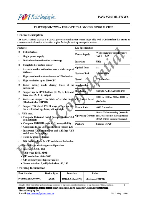
原相 鼠标 IC 3509 规格书
2
專利公示:本產品業經本公司獲得台灣專利第 509867, 530489, 529309, 560179, 526662, 554497, I230890, I287732 號專利在案。
PixArt Imaging Inc.
E-mail: fae_service@
V1.0 May. 2010
Oscillator output. Oscillator input. CPI switch input and indication (PWM) output. Button left key input. Mechanical(L)/IRPTR(H) trapping input and IRPTR power control output. Chip power VDD 5.0V. Chip ground. I/O voltage reference output. Analog voltage reference output. USB D+. USB D-. Button right key input. Button middle key input. LED control. Z-axis mechanical / IRPTR scroller input. Z-axis mechanical / IRPTR scroller input. Tilt wheel button left key input. Button 5th key input. Button 4th key input.
Interface
Roller
PAW3509DH-TXWA
4D5B
USB (LS,16-bitXY) Mechanical/IRPTR
All rights strictly reserved any portion in this paper shall not be reproduced, copied or transformed to any other forms without permission.
XX产品规格书(鼠标)
深圳雷柏科技股份有限公司企业文件 Q/RAPOO XXXXX-XXXX产品规格书制定:审核:批准:目次修订记录 (II)1产品描述 (1)1.1产品概述(前期填写) (1)1.2产品特性(前期填写,结构,电子,软件) (1)2硬件规格 (1)2.1外观规格(中期填写) (1)2.2环境规格 (2)2.3主要部件规格 (2)2.4机械性能(中期填写) (3)2.5电子规格 (3)3软件规格 (5)3.1驱动情况(如无驱动,则不需要填写驱动软件规格)(前期填写) (5)3.2驱动软件规格(中期填写) (5)4 系统需求(前期填写): (6)4.1W INDOWS 2000/XP/VISTA/7 (6)4.2 (6)5认证 (6)5.1认证需求(前期) (6)5.2法规符合性(中期) (6)修订记录序号版本修订内容修订人修订日期XX产品规格书1 产品描述1.1产品概述(前期填写)1.2产品特性(前期填写,结构,电子,软件)2硬件规格2.1 外观规格(中期填写)2.1.1鼠标⏹外观尺寸: mm⏹重量: g2.1.2接收器⏹外观尺寸: mm⏹重量: g2.2环境规格2.2.1使用环境(中后期填写)工作温度-5~ +45℃储存温度-40 ~ +70℃工作湿度10 ~ 90 % RH储存湿度 5 ~ 95 % RH2.2.2可用电压范围(中期填写)参数最小最大单位输入(Tx) V 2.3主要部件规格2.3.1鼠标(前期填写)部件名称规格上盖,底盖,侧键装饰条滚轮脚垫线材(有线)其他(如有请写明)PCB 规格(中期填写)MCU 型号RF 型号传感器型号2.3.2接收器(前期填写)部件名称规格外壳塑件USB 接头表面处理(中期)PCB 规格RF IC型号2.4机械性能(中期填写)项目条件规格左键操作力操作点处于按键中心±gf右键操作力±gf中键操作力±gf其它按键(如有请写明)±gf按键行程±mm 2.5电子规格2.5.1基本功能(前期填写)a)按键功能:左键,右键,中键……b)低电压报警功能:2.5.2鼠标主要性能参数(前期填写,工作电流中期填写)a)分辨率:dpi;b)最大追踪速度:inches/Sec;c)最大加速度:G;d)图片处理能力:帧/秒;e)USB报告率:Hz;f)工作电压:V,1*AA;g)工作电流:省电设计,共4种模式:(工作电流应比实际值预留适当余量)工作模式(不按键s后):静态模式(s后):待机模式(s后):睡眠模式(min后):h)低电报警电压:i)指示灯1指示描述:j)指示灯2指示描述:k)指示灯3指示描述:2.5.3 RF性能(前期填写)a) 载波频率:2402-2480MHz;b) 蓝牙标准:c) 工作频道:16;d) 是否自动跳频:是;e) 识别码:65536组;f) 调制方式:GFSK;g) 操作距离和范围:米,360度(中期填写);h) RF输出功率:dB;i) RF传输速率:Mbps;j) 灵敏度:2.5.4接收器规格(前期填写)a)接口类型:USB;b)电压:5V DC;c)电流:mA(中期)。
A2636 中文数据手册 V0.7

,3
Z2
4
L
5
M
6
R
7
பைடு நூலகம்OPT
8
LED
9
PS2_DATA
10
PS2_CLK
11
AVDD
12
VDD5V
A2636
3D U+P CMOS 光学鼠标单芯片
I/O
描叙
_
电源地
I
Z轴输入1
I
Z轴输入2
I
左键
I
中键
I
右键
I/O
DPI设置脚
O
LED 驱动
I/O
USB D- 或者 PS/2 数据
I/O
USB D+ 或者 PS/2 时钟
版本:0.7
3/10
2008 年 8 月 29 日
A2636
3D U+P CMOS 光学鼠标单芯片
6. 电气参数
标识符
IDD
VIL1 VIH1
VIL2 VIH2
VIL3 VIH3 VPOR IOL1
描叙
工作状态下的消耗电流e
待命状态下的消耗电流 输入输出口低电平 输入输出口高电平
USB输入输出口低电平 USB输入输出口高电平
最小 值
0 4.5
2000 2.3 0
典型 值
5.0
2.4
800
最大值
40 5.5 100 4000 2.5 24 16 1600
单位
摄氏度 伏 毫伏
帧/秒 毫米 英寸/秒
g 点/英寸
注解 800或者1600
___________________________________________________________________________________________
LB-360中文规格书最新2012.10.13
0.1V
B) TEMPERATURE NORMAL OPERATING RANGE EXTENDED OPERATING RANGE -20 C -20 C
o o
TO TO
40 C 50 C
o
O
Specification 规格
1)DEFAULT SETTING:
Frequency Table(频段): 2402-2480MHz
c)Reference Crystal Frequency 晶体频率
d) 1K MIC IN:参考样机 e) 300H MIC IN:参考样机
f) TX DISTORTION (With Audio Gateway)
3)RECEIVER ( PCBA )RX 接收测试
DESCRIPTION
a) BER(FER) 误码率 AT 0.1% b) SPK OUT 喇叭输出电平 1K (参考样机) SPK OUT 喇叭输出电平300Hz (参考样机) (MIC IN 179mV , With SPK Loading & Audio Gateway) c) DISTORTION AT SPK 接收失真 (MIC IN 179mV , With SPK Loading & Audio Gateway)
Center Frequency(中心频率(CH39)): 2441.000MHz 蓝牙版本 v3.0 system Bluetooth Chip: PAIRING CODE: CSR BC6145 0000
PAIRING TIMEOUT 配对状持续时间:300S
DEVICE NAME:
70 4.5 3.6 2.5
LIMIT
>60 >4 >3.5 <3
IC datasheet pdf-CAT3606 pdf,datasheet

CAT36066-Channel Low Noise Charge Pump White LED DriverDescriptionThe CAT3606 controls up to four LEDs for the main display and two LEDs for the sub-display in cellular phones. The device is capable of operating in either 1x (LDO) mode or 1.5x charge pump mode. All LED pin currents are regulated and tightly matched to achieve uniformity of brightness across the LCD backlight. An external resistor (R SET) sets the nominal output current.The device can deliver as much as 20 mA per channel during low voltage operation (3 V), and 30 mA per channel during nominal operation (3.3 V). A constant high-frequency switching scheme (1MHz) provides low noise and allows the use of very small value ceramic capacitors.A “zero” quiescent current mode can be achieved via the chip enable pin EN. The Main and Sub LEDs each have their own dedicated ON/OFF control pins ENM, ENS. Dimming can be achieved using either a DC voltage to control the R SET pin current, or by applying a PWM signal on the ENM and ENS pins.The device is available in a 16−pad TQFN package with a max height of 0.8 mm.Features•Drives up to 4 Main LEDs and 2 Sub LEDs•Separate Control for Main and Sub LEDs •Compatible with Supply V oltage of 3 V to 5.5 V•Power Efficiency up to 90%•Output Current up to 30 mA per LED•High−frequency Operation at 1 MHz•2 Modes of Operation 1x and 1.5x•White LED Detect Circuitry on All Channels •Shutdown Current less than 1 m A•Small Ceramic Capacitors•Soft Start and Current Limiting•Short Circuit Protection•16−pad TQFN Package, 0.8 mm Max Height•These Devices are Pb−Free, Halogen Free/BFR Free and are RoHS CompliantApplications•Cell Phone Main and Sub−display Backlight•Navigation •PDAs •Digital CamerasTQFN−16HV4 SUFFIXCASE 510AEPIN CONNECTIONS (Note 1)G366MARKING DIAGRAMSDevice Package ShippingORDERING INFORMATIONCAT3606HV4−T2TQFN−16(Note 2)2,000/Tape & ReelG366 = CAT3606HV4−T2CDBB = CAT3606HV4−GT21.The “exposed pad” under the package must beconnected to the ground plane on the PCB.2.Matte−Tin Plated Finish (RoHS−compliant).3.NiPdAu Plated Finish (RoHS−compliant).LED5LED4LED3LED2LED1C2+C2−C1−LED6ENENMENSRSETVOUTVINC1+1(4 x 4 mm) (Top View)CDBBCAT3606HV4−GT2TQFN−16(Note 3)GNDFigure 1. Typical Application Circuitm FLi −OUT Table 1. PIN DESCRIPTIONPin #Name Function1LED6LED6 cathode terminal2EN Enable/shutdown input, active high3ENM Enable “main” input for LED1 to LED4, active low 4ENS Enable “sub” input for LED5 and LED6, active low5RSET The LED output current is set by the current sourced out of the RSET pin 6VOUT Charge pump output connected to the LED anodes 7VIN Supply voltage8C1+Bucket capacitor 1 terminal 9C1Bucket capacitor 1 terminal 10C2Bucket capacitor 2 terminal 11C2+Bucket capacitor 2 terminal 12LED1LED 1 cathode terminal 13LED2LED 2 cathode terminal 14LED3LED 3 cathode terminal 15LED4LED 4 cathode terminal 16LED5LED 5 cathode terminal PADGNDGround referenceTable 2. ABSOLUTE MAXIMUM RATINGSParameter Rating Unit VIN, VOUT, LEDx voltage−0.3 to 7.0V EN, ENM, ENS voltage−0.3 to VIN V RSET voltage−0.3 to VIN V RSET current±1mA Ambient Temperature Range−40 to +85_C Storage Temperature Range−65 to +160_C Lead Temperature300_C ESD Rating HBM (Human Body Model)2,000V ESD Rating MM (Machine Model) (Note 4)200V Stresses exceeding Maximum Ratings may damage the device. Maximum Ratings are stress ratings only. Functional operation above the Recommended Operating Conditions is not implied. Extended exposure to stresses above the Recommended Operating Conditions may affect device reliability.4.Machine model is with 200 pF capacitor discharged directly into each pin.Table 3. RECOMMENDED OPERATING CONDITIONSParameter Range Unit VIN 3.0 to 5.5V Ambient Temperature Range−40 to +85_C Input/Output/Bucket Capacitors 1 ±20% Typical m FI LED per LED pin0 to 30mAI OUT Total Output Current0 to 150mA Table 4. ELECTRICAL OPERATING CHARACTERISTICS(Limits over recommended operating conditions unless specified otherwise. Typical values at T A = 25°C, V IN = 3.5 V, I RSET = 5 m A.) Symbol Parameter Conditions Min Typ Max UnitI Q Quiescent Current V EN= 0 V1x Mode, No Load1.5x Mode, No Load 0.10.32.6115m AmAmAV RSET RSET Regulated Voltage 1.17 1.2 1.23VI LED Programmed LED Current I RSET = 5 m AI RSET = 37 m AI RSET = 78 m A 2.415.030.0mAI LED LED Current Range with 6 LEDs 3.3 ≤ VIN ≤ 4.5 V3.0 ≤ VIN ≤4.5 V 3020mAI LED LED Current Range with 4 LEDs 3.3 ≤ VIN ≤ 4.5 V30mAI LED−ACC LED Current Accuracy0.5 mA ≤ I LED≤ 3 mA3 mA ≤ I LED≤ 30 mA ±15±5%I LED−DEV LED Channel Matching(I LED – I LEDAVG) / I LEDAVG±3%R OUT Output Resistance(Open Loop)1x Mode,1.5x Mode, I OUT = 100 mA1.46.52.510Wf OSC Charge Pump Frequency0.8 1.0 1.3MHz T DROPOUT1x to 1.5x Mode Transition Dropout Delay0.40.60.9ms I EN−CTR Input Leakage Current On Inputs EN, ENM, ENS1m AV EN−CTR High Detect ThresholdLow Detect Threshold On Inputs EN, ENM, ENS0.40.80.71.3VI SC Input Current Limit VOUT = GND304560mA I LIM Maximum Input Current VOUT > 1 V200400600mABlock DiagramFigure 2. CAT3606 Functional Block Diagramm FVBasic OperationAt power-up, the CA T3606 starts operation in 1x mode. If it is able to drive the programmed LED current, it continues in 1x mode. If the battery voltage drops to a level where the LED current cannot be met, the driver automatically switches into 1.5x mode, to boost the output voltage high enough to achieve the nominal LED current.The above sequence is reinitialized each and every time the chip is powered up or is taken out of shutdown mode (via EN pin). The use of the Main and Sub display enable pins (ENM or ENS) does not affect the mode of operation. LED Current SettingThe LED current is set by the external resistor R SET connected between the RSET pin and ground. Table 5 lists various LED currents and the associated R SET resistor value for standard 1% precision surface mount resistors.Table 5. RSET Resistor SelectionLED Current (mA)R SET (k W)1649228751021049.91532.42023.73015.4The enable lines ENM and ENS allow to turn On or Off a group of LEDs as shown in Table 6.Table 6. LED SelectionControl Lines LED Outputs EN ENM ENSMainLED1 − LED4SubLED5 −LED6 0X X––111––101ON−110−ON100ON ON NOTES:1 = logic high (or VIN)0 = logic low (or GND)– = LED output OFFX = don’t careThe unused LED channels can also be turned off by connecting the respective LED pins to VOUT. In which case, the corresponding LED driver is disabled and the typical LED sink current is only about 0.2 mA. When the following equation is true on any channel, the driver turns off the LED channel:VOUT*V LED v1V(LED channel OFF) Note: The CA T3606 is designed to drive LEDs with forward voltage greater than 1 V and is not compatible with resistive loads.Figure 3. Efficiency vs. Input Voltage(6 LEDs)Figure 4. Efficiency vs. Total LED Current(6 LEDs)INPUT VOLTAGE (V)TOTAL LED CURRENT (mA)405060708090100405060708090100Figure 5. LED Current vs. Input VoltageFigure 6. LED Current Change vs.TemperatureINPUT VOLTAGE (V)TEMPERATURE (°C)−−−0.51.5−−Figure 7. Ground Current vs. Input Voltage(1x Mode)Figure 8. Ground Current vs. Temperature(1x Mode)INPUT VOLTAGE (V)TEMPERATURE (°C)0.10.20.30.40.500.10.20.30.40.5E F F I C I E N C Y (%)E F F I C I E N C Y (%)L E D C U R R E N T C H A N G E (%)L E D C U R R E N T C H A N G E (%)G R O U N D C U R R E N T (m A )G R O U N D C U R R E N T (m A )01.0−−Figure 9. Ground Current vs. Input Voltage(1.5x Mode)Figure 10. Supply Current vs. Input VoltageINPUT VOLTAGE (V)INPUT VOLTAGE (V)134580120140Figure 11. Oscillator Frequency vs. InputVoltageFigure 12. Oscillator Frequency vs.TemperatureINPUT VOLTAGE (V)TEMPERATURE (°C)0.900.951.001.051.100.900.951.001.051.10Figure 13. Output Resistance vs. Input Voltage(1x Mode)Figure 14. Output Resistance vs. Input Voltage(1.5x Mode)INPUT VOLTAGE (V)INPUT VOLTAGE (V)1234246810G R O U N D C U R R E N T (m A )G R O U N D C U R R E N T (m A )C L O C K F R E Q U E N C Y (M H z )C L O C K F R E Q U E N C Y (M H z )O U T P U T R E S I S T A N C E (W )O U T P U T R E S I S T A N C E (W )2100Figure 15. Switching Waveforms in 1.5x Mode Figure 16. Operating Waveforms in 1x Mode400 nsec/div400 nsec/divCurrent Input 50mV/VIN 50mV/divVOUT Input 50mV/div VIN Figure 17. Power Up 6 LEDs at 15 mA,VIN = 3 V (1.5x Mode)Figure 18. Power Up 6 LEDs at 15 mA,VIN = 3.6 V (1x Mode)400 m sec/div400 m sec/div2V/divVOUT 2V/div EN 2V/divVOUT 100mA/divInput 2V/divEN Figure 19. LED Current vs. R SETFigure 20. Line Transient Responsein 1x ModeRSET (k W )200 m sec/div10,000100100.1101002V/div VOUT 5mA/div Input 1V/div3.6V to4.9VVinL E D C U R R E N T (m A )10mA/Input Current 100mA/divAC coupledCurrent 10mA/div AC coupledAC coupledVOUT 50mV/divdiv divCurrent Current 10001(V IN = 3.6 V, EN = V IN , ENM = ENS = GND, C IN = C OUT = 1 m F, T AMB = 25°C, unless otherwise specified.)Figure 21. Foldback Current Limiting OUTPUT CURRENT (mA)5004003002001000012345O U TP U T V O L T A G E (V )1x ModeFigure 22. RSET Pin Voltage vs. Temperature−50−2502550751001251.161.181.201.221.24R S E T P I N V O L T A G E (V )Figure 23. PWM Dimming at 1 kHz on ENM and ENS50mA/divCurrent Tot. LED 1V/divVOUT ENM & ENS5V/div200 m sec/divTEMPERATURE (°C)Recommended LayoutWhen the driver is in the 1.5x charge pump mode, the 1MHz switching frequency operation requires to minimize trace length and impedance to ground on all 4 capacitors. A ground plane should cover the area on the bottom side of the PCB opposite to the IC and the bypass capacitors.Capacitors Cin and Cout require short connection to ground which can be done with multiple vias as shown on Figure 24.A square copper area matches the QFN16 exposed pad (GND) and must be connected to the ground plane underneath. The use of multiple via will improve the heat dissipation.Figure 24. PCB LayoutPACKAGE DIMENSIONSTQFN16, 4x4CASE 510AE−01ISSUE AA3A1SIDE VIEWTOP VIEW BOTTOM VIEWDETAIL AFRONT VIEWNotes:(1) All dimensions are in millimeters.(2) Complies with JEDEC MO-220.SYMBOL MIN NOM MAXA0.700.750.80A10.000.020.05A30.20 REFb0.250.300.35D 3.90 4.00 4.10D2 2.00−−− 2.25E 4.00E2 2.00−−− 2.25e3.900.65 BSC4.10L0.45−−−0.65CAT3606Example of Ordering Information (Note 7)PrefixDevice #Suffix 5.All packages are RoHS −compliant (Lead −free, Halogen −free).6.The standard lead finish is NiPdAu.7.The device used in the above example is a CAT3606HV4−GT2 (TQFN, NiPdAu Plated Finish, Tape & Reel, 2,000/Reel).8.For Matte −Tin package option, please contact your nearest ON Semiconductor Sales office.9.For information on tape and reel specifications, including part orientation and tape sizes, please refer to our Tape and Reel Packaging Specifications Brochure, BRD8011/D.ON Semiconductor and are registered trademarks of Semiconductor Components Industries, LLC (SCILLC). SCILLC reserves the right to make changes without further notice to any products herein. SCILLC makes no warranty, representation or guarantee regarding the suitability of its products for any particular purpose, nor does SCILLC assume any liability arising out of the application or use of any product or circuit, and specifically disclaims any and all liability, including without limitation special, consequential or incidental damages.“Typical” parameters which may be provided in SCILLC data sheets and/or specifications can and do vary in different applications and actual performance may vary over time. All operating parameters, including “Typicals” must be validated for each customer application by customer’s technical experts. SCILLC does not convey any license under its patent rights nor the rights of others. SCILLC products are not designed, intended, or authorized for use as components in systems intended for surgical implant into the body, or other applications intended to support or sustain life, or for any other application in which the failure of the SCILLC product could create a situation where personal injury or death may occur. Should Buyer purchase or use SCILLC products for any such unintended or unauthorized application, Buyer shall indemnify and hold SCILLC and its officers, employees, subsidiaries, affiliates,and distributors harmless against all claims, costs, damages, and expenses, and reasonable attorney fees arising out of, directly or indirectly, any claim of personal injury or death associated with such unintended or unauthorized use, even if such claim alleges that SCILLC was negligent regarding the design or manufacture of the part. SCILLC is an Equal Opportunity/Affirmative Action Employer. This literature is subject to all applicable copyright laws and is not for resale in any manner.PUBLICATION ORDERING INFORMATION。
NCP603SN280T1G,NCP603SN300T1G,NCP603SN330T1G,NCP603SN350T1G,NCP603SN500T1G, 规格书,Datasheet 资料

1. True no connect. Printed circuit board traces are allowable.
ABSOLUTE MAXIMUM RATINGS
Rating
Symbol
Value
Unit
Input Voltage (Note 2) Output, Enable, Adjustable Voltage
Dropout Voltage 1.25 V
Regload Iout = 1.0 mA to 300 mA
−
2.0
45
mV
Vn
f = 10 Hz to 100 kHz
−
50
−
mVrms
Isc
350
650
900
mA
VDO
Measured at: Vout – 2.0%,
Iout = 150 mA, Figure 2
VIN GND
Fixed Voltage Only
Driver w/ Current Limit
Thermal Shutdown
+ -
+ −1.25 V
Adjustable Version Only
ENABLE Figure 1. Simplified Block Diagram
VOUT ADJ
PIN CONNECTIONS
Vin 1 GND 2 ENABLE 3
5 Vout 4 ADJ/NC*
(Top View)
* ADJ − Adjustable Version * NC − Fixed Voltage Version
ORDERING INFORMATION
磁性技术的魔法:MT613X omni方向低功耗360度开关IC说明书

3 Product Overview of MT613XOmni-polar, Low Power, 360 Degree Switch ICMT613X1 Product DescriptionThe MT613X family is produced with monolithic technology ,which builds AMR sensor &ASIC on one chip.The IC internally includes a Wheatstone bridge with magnetic film ,a current regulator for operating with supply voltage from 1.65V to 5.0V,a sleep/awake logic for low power consumption requirement,small signal amplifier and Schmitt trigger comparator with dynamic offset cancellation,and an output driver with push pull output.When combined with a magnet,it becomes a non-contact switch with low power consumption,high sensitivity and high reliability.All directions of horizontal magnetic field parallel to the electrode of the package can be detected by an arbitrary polarity.The MT613X family provide SOT-23for surface mount ,RoHS compliant.Part No.DescriptionMT613XATSOT-23, tape & reel (3000pcs/bag)4 Application■Home appliances, Industrial ■Position Detection ■Proximity Switch ■Smart Meter ■Speed Detection ■Handheld Device ■Consumer Device2 Features■Monolithic Technology■360Degree AMR (Anisotropic Magneto Resistance)■Omni-polar Switch■ 1.65~5.0V Operating Vcc Range■-40℃~125℃Operating Temperature ■Package Option:SOT-23■Magnetic Sensitivity Option:B OP =±18Gs,B RP =±13Gs■Push Pull &Open Drain Output Option:MT6131&MT6132:Push Pull MT6133&MT6135:Open Drain ■Operation Frequency Option:MT6131&MT6133:20Hz MT6132&MT6135:1KHz ■Low Power Consumption■RoHS Compliant:(EU)2015/8635. Pin Configurationand FunctionsV CCOut GND SOT-23123DescriptionPowerOutputPush Pull or Open DrainGroundFigure.1Pin Configuration & Functions 按钮SOT-23Top-ViewTO-92Top-ViewOUTVccGND321Table of Contents1Product Description (1)2Features (1)3Product Overview of MT613X (1)4Applications (1)5Pin Configuration and Functions (1)6Definition of Switching Function (3)7Function Description (3)8Feature Description (3)9Functional Block Diagram (4)10Electrical and Magnetic Characteristics (5)10.1Absolute Maximum Ratings (5)10.2Electrical Specifications (5)10.3Magnetic Characteristics (6)10.4ESD Ratings (6)10.5Characteristic Performance (6)10.6Typical Output Waveform (7)11Typical Application Circuit (7)12Power on Output Waveform (8)13Package Material Information (9)13.1SOT-23Package Information (9)14 Copy Rights and Disclaimer (10)Reversion History1Originally Version2 1.1 Version Update supply currentUpdate the marking spec of SOT-236 Definition of Switching FunctionVccNorthSouthFigure.2Omni-polar Switching FunctionFigure.2 shows the device functionality and hysteresis7 Function DescriptionB OP : Operating Point, Magnetic flux density applied on the branded side of the package which turns the output driver ON (V OUT =Low)B RP : Releasing Point, Magnetic flux density applied on the branded side of the package which turns the output driver OFF (V OUT =High )B HYST : Hysteresis Window, |B OP -B RP |8 Feature DescriptionThe MT613X series is sensitive to the magnetic field that is parallel to the package (X & Y axis). To operate the MR switch, the magnetic field should be applied to the sensor parallel to the package. MT613X series detect the magnetic field in any parallel direction, but it does not respond to magnetic field in the vertical direction.Figure.3Detection of magnetic fieldB OP N B RP N B OP SB RP S GND 按钮OUTVcc321Direction of magnetic field(N or S)9 Functional Block DiagramFigure.4Functional Block Diagram (MT6131&MT6132)VccOutGNDRegulatorSleep/AwakeLogicDynamic Offset CancellationAMP COMP Output DriverESDAMRAMRRegulatorSleep/AwakeLogicDynamic Offset CancellationAMP COMP Output DriverESDAMRAMRVccOutGNDFigure.5Functional Block Diagram (MT6133&MT6135)10.2 Electrical SpecificationsAt T A =-40~125℃, V CC =1.65V~5.0V (unless otherwise specified)Symbol Parameters Test Condition Min Typ Max Unit V CCSupply VoltageOperating1.65 3.60 5.00V I CC Supply CurrentMT6131 & MT6133, V CC =3.6V, ∣B∣<∣B RP ∣- 1.0 1.5uA MT6132 & MT6135, V CC =3.6V, ∣B∣<∣B RP ∣-11.015.0uA V OH Output High Voltage MT6131 & MT6132, V CC =5V,I OUT =5mA, ∣B∣>∣B OP ∣4.6--V V OL Output Low Voltage V CC =5V,I OUT =-5mA, ∣B∣>∣B OP ∣--0.4V I OFFOutput Leakage Current V OUT =5V, ∣B∣<∣B RP ∣--0.1uA T POPower on Time dV CC /dt>3.6V/us, B>B OP (MAX)-80120us F OPOperation Frequency MT6131 & MT6133, V CC =3.6V 1020-Hz MT6132 & MT6135, V CC =3.6V 0.5K 1K -Hz T AW Awake Time V CC =3.6V-16-us T SL Sleep Time MT6131 & MT6133, V CC =3.6V -50-ms MT6132 & MT6135, V CC =3.6V -1-ms D.C.Duty CycleMT6131 & MT6133, V CC =3.6V -0.03-%MT6132 & MT6135, V CC =3.6V- 1.50-%R THThermal Resistance of SOT-23-301-℃/W10 Electrical and Magnetic Characteristics 10.1 Absolute Maximum RatingsAbsolute maximum ratings are limited values to be applied individually, and beyond which theserviceability of the circuit may be impaired. Functional operability is not necessarily implied. Exposure to absolute maximum rating conditions for an extended period of time may affect device reliability.Symbol Parameters Min Max Units V CC Supply Voltage-7V V RCC Reverse Battery Voltage -0.4-V V OUT Output Voltage-7V I OUT Continuous Output Current -20mA T A Operating Ambient Temperature -40125℃T S Storage Temperature -50150℃T J Junction Temperature -165℃BMagnetic Flux Density1200Gs10.5 Characteristic PerformanceFigure.6Supply Current vs. TemperatureFigure.7Magnetic Characteristics vs. Temperature (B OP & B RP ) (At V CC =3.6V)Magnetic Field @ 90Degree & 180 DegreePart No.Symbol Min Typ Max Unit MT613X SeriesB OP -±18±28Gs B RP ±3±13-Gs B HYST-5-Gs10.3 Magnetic CharacteristicsAt T A =25℃, V CC =1.65V~5.0V (unless otherwise specified)10.4 ESD Ratings Symbol Reference Values Unit V ESDHuman-body model (HBM)AEC-Q100-0024000V Charged-device model (CDM)AEC-Q100-0111000VMagnetic Characteristics vs. Temperature (B HYST ) (At V CC =3.6V)Magnetic Field @ 90 Degree & 180 DegreeFigure.85101520253035-402585125150M a g n e t i c F i e l d I n t e n s i t y (G s )Bop (90 Degree)Brp (90 Degree)Bop (180 Degree)Brp (180 Degree)℃3691215-402585125150M a g n e t i c F i e l d I n t e n s i t y (G s )Bhyst (90 Degree)Bhyst (180 Degree)℃0.511.522.533.544.55-402585125150S u p p l y C u r r e n t (u A )Vcc=1.65V Vcc=3.6V Vcc=5.0V10.6 Typical Output WaveformMT6131AT as exampleBVTTHighLowFigure.10Digital Output vs. Magnetic Flux Density & Sampling PulseB OP SB RP S B RP N B OP NOnOffM a g n e t i c F l u xS a m p l i n g P u l s eO u t p u tFigure.9360 Degree Magnetic Characteristics (At V CC =3.6V, T A =25 ℃)10.5 Characteristic Performance (continued)Note: Output is not immediately updated until the chip wakes up from sleep mode and samples the input510152025153045607590105120135150165180195210225240255270285300315330345Bop Brp12 Power on Output WaveformV CC rise time < 1us, T PO is the time from the stable point of V CC to the valid point of outputFigure.13Power on Output Waveform∣B∣>∣B OP ∣∣B∣<∣B RP ∣T POM a g n e t i c F l u x V C CO u t p u t11 Typical Application CircuitFigure.11Typical Application Circuit Push Pull Output MT6131 & MT 6132OUTVccGND按钮321C 1=100nFC 2=1nFVccOutGNDFigure.12Typical Application Circuit Open Drain Output MT6133 & MT 6135OUTVccGND按钮321C 1=100nFC 2=1nFVccOutGNDR L = 100k Ω13 Package Material Information (For Reference Only –Not for Tooling Use )13.1 SOT-23 Package InformationFigure.14SOT-23 Chip Marking SpecFigure.15SOT-23 Package DrawingSensing CenterSymbolDimensions in Millimeters Dimensions in Inches MinMaxMinMaxA 1.050 1.2500.0410.049A10.0000.1000.0000.004A2 1.050 1.1500.0410.045b 0.3000.5000.0120.020c 0.1000.2000.0040.008D 2.820 3.0200.1110.119E 1.500 1.7000.0590.067E1 2.6502.9500.1040.116e 0.950 TYP0.037TYPe1 1.800 2.0000.0710.079L 0.3000.6000.0120.024θ0︒8︒0︒8︒x 1.460TYP 0.057 TYP y 0.800 TYP 0.032TYP z0.600 TYP0.024 TYPGND按钮按钮XXXXOUTVcc321Y WXXXX YWDateCode: Y: Year W: Week Product ID14 Copy Rights and Disclaimer1.This document may not be reproduced or duplicated, in any form, in whole or in part without priorwritten consent of MagnTek. Copyrights © 2019, MagnTek Incorporated.2.MagnTek reserves the right to make changes to the information published in this document atanytime without notice.3.MagnTek’s products are limited for use in normal commercial applications. MagnTek’s products arenot to be used in any device or system, including but not limited to medical life support equipment and system.For the latest version of this document, please visit our website: 。
鼠标产品介绍(绝对值得收藏)

2005/07/10 机构组1.按鼠标结构分为:光学鼠标和有球鼠标.光学Mouse结构图示介绍在公司的部分机种中有部分按键是左右单独组合而成的.上图所示为整体式按键.有球Mouse结构图示介绍同光学Mouse一样,在公司的部分机种中有部分按键是左右单独组合而成的.右图所示为整体式按键.无线Mouse结构图示介绍无线Mouse的工作原理主要是在mouse的天线会发射信号.同时有一接收器(接收天线发来的信号)连接到电脑,从而进行工作.2.公司目前Mouse型号共有59种,分4系列(A.B.C.D)A系列有16种:(S002,S005,S010,S013,S014,S015,S018,S024,S029.0,S029.1,S039,S044,S045,S046,M500,M501)B系列有8种:(S003,S009,S011,S019,S021,S033,S035,S036)C系列有6种:(S026 , S027,S028,A5,A6,A8)D系列有4种:(S020,S032,66,62)其他有25种:(S007,S008,S012,S016,S017,S022,S023,S025,S031,S038,S040,S041,S042,S043,M5,95.0, 95.1,95.2,64,65,68,52,54,13,23)。
具体的产品图片见公司的彩页3.按Mouse的种类分为:有球Mouse和光学Mouse及无线Mouse各类鼠标的具体构件如下;球鼠构件有(上盖,下盖,按键,球盖,中心轮,Rubber,脚垫,螺丝,光栅,调节轮,调节轮座,弹簧,重球,齿轮中心轮).光学鼠构件有(上盖,下盖,按键装饰盖,中心轮,Rubber,脚垫,螺丝,透镜,齿轮中心轮).无线光学鼠构件有(上盖,下盖,按键,电池盖,中心轮,Rubber,脚垫,螺丝,透镜,齿轮中心轮,电池弹簧).Mouse构件说明中心轮:目前公司的中心轮两种结构分别为:直接是塑胶的齿形中心轮和塑件在橡胶组合的中心轮.塑件的材质为:透明ABS和PC 两种.脚垫共有三种厚度:0.4mm,0.5mm,0.6mm.材质是:UPE.光栅有大小两种规格. 重球同样有大小两种规格.调节轮也有大小两种规格.透镜目前有晶远.英力特和HP三种.晶远透镜有MaxEmil标示.具体的型号有用M*-*(如M9-1)标示区分.英力特有P/E标示.具体的型号有用P/E-*(如P/E-D)标示区分.HP透镜在表面有一个小太阳标示.螺丝目前公司的规格有:M3*8.M3*10,M2.3*8,M3*10,尖头M2.3*8目前公司鼠标塑材材质有鼠标塑材材质介绍PC:PC是一种非晶体工程材料,具有特别好的抗冲击强度、热稳定性、光泽度、抑制细菌特性、阻燃特性以及抗污染性。
鼠标IC了解

三键鼠标最佳选择方案KA2鼠标IC,深圳太格伦光电科技的KA2系列微电子鼠标IC与埃派克森A2636G和原相3511,168A(C3145)同一级别,比市场M16175性能更稳定,真正市场先锋质量保证产品,而且我们面向直接厂家,越过中间商滋扰,真正适合厂商选择的一款鼠标芯片。
与A2633,A2634,A2636,A2637,A2639完全共板PIN对PIN,完全兼容和替换。
过光面,四色面表现好过3511,C3145比东贝(M16175)西格玛(MX8731,8732)亿隆(E2300)好。
外围共4个插件元件,不挑外壳,通用市面所有共模和私模,不挑灯和透镜,生产直通率高,价格相比低于埃派克森,凌阳,原相和亿隆。
A2636除了必须的按键开关、编码开关、LED灯外只有4个插件,二个电容两个电阻,非常适合做中高端市场.
埃派克森微电子A2636G和原相3511,168A(C3145)同一级别,过光面,四色面表现好过3511,C3145比东贝(M16175)西格玛(MX8731,8732)亿隆(E2300)。
外围共5个插件元件。
BDMC2803-3606-3610 数据手册V1.1_CH
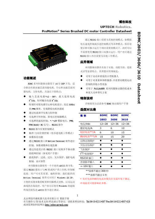
博创科技UPTECH Robotics. ProMotion® Series Brushed DC motor Controller Datasheet功能概述BDMC系列伺服驱动器基于16位DSP开发,适合驱动有刷永磁直流伺服电机,空心杯永磁直流伺服电机,力矩电机。
具备以下的特点:u输入直流电源+12~36V;最大连续电流3~10A,短时输出电流6~15Au特别针对低电感空心杯电机设计,高达80Khz 的PWM频率,有效降低电机热损耗u通过电流调节实现力矩控制u可选择开环控制,即电压控制器模式u可选择的速度控制:+/-10V模拟电压,PWM,PPM(Hobby RC信号),RS232指令u RS232指令位置控制模式u脉冲/方向位置控制(仿步进电机工作模式)u参数保存功能u通过RS232接口和Motion Terminal软件进行控制、参数调整和在线监测u通过改进设计的RS232接口实现多个驱动器的组网控制(参见用户手册)u温度保护,过流、过压、欠压保护,I2T电流限制,高可靠性本伺服驱动器使用一个开放的ASCII指令集,通过RS232通讯口与PC机或用户的上位机/控制板连接,用户可对其设置、编程控制。
我们提供的Motion Terminal软件可应用于Windows 2K/XP:方便的实现参数的配置和伺服模式切换,以及运动曲线的在线监控。
用户亦可以使用Windows的超级终端直接发送ASCII指令进行调试。
通过RS232接口设置为其他控制模式,如模拟电压速度控制或步进控制模式等各种模式,保存设置后即可独立运行于相应设置的模式下。
此时可以不需要使用RS232接口而独立运行。
用户亦可通过RS232接口再次设置为其他工作模式。
应用领域本伺服驱动器具有易于安装、功能全面、连接灵活等显著特点。
其理想应用领域是:u可用于高功率密度的小型机器人u可用于对重量和体积敏感、并需要高精度运动控制的其他小型设备u可用于FAULHABER系列伺服驱动器的低成本和更大功率替代方案特别说明详细使用方法请参考BDMC驱动器用户手册选型对比表指标BDMC2803BDMC3606BDMC3610 电压/Vdc 12~28 12~36 12~36额定电流/A 3 6 10短时电流**/A 6 10 15瞬间电流***/A 10 15 20过热过流保护l l l欠压过压保护l l l飞车保护l l lI2T电流保护l l lRS232接口l l l步进脉冲输入l l l+-10V输入l l l**连续不超过300秒***连续不超过1秒* 短时电流和瞬间电流参数均在室温环境下测定。
- 1、下载文档前请自行甄别文档内容的完整性,平台不提供额外的编辑、内容补充、找答案等附加服务。
- 2、"仅部分预览"的文档,不可在线预览部分如存在完整性等问题,可反馈申请退款(可完整预览的文档不适用该条件!)。
- 3、如文档侵犯您的权益,请联系客服反馈,我们会尽快为您处理(人工客服工作时间:9:00-18:30)。
PAW3606DL-TKDA
PAW3606 Smart Laser Navigator
All rights strictly reserved any portion in this paper shall not be reproduced, copied or transformed to any other forms without permission. 1
PAW3606DL-TKDA Smart Laser Navigator
Figure 1. Top View Pinout Figure 2. Top View of Mouse
PAW3606DL-TKDA Smart Laser Navigator
3. Registers and Operation
4. Specifications
4.3 AC Operating Condition
4.4 DC Electrical Characteristics
PAW3606DL-TKDA Smart Laser Navigator
Package Lid
Lens
OBJECT SURFACE
d e n t
i a l
PAW3606DL-TKDA Smart Laser Navigator
Sensor
PCB
Lens
Base Plate
Figure 6. 3D Assembly for Mounting Instructions
P i x A r t
C o n f i d e n t
i a l
PAW3606DL-TKDA Smart Laser Navigator
PAW3606DL-TKDA Smart Laser Navigator
N N SC SD
PAW3606DL-TKDA Smart Laser Navigator
IDD
PAW3606DL-TKDA Smart Laser Navigator
PAW3606DL-TKDA Smart Laser Navigator
PAW3606DL-TKDA Smart Laser Navigator
Figure 15. Built-in Eye-Safety protection circuit
8.1 LD Eye Safety Protection Circuit Check
The mouse sensor can perform self test for the embedded Eye-Safety protection circuit. To verify this protection ). Monitor MOTSWK/LD_REPORT pin to check the BIST result for approximate SIX frames. High-level MOTSWK/LD_REPORT pin represents the embedded Eye-6 frames, max
t LDBIST Figure 16. LD BIST function Operation A r t
C o f i d e n t
i a
8.2 LD Power Measurement
PixArt Imaging Inc.
PAW3606DL-TKDA Smart Laser Navigator 9. Referencing Application Circuit
9.2 PCB Layout Guideline
Please leave diameter 0.55 mm +0.05 mm on PCB holds to allow IC stick in. Note: No negative tolerance
P i x A r t
C o n f i d e n t
i a l
PAW3606DL-TKDA Smart Laser Navigator 10. Package Information
PAW3606DL-TKDA Smart Laser Navigator
PAW3606DL-TKDA Smart Laser Navigator
P i x A r t
C o n f i d e t
i a l
PAW3606DL-TKDA Smart Laser Navigator
t
C o n f i d e n
PAW3606DL-TKDA Smart Laser Navigator
Base Plate Molding Dimension
All rights strictly reserved any portion in this paper shall not be reproduced, copied or transformed to any other forms without permission . 31P i x A r t
C o n f i d e n t
i a l
PAW3606DL-TKDA Smart Laser Navigator
Sensor PCB
Lens
Base Plate
P i x A r t
C o n f i d e n t
i a l
All rights strictly reserved any portion in this paper shall not be reproduced, copied or transformed to any other forms without permission. 33
PAW3606DL-TKDA Smart Laser Navigator
Note: 1. Dimensions in millimeters.
2. Tolerance is shown on drawing.
P i x A r t
C o n f i d e n t
i a l
PAW3606DL-TKDA Smart Laser Navigator
t
C o n f i d e n
PAW3606DL-TKDA Smart Laser Navigator
Base Plate Molding Dimension
All rights strictly reserved any portion in this paper shall not be reproduced, copied or transformed to any other forms without permission . 36P i x A r t
C o n f i d e n t
i a l
PAW3606DL-TKDA Smart Laser Navigator
PCB
Lens
Base Plate
Sensor
P i x A r t
C o n f i d e n t
i a l。
